Movatterモバイル変換


[0]ホーム

URL:


KR20100029087A - Substrate transport apparatus with multiple movable arms utilizing a mechanical switch mechanism - Google Patents

Substrate transport apparatus with multiple movable arms utilizing a mechanical switch mechanism
Download PDF

Info

Publication number
KR20100029087A
KR20100029087AKR1020097025576AKR20097025576AKR20100029087AKR 20100029087 AKR20100029087 AKR 20100029087AKR 1020097025576 AKR1020097025576 AKR 1020097025576AKR 20097025576 AKR20097025576 AKR 20097025576AKR 20100029087 AKR20100029087 AKR 20100029087A
Authority
KR
South Korea
Prior art keywords
arm
arms
drive
link
independently controllable
Prior art date
Legal status (The legal status is an assumption and is not a legal conclusion. Google has not performed a legal analysis and makes no representation as to the accuracy of the status listed.)
Ceased
Application number
KR1020097025576A
Other languages
Korean (ko)
Inventor
크리스토퍼 호프메이스터
알렉산더 크루피셰브
울리시즈 길크라이스트
마틴 호제크
Original Assignee
브룩스 오토메이션 인코퍼레이티드
Priority date (The priority date is an assumption and is not a legal conclusion. Google has not performed a legal analysis and makes no representation as to the accuracy of the date listed.)
Filing date
Publication date
Application filed by 브룩스 오토메이션 인코퍼레이티드filedCritical브룩스 오토메이션 인코퍼레이티드
Priority claimed from US12/117,415external-prioritypatent/US8752449B2/en
Publication of KR20100029087ApublicationCriticalpatent/KR20100029087A/en
Ceasedlegal-statusCriticalCurrent

Links

Images

Classifications

Landscapes

Abstract

Translated fromKorean

기판 이송 장치는, 프레임; 상기 프레임에 연결되고 적어도 하나의 독립적으로 제어가능한 모터를 포함하는 구동부; 상기 프레임에 연결되고 기판들을 지지하고 이송하기 위해 배치되는 암 링크들을 포함하는 적어도 2 개의 기판 이송 암들; 및 상기 적어도 하나의 독립적으로 제어가능한 모터 및 상기 적어도 2 개의 기판 이송 암들에 결합되고, 상기 적어도 2 개의 기판 이송 암들 중 하나의 펼침 및 접힘을 기동시키면서 상기 적어도 2 개의 기판 이송 암들 중 다른 하나는 실질적으로 접힘 구성으로 남게 하는 기계적 모션 스위치를 포함한다.The substrate transfer apparatus includes a frame; A drive unit coupled to the frame and including at least one independently controllable motor; At least two substrate transfer arms connected to the frame and including arm links arranged to support and transport substrates; And coupled to the at least one independently controllable motor and the at least two substrate transfer arms, the other one of the at least two substrate transfer arms being substantially active while activating the unfolding and folding of one of the at least two substrate transfer arms. And a mechanical motion switch that leaves the folded configuration.

Description

Translated fromKorean
기계적 스위치 메카니즘을 이용한 복수의 가동 암들을 갖는 기판 이송 장치{Substrate transport apparatus with multiple movable arms utilizing a mechanical switch mechanism}Substrate transport apparatus with multiple movable arms utilizing a mechanical switch mechanism}

개시된 실시예들은 기판 이송 장치에 관한 것이며, 더욱 상세하게는, 기계적 스위치 메카니즘을 이용한 복수의 가동 암들을 갖는 기판 이송 장치에 관한 것이다.The disclosed embodiments relate to a substrate transfer apparatus, and more particularly, to a substrate transfer apparatus having a plurality of movable arms using a mechanical switch mechanism.

본 출원은 2007년 5월 8일자로 출원된 미국 임시 특허 출원 제60/916,781호에 기초한 이익을 주장하며, 본 출원은 2007년 5월 8일자로 출원된 미국 임시 특허 출원 제60/916,724호의 관련 출원으로서, 이들의 개시 사항은 참조에 의해 그 전체가 본 명세서에 포함된다.This application claims benefit based on US Provisional Patent Application No. 60 / 916,781, filed May 8, 2007, which relates to US Provisional Patent Application No. 60 / 916,724, filed May 8, 2007. As applications, the disclosures of which are incorporated herein in their entirety by reference.

종래의 다중 암 기판 이송 장치에 있어서, 상기 이송 장치의 암들 또는 링크 부재들(linkages)은 3 개 이상의 모터들의 복잡한 구성에 의해 기동되고, 이들 모터들은, 예를 들면, 상기 이송 장치가 3 이상의 자유도를 갖는 운동이 가능하도록 동축 방식으로 구성되거나 상기 링크 부재들에 동심원으로 배열된 중공 축들(hollow chafts)에 의해 결합된다. 일반적으로, 최외각 축은, 예를 들면, 회전 중심 축 주위로 상기 다중 암들을 회전시키기 위한 허브(hub)에 결합될 수 있다. 예를 들면, 2 개의 내부 축은 독립적인 벨트 및 풀리 구성을 통하여 상기 다중 암들의 각각에 연결될 수 있다. 실제로, 상기 이송 장치의 움직임을 동작시키기 위해 채용되는 모터들의 수가 많을수록 상기 이송 장치의 움직임을 제어하는 제어 시스템의 부담도 더 커진다. 또한, 모터들의 수가 증가할수록 상기 이송 장치의 비용뿐만 아니라 모터의 오동작 가능성도 증가된다.In a conventional multi-arm substrate transfer apparatus, the arms or linkages of the transfer apparatus are activated by a complex configuration of three or more motors, which motors, for example, have three or more degrees of freedom. It is coupled by hollow chafts which are configured in a coaxial manner or arranged concentrically on said link members to enable a movement with a. In general, the outermost axis can be coupled to a hub for rotating the multiple arms, for example around a rotation center axis. For example, two inner axes can be connected to each of the multiple arms via independent belt and pulley configurations. Indeed, the greater the number of motors employed to operate the movement of the transfer device, the greater the burden on the control system controlling the movement of the transfer device. In addition, as the number of motors increases, not only the cost of the transfer device but also the possibility of malfunction of the motor increases.

종래의 다중 암 이송 장치는 이송 챔버들 또는 상기 이송 장치나 구송 시스템이 챔버/설비의 내부에 및/또는 부분적으로 이의 하부에 배치되는 다른 기판 처리 설비에 사용되어, 다른 기판 처리 부품들 (예를 들면, 진공 펌프 등)이 이용할 수 있는 공간은 한계를 갖거나, 어떤 방식으로든 제한된다. 종래의 시스템들에서, 이것은 상기 챔버/설비의 바닥이 아닌 위치에, 예를 들면, 진공 펌프들을 탑재할 수 있는 이송 챔버의 크기를 증가시킬 수 있다. 이에 의해, 비용 상승이 초래된다.Conventional multi-arm transfer devices are used in transfer chambers or other substrate processing facilities in which the transfer device or conveying system is disposed within and / or partially underneath the chamber / equipment, thereby providing other substrate processing components (eg, For example, the space available to a vacuum pump or the like has a limit or is limited in some way. In conventional systems, this can increase the size of the transfer chamber, which can mount, for example, vacuum pumps, in a location other than the bottom of the chamber / equipment. This results in an increase in cost.

종래의 비동축의 나란한 듀얼 스카라 암들(non-coaxial side-by-side dualSelectiveCompliantarticulatedRobotarm arms)은 여러 회사들에 의해 판매용으로 제공되며, 예를 들면, MECS 코리아사(MECS Korea, Inc.)의 UTW 및 UTV 시리즈의 로봇들, 로제 오토메이션사(Rorze automation, Inc.)의 RR 시리즈의 로봇들, 젤사(JEL Corp.)의 LTHR, STHR 및 SPR 시리즈의 로봇들이 있다. 나란한 듀얼 스카라 암 장치의 예는 미국 특허 제5,765,444호에 개시되어 있다.Dual SCARA arms parallel to the conventional non-coaxial (non-coaxial side-by-side dualS electiveC omplianta rticulatedR obota rm arms) are offered for sale by many companies, for example, four MECS Korea ( Robots of the UTW and UTV series of MECS Korea, Inc., robots of the RR series of Rorze automation, Inc., robots of the LTHR, STHR and SPR series of JEL Corp. Examples of side-by-side dual scara arm devices are disclosed in US Pat. No. 5,765,444.

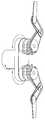
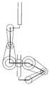
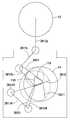
종래의 비동축의 나란한 듀얼 암 로봇의 예시적인 구성은 도 1과 1a에 도시되어 있다. 로봇은 2 개의 스카라 암들 및 링크 부재들을 운반하는 피봇 허브 주 위에 설치된다. 좌측 링크 부재는 외선 조인트들(revolute joints)에 의해 직렬로 결합된 어퍼 암, 포어 암 및 엔드 이펙터를 갖는다. 벨트 및 풀리 구성은 상기 좌측 암의 운동을 제한하여, 상기 허브에 대하여 상기 어퍼 암의 회전이 반대 방향으로 상기 포어 암을 회전시키도록 사용된다(예를 들면, 시계 방향의 어퍼 암의 회전은 반시계 방향의 포어 암의 회전을 기동시킨다). 다른 벨트 및 풀리 구성은 엔드 이펙터의 방사상 배향(radial orientation)을 유지하기 위하여 사용된다. 우측 링크 부재는 상기 좌측 암의 거울 상일 수 있다. 상기 좌측 및 우측 암들의 엔드 이펙터들은 상기 로봇의 2 개의 링크 부재들이 비제한적 움직임을 가능하게 하기 위하여, 서로 다른 수평 평면 내에서 움직인다. 도 1b-1d에 도시된 바와 같이, 상기 좌측 및 우측의 어퍼 암들을 회전시킴으로써, 각각의 링크 부재들은 허브의 피봇지점에 대하여 공통의 방사 방향으로 독립적으로 펼쳐질 수 있다.An exemplary configuration of a conventional non-coaxial side by side dual arm robot is shown in FIGS. 1 and 1A. The robot is installed around a pivot hub that carries two scara arms and link members. The left link member has an upper arm, a fore arm and an end effector coupled in series by revolute joints. A belt and pulley configuration limits the movement of the left arm so that rotation of the upper arm relative to the hub is used to rotate the forearm in the opposite direction (eg, rotation of the upper arm in a clockwise direction is half Activates rotation of the fore arm clockwise). Other belt and pulley configurations are used to maintain the radial orientation of the end effector. The right link member may be a mirror image of the left arm. End effectors of the left and right arms move in different horizontal planes to enable the two link members of the robot to have non-limiting movement. As shown in FIGS. 1B-1D, by rotating the upper and left upper arms, each link member can be independently deployed in a common radial direction with respect to the pivot point of the hub.

도 1, 1a-1d에 도시된 바와 같이, 종래의 나란한(side-by-side) 로봇들에 있어서, 상기 로봇 암들 또는 링크 부재들은 3 개 (이상의) 모터들의 복잡한 구성에 의해 기동되며, 이들 모터들은, 예를 들면, 동축 방식으로 구성될 수 있으며, 상기 로봇에 3의 자유도를 갖는 움직임을 제공하기 위해 이들 모터들은 중공 축들에 의해 상기 로봇에 결합된다. 최외각 축은 상기 허브에 결합될 수 있고, 반면에 2 개의 내부 축들은 독립적인 벨트 및 풀리 구조를 통하여 상기 좌측 및 우측의 링크 부재들의 어퍼 암들에 결합될 수 있다. 이를 구현하는 경우, 상기 로봇 암들의 움직임을 기동시키기 위해 사용되는 모터들의 개수가 많을수록, 로봇의 움직임을 제어하는 제어 시스템에 인가되는 부담은 더욱 커진다. 또한, 사용되는 모터들의 개 수가 많을수록, 상기 로봇의 비용뿐만 아니라 모터의 오동작 가능성도 증가한다.As shown in Figs. 1, 1A-1D, in conventional side-by-side robots, the robot arms or link members are activated by a complex configuration of three (or more) motors, They can be configured, for example, in a coaxial manner, and these motors are coupled to the robot by hollow axes to provide the robot with three degrees of freedom. The outermost axis can be coupled to the hub, while the two inner axes can be coupled to the upper arms of the left and right link members via independent belt and pulley structures. In the implementation of this, the greater the number of motors used to activate the movement of the robot arms, the greater the burden applied to the control system for controlling the movement of the robot. Also, the greater the number of motors used, the higher the cost of the robot as well as the likelihood of malfunction of the motor.

분위기 조절 시스템과 같은 챔버 내에 부설되는 다른 부품들 (예를 들면, 이송 챔버의 바닥에 부설되는 진공 펌프들)을 탑재하기 위해 이용되는 공간 인벨로프(space envelope)를 실질적으로 금지하거나 기껏해야 방해하거나 제한하도록 상기 로봇과 구동부가 챔버 내에 배치되는 이송 챔버들 내에, 도 1a-도 1d에 도시된 바와 같은 종래의 나란한 로봇들이 이용된다. 종래의 시스템들에서, 이것은 챔버의 바닥이 아닌 다른 위치에 진공 펌프들을 탑재하기 위한 이송 챔버의 크기를 증가시킬 수 있다. 이에 의해 비용 상승이 초래된다.Substantially prohibit or at most interfere with the space envelope used to mount other components installed in the chamber, such as an atmosphere control system (eg, vacuum pumps installed at the bottom of the transfer chamber). Conventional side-by-side robots, such as those shown in FIGS. 1A-1D, are used in transfer chambers in which the robot and the drive are disposed in the chamber to restrict or limit them. In conventional systems, this may increase the size of the transfer chamber for mounting the vacuum pumps at a location other than the bottom of the chamber. This results in an increase in cost.

따라서, 복잡도 및 저장 면적이 감소되고, 신뢰성 및 청결도가 향상된 로봇 시스템을 갖는 독립적으로 움직일 수 있는 암들을 갖는 로봇 매니퓰레이터를 제공하는 것은 바람직하다.Accordingly, it is desirable to provide a robot manipulator with independently movable arms having a robot system with reduced complexity and storage area and improved reliability and cleanliness.

일 실시예에서, 기판 이송 장치가 제공된다. 상기 기판 이송 장치는, 프레임, 상기 프레임에 연결되고 적어도 하나의 독립적으로 제어가능한 모터를 포함하는 구동부, 상기 프레임에 연결되고 기판들을 지지하고 이송하기 위하여 배치된 암 링크들을 포함하는 적어도 2 개의 기판 이송 암들 및 상기 적어도 독립적으로 제어가능한 모터 및 상기 적어도 2 개의 기판 이송 암들에 결합되는 기계적 모션 스위치를 포함하며, 상기 기계적 모션 스위치는 상기 적어도 하나의 독립적으로 제어가능한 모터들에 의하여 제 1 축 주위로 회전가능하게 구동되는 피봇 부재와 제 1 및 제 2 연결 링크들을 포함하며, 각각의 연결 링크들은 일 단부에서 상기 피봇 부재에 회전가능하게 결합되고, 제 2 반대쪽 단부에서 각각의 구동 링크에 회전가능하게 결합되며, 상기 구동 링크들은 서로에 대하여 나란히 배치되고 상기 제 1 축과 이격된 제 2 및 제 3 축 주위로 상기 프레임에 회전가능하게 결합되고, 각각의 구동 링크는 상기 적어도 2 개의 기판 이송 암들 중 어느 하나의 펼침 및 접힘을 기동시키면서 상기 적어도 2 개의 기판 이송 암들 중 다른 하나는 실질적으로 접힘 구성으로 남아 있게 하기 위하여 상기 적어도 2 개의 기판 이송 암들의 상기 암 링크들 중 각각의 어퍼 암 링크에 구동가능하게 결합된다.In one embodiment, a substrate transfer device is provided. The substrate transfer device includes at least two substrate transfers including a frame, a drive portion coupled to the frame and at least one independently controllable motor, and arm links connected to the frame and arranged to support and transfer the substrates. A mechanical motion switch coupled to arms and said at least independently controllable motor and said at least two substrate transfer arms, said mechanical motion switch being rotated about a first axis by said at least one independently controllable motor. A pivotally driven pivot member and first and second connection links, each connection links rotatably coupled to the pivot member at one end and rotatably coupled to each drive link at a second opposite end. The drive links are arranged side by side with respect to each other Rotatably coupled to the frame about second and third axes spaced from the first axis, each drive link activating the unfolding and folding of any of the at least two substrate transfer arms; Another one of the transfer arms is operatively coupled to each upper arm link of the arm links of the at least two substrate transfer arms to remain in a substantially folded configuration.

다른 실시예에서, 기판 이송 장치가 제공된다. 상기 기판 이송 장치는 구동부 및 상기 구동부에 동작가능하게 연결되어 이동되는 스카라 암을 포함하며, 상기 스카라 암은 어퍼 암 및 상기 어퍼 암 상에 동작가능하게 탑재되고 상부에 기판을 파지(holding)할 수 있는 적어도 2 개의 포어 암들을 포함하며, 상기 어퍼 암은 실질적으로 강체 링크이고, 상기 어퍼 암 내부에 배치되고 상기 구동부에 동작가능하게 연결되는 기계적 모션 스위치는 상기 구동부의 단지 하나의 모터에 의해 가동되고 상기 적어도 2 개의 포어 암들 중 다른 하나와 실질적으로 독립적인 상기 적어도 2 개의 포어 암들 중 하나의 회전을 선택적으로 기동시키도록 구성된다.In another embodiment, a substrate transfer device is provided. The substrate transfer device includes a drive unit and a scara arm operatively connected to and moved by the drive unit, wherein the scara arm is operably mounted on the upper arm and the upper arm and can hold a substrate thereon. At least two fore arms, wherein the upper arm is substantially a rigid link, and a mechanical motion switch disposed within the upper arm and operably connected to the drive is driven by only one motor of the drive and And selectively activate rotation of one of the at least two pore arms that is substantially independent of the other of the at least two pore arms.

또 다른 실시예에서, 기판 이송 장치가 제공된다. 상기 기판 이송 장치는 프레임, 상기 프레임에 연결되고 적어도 하나의 독립적으로 제어가능한 모터를 포함하는 구동부, 상기 프레임에 연결되고 기판들을 지지하고 이송하기 위해 배치된 암 링크들을 포함하는 적어도 2 개의 기판 이송 암들, 및 상기 적어도 하나의 독립적으로 제어가능한 모터 및 상기 적어도 2 개의 기판 이송 암들에 결합되는 컴팩트 기계적 모션 스위치를 포함하며, 상기 기계적 모션 스위치는 상기 적어도 하나의 독립적으로 제어가능한 모터에 의해 제 1 축 주위로 회전가능하게 구도되는 피봇 부재, 및 상기 적어도 2 개의 기판 이송 암들의 상기 암 링크들과 구별되는 제 1 및 제 2 구동 링크들을 포함하며, 각각의 구동 링크는 일 단부에서 각각의 제 1 조인트에서 상기 피봇 부재에 회전가능하게 결합되고 반대쪽의 제 2 단부에서는 각각의 제 2 조인트에서 상기 적어도 2 개의 기판 이송 암들 중 각각의 어퍼 암 링크에 회전가능하게 결합되며, 상기 제 1 구동 링크는 상기 제 2 구동 링크 상으로 교차하고, 상기 제 1 축과 상기 각각의 제 1 조인트들 사이의 거리는 상기 각각의 제 1 조인트로부터 상기 각각의 제 2 조인트까지의 거리와 실질적으로 동일하다.In yet another embodiment, a substrate transfer device is provided. The substrate transfer device comprises at least two substrate transfer arms including a frame, a drive portion coupled to the frame and at least one independently controllable motor, and arm links connected to the frame and arranged to support and transport the substrates. And a compact mechanical motion switch coupled to the at least one independently controllable motor and the at least two substrate transfer arms, the mechanical motion switch being moved about a first axis by the at least one independently controllable motor. And a first and second drive links that are distinct from the arm links of the at least two substrate transfer arms, each drive link being at each end at each first joint. Is rotatably coupled to the pivot member and at an opposite second end Rotatably coupled to each upper arm link of the at least two substrate transfer arms at each second joint, the first drive link intersect on the second drive link, the first axis and the respective The distance between the first joints is substantially equal to the distance from each of the first joints to each of the second joints.

개시된 실시예들에 관한 전술한 특징들 및 다른 특징들은 첨부된 아래의 도면과 관련하여 하기의 개시사항으로부터 설명된다.The foregoing and other features of the disclosed embodiments are set forth in the following disclosure in conjunction with the accompanying drawings below.

도 1 및 1a-1d는 복수의 가동 암들을 갖는 종래의 기판 이송 장치를 도시한다.1 and 1A-1D show a conventional substrate transfer apparatus having a plurality of movable arms.

도 2a-2d는 본 명세서에 개시된 일 실시예에 따른 특징을 갖는 예시적인 처리 장치를 도시한다.2A-2D illustrate example processing apparatus having features in accordance with one embodiment disclosed herein.

도 3a-3b는 도 2의 처리 장치의 이송 장치의 구동부에 관하여, 예시적인 실시예들에 따른 이송 장치의 다른 위치들을 개략적으로 도시한다.3A-3B schematically show different positions of the conveying apparatus according to exemplary embodiments with respect to the drive of the conveying apparatus of the processing apparatus of FIG. 2.

도 4a-4c는 이송 챔버 모듈 및 도 3a-3b에 도시된 구동부를 갖는 기판 이송 장치를 개략적으로 도시하며, 도 4d는 상기 이송 챔버 및 이송 장치를 도시하는 부분 입면도이다.4A-4C schematically show a substrate transfer device having a transfer chamber module and a drive shown in FIGS. 3A-3B, and FIG. 4D is a partial elevation view of the transfer chamber and transfer device.

도 4e는 일 실시예에 따른 구동부의 일부를 개략적으로 도시하는 단면도이다.4E is a schematic cross-sectional view of a portion of a driving unit according to an embodiment.

도 5a-5d는 각각 4 개의 다른 펼침 위치에 있는 도 4a-4c의 기판 이송 장치를 개략적으로 도시한다.5A-5D schematically illustrate the substrate transfer device of FIGS. 4A-4C in four different unfolded positions, respectively.

도 6a-6c는 각각 다른 3 개의 펼침 위치에 있는 기판 이송 장치를 개략적으로 도시한다.6A-6C schematically illustrate the substrate transfer apparatus in three different unfolded positions.

도 7a-7e는 각각 또 다른 회전 위치에 있는 기판 이송 장치를 개략적으로 도시한다.7A-7E schematically illustrate substrate transport apparatuses, each in another rotational position.

도 8a-8c는 각각 기판 이송 장치의 3 개의 대응하는 펼침/접힘 위치에 있는 각 암의 부분들을 도시한다.8A-8C show portions of each arm in three corresponding unfolded / folded positions of the substrate transfer device, respectively.

도 9a-9d는 다른 위치에 있는 기판 이송 장치의 암 위치들을 개략적으로 도시한다.9A-9D schematically show the arm positions of the substrate transfer device in different positions.

도 10a-10b는 다른 실시예에 따른 기판 이송 장치를 개략적으로 도시한다.10A-10B schematically illustrate a substrate transfer apparatus according to another embodiment.

도 11a-11d는 4 개의 다른 펼침 위치에 있는 기판 이송 장치의 2 개의 암들을 갖는 도 10a-10b에 도시된 기판 이송 장치를 개략적으로 도시한다.11A-11D schematically illustrate the substrate transfer device shown in FIGS. 10A-10B with two arms of the substrate transfer device in four different extended positions.

도 12a-12b는 다른 실시예에 따른 이송 장치의 다른 부분의 개략도와 상기 이송 장치의 움직임을 도시하는 그래프이다.12A-12B are graphs showing a schematic diagram of another part of a conveying apparatus according to another embodiment and the movement of the conveying apparatus.

도 13a-13c는 이송 챔버 모듈 및 도 12a-12b의 기판 이송 장치를 개략적으로 도시한다.13A-13C schematically illustrate the transfer chamber module and the substrate transfer device of FIGS. 12A-12B.

도 14a-14c는 각각 다른 실시예에 따라 3 개의 다른 펼침 위치에 있는 기판 이송 장치를 개략적으로 도시한다.14A-14C schematically illustrate substrate transfer devices in three different unfolded positions, respectively, according to another embodiment.

도 15a-15c는 각각 또 다른 실시예에 따라 다른 3 개의 펼침 위치에 있는 기판 이송 장치를 개략적으로 도시한다.15A-15C schematically illustrate substrate transfer devices in three different unfolded positions, respectively, according to another embodiment.

도 16a-16d는 각각 또 다른 실시예에 따라 4 개의 다른 위치에 있는 기판 이송 장치를 개략적으로 도시한다.16A-16D schematically illustrate substrate transfer devices in four different positions, each according to yet another embodiment.

도 17a-17c는 또 다른 이송 챔버 모듈 및 기판 이송 장치를 개략적으로 도시한다.17A-17C schematically illustrate another transfer chamber module and substrate transfer device.

도 18a-18d는 다른 실시예에 따라 이송 챔버 모듈과 2 개의 암들 중 하나의 암이 4 개의 다른 펼침 위치에 있는 기판 이송 장치를 개략적으로 도시한다.18A-18D schematically illustrate a substrate transfer device with a transfer chamber module and one of the two arms in four different unfolded positions according to another embodiment.

도 19a-19c는 2 개의 암들 중 하나의 암이 3 개의 다른 펼침 위치에 있는 또 다른 실시예에 따른 듀얼 정방형(bisymmetric) 스카라암을 갖는 기판 이송 장치를 개략적으로 도시한다.19A-19C schematically show a substrate transfer apparatus with dual bisymmetric scaraarms according to another embodiment in which one of the two arms is in three different unfolded positions.

도 20a-20l은 이송 챔버 모듈 및 2 개의 암들 각각이 5 개의 다른 펼침 위치에 있는 기판 이송 장치를 개략적으로 도시한다.20A-20L schematically illustrate a substrate transfer device in which the transfer chamber module and each of the two arms are in five different unfolded positions.

도 21a는 종래의 이송 장치를 도시한다.21A shows a conventional transfer device.

도 21b는 다른 실시예에 따른 이송 챔버 모듈 및 기판 이송 장치를 개략적으로 도시한다.21B schematically illustrates a transfer chamber module and a substrate transfer device according to another embodiment.

도 22a-22b는 8 개의 다른 회전 위치에 있는 도 20a-20b의 기판 이송 장치를 개략적으로 도시한다.22A-22B schematically illustrate the substrate transfer device of FIGS. 20A-20B in eight different rotational positions.

도 23a-23b는 링크 부재에 의해 구동되며 독립적으로 기동되는 동축 링들을 갖는 단일 엔드 이펙터 암의 역학도(kinetic diagram) 및 단계적 움직임의 방사상의 펼침도(phased motion radial extension diagram)이다.23A-23B are kinetic diagrams of single-end effector arms with coaxial rings driven independently by a link member and phased motion radial extension diagrams of stepped movements.

도 24a-24b는 곧은 밴드들(bands)에 의해 구동되는 독립적으로 기동되는 동축 링들을 갖는 단일 엔드 이펙터 암의 역학도 및 단계적 움직임의 방사상의 펼침도이다.24A-24B are dynamic views of the single end effector arm with independently actuated coaxial rings driven by straight bands and radial unfolded views of stepwise movement.

도 25a-25b는 교차된 밴드들에 의해 구동되는 독립적으로 기동되는 동축 링들을 갖는 단일 엔드 이펙터 암의 역학도 및 단계적 움직임의 방사상의 펼침도이다.25A-25B are dynamic unfolded and radial unfolded diagrams of stepwise movement of a single end effector arm with independently actuated coaxial rings driven by crossed bands.

도 26a-26b는 자성 커플링 부재에 의해 구동되는 독립적으로 기동되는 동축 링들을 갖는 단일 엔드 이펙터 암의 역학도 및 단계적 움직임의 방사상의 펼침도이다.26A-26B are dynamic views of the single end effector arm with independently actuated coaxial rings driven by a magnetic coupling member and radial unfolded views of stepwise movement.

도 27a-27b는 링크 부재들에 의해 구동되는 독립적으로 기동되는 동축 링들을 갖는 이중 엔드 이펙터 암의 역학도 및 단계적 움직임의 방사상의 펼침도이다.27A-27B are dynamic views of the dual end effector arm with independently actuated coaxial rings driven by the link members and radial unfolded views of the stepwise movement.

도 28a-28b는 다른 기하학적 구성을 갖는 링크 부재에 의해 구동되는 독립적으로 기동되는 동축 링들을 갖는 이중 엔드 이펙터 암의 역학도 및 단계적 움직임의 방사상의 펼침도이다.28A-28B are dynamic views and radial unfolds of stepped motion of a dual end effector arm with independently actuated coaxial rings driven by link members having different geometries.

도 29a-29g는 다른 구성을 갖는 실시예에 따른 기판 이송 장치를 도시한다.29A-29G show a substrate transfer apparatus according to an embodiment having another configuration.

도 30a 및 30b는 일 실시예에 따른 이송 장치를 개략적으로 도시한다.30A and 30B schematically show a transport device according to one embodiment.

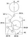
도 31a-31c는 일 실시예에 따른 이송 장치의 커플링 시스템을 개략적으로 도시한다.31A-31C schematically show a coupling system of a conveying device according to one embodiment.

도 32a-32d, 33a-33d, 34a, 34d, 35a-35d 및 36a-36d는 일 실시예에 따른 이송 장치를 개략적으로 도시한다.32A-32D, 33A-33D, 34A, 34D, 35A-35D and 36A-36D schematically illustrate a transfer device according to one embodiment.

도 37은 일 실시예에 따른 기계적 모션 스위치의 동작을 도시한다.37 illustrates operation of a mechanical motion switch according to one embodiment.

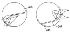
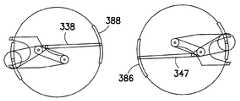
도 38a-38e는 일 실시예에 따른 이송 장치의 예시적 동작을 개략적으로 도시한다.38A-38E schematically illustrate an exemplary operation of a transport apparatus according to one embodiment.

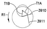
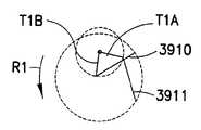
도 39는 다른 실시예에 따른 이송 장치의 일부를 개략적으로 도시한다.39 schematically shows a part of a conveying apparatus according to another embodiment.

도 40a-40c는 일 실시예에 따른 기계적 모션 스위치를 도시한다.40A-40C illustrate a mechanical motion switch according to one embodiment.

도 41은 일 실시예에 따른 이송 장치의 예시적 동작 프로파일을 도시한다.41 shows an exemplary operating profile of the transport apparatus according to one embodiment.

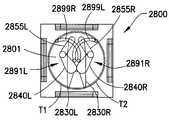
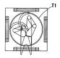
도 42a-42d, 43 및 44는 일 실시예에 따른 이송 장치의 예시적 동작을 개략적으로 도시한다.42A-42D, 43 and 44 schematically illustrate exemplary operation of a transport apparatus according to one embodiment.

도 45a-45c는 일 실시예에 따른 기계적 모션 스위치를 개략적으로 도시한다.45A-45C schematically illustrate a mechanical motion switch according to one embodiment.

도 46a-46d는 일 실시예에 따른 이송 장치의 예시적 동작을 개략적으로 도시한다.46A-46D schematically illustrate an example operation of a transfer device according to one embodiment.

개시된 실시예가 도면들에 도시된 실시예를 참조하여 설명되지만, 개시된 실시예들은 다양한 선택적인 실시예들로 구현될 수 있음을 이해하여야 한다. 또한, 임의의 적합한 크기, 형상 또는 종류의 구성 부재들 또는 재료들이 이용될 수 있다.Although the disclosed embodiment is described with reference to the embodiment shown in the drawings, it should be understood that the disclosed embodiments may be implemented in various alternative embodiments. In addition, any suitable size, shape or type of constituent members or materials may be used.

독립적인 가동 암들을 갖는 매니퓰레이터를 구비하는 기판 이송 장치가 제공되며, 2 개의 독립적으로 제어가능한 모터들만을 가지고서도 상기 독립적인 가동 암들은 기계적 스위치 메카니즘을 이용하여 상기 2 이상의 암들이 결합된 회전 및 독립적인 집기(pick)/놓기(place) 동작을 가질 수 있도록 한다(예를 들면, 각 암들의 적어도 하나의 자유도가 다른 암들의 자유도와 실질적으로 독립적이면서도, 각 암들은 2 이상의 자유도를 갖는다). 2 이상의 암들에 대한 구동은 예를 들면 진공 이송 챔버 벽들 내부로 일체화되어, 진공 시스템 부품들(진공 펌프들, 게이지들 및 밸브들)을 챔버의 저부에 일체화시킨다. 일 실시예에서, 상기 암들의 쇼울더부들은 중심에서 어긋나게 (처리 스테이션에 더 가까이) 배치되며, 그 결과 SEMI(Semiconductor Equipment and Materials International)를 갖는 분절 암들이 로봇에 도달하게 되면서도 종래의 암들보다 더 작을 수 있다.A substrate transfer apparatus having a manipulator having independent movable arms is provided, and even with only two independently controllable motors, the independent movable arms utilize a mechanical switch mechanism to rotate and independently combine the two or more arms. Enable to have a pick / place operation (eg, each arm has two or more degrees of freedom while at least one degree of freedom of each arm is substantially independent of the degrees of freedom of the other arms). The drive to the two or more arms is for example integrated into the vacuum transfer chamber walls to integrate the vacuum system components (vacuum pumps, gauges and valves) at the bottom of the chamber. In one embodiment, shoulder portions of the arms are disposed off-centered (closer to the processing station), so that segment arms with SEMI (Semiconductor Equipment and Materials International) reach the robot while being smaller than conventional arms. Can be.

도 2a-2d는 본 명세서에 개시된 실시예에 따른 특징들을 포함하는 기판 처리 장치 또는 툴들의 개략도이다.2A-2D are schematic diagrams of substrate processing apparatus or tools incorporating features in accordance with an embodiment disclosed herein.

도 2a 및 2b를 참조하면, 본 명세서에서 더욱 상세히 개시된 바와 같이, 실시예들의 특징들을 포함하는 기판 처리 장치 또는 툴들이 개략적으로 도시된다. 도면들에서는 반도체 툴들이 도시되어 있지만, 본 명세서에 개시되는 실시예들은 로봇 매니퓰레이터들을 사용하는 임의의 툴 스테이션 또는 응용 장치에 적용될 수 있다. 이러한 실시예에서, 툴(1090)은 클러스터 툴(cluster tool)로 나타내었지 만, 예시적인 실시예들은 예를 들면, 도 2c 및 2d에 도시되어 있고, 본 명세서에 참조에 의해 개시 사항 전체가 포함된 "Linearly Distributed Semiconductor Workpiece Processing Tool(선형적으로 안배된 반도체 피처리체 처리 툴)"이란 제하의 미국 특허 출원 제11/442, 511호에 개시된 선형 툴(linear tool)과 같은 임의의 적합한 툴 스테이션에 적용될 수도 있다. 툴 스테이션(1090)은 일반적으로 대기 프론트 엔드(atmospheric front end; 100), 진공 로드 락(1010) 및 진공 백 엔드(1020)을 포함한다. 다른 실시예들에서, 상기 툴 스테이션은 임의의 적합한 구성을 가질 수도 있다. 프론트 엔드(1000), 로드 락(1010) 및 백 엔드(1020)의 각 부품들은 예를 들면 클러스터형 아키텍쳐 제어부와 같은 임의의 적합한 제어 아키텍쳐의 일부분일 수 있다. 상기 제어 시스템은 본 명세서에 참조에 의해 개시 사항 전체가 포함된 "Scalable Motion Control System(측정가능한 동작 제어 시스템)"이란 제하의, 2005년 7월 11일자로 출원된 미국 특허 출원 제11/18, 615호에 개시된 것들과 같은 마스터 제어부, 클러스터 제어부들 및 자율적(autonomous) 원격 제어부들을 갖는 폐쇄형 루프 제어부일 수 있다. 다른 실시예들에서, 임의의 적합한 제어부 및/또는 제어 시스템이 이용될 수도 있다.2A and 2B, substrate processing apparatus or tools including the features of the embodiments are schematically illustrated as disclosed in more detail herein. Although semiconductor tools are shown in the figures, the embodiments disclosed herein may be applied to any tool station or application using robotic manipulators. In this embodiment, thetool 1090 is shown as a cluster tool, but exemplary embodiments are shown, for example, in FIGS. 2C and 2D, which are incorporated by reference herein in their entirety. "Linearly Distributed Semiconductor Workpiece Processing Tool" refers to any suitable tool station, such as the linear tool disclosed in US patent application Ser. No. 11 / 442,511, issued below. May be applied.Tool station 1090 generally includes an atmosphericfront end 100, avacuum load lock 1010 and a vacuumback end 1020. In other embodiments, the tool station may have any suitable configuration. Each component of thefront end 1000,load lock 1010 andback end 1020 may be part of any suitable control architecture, such as, for example, a clustered architecture control. The control system is described in US patent application Ser. No. 11/18, filed Jul. 11, 2005, entitled "Scalable Motion Control System", which is hereby incorporated by reference in its entirety. It may be a closed loop control with master controls, cluster controls, and autonomous remote controls, such as those disclosed in 615. In other embodiments, any suitable control and / or control system may be used.

본 실시예들에 있어서, 프론트 엔드(1000)는 일반적으로 로드 포트 모듈들(1005), 및 예를 들면 설비 프로트 엔드 모듈(equipment front end module; EFEM)과 같은 미니 환경(mini-environment; 1060)을 포함한다. 로드 포트 모듈들(1005)은 300 mm 로드 포트들, 전방 개방 또는 바닥 개방형(front opening or bottom opening) 박스들/포드들 및 카세트들에 대한 SEMI 표준 E15.1, E47.1, E62, E19.5 또는 E1.9을 따르는 BOLTS(box/opener/loader to tool standards) 인터페이스들일 수 있다. 다른 실시예들에서, 상기 로드 포트 모듈은, 예를 들면, 200 mm 웨이퍼 인터페이스들로서, 또는, 예를 들면, 크거나 더 작은 웨이퍼들 또는 평판 디스플레이를 위한 평판 패널과 같은 임의의 다른 적합한 기판 인터페이스들로서 구성될 수도 있다. 도 2a에는 2 개의 로드 포트 모듈들이 도시되어 있으나, 다른 실시예들에서는, 프로트 엔드(1000) 내부로 임의의 적합한 개수의 로드 포트 모듈들이 삽입될 수도 있다. 로드 포트 모듈들(1005)은 오버헤드 이송 시스템(overhead transport system), 자동 안내형 이송 수단들(automatic guided vehicle), 유인 이송 수단들(person guided vehicle), 레일 안내형 이송 수단들(rail guided vehicles)로부터 또는 임의의 다른 적합한 이송 방법으로부터 기판 캐리어들 또는 카세트들(1050)을 수용하도록 구성될 수 있다. 로드 포트 모듈들(1005)은 로드 포트들(1040)을 통하여 미니 환경(1060)과 접할 수 있다. 로드 포트들(1040)은 기판 카세트들(1050)과 미니 환경(1060) 사이의 기판들의 통로를 확보할 수 있도록 한다. 미니 환경(1060)은 하기의 이송 로봇(1013)을 포함한다. 일 실시예에서, 로봇(1030)은 예를 들면, 본 명세서에 그 전체가 참조에 의해 포함된 미국 특허 제6,002,840호에 개시된 것과 같은 트랙 마운트형 로봇일 수 있다. 미니 환경(1060)은 복수의 로드 포트 모듈들 사이에서 기판 이송을 위한 제어되고 청결한 영역을 제공할 수 있다.In the present embodiments, thefront end 1000 is generally a mini-environment 1060 such asload port modules 1005 and, for example, an equipment front end module (EFEM). It includes.Load port modules 1005 are SEMI standards E15.1, E47.1, E62, E19 for 300 mm load ports, front opening or bottom opening boxes / pods and cassettes. It may be box / opener / loader to tool standards (BOLTS) interfaces conforming to 5 or E1.9. In other embodiments, the load port module is, for example, as 200 mm wafer interfaces, or as any other suitable substrate interfaces such as, for example, large or smaller wafers or a flat panel for flat panel display. It may be configured. Although two load port modules are shown in FIG. 2A, in other embodiments, any suitable number of load port modules may be inserted into thefront end 1000. Theload port modules 1005 may include an overhead transport system, automatic guided vehicles, person guided vehicles, rail guided vehicles. ), Or from any other suitable transfer method, may be configured to receive substrate carriers orcassettes 1050. Theload port modules 1005 may be in contact with themini environment 1060 through theload ports 1040.Load ports 1040 allow for passage of substrates betweensubstrate cassettes 1050 andmini environment 1060. The mini-environment 1060 includes the followingtransfer robot 1013. In one embodiment, therobot 1030 may be, for example, a track mounted robot such as disclosed in US Pat. No. 6,002,840, which is incorporated by reference in its entirety herein. Themini environment 1060 may provide a controlled and clean area for substrate transfer between a plurality of load port modules.

진공 로드 락(1010)은 미니-환경(1060)과 백 엔드(1020) 사이에 위치될 수도 있고 연결될 수도 있다. 일반적으로, 로드 락(1010)은 대기 및 진공 슬롯 밸브들 을 포함한다. 이 슬롯 밸브들은 대기 프런트 엔드로부터 기판을 로딩한 이후에 로드 락을 배기하고, 질소와 같은 불활성 가스로 락을 배출할 때 이송 챔버에서 진공을 유지하기 위해 이용된 환경적 분리를 제공할 수도 있다. 로드 락(1010) 은 또한, 프로세싱하는 소정의 위치에 기판의 기준을 정렬하는 정렬기(1011)를 포함할 수도 있다. 다른 실시예들에서, 진공 로드 락은 프로세싱 장치의 임의의 적합한 위치에 위치될 수도 있으며, 임의의 적합한 구성을 가질 수도 있다.Thevacuum load lock 1010 may be located and connected between the mini-environment 1060 and theback end 1020. In general, theload lock 1010 includes atmospheric and vacuum slot valves. These slot valves may provide an environmental separation used to evacuate the load lock after loading the substrate from the atmospheric front end and to maintain a vacuum in the transfer chamber when discharging the lock with an inert gas such as nitrogen. Theload lock 1010 may also include analigner 1011 that aligns the reference of the substrate at a predetermined location for processing. In other embodiments, the vacuum load lock may be located at any suitable location of the processing apparatus and may have any suitable configuration.

일반적으로, 진공 백 엔드(1020)는 이송 챔버(1025), 하나 이상의 프로세싱 스테이션(들)(1030) 및 이송 로봇(1014)을 포함한다. 이송 로봇(1014)이 이하 설명될 것이며, 로드 락(1010)과 다양한 프로세싱 스테이션들(1030) 사이에서 기판들을 이송하기 위해 이송 챔버(1025) 내에 위치될 수도 있다. 프로세싱 스테이션들(1030)은 기판들상에 전기 회로 또는 다른 소망의 구조를 형성하기 위해 다양한 증착, 에칭, 또는 다른 타입의 프로세스들을 통해 기판들에 대해 동작할 수도 있다. 통상의 프로세스들은, 플라즈마 에칭 또는 다른 에칭 프로세스, 화학적 기상 증착(CVD), 플라즈마 기상 증착(PVD), 이온 주입과 같은 주입 공정, 측정(metrology), 급속 열처리 (RTP), 건식 스트립, 원자층 증착(ALD), 산화/확산, 질화물 형성 공정, 진공 리소그래피, 에피택시, 와이어 본딩 및 증발법(evaporation)과 같은 박막 프로세스들, 또는 진공 입력을 사용하는 다른 박막 프로세스들을 포함하지만, 이에 제한되지 않는다. 프로세싱 스테이션들(1030)은 기판들이 이송 챔버(1025)로부터 프로세싱 스테이션들(1030)로 그리고 그 역으로 전달되는 것이 가능하도록 이송 챔버(1025)에 연결된다.Generally, the vacuumback end 1020 includes atransfer chamber 1025, one or more processing station (s) 1030, and atransfer robot 1014. Atransfer robot 1014 will be described below and may be located within thetransfer chamber 1025 to transfer substrates between theload lock 1010 and thevarious processing stations 1030.Processing stations 1030 may operate on the substrates through various deposition, etching, or other types of processes to form an electrical circuit or other desired structure on the substrates. Conventional processes include plasma etching or other etching processes, chemical vapor deposition (CVD), plasma vapor deposition (PVD), implantation processes such as ion implantation, metrology, rapid heat treatment (RTP), dry strips, atomic layer deposition Thin film processes such as (ALD), oxidation / diffusion, nitride formation process, vacuum lithography, epitaxy, wire bonding and evaporation, or other thin film processes using vacuum input.Processing stations 1030 are connected to thetransfer chamber 1025 to enable substrates to be transferred from thetransfer chamber 1025 to theprocessing stations 1030 and vice versa.

이제, 도 2c를 참조하면, 선형 기판 프로세싱 시스템(2010)의 개략적인 평면도가 도시되며, 여기서, 툴 인터페이스부(2012)가 이송 챔버 모듈(3018)에 탑재되어, 인터페이스부(2012)는 일반적으로 이송 챔버(3018)의 세로 X 축을 향해 (예를 들어, 내부로) 대면하지만, 그로부터 오프셋된다. 이송 챔버 모듈(3018)은 참조에 의해 본 명세서에 포함된 미국 특허 출원 제11/442,511호에 기재된 바와 같이 인터페이스들(2050,2060,2070)에 다른 이송 챔버 모듈들(3018I,3018J)을 부착함으로써 임의의 적절한 방향으로 펼쳐질 수도 있다. 각 이송 챔버 모듈(3018, 3019A, 3018I, 3018J)은 예를 들어, 프로세싱 시스템(2010) 전반적으로 및 프로세싱 모듈(PM) 내부로 및 외부로 기판을 이송하는 이하 매우 상세히 설명하는 바와 같은 기판 이송부(2080)를 포함한다. 인식될 수도 있는 바와 같이, 각 챔버 모듈은 분리되거나 제어된 대기(예를 들어, N2, 클린 에어, 진공)를 홀딩할 수도 있다.Referring now to FIG. 2C, a schematic plan view of a linearsubstrate processing system 2010 is shown, where atool interface portion 2012 is mounted to atransfer chamber module 3018 so that theinterface portion 2012 is generally Facing toward (eg, inwardly) the longitudinal X axis of thetransfer chamber 3018 but offset therefrom. Thetransfer chamber module 3018 is attached by attaching othertransfer chamber modules 3018I, 3018J to theinterfaces 2050, 2060, 2070 as described in US patent application Ser. No. 11 / 442,511, incorporated herein by reference. It may be unfolded in any suitable direction. Eachtransfer chamber module 3018, 3019A, 3018I, 3018J is, for example, a substrate transfer unit as described in greater detail below, which transfers the substrate throughout theprocessing system 2010 and into and out of the processing module PM ( 2080). As may be appreciated, each chamber module may hold a separate or controlled atmosphere (eg,N 2, clean air, vacuum).

도 2d를 참조하면, 선형 이송 챔버(416)의 세로 축을 따라 취해진 바와 같은 예시적인 프로세싱 툴(410)의 입면도가 도시되어 있다. 도 2d에 도시된 예시적인 실시예에서, 인터페이스부(12)는 대표적으로 이송 챔버(416)에 연결될 수도 있다. 이러한 예시적인 실시예에서, 이송 챔버(12)는 툴 이송 챔버(416)의 하나의 엔드를 정의할 수도 있다. 도 2d에서 알 수 있는 바와 같이, 이송 챔버(416)는 예를 들어, 인터페이스부(12)로부터 대향하는 엔드에서 다른 피처리체 입/출구 스테이션(413)을 가질 수도 있다. 다른 실시예들에서, 이송 챔버로부터 피처리체들을 삽입/제거하는 다른 입/출구 스테이션들이 제공될 수도 있다. 예시적인 실시예에서, 인터페이스부(12) 및 입/출구 스테이션(412)은 툴로부터의 피처리체들의 로딩 및 언로딩을 허용할 수도 있다. 다른 실시예들에서, 피처리체들은 일 엔드로부터 툴로 로딩될 수도 있고 다른 엔드로부터 제거될 수도 있다. 예시적인 실시예에서, 이송 챔버(416)는 하나 이상의 이송 챔버 모듈(들)(18B,18i)을 가질 수도 있다. 각 챔버 모듈은 분리되거나 제어된 대기(예를 들어, N2, 클린 에어, 진공)를 홀딩할 수도 있다. 상술한 바와 같이, 이송 챔버 모듈들(18B,18i)의 구성/배열은 락 모듈(56A,56B)을 로딩하며, 도 2d에 도시된 이송 챔버(416)를 형성하는 피처리체 스테이션들은 단지 예시이며, 다른 실시예들에서, 이송 챔버는 임의의 소정의 모듈 배열로 배치된 다소의 모듈들을 가질 수도 있다. 도시된 실시예에서, 스테이션(412)은 로드 락일 수도 있다. 다른 실시예들에서, 로드 락 모듈은 (스테이션(412)과 유사한) 엔드 입/출구 스테이션 사이에 위치될 수도 있거나 (모듈(18i)과 유사한) 인접 이송 챔버 모듈은 로드 락으로서 동작하도록 구성될 수도 있다. 또한 상술한 바와 같이, 이송 챔버 모듈(18B,18i)은 그 내부에 위치된 하나 이상의 대응하는 이송 장치(26B,26i)를 가질 수도 있다. 각각의 이송 챔버 모듈(18B,18i)의 이송 장치(26B,26i)는 이송 챔버에서 선형적으로 분포된 피처리체 이송 시스템(420)을 제공하도록 협력할 수도 있다. 이러한 실시예에서, 이송 장치(26B)는 여기에 또한 정의되는 바와 같은 일반 스카라 암 구성을 가질 수도 있다(다른 실시예들을 통해, 이송 암들은 임의의 다른 소정의 배열을 가질 수도 있다). 도 2d에 도시된 예시적인 실시예에서, 이송 장치(26B)의 암들은 아래에 또한 더욱 상세히 설명되는 바와 같이, 이송장치가 픽/플레이스 위치로부터 웨이퍼들을 빠르게 교환하게 하는 고속 교환 장치로서 칭할 수도 있는 것을 제공하도록 배열될 수도 있다. 이송 암(26B)은 종래의 구동 시스템들에 비교하여 단순화된 구동 시스템으로부터 3 개의 (예를 들어, Z 축들 동작과 쇼울더 및 엘보우 조인트들에 관해 독립적 회전) 자유도를 각 암에 제공하는 적합한 구동부를 가질 수도 있다. 도 2d에서 알 수 있는 바와 같이, 이러한 실시예에서, 모듈(56A, 56, 30i)은 이송 챔버 모듈들(18B,18i) 사이에 틈이 있게 위치될 수도 있고, 적합한 프로세싱 모듈들, 로드 락(들), 버퍼 스테이션(들), 측정 스테이션(들) 또는 임의의 다른 소정의 스테이션(들)을 정의할 수도 있다. 예를 들어, 로드 락들(56A, 56) 및 피처리체 스테이션(30i)과 같은 틈새 있는 모듈들은 이송 챔버의 선형 축 X를 따라 이소 챔버의 길이를 통해 이송 또는 피처리체들을 동작시키기 위해 이송 암들과 협력할 수도 있는 정지 피처리체 지지부들/셀브들(56A, 56S1, 56S2, 30S1, 30S2)을 각각 가질 수도 있다. 예로서, 피처리체(들)는 인터페이스부(12)에 의해 이송 챔버(416)로 로딩될 수도 있다. 피처리체(들)은 인터페이스부의 이송 암(15)에 의해 로드 락 모듈(56A)의 지지부(들)상에 위치될 수도 있다. 로드 락 모듈(56A)에서의 피처리체(들)은 모듈(18B)에서의 이송 암(26B)에 의해 로드 락 모듈(56A)과 로드 락 모듈 사이, 및 유사하게 그리고 연속 방식으로 암(26i)에 의해 (모듈(18i에서) 피처리체 스테이션(30i)과 락 모듈(56) 사이 및 모듈(18i)에서 암(26i)에 의해 스테이션(412)과 스테이션(30i) 사이에서 이동될 수도 있다. 이러한 프로세스는 반대 방향에서 피처리체(들)를 이동시키기 위해 전체적으로 또는 일부분 리버스될 수도 있다. 따라서, 예시적인 실시예에서, 피처리체들은 축 X를 따라 임의의 방향에서 및 이송 챔버를 따라 임의의 위치로 이동될 수도 있으며, 이송 챔버와 (프로세싱하는 또는 그렇지 않으면) 연통하는 임의의 소정의 모듈에 로딩될 수도 있거나 거기로부터 언로딩될 수도 있다. 다른 실시예들에서, 정지 피처리체 지지부들 또는 셀브들을 갖는 틈새가 있는 이송 챔버 모듈들은 이송 챔버 모듈(18B,18i) 사이에 제공되지 않을 수도 있다. 이러한 실시예들에서, 인접하는 이송 챔버 모듈들의 이송 암들은 이송 챔버를 통해 피처리체를 이동시키기 위해, 엔드 이펙터 또는 하나의 이송 암으로부터 다른 이송 암의 엔드 이펙터로 직접 피처리체들을 전달할 수도 있다. 프로세싱 스테이션 모듈들은, 기판들상에 전기 회로 또는 다른 소정의 구조를 형성하기 위해 다양한 증착, 에칭 또는 다른 타입의 프로세스를 통해 기판상에서 동작할 수도 있다. 프로세싱 스테이션 모듈들은, 기판들이 이송 챔버로부터 프로세싱 스테이션들로 그리고 그 역으로 전달되게 하기 위해 이송 챔버 모듈들에 연결된다. 도 2d에 도시된 프로세싱 장치에 대한 유사한 일반적인 특징들을 갖는 프로세싱 툴의 적절한 예가 그 전체내용이 참조에 의해 본 명세서에 포함된 미국 특허 출원 제11/442,511호에 기재되어 있다.Referring to FIG. 2D, an elevation view of anexemplary processing tool 410 as shown along the longitudinal axis of thelinear transfer chamber 416 is shown. In the example embodiment shown in FIG. 2D, theinterface portion 12 may be typically connected to thetransfer chamber 416. In this exemplary embodiment, thetransfer chamber 12 may define one end of thetool transfer chamber 416. As can be seen in FIG. 2D, thetransfer chamber 416 may have another workpiece entry / exit station 413, for example, at the opposite end from theinterface portion 12. In other embodiments, other inlet / outlet stations may be provided that insert / remove the workpieces from the transfer chamber. In an exemplary embodiment,interface 12 and entry /exit station 412 may allow loading and unloading of workpieces from the tool. In other embodiments, the workpieces may be loaded into the tool from one end and removed from the other end. In an exemplary embodiment, thetransfer chamber 416 may have one or more transfer chamber module (s) 18B, 18i. Each chamber module may hold a separate or controlled atmosphere (eg N2, clean air, vacuum). As mentioned above, the configuration / array of thetransfer chamber modules 18B and 18i loads thelock modules 56A and 56B and the workpiece stations forming thetransfer chamber 416 shown in FIG. 2D are merely exemplary. In other embodiments, the transfer chamber may have some modules arranged in any desired module arrangement. In the illustrated embodiment, thestation 412 may be a load lock. In other embodiments, the load lock module may be located between end inlet / outlet stations (similar to station 412) or the adjacent transfer chamber module (similar tomodule 18i) may be configured to operate as a load lock. have. As also mentioned above, thetransfer chamber modules 18B and 18i may have one or morecorresponding transfer devices 26B and 26i located therein. Thetransfer devices 26B, 26i of eachtransfer chamber module 18B, 18i may cooperate to provide a linearly distributed workpiece transfer system 420 in the transfer chamber. In such an embodiment, thetransfer device 26B may have a general scara arm configuration as also defined herein (in other embodiments, the transfer arms may have any other desired arrangement). In the exemplary embodiment shown in FIG. 2D, the arms of thetransfer device 26B may be referred to as a high speed exchange device that allows the transfer device to quickly exchange wafers from the pick / place position, as described in further detail below. It may be arranged to provide. Thetransfer arm 26B is adapted to provide each arm with three degrees of freedom (e.g., Z axis motion and independent rotation about shoulder and elbow joints) from the simplified drive system compared to conventional drive systems. May have As can be seen in FIG. 2D, in this embodiment, themodules 56A, 56, 30i may be positioned with a gap between thetransfer chamber modules 18B, 18i, and suitable processing modules, load locks ( S), buffer station (s), measurement station (s) or any other predetermined station (s). For example, spaced modules such as load locks 56A, 56 andworkpiece station 30i cooperate with transfer arms to operate the transfer or workpiece through the length of the iso chamber along the linear axis X of the transfer chamber. It may also have stationary workpiece supports /cells 56A, 56S1, 56S2, 30S1, 30S2, respectively. By way of example, the workpiece (s) may be loaded into thetransfer chamber 416 by theinterface unit 12. The workpiece (s) may be positioned on the support (s) of theload lock module 56A by thetransfer arm 15 of the interface portion. The object (s) in theload lock module 56A are transferred between theload lock module 56A and the load lock module by atransfer arm 26B in themodule 18B, and similarly and continuously in anarm 26i. May be moved between theworkpiece station 30i and the lock module 56 (atmodule 18i) and betweenstation 412 andstation 30i byarm 26i atmodule 18i. The process may be reversed in whole or in part to move the workpiece (s) in the opposite direction, thus, in an exemplary embodiment, the workpieces may be in any direction along axis X and in any position along the transfer chamber. It may be moved and may be loaded into or unloaded from any given module in communication with (processing or otherwise) the transfer workpiece. Interstitial transfer chamber modules may not be provided betweentransfer chamber modules 18B and 18i. In these embodiments, transfer arms of adjacent transfer chamber modules are used to move the workpiece through the transfer chamber. It is also possible to transfer the workpieces directly from an end effector or from one transfer arm to an end effector of another transfer arm. The processing station modules are connected to the transfer chamber modules to allow the substrates to be transferred from the transfer chamber to the processing stations and vice versa. A suitable example of a processing tool with similar general characteristics is The entirety is described in US patent application Ser. No. 11 / 442,511, which is incorporated herein by reference.

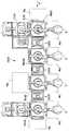
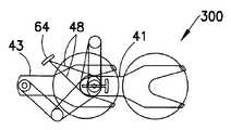
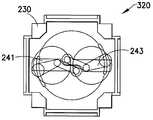
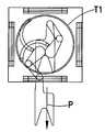
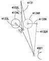
도 4a-c를 참조하면, 기판 이송 장치(300)는 예를 들어, 이중 동측 스카라 암들을 가지고 기계적 스위치 메카니즘을 포함한다(도 3a-b를 또한 참조). 이송 챔버(30)는 일반적으로 도 2에 도시된 챔버 모듈들(18B,18i)과 유사할 수도 있다. 도 4b 및 4c에서 가장 잘 알 수 있는 바와 같이, 이송 장치는 독립적으로 분절된 암들(A 및 B)을 포함할 수도 있으며, 이송 챔버(30) 내에 위치된다. 도 4b에서, 이중 동측 스카라 암들은 이송 챔버가 도시되지 않은, 암 A(41) 및 암 B(43)로서 표시된다. 이송을 위한 기판은 S로 표시되고, 포크형상의 엔드 이펙터(32)상의 위 치된다. 엔드 이펙터는 패들 형상을 포함하지만 이에 제한되지 않는 대체의 형상일 수도 있다. 하나의 엔드 이펙터가 예시를 위해 도시되며, 다른 실시예들에서, 암(들)은 임의의 수의 엔드 이펙터들을 가질 수도 있다. 기판 S이 대표적일 수도 있고, 200mm, 300mm, 450mm 또는 더 큰 반도체 웨이퍼, 플랫 스크린 디스플레이용 레티클, 펠리클 또는 패널과 같은 임의의 사이즈 및 형상일 수도 있다. 상술한 바와 같이, 각 암은 예를 들어, 스카라 배열을 가질 수도 있지만, 다른 실시예들에서는, 이송 암들은 임의의 다른 소정의 배열을 가질 수도 있다. 예시적인 실시예에서, 이송 암들은 일반적으로 유사하지만, 다른 실시예들에서는 암들은 상이할 수도 있다. 엔드 이펙터(32)가 각 암 A(41) 및 B(43)에 대한 포어암(36)에 리스트 조인트(34)에서 피벗하게 연결된다. 포어암(36)은 암 A(41) 및 암 B(43) 각각에 대한 상부 암(40)에 엘보우 조인트(38)에서 피벗하게 연결된다. 다른 실시예에서, 상부 암(40), 예를 들어, 암 A(41) 및 B(43)는 암 쇼울더 조인트(46)를 통해 T2 모터(44)에 대한 공통 베이스 회전자(42)에 차례로 탑재된다.Referring to FIGS. 4A-C, thesubstrate transfer device 300 has a mechanical switch mechanism, for example with double ipsilateral scalar arms (see also FIGS. 3A-B).Transfer chamber 30 may generally be similar tochamber modules 18B and 18i shown in FIG. 2. As best seen in FIGS. 4B and 4C, the transfer device may comprise independently segmented arms A and B and is located in thetransfer chamber 30. In FIG. 4B, the double ipsilateral scara arms are represented asarm A 41 andarm B 43, where the transfer chamber is not shown. The substrate for transfer is marked S and placed on thefork end effector 32. The end effector may be an alternative shape, including but not limited to a paddle shape. One end effector is shown for illustration, and in other embodiments, the arm (s) may have any number of end effectors. Substrate S may be representative and may be any size and shape, such as a 200mm, 300mm, 450mm or larger semiconductor wafer, a reticle, pellicle or panel for flat screen display. As mentioned above, each arm may have a scara arrangement, for example, but in other embodiments, the transfer arms may have any other desired arrangement. In an exemplary embodiment, the transfer arms are generally similar, but in other embodiments the arms may be different. Theend effector 32 is pivotally connected at the wrist joint 34 to theforearm 36 for eacharm A 41 andB 43. Theforearm 36 is pivotally connected at the elbow joint 38 to theupper arm 40 for each of thearms A 41 andB 43. In another embodiment, theupper arm 40, forexample arms A 41 andB 43, in turn, pass through the arm shoulder joint 46 to thecommon base rotor 42 for theT2 motor 44. Mounted.

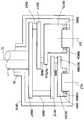
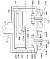
도 4d는 이송 장치(300)의 구동부 및 이송 챔버(30)의 개략적인 부분 입면도이다. 도 4d에서 알 수 있는 바와 같이, 예시적인 실시예에서, T1, T2 모터들은 임의의 적합한 타입의 모터들일 수도 있으며, 챔버(30)의 벽 구조내에 일체화될 수도 있다. 예를 들어, T1, T2 모터들은, 고정자 코일들이 벽들에 일체화되고 챔버(30)의 내부 대기로부터 분리된, 무브러시 DC 모터들(임의의 다른 적합한 모터들이 사용될 수도 있음)일 수도 있다. 다른 예시적인 실시예들에서, 구동부는 도 4e에 도시되고 아래에 더욱 상세히 설명하는 바와 같이 챔버(30) 아래에 적어도 부분 적으로 위치된 베어링 구동 시스템일 수도 있다. 다른 실시예들에서, 구동부는 예를 들어, 챔버 벽들에 위치된 구동부와 베어링 구동 시스템의 조합일 수도 있다. 다른 실시예들에서, 구동부는 여기에 개시된 구동 시스템과 임의의 적합한 종래의 구동 시스템의 임의의 조합일 수도 있다. 4D is a schematic partial elevation view of the drive and transferchamber 30 of thetransfer device 300. As can be seen in FIG. 4D, in an exemplary embodiment, the T1 and T2 motors may be any suitable type of motors and may be integrated into the wall structure of thechamber 30. For example, the T1 and T2 motors may be brushless DC motors (any other suitable motors may be used) with stator coils integrated into the walls and separated from the interior atmosphere of thechamber 30. In other exemplary embodiments, the drive may be a bearing drive system located at least partially below thechamber 30 as shown in FIG. 4E and described in more detail below. In other embodiments, the drive may be, for example, a combination of a drive and a bearing drive system located in the chamber walls. In other embodiments, the drive may be any combination of the drive system disclosed herein and any suitable conventional drive system.

다시 도 4d를 참조하면, 모터들은 도 4d에 도시된 바와 같이 Z 축 동작할 수 있는 공통부(302)에 하우징될 수도 있어서, Z 동작을 갖는 암들을 제공할 수도 있다. (벨로우 실들과 같은) 적합한 플렉시블 실들(SC)은 이송 챔버 모듈에서 분리가능한 대기를 유지하기 위해 구동 벨트를 인접하는 벽 구조에 연결할 수도 있다. 구동부는 도 4d에 실질적으로 예시된 적합한 Z-구동부(T3)에 동작가능하게 연결될 수도 있다. Z-구동부는 Z 방향에서 회전자들(42,50R)을 이동시킬 수 있는 고정자에서 권선들(미도시)을 포함하는 것과 같은, 임의의 적합한 타입일 수도 있다. 또한, 소정의 Z 위치에서 회전자들 및 암들을 홀딩하는 모터 회전자들 및 암들에 대한 Z 위치 제어, Z-안정성에 추가하여, Z-구동 권선들이 제공될 수도 있다. 모터들은 방사상 및 Z-방향들에서 셀프 베어링일 수도 있거나, Z 및 방사상 베어링에 대한 영구 자석들 또는 기계적 베어링들 또는 이들의 조합과 같은 패시브 방사상 및 Z 베어링 시스템들을 가질 수도 있다. 다른 실시예들에서, Z-구동부는 이송 암들의 Z-동작을 작동시키기 위해 섹션(302)에 연결된 리드 나사를 파워링하는 Z-구동 모터를 포함할 수도 있다. 다른 실시예들에서, 암들(41,43)의 쇼울더 조인트(46)는 동축이고, 각각의 상부 암들(40A,40B)은 회전의 모터 축(22)으로부터 오프셋될 수도 있는 공통 샤프트(24)에 대해 피벗한다. 다른 실시예들에서, 임들은 서로 실질적으로 평행한 회전의 대응하는 축에 대하여 각각 회전하는 오프셋 쇼울더 조인트들과 탑재될 수도 있다. 예시적인 실시예들에서, 모터 회전자들(42,50R)은, 예시를 위해 챔버(30)의 바닥 벽(30L)과 같은 일 측상에 위치되는 것으로 도시되지만, 다른 실시예들에서는, 회전자들은 (이송 암들 위의) 상부상의 일 회전자 및 (암들 아래의) 바닥상의 일 회전자와 같은, 이송 챔버 벽들중 하나 이상에 배치될 수도 있다. 예시적인 실시예에서, 회전자들은 중량 감소를 위해, 일반적인 중공 링 구조를 가질 수도 있다. 다른 실시예들에서, 회전자들은 임의의 적합한 형상 및 구성을 가질 수도 있다.Referring again to FIG. 4D, the motors may be housed in a common portion 302 capable of Z axis operation, as shown in FIG. 4D, to provide arms with Z operation. Suitable flexible seals (such as bellows seals) may connect the drive belt to the adjacent wall structure to maintain a detachable atmosphere in the transfer chamber module. The drive may be operably connected to a suitable Z-drive T3 substantially illustrated in FIG. 4D. The Z-drive may be of any suitable type, such as including windings (not shown) in the stator that can move therotors 42, 50R in the Z direction. Z-drive windings may also be provided in addition to Z position control, Z-stability for motor rotors and arms that hold the rotors and arms at a given Z position. The motors may be self bearing in radial and Z-directions or may have passive radial and Z bearing systems such as permanent magnets or mechanical bearings or a combination thereof for the Z and radial bearings. In other embodiments, the Z-drive may include a Z-drive motor that powers a lead screw connected to the section 302 to activate the Z-movement of the transfer arms. In other embodiments, theshoulder joint 46 of thearms 41, 43 is coaxial, and each of theupper arms 40A, 40B has acommon shaft 24 that may be offset from themotor shaft 22 of rotation. Pivot for In other embodiments, the Limes may be mounted with offset shoulder joints that each rotate about a corresponding axis of rotation substantially parallel to each other. In exemplary embodiments, themotor rotors 42, 50R are shown as being located on one side, such as thebottom wall 30L of thechamber 30 for illustrative purposes, while in other embodiments the rotor They may be disposed in one or more of the transfer chamber walls, such as one rotor on the top (above the transfer arms) and one rotor on the bottom (under the arms). In an exemplary embodiment, the rotors may have a general hollow ring structure, for weight reduction. In other embodiments, the rotors may have any suitable shape and configuration.

도 4b, 4d에서 가잘 잘 알 수 있는 바와 같이, 크랭크 링크(48)가 각 암 A(41) 및 B(43)에 대한 상부 암(40A,B)을 모터(50)의 회전자(50R)상의 회전 조인트(52)에 연결한다. 도 4a-d에 도시된 바와 같이, 2개의 크랭크 링크들은 모터(T1)의 회전자(50R)상에서 공통 컨버전트 또는 피벗 (예를 들어, 샤프트)(52)을 공유한다. 도 4a 및 4b에 예시된 평면도에서 가장 잘 알 수 있는 바와 같이, 각각의 상부 암들(40A,40B)에 대한 각 링크(48A,48B)의 회전 조인트들(20A,20B)의 위치들은 예를 들어, 각 암의 엔드 이펙터(32)가 펼쳐지고/접히는 X 축의 실질적으로 대향 측들상에 있다. 암 A(41) 또는 암 B(43)의 펼침을 작동시키기 위해 (예를 들어, 엔드 이펙터(32)상의 기판 S의 픽 및 플레이스를 위해), T1 모터(50)가 회전되는 동안 T2 모터(44)는 정지이다. 모터로부터 암들을 물리적으로 결합해제하지 않고 공통 모터에 의해 생성된 하나의 다른 암으로부터 하나의 암의 동작을 전개하는 기계적 스위치 또는 로스트 동작 시스템이라 칭할 수도 있기 때문에, T1 모터가 일 방향에서 회전될 때, 하나의 암은 펼쳐지거나 접히고 제 2 암은 실제로는 이동하지 않는다. 도 4c는 이송 챔버(30)의 경계를 넘어 펼쳐진 위치에서 암 A(41)을 도시하지만, 암 B는 이송 챔버(30)내에서 접힌다. 이러한 암 A(41)의 이동은 기판 S가 저장 챔버 또는 프로세싱 스테이션에서 픽업되고 플레이스되게 한다. 암들의 회전을 작동시키기 위해, T2 모터(44) 및 T1 모터(50) 모두는 동일한 정도로 회전된다. T1 모터(50) 및 T2 모터(44)는 T1의 회전 중심이 T2 로부터 오프셋되는 것을 필요로 하는 독립적인 구동 샤프트들을 갖는다.As can be seen in FIGS. 4B and 4D, thecrank link 48 has theupper arm 40A, B for eacharm A 41 andB 43 rotating therotor 50R of themotor 50. To the rotary joint 52 on the top. As shown in FIGS. 4A-D, the two crank links share a common convergence or pivot (eg, shaft) 52 on therotor 50R of the motor T1. As best seen in the top views illustrated in FIGS. 4A and 4B, the positions of therotary joints 20A, 20B of eachlink 48A, 48B relative to the respectiveupper arms 40A, 40B are for example. Theend effector 32 of each arm is on substantially opposite sides of the X axis where it is unfolded / folded. To activate the unfolding ofarm A 41 or arm B 43 (eg, for pick and place of substrate S on end effector 32), while theT1 motor 50 is being rotated, the T2 motor ( 44) is a stop. When a T1 motor is rotated in one direction, it may be referred to as a mechanical switch or lost operating system that develops the motion of one arm from one other arm generated by a common motor without physically disengaging the arms from the motor. For example, one arm is unfolded or folded and the second arm does not actually move. 4C showsarm A 41 in a deployed position beyond the boundaries oftransfer chamber 30, but arm B is folded withintransfer chamber 30. This movement ofarm A 41 causes substrate S to be picked up and placed in a storage chamber or processing station. To activate the rotation of the arms, both theT2 motor 44 and theT1 motor 50 are rotated to the same degree.T1 motor 50 andT2 motor 44 have independent drive shafts that require the center of rotation of T1 to be offset from T2.

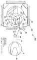
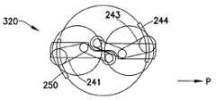
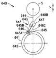
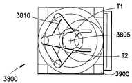
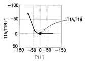
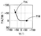
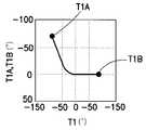
이제, 도 3a-b를 참조하여, 여기에 개시된 암 동작에 대한 기계적 스위치 메카니즘(10)의 동작 원리를, 동측 이중 암 구성에서 사용될 때 설명한다. 도 3a-b는 도 4a-4d에 도시된 동측 이중 스카라 암 구성의 기계적 스위치 메카니즘(10)을 도시한다. 인식될 수도 있는 바와 같이, 각각의 암들(40A,40B) 및 공통 모터(T1), 회전자(50R)에 대한 라인들 및 이들의 연결들은 실질적으로 서로 미러 이미지들이며, 그것의 동작을 명확히 예시하기 위해 도 3a-3b에 도시된 바와 같이 표현될 수도 있다. 상술한 바와 같이, 기계적 스위치 메카니즘(10)은 예시적인 실시예에서 공통 회전 조인트(24)를 공유하는 상부 암들(40A,40B)을 포함할 수도 있지만, 대향하는 회전 조인트들(24,24'), T1 모터 회전자(50R)상에 (직경 14를 갖는) 원형 부재들로서 도시되고, (공통) 회전 축(22)상에 (직경 12를 갖는) 대향하는 원형 부재들로서 도시된다. 이들 부재들은 링크들(48A,48B)의 각 측상에 위치된 (각각의 상부 암들에 대한) 회전 조인트들(18,18'), 조인트들(20A,20B)에서 크랭크 링크들(48A,48B)과 함께 링크될 수도 있다. 제한하지 않는 예시적인 베어링들(18,20) 은 니들 타입, 볼 베어링 타입 또는 부싱 타입을 포함한다. 예시적인 실시예에서, 회전자(50,50')의 회전의 중심(22) 및 (상부 암들) 원(40A,40B,24,24')의 회전의 중심(예를 들어, 쇼울더 조인트)은 예시적인 실시예에서 서로에 대해 오프셋될 수도 있다. 따라서, 도 3a에서 가장 잘 알 수 있는 바와 같이, 예시적인 실시예에서, 각 암(41,43)은 모터 회전자(50R,50R')를 나타내는 원(T1)을 이 예에서 대응하는 암들의 상부 암들(40A,40B)을 나타내는 더 작은 원(T2)과 결합하는 대응하는 크랭크 링크(48A,48B)를 가질 수도 있다. 다른 실시예들에서, 링크 결합 모터 및 분절된 암은 암의 임의의 다른 소정의 부(section)에 체결될 수도 있다.Referring now to FIGS. 3A-B, the operating principle of themechanical switch mechanism 10 for arm operation disclosed herein is described when used in an ipsilateral double arm configuration. 3A-B illustrate themechanical switch mechanism 10 of the ipsilateral dual scara arm configuration shown in FIGS. 4A-4D. As may be appreciated, therespective arms 40A, 40B and the common motor T1, the lines to therotor 50R and their connections are substantially mirror images of one another and clearly illustrate its operation. May be represented as shown in FIGS. 3A-3B. As noted above, themechanical switch mechanism 10 may includeupper arms 40A, 40B that share a common rotating joint 24 in an exemplary embodiment, but opposingrotating joints 24, 24 ′. , As circular members (with a diameter of 14) on theT1 motor rotor 50R, and as opposing circular members (with a diameter of 12) on the (common) axis ofrotation 22. These members are rotatingjoints 18, 18 ′ (for respective upper arms), cranklinks 48A, 48B at thejoints 20A, 20B located on each side of thelinks 48A, 48B. It can also be linked together.Non-limiting example bearings 18, 20 include a needle type, ball bearing type or bushing type. In an exemplary embodiment, the center ofrotation 22 of therotors 50, 50 ′ and the center of rotation of the (upper arms) circles 40A, 40B, 24, 24 '(eg, shoulder joints) are: It may be offset relative to each other in an exemplary embodiment. Thus, as best seen in FIG. 3A, in an exemplary embodiment, eacharm 41, 43 has a circle T1 representing themotor rotor 50R, 50R ′ in this example of the corresponding arms. It may have acorresponding crank link 48A, 48B that engages a smaller circle T2 representingupper arms 40A, 40B. In other embodiments, the link coupling motor and the segmented arm may be fastened to any other predetermined section of the arm.

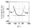
기계적 스위치(10)를 통해 모터 T1(50)에 의해 작동된 암들 A,B(41,43)의 결과적인 동작들이, T1이 0과 -135도 사이에서 (반시계 방향) 회전하고, 암 A(41)가 (쇼울더(24)에 대해) 펼침 각을 변화하거나 회전할 때 예로서 도 3b에 실질적으로 도시된다. 반대로, 암 B(43)는 실제로 이동하지 않는다. 그러나, T1이 0과 +135도 사이에서 (시계 방향) 회전할 때, 암 B는 (쇼울더(24)에 대해) 펼침 각을 변화하거나 회전하며, 암 A는 실제로 이동하지 않는다. 예시적인 실시예에서의 스위치의 동작을 예시하는 상대적 운동들이 암들 (A 및 B) 의 펼침 각 대 T1의 방향을 도시하는 도 3b의 그래프에 그래프적으로 또한 도시된다. 상술한 바와 같이, 예시적인 실시예에서, 2개의 크랭크 링크들(48A, 48B)는 대칭 축의 반대에 부착될 수도 있어서, T1이 일 방향에서 회전할 때, 하나의 링크 및 암 조합이 실질적으로 락되어서, 이것은 T1 및 다른 링크와의 암 회전 및 암 조합이 실질적으로 릴리즈되거나 자유롭게 하여서 T1에 의한 이동을 경험하지 않는다. 대응하게는, T1이 대향하는 방향에서 회전할 때, 이전에 락된 암은 릴리즈되어 T1으로 회전하고, 이전에 자유로운 암은 실질적으로 락되어 T1으로 회전한다. 이것은 단지 하나의 모터(T1)로부터 (회전의 방향 및 정도에 의존하여) 2개의 암들의 독립적 펼침을 허용한다. 인식될 수도 있으며 이하 더욱 상세히 설명하는 바와 같이, T1 및 T2 모두가 함께 회전할 때, 2개의 암들은 예를 들어, 이송 챔버(30)에 대해 (예를 들어, 회전의 중심(22)에 대해) 일 유닛으로서 상대적으로 회전한다.The resulting actions of arms A, B (41, 43) actuated by motor T1 (50) via mechanical switch (10) rotate T1 between 0 and -135 degrees (counterclockwise),arm A 41 is substantially shown in FIG. 3B as an example when changing or rotating the spread angle (relative to shoulder 24). In contrast,arm B 43 does not actually move. However, when T1 rotates (clockwise) between 0 and +135 degrees, arm B changes or rotates the spread angle (relative to shoulder 24), and arm A does not actually move. Relative movements illustrating the operation of the switch in the exemplary embodiment are also shown graphically in the graph of FIG. 3B showing the direction of spreading T1 versus arms A and B. FIG. As mentioned above, in the exemplary embodiment, the two cranklinks 48A, 48B may be attached opposite the axis of symmetry such that when T1 rotates in one direction, one link and arm combination is substantially locked. In this way, arm rotation and arm combinations with T1 and other links are substantially released or freed so that they do not experience movement by T1. Correspondingly, when T1 rotates in the opposite direction, the previously locked arm is released and rotates to T1, and the previously free arm is substantially locked to rotate to T1. This allows independent unfolding of the two arms (depending on the direction and degree of rotation) from only one motor T1. As may be appreciated and described in more detail below, when both T1 and T2 rotate together, the two arms are for example relative to the transfer chamber 30 (eg, relative to the center ofrotation 22). ) Rotate relatively as a unit.

도 3a 및 도 4a-4d로부터 알 수 있듯이, 본 실시예에서, T1, T2 모터들(42, 50)은 무축의 구동 커플링 시스템이라 지칭될 수 있는 것을 통하여 각각의 암들 A, B(41, 43)에 결합되는 (전술한 바와 같이 브러시가 없는 DC 모터들과 같은) 로터리 모터들(rotary motor)일 수 있다. 본 실시예에서, T1 및 T2 모터들의 고정자들(50S, 44S)은 이송 챔버(30)의 외주를 따라 근방에서 일반적으로 아치형과 같이 대체로 선형적으로 안배될 수 있다. T1, T2 모터들의 직경은 이송 챔버의 공간 엔벨로프와 대비하여 최대화될 수 있으며, 이로부터 알 수 있는 바와 같이, 이송 챔버의 공간 엔벨로프는 상기 암들의 하나 이상의 엔드 이펙터(들) 상에 암들 A, B 및 웨이퍼들의 이동을 위한 유격들을 둘러싸는 공간 엔벨로프까지 최소화된다. 알 수 있는 바와 같이, 본 실시예에서, 예를 들면, T1 모터는 회전의 쇼울더 축에 편심되는 암들 A, B에 힘을 인가하도록 동작하며, 이로 인하여, 예로서, T1 모터 50의 출력은 예를 들면, 쇼울더 조인트(24)에 의해 한정되는 펄크럼(fulcrum) 주위로 상기 암들을 피봇시키는 암들 A, B 내에 레버리지 힘을 인가한다. 전술한 바와 같이 기계적 스위치(10)을 포함하는 암들과 모터(50) 사이의 커플링 시스템은 모 터(50)에 의해 회전의 쇼울더 축에 편심인 암들에 인가될 수 있는 힘을 결과적으로 발생시킨다. 다른 실시예들에서, 상기 모터들 및 상기 모터로부터 상기 암으로 힘을 전달하는 커플링들은 다른 적합한 구성을 가질 수도 있다.As can be seen from FIGS. 3A and 4A-4D, in this embodiment, the T1,T2 motors 42, 50 are each arm A, B (41, through) which may be referred to as a shaftless drive coupling system. 43 may be rotary motors (such as brushless DC motors as described above). In this embodiment, thestators 50S, 44S of the T1 and T2 motors may be arranged generally linearly, such as generally arcuate, near the perimeter of thetransfer chamber 30. The diameter of the T1, T2 motors can be maximized in contrast to the spatial envelope of the transfer chamber, and as can be seen, the spatial envelope of the transfer chamber has arms A, B on one or more end effector (s) of the arms. And a spatial envelope surrounding the play for movement of the wafers. As can be seen, in this embodiment, for example, the T1 motor operates to apply force to arms A, B eccentric to the shoulder axis of rotation, whereby, for example, the output of theT1 motor 50 is yes. For example, a leverage force is applied in arms A and B that pivot the arms around a fulcrum defined byshoulder joint 24. As described above, the coupling system between themotor 50 and the arms comprising themechanical switch 10 results in a force that can be applied by themotor 50 to the arms eccentric to the shoulder axis of rotation. . In other embodiments, the motors and couplings that transfer force from the motor to the arm may have another suitable configuration.

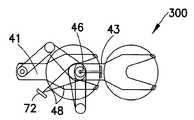
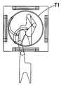
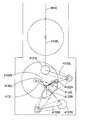
도 5a-5d는 본 명세서에 개시된 기계적 스위치 메커니즘을 포함하는 듀얼 동측 스카라 암들을 갖는 기판 이송 장치에 대하여 4 개의 다른 펼침 위치들에 있는 암 A(41)의 펼침 운동을 도시한다. 도 5a에서, T2 모터 마운팅 플레이트 44 상의 암 쇼울더 조인트들(46)을 T1 모터(50)에 연결하는 2 개의 크랭크 링크들(48)은 전술한 바와 같이, T1(50)의 외주를 따라 (도 4,d의 조인트(52)와 유사하게) 외선 조이트(62)에서 실질적으로 수렴하지만, 다른 실시예에서, 상기 링크들은 오프셋된 외선 조인트들에서 T1 모터(50)의 로터에 체결될 수도 있다. T1 모터(50)의 로터(50R)이 시계 방향으로 회전할 때, 크랭크 링크들(48A, 48B)도 도 5b의 지점(62)로부터 지점 B(64)까지 T1의 외주를 따라 회전하며, 이에 의해, 이번에는, 암 (41)이 우측 방향으로 바깥쪽으로 펼쳐지고, 암 B(3)은 접힘 위치에서 실질적으로 고정된 채로 있게 된다. T1(50)이 시계 방향으로 더 회전함에 따라, 크랭크 링크들(48)은 도 5c의 지점 C(66)까지T1의 외주를 따라 더 회전하며, 이에 의해, 이번에는, 암 A(41)이 우측을 향하여 바깥쪽으로 더 펼쳐지지만, 암 B(43)은 접힘 위치에서 실질적으로 고정된 채로 남게 된다. T1(50)이 시계 방향으로 더 회전함에 따라, 크랭크 링크들(48)은 도 5c의 지점 C(66)까지 T1의 외주를 따라 더 회전하며, 이에 의해, 이번에는, 암 A(41)이 우측을 향하여 바깥쪽으로 더 펼쳐지고, 암 B(43)은 접힘 위치에서 실질적으로 고정된 채로 남게 된다. T1(50)이 시계 방향으 로 더 회전함에 따라, 크랭크 링크들(48)은 도 5d의 지점 D(68)까지 T1의 외주를 따라 더 회전하며, 이에 의해 이번에는 암 A(41)가 우측 방향으로 바깥쪽으로 더 펼쳐지면서 암 B(43)는 접힘 위치에서 실질적으로 고정된 채로 여전히 남아있게 된다. 암 A(41)를 접기 위하여 T1(50)의 방향은, 지점들 C(66), B(64) 및 A(62)를 따라 역전된다. 다른 실시예에서 2 개의 암들(41, 43)을 위한 2 개의 크랭크 링크들(48)은 T1(50)의 외주상의 동일 지점상에 수렴될 필요가 없다.5A-5D illustrate the unfolding movement ofarm A 41 in four different unfold positions relative to a substrate transfer device having dual ipsilateral scara arms including the mechanical switch mechanism disclosed herein. In FIG. 5A, the two cranklinks 48 connecting thearm shoulder joints 46 on the T2motor mounting plate 44 to theT1 motor 50 are along the outer periphery ofT1 50, as described above (FIG. Similarly to the joint 52 of 4, d), substantially converging at theouter join 62, but in other embodiments, the links may be fastened to the rotor of theT1 motor 50 at offset outer joints. . When therotor 50R of theT1 motor 50 rotates clockwise, the crank links 48A, 48B also rotate along the outer periphery of T1 frompoint 62 to pointB 64 in FIG. 5B, whereby By this time, thearm 41 is spread outward in the right direction, and thearm B 3 remains substantially fixed in the folded position. AsT1 50 rotates further clockwise, cranklinks 48 further rotate along the perimeter of T1 to pointC 66 in FIG. 5C, wherebyarm A 41 is rotated this time. While further spread outwards to the right,arm B 43 remains substantially fixed in the folded position. AsT1 50 rotates further clockwise, cranklinks 48 further rotate along the perimeter of T1 to pointC 66 in FIG. 5C, wherebyarm A 41 is rotated this time. Further spread outwards to the right,arm B 43 remains substantially fixed in the folded position. AsT1 50 rotates further clockwise, cranklinks 48 further rotate along the periphery of T1 to pointD 68 of FIG. 5D, wherebyarm A 41 now turns to the right. Unfolding further outward in the direction,arm B 43 remains substantially fixed in the folded position. The direction ofT1 50 is reversed alongpoints C 66,B 64 and A 62 to foldarm A 41. In another embodiment the two cranklinks 48 for the twoarms 41, 43 need not converge on the same point on the outer circumference of theT1 50.

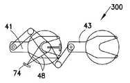
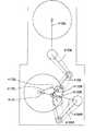
도 6a-6c는 본 명세서에 개시된 기계적 스위치 메커니즘을 포함하는 듀얼 동측 스카라 암들을 갖는 기판 이송 장치(300)에 대하여 3 개의 서로 다른 펼침 위치에 있는 암 B(43)의 펼침 운동을 도시한다. 도 6a에서, T2 모터 로터(44) 상의 지지되는 암 쇼울더 조인트(46)를 T1 모터에 연결하는 2 개의 크랭크 링크들(48)은 예(50)에 따라, 예를 들면, T1 모터(50)의 외주를 따르는 지점 E(72)에 위치한다. T1 모터(52)가 반시계 방향으로 회전함에 따라, 크랭크 링크들(48)도 도 6b의 지점 F(74)까지 T1의 외주를 따라 회전하며, 이에 의해 이번에는 암 B(43)가 우측 방향으로 바깥쪽으로 펼쳐지고, 암 A(41)는 접힘 위치에서 실질적으로 고정된 채로 남아있는다. T1(50)이 반시계 방향으로 더 회전함에 따라 크랭크 링크들(48)은 도 6c의 지점 G(76)까지 T1의 외주를 따라 더 회전하며, 이에 의해 이번에는 암 B(43)가 우측 방향으로 바깥쪽으로 더 펼쳐지고, 암 A(41)는 접힘 위치에서 실질적으로 고정된 채로 여전히 남아있는다. 암 B(43)를 접기 위하여 T1(50)의 방향은 지점들 F(74) 및 E(72)를 따라 역전된다.6A-6C illustrate the unfolding motion ofarm B 43 in three different unfolded positions relative to thesubstrate transfer device 300 having dual ipsilateral scara arms including the mechanical switch mechanism disclosed herein. In FIG. 6A, the two cranklinks 48 connecting the supported arm shoulder joint 46 on theT2 motor rotor 44 to the T1 motor are in accordance with example 50, for example, theT1 motor 50. Is located atpoint E 72 along the perimeter of. As theT1 motor 52 rotates counterclockwise, the crank links 48 also rotate along the periphery of T1 to pointF 74 in FIG. 6B, wherebyarm B 43 is now in the right direction. Outwards,arm A 41 remains substantially fixed in the folded position. AsT1 50 further rotates counterclockwise, cranklinks 48 further rotate along the perimeter of T1 to pointG 76 of FIG. 6C, wherebyarm B 43 now rotates in the right direction. Further outwardly,arm A 41 remains substantially fixed in the folded position. The direction ofT1 50 reverses alongpoints F 74 andE 72 to foldarm B 43.

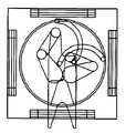
도 7a-7e는 기판 이송 장치(300)의 5 개의 서로 다른 회전 위치에 있는 암 A(41) 및 암 B(43)의 회전 운동을 도시한다. 도 7a에서 엔드 이펙트(들)(32)는 양의 x축을 따라 가리킨다. T1 및 T2 모터들(50, 44)은 모두 동일 방향으로 동일 양만큼 회전할 때, 암들 A 및 B(41, 43)는 이에 대응하여 동일 방향으로 도 7b, 7c, 7d 및 7e에 도시된 컨티넘을 따라 회전축(22) 주위로 일 단위로서 회전한다.7A-7E illustrate the rotational movement ofarm A 41 andarm B 43 in five different rotational positions of thesubstrate transfer device 300. In FIG. 7A the end effect (s) 32 point along the positive x axis. When both the T1 andT2 motors 50, 44 rotate by the same amount in the same direction, the arms A andB 41, 43 correspondingly have the contiguity shown in FIGS. 7B, 7C, 7D and 7E in the same direction. It rotates as a unit around the rotatingshaft 22 along the over.

도 8a-8c은 암 A(41)의 대응되는 위치들에 따르는 3 개의 서로 다른 예시적인 위치들에서의 본 실시예에 따른 암 B(43)의 펼침/접힘 운동을 도시한다. 알 수 잇는 바와 같이, 도 8a의 실시예에서, 암 B는 펼침 위치에 있고, 도 8c에서, 암(8)은 접힘 위치에 있다. 도 8a에서, T2 모터 마운팅 플레이트(44) 상의 암 쇼울더들(42)을 T1 모터(50)에 연결시키는 2 개의 크랭크 링크들(48)을 위한 외선 조이트는 T1 모터(50)의 외주를 따라 지점 H(82)에 배치된다. T1 모터(50가, 예를 들면, 시계 방향으로 회전함에 따라, 크랭크 링크들(48)도 T1의 외주를 따라 도 8b의 지점 I(84)까지 회전하며, 이에 의해, 이번에는, 암 B(43)가 좌측으로 내부를 향하여 접히고, 암 A(41)는 접힘 위치에서 실질적으로 정적으로 남게 된다. T1(50)이 시계 방향으로 더 회전할 수록, 크랭크 링크들(48)은 T1의 외주를 따라 도 8c의 지점 J(86)까지 더 회전하고, 이에 의하여, 이번에는, 암 B(43)가 우측 방향으로 내부로 더 접히고, 암 A(41)은 여전히 접힘 위치에서 실질적으로 고정된 채로 남아 있게 된다.8A-8C show the spreading / folding motion ofarm B 43 according to this embodiment in three different exemplary positions along the corresponding positions ofarm A 41. As can be seen, in the embodiment of FIG. 8A, arm B is in the extended position and in FIG. 8C, arm 8 is in the folded position. In FIG. 8A, the outer tightening for the two cranklinks 48 connecting the arm shoulders 42 on the T2motor mounting plate 44 to theT1 motor 50 is pointed along the outer periphery of theT1 motor 50. Disposed atH 82. As theT1 motor 50 rotates, for example clockwise, the crank links 48 also rotate along the outer periphery of T1 to point I 84 of FIG. 8B, whereby this time arm B ( 43 is folded inward to the left, andarm A 41 remains substantially static in the folded position.The more theT1 50 rotates clockwise, the more the crank links 48 are in the outer periphery of T1. Further along to pointJ 86 of FIG. 8C, whereby thistime arm B 43 is further folded inward in the right direction andarm A 41 is still substantially fixed in the folded position. Will remain.

도 5a-5d, 6a-6c, 7a-7e 및 8a-8c에 도시된 동작은 단지 2 개의 모터들(T1 및 T2)이 본 명세서에 개시된 기계적 스위치 메카니즘(mechanical switch mechanism)을 통하여 각 암의 실질적으로 독립적인 펼침/접힘을 기동시키거나 듀얼 동측형 스카라 암들(dual same side SCARA arms)의 회전을 동작시킬 수 있다. 이와 달리, 표준 듀얼 동측형 스카라 암들은 상기 2 개의 암들의 펼침/접힘 및 회전을 동작시키기 위하여 3 개의 모터들이 필요하다. 따라서, 본 명세서에 개시된 기계적 스위치 메카니즘에 의하여, 하나의 모터를 생략하는 것이 가능하고, 그에 따른 비용 절감과 공간 감소의 이득을 얻을 수 있다.The operations shown in FIGS. 5A-5D, 6A-6C, 7A-7E, and 8A-8C show that only two motors (T1 and T2) can be used substantially through the mechanical switch mechanism disclosed herein. Can be used to activate independent unfolding / folding or to rotate the rotation of the dual same side SCARA arms. In contrast, standard dual ipsilateral scara arms require three motors to operate the spreading / folding and rotation of the two arms. Therefore, by the mechanical switch mechanism disclosed in this specification, it is possible to omit one motor, whereby a cost reduction and a space reduction benefit can be obtained.

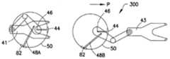
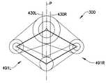
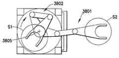
구현된다면, 엔드 에펙터, 포어 암들 및 어퍼 암들은 싱크로(synchro) 시스템에 의하여 링크되어, 쇼울더부의 외선 조인트(revolute joint) 주위로 어퍼 암의 회전이 어퍼 암과 포어 암들 사이, 그리고 포어 암들과 엔드 이펙터 사이의 상대적 운동을 발생시키며, 그 결과, 상기 암의 펼침/접힘은 엔드 이펙터가, 도 9a에 도시된 축 P와 같은 이동 축을 따라 이동하도록 한다. 도 9a-9c는 하기의 예시적인 실시예에 따라 3 개의 다른 펼침 위치에 있는 듀얼 동측형 스카라 암들 또는 암 조립체들을 위한 예시적인 싱크로 시스템을 도시한다. 기판 이송 장치(300)는 구동부 (모터들 T1 및 T2 는 미도시), 상기 구동부 사이의 커플링 시스템, 및 암들 또는 암 조립체들(491L, 491R)을 포함할 수 있다. 본 실시예에서, 2 개의 스카라 암 조립체를 갖는 기판 이송(300)이 도시되었지만, 다른 실시예에서, 상기 기판 이송은 적합한 개수 및/또는 구성의 암 조립체들을 갖는 임의의 적합한 구성을 가질 수 있다. 도 3-8에서 전술한 바와 같은 상기 구동부 및 커플링 시스템은 사기 구동부의 2 개의 구동 모터들 T1 및 T2 가 서로에 대하여 하나 이상의 스카라 암의 펼침/접힘 및 회전을 실질적으로 독립적으로 동작시킬 수 있으며, 본 명세서에서 기계적 스위치 메카니즘이라 지칭되는 것을 포함하거나 정의한다. 상기 T1 및 T2 모터들 은 진공의 외부에 존재할 수도 있는 이송 챔버 벽들 내에 일체화되는 고정자 권선들(stator windings)에 결합되는 2 개의 적층된 링들 (로터들)로 이루어진다. 또한, 상기 어퍼 암 쇼울더를 이송 챔버의 중심 축외로 위치시킴으로써 종래의 스카라 암 설계와 비교시 상당히 작아진 암들로 SEMI를 달성할 수 있다.If implemented, the end effector, the forearms and the upper arms are linked by a synchro system such that rotation of the upper arm around the shoulder joint's revolute joint is between the upper arm and the forearm arms, and the forearm and the end arm. Relative motion between effectors occurs, and as a result, the arm's spreading / folding causes the end effector to move along a moving axis, such as axis P shown in FIG. 9A. 9A-9C illustrate an exemplary synchro system for dual ipsilateral scara arms or arm assemblies in three different extended positions, according to the following exemplary embodiment.Substrate transport apparatus 300 may include a drive (motors T1 and T2 are not shown), a coupling system between the drive, and arms orarm assemblies 491L, 491R. In this embodiment, asubstrate transfer 300 with two scara arm assemblies is shown, but in other embodiments, the substrate transfer may have any suitable configuration with an appropriate number and / or configuration of arm assemblies. The drive and coupling system as described above in FIGS. 3-8 allow the two drive motors T1 and T2 of the fraudulent drive to operate independently of the spreading / folding and rotation of one or more scara arms relative to each other. It includes, or defines, what is referred to herein as a mechanical switch mechanism. The T1 and T2 motors consist of two stacked rings (rotors) that are coupled to stator windings integrated in transfer chamber walls that may be external to the vacuum. In addition, by positioning the upper arm shoulder out of the center axis of the transfer chamber, SEMI can be achieved with arms that are significantly smaller compared to conventional scara arm designs.

다시 도 9a-9c를 참조하면, 일 실시예에서, 암들(491L 및 491R)은 이송 장치(3000)의 암들 A, B(41, 43)과 실질적으로 유사하며, 어퍼 암 부재(490L, 490R), 포어 암 부재(460L, 460R), 및 각각의 외선 조인트들(492, 493, 494 및 495)에 의해 서로 연결된 엔드 이펙터(430L, 430R)를 포함한다. 다른 실시예들에서, 상기 암들은 소정 개수의 분절들을 가질 수도 있다. 실시예에서, 어퍼 암들(490L 및490R)은 외선 조인트들(402, 401) (예를 들면, 쇼울더 조인트 24, 도 4a-4d 참조)을 축으로 회전한다. 어퍼 암들(490L, 490R)의 인접하는 단부들은 상기한 바와 같이 외선 조인트들(404, 406)에 의해 커플링 시스템의 링크들(422L, 422R)에 피봇 가능하게 체결된다. 어퍼 암들(490L, 490R)의 디스털(distal) 단부들은, 예를 들면, 외선 조인트들(492, 493)에서 포어 암들(460L, 460R)의 각각의 인접하는 단부들에 피봇 가능하게 체결된다. 엔드 이펙터들(460L, 460R)은 엔드 이펙트의 전방부로부터 엔드 이펙터의 후방부로 연장되는 세로축을 갖는다. 상기 엔드 이펙터들의 세로축은 도 3-8을 참조하여 상기한 바와 같이, 암들의 펼침 및 접힘 경로 P에 정렬될 수 있다. 다른 실시예들에서, 상기 암들은 펼침/접힘의 축 P에 대하여 소정의 구성을 가질 수 있다.Referring again to FIGS. 9A-9C, in one embodiment,arms 491L and 491R are substantially similar to arms A,B 41, 43 of transfer device 3000, andupper arm members 490L, 490R. And endeffectors 430L and 430R connected to each other byfore arm members 460L and 460R and respectiveouter joints 492, 493, 494 and 495. In other embodiments, the arms may have a certain number of segments. In an embodiment, theupper arms 490L and 490R rotate about theouter joints 402, 401 (egshoulder joint 24, see FIGS. 4A-4D). Adjacent ends of theupper arms 490L and 490R are pivotally fastened to links 422L and 422R of the coupling system by outer joints 404 and 406 as described above. Distal ends of theupper arms 490L and 490R are pivotally fastened to respective adjacent ends of theforearms 460L and 460R, for example, in theouter joints 492 and 493. Theend effectors 460L, 460R have a longitudinal axis that extends from the front of the end effect to the rear of the end effector. The longitudinal axis of the end effectors may be aligned with the unfolding and folding path P of the arms, as described above with reference to FIGS. 3-8. In other embodiments, the arms may have a predetermined configuration with respect to axis P of spreading / folding.

본 실시예에서, 상기 커플링 시스템의 링크들(48A, 48B; 도 3-8 참조)은 각 각 어퍼 암들(490L, 490R)의 내부로 삽입되거나 일부가 되어, 링크들(423L, 423R) 은 상기한 바와 같이 그들 각각의 암의 일부 또는 펼침을 제공한다. 다른 실시예들에서, 상기 암들은 임의의 적합한 방식으로 어퍼 암 부분들(423L, 423R)을 포함하도록 구성될 수 있다. 또한, 상기한 바와 같이, (모터 T2에 장착되는) 외선 조인트들(402, 401)은 각각 어퍼 암들(490L, 490R)의 피봇 지점들일 수 있다. 다른 실시예들에서, 어퍼 암 부분들(423L, 423R)은 상기 어퍼 암에 장착되는 풀리 또는 디스크에 연결되어, 각각의 디스크가 지점(402 또는 401) 주위로 회전하며, 이로써, 각각의 어퍼 암(491L, 491R)이 회전한다. 또 다른 실시예들에서, 상기 어퍼 암 부분들은 상기 어퍼 암에 토크를 인가하기 위한 암의 어떤 부분에 종속될 수도 있다. 구현되는 경우, 도 9a-9c에 도시된 바와 같이 어퍼 암의 다른 부분들에 대한 어퍼 암 부분들(423L, 423R)의 관계 또는 배향은 예시적일 뿐, 어퍼 암 부분들 423L, 423R은 상기 어퍼 암에 대하여 임의의 적합한 관계/배향을 가질 수 있다.In this embodiment, thelinks 48A, 48B (see FIGS. 3-8) of the coupling system are inserted into or become part of theupper arms 490L, 490R, respectively, so that the links 423L, 423R are It provides a portion or spread of their respective arms as described above. In other embodiments, the arms may be configured to include upper arm portions 423L, 423R in any suitable manner. In addition, as described above, theouter joints 402 and 401 (mounted to the motor T2) may be pivot points of theupper arms 490L and 490R, respectively. In other embodiments, upper arm portions 423L and 423R are connected to a pulley or disk mounted to the upper arm such that each disk rotates aroundpoint 402 or 401, thereby each upper arm. 491L and 491R rotate. In still other embodiments, the upper arm portions may be dependent on any portion of the arm for applying torque to the upper arm. If implemented, the relationship or orientation of the upper arm portions 423L, 423R to the other portions of the upper arm as shown in FIGS. 9A-9C is exemplary only, and the upper arm portions 423L, 423R are shown in the upper arm. It may have any suitable relationship / orientation for.

또한, 도시된 실시예에서, 암들(491L, 491R)은 상기 포어 암을 구동하기 위한 벨트 및 풀리 시스템을 포함할 수 있다. 예를 들면, 풀리들 435L, 435R은 (예를 들면, 도 4d에 도시된 바와 같이, 포스트 24에 고정된) 조인트들 402, 401에서 (고정된 또는 정적인) 고정체(fixture) 또는 허브에 결합되어, 어퍼 암들이 회전할 때, 이들의 각 풀리들(435L, 435R)은 상기 장치 프레임 대비 정적으로 남게 된다(예를 들면, 어퍼 암 운동은 어퍼 암과 대응되는 풀리 사이의 상대적인 운동에 영향을 미친다). 제 2 (아이들러; idler) 풀리(445L, 445R)은 조인트들(492, 493) 주위로 포어 암들(460L)에 결합될 수 있다. 풀리들(435L, 445R 및 435L, 445R)은 어퍼 암들(490L, 490R)이 회전할 때 풀리들(435L, 435R)에 대한 상대적인 운동에 의해 풀리들(445L, 445R)이 상기 벨트들을 통하여 회전 구동되도록 임의의 적합한 벨트 또는 밴드들(440L, 440R)에 의해 연결될 수 있다. 다른 실시예들에서, 상기 풀리들은 상기 풀리들에 핀 고정되거나 이와 다르게 고정된 하나 이상의 금속 밴드들에 의해 연결될 수 있다. 또 다른 실시예들에서, 상기 풀리들은 임의의 적합한 방식으로 연결되거나 다른 적합한 트랜스미션 시스템이 이용될 수도 있다. 상기 풀리들(435L, 435R, 445L, 445R)은 상기 암 부재들의 운동을 제한하여 조인트들(402, 401) 주위로의 어퍼 암들(490L, 490R)의 회전이 포어 암들(460L, 460R)의 각 암에 대하여 반대 방향으로 소정의 회전을 기동시키도록 구성될 수 있다. 예를 들면, 이러한 회전 관계를 얻기 위하여, 플리들(450L, 450R)대 풀리들(445L, 445R)의 라디언(radii)의 비율은 2:1일 수 있다.In addition, in the illustrated embodiment,arms 491L and 491R may include a belt and pulley system for driving the fore arm. For example, pulleys 435L, 435R may be attached to a fixture (fixed or static) or hub atjoints 402, 401 (eg, fixed to post 24, as shown in FIG. 4D). In combination, when the upper arms rotate, theirrespective pulleys 435L, 435R remain static relative to the device frame (e.g., upper arm movement affects the relative movement between the upper arm and the corresponding pulley). Crazy). Second (idler) pulleys 445L and 445R may be coupled tofore arms 460L aroundjoints 492 and 493.Pulleys 435L, 445R and 435L, 445R are driven by thepulleys 445L, 445R to rotate through the belts by relative motion to thepulleys 435L, 435R as theupper arms 490L, 490R rotate. May be connected by any suitable belt orbands 440L, 440R. In other embodiments, the pulleys may be connected by one or more metal bands pinned or otherwise secured to the pulleys. In still other embodiments, the pulleys may be connected in any suitable manner or other suitable transmission system may be used. Thepulleys 435L, 435R, 445L, 445R limit the movement of the arm members such that rotation of theupper arms 490L, 490R around thejoints 402, 401 causes the angle of theforearms 460L, 460R to rotate. It may be configured to activate a predetermined rotation in the opposite direction with respect to the arm. For example, to obtain this rotational relationship, the ratio of radii of thepleats 450L and 450R to thepulleys 445L and 445R may be 2: 1.

본 실시예에서, 제 2 벨트 및 풀리들(450L, 450R, 465L, 465R)을 포함하는 풀리 구성 및 벨트들(455L, 455R)은 엔드 이펙터들(430L, 430R)을 구동하여, 경로 P의 공통 경로를 따르는 엔드 이펙터들(430L, 430R)의 지름 방향의 배향 또는 길이 방향의 축이 암들(491L, 491R)이 펼쳐지고 접힐 때에 유지되도록 제공될 수 있다. 풀리들(450L, 450R)은 조인트들(492, 493) 주위로 이들 각각의 엔드 이펙터들(430L, 430R)에 결합될 수 있다. 본 실시예에서, 풀리들(465L, 465R)에 대한 풀리들(450L, 450R)의 비는 1:2 일 수 있다. 도 9a-9c에 도시된 바와 같이, 본 실시예의 풀리들(450L, 450R)은 조인트들(492, 493) 주위의 풀리들(445L, 445R)의 각각에 나란하게 탑재되어, 풀리들(445L, 445R)이 포어 암들(460L, 460R)과 함께 회전 할 때, 풀리들(450L, 450R)이 이들의 각 어퍼 암들(490L, 490R)에 대하여 정적으로 남게 된다. 임의의 적합한 벨트(455L, 455R)가 상기 풀리들의 각 쌍을 연결하여, 포어 암들(460L, 460R)이 회전할 때, 풀리들(465L, 465R)도 회전 구동된다. 다른 실시예들에서, 상기 풀리들은 상기 풀리들에 핀 고정되거나 다른 방식으로 고정된 하나 이상의 금속 밴드들에 의해 연결될 수 있다. 다른 실시예들에서는, 임의의 가요성 밴드가 상기 풀리들을 연결할 수도 있다. 또 다른 실시예들에서는, 상기 풀리들은 다른 적합한 방식으로 연결될 수도 있다.In this embodiment, the pulley configuration including the second belt and pulleys 450L, 450R, 465L, and 465R and thebelts 455L and 455R drive theend effectors 430L and 430R, so that the path P is in common. A radial orientation or longitudinal axis of theend effectors 430L, 430R along the path may be provided to be maintained when thearms 491L, 491R are unfolded and folded.Pulleys 450L and 450R may be coupled to theirrespective end effectors 430L and 430R aroundjoints 492 and 493. In the present embodiment, the ratio of thepulleys 450L and 450R to thepulleys 465L and 465R may be 1: 2. 9A-9C, thepulleys 450L and 450R of the present embodiment are mounted side by side on each of thepulleys 445L and 445R around thejoints 492 and 493, so that thepulleys 445L, When 445R rotates withpore arms 460L and 460R, pulleys 450L and 450R remain static with respect to their respectiveupper arms 490L and 490R. Anysuitable belt 455L, 455R connects each pair of pulleys so that when thefore arms 460L, 460R rotate, thepulleys 465L, 465R are also rotationally driven. In other embodiments, the pulleys may be connected by one or more metal bands pinned or otherwise secured to the pulleys. In other embodiments, any flexible band may connect the pulleys. In still other embodiments, the pulleys may be connected in another suitable manner.

엔드 이펙터들(430L, 430R)은 외선 조인트(494, 495)에서 각 포어 암에 결합될 수 있다. 엔드 이펙터들(430L, 430R)은 풀리들(465L, 465R)의 각각에 구동가능하게 결합되어, 상기 암들이 펼쳐지거나 접힐 때에, 엔드 에펙터들(430L, 430R)은 도 9b, 9c에 도시된 바와 같이 이동(travel) P의 공통 경로와 길이 방향으로 정렬된다. 본 명세서에 개시된 상기 벨트 및 풀리 시스템들은 실제 응용시 생성된 임의의 파티클들이 암 조립체들 내에 포함될 수 있도록 암 조립체들(491L, 491R) 내에 하우징될 수 있다. 또한, 입자들이 기판들을 오염시키는 것을 방지하기 위해서, 적합한 배기/진공 시스템이 더 이용될 수도 있다. 다른 실시예들에서, 동기화 시스템(synchronization)은 상기 암 조립체의 외부에 위치할 수도 있다. 또 다른 실시예들에서, 상기 동기화 시스템은 임의의 적합한 위치에 배치될 수도 있다.End effectors 430L and 430R may be coupled to each pore arm at outer joint 494 and 495.End effectors 430L and 430R are operatively coupled to each of pulleys 465L and 465R so that when the arms are unfolded or folded,end effectors 430L and 430R are shown in FIGS. 9B and 9C. Likewise, it is aligned in the longitudinal direction with the common path of travel P. The belt and pulley systems disclosed herein may be housed inarm assemblies 491L, 491R such that any particles produced in actual application may be included in the arm assemblies. In addition, a suitable exhaust / vacuum system may be further used to prevent particles from contaminating the substrates. In other embodiments, a synchronization system may be located outside of the arm assembly. In yet other embodiments, the synchronization system may be located at any suitable location.

도 9a-9c를 참조하면, 기판 이송 장치(300)의 동작은, 도 3-8을 참조하여 상술한 바와 같이, 본 명세서에 개시된 기계적 스위치 메카니즘을 이용하고 있다. 도 9a에 도시된 바와 같이, 기판 이송(300)은 접힘 위치에서 양 암들(491L, 491R) 에 대하여 그것의 초기 또는 중립 위치에 있게 된다. 상기 커플링 시스템 및 상기 암들의 일부는 기판 이송의 동적 부품들에 의해 생성된 파티클들이 상기 기판을 오염시키지 못하도록 적합하게 구성된 하우징 내에 배치될 수 있다. 예를 들면, 상기 하우징 내에 슬롯들이 배치되어, 상기 암들이 상기 슬롯들과 상기 암들 사이의 개구들이 가요성 실링 부재(seal)로 밀봉되는 곳을 통과하도록 한다. 다른 실시예들에서, 상기 하우징은 상기 이송의 동적 부품들로부터 생성될 수 있는 파티클들로부터 기판이 오염되는 것을 방지하기 위하여 임의의 적합한 구성을 가질 수 있다. 다른 실시예들에서, 상기 커플링 시스템은 하우징 내에 배치되지 않을 수도 있다. 도 9b에서, 암(491L)은 펼침 위치에 있지만, 암(491R)은 접힘 위치에 있다. 도 9c에서, 암(491R)은 펼침 위치에 있지만, 암(491L)은 접힘 위치에 있다. 암들(491L, 491R)의 펼침 및 접힘은 도 3-8을 참조하여 상술한 상기 드라이브 및 기계적 스위치 커플링 시스템을 이용하여 달성된다.9A-9C, the operation of thesubstrate transfer apparatus 300 uses the mechanical switch mechanism disclosed herein, as described above with reference to FIGS. 3-8. As shown in FIG. 9A, thesubstrate transfer 300 is in its initial or neutral position relative to botharms 491L and 491R in the folded position. The coupling system and some of the arms may be disposed in a housing suitably configured to prevent particles produced by the dynamic components of substrate transfer from contaminating the substrate. For example, slots are disposed in the housing to allow the arms to pass through where the openings between the slots and the arms are sealed with a flexible sealing seal. In other embodiments, the housing may have any suitable configuration to prevent the substrate from being contaminated from particles that may be generated from the dynamic components of the transfer. In other embodiments, the coupling system may not be disposed within the housing. In FIG. 9B,arm 491L is in the extended position whilearm 491R is in the folded position. In FIG. 9C,arm 491R is in the extended position whilearm 491L is in the folded position. Unfolding and folding ofarms 491L and 491R are accomplished using the drive and mechanical switch coupling system described above with reference to FIGS. 3-8.

도 9c-9d를 참조하면, 어퍼 암(490L의 회전은 정적인 풀리(435L)가 벨트(440L)을 통하여 풀리(445L)을 구동하여, 상기 암이 펼쳐질 때 상기 포어 암(430L)이 외선 조인트(492) 주위로 반대 방향으로 실질적으로 동일한 양만큼 회전하게 한다. 포어 암(490L의 회전은 차례로 풀리(450L)가 벨트(455L)을 통하여 풀리(465L)를 구동하도록 하여, 상기 엔드 에펙터가 지점(494) 주위로 회전되게 한다. 지점(494) 주위의 상기 엔드 이펙터의 회전은 암(491L)이 펼쳐지거나 접히는 때에 이동 P의 공통 경로를 따라 엔드 이펙터(430L)의 반지름 방향의 배향 또는 세로 축이 유지되도록 한다. 따라서, 도 9a-9c를 참조하여 상술한 바와 같이, 포어 암(430L)의 회전은 지점(492) 주위의 어퍼 암(490L)의 회전에 종속되며, 엔드 이펙터(430L)의 회전은 지점(494) 주위의 포어 암(460L)의 회전에 종속된다. 그 결과, 암(491L)은 반지름 방향으로 펼쳐지지만, 암(491R)은 접힌 위치에서 실질적으로 정적으로 남게 된다. 암(491L)의 접힘은 실질적으로 반대의 방식으로 일어난다.9C-9D, the rotation of theupper arm 490L causes thestatic pulley 435L to drive thepulley 445L through thebelt 440L so that thefore arm 430L is an outer joint when the arm is unfolded. The rotation of thefore arm 490L in turn causes thepulley 450L to drive thepulley 465L through thebelt 455L, causing the end effector to rotate in the opposite direction about 492. Rotation around thepoint 494. The rotation of the end effector around thepoint 494 is a radial orientation or longitudinal direction of theend effector 430L along the common path of movement P when thearm 491L is unfolded or folded. Thus, as described above with reference to Figures 9A-9C, the rotation of theforearm 430L is dependent on the rotation of theupper arm 490L around thepoint 492, and theend effector 430L. Rotation is subject to the rotation of theforearm 460L aroundpoint 494. As a result,arm 491L extends in the radial direction, butarm 491R remains substantially static in the folded position .. Folding ofarm 491L occurs in a substantially opposite manner.

어퍼 암(490R)의 회전은 정적인 풀리(435R)이 벨트(440R)을 통하여 풀리(445R)을 구동하도록 하여, 상기 암이 펼쳐질 때, 포어 암(460R)이 외선 조인트(493 주위로 반대방향으로 동일한 양만큼 회전한다. 포어 암(460R)의 회전은 차례로 풀리(450R)가 벨트(455R)을 통하여 풀리(465R)을 회전시키도록 하여, 엔드 이펙터(430R)가 지점(495) 주위로 회전하게 한다. 지점(495) 주위의 엔드 이펙터(430R)의 회전은, 암(491R)이 펼쳐지거나 접혀질 때에, 엔드 이펙터(430R)의 반지름 방향의 배향 또는 새로 방향의 축이 이동 P의 공통 경로를 따라 유지되게 한다. 따라서, 암(491L)에 대하여 상기한 바와 같이, 포어 암(460R)의 회전은 지점(493) 주위의 어퍼 암(490R)의 회전에 종속되고, 엔드 이펙터(430R)의 회전은 지점(495) 주위의 포어 암(460R)의 회전에 종속된다. 그 결과, 암(491R)은 반지름 방향으로 펼쳐지고, 암(491L)은 접힌 위치에서 실질적으로 정적으로 남게 된다. 암(491R)의 접힘은 실질적으로 반대의 방식으로 작동된다.Rotation of theupper arm 490R causes thestatic pulley 435R to drive thepulley 445R through thebelt 440R so that when the arm is unfolded, thefore arm 460R is reversed around the outer joint 493. Rotation ofpore arm 460R in turn causespulley 450R to rotatepulley 465R throughbelt 455R, such thatend effector 430R rotates aboutpoint 495. Rotation of theend effector 430R around thepoint 495 is such that when thearm 491R is unfolded or folded, the radial orientation of theend effector 430R or the new direction of the axis is a common path of movement P. Thus, as described above with respect toarm 491L, rotation ofpore arm 460R is dependent on rotation ofupper arm 490R aroundpoint 493, and ofend effector 430R. Rotation is subject to the rotation offore arm 460R aroundpoint 495. As a result,arm 491R is radially oriented. As unfolding, cancer (491L) will remain substantially static in the collapsed position of the collapsible arm (491R) is substantially operated in an opposite way.

구현된다면, 일 실시예에서, 엔드 이펙터들(430L, 430R)은 이동 P의 공통 경로를 따라 이동하며, 상기 엔드 이펙터들은 이동 P의 경로를 따라 서로 다른 평면 내에 있도록 구성될 수 있다. 다른 실시예들에서, 암들(491L, 491R)은, 상기 엔드 이펙터들이 공통 경로 P를 따라 이동할 수 있도록 다른 높이로 구성될 수 있다. 또 다른 실시예들에서는, 상기 이송 장치는 복수의 엔드 이펙터들이 이동의 공통 경로를 따라 이동할 수 있도록 적합한 구성을 가질 수도 있다. 또 다른 실시예들에서, 상기 엔드 이펙터들은 서로에 대하여 일반적으로 평행하거나 각을 가질 수 있는 다른 경로들을 따라 이동할 수도 있다. 상기 경로들은 동일 평면 내에 배치될 수도 있다. 상기 커플링 시스템의 링크 부재들의 도시된 운동은 단지 예시적이며, 다른 실시예들에서, 상기 링크 부재들은 서로에 독립적인 상기 암들을 구동하는 것으로부터 얻어지는 소정 범위의 운동 스위칭을 제공하고 겪도록 배치될 수 있다.If implemented, in one embodiment,end effectors 430L, 430R move along a common path of movement P, and the end effectors may be configured to be in different planes along the path of movement P. In other embodiments,arms 491L and 491R can be configured at different heights such that the end effectors can move along a common path P. FIG. In still other embodiments, the transfer device may have a configuration suitable for allowing a plurality of end effectors to move along a common path of movement. In still other embodiments, the end effectors may travel along other paths that may be generally parallel or angled with respect to one another. The paths may be arranged in the same plane. The illustrated movement of the link members of the coupling system is merely exemplary, and in other embodiments, the link members are arranged to provide and undergo a range of movement switching resulting from driving the arms independent of each other. Can be.

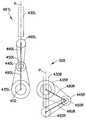
다른 실시예들에 따르면, 듀얼 동측 스카라 암들 및 기계적 스위치 메카니즘을 갖는 상기 기판 이송 장치는, 동축 구동 축 조립체에 의해 구동부로부터 동력을 제공받을 수 있다. 예를 들면, 도 4e에 도시된 바와 같이, 구동 시스템(100)은 모터들(104, 103)에 의해서 각각 구동되는 동축의 내부 및 외부 구동 축들(101, 102)을 가질 수 있다. 모터들(103, 104)은 각각 이들의 각 구동 축(102, 101)에 부착되는 로터(103R, 104R), 상기 로터들을 구동하기 위한 고정자(103S, 104S)를 가질 수 있으며, 고정자(103S, 104S)는 구동 시스템(100)의 하우징(100H)에 정적으로 연결된다. 다른 실시예들에서, 상기 구동 시스템은 동축이 아닐 수 있다. 구동 시스템(100)의 하우징(100H)은, 구송 시스템 하우징(100H)의 적어도 일부가 챔버 내벽의 일부를 형성하도록, 챔버(30; 도 4a 참조)에 결합될 수 있다. 일 실시예에서, 로터들(103R, 104R)은 챔버(30)의 대기 내에 배치되지만, 고정자들(103S, 104S)는 챔버 대기로부터 적절히 분리된다. 동축 구동부(100)의 적합한 예들은 미 국 특허 제5,720,590호, 제5,899,658호, 제5,813,823호 및 제6,485,250호 및/또는 미국 특허공개공보 제2003/0223853호에 개시된 것과 실질적으로 유사하며, 이들 문헌의 개시 사항은 참조에 의해 그 전체가 본 명세서에 포함되어 있다. 다른 실시예들에서, 예를 들면, 비동축 구동 조립체 또는 자성 구동 조립체와 같은 임의의 적합한 구동부가 이용될 수도 있다.According to other embodiments, the substrate transfer device having dual ipsilateral scalar arms and a mechanical switch mechanism may be powered from the drive by a coaxial drive shaft assembly. For example, as shown in FIG. 4E, thedrive system 100 may have coaxial inner andouter drive shafts 101, 102 driven bymotors 104, 103, respectively.Motors 103 and 104 may each haverotors 103R and 104R attached to theirrespective drive shafts 102 and 101,stators 103S and 104S for driving the rotors, andstator 103S, 104S is statically connected tohousing 100H ofdrive system 100. In other embodiments, the drive system may not be coaxial. Thehousing 100H of thedrive system 100 may be coupled to the chamber 30 (see FIG. 4A) such that at least a portion of the conveyingsystem housing 100H forms part of the chamber inner wall. In one embodiment, therotors 103R, 104R are disposed in the atmosphere of thechamber 30, but thestators 103S, 104S are properly separated from the chamber atmosphere. Suitable examples ofcoaxial drive 100 are substantially similar to those disclosed in US Pat. Nos. 5,720,590, 5,899,658, 5,813,823 and 6,485,250 and / or US Patent Publication No. 2003/0223853. The disclosure is incorporated herein in its entirety by reference. In other embodiments, any suitable drive may be used, such as, for example, a coaxial drive assembly or a magnetic drive assembly.

상기 구동부는 상기 구동부의 동적 부품들로부터 발생할 수 있는 파티클들로부터 기판이 오염되거나 손상되는 것을 방지하기 위하여 상기 기판 이송의 하우징 내에 수용될 수 있다. 본 실시예에서는, 전술한 바와 같이, 상기 동축 구동 조립체가 내부 및 외부 구동 축(101, 102)을 가질 수 있다. 외부 구동 축(102)은 상기 기판 이송의 하우징에 연결될 수 있으며, 이에 의해, 외부 구동 축(102)이 회전할 때, 상기 기판 이송 장치의 암들(491L, 491R)이 외부 구동 축(102) 의 회전 축 주위로 회전되도록 한다. 내부 구동 축(101)은 회전 지점(42)에서 상기 커플링 시스템에 연결될 수 있으며, 이에 의해, 내부 구동 축(101)이 회전할 때, 상기 커플링 시스템은 내부 구동 축(101)의 회전 축(즉, 회전 지점 42) 주위로 회전하거나 피봇될 것이다. 본 실시예에서, 외부 구동 축(102)은 상기 기판 이송 장치의 (일반적으로, 암 펼침/접힘을 위한 동력을 제공하는 T1 모터와 유사하게) 모토 로터에 연결될 수 있으며, 이에 의해, 상기 외부 구동 축이 회전될 때, 상기 이중 암들은 전술한 바와 같은 유사한 방법으로, 도 3-8에 도시된 바와 같이, 독립적으로 펼쳐지거나 접힐 수 있다. 실제로 구현되는 경우, 상기 동축 구동 조립체의 내부 구동 축(101은 상기 외부 구동 축과 동일한 방향으로 실질적으로 동일한 속도로 회전하 여, 상기 이송 장치의 암들이, 상기 기판 이송 장치의 암들이 실질적으로 일 단위로서 회전하는 동안 펼쳐지거나 접히는 것을 방지한다. 내부 구동 축(101)은 회전 지점(42에서 커플링 시스템을 통하여 (다소 모터 T2와 유사한) 허브 조립체에 연결되어, 내부 구동 축(101)이 회전할 대 상기 커플링 시스템이 상기 내부 구동 축의 회전 축(즉, 회전 지점(42) 주위로 회전하거나 피봇되도록 한다.The drive may be housed in the housing of the substrate transfer to prevent the substrate from being contaminated or damaged from particles that may arise from the dynamic components of the drive. In the present embodiment, as described above, the coaxial drive assembly may have internal andexternal drive shafts 101, 102. Theexternal drive shaft 102 can be connected to the housing of the substrate transfer, whereby when theexternal drive shaft 102 rotates, thearms 491L, 491R of the substrate transfer device are adapted to theexternal drive shaft 102. Allow it to rotate around the axis of rotation. Theinternal drive shaft 101 can be connected to the coupling system at therotation point 42, whereby when theinternal drive shaft 101 rotates, the coupling system rotates on theinternal drive shaft 101. (Ie rotation point 42) will be rotated or pivoted around. In this embodiment, theexternal drive shaft 102 can be connected to the moto rotor of the substrate transfer device (typically similar to a T1 motor that provides power for arm spreading / folding), whereby the external drive When the axis is rotated, the dual arms can be independently unfolded or folded, as shown in Figures 3-8, in a similar manner as described above. In practice, theinner drive shaft 101 of the coaxial drive assembly rotates at substantially the same speed in the same direction as the outer drive shaft, such that the arms of the transfer device are substantially the same as the arms of the substrate transfer device. Prevents unfolding or folding during rotation as a unit Theinternal drive shaft 101 is connected to the hub assembly (somewhat similar to motor T2) via a coupling system at therotation point 42 so that theinternal drive shaft 101 rotates. In some cases, the coupling system causes the inner drive shaft to rotate or pivot about an axis of rotation (ie, rotation point 42).

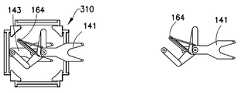
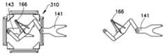
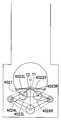
도 10a-10b를 참조하면, 동축 구동 조립체를 갖는 기계적 스위치 메카니즘을 포함하는 듀얼 동측 스카라 암들을 갖는 기판 이송 장치(310)이 도시되어 있다. 도 10a에서, 암들 A(141) 및 암들 B(143)을 포함하는 동축 구동 조립체를 갖는 상기 이송 장치가 이송 챔버(130) 내에 배치된다. 도 10b에서, 상기 이송 챔버(미도시)를 갖고 (명확성을 위하여 일부만 표시한) 암 A(141) 및 암 B 로서 듀얼 동측 스카라 암들이 도시되어 있다. 상기 암들 및 이송 챔버는 전술한 이송 채버(30) 내의 암들 A, B와 실질적으로 유사하다. 동일한 특징들은 동일한 참조 부호로 표시하였다. 이송을 위한 기판(310)은 도시하지 않았으나, 엔드 이펙터(132) 상에 배치될 것이다. 본 실시예에서, 엔드 이펙터(132)는 포크(forked) 형상을 가지고 있는 것으로 도시하였으나, 다른 실시예들에서, 상기 엔드 이펙터는 패들(pddle) 형상과 같은 형상을 포함할 수 있으며, 이에 한정되는 것은 아니다. 엔드 이펙터(132)는 리스트(wrist) 또는 피봇 조인트(134)에 피봇가능하게 연결되며, 차례로 각 암 A(141) 및 B(143)에 대하여 포어 암(136)에 연결된다. 포어 암(136)은 엘보우 또는 피봇 조인트(138)에 피봇가능하게 연결되며, 차례로 각 암 A(141) 및 암 B(143)에 대하여 어퍼 암(140)에 연결된다. 암 A(141) 및 암 B(143)을 위한 어퍼 암(140) 은 차례로 T1 및 T2 모터들(150, 144)를 위한 공통 베이스 또는 탑재 플레이트(142)에 각각의 암 쇼울더 조인트들(146)을 통하여 탑재된다. 상기 T1 및 T2 모터들을 위한 동축 구동 조립체의 중심은 또한 공통 베이스 또는 탑재 플레이트(142)의 중심이다. 본 실시예에서, 펼침 암(147)은 T1 모터(150)을 위한 동축 구동축으로부터 반지름 방향으로 바깥쪽으로 연장된다. 또한, 크랭크 링크(148)은 암 A(141) 및 암 B(143) 각각의 암 쇼울더 조인트들(146)을 펼침 암(147) 또는 모터 T1 상의 외선 조인트(152)에 연결한다. 도 10a-10b에 도시된 바와 같이, 본 실시예에서, 2 개의 크랭크 링크들(148)은 동축 구동 조립체(142)의 중심으로부터 오프셋된 공통 피봇 지점(152)을 공유하지만, 다른 실시예에서는, 상기 링크들이 오프셋된 외선 조인트들에서 모터 T1에 체결될 수도 있다.10A-10B, asubstrate transfer apparatus 310 with dual ipsilateral scara arms including a mechanical switch mechanism having a coaxial drive assembly is shown. In FIG. 10A, the transfer device having a coaxial drive assembly comprisingarms A 141 andarms B 143 is disposed withintransfer chamber 130. In FIG. 10B, dual ipsilateral scara arms are shown asarm A 141 and arm B (shown only partially for clarity) with the transfer chamber (not shown). The arms and the transfer chamber are substantially similar to the arms A and B in thetransfer channel 30 described above. Identical features are indicated by the same reference numerals. Thesubstrate 310 for the transfer is not shown, but will be disposed on theend effector 132. In the present embodiment, theend effector 132 is shown as having a forked shape, but in other embodiments, the end effector may include a shape such as a paddle shape, and the like. It is not. Theend effector 132 is pivotally connected to a wrist or pivot joint 134, which in turn is connected to theforearm 136 for eacharm A 141 andB 143. Thefore arm 136 is pivotally connected to the elbow or pivot joint 138, which in turn is connected to theupper arm 140 for eacharm A 141 andarm B 143.Upper arm 140 forarm A 141 andarm B 143 in turn has respectivearm shoulder joints 146 on a common base or mountingplate 142 for T1 andT2 motors 150, 144. It is mounted through. The center of the coaxial drive assembly for the T1 and T2 motors is also the center of the common base or mountingplate 142. In this embodiment, the spreadingarm 147 extends radially outward from the coaxial drive shaft for theT1 motor 150. The crank link 148 also connects thearm shoulder joints 146 of each of thearm A 141 and thearm B 143 to thespread arm 147 or the outer joint 152 on the motor T1. As shown in FIGS. 10A-10B, in this embodiment, the two cranklinks 148 share acommon pivot point 152 offset from the center of thecoaxial drive assembly 142, but in another embodiment, The links may be fastened to motor T1 at offset joints offset.

도 10a-10b를 참조하면, 엔드 이펙터(132) 상에 기판 S를 집거나 위치하기 위한 암 A(141) 또는 암 B(143)의 펼침을 작동시키기 위하여, T1 모터(150)은 회전하면서, T2 모터(144)는 고정된다. 상기 T1 모터가 일 방향으로 회전할 때, 제 1 암은 펼쳐지거나 접혀지고, 제 2 암은 도 3a-b를 참조하여 전술한 바와 같은 유사한 방식으로 움직이지는 않는다. 도 10a는 일 실시예에 따라 이송 챔버(130)의 영역(confine)을 지나는 펼침 위치에 있는 암 A(141)와 이송 챔버(130) 내에서 접혀질 수 있는 암 B를 도시한다. 암 A(141)의 이러한 움직임은 스토리지 챔버 또는 처리 스테이션 내에서 기판 S의 집기와 놓기를 가능하게 한다. 상기 암들의 순회전(pure rotation)을 달성하기 위하여, T2 모터(144 및 T1 모터(150)은 모두 동일한 각도로 회전한다. 이는 암 A(141)과 암 B 를 위한 크랭크 링크들(148)을 서로 에 대하여 고정시켜 펼침 또는 접힘을 달성하기 위한 상기 2 개의 암들 중 하나에 토크를 인가하지 않도록 한다. 동축 구동 조립체를 포함하는 본 실시예에서, T1 및 암 쇼울더 조인트들(146)은 회전 공통 축 주위로 회전한다.10A-10B, while operating the spreading ofarm A 141 orarm B 143 for picking up or placing substrate S onend effector 132,T1 motor 150 rotates, The T2 motor 144 is fixed. When the T1 motor rotates in one direction, the first arm is unfolded or folded and the second arm does not move in a similar manner as described above with reference to FIGS. 3A-B. FIG. 10A illustratesarm A 141 in an unfolded position past a confine oftransfer chamber 130 and arm B that may be folded withintransfer chamber 130 according to one embodiment. This movement ofarm A 141 enables the picking up and placing of the substrate S within the storage chamber or processing station. To achieve pure rotation of the arms, both the T2 motor 144 and theT1 motor 150 rotate at the same angle, which rotates the crank links 148 for thearm A 141 and the arm B from each other. So that no torque is applied to one of the two arms to achieve unfolding or folding, in this embodiment including a coaxial drive assembly, the T1 andarm shoulder joints 146 are around a common axis of rotation. Rotate to

도 11a-11d를 참조하면, 본 명세서에 개시된 동축 구동 조립체를 갖는 기계적 스위치 메카니즘을 포함하는 듀얼 동측 스카라 암들을 구비하는 기판 이송 장치에 있어서, 4 개의 펼침 위치에 있는 암 A(141)의 펼침 운동을 도시한다. 도 11a에서, 플레이트(144)를 T1 모터(150)에 탑재하는 상기 T2 모터 상의 암 쇼울더 조인트들(146)을 T1 모터(150)에 연결시키는 2 개의 크랭크 링크들(148) 및 펼침 암(147)은 T1(150)의 외주를 따라 지점 A(162)에서 수렴된다. 도 11b에서, T1(150)이 반 시계 방향으로 회전할 때, 크랭크 링크들(148) 및 펼침 암(147)은 T1의 외주를 따라 지점 B(164)까지 회전하며, 차례로 암 A 가 우측 방향(P 방향)으로 바깥쪽으로 펼쳐지게 하면서, 암 B(143)가 접힘 위치에서 실질적으로 고정되게 남아있게 한다. 도 11c에서, T1(150)이 시계 방향으로 더 회전할 때, 크랭크 링크들(148) 및 펼침 암(147)은 T1(150)의 외주를 따라 지점 C(166) 까지 더 회전하며, 차례로 암 A(141)이 우측 방향으로 바깥쪽으로 더 펼쳐지게 하면서 암 B(143)은 접힘 위치에서 실질적으로 고정되게 남아 있게 한다. 도 11d에서, T1(150) 이 시계 방향으로 더 회전할 때, 크랭크 링크들(148) 및 펼침 암(147)은 T1의 외주를 따라 지점 D(168)까지 더 회전하며, 차례로, 암 A(141) 가 우측을 향하여 바깥으로 더 펼쳐지게 하면서 암 B(143)이 접힘 위치에서 실질적으로 고정되게 남아있게 한다. 암 A(141)을 접기 위해, T1(150)의 방향은 지점들 C(166), B (164) 및 A(162)를 따 라 역전된다. 다른 실시예에서, 2 개의 암들(141, 143)을 위한 2 개의 크랭크 링크들(148)은 T1(150)에 대한 펼침 암(147)의 동일 지점 상으로 수렴될 필요는 없다.11A-11D, in a substrate transfer device having dual ipsilateral scara arms comprising a mechanical switch mechanism having a coaxial drive assembly as disclosed herein, the unfolding movement ofarm A 141 in four unfolded positions. To show. In FIG. 11A, the two cranklinks 148 and the spreadingarm 147 that connect thearm shoulder joints 146 on the T2 motor to theT1 motor 150 that mount the plate 144 to the T1 motor 150. ) Converges at point A 162 along the perimeter ofT1 150. In FIG. 11B, whenT1 150 rotates counterclockwise, cranklinks 148 and spreadingarm 147 rotate to pointB 164 along the perimeter of T1, in turn arm A being in the right direction.Arm B 143 remains substantially fixed in the folded position, unfolding outward (in the P direction). In FIG. 11C, whenT1 150 rotates further clockwise, cranklinks 148 and spreadingarm 147 rotate further topoint C 166 along the perimeter ofT1 150, in turn the arm.Arm B 143 remains substantially fixed in the folded position while allowing A 141 to extend further outward in the right direction. In FIG. 11D, whenT1 150 rotates further clockwise, cranklinks 148 and spreadingarm 147 further rotate to pointD 168 along the perimeter of T1, in turn, arm A (Arm 143 remains substantially fixed in the folded position, with 141 further extended outward to the right. To foldarm A 141, the direction ofT1 150 is reversed alongpoints C 166,B 164 andA 162. In another embodiment, the two cranklinks 148 for the twoarms 141, 143 need not converge on the same point of the unfoldingarm 147 for theT1 150.

본 명세서에 개시된 기판 이송 장치의 다른 실시예에 따르면, 도 3-11에 개시된 듀얼 동측 스카라 암 구동 장치 대신에, 도 12a-12b 및 13a-13c에 도시된 바오 같은 정방형(bisymmetric) 스카라 암 구동 장치가 이용될 수 있다. 정방형 스카라 암 구동 장치에서, 기판 이송 장치의 2 개 이상의 암들은 서로에 대하여 다른 또는 반대 방향으로 배치되고/또는 배향될 수 있다. 전술한 바와 유사한 기계적 스위치 메카니즘을 이용하는 정방형 스카라 암 구성을 갖는 기판 이송 장치는 암 A 및 암 B가 동일 평면 내에 위치하게 하고 그에 따라 더 작은 동작 범위(envelop of motion)을 갖도록 한다. 차례로, 이에 의해, 이송 챔버의 부피가 최소화될 수 있으며, 차례로, 기판의 교차 오염 가능성을 감소시킨다. 듀얼 동측 암들에 관하여 전술한 바와 마찬가지로, 기계적 스위치 메카니즘을 이용하는 정방형 암 구성을 갖고서, 암 A 및 암 B의 독립적인 펼침/접힘 및 회전이 겨우 2 개의 모터들 (T1 및 T2)로 달성될 수 있다. 상기 T1 및 T2 모터들은 다시 상기 이송 챔버들의 (가능한 한 진공에 대한 외부의) 벽들에 일체화된 스테이터 권선들에 결합된 2 개의 적층된 링들(로터들)로 구성될 수 있으며, 이에 의해, 이송 챔버의 바닥에 진공 시스템 부품들을 탑재하는 것이 가능해진다. 또한, 어퍼 암을 이송 챔버의 중심으로부터 어긋나게 배치시킴으로써, 종래의 스카라 암 구성과 비교시 현저히 더 작은 암들로 SEMI 달성을 가능하게 한다.According to another embodiment of the substrate transfer apparatus disclosed herein, instead of the dual ipsilateral scara arm driving apparatus disclosed in FIGS. 3-11, a bisymmetric scara arm driving apparatus such as Bao shown in FIGS. 12A-12B and 13A-13C Can be used. In a square scara arm drive device, two or more arms of the substrate transfer device can be arranged and / or oriented in different or opposite directions with respect to each other. A substrate transfer device having a square scara arm configuration using a mechanical switch mechanism similar to that described above allows the arms A and B to be positioned in the same plane and thus have a smaller envelope of motion. In turn, the volume of the transfer chamber can thereby be minimized, which in turn reduces the possibility of cross contamination of the substrate. As described above with respect to dual ipsilateral arms, with a square arm configuration using a mechanical switch mechanism, independent spreading / folding and rotation of arm A and arm B can be achieved with only two motors T1 and T2. . The T1 and T2 motors may in turn be composed of two stacked rings (rotors) coupled to stator windings integrated into the walls of the transfer chambers (as far as possible outside of the vacuum), whereby the transfer chamber It becomes possible to mount the vacuum system components at the bottom of the. In addition, by displacing the upper arm from the center of the transfer chamber, SEMI can be achieved with significantly smaller arms compared to conventional Scara arm configurations.

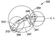
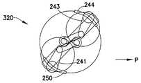
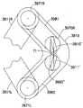
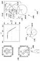
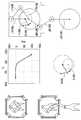
도 12a-12b를 참조하면, 목적에 따라 실질적으로 독립적인 암 운동을 위한 정방형 스카라 암 구성 및 기계적 스위치 메카니즘으로서 지칭될 수 있는 것을 구비하는 이송 장치(320)의 대략적인 평면도 및 모터의 이동에 따른 각 암 동작을 도시하는 그래프가 각각 도시된다. 기계적 스위치 메카니즘은 대체로 전술한 것과 유사하며, 대응되는 암부들(예를 들면, 스카라 암들의 어퍼 암들) 상의 외선 조인트들에 의해 각각 연결되는 2 개 이상의 링크들(247, 248)을 포함할 수 있다. 본 실시예에서, T1 모터(250) 및 T2 모터(244) 와 같은 각 모터는 이들에 피봇가능하게 연결된 링크(247, 248)을 갖는다(예를 들면, T1 모터에는 링크(248) 및 T2 및 T2 모터에는 링크(247)임). 도시된 실시예에서, 하나의 크랭크 링크(247)는 암 B(241)의 엘보우 조인트(238)를 T2(244)에 연결한다. 다른 크랭크 링크(248)은 암 A(244)의 엘보우 조인트(238)를 T1(250)에 연결한다. T1 및 T2(250, 244) 는 도 4d에 도시된 것과 실질적으로 유사한 모터들일 수 있다. 본 실시예에서, 각 스카라 암은 예를 들면 상기 T1, T2 모터들의 각 로터의 쇼울더 조인트에서 해당 외선 조인트(246A, 246B)에 의해 체결된다. 도 12a에 잘 도시된 바와 같이, 본 실시예에서, (암 A의) 외선 조인트(246A)는 상기 T2 모터 로터에 고정되고, (암 A의) 어퍼 암(240A)에 일단부가 체결되는 링크(248)는 상기 T1 모터 로터에 체결된다. 역으로, 암 B의 쇼울더 조인트(246B)가 상기 T1 모터 로터에 고정되고, 링크(247) 가 상기 T2 모터 로터에 핀 고정된다.12A-12B, a schematic plan view of atransfer device 320 having a what is referred to as a square scara arm configuration and a mechanical switch mechanism for substantially independent arm movement, depending on the purpose and movement of the motor. A graph showing each arm operation is shown respectively. The mechanical switch mechanism is generally similar to that described above and may include two ormore links 247 and 248 each connected by external joints on corresponding arm portions (eg, upper arms of the scara arms). . In this embodiment, each motor, such asT1 motor 250 andT2 motor 244, haslinks 247 and 248 pivotally connected thereto (e.g., T1 motor includeslinks 248 and T2 and T2 motors are links 247). In the illustrated embodiment, one cranklink 247 connectselbow joint 238 ofarm B 241 toT2 244. Another cranklink 248 connectselbow joint 238 ofarm A 244 toT1 250. T1 andT2 250, 244 may be motors substantially similar to those shown in FIG. 4D. In this embodiment, each scara arm is fastened by correspondingouter joints 246A and 246B at shoulder joints of the respective rotors of the T1 and T2 motors, for example. As best shown in Fig. 12A, in the present embodiment, the outer joint 246A (of arm A) is fixed to the T2 motor rotor, and the link of which one end is fastened to theupper arm 240A (of arm A) ( 248 is fastened to the T1 motor rotor. Conversely, shoulder joint 246B of arm B is fixed to the T1 motor rotor and link 247 is pinned to the T2 motor rotor.

도 12a에 도시된 실시예에서는, 이송 챔버(미도시)를 갖는 암 A(241) 및 암 B(243)으로서 정방형 스카라 암들이 도시되어 있다. 이송(320)의 기판은 S로 지시 되어 있으며, 엔드 이펙터(232) 상에 배치된다. 상기 엔드 이펙터는 임의의 적합한 포크(fork) 및 패들(paddle) 형을 포함하는 임의의 형태를 가질 수 있지만, 이에 제한되는 것은 아니다. 엔드 이펙터(232 A, B)는 리스트 조인트(234 A, B)에 피봇가능하게 연결되고, 차례로, 각 암 A(241) 및 B(243)을 위한 포어 암(236 A, B)에 연결된다. 포어 암(236)은 엘보우 조인트(238)에 피봇가능하게 연결되고, 차례로, 암 A(241) 및 암 B(243)의 각각에 대하여 어퍼 암(240)에 연결된다. 전술한 바와 같이, 암 A(241) 및 B(243) 을 위한 어퍼 암(들)(240 A, B)는 차례로 각각의 암 쇼울더 조인트(들)(246 A, B)에 의해 상기 T1, T2 모터(들)을 위한 해당 로터(들)(244, 250)에 각각 탑재된다. 전술한 바와 같이, 하나의 크랭크 링크(247)은 암 B(243의 엘보우 조인트(238)를 T2(244에 연결한다. 다른 크랭크 링크(248) 는 암 A (241)의 엘보우 조인트(238)를 T1(250)에 연결시킨다.In the embodiment shown in FIG. 12A, square scara arms are shown asarm A 241 andarm B 243 with a transfer chamber (not shown). The substrate oftransfer 320 is indicated by S and is disposed onend effector 232. The end effector may have any form, including but not limited to any suitable fork and paddle type. End effectors 232 A and B are pivotally connected towrist joints 234 A and B, which in turn are connected tofore arms 236 A and B for respective arms A 241 andB 243. . Thefore arm 236 is pivotally connected to the elbow joint 238, which in turn is connected to the upper arm 240 for each of thearm A 241 and thearm B 243. As mentioned above, the upper arm (s) 240 A, B for arms A 241 andB 243 are in turn made by the respective arm shoulder joint (s) 246 A, B to the T1, T2. Mounted on corresponding rotor (s) 244 and 250 for the motor (s), respectively. As described above, one cranklink 247 connectselbow joint 238 ofarm B 243 toT2 244. The other crank link 248 connectselbow joint 238 ofarm A 241. ToT1 250.

엔드 이펙터(232) 상에 기판 (S)를 집기 및 놓기 위한 암 A(241) 또는 암 B(243 의 펼침을 달성하기 위하여, T1 모터(250)은 회전하면서 T2 모터(244)는 고정된다. 이런 종류의 스위치 타입 메카니즘을 이용하여, 일 예로서, T1(250)이 일 방향으로 회전하고, T2(244)가 정적일 때, 이것은 하나의 암의 펼침 및 접힘을 달성한다. 더욱 상세하게는, T1 또는 T2 모터들 중 어느 하나가 회전하여 T2 와 T1 모터들 사이에 일 방향으로 상대적인 이동을 초래하면, 제 1 암은 펼쳐지거나 접혀지지면서, 제 2 암은 실질적으로 기계적 스위치 메카니즘 때문에 실질적으로 움직이지 않는다. T2(244) 와 T1(250) 모터의 상대적인 움직임이 반대 방향인 경우, 이것은 제 1 암에 대해 반대쪽에 위치하는 다른 암의 펼침을 기동시킨다. 더욱 상 세하게는, 제 2 모터가 반대 방향으로 회전할 때, 제 2 암은 펼쳐지거나 접혀지면서, 제 1 암은 실질적으로 기계적 스위치 메카니즘의 동작 원리 때문에 움직이지 않는다. 도시된 실시예에서, 오직 예시적인 목적으로, 대응하는 로터들(250, 244) 상의 각 외선 조인트들(예를 들면, 쇼울더 조인트(246) A, B 및 링크 피봇들)은 실질적으로 동축인 것으로 도시되어 있으며, 다른 실시예에서, 각 로터 상의 쇼율더 조인트 및 링크 피봇들은 서로로부터 오프셋될 수 있다. 실질적으로 일 단위로서 암들(241, 243)의 회전을 기동시키기 위해, T2 모터(244) 및 T1 모터(250)은 모두 동일한 각도까지 회전한다.TheT2 motor 244 is fixed while rotating theT1 motor 250 to achieve the unfolding of thearm A 241 or thearm B 243 for picking and placing the substrate S on theend effector 232. [ Using this type of switch type mechanism, as an example, whenT1 250 rotates in one direction andT2 244 is static, this achieves the unfolding and folding of one arm. If either one of the T1 or T2 motors rotates to cause a relative movement in one direction between the T2 and T1 motors, the first arm is unfolded or folded, while the second arm is substantially due to the mechanical switch mechanism. If the relative movement of theT2 244 andT1 250 motors is in the opposite direction, this triggers the unfolding of the other arm located opposite to the first arm. Rotates in the opposite direction, the second Is unfolded or folded, the first arm does not move substantially due to the operating principle of the mechanical switch mechanism In the illustrated embodiment, for illustrative purposes only, the respective outer joints on the correspondingrotors 250, 244 ( For example,shoulder joint 246 A, B and link pivots) are shown to be substantially coaxial, and in other embodiments, the shoulder joint and link pivots on each rotor may be offset from each other. In order to activate the rotation of thearms 241 and 243 as a unit, both theT2 motor 244 and theT1 motor 250 rotate to the same angle.

도 12b를 참조하면, 기계적 스위치 메카니즘의 동작 원리가 T1 과 T2 사이의 회전 앵글의 차이에 대한 암들 A 및 B의 펼침 각을 도시하는 그래프로 나타내었다. 암 펼침 각과 펼쳐지거나/접혀지는 암에 대한 T1과 T2 사이의 차이 사이에는 선형 관계를 갖는다. 하나의 암이 펼쳐지거나/접혀지면서, 다른 암은 실질적으로 펼쳐지거나/접혀지지 않는다. 듀얼 정방형 스카라 암들을 사용하는 기계적 스위치 메카니즘에 있어서, 2 개의 크랭크 링크들(247, 248)은 대칭 축에 반대로 부착되어, T1이 반대 방향으로 회전하면, 하나의 암은 물리적으로 잠기고, 다른 암은 T1에 의해 자유롭게 회전한다. 마찬가지로, T1이 반대 방향으로 회전하면, 이전에 잠겨있던 암은 해제되고 자유롭게 T1에 의해 회전하면서, 이전의 자유로운 암은 물리적으로 잠겨진다. 이에 의하면, T1 회전의 방향과 각도에 따라 2 개의 암들의 독립적인 펼침이 가능해진다. 또한, T1 및 T2가 모두 같이 회전하면, 2 개의 암들은 펼쳐지지 않도록 회전한다.Referring to FIG. 12B, the operating principle of the mechanical switch mechanism is shown graphically showing the spread angles of arms A and B against the difference in rotation angle between T1 and T2. There is a linear relationship between the angle of arm spread and the difference between T1 and T2 for the arm being stretched / folded. As one arm unfolds / folds, the other arm does not substantially unfold / fold. In a mechanical switch mechanism using dual square scara arms, the two cranklinks 247, 248 are attached opposite to the axis of symmetry so that when T1 rotates in the opposite direction, one arm is physically locked and the other arm is Rotate freely by T1. Likewise, when T1 rotates in the opposite direction, the previously locked arm is released and freely rotated by T1, while the former free arm is physically locked. According to this, two arms can be unfolded independently according to the direction and angle of T1 rotation. Also, if both T1 and T2 rotate together, the two arms rotate so as not to unfold.

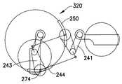
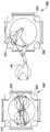
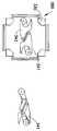
도 13a-13c를 참조하면, 도 12a-12b에 도시된 기계적 스위치 메카니즘을 포함하는 듀얼 정방형 스카라 암들을 갖는 기판 이송 장치(320)이 도시되어 있다. 도 13a 및 13c 에서, 암들 A 및 B를 포함하는 이송 장치가 이송 챔버(230) 내에 배치된다. 도 13b에서, 듀얼 정방형 스카라 암들은 이송 챔버(미도시)와 함께 암 A(241) 및 암 B(243)으로서 나타내었다.Referring to FIGS. 13A-13C, asubstrate transfer apparatus 320 with dual square scara arms including the mechanical switch mechanism shown in FIGS. 12A-12B is shown. In FIGS. 13A and 13C, a transfer device comprising arms A and B is disposed intransfer chamber 230. In FIG. 13B, dual square scara arms are shown asarm A 241 andarm B 243 with a transfer chamber (not shown).

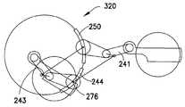
도 14a-14c를 참조하면, 본 명세서에 개시된 기P적 스위치 메카니즘을 포함하는 듀얼 정방형 스카라 암들을 갖는 기판 이송 장치(320)를 위한 3 개의 서로 다른 펼침 위치에 있는 암 B(243)의 펼침 운동이 도시되어 있다. 도 14a에서, 암 B(243)은 약간 펼쳐진 것으로 도시되어 있고, 암 A(241)은 T1(250)을 따라 지점 A(262에서 암 B(243) 의 운동을 기동시키는 크랭크 링크(248)과 함께 완전히 접혀진 것으로 도시되어 있다. 도 14b에 도시된 바와 같이, T1(250)이 T2 모터 로터(244)에 상대적으로) 시계 방향으로 회전하면서, T1 로터(250)에 연결된 크랭크 링크(248)은 T1(250)과 함께 더 움직이며, 차례로, 암 B(243)이 우측 방향으로 바깥 쪽으로 더 펼쳐지게 하면서 암 A(241)은 여전히 접힌 위치에서 실질적으로 고정된 채로 있게 된다(그러나, 로터(250)의 회전과 함께 회전할 수도 있다). 그에 따라, 암 A(241)의 움직임을 기동시키기 위한) 크랭크 링크(247)가 외선 조인트(240 A에서 해제되어, 쇼울더 조인트(246A) 주위로 어퍼 암(240A)에 대하여 어떠한 회전 운동도 초래하지 않는다. 도 14c에 도시된 바와 같이, T1(250)이 시계 방향으로 더 회전하면서, T1 로터(250)에 연결된 크랭크 링크(248)는 T1(250)을 따라 더 움직이고, 이에 의해, 차례로, 암 B(243)이 우측 방향으로 바깥 쪽으로 더 펼쳐지면 서, 암 A(241) 이 여전히 접힌 위치에서 실질적으로 고정된 채로 남게 된다. 그에 따라, 암 B(243)의 움직임을 기동시키기 위한 크랭크 링크(248)가 T1 모터를 따라 지점 B(264)로부터 지점 C(266)으로 더 움직인다. 암 B(243) 을 접기 위하여, T1(250) 의 방향은 지점들 C(266), B(264) 및 A(262)를 따라 역전된다. Referring to FIGS. 14A-14C, the unfolding motion ofarm B 243 in three different unfolded positions forsubstrate transfer device 320 with dual square scara arms including the mechanical switch mechanism disclosed herein. Is shown. In FIG. 14A,arm B 243 is shown as being slightly unfolded,arm A 241 with crank link 248 that initiates movement ofarm B 243 at point A 262 alongT1 250. Shown fully folded together, as shown in Fig. 14B, while theT1 250 rotates clockwise (relative to the T2 motor rotor 244), the crank link 248 connected to theT1 rotor 250 Moving further withT1 250, in turn,arm A 241 remains substantially fixed in the folded position whilearm B 243 extends further outward in the right direction (however,rotor 250 It may rotate with the rotation of). Accordingly, the crank link 247 (to activate the movement of the arm A 241) is released at the outer joint 240 A, causing no rotational movement with respect to theupper arm 240A around the shoulder joint 246A. As shown in Fig. 14C, as theT1 250 rotates further clockwise, the crank link 248 coupled to theT1 rotor 250 moves further along theT1 250, thereby, in turn, the arm. AsB 243 is further extended outwards in the right direction,arm A 241 remains substantially fixed in the folded position, thus providing a crank link for activating the movement of arm B 243 ( 248 further moves along point T1 motor frompoint B 264 topoint C 266. To foldarm B 243, the direction ofT1 250 is directed topoints C 266,B 264 and Reversed along A 262.

도 15a-15c를 참조하면, 본 명세서에 개시된 기계적 스위치 메카니즘을 포함하는 듀얼 정방형 스카라 암들을 갖는 기판 이송 장치(320)의 기판 이송 장치에 대한 3 가지 다른 펼침 위치들에 있는 암 A(241)의 펼침 운동이 도시되어 있다. 실제로, 도 15a-15c에 도시된 이송 장치는 (예를 들면, 기판 홀딩 스테이션으로부터 스왑(swap)을 기동시길 때와 같이) 도 14a-14c에 도시된 장치의 배향으로부터 180 도 회전될 수 있다. 도 15a에서, 암 A(241)은 약간 펼쳐진 것으로 도시되어 있지만, T1(250) 을 따라 지점 C(272)에서 크랭크 링크(247)이 암 A(241)의 운동을 기동시키고 있고, 암 B(243) 은 완전히 접혀진 것으로 도시되어 있다. 도 15b에 도시된 바와 같이, T2 로터(244)가 T1 로터(250)에 대하여 상대적으로 반시계 방향으로 회전하면, T2 로터(244)에 연결된 크랭크 링크(247)도 T2 로터(244)의 외주를 따라 움직이며, 이에 의해, 이번에는, 암 A(241)이 우측 방향으로 바깥쪽으로 펼쳐지면서, 암 B(243은 접힌 위치에서 실질적으로 고정된 채로 남게 된다(크랭크 링크(248)은 해제됨). 그에 따라, 암 A(241)의 움직임을 기동시키는 크랭크 링크(247은 T2(244)를 따라 지점 D(272)로부터 지점 E(274)까지 움직인다. 도 15c에 도시된 바와 같이, T2(244)가 반시계 방향으로 더 회전하면서, T2 로터(244)에 연결된 크랭크 링크(247은 T2(244)의 외주를 따라 더 회전하며, 이에 의해, 이번에 는, 암 A(241)이 우측 방향으로 바깥쪽으로 더 연장되지만, 암 B(243)은 여전히 접힌 위치에서 실질적으로 고정된 채로 남게 된다. 그에 따라, 암 A(241)을 기동시키는 크랭크 링크(247)은 T2(244)를 따라 지점 E(247)로부터 지점 F(246)으로 움직인다. 암 A(241)을 접기위하여, T2(244)의 방향은 지점들 F(276), E(274) 및 D(272)를 따라 역전된다.15A-15C, thearm A 241 in three different unfolded positions for the substrate transfer device of thesubstrate transfer device 320 having dual square scara arms including the mechanical switch mechanism disclosed herein. The unfolding movement is shown. In practice, the transfer device shown in FIGS. 15A-15C can be rotated 180 degrees from the orientation of the device shown in FIGS. 14A-14C (eg, when initiating a swap from a substrate holding station). In FIG. 15A,arm A 241 is shown as slightly unfolded, but cranklink 247 is activating movement ofarm A 241 atpoint C 272 alongT1 250, and arm B ( 243 is shown fully folded. As shown in FIG. 15B, when theT2 rotor 244 rotates in a counterclockwise direction relative to theT1 rotor 250, the crank link 247 connected to theT2 rotor 244 also has an outer circumference of theT2 rotor 244. , Thereby thistime arm A 241 unfolds outward to the right, leavingarm B 243 substantially fixed in the folded position (cranklink 248 is released). Accordingly, the crank link 247 that activates the movement of thearm A 241 moves along theT2 244 from thepoint D 272 to thepoint E 274. As shown in FIG. 15C, theT2 244. Further rotates counterclockwise, the crank link 247 connected to theT2 rotor 244 further rotates along the outer periphery of theT2 244, whereby thearm A 241 is outwards in the right direction. Extending further to the left,arm B 243 remains substantially fixed in the folded position. D. The crank link 247 for activatingarm A 241 moves frompoint E 247 to point F 246 alongT2 244. To foldarm A 241, The direction is reversed alongpoints F 276,E 274 andD 272.

도 16a-16d를 참조하면, 본 명세서에 개시된 기계적 스위치 메카니즘을 포함하는 듀얼 정방형 스카라 암들을 갖는 기판 이송 장치(320)에 대한 4 가지 다른 회전 위치에 있는 암 A(241) 및 암 B(243)의 회전 운동이 도시되어 있다. 도 16a에서, 2 개의 암들(241, 243)은 P 를 따라 반대 방향을 가리키고 있다. T1 및 T2 모터들(250, 244)이 모두 동일한 방향(예를 들면, 반시계 방향)으로 동일한 양만큼 회전하면, 암들 A 및 B(241, 243)은, 이에 따라, T1 및 T2가 회전하는 방향에 따라) 예를 들면, 도 16b, 16c 및 16d에서 나타낸 컨티넘을 따라 반시계 방향으로 회전할 것이다. T1 및 T2가 시계 방향으로 동일한 양만큼 회전하는 다른 실시예에서, 암들 A 및 B(241, 243) 은 이에 대응하여, 예를 들면, 도 16b, 16c 및 16d에 도시된 반시계 방향의 회전과 실질적으로 반대인 시계 방향으로 회전할 것이다(즉, 회전의 순서가 16a 내지 16d가 아닌 16d로부터 16a가 됨)16A-16D,arm A 241 andarm B 243 in four different rotational positions relative tosubstrate transfer device 320 with dual square scara arms including the mechanical switch mechanism disclosed herein. The rotational motion of is shown. In FIG. 16A, the twoarms 241, 243 are pointing in the opposite direction along P. If the T1 andT2 motors 250, 244 both rotate by the same amount in the same direction (eg counterclockwise), the arms A andB 241, 243 will thus rotate in which T1 and T2 rotate. Direction, for example, it will rotate counterclockwise along the continents shown in FIGS. 16B, 16C and 16D. In another embodiment in which T1 and T2 rotate clockwise by the same amount, arms A andB 241, 243 correspond correspondingly to, for example, the counterclockwise rotation shown in FIGS. 16B, 16C and 16D. Will rotate in a substantially opposite clockwise direction (i.e. the order of rotation will be from 16d to 16a rather than 16a to 16d)

본 명세서에 개시된 기계적 스위치 메카니즘을 이용한 듀얼 정방형 스카라 암들을 갖는 기판 이송 장치의 다른 실시예에서, 동축 구동 축 조립체가 T1 및 T2 모터를 스카라 암들 및 기계적 스위치에 결합시기키 위하여 사용될 수 있다. 본 실시예에서, T1 및 T2 의 회전 중심은 실질적으로 동일할 수 있다. 동축 구동은 실질적으로 도 4e를 참조하여 상술한 것과 실질적으로 유사한다. 외부 구동 축 102 는 기판 이송 장치의 T1 모터 로터에 연결되어, 외부 구동 축(102)가 회전할 때, 듀얼 암들은 도 12-16에서 상술한 기계적 스위치의 동작 원리에 따라 독립적으로 펼쳐지거나/접힐 수 있다. 실제로, 상기 동축 구동의 내부 구동 축 101은 상기 이송 장치의 암들이 상기 기판 이송 장치의 암들이 회전하면서 펼쳐지거나 접혀지는 것을 방지하기 위하여 동일한 방향, 동일한 속도로 회전할 것이다. 내부 구동 축 101은 회전 지점(242 에서 커플링 시스템을 통하여 T2 허브 조립체에 연결되어, 내부 구동 축 101이 회전할 때, 커플링 시스템이 내부 구동 축 101의 회전축(즉, 회전 지점; 242) 주위로 회전하거나 피복하여 T2의 회전을 기동시킨다.In another embodiment of a substrate transfer device having dual square scara arms using the mechanical switch mechanism disclosed herein, a coaxial drive shaft assembly can be used to couple the T1 and T2 motors to the scara arms and the mechanical switch. In this embodiment, the centers of rotation of T1 and T2 may be substantially the same. Coaxial drive is substantially similar to that described above with reference to FIG. 4E. Theexternal drive shaft 102 is connected to the T1 motor rotor of the substrate transfer device so that when theexternal drive shaft 102 rotates, the dual arms are independently unfolded / folded in accordance with the operating principle of the mechanical switch described above in FIGS. 12-16. Can be. In practice, theinner drive shaft 101 of the coaxial drive will rotate at the same direction, at the same speed, to prevent the arms of the transfer device from unfolding or folding as the arms of the substrate transfer device rotate. Theinternal drive shaft 101 is connected to the T2 hub assembly via a coupling system at rotation point 242 such that when theinternal drive shaft 101 rotates, the coupling system is about the rotation axis (ie, rotation point 242) of theinternal drive shaft 101. Rotate or cover to activate the rotation of T2.

도 17a-17b를 참조하면, 동축 구동 조립체를 갖는 기계적 스위치 메카니즘을 포함하는 듀얼 정방형 스카라 암들을 갖는 기판 이송 장치가 개시된다. 도 17a-17b에서, 암 A(341) 및 암 B(343)을 포함하는 동축 구동 조립체를 갖는 이송 장치(380)는 이송 챔버(330) 내에 배치된다. 본 실시예에서 상기 동축 구동 조립체는 도 3a 및 도 4a-4d 를 참조하여 전술한 챔버(330)의 벽들 내부로 일체화된 고정자들을 포함할 수 있다. 다른 실시예들에서 상기 동축 구동은 도 4e에 도시된 것과 유사할 수 있다. 도 17c에서 상기 듀얼 정방형 스카라 암들은 상기 이송 챔버(미도시)의 암 A(341) 및 암 B(미도시)로서 도시되어 있다. 이송을 위한 기판 S는 도 17a의 포크형 엔드 이펙터(332)상에 놓여진 것으로 도시되어 있지만, 도 17b-17c에는 도시하지 않았다. 엔드 이펙터(332)는 패들형을 포함하는 다른 형상을 가질 수 있지만, 이에 제한되는 것은 아니다. 엔드 이펙터(332)는 리스트 또는 피봇 조인트(334)에 피봇 가능하게 연결되며, 이에 의해 차례로 암 A(341) 및 암 B(343)의 각각을 위한 포어 암(336)에 연결된다. 포어 암(336)은 엘보우 또는 피봇 조인트(338)에 피봇 가능하게 연결되며, 이에 의해 차례로 암 A(341) 및 암 B(343)의 각각을 위한 어퍼 암(340)에 연결된다. 암 A(341) 및 암 B(343)을 위한 어퍼 암(340)은 차례로 이들의 각각의 암 쇼울더 조인트들(346)에 의해 T1 및 T2 모터들(350, 344)을 위한 공통 베이스 또는 마운틴 플레이트(342)에 탑재된다. T1 및 T2 모터들을 위한 동축 구동 조립체의 중심은 또한 공통 베이스 또는 마운틴 플레이트(342)의 중심일 수 있다. 본 실시예에서 2 개의 펼침 암들(349a, 349b)은 T1 및 T2 모터들(350, 444)을 위한 동축 구동축으로부터 반지름 방향으로 바깥쪽으로 펼쳐진다. 또한, 2 개의 크랭크 링크들(347, 348)은 암 A(341) 및 암 B(343)의 각각을 위한 암 쇼율더 조인트들(346)을 펼침 암들(349a, 349b)상의 피봇 지점(352, 도 17c의 점선으로 표시됨)에 연결한다. 펼침 암들(349a, 349b)은 암 쇼울더(346)을 T1(350) 및 T2(444)의 회전 축(351)의 중심에 연결한다. 도 17b-17c에 도시된 바와 같이, 2 개의 펼침 암들은 다른 축으로부터 나왔지만, 동일한 회전축(351)을 갖는다. 2 개의 크랭크 링크들(347, 348)은 공통 수렴점 또는 피봇 지점들을 공유하지 않으며, 동축 구동 조립체(351)의 중심으로부터 오프셋된다.Referring to FIGS. 17A-17B, a substrate transfer apparatus with dual square scara arms including a mechanical switch mechanism having a coaxial drive assembly is disclosed. 17A-17B, atransfer device 380 having a coaxial drive assembly includingarm A 341 andarm B 343 is disposed withintransfer chamber 330. In this embodiment, the coaxial drive assembly may include stators integrated into the walls of thechamber 330 described above with reference to FIGS. 3A and 4A-4D. In other embodiments the coaxial drive can be similar to that shown in FIG. 4E. In FIG. 17C the dual square scara arms are shown asarm A 341 and arm B (not shown) of the transfer chamber (not shown). The substrate S for transfer is shown lying on thefork end effector 332 of FIG. 17A, but is not shown in FIGS. 17B-17C.End effector 332 may have other shapes, including, but not limited to, paddle type.End effector 332 is pivotally connected to wrist or pivot joint 334, which in turn is connected to porearm 336 for each ofarm A 341 andarm B 343. Thefore arm 336 is pivotally connected to an elbow or pivot joint 338, thereby in turn to anupper arm 340 for each ofarm A 341 andarm B 343.Upper arm 340 forarm A 341 andarm B 343 is in turn a common base or mountain plate for T1 andT2 motors 350, 344 by their respectivearm shoulder joints 346. 342 is mounted. The center of the coaxial drive assembly for the T1 and T2 motors may also be the center of the common base ormountain plate 342. In this embodiment the two unfoldingarms 349a and 349b extend radially outward from the coaxial drive shaft for the T1 andT2 motors 350 and 444. In addition, the two cranklinks 347 and 348 extend the arm show rater joints 346 for each ofarm A 341 andarm B 343 andpivot point 352 onarms 349a and 349b. (Indicated by the dotted line in Fig. 17C). Thespread arms 349a and 349b connect thearm shoulder 346 to the center of therotation axis 351 ofT1 350 andT2 444. As shown in FIGS. 17B-17C, the two spread arms come from different axes but have the same axis ofrotation 351. The two cranklinks 347, 348 do not share a common convergence point or pivot points and are offset from the center of thecoaxial drive assembly 351.

도 17-17c를 참조하면, 엔드 이펙터(332) 상에 기판 S를 집기 및 놓기를 위하여 암 A(341) 및 암 B(343)의 펼침을 기동시키기 위하여, T1 모터(350)은 회전하면서, T2 모터(344)는 정적으로 있는다. T1 모터가 일 방향으로 회전하면, 제 1 암은 펼쳐지거나 접혀지지만, 제 2 암은 도 12a-12b를 참조하여 전술한 바와 같은 동작 원리에 따라 실질적으로 움직이지 않는다. 특히, 암 A(341)을 펼치기 위하여, T1(350)은 반시계 방향으로 회전하고, 이에 의해, 크랭크 링크(348)이 암 A(341)의 어퍼 암(340)을 반시계 방향으로 회전시키고, 이에 의해, 이번에는, 암 A(341)이 펼쳐지게 된다. 도 17b는 이송 챔버(330)의 영역을 벗어난 펼침 위치에 있는 암 A(341)과 이송 챔버(330) 내에 접혀 있는 암 B(343)을 도시한다. 암 A(341)의 이러한 운동은 기판 S가 스토리지 챔버 또는 처리 스테이션 내에서 픽업되거나 재치되는 것을 가능하게 한다. 실질적으로 일 단위로서 상기 암들의 회전을 기동시키기 위하여, T2 모터(344) 및 T1 모터(350)은 모두 동일한 방향으로 동일한 각도로 회전한다. 이에 의해, 암 A(341) 및 암 B(343)을 위한 크랭크 링크들(347, 348) 및 펼침 암들(349a, b)가 서로에 대하여 고정되어, 2 개의 암들 중 어느 하나에 펼침 또는 접힘을 기동시킬 수 있는 토크가 인가되지 않는다. 동축 구동 조립체를 포함하는 본 실시예에서, T1 및 T2는 공통 회전 축(351) 주위로 회전한다.Referring to FIGS. 17-17C, theT1 motor 350 rotates to activate the unfolding of thearm A 341 and thearm B 343 for pinching and placing the substrate S on theend effector 332. T2 motor 344 is static. When the T1 motor rotates in one direction, the first arm is unfolded or folded but the second arm does not substantially move according to the operating principle as described above with reference to FIGS. 12A-12B. In particular, to unfoldarm A 341,T1 350 rotates counterclockwise, whereby cranklink 348 rotatesupper arm 340 ofarm A 341 counterclockwise. By this,arm A 341 is unfolded this time. 17B showsarm A 341 in an extended position out of the area oftransfer chamber 330 andarm B 343 folded withintransfer chamber 330. This movement ofarm A 341 enables substrate S to be picked up or placed in a storage chamber or processing station. In order to activate the rotation of the arms substantially as a unit, both the T2 motor 344 and theT1 motor 350 rotate at the same angle in the same direction. Thereby, the crank links 347, 348 and the spreadingarms 349a, b for thearm A 341 and thearm B 343 are fixed with respect to each other, thereby extending or folding the one of the two arms. No starting torque is applied. In this embodiment that includes a coaxial drive assembly, T1 and T2 rotate about a common axis ofrotation 351.

도 18a-18d를 참조하면, 본 명세서에 개시된 동축 구동 조립체를 갖는 기계적 스위치 메카니즘을 포함하는 듀얼 정방형 스카라 암들을 갖는 기판 이송 장치(38)에 대하여 4 개의 서로 다른 접힘 위치 (A 내지 D)에 있는 암 A(341)의 접힘 운동이 도시되어 있다.18A-18D, there are four different folded positions A through D for asubstrate transfer device 38 having dual square scara arms comprising a mechanical switch mechanism having a coaxial drive assembly as disclosed herein. The folding motion ofarm A 341 is shown.

도 17-18에 개시된 동축 구동 조립체를 갖는 기계적 스위치 메카니즘을 포함하는 듀얼 정방형 스카라 암들을 갖는 기판 이송 장치(380)의 동작 원리는 대칭축의 반대로 2 개의 크랭크 링크들이 부착되어 있는 것에 기초하며, 이로 인하여 T1 이 일 방향으로 회전하면 하나의 암은 물리적으로 잠기고 다른 암은 T1과 함께 자유롭게 회전한다. 그에 따라, T1이 반대 방향으로 회전하면 이전의 잠겨있던 암이 해제되고, T1을 따라 자유롭게 회전하지만 이전의 자유로운 암은 물리적으로 잠긴다. 이에 의하여 T1의 회전 방향 및 각도에 따라 상기 2 개의 암들의 독립적인 펼침이 가능하다. 또한, T1 및 T2가 모두 함께 회전하면 상기 2 개의 암들은 펼쳐지지 않도록 실질적으로 일 단위로써 함께 회전한다. 따라서, 도 17-18에 개시된 동축 구동 조립체를 갖는 기계적 스위치 메카니즘을 포함하는 듀얼 정방형 스카라 암들을 갖는 기판 이송 장치(380)의 동작 원리는 T1 및 T2를 위한 독립적인 구동 조립체를 갖는 기계적 스위치 메카니즘을 포함하는 듀얼 정방형 스카라 암들을 갖는 기판 이송 장치(320, 도 13-16)와 동일하다.The principle of operation of thesubstrate transfer device 380 with dual square scara arms comprising a mechanical switch mechanism having the coaxial drive assembly disclosed in FIGS. 17-18 is based on the attachment of two crank links opposite the axis of symmetry. When T1 rotates in one direction, one arm is physically locked and the other arm rotates freely with T1. Thus, turning T1 in the opposite direction releases the previously locked arm and freely rotates along T1 while physically locking the previous free arm. As a result, the two arms can be unfolded independently according to the rotation direction and angle of the T1. In addition, when both T1 and T2 rotate together, the two arms rotate together substantially as a unit so as not to unfold. Thus, the principle of operation of thesubstrate transfer device 380 with dual square scara arms including the mechanical switch mechanism with the coaxial drive assembly disclosed in FIGS. 17-18 provides a mechanical switch mechanism with independent drive assemblies for T1 and T2. It is the same as the substrate transfer device 320 (FIGS. 13-16) with dual square scara arms included.

도 19a-19c를 참조하면, 본 명세서에 개시된 동축 구동 조립체를 갖는 기계적 스위치 메카니즘을 포함하는 듀얼 정방형 스카라 암들을 갖는 기판 이송 장치(380)에 대하여, 3 개의 다른 위치들(A 내지 C)에 있는 암 A(341)의 접힘 운동이 도시되어 있다. 암 B(343)는 도면의 좌측에 도시되어 있으며, 암 A(341)는 도면의 우측에 도시되어 있다. 도 19a에서, 암 A(341)는 펼쳐져 있으며, 암 B(343)는 크랭크 링크(347)가 T1(350)을 따라 지점 A(382)에서 암 A(341)를 기동시키면서 완전히 접혀 있다. 도 15b에 도시된 바와 같이, T1(350)이 시계 방향으로 회전하면서 T1(350)의 외주를 따라 암 A(341)의 엘보우 조인트(338)에 연결된 크랭크 링크(347)는 T1(350)의 외주를 따라 T1(350)을 따르는 지점 B(384)까지 시계 방향으로 회전한다. 이에 의해 이번에는 암 A(341)이 P 방향으로 안쪽으로 접히며, 암 B(343)는 접힌 위치에서 실질적으로 고정된 채로 남게 된다. T1의 외주를 따라, 암 B(343)의 엘보우 조인트(338)에 연결된 크랭크 링크(348)는 T1의 외주 상의 지점 D(388)에서 고정된 채로 남아 있으며, 이에 의해 이 암은 잠기게 된다. 도 15c에 도시된 바와 같이, T1(350)이 시계 방향으로 더 회전할수록 T1(350)의 외주를 따라 연결된 크랭크 링크(347) 및 암 A(341)의 엘보우 조인트(338)는 T1(350)의 외주를 따라 T1(350)을 따르는 지점 C(386)까지 시계 방향으로 더 회전한다. 이에 의해 이번에는 암 A(341)가 P 방향으로 안쪽으로 완전히 더 접혀지고, 암 B(343)는 완전히 접힌 위치에서 실질적으로 접혀진 채로 남겨된다. 다시 T1의 외주를 따라 암 B(343)의 엘보우 조인트(338)에 연결된 크랭크 링크(348)는 T1의 외주상의 지점 D(388)에 고정된 채로 남게 되며, 이에 의해 이 암은 잠기게 된다.Referring to FIGS. 19A-19C, with respect to thesubstrate transfer device 380 having dual square scara arms comprising a mechanical switch mechanism having the coaxial drive assembly disclosed herein, in three different positions A to C. The folding motion ofarm A 341 is shown.Arm B 343 is shown on the left side of the figure andarm A 341 is shown on the right side of the figure. In FIG. 19A,arm A 341 is extended andarm B 343 is fully folded with crank link 347 activatingarm A 341 at point A 382 alongT1 350. As shown in FIG. 15B, the crank link 347 connected to theelbow joint 338 of thearm A 341 along the outer circumference of theT1 350 as theT1 350 rotates clockwise is connected to theT1 350. Rotate clockwise to pointB 384 alongT1 350 along the perimeter. By this,arm A 341 is folded inward in the P direction, andarm B 343 remains substantially fixed in the folded position. Along the perimeter of T1, cranklink 348 connected to elbow joint 338 ofarm B 343 remains fixed atpoint D 388 on the perimeter of T1, thereby locking the arm. As shown in FIG. 15C, as theT1 350 rotates further clockwise, theelbow joint 338 of the crank link 347 and thearm A 341 connected along the outer circumference of theT1 350 is connected to theT1 350. Rotate further clockwise topoint C 386 alongT1 350 along its perimeter. As a result,arm A 341 is further fully folded inward in the P direction, andarm B 343 is left substantially folded in the fully folded position. Again the crank link 348 connected to theelbow joint 338 ofarm B 343 along the periphery of T1 remains fixed atpoint D 388 on the periphery of T1, thereby locking the arm.

도 20a-20l을 참조하면, 일 실시예에 따른 기판 이송 장치(2800)가 도시되어 있다. 본 실시예에서 기판 이송 장치(2800)는 각각 어퍼 암(2840L, 2840R), 포어 암(2855L, 2855R) 및 엔드 이펙터(2830L, 2830R)를 갖는 제 1 및 제 2 암(2891L, 2891R)을 포함한다. 암들(2891L, 2891R)은 도 9a-9b를 참조하여 전술한 것과 실질적으로 동일할 수 있다. 다른 실시예들에서 암들(2891L, 2891R)은 다른 적합한 구성을 가질 수 있다. 상기 각 암들의 쇼울더들(2802L, 2802R)은 마운팅 플랫폼(2801) 또는 임의의 다른 적합한 마운팅 구조에 회전가능하게 결합될 수 있다. 상기 쇼울더들은 도 20a에 도시된 바와 같이, 나란한 배열로 플레이트(2801)상에 탑재될 수 있다. 다른 실시예들에서, 쇼율더들(2802L, 2802R)은 동축 배열로 탑재될 수 있다. 마운팅 플랫폼(2801)은 구동 모터 T2에 고정 결합되어 구동 모터 T2 가 (구동 모터 T1과 함께) 시계 방향 또는 반시계 방향으로 회전할 때, 모터 T2와 함께 암들(2891L, 2891R)은 예를 들면, 이송 챔버 하우징(2880)에 대하여 펼침 및 펼침 경로의 각도 배향을 변화시킨다. 각 암(2891L, 2891R)의 어퍼 암들(2840L, 2840R)은 연결 링크들(2899L, 2899R)을 통하여 구동 모터 T1에 연결될 수 있다. 본 실시예에서, 연결 링크들(2899L, 2899R)은 곡선 형을 갖는 것으로 도시되어 있지만, 다른 실시예에서, 연결 링크들(2899L, 2899R)은 구동 모터 T1에 암들(2891L, 2891R)을 연결시키기 위한 임의의 적합한 형태를 가질 수 있다. 암들(2891L, 2891R)은 각 암들을 펼치고 접기 위하여 임의의 적합한 방식으로 구동 모터 T1에 연결될 수 있다. 모터들 T1, T2는 임의의 적합한 종류의 모터들일 수 있으며, 도 4d를 참조하여 개시한 바와 같이 챔버(30)의 벽 구조 내에 삽입될 수도 있다. 다른 실시예들에서, 구동부는 동축 구동축 조립체를 사용할 수 있다. 또 다른 실시예들에서, 모터들 T1, T2 는 예를 들면, 비동축 구동 조립체 또는 자성 구동 조립체와 같은 임의의 적합한 구성을 가질 수 있다.20A-20L, asubstrate transfer apparatus 2800 is shown, according to one embodiment. In this embodiment, thesubstrate transfer apparatus 2800 includes first andsecond arms 2891L and 2891R havingupper arms 2840L and 2840R, porearms 2855L and 2855R, andend effectors 2830L and 2830R, respectively. do.Arms 2891L and 2891R may be substantially the same as described above with reference to FIGS. 9A-9B. Inother embodiments arms 2891L and 2891R may have other suitable configurations.Shoulders 2802L, 2802R of each of the arms can be rotatably coupled to mountingplatform 2801 or any other suitable mounting structure. The shoulders may be mounted onplate 2801 in a side by side arrangement, as shown in FIG. 20A. In other embodiments, show ratesders 2802L, 2802R may be mounted in a coaxial arrangement. The mountingplatform 2801 is fixedly coupled to the drive motor T2 such that when the drive motor T2 rotates clockwise or counterclockwise (with the drive motor T1), thearms 2891L, 2891R together with the motor T2 are for example: The angular orientation of the spread and spread paths is varied with respect to thetransfer chamber housing 2880.Upper arms 2840L and 2840R of eacharm 2891L and 2891R may be connected to the drive motor T1 viaconnection links 2899L and 2899R. In this embodiment, theconnection links 2899L and 2899R are shown to have a curved shape, but in another embodiment, theconnection links 2899L and 2899R connect thearms 2891L and 2891R to the drive motor T1. It may have any suitable form.Arms 2891L and 2891R may be connected to drive motor T1 in any suitable way to unfold and fold each arm. The motors T1, T2 may be any suitable kind of motors and may be inserted into the wall structure of thechamber 30 as disclosed with reference to FIG. 4D. In other embodiments, the drive may use a coaxial drive shaft assembly. In still other embodiments, the motors T1, T2 may have any suitable configuration, such as, for example, a coaxial drive assembly or a magnetic drive assembly.

도 20a-20f는 또 다른 실시예에 따른 듀얼 동측 스카라 암을 도시한다. 암들(2891L, 2891R)은 도 4a-4c를 참조하여 전술한 것과 실질적으로 동일할 수 있다. 그러나, 본 실시예에서, 상기 암들과 상기 구동부 사이의 결합은 일 단부가 각 암(2891L, 2891R)에 결합되고 타 단부가 상기 구동부의 단지 하나의 구동 모터 T1에 결합되는 분절 링크들(2899L, 2899R)을 포함한다. 본 실시예에서, 구동 모터들 T1, T2는 도 4d를 참조하여 전술한 바와 같이 챔버의 벽들 내부로 일체화된 무축의 구동부(shaftless drives)인 것으로 도시되어 있지만, 다른 실시예들에서, 상기 구 동부들은 본 명세서에 개시된 것들을 포함할 수 있으며, 이에 한정되는 것은 아니다.20A-20F illustrate a dual ipsilateral scara arm according to another embodiment.Arms 2891L and 2891R may be substantially the same as described above with reference to FIGS. 4A-4C. However, in the present embodiment, the coupling between the arms and the drive portion is segment links 2899L, one end of which is coupled to eacharm 2891L, 2891R and the other end of which is coupled to only one drive motor T1 of the drive. 2899R). In this embodiment, the drive motors T1, T2 are shown as shaftless drives integrated into the walls of the chamber as described above with reference to FIG. 4D, but in other embodiments, the eastern part May include, but are not limited to, those disclosed herein.

도 20a-20f는 다수의 펼침 위치들에 있는 암(2891L)의 펼침을 도시한다. 이들 도면에 도시된 바와 같이, T1 모터는 도 20a의 중립 지점으로부터 반시계 방향으로 회전할 때, 암(2891L)은 펼쳐지면서 암(2891R)은 실질적으로 접힘 위치에 남게 된다. 상기 모터 T1이 도 20b-20f에 나타낸 바와 같이 반시계 방향(화살표 2870의 방향)으로 회전할수록, 연결 링크(2899L)은 어퍼 암(2840L)을 밀어, 상기 어퍼 암이 반시계 방향으로 이의 쇼울더 축 주위로 회전하게 한다. 어퍼 암(2840L)에 대한 연결 링크(2899L)의 밀침 효과는 연결 링크(2899L)의 형상에 의해 달성될 수 있다. 다른 실시예들에서, 연결 링크 2899L의 밀침 효과는 다른 적합한 방식으로 제공될 수도 있다. 포어 암(2855L) 및 엔드 이펙터(2830L)은 어퍼 암(2840L)에 종속되기 때문에, 어퍼 암이 회전할수록, 포어 암(2855L) 및 엔드 이펙터(2830L)은 경로 P를 따라 펼쳐진다. 이들 도면들에 도시된 바와 같이, 모터 T1이 반시계 방향으로 회전할수록, 연결 링크(2899R)은 어퍼 암(2840R)과 함께 반시계 방향으로 이의 결합(2880R) 주위로 피봇되며, 어퍼 암(2840R)에는 어떠한 실질적인 움직임도 초래되지 않는다(즉, 암(2891R)은 접힘 위치에 남게 된다). 연결 링크(2899L)이 어퍼 암(2840L)을 시계 방향으로 당기고 이에 의해 암(2891L)이 도 20f에 도시된 위치로부터 도 20a에 도시된 위치로 접히게 되는 것처럼, 암(2891L)의 접힘은 전술한 것과 실질적으로 반대되는 방식으로 달성된다.20A-20F illustrate the unfolding ofarm 2891L in multiple unfolded positions. As shown in these figures, when the T1 motor rotates counterclockwise from the neutral point in FIG. 20A, thearm 2891L is unfolded while thearm 2891R remains in the substantially folded position. As the motor T1 rotates counterclockwise (in the direction of arrow 2870) as shown in Figs. 20B-20F, the connectinglink 2899L pushes theupper arm 2840L so that the upper arm is counterclockwise in its shoulder axis. Let it rotate around. The sealing effect of the connectinglink 2899L to theupper arm 2840L may be achieved by the shape of the connectinglink 2899L. In other embodiments, the sealing effect of theconnection link 2899L may be provided in another suitable manner. Because theforearm 2855L and theend effector 2830L are dependent on theupper arm 2840L, as the upper arm rotates, theforearm 2855L and theend effector 2830L unfold along the path P. As shown in these figures, as the motor T1 rotates counterclockwise, the connectinglink 2899R pivots about its joint 2880R counterclockwise with theupper arm 2840R, and the upper arm 2840R. ) Does not cause any substantial movement (ie, thearm 2891R remains in the folded position). As the connectinglink 2899L pulls theupper arm 2840L clockwise, thereby causing thearm 2891L to be folded from the position shown in FIG. 20F to the position shown in FIG. 20A, folding of thearm 2891L is tactical. Achievement in a substantially opposite way to one.

도 20g-20j를 참조하면, 암(2891R)의 펼침은 암(2891L)의 펼침과 실질적으로 동일한 방식으로 달성될 수 있다. 예를 들면, 암(2891R)이 접혀지고 모터 T1가 시계 방향(화살표 2871의 방향)으로 도 20g에 도시된 중립 위치까지 회전하면, 연결 링크(2899R)는 어퍼 암(2840R)을 밀고, 반면에, 연결 링크(2899L)은 어퍼 암(2840L)과의 커플링(2880L)의 주위로 회전한다. 상기 모터 T1이 시계 방향으로 계속 회전함에 따라, 암(2891R)은 도 20g에 도시된 접힘 위치로부터 도 20l에 도시된 펼침 위치까지 펼쳐진다. 연결 링크(2899L)은 커플링(2880L) 주위로 자유롭게 회전하기 때문에, 모터 T1은 회전하여, 암 2891L에 어떠한 실질적인 움직임을 기동시키지 않으면서 암(2891R)을 펼칠 수 있다. 암(2891L)의 접힘은 이것의 펼침에 대하여 전술한 것과 실질적으로 반대인 방식으로 달성될 수 있다.20G-20J, the unfolding ofarm 2891R can be accomplished in substantially the same manner as the unfolding ofarm 2891L. For example, ifarm 2891R is folded and motor T1 rotates clockwise (in the direction of arrow 2871) to the neutral position shown in FIG. 20G, connectinglink 2899R pushesupper arm 2840R, while The connectinglink 2899L rotates around thecoupling 2880L with theupper arm 2840L. As the motor T1 continues to rotate clockwise, thearm 2891R extends from the folded position shown in FIG. 20G to the unfolded position shown in FIG. 20L. Since the connectinglink 2899L is free to rotate around thecoupling 2880L, the motor T1 can rotate to unfold thearm 2891R without activating any substantial movement on thearm 2891L. Folding ofarm 2891L may be accomplished in a manner substantially opposite to that described above for its unfolding.

전술한 바와 같이, T1 모터만이 시계 방향 또는 반시계 방향으로 회전할 때, 암들(2891L, 2891R) 중 어느 하나가 펼쳐지거나 접혀진다. T1 및 T2 모터들이 모두 동일한 방향으로 실질적으로 동일한 속도로 회전하면, 2 개의 암들(2891L, 2891R)은 모두 하나의 단위로서 회전하여, 예를 들면, 이송 챔버 하우징(2880)에 대하여 상기 암들의 펼침 및 접힘의 방향 P을 변화시킨다.As described above, when only the T1 motor rotates clockwise or counterclockwise, either one of thearms 2891L and 2891R is unfolded or folded. If both T1 and T2 motors rotate at substantially the same speed in the same direction, the twoarms 2891L and 2891R both rotate as one unit, for example, unfolding the arms relative to thetransfer chamber housing 2880. And change the direction P of folding.

도 21a를 참조하면, 2×2 동측 스카라 암 구성을 갖는 종래의 이송 장치의 개략적인 평면도가 도시되어 있다. 인식할 수도 있는 바와 같이, 이러한 종래의 구성에서, 각 암의 독립적인 펼침/접힘 및 4개의 스카라 암의 회전을 기동시키기 위해 3개 이상의 모터들이 채용될 수도 있다. 도 21a에서의 각 암상에 위치된 이중 엔드 이펙터가 도 4a-4b에 대하여 상술한 이송 장치 상에 일체화될 수도 있어서, 최소 수의 구동 모터들을 갖는 기계적 스위치가 2×2 동측 스카라 암 구성으로 이용될 수 있다.Referring to FIG. 21A, a schematic plan view of a conventional transfer device having a 2 × 2 ipsilateral scalar arm configuration is shown. As may be appreciated, in this conventional configuration, three or more motors may be employed to initiate the independent spreading / folding of each arm and the rotation of the four scara arms. A double end effector located on each arm in FIG. 21A may be integrated on the transfer device described above with respect to FIGS. 4A-4B, so that a mechanical switch with a minimum number of drive motors may be used in a 2 × 2 ipsilateral SCARA arm configuration. Can be.

이제, 도 21b를 참조하면, 본 명세서에 개시된 기계적 스위치 메카니즘을 이용하는 더블 듀얼 동측 스카라 암(예를 들면, 2×2 동측 스카라 암(총 4개의 암) 조립체)을 갖는 기판 이송 장치의 다른 예시적인 실시예가 도시되어 있다. 따라서, 기판 이송 장치(500)내에는 총 4개의 암이 구성될 수도 있다. 그러나, 도 21a에 도시된 바와 같은 종래의 장치와는 반대로, 도 21b에 도시된 실시예에서는, 본 명세서에 개시된 기계적 스위치 메카니즘을 이용하는 기판 이송 장치(500)에 대한 2×2 동측 스카라 암 구성은 암들의 각 쌍의 독립적 펼침/접힘 및 4개의 스카라 암의 회전을 기동시키기 위해 2개의 모터를 사용한다. 도 21b에서, 암 1A(541)는 (벨트/풀리 시스템과 같은) 임의의 적합한 트랜스미션(541TA)을 통해 암 2A(542)에 결합될 수 있고, 암 1B(543)는 다른 적합한 트랜스미션(미도시)을 통해 암 2B(544)에 결합될 수도 있다. 이송 장치는 이송 챔버(530)내에 적어도 부분적으로 하우징될 수도 있다. 일반적으로, 스카라 암 및 기계적 스위치는, 이동 동측 암 구성에 대해 도 3-11에 상술하고 도시한 바와 유사하며 (유사한 특징부는 유사하게 넘버링됨), 암 모터들은 상술한 바와 유사한 방식으로 작동될 수도 있다. 일반적으로, T1 및 T2 모터들은 이송 챔버(530)에, 및 예를 들면, 진공 또는 챔버 대기에 대해 외부에 일체화된 고정자와 각각 결합된, 2개의 스택된 링들(회전자들)(550R, 544)을 갖는 T1 및 T2 모터들과 유사할 수도 있다. 다른 실시예에서, 더블 스카라 암들에 대한 구동부는 동축 구동 축 조립체를 채용할 수도 있다. 다른 실시예에서, 예를 들면, 비동축 구동 조립체 또는 자기 구동 조립체와 같은 임의의 적합한 구동 부가 채용될 수도 있다. 구동부는 그 구동부의 움직이는 부분들로부터 생성될 수도 있는 임의의 입자들로부터 기판들에 대한 오염 또는 손상을 방지하기 위해 기판 이송의 하우징 내에 수용될 수도 있다. 도 21a의 종래의 설계와 비교하여, 도 21b에 도시된 기계적 스위치 메카니즘을 이용하는 더블 스카라 암 구동은 어퍼 암 쇼울더의 위치 지정, 예를 들면, 이송 챔버의 오프 센터를 제공하며, 이것은 현저하게 작아서 경량인 암들을 스테이션 도달거리에 대응하게 제공한다.Referring now to FIG. 21B, another exemplary substrate transfer apparatus having a double dual ipsilateral scara arm (eg, a 2 × 2 ipsilateral scara arm (total four arms) assembly) utilizing the mechanical switch mechanism disclosed herein. An embodiment is shown. Therefore, a total of four arms may be configured in thesubstrate transfer device 500. However, in contrast to the conventional device as shown in FIG. 21A, in the embodiment shown in FIG. 21B, the 2 × 2 ipsilateral scalar arm configuration for thesubstrate transfer device 500 using the mechanical switch mechanism disclosed herein is Two motors are used to initiate the independent spreading / folding of each pair of arms and the rotation of the four scara arms. In FIG. 21B,arm 1A 541 may be coupled toarm 2A 542 via any suitable transmission 541TA (such as a belt / pulley system), andarm 1B 543 may be connected to another suitable transmission (not shown). May be coupled toarm 2B 544. The transfer device may be at least partially housed within thetransfer chamber 530. In general, the scara arm and the mechanical switch are similar to those described and shown in FIGS. 3-11 for the mobile ipsilateral arm configuration (similar features are similarly numbered) and the arm motors may be operated in a similar manner as described above. have. In general, the T1 and T2 motors are two stacked rings (rotors) 550R, 544, each coupled with a stator integrated in thetransfer chamber 530 and external to, for example, vacuum or chamber atmosphere. May be similar to T1 and T2 motors with In another embodiment, the drive for the double scara arms may employ a coaxial drive shaft assembly. In other embodiments, any suitable drive portion may be employed, such as, for example, a coaxial drive assembly or a magnetic drive assembly. The drive may be housed in the housing of the substrate transfer to prevent contamination or damage to the substrates from any particles that may be generated from the moving portions of the drive. Compared with the conventional design of FIG. 21A, the double scara arm drive using the mechanical switch mechanism shown in FIG. 21B provides the positioning of the upper arm shoulder, for example the off center of the transfer chamber, which is significantly smaller and lighter. Provide phosphor arms corresponding to station reach.

도 21b에서 가잘 잘 알 수 있는 바와 같이, 예시적인 실시예에서, 링크 부재(548A, 548B)가 상술한 기계적 스위치와 일반적으로 유사한 기계적 스위치를 정의하기 위해 채용될 수도 있다. 상기한 바와 같이, 각 암 쌍(예를 들면, A 암들(541, 542), B 암들(543, 544))의 대응하는 암들이 결합되며, 따라서, 아래의 설명은 일반적으로 각 암 쌍 중 하나의 암(예를 들면, A 암(541), B 암(543))만을 참조할 것이다. 도 21b에서 알 수 있는 바와 같이, 예시적인 실시예에서, 대응하는 암 쌍들(541, 544, 542, 543)은 서로 오프셋된 쇼울더 조인트들과 탑재될 수도 있지만, 다른 실시예들 실시예에서는, 쇼울더 조인트들은 동축일 수도 있다. 예시적인 실시예에서, 암 쌍들은 하나의 모터(예를 들면, T2 모터 회전자(544))에 실질적으로 고정되는 지지 플랫폼(580)상에 탑재될 수도 있다. 도시된 지지 플랫폼은 예시적인 구성을 가지며, 다른 실시예들에서, 지지 플랫폼은 임의의 적합한 형상을 가질 수도 있으며, 예를 들면, 모터 회전자와 일체화될 수도 있다. Z-지지 및 동작이 상술한 바와 같은 방식으로 제공될 수도 있다. 도 21b에서 알 수 있는 바와 같이, 링크 부재들(548A, 548B)은 외선 조인트들(도시된 실시예에서는, 조인트들이 오프셋되지만, 다른 실시예들에서는 조인트들은 공통 회전 축들을 가짐)에 의해 T1 모터의 회전자에 연결될 수도 있다. 예시적인 실시예에서, 링크 부재들(548A, 548B)은 외선 조인트에 의해 조인트된 제 1 및 제 2 또는 크랭크 링크를 각각 가지고 분절될 수도 있다. 예시적인 실시예에서의 링크 부재들(548A, 548B)의 크랭크 링크부는 외선 조인트들(541R, 543R)에 의해 지지 플랫폼(580)에 연결될 수도 있다. 링크 부재들의 크랭크 링크부는 (벨트/풀리 시스템과 같은) 적합한 트랜스미션(541T, 543T)에 의해 암들(541, 543)의 대응하는 어퍼 암에 각각 연결될 수도 있다. 따라서, 링크 부재(548A)의 크랭크 링크는 트랜스미션(541T)을 통해 A 암(541)의 어퍼 암에 연결되며, 링크 부재(548B)의 크랭크 링크는 트랜스미션(543T)을 통해 B 암(543)의 어퍼 암에 연결된다. 링크 부재들(548A, 548B)의 크랭크 링크들은 대응하는 외선 조인트들(541R, 543R)에 대하여 회전하는데 각각 자유롭다. 예로서, 예시적인 실시예에서, 회전자(550R)의 반시계 방향 회전은 링크 부재(548A)가 분절되게 하여서, 링크 부재(548A)의 크랭크 링크는 외선 조인트(541R)에 대하여 회전하고, 따라서, 트랜스미션(들)(541T)을 통한 A 암(541, 542)의 펼침/접힘을 초래한다. 다른 링크 부재(548B)는 실질적으로 릴리즈되어, 분절이 거의 발생하지 않거나 외선 조인트(548R)에 대한 대응하는 크랭크 링크의 회전이 실질적으로는 없고, 따라서, B 암(543)의 이동이 실질적으로는 없다. 반대로, 초기 위치로부터의, T1 모터 회전자(550R)의 시계 방향 동작은, 각 암 쌍으로부터 B 암(543, 544)의 펼침을 초래한다.As best seen in FIG. 21B, in an exemplary embodiment,link members 548A, 548B may be employed to define a mechanical switch generally similar to the mechanical switch described above. As noted above, the corresponding arms of each arm pair (e.g., Aarms 541 and 542,B arms 543 and 544) are combined, so that the description below generally refers to one of each arm pair. Reference will only be made to the arm of (eg, Aarm 541, B arm 543). As can be seen in FIG. 21B, in an exemplary embodiment, the corresponding arm pairs 541, 544, 542, 543 may be mounted with shoulder joints offset from each other, but in other embodiments embodiments, shoulders The joints may be coaxial. In an exemplary embodiment, the arm pairs may be mounted on asupport platform 580 that is substantially fixed to one motor (eg, T2 motor rotor 544). The illustrated support platform has an exemplary configuration, and in other embodiments, the support platform may have any suitable shape, for example, may be integrated with a motor rotor. Z-support and operation may be provided in a manner as described above. As can be seen in FIG. 21B, thelink members 548A, 548B are connected to the T1 motor by outer joints (in the embodiment shown, the joints are offset, but in other embodiments the joints have common axes of rotation). It can also be connected to the rotor of. In an exemplary embodiment, thelink members 548A, 548B may be segmented with first and second or crank links, respectively, jointed by an outer joint. The crank link portion of thelink members 548A, 548B in the exemplary embodiment may be connected to thesupport platform 580 byouter joints 541R, 543R. The crank link portions of the link members may be connected to the corresponding upper arms of thearms 541, 543, respectively, by suitable transmissions (such as belt / pulley systems). Thus, the crank link of thelink member 548A is connected to the upper arm of theA arm 541 via thetransmission 541T, and the crank link of thelink member 548B of theB arm 543 through thetransmission 543T. It is connected to the upper arm. The crank links of thelink members 548A and 548B are respectively free to rotate relative to the correspondingouter joints 541R and 543R. For example, in an exemplary embodiment, counterclockwise rotation of therotor 550R causes thelink member 548A to be segmented such that the crank link of thelink member 548A rotates relative to the outer joint 541R. Resulting in unfolding / folding of theA arms 541, 542 through the transmission (s) 541T. Theother link member 548B is substantially released so that there is little segmentation or substantially no rotation of the corresponding crank link with respect to the outer joint 548R, and therefore the movement of theB arm 543 is substantially none. Conversely, clockwise operation of theT1 motor rotor 550R from its initial position results in the unfolding of theB arms 543, 544 from each arm pair.

이제, 도 22a를 참조하면, 4 개의 암들의 펼침 및 접힘 이동이, 본 명세서에 개시된 기계적 스위치 메카니즘을 포함하는 더블 이중(2×2) 동측 스카라 암들을 갖는 기판 이송 장치(500)에 대한 7개의 다른 펼침 위치들에서 도시된다. 도 22a에서의 구성도들의 하부 열을 참조하면, 크랭크 링크들(548A, 548B)의 지점 P가 T1(550)의 반시계 방향에 기초하는 반시계 방향으로 T1(550)을 따라 이동할 때, 방향 P를 따른 암들(암 1A(541) 및 암 2A(542)) 중 2개의 펼침 이동이 예시된다. T1(550)이 반시계 방향으로 회전할 때, 링크 부재(548A)의 분절은 링크(599A)가 외선 조인트(541R)에 대하여 회전하게 한다. 차례로, 외선 조인트(541R)에 대한 링크(599A)의 회전은 암(541)을 펼치는 트랜스미션(541T)의 회전을 초래한다. 상기한 바와 같이, 암(541)은 트랜스미션(541TA)을 통해 암(542)에 결합되어, 암(541)이 펼쳐지고/접힐 때, 암(542)은 암(541)과 펼쳐지고/접힌다. 도 22a에서 알 수 있는 바와 같이, 암들(541, 542)이 펼쳐질 때, 링크 부재(548B)의 링크(599B)는 예를 들면, 지지 플랫폼(580) 에 대하여 실질적으로 회전가능하게 고정되어 유지되어 있어서, 암들(543, 544)은 실질적으로 접힌 위치에 유지된다. 도 22a에서의 구성도의 상부 열을 참조하면, 크랭크 링크들(548A, 548B)의 지점(595)가 T1(550)의 시계 방향 회전에 기초하여 시계 방향으로 T1(550)을 따라 이동할 때, P 방향을 따른 다른 2개의 암들(암 1B(543) 및 암 2B(544)) 의 펼침 이동이 예시된다. T1(550)이 시계 방향으로 회전할 때, 링크 부재(548B)의 분절은 링크(599B)가 외선 조인트(543R)에 대해 회전하게 한다. 차례로, 외선 조인트(543R)에 대한 링크(599B)의 회전은 암(543)을 펼치는 트랜스미션(543T)의 회전을 초래한다. 상기한 바와 같이, 암(543)은 적합한 트랜스미션을 통해 암(544)에 결합되어, 암(543)이 펼쳐지고 /접힐 때, 암(544)은 암(543)과 펼쳐지고/접힌다. 도 22a에서 또한 알 수 있는 바와 같이, 암들(543, 544)이 펼쳐질 때, 링크 부재(548A)의 링크(599A)는 예를 들면, 지지 플랫폼(580)에 대하여 실질적으로 회전가능하게 고정되어 유지되어서, 암들(541, 542)은 실질적으로 접힌 위치에 유지된다.Referring now to FIG. 22A, the unfolding and folding movements of the four arms are seven forsubstrate transport apparatus 500 having double double (2 × 2) ipsilateral scara arms comprising the mechanical switch mechanism disclosed herein. It is shown in other unfold positions. Referring to the bottom row of the schematic diagrams in FIG. 22A, when point P of cranklinks 548A, 548B moves alongT1 550 in a counterclockwise direction based on the counterclockwise direction ofT1 550 Unfolding movement of two of the arms (arm 1A 541 and arm 2A 542) along P is illustrated. WhenT1 550 rotates counterclockwise, the segment oflink member 548A causes link 599A to rotate relative to outer joint 541R. In turn, rotation oflink 599A about outer joint 541R results in rotation oftransmission 541T that extendsarm 541. As noted above,arm 541 is coupled toarm 542 via transmission 541TA such that whenarm 541 is unfolded / folded,arm 542 unfolds / folds witharm 541. As can be seen in FIG. 22A, whenarms 541, 542 are unfolded, link 599B oflink member 548B remains substantially rotatably fixed relative to supportplatform 580, for example. Thus,arms 543 and 544 are held in a substantially folded position. Referring to the upper column of the schematic diagram in FIG. 22A, when point 595 of crank links 548A, 548B moves alongT1 550 in a clockwise direction based on the clockwise rotation ofT1 550, Unfolding movement of the other two arms (arm 1B 543 and arm 2B 544) along the P direction is illustrated. WhenT1 550 rotates clockwise, the segment oflink member 548B causes link 599B to rotate relative to outer joint 543R. In turn, rotation oflink 599B about outer joint 543R results in rotation oftransmission543T extending arm 543. As noted above,arm 543 is coupled toarm 544 via a suitable transmission such that whenarm 543 is unfolded / folded,arm 544 unfolds / folds witharm 543. As can also be seen in FIG. 22A, whenarms 543 and 544 are deployed,link 599A oflink member 548A remains substantially rotatably fixed relative to supportplatform 580, for example. Thus,arms 541 and 542 are held in a substantially folded position.

이제, 도 22b를 참조하면, 4개의 암들(541-544)의 반시계 방향 회전 이동이, 본 명세서에 개시된 기계적 스위치 메카니즘을 포함하는 더블 이중(2×2) 동측 스카라 암들을 갖는 기판 이송 장치(500)에 대한 8개의 다른 회전 위치들에서 도시된다. 예시를 위해, 도 22b의 상부 좌측 코너에 도시된 이송 장치(500)의 위치만을 암들(541-544)의 회전에 대한 시작 위치로서 참조할 것이다. 다른 실시예들에서, 암들의 회전에 대한 시작 위치는 장치의 임의의 적합한 회전 배향일 수도 있다. 도 22b에서 알 수 있는 바와 같이, 이송 암들은, T1 및 T2 모터들 모두를 동작시킴으로서 일 단위으로서 회전되어서, 이들은 실질적으로 동일한 속도로 동일 방향으로 회전한다. 이러한 예에서, T1 및 T2 모터들 모두는 반시계 방향(즉, 화살표 563의 방향)에서 회전된다. 모터들(T1,T2)이 동일한 방향 및 실질적으로 동일한 속도로 회전될 때, 예를 들면, 지지 플랫폼(580)과 링크 부재들(548A, 548B) 사이에 유도되는 상대적 동작은 없다. 이와 같이, 링크 부재들(548A, 548B)은, 암들(541-544)의 어떠한 실질적 펼침 또는 접힘을 제공하지 않고 일 단위으로서 암들(541-544)의 회전 전반적으로 동일한 배향으로 실질적으로 유지된다.Referring now to FIG. 22B, a counterclockwise rotational movement of the four arms 541-544 may include a substrate transfer device having double double (2 × 2) ipsilateral scalar arms comprising the mechanical switch mechanism disclosed herein. 8 different rotational positions relative to 500). For illustration, only the position of thetransport device 500 shown in the upper left corner of FIG. 22B will be referred to as the starting position for rotation of the arms 541-544. In other embodiments, the starting position for rotation of the arms may be any suitable rotational orientation of the device. As can be seen in FIG. 22B, the transfer arms are rotated as a unit by operating both T1 and T2 motors so that they rotate in the same direction at substantially the same speed. In this example, both the T1 and T2 motors are rotated in the counterclockwise direction (ie, the direction of arrow 563). When the motors T1, T2 are rotated in the same direction and at substantially the same speed, for example, there is no relative motion induced between thesupport platform 580 and thelink members 548A, 548B. As such, thelink members 548A, 548B remain substantially in the same orientation throughout the rotation of the arms 541-544 as a unit without providing any substantial unfolding or folding of the arms 541-544.

본 명세서에 개시된 기계적 스위치 메카니즘을 이용하는 기판 이송 장치가, 예를 들면, 어퍼 암, 밴드 구동 포어 암 및 밴드 구동 엔드 이펙트를 포함할 수도 있는 스카라 암들과의 사용에 제한되지 않는다는 것을 이해해야 한다. 또한, 상술한 동측 또는 이중대칭 스카라 암들이 대체의 설계들 및 구성들일 수도 있다는 것을 이해해야 한다.It should be understood that the substrate transfer device utilizing the mechanical switch mechanism disclosed herein is not limited to use with scara arms, which may include, for example, an upper arm, a band driven pore arm, and a band driven end effect. In addition, it should be understood that the ipsilateral or bisymmetric scara arms described above may be alternative designs and configurations.

다른 예시적인 실시예에 따르면, 이송 장치는 이송 챔버의 외주에 노출된 독립적으로 작동된 동축 링들의 쌍을 포함할 수 있는 일반 스카라 암 배열을 가질 수도 있다. 예를 들면, 어퍼 암의 구조적 역할은 작동 링들(도 4d에 도시된 모터들(214, 50R)과 유사한 모터 회전자들) 중 하나에 의해 직접적으로 가정된다. 제 2 독립적으로 작동된 동축 링은 결합 메카니즘에 의해 암에 결합된다. 암에 결합된 제 2 독립적으로 작동된 동축 링을 링킹하는 비제한적 예시적인 결합 메카니즘은, (하나 이상의 외선 조인트를 포함하는) 기계적 링크, 밴드 구동부, 교차된 밴드 구동부, 및 자기 결합부재를 포함한다. 독립적으로 작동된 동축 링들은, 예를 들면, 서로 동심일 수도 있는 2개의 독립적 모터 회전자 링들일 수도 있다. 하나 이상의 핀이 2개의 동축 링에 연결된 링크 부재들에 대한 외선 조인트들을 부착하는 동축 링들 각각에 부착될 수도 있다. 암의 회전 및 펼침은 다른 결합된 동축 링에 대한 하나의 동축 링의 상대적 동작에 의해 작동될 수도 있다. 단지 설명을 위해, 이러한 구성을 작동 링들을 갖는 암으로서 본 명세서에서 칭한다. 작동 링 설계를 갖는 암은 하나의 동축 링의 외주에 링크된 하나 또는 2개의 암을 포함할 수도 있다. 작동 링 설계를 갖는 이러한 암의 다양한 실시예들이 나머지 암 링크 부재들의 작동을 위해 다른 기계적 설계를 통해 제공될 수도 있다. 단일 암 실시예들에서, 암의 좌수 구성 및 우수 구성이 제공될 수도 있다. 독립적으로 작동된 동축 링들의 쌍은 동일하거나 다른 직경을 가질 수도 있다. 또한, 독립적으로 작동된 동축 링들의 쌍은 도 23-28에 도시된 바와 같이 동일한 수평면에서 회전할 수도 있거나 서로 인접한 2개의 상이한 수평면(예를 들면, 서로의 상부 또는 서로에 대해 나란히)에서 회전할 수도 있다. 2개의 독립적으로 작동된 동축 링들 사이의 링크 부재 타입 및 구성은 2개의 동축 링들의 상대적 직경 및 상대적 위치에 의존하여 변화할 것이다.According to another exemplary embodiment, the transfer device may have a general scara arm arrangement that may include a pair of independently operated coaxial rings exposed on the outer periphery of the transfer chamber. For example, the structural role of the upper arm is directly assumed by one of the operating rings (motor rotors similar tomotors 214 and 50R shown in FIG. 4D). The second independently actuated coaxial ring is coupled to the arm by a coupling mechanism. Non-limiting exemplary coupling mechanisms for linking a second independently operated coaxial ring coupled to an arm include mechanical links (including one or more outer joints), band drives, crossed band drives, and magnetic coupling members. . Independently operated coaxial rings may be, for example, two independent motor rotor rings that may be concentric with one another. One or more pins may be attached to each of the coaxial rings that attach the outer joints to the link members connected to the two coaxial rings. Rotation and unfolding of the arm may be actuated by the relative motion of one coaxial ring relative to the other coupled coaxial ring. For illustrative purposes only, this configuration is referred to herein as an arm with actuation rings. Arms with actuation ring designs may include one or two arms linked to the outer periphery of one coaxial ring. Various embodiments of such arms with actuation ring designs may be provided through other mechanical designs for actuation of the remaining arm link members. In single arm embodiments, the left and right arm configurations of the arm may be provided. Independently operated pairs of coaxial rings may have the same or different diameters. In addition, a pair of independently operated coaxial rings may rotate in the same horizontal plane as shown in FIGS. 23-28 or in two different horizontal planes adjacent to each other (eg, on top of each other or side by side with respect to each other). It may be. The link member type and configuration between two independently operated coaxial rings will vary depending on the relative diameter and relative position of the two coaxial rings.

작동 링 설계를 갖는 암은, 아래의 비제한적 이점들 : 감소된 복잡성, 낮은 비용, 감축된 사이즈, 토크의 개선된 이용 및 개선된 레졸루션 중 하나 이상을 제공할 수도 있다. 작동 링 설계를 갖는 암은 각 엔드 이펙터에 대해 2개의 풀리 및 밴드를 포함하는 하나의 링크 및 조인트를 제거한다. 또한, 작동 링 설계를 갖는 암은, 그 암이 펼쳐질 때, 암의 엘보우 조인트가 진공 챔버내에 유지되게 하여, 예를 들면, 엔드 이펙터 또는 엔드 이펙터 및 관절 조인트가 SEMI 표준에 따라서 원하는 도달거리를 제공하기 위해 슬롯 밸브를 통과할 수도 있다. 또한, 작동 링 설계를 갖는 암은 임의의 적합한 풀리비가 사용될 수도 있지만 예를 들면, 1:1 풀리비를 제공할 수도 있다. 이러한 작동 링 설계를 갖는 암의 다양한 실시예가 아래에서 더욱 상세히 설명하는 단일 및 이중 엔드 이펙터 모두에 대한 나머지 암 링크 부재들의 작동을 위한 다른 기계적 설계를 통해 제공될 수도 있다. 도 23a-23b에 관하여 후술하는 이송 장치를 둘러싸는 진공 또는 이송 챔버 하우징과 같은 하우징은 단지 명확화를 위해 도면으로부터 생략된다.An arm having an actuation ring design may provide one or more of the following non-limiting advantages: reduced complexity, low cost, reduced size, improved utilization of torque, and improved resolution. The arm with the actuation ring design removes one link and joint comprising two pulleys and bands for each end effector. In addition, an arm with an actuating ring design allows the elbow joint of the arm to remain in the vacuum chamber when the arm is unfolded, such that, for example, the end effector or end effector and articulation joint provides the desired reach according to SEMI standards. To pass through the slot valve. In addition, an arm with an operating ring design may provide for example a 1: 1 pulley ratio although any suitable pulley ratio may be used. Various embodiments of arms having such actuation ring designs may be provided through other mechanical designs for actuation of the remaining arm link members for both single and double end effectors, described in more detail below. Housings such as vacuum or transfer chamber housings surrounding the transfer device described below with respect to FIGS. 23A-23B are omitted from the drawings for clarity only.

이제, 도 23a를 참조하면, 예를 들면, 링크 부재에 의해 적어도 부분적으로 구동되는 작동 링들을 갖는 단일 엔드 이펙터 암(600)이 예시된다. 이러한 실시예에서, 암(600)은 독립적으로 작동되는 한 쌍의 동축 링들(601 및 602) 상에 설치된다. 암(600)은 제 1 링크 부재(603), 엔드 이펙터(604) 및 제 2 링크 부재(605)를 포함한다. 2개의 링크 부재들(6003, 605)은 동축 링들(601, 602)의 외주를 따르는 그들의 길이 및 위치에 의존하여 대칭 또는 비대칭일 수도 있다. 기판 S는 예시를 위해 엔드 이펙터(604) 상에 도시되어 있다. 제 1 링크 부재(603)는 외선 조인트(606)에 의해 하나의 동축 링(601)에 결합된다. 엔드 이펙터(604)는 외선 조인트(607)에 의해 제 1 링크 부재(603)에 결합되며, 밴드 장치(608)에 의해 펼침/접힘의 경로(P)에 따라 방사상으로 가리키도록 제한된다. 밴드 장치는 제 1 풀리(608A)와 제 2 풀리(608B) 및 밴드(608C)를 포함할 수도 있다. 제 1 풀리(608A)는 조인트(606)에서 제 1 동축 링에 고정 결합된 구동 풀리일 수 있으며, 링(601)이 회전할 때, 풀리는 이들 둘 사이에서 어떠한 상대적 동작없이 링을 따라 회전한다. 제 2 풀리(608B)는 조인트(610)에서 엔드 이펙터(604)에 고정 결합된 구동 풀리일 수 있으며, 풀리(608)가 회전할 때, 엔드 이펙터(604)는 이와 함께 회전한다. 도 23a에서 알 수 있는 바와 같이, 풀리들(608A, 608B)은 예를 들면, 1:2 비율을 가질 수 있으며, 암(600)이 펼쳐지고/접힐 때, 엔드 이펙터(604)는 이동의 경로 P에 따라 길이 방향으로 유지된다. 다른 실시예들에서, 풀리들은 기판 및/또는 엔드 이펙터의 이동의 원하는 경로에 의존하여 임의의 적합한 비율을 가질 수도 있다. 2개의 풀리들(608A, 608B)을 연결하는 밴드(608C)는 (예를 들면, 핀들 또는 다른 적합한 고정 디바이스에 의해) 풀리들 각각에 결합된 하나 이상의 금속 밴드 및 톱니 모양 밴드들을 포함하지만 이에 제한되지 않는 임의의 적합한 밴드 장치일 수도 있다. 다른 실시예들에서, 밴드 장치는 임의의 적합한 구성을 가질 수도 있다. 또 다른 실시예들에서, 엔드 이펙터(604)는 임의의 적합한 방식으로, 경로 P와 같은 소정의 경로를 따라 이동하도록 제한될 수도 있다. 제 2 링크 부재(605)가 외선 조인트(609 및 610) 각각을 통해 다른 동축 링(602) 및 엔드 이펙터(604)에 결합된다.Referring now to FIG. 23A, a singleend effector arm 600 is illustrated with, for example, actuating rings at least partially driven by a link member. In this embodiment, thearm 600 is installed on a pair of independently operatedcoaxial rings 601 and 602.Arm 600 includes afirst link member 603, anend effector 604, and asecond link member 605. The twolink members 6003, 605 may be symmetrical or asymmetrical depending on their length and position along the perimeter of thecoaxial rings 601, 602. Substrate S is shown on theend effector 604 for illustrative purposes. Thefirst link member 603 is coupled to onecoaxial ring 601 by an outer joint 606. Theend effector 604 is coupled to thefirst link member 603 by an outer joint 607 and is constrained by theband device 608 to point radially along the path of unfolding / folding. The band device may include afirst pulley 608A, asecond pulley 608B, and aband 608C. Thefirst pulley 608A may be a drive pulley fixedly coupled to the first coaxial ring at the joint 606, and when thering 601 rotates, the pulley rotates along the ring without any relative motion between the two. Thesecond pulley 608B may be a drive pulley fixedly coupled to theend effector 604 at the joint 610, and when thepulley 608 rotates, theend effector 604 rotates with it. As can be seen in FIG. 23A, thepulleys 608A, 608B can have a 1: 2 ratio, for example, and when thearm 600 is unfolded / folded, theend effector 604 is in the path P of travel. According to the lengthwise direction. In other embodiments, the pulleys may have any suitable ratio depending on the desired path of movement of the substrate and / or end effector.Band 608C connecting twopulleys 608A, 608B includes, but is not limited to, one or more metal bands and serrated bands coupled to each of the pulleys (eg, by pins or other suitable fastening device). It may be any suitable band device that is not. In other embodiments, the band device may have any suitable configuration. In still other embodiments, theend effector 604 may be limited to move along a predetermined path, such as path P, in any suitable manner. Thesecond link member 605 is coupled to the othercoaxial ring 602 and theend effector 604 through theouter joints 609 and 610, respectively.

암(600)은 동일 방향으로 동일하게 동축 링들(601 및 602)을 회전시킴으로써 일 단위로서 회전될 수도 있다. 암(600)은 동축 링들(601 및 602)을 반대 방향으로 동시에 이동시킴으로써 방사상으로 펼쳐질 수도 있다. 제 1 링크 부재 및 제 2 링크 부재(603, 605)의 대칭은 2개의 동축 링들(601, 602)의 회전에 대한 암(600)의 회전 또는 펼침의 양을 결정할 수도 있다. 이제, 도 23b를 참조하면, 그 위에 기판 S를 갖는 링크 부재에 의해 구동된 작동 링들을 갖는 단일 엔드 이펙터 암(600)의 방사상의 펼침이 P 방향을 따라 6개의 다른 위치들에서 단계적(phased) 형태로 도시된다. 예로서, 도 23b의 상부 좌측 도면으로 시작하면, 동축 링(601)이 시계 방향으로 회전하고, 동축 링(602)이 동일량 만큼 반시계 방향으로 회전할 때, 링크 부재(603)는 외선 조인트(607)에서 엔드 이펙터를 당기는 반면에, 링크 부재(605)는 외선 조인트(610)에서 엔드 이펙터를 민다. 동축 링들이 반대 방향으로 계속 회전하기 때문에, 도 23b에서의 상부 우측 도면에서 알 수 있는 바와 같이 링크 부재는 외선 조인트(607)에서 엔드 이펙터를 밀기 시작하는 지점에 도달하여서, 펼침 동작 전반적으로, 링크 부재들(603, 605) 모두는 도 23b의 도면들의 바닥 열에서 알 수 있는 바와 같이 펼침의 경로를 통해 엔드 이펙터를 민다. 상술한 바와 같이, 엔드 이펙터의 이동은 밴드 장치(608)에 의해 제한되어서 펼침 및 접힘 동안 경로 P와 길이 방향으로 정렬된다. 예를 들면, 동축 링(602)이 시계 방향으로 회전할 때, 링크 부재(603)는 그것의 피벗 지점(606) 및 링(601)에 대하여 반시계 방향으로 회전한다. 차례로, 밴드 장치(608)는 (링크 부재(603)와 링(601) 사이의 상대적 동작에 기초하여) 풀리(608B)가 시계 방향으로 회전하게 하여, 엔드 이펙터는 이동의 경로 P와 길이 방향으로 정렬되어 유지된다(예를 들면, 조인트(607)에 대한 엔드 이펙터의 회전은 조인트(606)에 대한 엔드 이펙터의 회전에 대향한다). 인식할 수도 있는 바와 같이, 암(600)의 접힘은 암(600)의 펼침에 대하여 상술한 바와 실질적으로 반대인 방식으로 달성될 수 있다.Arm 600 may be rotated as a unit by rotatingcoaxial rings 601 and 602 identically in the same direction.Arm 600 may be deployed radially by simultaneously movingcoaxial rings 601 and 602 in opposite directions. The symmetry of the first link member and thesecond link member 603, 605 may determine the amount of rotation or unfolding of thearm 600 relative to the rotation of the twocoaxial rings 601, 602. Referring now to FIG. 23B, the radial unfolding of a singleend effector arm 600 with actuation rings driven by a link member having a substrate S thereon is phased at six different positions along the P direction. Shown in form. For example, starting with the upper left view of FIG. 23B, when thecoaxial ring 601 rotates clockwise and thecoaxial ring 602 rotates counterclockwise by the same amount, thelink member 603 is an outer joint. While pulling the end effector at 607, thelink member 605 pushes the end effector at the outer joint 610. As the coaxial rings continue to rotate in the opposite direction, the link member reaches the point where it begins to push the end effector at the outer joint 607, as can be seen in the upper right view in FIG. Bothmembers 603, 605 push the end effector through the path of unfolding as can be seen in the bottom row of the figures of FIG. 23B. As discussed above, the movement of the end effector is limited by theband device 608 to align longitudinally with the path P during unfolding and folding. For example, whencoaxial ring 602 rotates clockwise,link member 603 rotates counterclockwise relative to itspivot point 606 andring 601. In turn, theband device 608 causes thepulley 608B to rotate in the clockwise direction (based on the relative motion between thelink member 603 and the ring 601), so that the end effector is in the path P and the longitudinal direction of travel. It remains aligned (eg, rotation of the end effector relative to joint 607 is opposed to rotation of the end effector relative to joint 606). As may be appreciated, folding of thearm 600 may be accomplished in a manner substantially opposite to that described above with respect to the unfolding of thearm 600.

이제, 도 24a를 참조하면, 예를 들면, 직선형 밴드들에 의해 적어도 부분적으로 구동된 작동 링들을 갖는 단일 엔드 이펙터 암(620)이 예시된다. 이러한 실시예에서, 암(620)은 다시 독립적으로 작동가능한 한 쌍의 동축 링들(621 및 622)상에 설치된다. 2개의 작동 링 (621, 622)은 도 24에 도시된 바와 같이 서로에 대하여 연결될 수도 있다. 암은 링크 부재(623), 엔드 이펙터(624) 및 직선형 밴드 구동부(625)를 포함한다. 기판 S는 예시를 위해 엔드 이펙터(624) 상에 도시된다. 링크 부재(623)는 일 단부에서 외선 조인트(606)를 통해 동축 링(621)에 및 밴드 구동부(625)를 통해 다른 동축 링(622)에 모두 연결된다. 이러한 예시적인 실시예에서, 직선형 밴드 구동부(625)는 제 1 구동 풀리(625A), 제 2 구동 풀리(625B) 및 벨트(625C)를 포함한다. 벨트는 도 23a에 대하여 상술한 벨트와 실질적으로 유사 할 수도 있다. 이러한 예에서의 풀리들(625A, 625B)은 1:1의 비율을 가져서, 동축 링(622)의 회전이 회전 속도의 어떠한 증가 또는 감소 없이 암 링크 부재(623)로 전달된다. 구동 풀리(625A)는 동축 링(622)에 고정 탑재될 수도 있어서, 동축 링이 회전할 때, 풀리(625A)가 동축 링과 회전한다. 이러한 예에서, 구동 풀리(625A)는 휠의 형태일 수도 있는 내부 작동 링(622)의 중심에 실질적으로 탑재된다. 다른 실시예들에서, 구동 풀리(625A)는 내부 작동 링(622)의 중심 이외의 위치에 탑재될 수도 있다. 구동된 풀리(625B)는 외선 조인트(628)에 대하여 암 링크 부재(623)에 고정적으로 탑재될 수도 있다.Referring now to FIG. 24A, a singleend effector arm 620 is illustrated with, for example, actuating rings at least partially driven by straight bands. In this embodiment, thearm 620 is again mounted on a pair ofcoaxial rings 621 and 622 that are independently operable. The two actuation rings 621, 622 may be connected relative to one another as shown in FIG. 24. The arm includes alink member 623, anend effector 624, and astraight band drive 625. Substrate S is shown onend effector 624 for illustrative purposes. Thelink member 623 is connected at both ends to thecoaxial ring 621 via the outer joint 606 and to the othercoaxial ring 622 via theband drive 625. In this exemplary embodiment, thestraight band drive 625 includes afirst drive pulley 625A, asecond drive pulley 625B and abelt 625C. The belt may be substantially similar to the belt described above with respect to FIG. 23A. Thepulleys 625A, 625B in this example have a ratio of 1: 1 so that rotation of thecoaxial ring 622 is transmitted to thearm link member 623 without any increase or decrease in the rotational speed. Thedrive pulley 625A may be fixedly mounted to thecoaxial ring 622 so that when the coaxial ring rotates, thepulley 625A rotates with the coaxial ring. In this example, thedrive pulley 625A is mounted substantially in the center of theinner working ring 622, which may be in the form of a wheel. In other embodiments, thedrive pulley 625A may be mounted at a location other than the center of theinner actuating ring 622. The drivenpulley 625B may be fixedly mounted to thearm link member 623 relative to the outer joint 628.

엔드 이펙터(624)는 외선 조인트(627)를 통해 링크 부재(623)에 결합되며, 밴드 장치(628)에 의해 방사상으로 가리키도록 제한된다. 밴드 장치(628)는 제 1 구동 풀리(628A), 제 2 구동된 풀리(628B) 및 밴드(628C)를 포함한다. 밴드 장치(928)는 도 23a에 대하여 상술한 밴드 장치(608)와 실질적으로 유사할 수도 있다. 다른 실시예들에서, 밴드 장치는 임의의 적합한 구성들을 가질 수도 있다. 또 다른 실시예들에서, 엔드 이펙터(624)는 임의의 적합한 방식에서 경로 P와 같은 소정의 경로를 따라 이동하도록 제한될 수도 있다.End effector 624 is coupled to linkmember 623 via outer joint 627 and is constrained to point radially byband device 628.Band device 628 includes afirst drive pulley 628A, a second drivenpulley 628B, and aband 628C. Band device 928 may be substantially similar toband device 608 described above with respect to FIG. 23A. In other embodiments, the band device may have any suitable configurations. In still other embodiments,end effector 624 may be limited to move along a predetermined path, such as path P, in any suitable manner.

암(620)은, 동일 방향으로 실질적으로 동일량 만큼 동축 링들(621 및 622)을 회전시킴으로써 단위으로서 회전될 수도 있다(예를 들면, 링들(621, 622)의 시계 방향 회전은 링들(621, 622)의 회전의 중심에 관하여 암(620)의 시계 방향 회전을 생성한다). 암(620)의 방사상의 펼침은 반대 방향으로 동축 링들(621 및 622)을 동시에 이동시킴으로써 제어될 수도 있다. 이러한 예에서, 암(620)을 펼치기 위해, 링 들(621, 622)은 밴드 구동부(625)가 1:1 풀리 비율을 가질 때 반대 방향으로 동일량 만큼 회전될 수도 있다. 인식할 수도 있는 바와 같이, 다른 실시예들에서, 링들(621, 622)은 예를 들면, 풀리들(625A, 625B) 사이의 비율에 의존하여 암(20)을 펼치기 위해 비동일량 만큼 반대 방향으로 회전될 수도 있다. 이제, 도 24b를 참조하면, 직선형 밴드들에 의해 구동된 작동 링들(621, 622)을 갖는 암(620)의 방사상의 펼침이 방향 P에 따른 6개의 다른 위치에서 단계적 형태로 도시된다. 단지 예시를 위해 도 24b에서의 상부 좌측 도면으로 시작하면, 암(620)은 실질적으로 접힘 구성으로 도시된다. 링(621)이 시계 방향으로 회전하고 링(622)이 반시계 방향으로 회전할 때, 암은 경로 P를 따라 펼쳐진다. 도 24b에서 알 수 있는 바와 같이, 링(621)의 회전은 링(621)과 구동 풀리(628A) 사이에 어떠한 상대적인 동작을 유도하지 않고 외선 조인트(628)가 링(621)의 외주를 따라 이동하게 한다. 반시계 방향으로의 링(622)의 회전은, 밴드 장치(625)가 반시계 방향으로 암 링크 부재(623)를 회전하게 한다. (외선 조인트를 이동시키는) 링(621) 및 (암 링크 부재(623)를 이동시키는) 링(622)의 결합된 이동은 암 링크 부재(623)가 펼쳐지게 한다. 상술한 바와 같이, 엔드 이펙터(624)가 제한되어서, 펼침 및 접힘 동안 이동의 경로 P와 길이 방향으로 정렬된다. 반대 방향으로의 링들(621, 622)의 결합된 회전은, 링크 부재(623)와 구동 풀리(628) 사이에 상대적 이동을 생성하여, 링크 부재(623)는 조인트(628)에 대하여 반시계 방향으로 회전하는 것으로 보인다. 이러한 상대적 이동은 밴드 조립체(628)가 시계 방향으로 엔드 이펙터(624)를 회전하게 하여서, 엔드 이펙터(624)는 암(620)의 펼침 및 접힘 동안 경로 P와 길이 방향 으로 정렬되어 유지된다.Thearm 620 may be rotated as a unit by rotating thecoaxial rings 621 and 622 in substantially the same amount in the same direction (eg, the clockwise rotation of therings 621, 622 may result inrings 621, Create a clockwise rotation ofarm 620 about the center of rotation of 622). Radial spreading of thearm 620 may be controlled by simultaneously moving thecoaxial rings 621 and 622 in opposite directions. In this example, to unfold thearm 620, therings 621, 622 may be rotated by the same amount in the opposite direction when theband drive 625 has a 1: 1 pulley ratio. As may be appreciated, in other embodiments, therings 621, 622 may be displaced in opposite directions by the same amount, for example, to unfold thearm 20 depending on the ratio between thepulleys 625A, 625B. It may be rotated. Referring now to FIG. 24B, radial unfolding of thearm 620 with actuation rings 621, 622 driven by straight bands is shown in stepped form at six different positions along direction P. FIG. Starting with the upper left view in FIG. 24B for illustrative purposes only,arm 620 is shown in a substantially folded configuration. When thering 621 rotates clockwise and thering 622 rotates counterclockwise, the arm extends along the path P. As can be seen in FIG. 24B, rotation of thering 621 causes the outer joint 628 to move along the outer periphery of thering 621 without inducing any relative motion between thering 621 and thedrive pulley 628A. Let's do it. Rotation of thering 622 in the counterclockwise direction causes theband device 625 to rotate thearm link member 623 in the counterclockwise direction. The combined movement of the ring 621 (which moves the outer joint) and the ring 622 (which moves the arm link member 623) causes thearm link member 623 to unfold. As discussed above, theend effector 624 is constrained so that it is aligned longitudinally with the path P of travel during unfolding and folding. The combined rotation of therings 621, 622 in the opposite direction creates a relative movement between thelink member 623 and thedrive pulley 628 such that thelink member 623 is counterclockwise relative to the joint 628. Seems to rotate. This relative movement causes theband assembly 628 to rotate theend effector 624 clockwise so that theend effector 624 remains longitudinally aligned with the path P during the unfolding and folding of thearm 620.

이제, 도 25a를 참조하면, 예를 들면, 교차 밴드들에 의해 적어도 부분적으로 구동된 작동 링들을 갖는 단일 엔드 이펙터 암(640)이 예시된다. 이러한 실시예에서, 암(640)은 다시 독립적으로 작동된 동축 링들(641 및 642)의 쌍에 연결된다. 2개의 작동 링들(641, 642)은 도 25a에 도시된 바와 같이 서로에 대하여 동심일 수도 있다. 암(640)은 링크 부재(643), 엔드 이펙터(644), 교차된 밴드 구동부(645) 및 엔드 이펙터 밴드 장치(648)를 포함한다. 다른 실시예들에서, 암(640)은 임의의 적합한 구성을 가질 수도 있다. 기판 S가 예시를 위해 엔드 이펙터(644)상에 도시된다. 링크 부재(643)는 일 단부에서 외선 조인트(646)를 통해 동축 링(641)에 및 교차된 밴드 구동부(645)를 통해 다른 동축 링(642)에 모두 연결된다. 구동된 풀리(645B)가 링크 부재(643)에 고정 결합되어서, 그 풀리(645B)가 회전할 때 링크 부재(643)는 조인트(646)에 대해 그 풀리와 회전한다. 이러한 예에서, 내부 동축 링(645)이 구동 풀리로서 구성될 수도 있어서, 교차된 밴드 구동부(645)는 내부 동축 링(642)의 외주를 따라 위치될 수도 있다. 다른 실시예들에서, 교차된 밴드 구동부(645)는, 동축 링(642)에 대한 휠 장치가 이용될 수도 있는 다른 위치에 위치될 수도 있다. 또 다른 실시예들에서, 동축 링(642)과 링크 부재 구동된 풀리(645B) 사이의 구동 결합부재는 교차된 밴드 구동부가 아닐 수도 있다. 예를 들면, 구동 밴드는 밴드(625C) 및 도 24a에 대하여 상술한 바와 실질적으로 유사한 방식으로 링(642)과 구동 풀리(645B)를 결합할 수도 있다. 엔드 이펙터(644)는 외선 조인트(647)를 통해 링크 부재(643)의 다른 단부에 결합되고, 밴 드 장치(648)에 의해 방사상으로 가리키도록 제한되어서, 암이 펼쳐지고/접힐 때, 엔드 이펙터(644)는 이동의 경로 P와 길이 방향으로 정렬되어 유지된다. 이러한 예에서, 엔드 이펙터는 밴드 장치(648)를 통해 제한된다. 밴드 장치(648)는 구동 풀리(648A), 구동된 풀리(648B) 및 밴드(648C)를 포함한다. 밴드 장치(648)는 도 23a에 대하여 상술한 밴드 장치(608)와 실질적으로 유사할 수도 있다.Referring now to FIG. 25A, a singleend effector arm 640 is illustrated with, for example, actuating rings at least partially driven by cross bands. In this embodiment, thearm 640 is in turn connected to a pair of independently operatedcoaxial rings 641 and 642. The two actuation rings 641, 642 may be concentric with one another as shown in FIG. 25A.Arm 640 includeslink member 643,end effector 644, crossedband drive 645, and endeffector band device 648. In other embodiments,arm 640 may have any suitable configuration. Substrate S is shown onend effector 644 for illustrative purposes. Thelink member 643 is connected at both ends to thecoaxial ring 641 via the outer joint 646 and to the othercoaxial ring 642 via the crossedband drive 645. The drivenpulley 645B is fixedly coupled to thelink member 643 so that when thepulley 645B rotates, thelink member 643 rotates with the pulley relative to the joint 646. In this example, the innercoaxial ring 645 may be configured as a drive pulley so that the crossedband drive 645 may be located along the outer periphery of the innercoaxial ring 642. In other embodiments, the crossedband drive 645 may be located at another location where the wheel arrangement for thecoaxial ring 642 may be used. In still other embodiments, the drive coupling member between thecoaxial ring 642 and the link member drivenpulley 645B may not be a crossed band drive. For example, the drive band may couple thering 642 and drivepulley 645B in a manner substantially similar to that described above with respect toband 625C and FIG. 24A. Theend effector 644 is coupled to the other end of thelink member 643 via the outer joint 647 and is constrained to point radially by theband device 648 so that when the arm is unfolded / folded, theend effector 644 remains aligned in the longitudinal direction with the path P of travel. In this example, the end effector is limited via theband device 648.Band device 648 includes drivepulley 648A, drivenpulley 648B, andband 648C.Band device 648 may be substantially similar toband device 608 described above with respect to FIG. 23A.

암(640)은 동일한 방향으로 실질적으로 동일량 만큼 동축 링들(641 및 642)을 회전시킴으로써 일 단위으로서 회전될 수도 있다(예를 들면, 링들(641, 642)의 시계 방향 회전은 예를 들면, 링들의 회전의 중심에 대해 시계 방향으로 암(640)을 회전시킨다). 암(640)의 방사상의 펼침은 동일한 방향으로 비동일량 만큼 동축 링들(641 및 642)을 동시에 이동시킴으로써 작동될 수도 있다. 이제, 도 25b를 참조하면, 그 위에 기판 S를 갖는 교차된 밴드들에 의해 구동된 작동 링들을 갖는 단일 엔드 이펙터의 방사상의 펼침이 방향 P에 따른 6개의 다른 위치에서 단계적 형태로 도시된다. 단지 예시를 위해 도 25b에서의 상부 좌측 도면으로 시작하면, 암(640)은 실질적으로 접힘 구성으로 도시된다. 동축 링들(641, 642) 모두가 동일한 방향으로 동시에 비동일량 만큼 회전될 때(이러한 예에서, 링들은 시계 방향으로 회전됨), 외선 조인트(646)는 예를 들면, 링(641)의 외주를 따라 이동한다. 링(641)과는 다른 속도로 링(642)을 회전시킴으로써, 교차된 밴드(645)는 암 링크 부재(643)가 외선 조인트(646)에 대하여 반시계 방향으로 회전하게 한다. 링들(641, 642)의 결합된 회전은 이동의 경로 P에 따른 암 링크 부재(643)의 펼침과 회전을 초래한다. 상술한 바와 같이, 엔드 이펙터(644)는 밴드 장치(648)에 의해 제한되어서, 링크 부재(643)가 펼쳐질 때, 엔드 이펙터는 도 23a에 대하여 상술한 바와 실질적으로 유사한 방식으로 이동의 경로와 길이 방향으로 정렬되어 유지된다. 예를 들면, 암 링크 부재(643)가 외선 조인트(646)에 대하여 반시계 방향 회전할 때, 밴드 장치(648)는 외선 조인트(647)에 대하여 시계 방향으로 엔드 이펙터(644)를 회전시키도록 구성된다. 포어 암(644)의 회전은 링크 부재(643)의 회전을 방해하며, 포어 암은 도 25b에서 알 수 있는 바와 같이 이동의 경로 P와 길이 방향으로 정렬되어 유지된다.Arm 640 may be rotated as a unit by rotatingcoaxial rings 641 and 642 in substantially the same amount in the same direction (e.g., clockwise rotation ofrings 641, 642 may, for example, Rotatearm 640 clockwise about the center of rotation of the rings). Radial spreading of thearm 640 may be activated by simultaneously moving thecoaxial rings 641 and 642 by the same amount in the same direction. Referring now to FIG. 25B, radial unfolding of a single end effector with actuation rings driven by crossed bands having a substrate S thereon is shown in stepped form at six different positions along direction P. FIG. Starting with the upper left view in FIG. 25B for illustrative purposes only,arm 640 is shown in a substantially folded configuration. When both of thecoaxial rings 641, 642 are rotated by the same amount at the same time in the same direction (in this example, the rings are rotated clockwise), the outer joint 646 may, for example, circumscribe the outer periphery of thering 641. Move along. By rotating thering 642 at a different speed than thering 641, the crossedband 645 causes thefemale link member 643 to rotate counterclockwise with respect to the outer joint 646. The combined rotation of therings 641, 642 results in the unfolding and rotation of thearm link member 643 along the path P of travel. As discussed above, theend effector 644 is constrained by theband device 648 such that when thelink member 643 is unfolded, the end effector is routed and length of travel in a manner substantially similar to that described above with respect to FIG. 23A. It is kept aligned in the direction. For example, when thearm link member 643 rotates counterclockwise with respect to the outer joint 646, theband device 648 rotates theend effector 644 clockwise relative to the outer joint 647. It is composed. Rotation of thepore arm 644 prevents rotation of thelink member 643, which remains aligned in the longitudinal direction with the path P of travel as can be seen in FIG. 25B.

이제, 도 26a를 참조하면, 예를 들면, 자기 결합부재에 의해 적어도 부분적으로 구동된 작동 링들을 갖는 단일 엔드 이펙터 암(660)이 예시된다. 이러한 실시예에서, 암(660)은 독립적으로 작동된 동축 링들(661 및 662)의 쌍에 연결된다. 2개의 작동 링들(661, 662)은 도 25에 도시된 바와 같이 서로에 대해 동심일 수도 있다. 암(660)은 링크 부재(663), 엔드 이펙터(664), 밴드 장치(668) 및 자기 결합부재(665)를 포함한다. 링크 부재(663)는 외선 조인트(666)를 통해 링(661)에 회전가능하게 결합될 수도 있다. 풀리(666p)는 조인트(666)에서 링크 부재(663)에 고정 결합될 수도 있어서, 풀리(666p)가 회전할 때, 링크 부재(663)는 아래에 설명하는 바와 같이 풀리와 회전한다. 엔드 이펙터(664)는 외선 조인트(667)에 의해 링크 부재(663)에 회전가능하게 결합된다. 엔드 이펙터는 밴드 장치(668)에 의해 이동의 경로(예를 들면, 펼침/접힘)를 따라 이동하도록 제한될 수도 있다. 밴드 장치는 링(661)에 고정 결합된 구동 풀리(668A), 엔드 이펙터(664)에 고정 결합된 구동된 풀리 및 밴드(668C)를 포함한다. 밴드 장치(668)는 도 23a에 대하여 상술 한 밴드 장치(608)와 실질적으로 유사할 수도 있다. 기판 S은 예시를 위해 엔드 이펙터(664)상에 도시된다.Referring now to FIG. 26A, for example, a singleend effector arm 660 having actuation rings at least partially driven by a magnetic coupling member is illustrated. In this embodiment, thearm 660 is connected to a pair of independently operatedcoaxial rings 661 and 662. The two actuating rings 661, 662 may be concentric with each other as shown in FIG. 25.Arm 660 includes alink member 663, anend effector 664, a band device 668, and amagnetic coupling member 665. Thelink member 663 may be rotatably coupled to thering 661 via the outer joint 666. Pulley 666p may be fixedly coupled to linkmember 663 at joint 666 such that when pulley 666p rotates,link member 663 rotates with the pulley as described below.End effector 664 is rotatably coupled to linkmember 663 by outer joint 667. The end effector may be limited by the band device 668 to move along the path of travel (eg, unfold / fold). The band device includes adrive pulley 668A fixedly coupled to thering 661, a driven pulley andband 668C fixedly coupled to theend effector 664. Band device 668 may be substantially similar toband device 608 described above with respect to FIG. 23A. Substrate S is shown onend effector 664 for illustrative purposes.

이러한 예시적이 실시예에서, 내부 동축 링(622)은 그것의 외주를 따라 위치된 자석들(662M)을 포함한다. 다른 실시예들에서, 자석들(662M)은 예를 들면, 내부 동축 링(662)에 대한 휠 장치가 이용되는 다른 위치에 위치될 수도 있다. 상술한 바와 같이, 링크 부재(663)는 외선 조인트(666)를 통해 동축 링(661)에 연결된다. 조인트(666)에 대하여 또한 회전가능한 풀리(666p)는 링크 부재(663)를 내부 동축 링(662)에 자기적으로 결합할 수도 있다. 예를 들면, 링크 부재(663)에 고정 결합된 풀리(666p)는 그것의 외주 주위에 위치된 자석들(666M)을 포함한다. 자석들은, 각 자석이 다른 극성을 갖도록 배열될 수도 있다. 예를 들면, 도 26c에서 알 수 있는 바와 같이, 풀리(666p)상의 자석들(666M)은 자석들(666MS, 666MN)에 대하여 알 수 있는 바와 같이 극성이 북-남-북-남 패턴으로 교호하도록 배열된다. 도 26c에서 알 수 있는 바와 같이, 내부 동축 링(662)상의 자석들은 자석들(662MN, 662MS)에 대하여 알 수 있는 바와 같이 유사한 방식으로 교호한다. 인식할 수도 있는 바와 같이, 풀리(666p)상의 자석들 및 링(662)상의 자석들은, 풀리(666p)상에서 “북” 극성을 갖는 자석들이 도 26c에 도시된 바와 같이 링(662)상에서 “남” 극성을 갖는 자석들과 메이트되어 자성 결합부재(665)를 형성하도록 배열될 수도 있다. 다른 실시예들에서, 자석들은 임의의 적합한 구성을 가질 수도 있어서, 자성 결합부재가 링(662)와 링크 부재(663) 사이에 형성된다.In this exemplary embodiment, the innercoaxial ring 622 includesmagnets 662M located along its outer circumference. In other embodiments, themagnets 662M may be located at another location where the wheel arrangement for the innercoaxial ring 662 is used, for example. As described above, thelink member 663 is connected to thecoaxial ring 661 via the outer joint 666. The rotatable pulley 666p also about the joint 666 may magnetically couple thelink member 663 to the innercoaxial ring 662. For example, pulley 666p fixedly coupled to linkmember 663 includesmagnets 666M located around its outer periphery. The magnets may be arranged such that each magnet has a different polarity. For example, as can be seen in FIG. 26C, themagnets 666M on the pulley 666p are alternated in a north-south-north-south polarity pattern as can be seen for the magnets 666MS, 666MN. Is arranged to. As can be seen in FIG. 26C, the magnets on the innercoaxial ring 662 alternate in a similar manner as can be seen for the magnets 662MN, 662MS. As may be appreciated, the magnets on the pulley 666p and the magnets on thering 662 are magnets having a “north” polarity on the pulley 666p and “South” on thering 662 as shown in FIG. 26C. And may be arranged to mate with magnets having polarity to formmagnetic coupling member 665. In other embodiments, the magnets may have any suitable configuration such that a magnetic coupling member is formed between thering 662 and thelink member 663.

암(660)은 동일한 방향으로 실질적으로 동일량 만큼 동축 링들(661 및 662) 을 회전시킴으로써 일 단위으로서 회전될 수도 있다. 암(660)의 방사상의 펼침은 동일한 방향으로 동축 링들(661 및 662)을 비동일량 만큼 동시에 회전함으로써 제어될 수도 있다(예를 들면, 링들(641, 642)의 시계 방향 회전은 예를 들면, 링들의 회전의 중심에 대하여 시계 방향으로 암(640)을 회전시킨다). 이제, 도 26b를 참조하면, 그 위에 기판 S을 갖는 자성 결합부재에 의해 구동된 작동 링들을 갖는 단일의 엔드 이펙터 암(660)의 방사상의 펼침이 방향 P를 따라 6개의 다른 위치에서 단계적 형태로 도시된다. 단지 예시를 위해 도 26b에서의 상부 좌측 도면으로 시작하면, 암(640)은 실질적으로 접힘 구성으로 도시된다. 동축 링들(661, 662) 모두가 동일한 방향(이 예에서는, 링들은 시계 방향으로 회전된다)에서 비동일량 만큼 동시에 회전될 때, 외선 조인트(666)는 예를 들면, 링(661)의 외주를 따라 이동한다. 링(661)과는 다른 속도로 링(662)을 회전함으로써, 자성 결합부재(665)는 암 링크 부재(663)가 외선 조인트(666)에 대하여 반시계 방향으로 회전하게 한다. 링들(661, 662)의 결합된 회전은 이동 경로 P를 따른 암 링크 부재(663)의 펼침과 회전을 초래한다. 상술한 바와 같이, 엔드 이펙터(664)는 밴드 장치(668)에 의해 제한되어서, 링크 부재(663)가 펼쳐질 때, 엔드 이펙터(664)는 도 23a에 대하여 상술한 바와 실질적으로 유사한 방식으로 이동 경로 P와 길이 방향으로 정렬되어 유지된다. 예를 들면, 암 링크 부재(663)가 외선 조인트(666)에 대하여 반시계 방향으로 회전할 때, 밴드 장치(668)는 외선 조인트(667)에 대하여 시계 방향으로 엔드 이펙터(664)를 회전하도록 구성된다. 포어 암(664)의 회전은 링크 부재(663)의 회전에 대향하며, 포어 암은 도 26b에서 알 수 있는 바와 같이 이동 경로 P와 길이 방향으로 정렬되어 유지된다.Arm 660 may be rotated as a unit by rotatingcoaxial rings 661 and 662 in substantially the same amount in the same direction. Radial unfolding of thearm 660 may be controlled by simultaneously rotating thecoaxial rings 661 and 662 by the same amount in the same direction (eg, the clockwise rotation of therings 641, 642 may, for example, Rotatearm 640 clockwise about the center of rotation of the rings). Referring now to FIG. 26B, radial unfolding of a singleend effector arm 660 with actuation rings driven by a magnetic coupling member having a substrate S thereon is in stepped form at six different positions along the direction P. FIG. Shown. Starting with the upper left view in FIG. 26B for illustrative purposes only,arm 640 is shown in a substantially folded configuration. When both of thecoaxial rings 661, 662 are rotated simultaneously by the same amount in the same direction (in this example, the rings are rotated clockwise), the outer joint 666 is for example the outer periphery of thering 661. Move along. By rotating thering 662 at a different speed than thering 661, themagnetic coupling member 665 causes thearm link member 663 to rotate counterclockwise with respect to the outer joint 666. The combined rotation of therings 661, 662 results in the unfolding and rotation of thearm link member 663 along the movement path P. As discussed above, theend effector 664 is limited by the band device 668 so that when thelink member 663 is unfolded, theend effector 664 travels in a substantially similar manner as described above with respect to FIG. 23A. It remains aligned with P in the longitudinal direction. For example, when thearm link member 663 rotates counterclockwise relative to the outer joint 666, the band device 668 rotates theend effector 664 clockwise relative to the outer joint 667. It is composed. Rotation of thepore arm 664 opposes rotation of thelink member 663, and the pore arm remains aligned in the longitudinal direction with the movement path P as can be seen in FIG. 26B.

이제, 도 27a를 참조하면, 예를 들면, 삼각 다중-링크 부재에 의해 적어도 부분적으로 구동된 작동 링들을 갖는 이중 엔드 이펙터 암 장치(700)가 예시된다. 이러한 실시예에서, 이중 엔드 이펙터 암 장치(700)는 독립적으로 작동된 동축 링들(701 및 702)의 쌍에 연결된다. 좌수측 암(700L)은 제 1 연동부재(703L), 엔드 이펙터(704L) 및 제 2 링크 부재(705L)를 포함한다. 기판 S이 예시를 위해 엔드 이펙터(704L)상에 도시된다. 제 1 링크 부재(703L)는 외선 조인트(706L)를 통해 링(701)에 결합된다. 도 27a에 도시된 삼각 링크 부재(703L)의 장치는 단지 예시이고 다른 실시예들에서, 링크 부재는 임의의 다른 적합한 형상을 가질 수도 있다. 엔드 이펙터(704L)는 외선 조인트(707L)를 통해 제 1 링크 부재(703L)에 결합되며, 밴드 장치(708L)에 의해 방사상으로 가리키도록 제한된다. 밴드 장치(708L)는 링(701)에 고정 결합된 구동 풀리(711L)를 포함하여서, 링(701)이 회전할 때, 풀리(711L)는 둘 사이에 어떠한 상대적 동작 없이 링과 회전한다. 구동된 풀리가 엔드 이펙터(704L)에 고정 결합되어서, 엔드 이펙터(704L)가 회전할 때, 풀리(712L)는 엔드 이펙터와 회전한다. 풀리들(711L, 712L)는 밴드(713L)에 의해 함께 결합된다. 밴드 장치 및 벨트는 도 23a에서의 밴드 장치(608)와 실질적으로 유사할 수도 있으며 그 밴드 장치와 실질적으로 유사한 방식으로 동작할 수도 있어서, 암이 펼쳐질 때, 엔드 이펙터(704L)의 회전은 링(711L)에 슬레이브되고, 암(700L)이 펼쳐지고 접힐 때 경로 P와 길이 방향으로 정렬되어 유지된다. 다른 실시예들에서, 엔드 이펙터(712L)는 임의의 적합한 방식으로 링(711L)에 슬레이브될 수 있다. 제 2 링크 부재(705L)는 외선 조인트(709L 및 710L) 각각을 통해 일 단부에서는 동축 링(702)에 및 다른 대향하는 엔드에서는 제 1 링크 부재(703L)에 결합된다.Referring now to FIG. 27A, a dual endeffector arm device 700 is illustrated, for example, with actuating rings at least partially driven by a triangular multi-link member. In this embodiment, the dual endeffector arm device 700 is connected to a pair of independently operatedcoaxial rings 701 and 702. Theleft arm 700L includes afirst linking member 703L, anend effector 704L, and asecond link member 705L. Substrate S is shown on theend effector 704L for illustration. Thefirst link member 703L is coupled to thering 701 through the outer joint 706L. The arrangement of thetriangular link member 703L shown in FIG. 27A is merely illustrative and in other embodiments, the link member may have any other suitable shape. Theend effector 704L is coupled to thefirst link member 703L through the outer joint 707L and is constrained to point radially by theband device 708L. Theband device 708L includes adrive pulley 711L fixedly coupled to thering 701 such that when thering 701 rotates, thepulley 711L rotates with the ring without any relative motion between the two. The driven pulley is fixedly coupled to theend effector 704L so that when theend effector 704L rotates, thepulley 712L rotates with the end effector.Pulleys 711L and 712L are coupled together byband 713L. The band device and belt may be substantially similar to theband device 608 in FIG. 23A and operate in a manner substantially similar to that of the band device, such that when the arm is deployed, rotation of theend effector 704L may result in a ring ( Slave to 711L and remain aligned in lengthwise direction with path P whenarm 700L is extended and folded. In other embodiments,end effector 712L may be slaved to ring 711L in any suitable manner. Thesecond link member 705L is coupled to thecoaxial ring 702 at one end and to thefirst link member 703L at the other opposite end through each of theouter joints 709L and 710L.

유사하게는, 우수측 암(700R)은 제 1 링크 부재(703R), 엔드 이펙터(704R), 밴드 장치(708R) 및 제 2 링크 부재(705R)를 포함한다. 제 1 링크 부재(703R)는 외선 조인트(706R)를 통해 동축 링(701)에 결합된다. 엔드 이펙터(704R)는 외선 조인트(707R)를 통해 제 1 링크 부재(703R)에 결합되고, 밴드 장치(708R)에 의해 방사상으로 가리키도록 제한된다. 밴드 장치(708R)는 링(701)에 고정 결합된 구동 풀리(711R), 엔드 이펙터(704R)에 고정 결합된 구동된 풀리(712R) 및 풀리들(711R, 712R)을 결합하는 밴드(713R)를 포함한다. 밴드 장치(708)는 상술한 밴드 장치(708L)와 실질적으로 유사할 수도 있다. 제 2 링크 부재(705R)는 외선 조인트들(709R 및 710R) 각각을 통해 일 단부에서는 동축 링(702)에 및 다른 대향하는 엔드에서는 제 1 링크 부재(703R)에 결합된다.Similarly, evenside arm 700R includesfirst link member 703R,end effector 704R,band device 708R, andsecond link member 705R. Thefirst link member 703R is coupled to thecoaxial ring 701 through the outer joint 706R.End effector 704R is coupled tofirst link member 703R via outer joint 707R and is constrained to point radially byband device 708R.Band device 708R includes drive pulley 711R fixedly coupled toring 701, drivenpulley 712R fixedly coupled to endeffector 704R andband 713R that couples pulleys 711R, 712R. It includes. The band device 708 may be substantially similar to theband device 708L described above. Thesecond link member 705R is coupled to thecoaxial ring 702 at one end and to thefirst link member 703R at the other opposite end through each of theouter joints 709R and 710R.

이러한 실시예에서, 예로서, 암들(700L 또는 700R) 중 하나가 방사상으로 펼쳐질 때, 다른 암(700R 또는 L)이 그것의 접힘 구성에 근접한 특정된 스윙 반경내에서 회전한다. 인식할 수도 있는 바와 같이, 암(700)은 실질적으로 동일한 회전 속도에서 동일한 방향으로 동축 링들(701, 702)을 회전시킴으로써 일 단위으로서 회전될 수 있다(예를 들면, 링들(701, 702)의 시계 방향 회전은 예를 들면, 링들의 회전의 중심에 대해 시계 방향으로 암들(700L, 700R)을 회전한다). 암들(700L 또는 700R) 중 하나는 예를 들면, 링(701)을 회전함으로써 펼쳐질 수도 있는 반면 링(702)은 최소량 회전한다. 다른 실시예들에서, 링(702)은 암들 중 하나를 펼치 기 위해 임의의 적합한 양을 이동하거나 실질적으로 정지하여 유지될 수도 있다. 펼쳐진 암(700L, 700R)은 암들(700R, 700L)의 접힌 또는 중립 위치로부터의 링(701)의 회전 방향에 의존한다. 예를 들면, 이러한 예시적인 실시예에서, 암들(700R, 700L) 모두가 접히고 링(701)이 시계 방향 회전하면, 암(700L)은 펼쳐지는 반면에, 암(700R)은 소정의 스윙 반경내에서 실질적으로 접힘 구성으로 회전된다. 링(701)이 암(700R, 700L)의 접힌 위치로부터 반시계 방향 회전하면, 암(700R)은 펼쳐지는 반면에, 암(700L)은 소정의 스윙 반경내에서 실질적으로 접힘 구성으로 회전된다.In this embodiment, for example, when one of thearms 700L or 700R is deployed radially, theother arm 700R or L rotates within a specified swing radius close to its folded configuration. As may be appreciated, thearm 700 may be rotated as a unit by rotating thecoaxial rings 701, 702 in the same direction at substantially the same rotational speed (eg, of therings 701, 702). Clockwise rotation, for example, rotatesarms 700L, 700R clockwise relative to the center of rotation of the rings). One of thearms 700L or 700R may be unfolded, for example, by rotating thering 701 while thering 702 is rotated a minimum amount. In other embodiments, thering 702 may be moved or substantially stationary held in any suitable amount to unfold one of the arms. The unfoldedarms 700L, 700R depend on the direction of rotation of thering 701 from the folded or neutral position of thearms 700R, 700L. For example, in this exemplary embodiment, when botharms 700R and 700L are folded andring 701 rotates clockwise,arm 700L is unfolded whilearm 700R has a predetermined swing radius. In a substantially folded configuration. When thering 701 rotates counterclockwise from the folded position of thearms 700R, 700L, thearm 700R is unfolded while thearm 700L is rotated in a substantially folded configuration within a predetermined swing radius.

이제, 도 27b를 참조하면, 그 위에 기판 S를 갖는 삼각 다중-링크 부재에 의해 적어도 부분적으로 구동된 작동 링들을 갖는 이중 엔드 이펙터의 좌측 암(700L)의 방사상의 펼침이 방향 P에 따라 6개의 다른 위치에서 단계적 형태로 도시된다. 단지 예시를 위해 도 27b에서의 상부 좌측 도면으로 시작하면, 좌 및 우 암들(700L, 700R)이 실질적으로 접힘 구성으로 구성된다. 이러한 예에서, 암(700L)을 펼치기 위해, 링(701)이 시계 방향(화살표 A의 방향)으로 회전되어서, 외선 조인트가 링(701)의 외주를 따라 이동한다. 링(702)은 처음에 반시계 방향(화살표 A2의 방향으로) 회전할 수도 있어서, 제 2 링크 부재(705L)는 반시계 방향으로 외선 조인트(706)에 대하여 제 1 링크 부재를 당기고 회전시킨다. 링(702)은, 링(701)이 시계 방향으로 자체 회전을 통해 제 1 링크 부재(703L)의 반시계 방향 회전을 유지할 수 있을 때 까지 반시계 방향으로 계속 회전할 수도 있다. 링(701)이 반시계 방향으로 제 1 링크 부재(703L)를 충분하게 회전시킬 수 있으면, 링(702)은 암(700L)의 최대 펼침을 얻기 위해 시계 방향(화살표 A3의 방향)으로 회전할 수도 있다. 제 2 링크 부재(705L)는 암(700L)의 펼침과 접힘 동안 외선 조인트(706)에 대하여 제 1 링크 부재(703L)의 회전을 부분적으로 작동시키기 위해 외선 조인트(710L)에서 제 1 링크 부재(703L)를 제한한다. 상술한 바와 같이, 엔드 이펙터(704L)의 회전은 도 23a 및 23b에 대하여 상술한 바와 실질적으로 유사한 방식으로 밴드 장치(708L)를 통해 링(701)에 슬레이브되어서, 암이 펼쳐질 때, 엔드 이펙터(704L)는 펼침의 경로 P와 실질적으로 길이 방향으로 정렬되어 유지된다.Referring now to FIG. 27B, the radial unfolding of theleft arm 700L of the dual end effector with actuating rings at least partially driven by a triangular multi-link member having a substrate S thereon is provided along the direction P of six. It is shown in stepped form at another location. Starting with the upper left view in FIG. 27B for illustrative purposes only, the left andright arms 700L, 700R are configured in a substantially folded configuration. In this example, to unfold thearm 700L, thering 701 is rotated clockwise (in the direction of arrow A) so that the outer joint moves along the outer circumference of thering 701. Thering 702 may initially rotate counterclockwise (in the direction of arrow A2) such that thesecond link member 705L pulls and rotates the first link member relative to the outer joint 706 in the counterclockwise direction. Thering 702 may continue to rotate counterclockwise until thering 701 can maintain counterclockwise rotation of thefirst link member 703L through its own rotation in the clockwise direction. If thering 701 is able to sufficiently rotate thefirst link member 703L in the counterclockwise direction, thering 702 will rotate clockwise (in the direction of arrow A3) to obtain the maximum unfolding of thearm 700L. It may be. Thesecond link member 705L is formed by the first link member (710L) at the outer joint 710L to partially activate rotation of thefirst link member 703L with respect to the outer joint 706 during extension and folding of thearm 700L. 703L). As described above, rotation of theend effector 704L is slaved to thering 701 through theband device 708L in a manner substantially similar to that described above with respect to FIGS. 23A and 23B, so that when the arm is deployed, the end effector ( 704L remains substantially aligned in the longitudinal direction with the path P of unfolding.

도 27a 및 27b를 참조하여, (암(700L)의 펼침 동안) 실질적으로 접힘 구성의 암(700R)의 회전을 이제 설명한다. 링(701)이 시계 방향으로 회전할 때, 외선 조인트(706R)는 링(701)의 외주를 따라 이동한다. 외선 조인트(706R)가 링(701)의 외주를 따라 이동할 때, 제 1 링크 부재(703R)는 제 2 링크 부재(705R)에 의해 제한되어서, 제 2 링크 부재(705R)는 외선 조인트(710R)에서 제 1 링크 부재(703R)를 당긴다. 링(701) (및 링(702))의 회전을 통한 제 1 링크 부재(703R)의 당김 동작은, 시계 방향으로 외선 조인트(706R)에 대한 제 1 링크 부재(703R)의 회전을 초래하여, 제 1 링크 부재(703R)와 링(701) 사이에는 상대적 이동이 거의 또는 완전히 존재하지 않는다. 제 1 링크 부재(703R)와 링(701) 사이에 상대적 이동이 거의 또는 실질적으로 완전히 존재하지 않기 때문에, 암(700R)의 슬레이브된 엔드 이펙터(704R)는 실질적으로 접힌 위치에 유지되는 반면에, 암은 소정의 스윙 반경내에서 링들(701, 702)의 회전의 중심에 대해 실질적으로 회전(시계 방향)된다.With reference to FIGS. 27A and 27B, the rotation of thearm 700R in the substantially folded configuration (during the unfolding of thearm 700L) is now described. When thering 701 rotates clockwise, the outer joint 706R moves along the outer circumference of thering 701. When the outer joint 706R moves along the outer circumference of thering 701, thefirst link member 703R is limited by thesecond link member 705R so that thesecond link member 705R is the outer joint 710R. Pulls thefirst link member 703R. Pulling of thefirst link member 703R through the rotation of the ring 701 (and the ring 702) causes thefirst link member 703R to rotate relative to the outer joint 706R in a clockwise direction, There is little or no relative movement between thefirst link member 703R and thering 701. Since there is little or substantially no relative movement between thefirst link member 703R and thering 701, the slavedend effector 704R of thearm 700R remains in a substantially folded position, The arm is substantially rotated (clockwise) about the center of rotation of therings 701, 702 within a predetermined swing radius.

상술한 바와 같이, 도 27b에서의 상부 좌측 도면에 도시된 바와 같이 암들의 접힌 위치로부터의 링들(701, 702)의 회전의 방향은, 어느 암이 펼쳐지는지를 결정한다. 상술한 바와 같이, 중립 위치로부터 방향 A1에서의 링(701)과 방향 A2에서의 링(702)의 동시 회전은 암(700L)이 펼쳐지게 한다. 반대로, 중립 위치로부터의 반대 방식의 링들(701, 702)의 회전은 암(700R)이 펼쳐지게 한다. 암(700L)이 실질적으로 접힌 위치에서 회전되는 동안 암(700R)의 펼침은 암(700L)의 펼침과 암(700R)의 회전에 대하여 상술한 바와 실질적으로 동일한 방식으로 작동된다. 이와 같이, 도 27a, 27b에 도시된 링크들은 중립 또는 접힌 위치에서 하나의 암으로부터 다른 암으로 펼침 동작을 전달하도록 구성된다. 예를 들면, 도 27b에서의 하부 우측 도면을 참조하면, 암(700L)은 실질적으로 펼쳐진 구성으로 도시된다. 암(700L)을 접기 위해, 링(701)이 A2의 방향(반시계 방향)으로 회전되고, 링(702)이 A1의 방향(시계 방향)으로 회전된다. 도 27b에서 알 수 있는 바와 같이, 암(700L)의 접힘은 암(700L)의 펼침에 대하여 상술한 바와 실질적으로 반대인 방식으로 발생한다. 암(700L)이 중립 위치로 접힐 때, 링들(701, 702)은 고속 기판 교환 동안과 같이, 계속 회전할 수도 있다. 반대 방향으로의 링들(701, 702)의 계속된 회전 동안, 링크들(703L, 705L, 703R, 705R)은 펼침 동작의 전달을 초래하여서, 암(700R)은 펼쳐지는 반면에, 암(700L)은 소정의 스윙 반경내에서 실질적으로 접힘 구성으로 회전한다. 인식할 수 있는 바와 같이, 암(700L)이 실질적으로 접힘 구성으로 회전되는 동안 암(700R)의 펼침은 암(700L)의 펼침 및 암(700R)의 회전에 대하여 상술한 바와 실질적으로 동일한 방식으로 작동된다.As described above, the direction of rotation of therings 701, 702 from the folded position of the arms, as shown in the upper left view in FIG. 27B, determines which arm is deployed. As described above, the simultaneous rotation of thering 701 in the direction A1 and thering 702 in the direction A2 from the neutral position causes thearm 700L to unfold. Conversely, rotation of therings 701, 702 in the opposite manner from the neutral position causes thearm 700R to unfold. Unfolding ofarm 700R is operated in substantially the same manner as described above with respect to unfolding ofarm 700L and rotation ofarm 700R whilearm 700L is rotated in a substantially folded position. As such, the links shown in FIGS. 27A and 27B are configured to transfer the unfolding action from one arm to the other in a neutral or folded position. For example, referring to the bottom right view in FIG. 27B,arm 700L is shown in a substantially unfolded configuration. To fold thearm 700L, thering 701 is rotated in the direction of A2 (counterclockwise) and thering 702 is rotated in the direction of A1 (clockwise). As can be seen in FIG. 27B, the folding of thearm 700L occurs in a substantially opposite manner as described above with respect to the unfolding of thearm 700L. When thearm 700L is folded into the neutral position, therings 701, 702 may continue to rotate, such as during a high speed substrate exchange. During the continued rotation of therings 701, 702 in the opposite direction, thelinks 703L, 705L, 703R, 705R result in the transfer of the unfolding motion so that thearm 700R is unfolded while thearm 700L Rotates in a substantially folded configuration within a predetermined swing radius. As can be appreciated, the unfolding of thearm 700R is substantially the same as described above with respect to the unfolding of thearm 700L and the rotation of thearm 700R while thearm 700L is rotated in a substantially folded configuration. It works.

이제, 도 28a를 참조하면, 예를 들면, 도 27a-b에 대하여 다른 기하학적 구 성의 삼각 멀티 링크 부재에 의해 구동된 작동 링들을 갖는 이중 엔드 이펙터 암 장치(720)가 예시된다. 이러한 기하학적 구성은 메카니즘의 실질적으로 다른 동작 특성들을 발생시킨다. 이러한 실시예에서, 이중 엔드 이펙터 암 장치(720)는 독립적으로 작동된 동축 링들(721 및 722)의 쌍에 연결된다. 좌수측 암(720L)은 제 1 링크 부재(723L), 엔드 이펙터(724L) 및 제 2 링크 부재(725L)를 포함한다. 기판 S이 예시를 위해 엔드 이펙터(724)상에 도시된다. 도 28a에 도시된 삼각 링크 부재(723L)의 장치는 단지 예시이며 다른 실시예들에서, 링크 부재는 임의의 다른 적합한 형상을 가질 수도 있다. 제 1 링크 부재(723L)는 외선 조인트(726L)를 통해 하나의 동축 링(721)에 결합된다. 엔드 이펙터(724L)는 외선 조인트(727L)를 통해 제 1 링크 부재(723L)에 결합되고, 밴드 장치(728L)에 의해 방사상으로 가리키도록 제한된다. 밴드 장치(728L)는 구동 풀리(740L), 구동된 풀리(741L) 및 벨트(742L)를 포함한다. 구동 풀리(740L)은 링(721)에 고정 결합될 수도 있어서, 링(721)이 회전할 때, 풀리(742L)는 둘 사이에 어떠한 상대적 동작 없이 링과 회전한다. 구동된 풀리(741L)는 엔드 이펙터(724L)에 고정 결합될 수도 있어서, 엔드 이펙터(724L)가 회전할 때, 풀리(741L)는 엔드 이펙터와 회전한다. 풀리들(740L, 741L)은 밴드(742L)에 의해 함께 결합된다. 밴드 장치 및 벨트는 도 23a에서의 밴드 장치(608)와 실질적으로 유사할 수도 있고 그 밴드 장치와 실질적으로 유사한 방식으로 동작할 수도 있어서, 암이 펼쳐질 때, 엔드 이펙터(724L)의 회전은 링(721L)에 슬레이브되고, 암(720L)이 펼쳐지고 접힐 때 경로 P와 실질적으로 길이 방향으로 정렬되어 유지된다. 다른 실시예에서, 엔드 이펙터(724L)는 임의의 적합 한 방식으로 링(721)에 슬레이브될 수 있다. 제 2 링크 부재(725L)는 일 단부에서는 외선 조인트(729L)를 통해 다른 동축 링(722)에 및 다른 대향하는 엔드에서는 외선 조인트(730L)를 통해 제 1 링크 부재(723L)에 결합된다.Referring now to FIG. 28A, for example, a dual endeffector arm device 720 is illustrated having actuation rings driven by triangular multi-link members of different geometry for FIGS. 27A-B. This geometry results in substantially different operating characteristics of the mechanism. In this embodiment, the dual endeffector arm device 720 is connected to a pair of independently operatedcoaxial rings 721 and 722. Theleft arm 720L includes afirst link member 723L, anend effector 724L, and asecond link member 725L. Substrate S is shown on end effector 724 for illustration. The apparatus oftriangular link member 723L shown in FIG. 28A is merely illustrative and in other embodiments, the link member may have any other suitable shape. Thefirst link member 723L is coupled to onecoaxial ring 721 through the outer joint 726L.End effector 724L is coupled tofirst link member 723L through outer joint 727L and is constrained to point radially byband device 728L.Band device 728L includes drivepulley 740L, drivenpulley 741L, andbelt 742L. Drivepulley 740L may be fixedly coupled to ring 721 such that whenring 721 rotates,pulley 742L rotates with the ring without any relative motion between the two. The drivenpulley 741L may be fixedly coupled to theend effector 724L, so that when theend effector 724L rotates, thepulley 741L rotates with the end effector.Pulleys 740L and 741L are joined together byband 742L. The band device and belt may be substantially similar to theband device 608 in FIG. 23A and operate in a manner substantially similar to that of the band device, such that when the arm is deployed, rotation of theend effector 724L may result in a ring ( Slave to 721L and remain substantially longitudinally aligned with path P whenarm 720L is extended and folded. In other embodiments,end effector 724L may be slaved to ring 721 in any suitable manner. Thesecond link member 725L is coupled to thefirst link member 723L at one end via the outer joint 729L via the outercoaxial ring 722 and at the other opposite end via the outer joint 730L.

유사하게는, 우수측 암(720R)은 제 1 링크 부재(723R), 엔드 이펙터(724R) 및 제 2 링크 부재(725R)를 포함한다. 제 1 링크 부재(723R) 는 외선 조인트(726R)를 통해 동축 링(721)에 결합된다. 엔드 이펙터(724R)는 외선 조인트(727R)를 통해 제 1 링크 부재(723R)에 결합되고, 밴드 장치(728R)에 의해 방사상으로 가리키도록 제한된다. 밴드 장치(728R)는 링(721)에 고정 결합된 구동 풀리(740R), 엔드 이펙터(724R)에 고정 결합된 구동된 풀리(741R) 및 풀리들(740R, 741R)을 결합하는 밴드(742R)를 포함한다. 밴드 장치(728R)는 상술한 밴드 장치(728L)와 실질적으로 유사할 수도 있다. 제 2 링크 부재(725R)는 일 단부에서는 외선 조인트(729R)를 통해 동축 링(722)에 및 다른 대향하는 엔드에서는 외선 조인트(730R)를 통해 제 1 링크 부재(723R)에 결합된다.Similarly, evenside arm 720R includes afirst link member 723R, anend effector 724R, and asecond link member 725R. Thefirst link member 723R is coupled to thecoaxial ring 721 through the outer joint 726R.End effector 724R is coupled tofirst link member 723R via outer joint 727R and is constrained to point radially byband device 728R.Band device 728R includes drivepulley 740R fixedly coupled toring 721, drivenpulley 741R fixedly coupled to endeffector 724R andband 742R that couples pulleys 740R, 741R. It includes. Theband device 728R may be substantially similar to theband device 728L described above. Thesecond link member 725R is coupled to thefirst link member 723R at one end via the outer joint 729R through the outer joint 729R and at the other opposite end through the outer joint 730R.

이러한 실시예에서, 예로서, 암들(720L 또는 720R) 중 하나가 방사상으로 펼쳐질 때, 다른 암(720R 또는 720L)은 실질적으로 폴드되거나 접힘 구성으로 소정의 스윙 반경내에서 회전한다. 이제, 도 28b를 참조하면, 그 위에 기판 S를 갖는 삼각 다중 링크 부재에 의해 구동된 작동 링들을 갖는 이중 엔드 이펙터의 좌측 암(720L)의 방사상의 펼침이 방향 P에 따라 6개의 다른 위치에서 단계적 형태로 도시된다. 이러한 예시적인 실시예에서, 이중 암 조립체(720)는 동일한 방향으로 동일량 만큼 동축 링들 모두를 동시에 회전시킴으로써 일 단위으로서 회전될 수도 있 다(즉, 암 모두는 링들(721, 722)의 회전의 중심에 대해 실질적으로 회전한다). 암들(720R, 720L)중 하나는 동일한 방향으로 비동일량 만큼 링들(721, 722)을 회전시킴으로써 펼쳐질 수 있다. 인식할 수 있는 바와 같이, 링들(721, 722)의 회전의 방향은, 아래에 더욱 상세히 설명하는 바와 같이 어느 암이 펼쳐지는지를 결정할 수도 있다.In this embodiment, for example, when one of thearms 720L or 720R is deployed radially, theother arm 720R or 720L rotates within a predetermined swing radius in a substantially folded or folded configuration. Referring now to FIG. 28B, radial spreading of theleft arm 720L of the dual end effector with actuation rings driven by a triangular multilink member having a substrate S thereon is staged at six different positions along the direction P. FIG. Shown in form. In this exemplary embodiment, thedual arm assembly 720 may be rotated as a unit by rotating all of the coaxial rings simultaneously in the same direction by the same amount (ie, both arms of the rotation of therings 721, 722). Rotate substantially about the center). One of thearms 720R, 720L may be unfolded by rotating therings 721, 722 by the same amount in the same direction. As can be appreciated, the direction of rotation of therings 721, 722 may determine which arm is deployed as described in more detail below.

이러한 예에서, P 방향으로의 암(720R)의 방사상의 펼침을 설명한다. 단지 예시를 위해 도 28b의 상부 좌측 코너에서의 도면으로 시작하면, 암들(720L, 720R)은 예를 들면, 실질적으로 접히거나 중립 위치에서 볼 수 있다. 이러한 예에서, 암(720R)을 펼치기 위해, 링들(721, 722)은 비동일량 만큼 반시계 방향으로 회전된다. 도 28b에서 알 수 있는 바와 같이, 링(722)은 암(720R)을 펼치기 위해 링(721) 보다 큰 각을 통해 회전한다. 다른 실시예에서, 암들은, 링(721)이 암(720R)을 펼치기 위해 링(722) 보다 큰 거리를 회전되도록 구성될 수도 있다. 링들(721, 722)이 동일한 방향으로 비동일량 만큼 회전될 때, 외선 조인트(726R)는 링(721)의 외주를 따라 이동함으로써, 펼침의 방향으로 제 1 링크(723R)를 이동시킨다. 또한, 링(722)의 더 큰 회전 속도는, 제 2 링크(725R)가 외선 조인트(730R)에서 제 1 링크(723R)를 밀게 한다. 제 2 링크(725R)에 의해 제 1 링크(723R)에 가해진 미는 힘은 제 1 링크(723R)가 외선 조인트(726R)에 대해 시계 방향으로 회전하게 하여, 제 1 링크(723R)를 더 펼친다. 상술한 바와 같이, 밴드 장치는 엔드 이펙터의 이동을 제한하여서, 제 1 링크(723)가 외선 조인트(726R)에 대하여 회전될 때, 엔드 이펙터(724R)는 소정의 위치에서 기판 S을 피킹(picking)하거나 플레 이싱(placing)하기 위해 이동 경로 P와 길이 방향으로 정렬되어 유지된다.In this example, radial spreading of thearm 720R in the P direction is described. Starting with the figure in the upper left corner of FIG. 28B for illustrative purposes only, thearms 720L, 720R can be seen, for example, in a substantially folded or neutral position. In this example, to unfold thearm 720R, therings 721 and 722 are rotated counterclockwise by an equivalent amount. As can be seen in FIG. 28B, thering 722 rotates through an angle greater than thering 721 to unfold thearm 720R. In other embodiments, the arms may be configured such that thering 721 is rotated a greater distance than thering 722 to unfold thearm 720R. When therings 721 and 722 are rotated by the same amount in the same direction, the outer joint 726R moves along the outer circumference of thering 721 to move thefirst link 723R in the direction of unfolding. In addition, the greater rotational speed of thering 722 causes thesecond link 725R to push thefirst link 723R at the outer joint 730R. The pushing force exerted on thefirst link 723R by thesecond link 725R causes thefirst link 723R to rotate clockwise relative to the outer joint 726R, further extending thefirst link 723R. As described above, the band device limits the movement of the end effector so that when the first link 723 is rotated relative to the outer joint 726R, theend effector 724R picks the substrate S at a predetermined position. Or longitudinally aligned with the travel path P for placing.

도 28b에서 알 수 있는 바와 같이, 암(720R)이 펼쳐질 때, 암(720L)은 실질적으로 접힘 구성으로 특정된 스윙 반경내에서 회전한다. 링(721)이 반시계 방향으로 회전할 때, 외선 조인트(726L)는 링(721)의 외주 주위를 이동한다. 링(722)의 더 빠른 회전 레이트는 제 2 링크(725L)가 외선 조인트(730L)에서 제 1 링크(723L)를 약간 당기게 한다. 제 2 링크(725L)에 의해 제공된 당기는 힘은, 제 1 링크가 시계 방향으로 외선 조인트(726L)에 대해 회전하게 한다. 도 28b에서 알 수 있는 바와 같이, 제 1 및 제 2 링크들(723L, 725L)의 구성은, 제 1 링크(723L)의 회전이 최소화되어서 암(720L)이 소정의 스윙 반경내에서 실질적으로 접힘 구성으로 링들(721, 722)의 중심에 대해 회전하도록 되어 있다.As can be seen in FIG. 28B, whenarm 720R is deployed,arm 720L rotates within a swing radius specified in a substantially folded configuration. When thering 721 rotates counterclockwise, the outer joint 726L moves around the outer circumference of thering 721. The faster rotation rate of thering 722 causes thesecond link 725L to slightly pull thefirst link 723L at the outer joint 730L. The pulling force provided by thesecond link 725L causes the first link to rotate relative to the outer joint 726L in the clockwise direction. As can be seen in FIG. 28B, the configuration of the first andsecond links 723L, 725L is such that the rotation of thefirst link 723L is minimized so that thearm 720L is substantially folded within a predetermined swing radius. And to rotate about the center of therings 721, 722.

상술한 바와 같이, 도 28b에서의 상부 좌측 도면에 도시되어 있는 바와 같이 암들의 접힌 위치로부터 링들의 회전의 방향은, 어느 암이 펼쳐지는지를 결정한다. 상술한 바와 같이, 중립 위치로부터의 링들(721, 722)의 반시계 방향 회전은 암(720R)이 펼쳐지게 한다. 반대로, 중립 위치로부터의 링들(721, 722)의 시계 방향으로의 회전은 암(720L)이 펼쳐지게 한다. 암(720R)이 실질적으로 접힌 위치에서 회전되는 동안 암(720L)의 펼침은 암(720R)의 펼침과 참(720L)의 회전에 대하여 상술한 바와 실질적으로 동일한 방식으로 작동된다. 이와 같이, 도 28a, 28b에 도시된 링크들은 펼침 동작을 중립 위치에서 하나의 암으로부터 다른 암으로 전달하도록 구성된다. 예를 들면, 도 28b의 하부 우측 도면을 참조하면, 암(720R)은 실질적으로 펼쳐진 구성으로 도시된다. 암(720R)을 접기 위해, 링들(721, 722)이 시 계 방향으로 비동일량 만큼 회전된다. 도 28b에서 알 수 있는 바와 같이, 암(720R)의 회전은 암(720R)의 펼침에 대하여 상술한 바와 실질적으로 반대인 방식으로 발생한다. 암(720R)이 중립 위치로 접힐 때, 링들(721, 722)은 고속 기판 교환 동안과 같이, 시계 방향으로 계속 회전할 수도 있다. 시계 방향으로의 링들(721, 722)의 계속된 회전 동안, 링크들(723R, 725R, 723L, 725L)은 펼침 동작의 전달을 초래하여서, 암(720L)은 펼쳐지는 반면에, 암(720R)은 소정의 스윙 반경내에서 실질적으로 접힘 구성으로 회전한다.As described above, the direction of rotation of the rings from the folded position of the arms, as shown in the upper left view in FIG. 28B, determines which arm is deployed. As described above, counterclockwise rotation of therings 721, 722 from the neutral position causes thearm 720R to unfold. Conversely, the clockwise rotation of therings 721, 722 from the neutral position causes thearm 720L to unfold. Unfolding ofarm 720L is operated in substantially the same manner as described above with respect to unfolding ofarm 720R and rotation of true 720L whilearm 720R is rotated in a substantially folded position. As such, the links shown in FIGS. 28A, 28B are configured to transfer the unfolding operation from one arm to another in the neutral position. For example, referring to the bottom right view of FIG. 28B,arm 720R is shown in a substantially unfolded configuration. In order to fold thearm 720R, therings 721 and 722 are rotated by the same amount in the clockwise direction. As can be seen in FIG. 28B, rotation ofarm 720R occurs in a substantially opposite manner as described above with respect to unfolding ofarm 720R. When thearm 720R is folded into the neutral position, therings 721 and 722 may continue to rotate clockwise, such as during high speed substrate exchange. During the continued rotation of therings 721, 722 in the clockwise direction, thelinks 723R, 725R, 723L, 725L result in the transfer of the unfolding motion, while thearm 720L is unfolded, while thearm 720R is unfolded. Rotates in a substantially folded configuration within a predetermined swing radius.

도 23a-28b에 도시된 상술한 단일 및 이중 엔드 이펙터 암들은 대체의 구성들을 가질 수도 있다. 예를 들면, 좌수 구성들에 도시되어 있는 엔드 이펙터 암들 각각은 우수 버전으로 다르게 도시되고 설명될 수도 있다. 다르게는, 암들의 전달하기 위해 챔버의 외주에서 노출되는 독립적으로 작동된 동축 링들의 쌍은 도 23a-28b에 도시되어 있는 바와 같이 다른 직경을 가질 수도 있고 수평면에서 회전할 수도 있다. 다르게는, 독립적으로 작동된 동축 링들의 쌍은, 서로 동심인 것에 반대인 것으로서 2개의 병렬 수평면에서 서로의 상부상에서 동작하고 동일한 직경을 가질 수도 있다.The single and dual end effector arms described above shown in FIGS. 23A-28B may have alternative configurations. For example, each of the end effector arms shown in left hand configurations may be shown and described differently in the even version. Alternatively, pairs of independently operated coaxial rings exposed at the outer periphery of the chamber for delivery of arms may have different diameters and may rotate in a horizontal plane as shown in FIGS. 23A-28B. Alternatively, the pair of independently operated coaxial rings may have the same diameter and operate on top of each other in two parallel horizontal planes as opposed to being concentric with each other.

이제 도 29a-29d를 참조하면, 기판 이송 장치(3800)의 개략적인 예시가 예시적인 실시예에 따라 도시된다. 이송 장치(3800)는 반경 암 구성을 가지고(예를 들면, 암들 각각의 어퍼 암 부분들은 일 단위으로서 축에 대해 회전한다), 아래에 더욱 상세히 설명하는 바와 같이 2개 이상의 암들이 겨우 2개의 독립적으로 제어가능한 모터들로 결합된 회전 및 독립적인 집기/놓기 동작을 갖도록 하기 위한 기계적 스위치 메카니즘에 결합된 독립적으로 이동가능한 암들(3801, 3802)(예를 들면, 각 암은 2 이상의 자유도를 갖고, 각 암의 적어도 하나의 자유도는 다른 암들의 자유도와 실질적으로 독립적이다)을 갖는 매니퓰레이터를 포함한다.Referring now to FIGS. 29A-29D, a schematic illustration of asubstrate transfer device 3800 is shown in accordance with an illustrative embodiment. The conveyingdevice 3800 has a radial arm configuration (eg, upper arm portions of each of the arms rotate about an axis as a unit), and two or more arms are only two independent as described in more detail below. Independentlymovable arms 3801 and 3802 (e.g., each arm has two or more degrees of freedom, coupled to a mechanical switch mechanism for having rotation and independent pinch / release operations coupled to the controllable motors, At least one degree of freedom of each arm is substantially independent of the degrees of freedom of the other arms).

기계적 모션 스위치는, 예를 들면, 이송 장치의 어퍼 암(3810)과 같은 이송 장치(3800)의 임의의 적합한 부분 또는 부분들 내부로 일체화되고/되거나 그에 의해 수용될 수도 있다. 적어도 기계적 모션 스위치의 부분 및/또는 암들의 부분은 기판 이송장치(3800)의 부품들을 이동시킴으로써 생성된 입자가 기판들(S1, S2)을 오염시키는 것을 방지하도록 적합하게 구성된 하우징 내에 위치될 수도 있다. 예를 들면, 패스하기 위해 암들(3801, 3802)에 대해 하우징에 슬롯이 제공될 수도 있으며, 여기서, 슬롯들과 암들(3801, 3802) 사이의 임의의 개구들은 가요성 시일로 시일링된다. 다른 실시예들에서, 하우징은 이송장치(3800)의 부품들을 이동시키는 것으로부터 생성될 수도 있는 미립자가 기판을 오염시키는 것을 방지하기 위한 임의의 적합한 구성을 가질 수도 있다. 또 다른 실시예들에, 이송장치(3800)는 그 이송장치(3800)의 이동에 의해 생성된 임의의 미립자를 수집하는 적합한 진공 시스템을 포함할 수도 있다. 다른 실시예들에서, 기계적 모션 스위치는 하우징내에 있지 않을 수도 있다. 이송장치(3800)가 2개의 암을 갖는 것으로서 도면에 도시되어 있지만, 다른 실시예들에서는, 이송장치(3800)는 2개 보다 많은 암들을 가질 수도 있다.The mechanical motion switch may be integrated into and / or received by any suitable portion or portions of thetransfer device 3800, such as, for example, theupper arm 3810 of the transfer device. At least a portion of the mechanical motion switch and / or a portion of the arms may be located in a housing suitably configured to prevent particles generated by moving the components of thesubstrate transfer device 3800 from contaminating the substrates S1, S2. . For example, a slot may be provided in the housing for thearms 3801 and 3802 to pass, where any openings between the slots and thearms 3801 and 3802 are sealed with a flexible seal. In other embodiments, the housing may have any suitable configuration for preventing particulates from contaminating the substrate that may result from moving the components of thetransfer device 3800. In still other embodiments, thetransfer device 3800 may include a suitable vacuum system that collects any particulate generated by the movement of thetransfer device 3800. In other embodiments, the mechanical motion switch may not be in the housing. Although thetransfer device 3800 is shown in the figure as having two arms, in other embodiments, thetransfer device 3800 may have more than two arms.

하나의 예시적인 실시예에서, 이송 장치(3800)는 구동 축들(T1,T2) 중 각각의 축을 구동시키는 2개의 구동 모터를 포함하는 구동부(3806; 도30a)를 포함한다. 적합한 구동부들(3806)의 예들은 예를 들면, 도 3-8 및 10에 대해 상술한 것들과 같은 본 명세서에 설명된 것들을 포함하지만 이에 제한되지 않는다. 다른 실시예들에서, 이송장치는 2개 보다 많거나 적은 구동 축/모터를 갖는 임의의 적합한 구동부를 가질 수 있고, 임의의 적합한 로스트 동작 구동 메카니즘 또는 기계적 모션 스위치에 적응될 수 있다.In one exemplary embodiment, the conveyingdevice 3800 includes a drive 3806 (Fig. 30A) comprising two drive motors to drive each of the drive shafts T1 and T2. Examples ofsuitable drives 3806 include, but are not limited to, those described herein, for example, such as those described above with respect to FIGS. 3-8 and 10. In other embodiments, the feeder may have any suitable drive with more or less than two drive axes / motors and may be adapted to any suitable lost motion drive mechanism or mechanical motion switch.

아래에 더욱 상세히 설명하는 바와 같이, 동일한 방향 및 실질적으로 동일한 속도에서의 구동 축들(T1,T2)의 회전은, 이송장치(3800)의 회전을 회전 중심 축(3805)에 대해 일 단위으로서 발생시킨다(예를 들면, 암들(3801, 3802) 모두는 그 암들의 펼침 및 접힘의 방향을 변경하기 위해 함께 회전한다). 반대 방향으로의 구 축들(T1,T2)의 회전은, 이송장치(3800)의 암들(3801, 3802)중 하나의 펼침 또는 접힘을 발생시키는 반면에, 암들(3801, 3802)중 다른 하나는 도 29b 및 29c에서 알 수 있는 바와 같이 실질적으로 접힘 구성으로 축(3805)에 대해 회전한다. 일 단위으로서 이송장치(3800)의 회전 뿐만 아니라 암들(3801, 3802)의 펼침/접힘 모두를 기동시키기 위해 단지 2개의 구동 축들(T1,T2)을 갖는 것은, 이송장치의 신뢰도를 증가시키는 것 이외에도 이송장치와 관련된 비용을 감소시킬 수도 있다. 예를 들면, 단지 2개의 구동 축들(T1, T2)을 갖는 것은, 구동 모터들, 인코더들 및 모터 제어부들의 수가 최소화되게 한다. 다른 실시예들에서, 이송 장치(3800)는 2개 보다 많거나 작은 구동 축들 및 임의의 적합한 수의 인코더들 및/또는 모터 제어부들을 가질 수도 있다.As described in more detail below, rotation of the drive axes T1, T2 in the same direction and at substantially the same speed generates rotation of thefeeder 3800 as a unit about therotation center axis 3805. (For example,arms 3801 and 3802 both rotate together to change the direction of unfolding and folding of the arms). Rotation of the spherical axes T1, T2 in the opposite direction results in unfolding or folding of one of thearms 3801, 3802 of thefeeder 3800, while the other of thearms 3801, 3802 is shown in FIG. As can be seen in 29b and 29c, it rotates aboutaxis 3805 in a substantially folded configuration. Having only two drive axes T1 and T2 to activate both the rotation / feed of thearms 3801 and 3802 as well as the rotation of thefeeder 3800 as a unit, in addition to increasing the reliability of the feeder It is also possible to reduce the costs associated with the conveying device. For example, having only two drive axes T1, T2 allows the number of drive motors, encoders and motor controls to be minimized. In other embodiments, thetransfer apparatus 3800 may have more or less drive axes and any suitable number of encoders and / or motor controls.

상기한 바와 같이, 단지 2개의 독립적으로 제어가능한 모터들이 이송 장 치(3800)의 축들(T1, T2)을 구동하기 위해 사용될 수도 있다. 일 실시예에서, 모터들은 동축 또는 나란한 장치를 포함하는 임의의 적합한 구성을 가질 수도 있지만 이에 제한되지는 않는다. 적합한 동축 모터 구성들의 예들은, 그 개시물이 참조로서 본 명세서에 그 전체가 포함된, 미국 특허 제5,720,590호, 제5,899,658호, 제5,813,823호, 및 제6,485,250호 및/또는 공개 특허 제 2003/0223853호에서 개시되어 있다. 다른 실시예에서, 이송 장치는 구동 모터들이 예를 들면, 도 3a 및 4a-4d에 대해 상술한 바와 같은 이송 또는 진공 챔버의 벽들 내에 일체화되는 무축의 동축 구동 시스템을 가질 수도 있다. 예를 들면, T1, T2 구동 축들의 고정자들은 이송 챔버(3900)의 외주의 실질적인 주위 및 근처에서 일반적으로 아치형 방식과 같이 일반적으로 선형으로 안배될 수도 있다. T1, T2 구동 축들에 대응하는 모터들의 직경은, 인식할 수도 있는 바와 같이, 암들의 하나 이상의 엔드 이펙터(들) 상의 기판들(S1,S2) 및 암들(3801, 3802)의 동작에 대한 클리어런스의 경계를 정하는 공간 엔벨로프로 최소화될 수도 있는 이송 챔버(3900)의 공간 엔벨로프에 대해 최대화될 수도 있다. 인식할 수도 있는 바와 같이, 다른 실시예에서, T1(또는 T2) 구동 축은 예를 들면, 회전의 쇼울더 축(예를 들면, 외선 조인트(3805))에 대해 편심인 암들(3801, 3802)에 대한 힘을 전하도록 동작하고, 따라서, 예로서, T1 구동 축 출력은 예를 들면, 쇼울더 조인트(3805)에 의해 정의된 풀크럼(fulcrum)에 대해 암들을 피벗하는 암들(3801, 3802)에서의 레버리지 힘을 전한다. 예를 들면, 이송 또는 진공 챔버들의 벽들에 구동 시스템을 일체화하는 것은, 예를 들면, 챔버의 바닥에 진공 시스템 또는 다른 컴포넌트들(예를 들면, 진공 펌프들, 게이지들, 밸브 들 등)를 일체화시키는 것을 가능하게 한다.As noted above, only two independently controllable motors may be used to drive the axes T1, T2 of thetransfer device 3800. In one embodiment, the motors may have any suitable configuration, including but not limited to coaxial or side by side devices. Examples of suitable coaxial motor configurations are described in US Pat. Nos. 5,720,590, 5,899,658, 5,813,823, and 6,485,250 and / or published patent 2003/0223853, the disclosures of which are incorporated herein by reference in their entirety. It is disclosed in the call. In another embodiment, the transfer device may have a shaftless coaxial drive system in which the drive motors are integrated into the walls of the transfer or vacuum chamber, for example as described above with respect to FIGS. 3A and 4A-4D. For example, the stators of the T1 and T2 drive axes may be arranged generally linearly, such as in a generally arcuate fashion, substantially around and near the outer periphery of thetransfer chamber 3900. The diameters of the motors corresponding to the T1, T2 drive shafts, as may be appreciated, are of clearance for the operation of the substrates S1, S2 and thearms 3801, 3802 on one or more end effector (s) of the arms. It may be maximized for the spatial envelope of thetransfer chamber 3900, which may be minimized to the delimiting spatial envelope. As may be appreciated, in another embodiment, the T1 (or T2) drive axis is relative toarms 3801 and 3802 which are eccentric with respect to, for example, the shoulder axis of rotation (eg, outer joint 3805). Actuated to deliver a force, and thus, as an example, the T1 drive shaft output is leveraged atarms 3801 and 3802 to pivot the arms relative to a fulcrum defined byshoulder joint 3805, for example. Communicate For example, integrating the drive system to the walls of the transfer or vacuum chambers may, for example, integrate a vacuum system or other components (eg, vacuum pumps, gauges, valves, etc.) to the bottom of the chamber. Makes it possible to let.

인식할 수도 있는 바와 같이, 이송 장치(3800)의 구동부는 상술한 축 구동 및 축레스 구동 시스템의 조합일 수도 있다. 또한, 인식할 수도 있는 바와 같이, 하나의 예시적인 실시예에서, 구동 모터들은 각각의 구동 축(T1,T2)과 동축일 수도 있다. 다른 실시예들에서, 구동 모터들은, 고둥 시스템(예를 들면, 기어들, 벨트들 및 풀리들 또는 다른 적합한 구동 부재들)이 모터 토크를 각각의 구동 축(T1,T2)에 전달하는 각각의 구동 축(T1,T2)으로부터 오프셋될 수 있다.As may be appreciated, the drive oftransfer device 3800 may be a combination of the above-described axis drive and axisless drive system. Also, as may be appreciated, in one exemplary embodiment, the drive motors may be coaxial with the respective drive shafts T1, T2. In other embodiments, the drive motors are each of which the pawl system (eg gears, belts and pulleys or other suitable drive members) transfers the motor torque to the respective drive shafts T1, T2. It may be offset from the drive shafts T1 and T2.

또한, 도 30a 및 30b를 참조하면, 이송 장치(3800)의 각 암(3801, 3802)은 어퍼 암부(3810L, 3810R), 포어 암부(3811L, 3811R) 및 기판 지지체 또는 엔드 이펙터(3812L, 3812R)를 포함한다. 다른 실시예들에서, 암들은 더 많거나 적은 관절을 가질 수도 있다. 이러한 예에서, 엔드 이펙터(3812L, 3812R)는 플랫 스크린 디스플레이들에 대한 200mm, 300mm, 450mm 또는 더 큰 반도체 웨이퍼, 레티클 또는 펠리클 또는 패널과 같은 임의의 사이즈 및 형상의 기판들을 이송하는 포크 형상 엔드 이펙터들로서 도시된다. 다른 실시예들에서, 엔드 이펙터는 패들 형상을 포함하지만 이에 제한되지 않는 대체의 형상일 수도 있다. 각 암이 단지 예시를 위해 하나의 엔드 이펙터를 갖는 것으로 도시되었지만, 다른 실시예들에서는, 암들 각각은 예를 들면, 나란히 또는 다른 하나상에 적층되어 배열될 수도 있는 임의의 수의 엔드 이펙터를 가질 수도 있다. 이러한 예시적인 실시예에서, 어퍼 암 부분들(3810L, 3810R)은 회전의 중심축(3805)에 위치된 쇼울더 조인트(3820)에서 구동부(3806)에 피봇가능하게 조인된다. 다른 실시예들에서, 쇼울더(3820)는 기판 이 송장치(3800)의 회전 축(3805)으로부터 (예를 들면, 프로세싱 스테이션에 더 근접한) 중심에서 어긋난 위치될 수도 있고, 이것은 반도체 장비 및 재료 협회(SEMI)가 종래의 암들 보다 작은 암들로 특정된 도달거리를 가능하게 한다.Further, referring to FIGS. 30A and 30B, eacharm 3801, 3802 of thetransfer device 3800 includes anupper arm portion 3810L, 3810R, apore arm portion 3811L, 3811R, and a substrate support orend effector 3812L, 3812R. It includes. In other embodiments, the cancers may have more or fewer joints. In this example,end effectors 3812L, 3812R are fork shaped end effectors that transport substrates of any size and shape, such as 200mm, 300mm, 450mm or larger semiconductor wafers, reticles or pellicles or panels for flat screen displays. As shown. In other embodiments, the end effector may be an alternative shape, including but not limited to a paddle shape. While each arm is shown as having only one end effector for illustrative purposes, in other embodiments each of the arms may have any number of end effectors that may be arranged, for example, stacked side by side or on another. It may be. In this exemplary embodiment,upper arm portions 3810L, 3810R are pivotally joined to drive 3806 at shoulder joint 3820 located atcentral axis 3805 of rotation. In other embodiments, theshoulder 3820 may be positioned off-center (eg, closer to the processing station) from the axis ofrotation 3805 of thesubstrate transfer device 3800, which is a semiconductor equipment and material association. (SEMI) allows for a specified reach with smaller arms than conventional arms.

이러한 예시적인 실시예에서, 어퍼 암 부분들(3810L, 3810R)은 실질적으로 강체인 어퍼 암 부재(3810)를 형성한다. 일 실시예에서, 어퍼 암(3810)은 도 29b에서 가장 잘 알 수 있는 바와 같은 실질적으로 V-형상 또는 부메랑 형상 프로파일을 가질 수도 있다. 다른 실시예들에서, 어퍼 암 부분들(3810L, 3810R)은 U-형상 및 직사각형 형상을 포함하지만 이에 제한되지 않는 임의의 적합한 형상을 형성할 수도 있다. 어퍼 암 부분들(3810L, 3810R)의 치수들 및 어퍼 암 부분들(3810L, 3810R)에 의해 형성된 각(

Figure 112009075498589-PCT00001
)(도 30b)은, 암의 최대 도달 거리 또는 펼침(예를 들면, 암의 컨테인먼트에 대한 펼침이 최대화된다)을 제공하면서 암들(3801, 3802)이 이송 챔버(3900; 도 29)내에 컴팩트하게 피트하게 하는 임의의 적합한 치수들 및 각일 수도 있다. 다른 예시적인 실시예들에서, 어퍼 암 부분들 및 그들의 각각의 암들은 아래에 설명하는 바와 같은 더블 스카라 암 장치를 형성할 수도 있다. 도 30b에서 가장 잘 알 수 있는 바와 같이, 어퍼 암(3810)은 축(3805)에서 구동 축(T2)에 피봇가능하게 결합되어서, 구동 축(T2)이 회전할 때, 어퍼 암(3810)은 그 구동 축과 회전한다. 어퍼 암(3810)과 구동 축(T2) 사이를 결합하는 구동 축은 엘보우 조인트들(3821L, 3821R) 사이에서 암(3810)을 따라 임의의 적합한 지점에 위치된다. 도 30b에서 알 수 있는 바와 같이, 엘보우 조인트들(3821L, 3821R)은 암(3810)의 대향하는 엔드들에 실질적으로 위치된다. 상기한 바와 같이, 이러한 예시적인 실시예에서, 어퍼 암(3810) 및 구동 축은 축(3805)에 대한 회전을 위해 쇼울더 조인트(3820)에서 조인된다. 다른 실시예에서, 엘보우 조인트들(3821L, 3821R)은 어퍼 암(3810)상의 임의의 적합한 지점(들)에 위치될 수도 있다.In this exemplary embodiment, theupper arm portions 3810L and 3810R form anupper arm member 3810 that is substantially rigid. In one embodiment, theupper arm 3810 may have a substantially V-shaped or boomerang shaped profile as best seen in FIG. 29B. In other embodiments,upper arm portions 3810L and 3810R may form any suitable shape, including but not limited to a U-shape and a rectangular shape. The dimensions of theupper arm portions 3810L, 3810R and the angle formed by theupper arm portions 3810L, 3810R (
Figure 112009075498589-PCT00001
(FIG. 30B) allows thearms 3801 and 3802 to be compact within the transfer chamber 3900 (FIG. 29) while providing a maximum reach or spread of the arm (e.g., the spread to the containment of the arm is maximized). May be any suitable dimensions and angles that allow it to fit. In other exemplary embodiments, the upper arm portions and their respective arms may form a double scara arm device as described below. As best seen in FIG. 30B, theupper arm 3810 is pivotally coupled to the drive shaft T2 at theshaft 3805 so that when the drive shaft T2 is rotated, theupper arm 3810 is rotated. Rotate with its drive shaft. The drive shaft coupling between theupper arm 3810 and the drive shaft T2 is located at any suitable point along thearm 3810 between the elbow joints 3811L, 3821R. As can be seen in FIG. 30B, the elbow joints 3811L, 3821R are positioned substantially at opposing ends of thearm 3810. As noted above, in this exemplary embodiment,upper arm 3810 and drive shaft are joined at shoulder joint 3820 for rotation aboutaxis 3805. In another embodiment,elbow joints 3811L, 3821R may be located at any suitable point (s) onupper arm 3810.

하나의 예시적인 실시예에서, 어퍼 암 부재(3810)는 단위 구성(예를 들면, 부분들(3810L)이 원-피스(one-piece) 구성으로 형성됨)일 수도 있어서, 엘보우 조인트들(3821L, 3821R)은 서로에 대하여 공간적으로 고정된다. 다른 예시적인 실시예에서, 어퍼 암 부분들(3810L, 3810R)은 임의의 적합한 패스너들(예를 들면, 용접, 납땜, 나사들, 접착제들, 또는 임의의 다른 적합한 기계적 또는 화학적 패스너)을 사용하여 함께 고정적으로 체결되어서, 이들은 회전의 중심(3805)에 대하여 일 단위으로서 회전한다. 또 다른 실시예들에서, 어퍼 암 링크들(3810L, 3810R)은 조절가능하게 조인될 수도 있어서, 각

Figure 112009075498589-PCT00002
는, 그 개시 사항이 참조에 의해 본 명세서에 전체가 포함되는 2005년 6월 9일 출원된 “듀얼 스카라 암(Dual Scara Arm)"이라는 명칭의 미국 특허 출원 제11/148,871호에 매우 상세히 설명되어 있는 바와 같이 조정가능하다. 예를 들면, 각
Figure 112009075498589-PCT00003
는 쇼울더 조인트(3820)에 관하여 하나의 암 링크(3810L, 3810R)을 다른 암 링크(3810L, 3810R)에 대해 회전시킴으로써 조정될 수도 있고, 여기서, 소정의 각
Figure 112009075498589-PCT00004
에 도달할 때, 암 링크들(3810L, 3810R)은 적절하게 락될 수 있어서, 이들은 쇼울더(3820)에 대해 일 단위으로서 회전한다. 이러한 예에서, 어퍼 암 부재(3810)는 예를 들면, 구동 축(T2)에 대응하는 구동부 모터에 의해 축(3805)에 대해 회전된다.In one exemplary embodiment, theupper arm member 3810 may be in unit configuration (eg,portions 3810L are formed in a one-piece configuration), such that elbow joints 3811L, 3821R) are spatially fixed relative to each other. In another exemplary embodiment,upper arm portions 3810L, 3810R may be formed using any suitable fasteners (eg, welding, soldering, screws, adhesives, or any other suitable mechanical or chemical fastener). Fixed together, they rotate as a unit about the center ofrotation 3805. In still other embodiments, theupper arm links 3810L, 3810R may be adjustablely joined so that each
Figure 112009075498589-PCT00002
Is described in greater detail in US Patent Application No. 11 / 148,871, entitled “Dual Scara Arm,” filed June 9, 2005, the disclosure of which is incorporated herein by reference in its entirety. Is adjustable as is, for example,
Figure 112009075498589-PCT00003
May be adjusted by rotating onearm link 3810L, 3810R with respect to the shoulder joint 3820 relative to theother arm link 3810L, 3810R, where a predetermined angle
Figure 112009075498589-PCT00004
When reaching, thearm links 3810L, 3810R can be properly locked, so that they rotate as a unit relative to theshoulder 3820. In this example, theupper arm member 3810 is rotated about theshaft 3805 by, for example, a drive motor corresponding to the drive shaft T2.

포어 암(3811L)은 엘보우 조인트(3821L)에서 어퍼 암 부분(3810L)에 피봇가능하게 결합되는 반면에, 포어 암(3810R)은 엘보우 조인트(3821R)에서 어퍼 암 부분(3810R)에 피봇가능하게 결합된다. 엔드 이펙터(3812L)는 리스트(wrist) 조인트(3822L)에서 포어 암(3811L)에 피봇가능하게 결합되고, 엔드 이펙터(3812R)는 리스트 조인트(3822R)에서 포어 암(3811R)에 피봇가능하게 결합된다. 엔드 이펙터들(3812L, 3812R) 각각은 엔드 이펙터의 전면(리스트(3822L, 3822R)로부터 말단의 엔드)으로부터 엔드 이펙터의 배면(리스트(3822L, 3822R)에 근접한 엔드)로 런하는 세로 축을 갖는다. 하나의 예시적 실시예에서, 각 암(3801, 3802)은 각각의 엔드 이펙터(3812L, 3812R)를 구동하는 엔드 이펙터 결합부재 또는 구동 시스템을 포함할 수도 있다. 엔드 이펙터 결합부재 시스템은 임의의 적합한 결합부재 시스템일 수도 있다. 예를 들면, 엔드 이펙터 결합부재 시스템은 슬레이브된 시스템일 수도 있어서, 각각의 리스트(3822L, 3822R)에 대한 엔드 이펙터들(3812L, 3812R)의 회전은, 예를 들면, 도 9a-9d에 대하여 상술한 바와 실질적으로 유사한 방식으로 각각의 어퍼 암 부분들(3810L, 3810R)에 적어도 부분적으로 의존한다.Thefore arm 3811L is pivotally coupled to theupper arm portion 3810L at the elbow joint 3811L, while thefore arm 3810R is pivotally coupled to theupper arm portion 3810R at the elbow joint 3811R. do.End effector 3812L is pivotally coupled tofore arm 3811L at wrist joint 3822L, andend effector 3812R is pivotally coupled to porearm 3811R at wrist joint 3822R. . Each of theend effectors 3812L, 3812R has a longitudinal axis that runs from the front side of the end effector (end end distal fromwrists 3822L, 3822R) to the back side of the end effector (end close towrists 3822L, 3822R). In one exemplary embodiment, eacharm 3801 and 3802 may include an end effector coupling member or drive system for drivingrespective end effectors 3812L and 3812R. The end effector coupling system may be any suitable coupling system. For example, the end effector engagement member system may be a slave system such that rotation of theend effectors 3812L and 3812R relative to eachwrist 3822L and 3822R is described in detail with respect to FIGS. 9A-9D, for example. At least in part depends on the respectiveupper arm portions 3810L, 3810R in a manner substantially similar to one.

단지 예시를 위해, 도 31a-31c를 참조하여, 엔드 이펙터 결합부재 시스템의 슬레이브된 구성을 설명할 것이다. 암들(3801, 3802)은 단지 예시를 위해 개별 어퍼 암들을 갖는 것으로서 도 31a-31c에 도시된다. 도시된 예시적인 실시예에서, 암들(3801, 3802)은 엔드 이펙터들(3812L, 3812R)을 구동하는 벨트 및 풀리 시스템을 포함할 수도 있다. 벨트 및 풀리 시스템은 벨트들(4555L, 4555R) 및 풀리들(4550L, 4550R, 4565L, 4565R)을 포함한다. 풀리들(4550L, 4550R)은 엘보우 조 인트들(3812L, 3812R)에 대하여 각각의 어퍼 암 부분(3810L, 3810R)에 고정적으로 탑재될 수도 있다. (어느 암이 펼쳐지는지에 의존하여) 어퍼 암(3810)이 축(3805)에 대해 회전되고, 포어 암들(3811L, 3811R)이 그들의 각각의 엘보우 조인트(3821L, 3821R)에 대하여 회전될 때, 풀리(4550L, 4550R)는 엔드 이펙터(3812L, 3812R)를 구동하는 벨트(4555L)를 통해 각각의 풀리(4565L, 4565R)를 구동적으로 회전시켜서, 공통 이동 경로 P1에 따른 엔드 이펙터(3812L, 3812R)의 방사상의 배향 또는 세로 축은, 암들(3801, 3802) 각각이 펼쳐지고 접힐 때 유지된다.For illustrative purposes only, the slave configuration of the end effector coupling system will be described with reference to FIGS. 31A-31C.Arms 3801 and 3802 are shown in FIGS. 31A-31C as having individual upper arms for illustrative purposes only. In the example embodiment shown,arms 3801 and 3802 may include a belt and pulley system that drivesend effectors 3812L and 3812R. The belt and pulley system includesbelts 4555L and 4555R and pulleys 4550L, 4550R, 4565L and 4565R.Pulleys 4550L and 4550R may be fixedly mounted to respectiveupper arm portions 3810L and 3810R relative to elbowjoints 3812L and 3812R. When theupper arm 3810 is rotated about the axis 3805 (depending on which arm is deployed) and thefore arms 3811L, 3811R are rotated about theirrespective elbow joints 3811L,3821R 4550L and 4550R drive each of thepulleys 4565L and 4565R through abelt 4555L driving theend effectors 3812L and 3812R to driveend effectors 3812L and 3812R along the common travel path P1. The radial orientation or longitudinal axis of is maintained when each of thearms 3801 and 3802 is unfolded and folded.

풀리들(4565L, 4565R)은 그들의 각각의 포어 암들(3811L, 3811R)에 회전가능하게 결합될 수도 있으면서, 리스트 조인트들(3822L, 3822R)에 대하여 각각의 엔드 이펙터들(3812L, 3812R)에 고정 결합된다. 이러한 예에서, 풀리들(4565L, 4565R)에 대한 풀리들(4550L, 4550R)의 비율은 1:2 비율일 수도 있어서, 포어 암들(3811L, 3811R)이 회전할 때, 그들의 각각의 엔드 이펙터는 소정의 양 만큼 반대 방향으로 회전한다. 다른 실시예들에서, 풀리들은 포어 암 및/또는 어퍼 암에 대한 엔드 이펙터의 임의의 적합한 회전 특징을 획득하는 임의의 적합한 비율을 가질 수도 있다. 단지 예시를 위해, 리스트 조인트에 대한 엔드 이펙터 회전은 엘보우 조인트에 대한 포어 암의 회전과 동일하고 반대일 수도 있다. 다른 실시예들에서, 포어 암들 및 엔드 이펙트들은 임의의 적합한 회전 관계(들)를 가질 수도 있다. 도 31a-31c에서 알 수 있는 바와 같이, 풀리들(4550L, 4550R)은 엘보우 조인트들(3821L, 3821R)에 대해 탑재되어서, 포어 암들(3811L, 3811R)이 회전될 때, 풀리들(4550L, 4550R)은 그들의 각각의 어퍼 암 부분들(3810L, 3810R)에 대하여 정지로 유지된다. 임의의 적합한 벨트(4555L, 4555R)가 풀리들의 각각의 쌍을 연결할 수도 있어서, 포어 암들(2811L, 2811R)이 회전될 때, 풀리들(4565L, 4565R)은 구동적으로 회전된다. 다른 실시예들에서, 풀리들은 그 풀리들에 핀되거나 그렇지 않으면 고정될 수도 있는 하나 이상의 금속 밴드들에 의해 연결될 수도 있다. 다른 실시예들에서, 임의의 적합한 가요성 밴드가 풀리들을 연결할 수도 있다. 또 다른 실시예들에서, 풀리들은 임의의 적합한 방식으로 연결될 수도 있거나 임의의 다른 적합한 트랜스미션 시스템이 사용될 수도 있다.Thepulleys 4565L and 4565R may be rotatably coupled to their respectivefore arms 3811L and 3811R, while being fixedly coupled to therespective end effectors 3812L and 3812R with respect to thewrist joints 3822L and 3822R. do. In this example, the ratio ofpulleys 4550L, 4550R to pulleys 4565L, 4565R may be a 1: 2 ratio, so that when theforearms 3811L, 3811R rotate, their respective end effector Rotate in the opposite direction by the amount of. In other embodiments, the pulleys may have any suitable ratio to obtain any suitable rotational feature of the end effector relative to the pore arm and / or the upper arm. For illustrative purposes only, the end effector rotation for the wrist joint may be the same and vice versa for the rotation of the pore arm for the elbow joint. In other embodiments, fore arms and end effects may have any suitable rotational relationship (s). As can be seen in FIGS. 31A-31C, thepulleys 4550L and 4550R are mounted relative to theelbow joints 3811L and 3821R so that when thefore arms 3811L and 3811R are rotated, thepulleys 4550L and 4550R ) Is held stationary relative to their respectiveupper arm portions 3810L, 3810R. Anysuitable belt 4555L, 4555R may connect each pair of pulleys such that when the forearms 2811L, 2811R are rotated, thepulleys 4565L, 4565R are driven to rotate. In other embodiments, the pulleys may be connected by one or more metal bands that may be pinned or otherwise secured to the pulleys. In other embodiments, any suitable flexible band may connect the pulleys. In still other embodiments, the pulleys may be connected in any suitable manner or any other suitable transmission system may be used.

엔드 이펙터들(3812L, 3812R)은 외선 조인트(3822L, 3822R)에서 각각의 포어 암에 결합될 수도 있다. 엔드 이펙터들(3812L, 3812R)은 풀리들(4565L, 4565R)중 각각의 하나에 구동적으로 결합될 수도 있어서, 암들(3801, 3802)중 하나가 펼쳐지거나 접힐 때, 각각의 엔드 이펙터(3812L, 3812R)는 예를 들면, 도 31b, 31c에서 알 수 있는 바와 같이 공통 이동 경로 P1과 길이 방향으로 정렬되어 유지되는 반면에, 다른 암은 아래의 더욱 상세히 설명하는 바와 같이 실질적으로 접힘 구성으로 유지된다. 본 명세서에 설명하는 벨트 및 풀리 시스템들이 암 조립체들(3801, 3802)내에 하우징될 수도 있어서, 생성된 임의의 입자들이 암 조립체들내에 포함될 수도 있다는 것을 인식할 수도 있다. 또한, 통풍/진공 시스템이 입자들이 기판들을 오염시키는 것을 더 방지하기 위해 암 조립체들내에 이용될 수도 있다. 다른 실시예들에서, 동기 시스템들이 암 조립체들 외부에 위치될 수도 있다. 다른 실시예들에서, 동기 시스템들은 임의의 적합한 위치에 있을 수도 있다.End effectors 3812L, 3812R may be coupled to respective pore arms atouter joints 3822L, 3822R.End effectors 3812L and 3812R may be operatively coupled to each one ofpulleys 4565L and 4565R, such that when one ofarms 3801 and 3802 is unfolded or folded, eachend effector 3812L, 3812R remains longitudinally aligned with the common travel path P1, as can be seen, for example, in FIGS. 31B and 31C, while the other arm remains in a substantially folded configuration as described in more detail below. . It may be appreciated that the belt and pulley systems described herein may be housed inarm assemblies 3801 and 3802 such that any particles produced may be included in the arm assemblies. A ventilation / vacuum system may also be used in the arm assemblies to further prevent particles from contaminating the substrates. In other embodiments, synchronization systems may be located outside the arm assemblies. In other embodiments, the synchronization systems may be in any suitable location.

인식할 수도 있는 바와 같이, 예시적인 실시예에서, 엔드 이펙터(3812L, 3812R)는 공통 이동 경로 P1를 따라 이동할 수도 있고, 이동 경로 P1을 따른 다른 면들에 있도록 구성될 수도 있다. 다른 실시예들에서, 암들(3801, 3802)은 다른 높이들이도록 구성될 수도 있어서, 엔드 이펙터들은 공통 이동 경로 P1를 따라 이동할 수 있다. 다른 실시예들에서, 이송 장치는 다중의 엔드 이펙터들이 공통 이동 경로를 따라 이동하게 하는 임의의 적합한 구성을 가질 수도 있다. 또 다른 실시예들에서, 엔드 이펙터들은 일반적으로 평행하거나 서로에 대해 각을 갖는 다른 경로들을 따라 이동할 수도 있다. 이 경로들은 동일한 면에 위치될 수도 있다. 결합부재 시스템의 링크 부재들의 예시된 동작들은 단지 예시이며, 다른 실시예들에서, 링크 부재들은 서로 독립적으로 암들을 구동하는 것으로부터 임의의 원하는 동작 스위칭 범위를 제공하고 경험하도록 배열될 수도 있다.As may be appreciated, in an exemplary embodiment, theend effectors 3812L and 3812R may move along a common travel path P1 and may be configured to be on other sides along the travel path P1. In other embodiments, thearms 3801 and 3802 may be configured to be different heights such that the end effectors can move along the common travel path P1. In other embodiments, the transport apparatus may have any suitable configuration that allows multiple end effectors to move along a common travel path. In still other embodiments, the end effectors may travel along other paths that are generally parallel or at an angle to each other. These paths may be located on the same side. The illustrated operations of the link members of the coupling member system are illustrative only, and in other embodiments, the link members may be arranged to provide and experience any desired operating switching range from driving arms independently of each other.

상기한 바와 같이, 암 구동부는 최소 수의 구동 축들(T1,T2)을 사용하면서 암들(3801, 3802) 각각이 펼쳐지고 접히게 하는 기계적 모션 스위치를 포함한다. 개시된 실시예들을 동축 구동 시스템(즉, T1 및 T2의 회전의 중심이 서로 실질적으로 일직선이다)에 대하여 설명하였지만, 다른 실시예들에서는, 구동 축들(T1,T2)은 나란히 또는 임의의 다른 적합한 공간 구성으로 위치될 수도 있다. 또한, 축들(T1,T2)에 대한 구동 모터들이 동축으로 또는 나란히 위치될 수도 있으며, 임의의 적합한 방식으로 구동 축들(T1,T2)에 연결될 수도 있다. 예를 들면, 구동 축(T2)은 회전의 중심 축(3805)에 대해 위치될 수도 있는 반면에, 구동 축(T1)은 회전의 축(3940; 도32a)에 위치될 수도 있다. 구동 링크들(T1A, T1B)의 회전은, 구동 축(T1)이 적합한 기어링, 캠들 및/또는 벨트와 풀리 시스템들을 통해 회전 축(3940)에 위치될 때 달성될 수 있어서, 링크들(T1A,T1B)은 단일 구동 모터를 사용하여 본 명세서에 설명한 바와 같이 회전한다.As noted above, the arm drive includes a mechanical motion switch that causes each of thearms 3801 and 3802 to unfold and fold while using the minimum number of drive axes T1 and T2. While the disclosed embodiments have been described with respect to a coaxial drive system (ie, the centers of rotation of T1 and T2 are substantially straight with each other), in other embodiments, the drive axes T1, T2 may be side by side or any other suitable space. It may be located in a configuration. In addition, the drive motors for the axes T1, T2 may be located coaxially or side by side and may be connected to the drive shafts T1, T2 in any suitable manner. For example, the drive shaft T2 may be located about the center axis ofrotation 3805, while the drive shaft T1 may be located on the axis of rotation 3940 (FIG. 32A). Rotation of the drive links T1A, T1B can be achieved when the drive shaft T1 is positioned on the axis ofrotation 3940 via suitable gearing, cams and / or belt and pulley systems, so that links T1A, T1B) rotates as described herein using a single drive motor.

도 29d 및 32a-32c를 참조하여, 예시적인 기계적 모션 스위치를 설명한다. 도 32a-32d에 도시된 예시적인 실시예에서, 기계적 스위치는 제 1 구동 링크들(T1A, T1B), 제 2 구동 링크들(3910, 3911) 및 연결 링크들 (3920, 3921)을 포함한다. 다른 실시예들에서, 기계적 스위치는 임의의 적합한 방식 및/또는 구성으로 서로에 및/또는 이송 암들에 결합된 임의의 적합한 수의 링크들을 포함할 수도 있다.29D and 32A-32C, exemplary mechanical motion switches are described. In the exemplary embodiment shown in FIGS. 32A-32D, the mechanical switch includes first drive links T1A, T1B,second drive links 3910 and 3911 andconnection links 3920 and 3921. In other embodiments, the mechanical switch may include any suitable number of links coupled to each other and / or to the transfer arms in any suitable manner and / or configuration.

제 1 구동 링크들(T1A, T1B)은 아래에 설명하는 바와 같이 구동 축(T1)에 연결될 수도 있다. 구동 링크들(T1A, T1B) 각각의 제 1 단부는 임의의 적합한 방식으로 회전 축(3940)에 피봇가능하게 연결될 수도 있어서, 링크들(T1A,T1B)은 축(3940)에 대해 피벗가능하다. 이러한 예시적인 실시예에서, 축(3940)은 이송장치(3800)의 회전의 중심(3805)으로부터 임의의 적합한 거리 D만큼 오프셋될 수도 있다. 이러한 예에서, 축(3940)은 실질적으로 이동 경로 P1을 따라 있을 수도 있다. 다른 실시예에서, 기계적 스위치의 축(3940)은 이동 경로 P1을 따라 있지 않을 수도 있다. 다른 다른 실시예들계적 스위치는, 링크들(T1A, T1B)이 축(3805)을 포함하지만 이에 제한되지 않는 임의의 적합한 축에 대해 피벗하도록 구성될 수도 있다. 축(3940)은 예를 들면, 이송장치(3800)의 베이스상에 위치될 수도 있어서, 암들(3801, 3802)이 펼쳐지고 접힐 때 축은 축 (3805)에 대하여 회전적으로 고정되거나 정지되어 유지되면서, 동시에 이송장치(3800)가 화살표 R의 방향으로 일 단위 으로서 회전될 때 축(3805)에 대하여 회전할 수 있다.The first drive links T1A and T1B may be connected to the drive shaft T1 as described below. The first end of each of the drive links T1A, T1B may be pivotally connected to therotational axis 3940 in any suitable manner, such that the links T1A, T1B are pivotable about theaxis 3940. In this exemplary embodiment, theaxis 3940 may be offset by any suitable distance D from the center ofrotation 3805 of thetransfer device 3800. In this example,axis 3940 may be substantially along travel path P1. In another embodiment, theaxis 3940 of the mechanical switch may not follow the travel path P1. Other Other Embodiments The hierarchical switch may be configured such that the links T1A, T1B pivot about any suitable axis, including but not limited toaxis 3805.Shaft 3940 may be located, for example, on the base of conveyingdevice 3800 such that when thearms 3801 and 3802 are unfolded and folded, the shaft remains rotationally fixed or stationary relative toshaft 3805 while simultaneously When the conveyingdevice 3800 is rotated as a unit in the direction of the arrow R, it can rotate about theaxis 3805.

상기한 바와 같이, 기계적 스위치는 또한 제 2 구동 링크들(3910, 3911)을 포함할 수도 있다. 구동 링크(3910)의 제 1 단부는 회전 결합부재(3931)에서 구동 링크(T1B)에 피봇가능하게 결합될 수도 있다. 구동 링크(3911)의 제 1 단부는 회전 결합부재(3930)에서 구동 링크(T1A)에 피봇가능하게 결합될 수도 있다. 구동 링크들(3910, 3911) 각각의 제 2 단부는 임의의 적합한 방식으로 구동 축(T1)에 피봇가능하게 결합될 수도 있다. 예를 들면, 하나의 예시적인 실시예에서, 구동 링크들(3910, 3911)은 임의의 적합한 형상 및 구성을 가질 수도 있는 구동 플랫폼에 피봇가능하게 결합될 수도 있다. 예시를 위해, 구동 플랫폼은 도 29d에서는 구동 축(T1)에 결합된 삼각형 형상 부재(3960')로서 및 도 32a에서는 디스크 형상 부재(3960)로서 도시된다. 다른 실시예들에서, 구동 링크들(3910, 3911)은 구동 축(T1)에 의해 생성된 토크를 구동 링크들(3910, 3911)의 제 2 단부들에 전달하는 임의의 적합한 형상의 부재를 통해 구동 축에 결합될 수도 있어서, 제 2 단부들은 축(3805)에 대해 회전한다. 구동 링크들(T1A,T1B, 3910, 3911)은 본 명세서에 설명하는 바와 같은 암들(3801, 3802)의 이동을 작동시키는 임의의 적합한 치수들(예를 들면, 길이, 단면 등)을 가질 수 있다. 예를 들면, 도32a 및 32c에서 알 수 있는 바와 같이, 제 2 구동 링크들(3910, 3911)은 구동 링크들(3910, 3911)이 서로 교차하도록 배열된다. 구동 축(T1,T2)의 회전의 방향에 의존하여, 이러한 교차된 구성은 아래에 더욱 상세히 설명하는 바와 같이, 구동 링크들(3910, 3911)중 하나가 구동 링크들(T1A,T1B)중 각각의 하나를 밀게 하고, 구동 링크들(3910, 3911)중 다른 하나가 각각의 구동 링크(T1A,T1B)중 다른 하나에 대해 실질적 이동을 제공하지 않고 회전하게 할 수도 있다. 다른 실시예들에서, 구동 링크들(3910, 3911)은 임의의 다른 적합한 구성 및 공간 관계를 가질 수도 있다.As noted above, the mechanical switch may also includesecond drive links 3910 and 3911. The first end of thedrive link 3910 may be pivotally coupled to the drive link T1B at the rotational coupling member 3913. The first end of thedrive link 3911 may be pivotally coupled to the drive link T1A at therotational coupling member 3930. The second end of each of thedrive links 3910 and 3911 may be pivotally coupled to the drive shaft T1 in any suitable manner. For example, in one exemplary embodiment,drive links 3910 and 3911 may be pivotally coupled to a drive platform, which may have any suitable shape and configuration. For illustration purposes, the drive platform is shown as a triangular shaped member 3960 'coupled to a drive shaft T1 in FIG. 29D and as a disk shapedmember 3960 in FIG. 32A. In other embodiments, thedrive links 3910 and 3911 are through any suitable shaped member that transmits the torque generated by the drive shaft T1 to the second ends of thedrive links 3910 and 3911. Coupled to the drive shaft, the second ends rotate about theaxis 3805. The drive links T1A, T1B, 3910, 3911 can have any suitable dimensions (eg, length, cross section, etc.) to activate movement of thearms 3801, 3802 as described herein. . For example, as can be seen in Figures 32A and 32C, thesecond drive links 3910 and 3911 are arranged such that thedrive links 3910 and 3911 intersect each other. Depending on the direction of rotation of the drive shafts T1 and T2, this intersected configuration can be described in detail below, so that one of thedrive links 3910 and 3911 is each of the drive links T1A and T1B, respectively. May be pushed in and one of thedrive links 3910 and 3911 rotates without providing substantial movement relative to the other of each of the drive links T1A and T1B. In other embodiments, drivelinks 3910 and 3911 may have any other suitable configuration and spatial relationship.

구동 링크들(T1A, 3911)은 임의의 적합한 방식으로 암(3801)의 임의의 적합한 부분에 적합하게 연결될 수도 있다. 하나의 예시적인 실시예에서, 연결 링크(3921)가, 도 32d에서 알 수 있는 바와 같이 예를 들면, 제 1 단부에서 외선 조인트(3930)에 피봇가능하게 체결될 수도 있으면서 제 2 단부에서 포어 암(3811L)에 피봇가능하게 조인된다. 유사하게는, 구동 링크들(T1B, 3911)이 연결 링크(3920)를 통해 암(3802)에 연결될 수도 있다. 연결 링크(3920)가, 예를 들면, 제 1 단부에서 외선 조인트(3931)에 피봇가능하게 조인될 수도 있으면서 제 2 단부에서 포어 암(3811R)에 피봇가능하게 조인된다. 도면에 도시된 구동 링크들(T1A, 3910 및 T1B, 3911)과 그들의 각각의 암들(3801, 3802) 사이의 연결은 단지 예시이며, 임의의 적합한 형상들 및 사이즈들을 갖는 임의의 적합한 연결 링크들이 사용될 수 있다. 다른 실시예들에서, 하나 이상의 구동 링크들(T1A,T1B, 3910, 3911)이 벨트들 및 풀리들에 의한 것과 같이, 임의의 적합한 방식으로 각각의 암들에 연결될 수도 있다.Drive links T1A, 3911 may be suitably connected to any suitable portion ofarm 3801 in any suitable manner. In one exemplary embodiment, thelink link 3921 can be pivotally fastened to the outer joint 3930 at the first end, for example, as can be seen in FIG. 32D, and the forearm at the second end. Is pivotably joined to 3811L. Similarly, drive links T1B, 3911 may be connected toarm 3802 throughconnection link 3920. The connectinglink 3920 is pivotally joined to theforearm 3811R at the second end while, for example, it may be pivotally joined to the outer joint 3913 at the first end. The connection between the drive links T1A, 3910 and T1B, 3911 and theirrespective arms 3801 and 3802 shown in the figures is merely an example, and any suitable connection links having any suitable shapes and sizes may be used. Can be. In other embodiments, one or more drive links T1A, T1B, 3910, 3911 may be connected to the respective arms in any suitable manner, such as by belts and pulleys.

도 29e 및 29f를 참조하여, 다른 예시적인 기계적 모션 스위치를 설명할 것이다. 이러한 예에서, 스위치는 어퍼 암 또는 하우징(3810)내에 인클로징될 수도 있다. 기계적 모션 스위치는 구동 축(T1) 및 구동 링크들(3910', 311')에 결합된 구동 플랫폼(3960'')을 포함한다. 구동 링크(3910')는 제 1 단부에서 외선 조인 트(3965)에서의 구동 플랫폼의 제 1 단부에 회전가능하게 결합될 수도 있다. 구동 링크(3910')의 제 2 단부는 임의의 적합한 방식으로 연결될 수도 있다. 예를 들면, 도 29f에서 알 수 있는 바와 같이, 구동 풀리(3970R)는 구동 링크(3910')가 외선 조인트(3966)에서 암에 결합되도록 풀리로부터 펼쳐지는 암(3970RA)을 포함할 수도 있다. 구동 링크(3911')는 제 1 단부에서 외선 조인트(3967)에서의 구동 플랫폼의 제 1 단부에 회전가능하게 결합될 수도 있다. 구동 링크(3911')의 제 2 단부는 임의의 적합한 방식으로 포어 암 구동 풀리(3970L)에 연결될 수도 있다. 예를 들면, 도 29f에서 알 수 있는 바와 같이, 구동 풀리(3970L)는 또한, 구동 링크(3911')가 외선 조인트(3968)에서 암에 결합되도록 풀리로부터 펼쳐지는 암(3970LA)을 포함할 수도 있다. 포어 암 구동 풀리들(3970R, 3970L)은 각각의 축(CL1,CL2)에 대한 베어링들(3980A, 3980B)에 의한 것과 같은, 임의의 적합한 방식으로 어퍼 암(3810)내에서 회전가능하게 지지될 수도 있다. 포어 암 구동 풀리들(3970R, 3970L)은 포어 암들(3811R, 3811L)의 회전을 구동하는 벨트들/밴드들(3981, 3982)에 의해 각각의 포어 암 풀리들(3971R, 3971L)에 결합될 수도 있다. 다른 실시예들에서, 풀리들(3970R, 3971R 및 3970L, 3971R)은 포어 암들을 구동하는 임의의 적합한 방식으로 결합될 수도 있다.29E and 29F, another exemplary mechanical motion switch will be described. In this example, the switch may be enclosed in the upper arm orhousing 3810. The mechanical motion switch includes a drive platform 3960 '' coupled to drive shaft T1 and drive links 3910 ', 311'. Drive link 3910 'may be rotatably coupled to the first end of the drive platform at outer joint 3965 at the first end. The second end of drive link 3910 'may be connected in any suitable manner. For example, as can be seen in FIG. 29F, thedrive pulley 3970R may include an arm 3970RA that extends from the pulley such that thedrive link 3910 ′ is coupled to the arm at the outer joint 3968. Thedrive link 3911 ′ may be rotatably coupled to the first end of the drive platform at the outer joint 3967 at the first end. The second end of thedrive link 3911 ′ may be connected to the fore arm drivepulley 3970L in any suitable manner. For example, as can be seen in FIG. 29F, thedrive pulley 3970L may also include an arm 3970LA that extends from the pulley such that thedrive link 3911 ′ is coupled to the arm at the outer joint 3968. have. The fore arm drive pulleys 3970R, 3970L may be rotatably supported in theupper arm 3810 in any suitable manner, such as bybearings 3980A, 3980B for each axis CL1, CL2. It may be. Fore arm drive pulleys 3970R, 3970L may be coupled to respective fore arm pulleys 3971R, 3971L by belts /bands 3981, 3982 that drive rotation offore arms 3811R, 3811L. have. In other embodiments, the pulleys 3970R, 3971R and 3970L, 3971R may be combined in any suitable way to drive the fore arms.

도 29g를 참조하면, 다른 예시적인 기계적 모션 스위치가 도시된다. 이러한 예에서, 동작 스위치는 도 29f에 대하여 상술한 바와 실질적으로 유사하지만, 이러한 실시예에서는, 포어 암 풀리들(3970R, 3970L)이 연결 부재들(3990R, 3990L)을 통해 각각의 포어 암들(3811R, 3811L)에 직접 결합된다. 도 29g에서 또한 알 수 있는 바와 같이, 엔드 이펙터 풀리들(3995R, 3995L)은 상술한 바와 같이 엔드 이펙터들을 슬레이브하게 구동하는 어퍼 암(2810)에 연결된다.Referring to FIG. 29G, another exemplary mechanical motion switch is shown. In this example, the operation switch is substantially similar to that described above with respect to FIG. 29F, but in this embodiment, the fore arm pulleys 3970R, 3970L are connected to therespective pore arms 3811R through the connectingmembers 3900R, 3990L. 3811L). As can also be seen in FIG. 29G, the end effector pulleys 3995R, 3995L are connected to an upper arm 2810 that drives the end effectors as described above.

이제, 도 32a-36c를 참조하여, 이송장치(3800)의 동작을 설명할 것이다. 상기한 바와 같이, 동일한 방향 및 동일한 속도에서의 구동 축(T1 및 T2)의 회전은, 이송장치(3800)를 화살표 R의 방향으로 축(3805)에 대해 일 단위으로서 시계 방향 또는 반시계 방향 회전하게 한다. 도 33a에서 알 수 있는 바와 같이 반대 방향으로의 구동 축(T1,T2)의 회전은 2개의 암들(3801, 3802)중 하나를 펼친다. 예를 들면, 개시된 실시예들은, T1이 반시계 방향 회전하고 T2가 시계 방향 회전하는 암(3801)의 펼침을 설명한다. 인식할 수도 있는 바와 같이, 암(3802)은 T2가 반시계 방향 회전하고 T1이 시계 방향 회전하는 후술하는 바와 실질적으로 유사한 방식으로 펼쳐질 수 있다.Referring now to FIGS. 32A-36C, the operation of thefeeder 3800 will be described. As described above, the rotation of the drive shafts T1 and T2 in the same direction and at the same speed rotates thefeeder 3800 clockwise or counterclockwise as a unit with respect to theaxis 3805 in the direction of the arrow R. Let's do it. As can be seen in FIG. 33A, the rotation of the drive shafts T1, T2 in the opposite direction unfolds one of the twoarms 3801, 3802. For example, the disclosed embodiments illustrate the unfolding of thearm 3801 where T1 rotates counterclockwise and T2 rotates clockwise. As may be appreciated,arm 3802 can be deployed in a manner substantially similar to that described below where T2 rotates counterclockwise and T1 rotates clockwise.

예시적인 실시예들에서, T2는 축(3805)에 대해 어퍼 암 부재(3810)를 대응하게 회전시키기 위해 화살표 R2의 방향으로 회전한다. 동시에, T1은 화살표 R1의 방향으로 회전하여서, 구동 링크들(3910, 3911)의 제 2 단부들이 축(3805)에 대하여 회전한다. 도 32a 및 33b를 비교할 때 알 수 있는 바와 같이, T1이 회전하면, 구동 링크들(T1A,T1B, 3910, 3911)은, 구동 링크(3911)가 축(3940)에 대해 링크(T1A)를 반시계 방향 회전시키기 위해 암 링크(T1A)를 밀도록 배열된다. 도 32d, 33c, 34c 35c 및 36c를 비교할 때 알 수 있는 바와 같이, 방향 R1에서의 T1의 회전 동안, 구동 링크들은 또한, 구동 링크(3910)가 외선 조인트(3931)에 대해 회전하여 링크(T1B)가 축(3940)에 대해 실질적으로 회전적으로 고정되어 유지되도록 배열된다. 예를 들면, 구동 링크들(T1B, 3910) 및 연결 링크(3920)에 의해 형성된 3-링크 구성의 2개의 링크(예를 들면, 링크들(T1B 및 3920))는, 링크 TIB 및/또는 3920에 어떠한 실질적인 동작을 제공하지 않고 구동 링크(3910)가 회전하게 하기 위해 외선 조인트(3931)를 적어도 부분적으로 제한할 수도 있다.In exemplary embodiments, T2 rotates in the direction of arrow R2 to correspondingly rotateupper arm member 3810 aboutaxis 3805. At the same time, T1 rotates in the direction of arrow R1 such that the second ends ofdrive links 3910 and 3911 rotate aboutaxis 3805. As can be seen when comparing FIGS. 32A and 33B, if T1 rotates, drive links T1A, T1B, 3910, 3911 show that drivelink 3911 halves link T1A with respect toaxis 3940. It is arranged to push the arm link T1A to rotate clockwise. As can be seen when comparing FIGS. 32D, 33C, 34C, 35C and 36C, during the rotation of T1 in the direction R1, the drive links are also driven by thedrive link 3910 being rotated relative to the outer joint 3913. ) Is arranged to remain substantially rotationally fixed relative to theaxis 3940. For example, two links (eg, links T1B and 3920) in a three-link configuration formed by drive links T1B, 3910 and connectinglink 3920 may be a link TIB and / or 3920. The outer joint 3913 may be at least partially constrained to allow thedrive link 3910 to rotate without providing any substantial motion to the.

도 32d, 33c, 34c, 35c 및 36c는 구동 축(T1,T2)의 각 회전에 대하여 축(3940)에 관한 구동 링크들(T1A,T1B)의 각 회전을 그래프적으로 예시한다. 도 32c, 33c, 34c, 35c 및 36c에서 알 수 있는 바와 같이, T1A 및 T1B의 각 회전은 그래프의 수직 축을 따라 도시되고, T1의 각 회전은 수평 축을 따라 도시된다. 도 32c, 33c, 34c, 35c 및 36c의 그래프는, 수평 축상의 제로의 좌측에 대한 값들이 링크(T1A)의 회전에 대응하고 제로의 우측에 대한 값들이 링크(T1B)의 회전에 대응하는 "스플릿(split)" 그래프이다. T1 및 링크들(T1A,T1B)의 각 회전은, 도 32a 및 32b에 도시된 접힌 위치에 있을 때, T1, T1A, T1B의 위치로부터 측정될 수도 있다. T1의 회전 각이 (네거티브 또는 반시계 방향으로) 증가할 때, T1A의 회전 각이 또한 동일한 방향으로 증가한다. 도 32c, 33c, 34c, 35c 및 36c를 비교할 때 가장 잘 알 수 있는 바와 같이, T1B의 회전 각은, T1의 회전 각이 반시계 방향으로 증가할 때 실질적으로 제로로 유지된다.32D, 33C, 34C, 35C, and 36C graphically illustrate each rotation of drive links T1A, T1B aboutaxis 3940 relative to each rotation of drive shafts T1, T2. As can be seen in FIGS. 32C, 33C, 34C, 35C and 36C, each rotation of T1A and T1B is shown along the vertical axis of the graph, and each rotation of T1 is shown along the horizontal axis. 32C, 33C, 34C, 35C and 36C show that the values for the left side of zero on the horizontal axis correspond to the rotation of the link T1A and the values for the right side of zero correspond to the rotation of the link T1B. Split "graph. Each rotation of T1 and links T1A, T1B may be measured from the positions of T1, T1A, T1B when in the folded position shown in FIGS. 32A and 32B. When the rotation angle of T1 increases (in the negative or counterclockwise direction), the rotation angle of T1A also increases in the same direction. As best seen when comparing FIGS. 32C, 33C, 34C, 35C and 36C, the rotation angle of T1B remains substantially zero as the rotation angle of T1 increases counterclockwise.

이제, 도33a-d를 참조하면, 포어 암(3811L)이 상술한 바와 같이 링크(3921)를 링크들(3911,T1A)에 연결함으로써 구동적으로 제한된다. 구동 링크(3911)가 구동 링크(T1A)를 밀 때, 연결 링크(3921)는 포어 암(3811L)을 당기게 되고, 이것은 차례로, 포어 암(3811L)이 엘보우 조인트(3821L)에 대하여 회전하게 한다. 연결 링크(3921)는, 도 34a-d에서 알 수 있는 바와 같이, 연결 링크(3921)가 포어 암(3811L)을 밀기 시작하는 어느 지점에서, 포어 암(3811L)이 어퍼 암 부분(3810L)상에 교차할 때 까지 구동 축들(T1 및 T2)의 결합된 회전에 의해 포어 암(3811L)을 계속 당긴다. 구동 축들(T1,T2)은, 도 35a-d 및 36a-d에서 알 수 있는 바와 같이, 암(3801)이 펼쳐져서 엔드 이펙터(3812L)가 기판 S2을 피킹하거나 플레이싱하는 소정의 위치에 위치될 때 까지, 반대 방향(R1,R2) 각각에서 계속 회전한다. 인식할 수 있는 바와 같이, 엔드 이펙터(3812L)가 상술한 바와 같이 어퍼 암(3810)에 슬레이브되기 때문에, 방향 R2에서의 어퍼 암(3810)의 회전 및 반대의 반시계 방향으로의 포어 암(3811L)의 회전은, 엔드 이펙터(3812L)가 이동 경로 X1과 길이 방향으로 정렬되어 유지되는 동안 암이 펼쳐지게 한다. 예를 들면, 어퍼 암(3810)이 방향 R2에서 시계 방향 회전하고 포어 암(3811L)이 방향 R1에서 반시계 방향 회전할 때, (어퍼 암(3810)에 고정적으로 연결된) 풀리(4550L)는 포어 암(3811L)에 대하여 시계 방향 회전하는 것으로서 보인다. 풀리(4550L)는 시계 방향으로 풀리(4565L)를 구동적으로 회전시켜서, 엔드 이펙터(3812L)의 회전은 포어 암(3811L)의 회전과 실질적으로 동일하고 반대이며, 엔드 이펙터는 펼침 (및 접힘) 동안 경로 X1과 길이 방향으로 정렬되어 유지된다.Referring now to FIGS. 33A-D, thefore arm 3811L is drive limited by connectinglink 3921 tolinks 3911 and T1A as described above. When thedrive link 3911 pushes the drive link T1A, thelink link 3921 pulls thefore arm 3811L, which in turn causes thefore arm 3811L to rotate relative to the elbow joint 3811L. As shown in FIGS. 34A-D, thelink link 3921 is positioned at theupper arm portion 3810L at the point where thelink link 3921 begins to push theforearm 3811L. Thefore arm 3811L continues to be pulled by the combined rotation of the drive axes T1 and T2 until it crosses. Drive axes T1 and T2 are positioned at predetermined positions wherearm 3801 is unfolded so thatend effector 3812L picks or places substrate S2, as seen in FIGS. 35A-D and 36A-D. Until it continues to rotate in each of the opposite directions (R1, R2). As can be appreciated, since theend effector 3812L is slaved to theupper arm 3810 as described above, the rotation of theupper arm 3810 in the direction R2 and thefore arm 3811L in the opposite counterclockwise direction. Rotation of) causes the arm to unfold while theend effector 3812L remains in alignment with the travel path X1 in the longitudinal direction. For example, when theupper arm 3810 rotates clockwise in the direction R2 and thepore arm 3811L rotates counterclockwise in the direction R1, thepulley 4550L (fixedly connected to the upper arm 3810) is the pore. It appears to rotate clockwise relative to thearm 3811L. Thepulley 4550L drives the rotation of thepulley 4565L in a clockwise direction such that the rotation of theend effector 3812L is substantially the same as the rotation of theforearm 3811L and the end effector is unfolded (and folded). While it is aligned in the longitudinal direction with the path X1.

또한, 도 32a-36d를 참조하면, 암(3801)이 펼쳐질 때, 암(3802)은 실질적으로 접혀서 유지되고 축(3805)에 대해 회전된다. 상술한 바와 같이, 구동 축(T1)이화살표 R1의 방향으로 회전할 때, 구동 링크(3910)의 제 2 단부는 동일한 방향으로 회전하게 된다. 이러한 예시적인 실시예에서, 예를 들면, 도 32d에서 알 수 있는 바와 같이, 구동 링크(T1B)는 연결 링크(3920)를 통해 포어 암(3811R)에 결합된다. 연결 링크(3920)에 의해 형성된 포어 암(3811R)과 링크(T1B) 사이의 이러한 결합은 회전 결합부재(3931)를 제한할 수도 있어서, 구동 링크(3910)는 구동 링크(T1B) 또는 회전 결합부재(3931)의 이동을 실질적으로 초래하지 않고 회전 결합부재(3931)에 대하여 회전한다. 도 32d, 33d, 34d, 35d 및 36d에서 가장 잘 알 수 있는 바와 같이, 링크들(T1B, 3910, 3920)은, 회전 결합부재(3931)가 암(3801)의 펼침 동안 어퍼 암(3810)의 회전 축(3805)에 인접하여 위치되도록 구성된다. 회전 축(3805)에 인접한 회전 결합부재(3931)를 갖는 것은, 암(3801)이 펼쳐지고 접힐 때, 어떠한 실질적인 접힘 또는 펼침 이동 없이 축(3805)에 대해 암(3802)이 회전할 수 있게 한다.Also, referring to FIGS. 32A-36D, whenarm 3801 is unfolded,arm 3802 remains substantially folded and rotated aboutaxis 3805. As described above, when the drive shaft T1 rotates in the direction of the arrow R1, the second end of thedrive link 3910 rotates in the same direction. In this exemplary embodiment, for example, as can be seen in FIG. 32D, the drive link T1B is coupled to theforearm 3811R via alink link 3920. This coupling between thepore arm 3811R formed by the connectinglink 3920 and the link T1B may limit the rotational coupling member 3913 so that thedrive link 3910 may be a drive link T1B or a rotational coupling member. It rotates with respect to the rotational coupling member 3913 without substantially causing the movement of the 3931. As best seen in FIGS. 32D, 33D, 34D, 35D, and 36D, the links T1B, 3910, 3920 may include theupper arm 3810 of theupper arm 3810 during rotation of thearm 3801. And is positioned adjacent to the axis ofrotation 3805. Having a rotational engaging member 3913 adjacent to therotation axis 3805 allows thearm 3802 to rotate about theaxis 3805 without any substantial folding or unfolding movement when thearm 3801 is unfolded and folded.

제 2 암(3802)의 펼침을 작동시키기 위해, 제 1 암(3801)은 암(3801)의 펼침에 대하여 상술한 바와 실질적으로 유사한 방식으로 접힐 수도 있다. 암(3801)이 소정의 범위 또는 위치(예를 들면, 도 29a, 30a, 및 32a에 도시된 중립 위치)로 접힐 때, 기계적 위치는 구동 시스템의 동작을 암(3802)으로 스위치하여, 암(3802)은 펼쳐지는 반면에 암(3801)은 실질적으로 접힘 구성으로 유지된다. 암(3802)의 펼침은 암(3801)에 대하여 상술한 바와 실질적으로 유사한 방식으로 발생한다. 인식할 수도 있는 바와 같이, 기계적 모션 스위치는, 도 37에서 가장 잘 알 수 있는 바와 같이, T1의 회전 각이 0도를 실질적으로 통과할 때 동작한다. 도 37은, 암들(3801, 3802)이 펼쳐질 때, 링크들(T1A,T1B)의 각 회전 대 T1의 각 회전을 예시한다. 도 37에서, 링크들(T1A, T1B)의 각 회전의 값은, 링크(T1A, T1B)의 회전이 시계 방향 또는 반시계 방향인지에 관계없이 암들(3801, 3802)이 펼쳐질 때 양의 수로서 그래프상에 도시된다.In order to actuate the unfolding of thesecond arm 3802, thefirst arm 3801 may be folded in a manner substantially similar to that described above with respect to the unfolding of thearm 3801. When thearm 3801 is folded to a predetermined range or position (eg, the neutral position shown in FIGS. 29A, 30A, and 32A), the mechanical position switches the operation of the drive system to thearm 3802, so that the arm ( 3802 is unfolded whilearm 3801 remains in a substantially folded configuration. Unfolding ofarm 3802 occurs in a manner substantially similar to that described above with respect toarm 3801. As may be appreciated, the mechanical motion switch operates as the rotation angle of T1 substantially passes zero degrees, as best seen in FIG. 37. FIG. 37 illustrates each rotation of links T1A and T1B versus each rotation of T1 whenarms 3801 and 3802 are deployed. In FIG. 37, the value of each rotation of links T1A and T1B is a positive number whenarms 3801 and 3802 are unfolded, regardless of whether the rotation of links T1A and T1B is clockwise or counterclockwise. Shown on the graph.

이제, 도 38a-38e를 참조하여, 이송장치(3800')의 다른 예시적인 실시예를 설명할 것이다. 이러한 예에서의 이송장치(3800')는 다르게 언급한 바를 제외하고는 도 29a-37에 대하여 상술한 이송장치(3800)와 실질적으로 유사할 수도 있다. 이러한 예에서, 이송장치(3800')는 더블 스카라 암 장치를 가져서, 각 암의 어퍼 암들(3810R', 3810L')은 독립적으로 회전가능하다. 암(3800')의 기계적 모션 스위치는, 스위치가 예를 들면, 구동 축(T1)에 연결된 상술한 플랫폼(3960, 3960')과 실질적으로 유사한 구동 플랫폼을 포함한다는 지점에서, 이송장치(3800)에 대하여 상술한 스위치와 실질적으로 유사할 수도 있다. 구동 링크들(3910, 3911)은 제 1 단부에서 구동 플랫폼에 회전가능하게 결합되고, 각각의 연결 링크(명확화를 위해 도면들에는 미도시)에 회전가능하게 결합된다. 일 실시예에서, 연결 링크는 어퍼 암들(3810R', 3810L')중 각각의 하나에 조인될 수도 있다. 다른 실시예에서, 연결 링크들은 각각의 어퍼 암에 회전가능하게 또는 이동가능하게 조인될 수도 있다. 연결 링크들은 구동 링크들(3910, 3911) 각각의 제 2 단부를 어퍼 암들(3810R', 3810L')의 각각의 하나에 직접 결합한다. 인식할 수도 있는 바와 같이, 연결 링크들은 임의의 적합한 위치에서 각각의 어퍼 암들에 회전가능하게 또는 고정 결합될 수도 있다. 다른 실시예들에서, 연결 링크들은 그들의 각각의 어퍼 암을 갖는 단위 구성일 수도 있다. 다른 실시예들에서, 기계적 스위치는 임의의 적합한 방식 및/또는 구성으로 서로 및/또는 이송 암들에 결합된 임의의 적합한 수의 링크들을 포함할 수도 있다.Referring now to FIGS. 38A-38E, another exemplary embodiment of atransfer device 3800 ′ will be described. The transfer device 3800 'in this example may be substantially similar to thetransfer device 3800 described above with respect to FIGS. 29A-37, except as otherwise noted. In this example, the transfer device 3800 'has a double scara arm device such that theupper arms 3810R', 3810L 'of each arm are independently rotatable. The mechanical motion switch of the arm 3800 'transfers 3800 at a point where the switch comprises a drive platform substantially similar to theaforementioned platforms 3960 and 3960' connected to the drive shaft T1, for example. It may be substantially similar to the switch described above.Drive links 3910 and 3911 are rotatably coupled to the drive platform at the first end and rotatably coupled to each connection link (not shown in the figures for clarity). In one embodiment, the connecting link may be joined to each one of theupper arms 3810R ', 3810L'. In another embodiment, the connecting links may be rotatably or movably joined to each upper arm. The connecting links couple the second end of each of thedrive links 3910 and 3911 directly to each one of theupper arms 3810R ', 3810L'. As may be appreciated, the connecting links may be rotatably or fixedly coupled to the respective upper arms in any suitable position. In other embodiments, the connecting links may be in unit configuration with their respective upper arms. In other embodiments, the mechanical switch may include any suitable number of links coupled to each other and / or transfer arms in any suitable manner and / or configuration.

도 38a-38c에서 알 수 있는 바와 같이, 구동 축(T1)이 반시계 방향으로 구동 플랫폼을 회전시킬 때, 구동 플랫폼은 구동 링크들(3910, 3911)의 제 1 단부가 구동 플랫폼에 따라 반시계 방향으로 아치형 경로로 이동하게 한다. 구동 링크(3911)는 연결 링크가 어퍼 암(3810R')을 밀게 하여, 어퍼 암(3810R')이 반시계 방향으로 또한 회전하게 한다. 이러한 예에서, 암 링크들은 상술한 바와 같이 슬레이브되어서, 어퍼 암(3910R')이 반시계 방향 회전할 때, 포어 암(3811R')은 시계 방향 회전하고, 엔드 이펙터(3812R')의 세로 축은 암(3801')의 펼침 및 접힘의 경로를 따라 유지된다. 또한, 도 38a-38c에서 알 수 있는 바와 같이, 구동 축(T1)이 반시계 방향 회전할 때, 구동 링크(3910)는 그것의 제 2 단부(3910E)가 실질적으로 정지로 유지되도록 회전하여서, 암(3802')은 실질적으로 접힘 구성으로 유지되고 암(3801')은 지점(3870)에 기판을 픽/플레이스하기 위해 펼쳐진다. 인식할 수도 있는 바와 같이, 암(3801')의 접힘은 암(3801')의 펼침에 대하여 상술한 바와 실질적으로 반대의 방식으로 발생할 수도 있다. 도 38d 및 38e에서 알 수 있는 바와 같이, 암(3802')은 예를 들면, 구동 축(T1)을 시계 방향으로 회전시킴으로써 펼쳐져서, 구동 플랫폼은 구동 링크들(3910, 3911)의 제 1 단부가 구동 플랫폼을 따라 시계 방향으로 아치형 경로로 이동하게 한다. 여기서, 구동 링크(3910)는 그것의 연결 링크가 시계 방향으로 어퍼 암(3810')을 회전시키는 상부암(3810L')을 밀게 한다. 상술한 바와 같이, 암(3802')의 링크들은 슬레이브될 수도 있어서, 포어 암(3811L')은 반시계 방향 회전하며, 엔드 이펙터(3812L')의 세로 축은 펼침 및 접 힘의 경로를 따라 유지된다. 또한, 도 38d 및 38e에서 알 수 있는 바와 같이, 구동 축(T1)이 시계 방향 회전할 때, 구동 링크(3910)는 그것의 제 2 단부(3910E)가 실질적으로 정지로 유지되도록 회전하여서, 암(3801')은 실질적으로 접힘 구성으로 유지되고 암(3802')은 지점(3870)에 기판을 픽/플레이스하기 위해 펼쳐진다. 인식할 수도 있는 바와 같이, 암(3802')의 접힘은 암(3802')의 펼침에 대하여 상술한 바와 실질적으로 반대의 방식으로 발생할 수도 있다.As can be seen in FIGS. 38A-38C, when the drive shaft T1 rotates the drive platform in a counterclockwise direction, the drive platform causes the first end of thedrive links 3910 and 3911 to counterclockwise along the drive platform. In the direction of the arch path. Thedrive link 3911 causes the connecting link to push theupper arm 3810R ', causing theupper arm 3810R' to also rotate counterclockwise. In this example, the arm links are slaved as described above so that when the upper arm 3910R 'rotates counterclockwise, theforearm 3811R' rotates clockwise, and the longitudinal axis of theend effector 3812R 'is armed. Along the path of unfolding and folding of 3801 '. Also, as can be seen in FIGS. 38A-38C, when the drive shaft T1 rotates counterclockwise, thedrive link 3910 rotates such that itssecond end 3910E remains substantially stationary, Arm 3802 'remains substantially folded configuration and arm 3801' is unfolded to pick / place the substrate atpoint 3870. As may be appreciated, the folding of arm 3801 'may occur in a substantially opposite manner as described above with respect to the unfolding of arm 3801'. As can be seen in FIGS. 38D and 38E, thearm 3802 ′ is deployed by, for example, rotating the drive shaft T1 clockwise so that the drive platform is at the first end of thedrive links 3910 and 3911. To move in an arcuate path clockwise along the drive platform. Here, thedrive link 3910 causes its connecting link to push theupper arm 3810L 'which rotates the upper arm 3810' clockwise. As described above, the links of the arm 3802 'may be slaved such that theforearm 3811L' rotates counterclockwise, and the longitudinal axis of theend effector 3812L 'remains along the path of unfolding and folding. . Also, as can be seen in FIGS. 38D and 38E, when the drive shaft T1 rotates clockwise, thedrive link 3910 rotates such that itssecond end 3910E remains substantially stationary, so that the arm 3801 'remains substantially folded configuration and arm 3802' is unfolded to pick / place the substrate atpoint 3870. As may be appreciated, folding of arm 3802 'may occur in a substantially opposite manner as described above with respect to unfolding of arm 3802'.

이제, 도 39를 참조하여, 반경 암 구성을 갖고 기계적 모션 스위치를 포함하는 다른 예시적인 이송 장치(4000)를 설명할 것이다. 이러한 예시적인 실시예에서, 이송 장치는, 이송 장치의 감소되거나 최소화된 높이/두께를 발생시킬 수도 있는 나란한 구동 풀리 장치 및 이송 장치의 암 링크들을 구동하는 단축되거나 최소화된 길이의 벨트들/밴드들을 포함한다. 최소화된 사이즈의 암 및 최소화된 길이의 벨트들은, 암이 위치될 수도 있는 진공/이송 챔버의 깊이/볼륨에서의 대응하는 감소 및 예를 들면, 이송 장치의 개선된 구조적 특성으로 인한 암의 개선되거나 최대화된 제어 성능 및 속도를 제공할 수도 있다.Referring now to FIG. 39, anotherexemplary transfer device 4000 having a radial arm configuration and including a mechanical motion switch will be described. In this exemplary embodiment, the conveying device incorporates side-by-side drive pulleys that may generate reduced or minimized height / thickness of the conveying device and shortened or minimized length belts / bands that drive the arm links of the conveying device. Include. Arms of minimized size and belts of minimized length may be used to improve the arm due to a corresponding reduction in depth / volume of the vacuum / transfer chamber in which the arm may be located and for example an improved structural characteristic of the transfer device or It can also provide maximized control performance and speed.

이러한 예에서, 이송 장치는 하우징 또는 어퍼 암부(4001)를 포함한다. 어퍼 암부(4001)는 임의의 적합한 구성 및 사이즈를 가질 수도 있고, 기계적 스위치(4005)를 하우징하는 것으로서 도면에 도시된다. 다른 실시예들에서, 어퍼 암부(4001)는 기계적 스위치(4005)를 하우징하지 않을 수도 있거나 기계적 스위치의 일부만을 하우징할 수도 있다. 어퍼 암부(4001)는 또한, 하나 이상의 이송 암들(4055A, 4055B)을 지지하도록 구성된다. 다른 실시예들에서, 암들(4055A, 4055B)은 예를 들면, 하우징(4000)에 연결되지만 그 하우징과는 별개인 암 지지체에 의한 것과 같이, 임의의 적합한 방식으로 지지될 수도 있다. 여기서, 2개의 이송 암들(4055A, 4055B)이 존재하지만, 다른 실시예들에서는, 이송 장치(4000)는 임의의 적합한 수의 이송 암들을 포함할 수도 있다. 어퍼 암부(4001)는 상부 및 바닥(도 39에 도시된 바닥)을 포함하는 조립체일 수도 있다. 다른 실시예들에서, 하우징은 예를 들면, 기계적 스위치(4005)의 컴포넌트들과 같은 어퍼 암부(4001)내에 위치되는 이송장치(4000)의 컴포넌트들로의 액세스 및 이송장치(4000)의 조립체를 허용하는 임의의 적합한 컴포넌트들 및/또는 피처들(커버들, 도어들 등)을 가질 수도 있다.In this example, the transfer device includes a housing orupper arm 4001.Upper arm portion 4001 may have any suitable configuration and size, and is shown in the figure as housingmechanical switch 4005. In other embodiments, theupper arm 4001 may not house themechanical switch 4005 or may house only a portion of the mechanical switch.Upper arm portion 4001 is also configured to support one ormore transfer arms 4055A, 4055B. In other embodiments,arms 4055A and 4055B may be supported in any suitable manner, such as by an arm support that is connected tohousing 4000 but separate from the housing, for example. Here, there are twotransfer arms 4055A and 4055B, but in other embodiments, thetransfer device 4000 may include any suitable number of transfer arms.Upper arm portion 4001 may be an assembly including a top and a bottom (bottom shown in FIG. 39). In other embodiments, the housing provides access to the components of thetransfer device 4000 and the assembly of thetransfer device 4000 located in theupper arm 4001, such as, for example, the components of themechanical switch 4005. It may have any suitable components and / or features (covers, doors, etc.) that permit.

이러한 예시적인 실시예에서, 이송 장치(4000)는 예를 들면, 도 3-8 및 10에 대하여 상술한 구동부와 같은 임의의 적합한 구동부(미도시)를 포함할 수도 있다. 하나의 예시적인 실시예에서, 구동부는 예를 들면, 2개의 구동 축들(T1,T2)을 갖는 동축 구동부일 수도 있다. 다른 실시예들에서, 구동부는 2 보다 많거나 적은 구동 축들을 가질 수도 있다. 다른 예시적인 실시예들에서, 구동부는 또한, 예를 들면, 이송 장치(4000)가 작용하는 기판 프로세싱 스테이션들, 로드 락들, 또는 다른 기판 홀딩 영역들/장치에 대한 이송장치의 높이를 조정하는 Z-축 구동부를 포함할 수도 있다. 이러한 예에서, 아래에 더욱 상세히 설명하는 하는 바와 같이, 구동 축(T1)은 하우징에 결합될 수도 있고, 구동 축(T2)은 이송 장치(4000) 및 암들을 일 단위으로서 회전시키고/시키거나 암들(4055A, 4055B)을 펼치고 접는 기계적 모션 스위치(4005)에 결합될 수도 있다.In this exemplary embodiment, thetransfer device 4000 may include any suitable drive (not shown), such as, for example, the drive described above with respect to FIGS. 3-8 and 10. In one exemplary embodiment, the drive may be, for example, a coaxial drive with two drive axes T1, T2. In other embodiments, the drive may have more or less drive axes than two. In other exemplary embodiments, the drive also adjusts the height of the transfer device, for example, with respect to substrate processing stations, load locks, or other substrate holding regions / device to which thetransfer device 4000 acts. It may also include an axis drive. In this example, as will be described in more detail below, the drive shaft T1 may be coupled to the housing, which drives thetransfer device 4000 and the arms as a unit and / or the arms. 4055A, 4055B may be coupled to amechanical motion switch 4005 that unfolds and folds.

도 39 및 40a-c에서 알 수 있는 바와 같이, 암들(4055A, 4055B) 각각은, 각각의 쇼울더 조인트(4055SR, 4055SL)를 통해 일 단부에서 어퍼 암부(4001)에 회전가능하게 결합되고, 각각의 리스트 조인트(4055W)에서 다른 반대의 엔드에서의 각각의 엔드 이펙터(4056L, 4056R)에 회전가능하게 결합되는 포어 암(4055L, 4055R)을 포함한다. 구동 축(T2)과 쇼울더 조인트(4055S) 사이의 거리(LH)는 조인트 중심으로부터 조인트 중심까지(예를 들면, 쇼울더 조인트의 중심으로부터 리스트 조인트의 중심까지)(도 43을 또한 참조)의 어퍼 암(4055R, 4055L)의 길이(LA)와 실질적으로 동일하다. 다른 실시예들에서, 길이들(LH,LA)은 동일하지 않을 수도 있으며, 임의의 적합한 길이들을 가질 수도 있다. 엔드 이펙터들(4056L, 4056R)은 어퍼 암부(4001)에 슬레이브될 수도 있어서, 엔드 이펙터(4056L, 4056R)의 세로 축은 그것의 각각의 암(4055A, 4055B)의 펼침 및 접힘의 경로를 따른다. 다른 실시예들에서, 엔드 이펙터들은 어퍼 암부(400)에 슬레이브될 수도 있으며, 임의의 적합한 방식으로 회전가능하게 구동될 수도 있다. 포어 암들(4055L, 4055R)은 아래에 설명하는 바와 같이 포어 암들(4055L, 4055R)을 구동하는 각각의 풀리(4051L, 4051R)에 고정 결합될 수도 있다.As can be seen in FIGS. 39 and 40A-C, each of thearms 4055A, 4055B is rotatably coupled to theupper arm 4001 at one end via respective shoulder joints 4055SR, 4055SL, and each Aforearm 4055L and 4055R rotatably coupled torespective end effectors 4056L and 4056R at the other opposite end in wrist joint 4055W. The distance LH between the drive shaft T2 and theshoulder joint 4055S is the upper arm of the joint center to the joint center (e.g., from the center of the shoulder joint to the center of the wrist joint) (see also FIG. 43). It is substantially the same as the length LA of 4055R and 4055L. In other embodiments, the lengths LH, LA may not be the same and may have any suitable lengths.End effectors 4056L and 4056R may be slaved toupper arm 4001 such that the longitudinal axis ofend effectors 4056L and 4056R follows the path of unfolding and folding of theirrespective arms 4055A and 4055B. In other embodiments, the end effectors may be slaved to theupper arm 400 and may be rotatably driven in any suitable manner.Fore arms 4055L and 4055R may be fixedly coupled torespective pulleys 4041L and 4051R drivingfore arms 4055L and 4055R as described below.

도 39 및 40a-c에 도시된 예시적인 실시예들에서, 기계적 모션 스위치(4005)는 피벗하는 플랫폼(4021), 2개의 연결 링크들(4022L, 4022R), 및 2개의 구동 링크들(4023L, 4023R)을 포함한다. 피벗하는 플랫폼(4021)은 예를 들면, 풀리 시스템을 통하는 것과 같은 직접 결합부재 또는 트랜스미션 결합부재를 포함하지만 이에 제한되지 않는 임의의 적합한 방식으로 구동부의 구동 축(T2)에 결합될 수도 있다. 피벗하는 플랫폼(4021)은 임의의 적합한 형상을 가질 수도 있으며, 단지 예시를 위해 부메랑 또는 실질적으로 V-형상 구성을 갖는 것으로서 도면에 도시된다. 다른 실시예들에서, 플랫폼(4021)은 실질적으로 직선 연장된 형상, 삼각 형상, 원 형상 또는 본 명세서에 설명하는 바와 같은 이송 암들의 펼침 및 접힘을 초래하는데 적합한 임의의 다른 형상을 가질 수도 있다. 이러한 예에서, 플랫폼(4021)은 제 1 방향으로 (구동 축(T2)과 동일할 수도 있는) 회전 축(CL)으로부터 벗어나 펼쳐지는 제 1 부분 또는 측면 및 제 1 방향과는 다른 제 2 방향으로 회전 축(CL)으로부터 벗어나 펼쳐지는 제 2 부분 또는 측면을 포함한다. 연결 링크(4022L)의 제 1 단부는 외선 조인트(4010)에서 제 1 부분에 회전가능하게 결합된다. 연결 링크(4022L)의 제 2 단부는 외선 조인트(4012)에서 구동 링크(4023L)에 회전가능하게 결합된다. 이러한 예에서, 연결 링크(4022L)는 실질적으로 직선 연장된 링크로서 도시되지만, 다른 실시예들에서는, 연결 링크(4022L)는 임의의 적합한 형상 및/또는 구성을 가질 수도 있다. 구동 링크(4023L)는 적합한 베어링들에 의한 것과 같은 임의의 적합한 방식으로 회전 축(CL1)에서 예를 들면, 어퍼 암부(400)에 회전가능하게 결합되는 풀리 부분(4024L) 및 결합 링크(4022L)와 결합하는 풀리 부분(4024L)으로부터 펼쳐지는 암 부분(4024LA)을 포함할 수도 있다. 일 실시예에서, 구동 링크(4023L)의 풀리 부분(4024L) 및 암 부분(4024LA)은 단위 원-피스 구성일 수도 있다. 다른 실시예들에서, 풀리 부분(4024L) 및 암 부분(4024LA)은 조립체일 수도 있거나 임의의 다른 적합한 구성을 가질 수도 있어서, 암 부분(4024LA)은 풀리 부분(4024L)의 회전을 초래한다. 또 다른 실시예들에서, 구동 링크는 풀리(4024L)에 회전가능하게 직접 결합될 수도 있다. 구동 링크(4023L)는 예를 들면, 풀리(4051L) 및 포어 암(4055L)을 구동적으로 회전시키는 벨트 또는 밴드(4050L)에 의해 포어 암 풀리(4051L)에 결합된다. 다른 실시예들에서, 임의의 적합한 방식으로 포어 암(4055L)에 결합될 수도 있다. 유사하게는, 연결 링크(4022R)의 제 1 단부는 외선 조인트(4011)에서 플랫폼(4021)의 제 2 부분에 회전가능하게 결합된다. 연결 링크(4022R)의 제 2 단부는 외선 조인트(4013)에서 구동 링크(4023R)에 회전가능하게 결합된다. 연결링크(4022R)는 연결 링크(4022L)와 실질적으로 유사할 수도 있다. 구동 링크(4023R)는 상술한 구동 링크(4023L)와 실질적으로 유사할 수도 있다. 예를 들면, 구동 링크(4023R)는 예를 들면, 적합한 베어링들과 같은 임의의 적합한 방식으로 회전 축(CL2)에서 어퍼 암부(4001)에 회전가능하게 결합되는 풀리 부분(4024R) 및 연결 링크(4022R)와 결합하는 풀리 부분(4024R)으로부터 펼쳐지는 암 부분(4024RA)를 포함할 수도 있다. 구동 링크(4023R)는 예를 들면, 풀리 (4051R) 및 포어 암(4055R)을 구동적으로 회전시키는 벨트 또는 밴드(4050R)에 의해 포어 암 풀리(4051R)에 결합된다. 다른 실시예들에서, 구동 링크(4023R)는 임의의 적합한 방식으로 포어 암(4055R)에 결합될 수도 있다. 도 39에서 알 수 있는 바와 같이, 링크들(4022L, 4022R, 4023L, 4023R)은 피벗하는 플랫폼(4021)을 통해 결합된 4-바 메카니즘들의 쌍을 형성한다. 인식할 수도 있는 바와 같이, 회전 축들(CL,CL1,CL2) 서로에 대한 위치들은 단지 예시를 위해 도면에 도시되고, 다른 실시예들에서는, 회전 축들(CL, CL1, CL2)은 서로에 대해 임의의 적합한 공간 관계를 가질 수도 있다.In the exemplary embodiments shown in FIGS. 39 and 40A-C, themechanical motion switch 4005 includes apivoting platform 4021, two connectinglinks 4022L, 4022R, and twodrive links 4023L, 4023R). Thepivoting platform 4021 may be coupled to the drive shaft T2 of the drive in any suitable manner, including but not limited to a direct coupling member or a transmission coupling member, such as through a pulley system. Thepivoting platform 4021 may have any suitable shape and is shown in the figures as having a boomerang or substantially V-shaped configuration for illustrative purposes only. In other embodiments, theplatform 4021 may have a substantially straight extended shape, a triangular shape, a circular shape, or any other shape suitable for causing unfolding and folding of the transfer arms as described herein. In this example, theplatform 4021 is in a first direction or side that extends away from the rotational axis CL (which may be the same as the drive axis T2) and in a second direction different from the first direction. A second part or side that extends away from the axis of rotation CL. The first end of the connectinglink 4022L is rotatably coupled to the first portion at the outer joint 4010. The second end of the connectinglink 4022L is rotatably coupled to thedrive link 4023L at the outer joint 4012. In this example, the connectinglink 4022L is shown as a substantially straight extending link, but in other embodiments, the connectinglink 4022L may have any suitable shape and / or configuration. Thedrive link 4023L is apulley portion 4024L and acoupling link 4022L that are rotatably coupled to theupper arm portion 400, for example, on the axis of rotation CL1 in any suitable manner such as by suitable bearings. It may also include an arm portion 4024LA extending from thepulley portion 4024L engaging with it. In one embodiment,pulley portion 4024L and arm portion 4024LA ofdrive link 4023L may be in a unit one-piece configuration. In other embodiments,pulley portion 4024L and arm portion 4024LA may be an assembly or have any other suitable configuration such that arm portion 4024LA results in rotation ofpulley portion 4024L. In yet other embodiments, the drive link may be rotatably coupled directly to thepulley 4024L. Drivelink 4023L is coupled to fore arm pulley 4041L, for example, by a belt orband 4050L that drively rotates pulley 4041L and porearm 4055L. In other embodiments, it may be coupled tofore arm 4055L in any suitable manner. Similarly, the first end of the connectinglink 4022R is rotatably coupled to the second portion of theplatform 4021 at the outer joint 4011. The second end of the connectinglink 4022R is rotatably coupled to thedrive link 4023R at the outer joint 4013. Thelink link 4022R may be substantially similar to thelink link 4022L.Drive link 4023R may be substantially similar to drivelink 4023L described above. For example, thedrive link 4023R is apulley portion 4024R and a linkage linkage (4024R) rotatably coupled to theupper arm portion 4001 at the rotational axis CL2 in any suitable manner such as, for example, suitable bearings. Arm portion 4024RA that extends frompulley portion 4024R that engages 4022R.Drive link 4023R is coupled to fore arm pulley 4041R by, for example, a belt orband 4050R that drives rotationally pulley 4041R andfore arm 4055R. In other embodiments,drive link 4023R may be coupled tofore arm 4055R in any suitable manner. As can be seen in FIG. 39, thelinks 4022L, 4022R, 4023L, 4023R form a pair of four-bar mechanisms coupled through thepivoting platform 4021. As may be appreciated, the positions of rotation axes CL, CL1, CL2 relative to each other are shown in the drawings for illustrative purposes only, and in other embodiments, the rotation axes CL, CL1, CL2 may be arbitrary relative to each other. It may have a suitable spatial relationship of.

이제, 도 40a-44를 참조하여, 이송 장치(4000)의 예시적인 동작을 설명할 것이다. 도 40a-40c에서 알 수 있는 바와 같이, 기계적 스위치 메카니즘(4005)은 매우 상세히 도시된다. 이러한 예에서, 플랫폼(4021)의 회전 축(CL)은 도 41a에서 알 수 있는 바와 같이 스위치(4005)가 중립 또는 초기 위치/구성에 있을 때 외선 조인트들(4010, 4011) 보다는 회전 축들(CL1, CL2)의 대향 측상에 위치된다. 링크들(4021, 4022L, 4022R, 40213L)의 지오메트리는, 도 41b에서 알 수 있는 바와 같이 시계 방향으로 중립 위치로부터 플랫폼(4021)의 회전이 링크(4023L)의 각 배향의 변화를 발생시키면서 링크(4023R)가 그것의 접힘 구성에서 실질적으로 정지로 유지되도록 선택될 수도 있다. 도 41a-41c에 도시된 예에서, 기계적 모션 스위치(4005)는, 약 90도 회전에 대하여, 플랫폼(4021)이 링크(4023L)(또는 플랫폼(4021)의 회전 방향에 의존하여 4024L)의 약 180도 동작을 생성하도록 구성된다. 다른 실시예들에서, 링크들(4021, 4022L, 4022R, 4023L, 4023R)은 플랫폼(4021)의 임의의 소정의 회전 각에 대해 링크들(4023L, 4023R)의 임의의 소정의 각 변화를 생성하도록 구성될 수도 있다. 인식할 수도 있는 바와 같이, 예를 들면, 플랫폼(4021)이 반시계 방향으로 회전될 때, 도 40c에서 알 수 있는 바와 같이 링크(4023R)의 각 배향이 변화하지만, 링크(4023L)는 그것의 접힘 구성에서 실질적으로 정지로 유지된다.40A-44, an exemplary operation of thetransfer device 4000 will now be described. As can be seen in FIGS. 40A-40C, themechanical switch mechanism 4005 is shown in great detail. In this example, the rotation axis CL of theplatform 4021 is the rotation axes CL1 rather than theouter joints 4010, 4011 when theswitch 4005 is in neutral or initial position / configuration as can be seen in FIG. 41A. , On the opposite side of CL2). The geometry of thelinks 4021, 4022L, 4022R, 40213L is that the rotation of theplatform 4021 from the neutral position in the clockwise direction causes a change in the angular orientation of thelink 4023L as shown in FIG. 41B. 4023R may be selected to remain substantially stationary in its folded configuration. In the example shown in FIGS. 41A-41C, themechanical motion switch 4005 has about 40 degrees of rotation of theplatform 4021 about thelink 4023L (or 4024L depending on the direction of rotation of the platform 4021). And generate a 180 degree motion. In other embodiments, thelinks 4021, 4022L, 4022R, 4023L, 4023R are adapted to generate any predetermined angle change of thelinks 4023L, 4023R for any given angle of rotation of theplatform 4021. It may be configured. As may be appreciated, for example, when theplatform 4021 is rotated counterclockwise, each orientation of thelink 4023R changes, as can be seen in FIG. 40C, but thelink 4023L does not change its orientation. It remains substantially stationary in the folded configuration.

플랫폼(4021)의 각 위치의 함수로서 링크들(4023L, 4023R)의 각 배향들은 도 41에 그래프되고 도시되며, 여기서, θ1은 플랫폼(4021)의 각 위치를 나타내고, θ 3L및 θ3R은 링크들(4023L, 4023R)의 각각의 각 배향들이다. 각들(θ13L및 θ3R)은 도 40a에 도시된 바와 같이 링크들의 초기 구성에 대하여 측정되며, θ1및 θ3R은 반시계 방향으로 포지티브이고, θ3L은 시계 방향으로 포지티브이다. 링크들(4023R, 4023L)중 다른 하나가 이동하는 동안의 정지 링크(4023R, 4023L)에 의한 잔류 동작의 양은, 예를 들면, L2/L1의 비율에 의해 제어될 수 있으며, 여기서, 도 40b에 도시된 바와 같이, L1은 플랫폼(4021)의 피벗하는 지점(축(CL))과 링크들(4022L, 4022R)을 플랫폼에 결합하는 외선 조인트들(4010, 4011) 사이의 거리이며, L2는 조인트 중심으로부터 조인트 중심까지의 링크들(4022L, 4022R)의 길이이다. 도 41에서 알 수 있는 바와 같이, 잔류 동작의 양은, 비율 L2/L1이 1의 값에 접근할 때 감소한다.Respective orientations of thelinks 4023L, 4023R as a function of the angular position of theplatform 4021 are graphed and shown in FIG. 41, where θ1 represents the angular position of theplatform 4021, and θ3L and θ3R are Each of the orientations of thelinks 4023L, 4023R. Angles θ1 , θ3L and θ3R are measured with respect to the initial configuration of the links as shown in FIG. 40A, θ1 and θ3R are positive in the counterclockwise direction, and θ3L is positive in the clockwise direction. The amount of residual operation by thestationary link 4023R, 4023L while the other of thelinks 4023R, 4023L is moving can be controlled, for example, by the ratio of L2 / L1, where in FIG. 40B As shown, L1 is the distance between the pivoting point (axis CL) of theplatform 4021 and theouter joints 4010, 4011 that couple thelinks 4022L, 4022R to the platform, and L2 is a joint. The length of thelinks 4022L, 4022R from the center to the joint center. As can be seen in FIG. 41, the amount of residual operation decreases when the ratio L2 / L1 approaches a value of one.

도 42a-42d, 43 및 44를 참조하면, 일반적으로, 기판 교환 시퀀스에서, 엠프티 암(4055B)은 도 39(또한 도 42 참조)에 도시된 바와 같은 접힌 위치로부터 예를 들면, 도 43에서 알 수 있는 바와 같은 워크스테이션, 또는 다른 적합한 기판 홀딩 위치(미도시)로 방사상으로 펼쳐지고, 프로세싱된 기판 S2를 픽하며, 도 39에서 알 수 있는 바와 같이 접힌 위치로 다시 접는다. 암의 수직 위치는 조정되어서(또는 기판 홀딩 위치가 조정됨, 여기서, 이송 장치는 Z-동작 구동부를 갖지 않음), 다른 암(4055A)은 워크스테이션으로 진입할 수 없다. 인식할 수 있는 바와 같이, 일 실시예에서, Z-동작 구동부는 다른 면들에서 이중으로 위치된 엔드 이펙터들(4056L, 4056R)을 보상할 수도 있다. 다른 실시예들에서, 엔드 이펙터들은 동일한 면에 나 란히 위치될 수도 있다. 암(4055A)은 가공하지 않거나 프로세싱되지 않은 기판 S1을 운반하는 도 44에서 알 수 있는 바와 같이 방사상으로 펼쳐지고, 워크스테이션에 기판을 플레이스하며, 도 39에 도시된 접힌 위치로 리턴한다. 암(4055A)의 펼침은 도 42a-42d에 매우 상세히 도시되어 있다. 도 42b에서 알 수 있는 바와 같이, T1 및 T2 구동 축들 모두는, 예를 들면, 암들(4055A, 4055B)을 전달하는 암 지지체(미도시, 실질적으로 어퍼 암부(4001)와 유사함)와 암들중 하나의 펼침을 초래하는 플랫폼(4021) 사이에서 상대적 이동을 초래하기 위해 다른 속도에서 회전할 수도 있다. 이러한 예에서, 암(4055A)을 펼치기 위해, 플랫폼(4021)과 암 지지체는 도 42b에 도시되어 있는 바와 같이 처음에는 반대 방향으로 회전되지만(암 지지체는 화살표 4200의 방향으로 반시계 방향 회전되고 플랫폼은 화살표 4021의 방향으로 시계 방향 회전됨), 나중에는 도 42c 및 42d에 도시되어 있는 바와 같이 동일한 방향으로(이러한 예에서, 화살표 4200의 방향으로 반시계 방향) 회전된다. 실질적으로 동일한 속도에서 동일한 방향의 구동 축들(T1,T2)의 회전은, 예를 들면, 축(CL)에 대해 일 단위으로서 이송 장치(4000)를 회전시킨다. 여기서, 암 지지체의 회전은 워크스테이션(4070)을 향해 반시계 방향으로 아치형 경로를 따라 암(4055A)의 쇼울더 조인트(4055S)를 이동시킨다. 플랫폼(4021)의 회전은, 연결 링크(4022R)가 구동 링크(4023R)를 당기게 하여서, 구동 링크(4023R)는 시계 방향 회전한다. 다른 실시예들에서, 플랫폼(4021)은 연결 링크가 구동 링크(4023R)를 밀게 할 수도 있다. 또 다른 실시예들에서, 플랫폼(4021)은 구동 링크(4021R)가 암(4055R)을 펼치는 임의의 적합한 방식으로 이동하게 할 수도 있다. 구동 링 크(4023R)는 시계 방향으로의 (벨트(4050R), 구동 풀리(4024R) 및 어퍼 암 풀리(4051R)를 통한) 포어 암(4055R)의 회전이 암(4055A)을 펼치게 한다. 상술한 바와 같이, 엔드 이펙터들(4056R, 4056L)은 예를 들면, 벨트들/밴드들 및 풀리들과 같은 임의의 적합한 트랜스미션에 의해 암 지지체에 슬레이브될 수도 있어서, 포어 암(4055R)이 시계 방향 회전할 때, 엔드 이펙터(4056R)는 경로(4090)와 길이 방향으로 정렬되고 그 경로를 따라 펼쳐진다. 인식할 수 있는 바와 같이, 암(4055A)의 접힘은 상술한 바와 실질적으로 반대의 방식으로 발생할 수도 있다. 인식할 수 있는 바와 같이, 암(4055B)의 펼침 및 접힘은 암(4055A)에 대해 상술한 바와 실질적으로 유사한 방식으로 발생할 수도 있다. 도 42a-42d에서 알 수 있는 바와 같이, 암(4055A)이 펼쳐질 때, 암(4055B)은 실질적으로 접힘 구성으로 유지되면서 축(CL)에 대해 회전하고 그 역도 가능하다. 이러한 예에서, 기계적 모션 스위치(4005)는 연결 링크들(4022L, 4022R) 모두가 단일 모터에 의해 구동되게 하여 예를 들면, 모터 인코더 조립체 및 대응하는 전자기기의 비용 및 복잡성을 제거함으로써 이송 장치 구동 시스템을 단순화시킨다.Referring to FIGS. 42A-42D, 43, and 44, generally, in a substrate exchange sequence, theempty arm 4055B is moved from the folded position as shown in FIG. 39 (see also FIG. 42), for example, in FIG. 43. A radially unfolded workstation, or other suitable substrate holding position (not shown) as can be seen, picks the processed substrate S2 and folds back to the folded position as can be seen in FIG. 39. The vertical position of the arm is adjusted (or the substrate holding position is adjusted, where the conveying device does not have a Z-operation drive) so that theother arm 4055A cannot enter the workstation. As can be appreciated, in one embodiment, the Z-operation drive may compensate forend effectors 4056L, 4056R, which are dually positioned at other sides. In other embodiments, the end effectors may be located side by side on the same side.Arm 4055A extends radially, places the substrate at the workstation, and returns to the folded position shown in FIG. 39, as can be seen in FIG. 44 carrying the unprocessed or unprocessed substrate S1. Unfolding ofarm 4055A is shown in greater detail in FIGS. 42A-42D. As can be seen in FIG. 42B, both the T1 and T2 drive axes are, for example, an arm support (not shown, substantially similar to the upper arm portion 4001) and carryingarms 4055A, 4055B. It may be rotated at different speeds to cause relative movement between theplatforms 4021 resulting in one unfold. In this example, to unfold thearm 4055A, theplatform 4021 and the arm support are initially rotated in the opposite direction as shown in FIG. 42B (the arm support is rotated counterclockwise in the direction ofarrow 4200 and the platform is rotated). Is rotated clockwise in the direction of arrow 4021) and later in the same direction (in this example, counterclockwise in the direction of arrow 4200) as shown in FIGS. 42C and 42D. Rotation of the drive shafts T1, T2 in the same direction at substantially the same speed, for example, rotates thetransfer device 4000 as a unit with respect to the axis CL. Here, rotation of the arm support moves shoulder joint 4055S ofarm 4055A along an arcuate path counterclockwise towardsworkstation 4070. Rotation ofplatform 4021 causesconnection link 4022R to pulldrive link 4023R, such thatdrive link 4023R rotates clockwise. In other embodiments, theplatform 4021 may cause the connection link to push thedrive link 4023R. In still other embodiments, theplatform 4021 may cause the drive link 4021R to move in any suitable manner to extend thearm 4055R.Drive link 4023R causes rotation offore arm 4055R in a clockwise direction (viabelt 4050R, drivepulley 4024R and upper arm pulley 4041R) to extendarm 4055A. As noted above, theend effectors 4056R, 4056L may be slaved to the arm support by any suitable transmission, such as, for example, belts / bands and pulleys, such that thefore arm 4055R is clockwise. When rotating,end effector 4056R is longitudinally aligned withpath 4090 and unfolds along the path. As can be appreciated, folding ofarm 4055A may occur in a substantially opposite manner as described above. As can be appreciated, unfolding and folding ofarm 4055B may occur in a manner substantially similar to that described above forarm 4055A. As can be seen in FIGS. 42A-42D, whenarm 4055A is deployed,arm 4055B rotates about axis CL and vice versa while remaining in a substantially folded configuration. In this example, themechanical motion switch 4005 drives the transfer device by allowing both of theconnection links 4022L and 4022R to be driven by a single motor, for example, eliminating the cost and complexity of the motor encoder assembly and the corresponding electronics. Simplify the system

이제, 도 45a-46d를 참조하여, 다른 예시적인 이송 장치(4100)를 설명할 것이다. 이송 장치(4100)는 이송 장치(4000)와 실질적으로 유사할 수도 있지만, 기계적 모션 스위치(4105)가 아래에 설명하는 바와 같이 다른 구성을 갖는다. 도 45a에서 알 수 있는 바와 같이, 플랫폼(4131)을 연결 링크들(4132L, 4132R)에 연결하는 외선 조인트들(4110, 4111) 및 피벗하는 플랫폼(4131)의 회전 축(CL')은 축들(CL1',CL2')의 동일한 측상에 위치된다. 이러한 예에서, 플랫폼(4131)은 도 39 및 40에 도시된 바와 실질적으로 유사한 방식으로 구동 축(T2)에 결합될 수도 있어서, 구동 축(T2)이 회전할 때, 플랫폼은 구동 축과 회전한다. 일 예에서, 구동 축(T2)(및/또는 T1)은 회전 축(CL')과 동축일 수도 있다. 플랫폼(4131)은 플랫폼(4021)에 대하여 상술한 바와 실질적으로 유사한 방식으로 회전 축(CL')으로부터 벗어나 각각 펼쳐지는 제 1 부분 및 제 2 부분을 갖는다. 플랫폼(4131)의 제 1 부분은 외선 조인트(4111)의 연결 링크(4132L)의 제 1 단부에 결합되고, 플랫폼(4131)의 제 2 부분은 외선 조인트(4110)에 의해 연결 링크(4132R)의 제 1 단부에 결합된다. 연결 링크들(4132L, 4132R)의 제 2 대향 엔드는 외선 조인트들(4113, 4112)에 의해 구동 링크들(4133L, 4133R)에 각각 결합된다. 도 45a에서 알 수 있는 바와 같이, 연결 링크들(4132L, 4132R)은, 기계적 모션 스위치(4105)가 초기 또는 중립 위치에 있을 때 서로상에서 교차한다. 연결 링크들(4132L, 4132R)은 상술한 연결 링크들(4022L, 4022R)과 실질적으로 유사할 수도 있다. 구동 링크들(4133L, 4133R)은 또한 도 39 및 40에 대하여 상술한 구동 링크들(4023L, 4023R)과 실질적으로 유사할 수도 있다. 예를 들면, 구동 링크들(4133L, 4133R)은 포어 암들(4155L, 4155R)의 회전을 초래하는 각각의 포어 암 풀리(4151L, 4151R)를 구동하는 구동 풀리(4134L, 4134R)를 각각 포함할 수도 있다. 도 39 및 40에 대하여 상술한 바와 같이, 구동 링크들(4133L, 4133R)은 벨트들(4150L, 4150R)에 의해 포어 암 풀리들(4151L, 4151R)에 결합될 수도 있다. 다른 실시예들에서, 구동 축들(4133L, 4133R)은 임의의 적합한 방식으로 포어 암들(4155L, 4155R)에 구동적으로 연결될 수도 있다. 도 45b에서 알 수 있는 바와 같이, 플랫폼(4131)이 반시계 방향(예를 들면, 화살표 4600의 방향)에서 회전될 때, 구동 축(4133R)은 또한 반시계 방향으로 회전하지만, 구동 축(4133L)은 도 45a에 도시된 초기 위치에 실질적으로 유지된다. 유사하게는, 도 45c에서 알 수 있는 바와 같이, 플랫폼(4131)이 시계 방향(예를 들면, 화살표 4601의 방향)에서 회전할 때, 구동 축(4133L)은 또한 시계 방향으로 회전하지만, 구동 축(4133R)은 도 45a에 도시된 초기 위치에 실질적으로 유지된다. 기계적 모션 스위치(4105)의 동작 프로파일은 도 41에 도시된 바와 실질적으로 유사할 수도 있다.Referring now to FIGS. 45A-46D, anotherexemplary transfer device 4100 will be described. Thetransfer device 4100 may be substantially similar to thetransfer device 4000, but themechanical motion switch 4105 has a different configuration as described below. As can be seen in FIG. 45A, theouter joints 4110, 4111 connecting theplatform 4131 to the connectinglinks 4132L, 4132R and the axis of rotation CL ′ of thepivoting platform 4131 are the axes ( CL1 ', CL2') on the same side. In this example, theplatform 4131 may be coupled to the drive shaft T2 in a manner substantially similar to that shown in FIGS. 39 and 40, such that when the drive shaft T2 rotates, the platform rotates with the drive shaft. . In one example, the drive shaft T2 (and / or T1) may be coaxial with the rotation axis CL '. Theplatform 4131 has a first portion and a second portion that respectively unfold from the axis of rotation CL 'in a manner substantially similar to that described above with respect to theplatform 4021. The first portion of theplatform 4131 is coupled to the first end of the connectinglink 4132L of the outer joint 4111, and the second portion of theplatform 4131 is connected to the connectinglink 4132R by the outer joint 4110. Is coupled to the first end. The second opposing end of the connectinglinks 4132L, 4132R is coupled to the drive links 4133L, 4133R, respectively, by theouter joints 4113, 4112. As can be seen in FIG. 45A, the connectinglinks 4132L, 4132R intersect on each other when themechanical motion switch 4105 is in an initial or neutral position. The connection links 4132L and 4132R may be substantially similar to theconnection links 4022L and 4022R described above.Drive links 4133L and 4133R may also be substantially similar to drivelinks 4023L and 4023R described above with respect to FIGS. 39 and 40. For example, drivelinks 4133L and 4133R may each include drive pulleys 4134L and 4134R to drive respective fore arm pulleys 4151L and 4151R resulting in rotation offore arms 4155L and 4155R. have. 39 and 40,drive links 4133L and 4133R may be coupled to fore arm pulleys 4151L and 4151R bybelts 4150L and 4150R. In other embodiments,drive shafts 4133L and 4133R may be drively connected tofore arms 4155L and 4155R in any suitable manner. As can be seen in FIG. 45B, when theplatform 4131 is rotated in a counterclockwise direction (eg, in the direction of arrow 4600), thedrive shaft 4133R also rotates counterclockwise, but the drive shaft 4133L. ) Is substantially maintained at the initial position shown in Figure 45A. Similarly, as can be seen in FIG. 45C, when theplatform 4131 rotates in a clockwise direction (eg, the direction of arrow 4601), thedrive shaft 4133L also rotates clockwise, but thedrive shaft 4133R remains substantially at the initial position shown in FIG. 45A. The operating profile of themechanical motion switch 4105 may be substantially similar to that shown in FIG. 41.

이제, 도 46a-46d를 참조하여, 이송 장치(4000)의 암(4155A)의 펼침을 설명할 것이다. 이 예에서, 암(4155A)을 펼치기 위해, 구동 축은 반시계 방향(예를 들면, 화살표 4600의 방향)에서 (상술한 어퍼 암부(4001)와 실질적으로 유사할 수도 있는) 암 지지체를 회전시킬 수도 있다. 여기서, 암 지지체의 회전은 워크스테이션(4070)을 향해 반시계 방향으로 아치형 경로를 따라 암(4155A)의 쇼울더 조인트(4155S)를 이동시킨다. 구동 축(T2)은 처음에서는 시계 방향(예를 들면, 화살표 4601의 방향)에서 그리고 그 후 반시계 방향으로, 피벗하는 플랫폼(4131)을 회전시킬 수도 있다. 암 지지체에 대한 플랫폼(4131)의 회전은, 도 46a-46d에 도시된 바와 같이 암(4155A)을 펼치는 시계 방향으로 포어 암(4155L)이 실질적으로 회전하게 하는 연결 링크(4132L)를 통해 플랫폼(4131)이 구동 링크(4133L)를 밀게 한다. 다른 실시예들에서, 플랫폼(4131)은 구동 링크(4133L)에 대한 당김을 초래할 수도 있다. 또 다른 실시예들에서, 플랫폼(4131)은 구동 링크(4131L)가 암(4155A)을 펼치는 임의의 적합한 방식으로 이동하게 할 수도 있다. 실질적으로 동일한 속도에서 동일한 방향으로의 구동 축들(T1,T2)의 회전은, 이송 장치(4100)의 방사상의 펼침 및 접힘의 경로의 각 배향을 변경하기 위해 이송 장치(4100)를 일 단위으로서 회전시킬 수도 있다. 상술한 바와 실질적으로 유사한 방식에서, 구동 링크 풀리(4134L)는, 예를 들면, 벨트/밴드(4150L)를 통해 포어 암 풀리(4151L)를 구동한다. 엔드 이펙터(4156L)는 예를 들면, 도 41a-41d에 대하여 상술한 바와 실질적으로 유사한 방식으로 벨트들 및 풀리들(4156L, 4157L)과 같은 적합한 트랜스미션을 통해 암 지지체에 슬레이브될 수도 있어서, 엔드 이펙터(4156L)의 세로 축은 암(4155A)의 펼침 및 접힘의 축(4610; 도 46c)을 따라 실질적으로 유지된다. 인식될 수도 있는 바와 같이, 암(4155A)의 접힘은 암(4155A)의 펼침에 대하여 상술한 바와 실질적으로 반대인 방식으로 발생할 수도 있다. 또한 인식될 수도 있는 바와 같이, (포어 암(4155R), 엔드 이펙터(4156R) 및 풀리들(4151R, 4159R, 4157R)을 포함하는) 암(4155B)의 펼침 및 접힘은 암(4155A)에 대하여 상술한 바와 실질적으로 유사할 수도 있다.Referring now to FIGS. 46A-46D, the unfolding of thearm 4155A of thetransfer device 4000 will be described. In this example, to unfold thearm 4155A, the drive shaft may rotate the arm support (which may be substantially similar to theupper arm portion 4001 described above) in the counterclockwise direction (eg, the direction of arrow 4600). have. Here, rotation of the arm support moves shoulder joint 4155S ofarm 4155A along an arcuate path counterclockwise towardsworkstation 4070. The drive shaft T2 may rotate thepivoting platform 4131, initially in a clockwise direction (eg in the direction of arrow 4601) and then counterclockwise. Rotation of theplatform 4131 relative to the arm support is achieved by connecting the platform (4132L) via a connectinglink 4132L that substantially rotates theforearm 4155L in a clockwise direction to extend thearm 4155A as shown in FIGS. 46A-46D. 4131 pushes thedrive link 4133L. In other embodiments,platform 4131 may result in pulling ondrive link 4133L. In still other embodiments, theplatform 4131 may cause the drive link 4131L to move in any suitable manner to extend thearm 4155A. Rotation of the drive axes T1, T2 in the same direction at substantially the same speed rotates thetransport device 4100 as a unit to change the respective orientation of the path of radial unfolding and folding of thetransport device 4100. You can also In a substantially similar manner as described above, drivelink pulley 4134L drives fore arm pulley 4141L, for example, via belt /band 4150L. Theend effector 4156L may be slaved to the arm support via a suitable transmission, such as belts and pulleys 4156L and 4157L, for example, in a manner substantially similar to that described above with respect to FIGS. 41A-41D. The longitudinal axis of 4156L remains substantially along the axis 4610 (FIG. 46C) of the unfolding and folding of thearm 4155A. As may be appreciated, folding ofarm 4155A may occur in a substantially opposite manner as described above with respect to unfolding ofarm 4155A. As may also be appreciated, the spreading and folding ofarm 4155B (includingfore arm 4155R,end effector 4156R and pulleys 4151R, 4159R, 4157R) is described in detail with respect toarm 4155A. It may be substantially similar to one.

도 39-46d에 도시된 예들에서, 포어 암들의 벨트들 및 풀리들을 통해 각각의 구동 축에 의해 구동된다. 그러나, 다른 실시예들에서, 이송 장치는 포어 암들이 도 29g에 대하여 상술한 바와 실질적으로 유사한 방식으로 각각의 구동 링크에 의해 직접 구동되도록 구성될 수도 있다.In the examples shown in FIGS. 39-46D, driven by respective drive shafts through belts and pulleys of the fore arms. However, in other embodiments, the transport apparatus may be configured such that the pore arms are driven directly by each drive link in a manner substantially similar to that described above with respect to FIG. 29G.

예시적인 실시예에 따르면, 기판 이송 장치가 제공된다. 이 기판 이송 장치는, 프레임; 그 프레임에 연결되고 제 1 회전 축을 구동하는 제 1 모터 및 제 2 회전 축을 구동하는 제 2 모터를 갖는 구동부; 그 프레임에 회전가능하게 연결된 실 질적으로 강체인 어퍼 암부; 실질적으로 강체인 어퍼 암부에 회전가능하게 탑재되며, 각각이 이들에 종속하는 적어도 하나의 기판 지지체를 갖는 적어도 2 개의 포어 암들; 및 제 2 모터에 적어도 2 개의 포어 암들을 연결하여, 적어도 2 개의 포어 암들과 제 2 모터가 항상 연결되도록 하는 기계적 모션 스위치를 포함하며, 실질적으로 강체인 어퍼 암부는 제 1 모터에 의해 회전가능하게 구동되고 적어도 2 개의 포어 암들은 기계적 모션 스위치를 통하여 제 2 모터에 의해 회전가능하게 구동되고, 그 기계적 모션 스위치는 단지 제 1 및 제 2 회전 축들을 구동하는 2 개의 모터들이 기판 이송 장치에 적어도 3 개의 자유도를 제공하도록 구성된다.According to an exemplary embodiment, a substrate transfer apparatus is provided. This substrate transfer apparatus includes a frame; A drive unit connected to the frame and having a first motor for driving a first rotational axis and a second motor for driving a second rotational axis; An substantially rigid upper arm portion rotatably connected to the frame; At least two pore arms rotatably mounted to a substantially rigid upper arm portion, each having at least one substrate support dependent thereon; And a mechanical motion switch connecting at least two fore arms to the second motor such that the at least two fore arms and the second motor are always connected, wherein the substantially rigid upper arm is rotatable by the first motor. And at least two pore arms are rotatably driven by a second motor via a mechanical motion switch, the mechanical motion switch having only two motors driving only the first and second rotational axes to the substrate transfer device. Is configured to provide two degrees of freedom.

다른 예시적인 실시예에 따르면, 기판 이송 장치가 제공된다. 이 기판 이송 장치는, 프레임; 프레임내에 하우징된 적어도 2개의 스카라 암들로서, 적어도 2개의 스카라 암들이 접힘 구성일 때, 그 스카라 암들 각각은 그 위에 기판을 홀딩하는 적어도 하나의 엔드 이펙터를 포함하는, 적어도 2개의 스카라 암들; 및 프레임의 주위를 따라 아치형으로 근방에서 실질적으로 선형적으로 안배된 고정자를 갖는 적어도 하나의 독립적으로 제어가능한 모터를 갖는 구동부를 포함하며, 적어도 하나의 독립적으로 제어가능한 모터 중 단지 하나의 독립적으로 제어가능한 모터는 구동 링크를 통하여 적어도 2 개의 스카라 암들 각각에 동시에 연결되고, 단지 하나의 독립적으로 제어가능한 모터는 서로 실질적으로 독립적인 적어도 2 개의 스카라 암들을 각각 펼치거나 접히도록 구동 링크를 회전시키기 위해 편심의 구동력을 인가하도록 구성된다.According to another exemplary embodiment, a substrate transfer device is provided. This substrate transfer apparatus includes a frame; At least two scara arms housed in the frame, wherein when the at least two scara arms are in a folded configuration, each of the scara arms includes at least one end effector holding a substrate thereon; And a drive having at least one independently controllable motor having stators that are arched substantially linearly in the vicinity of the periphery of the frame, and independently control of only one of the at least one independently controllable motors. A possible motor is simultaneously connected to each of the at least two scara arms via a drive link, and only one independently controllable motor is eccentric to rotate the drive link to unfold or fold each of the at least two scara arms that are substantially independent of each other. It is configured to apply a driving force of.

또 다른 예시적인 실시예에 따르면, 기판 이송 장치가 제공된다. 이 기판 이송 장치는, 적어도 2 개의 독립적으로 제어가능한 모터들을 갖는 구동부; 제 1 방향으로 펼쳐지도록 구성된 제 1 스카라 암 및 상기 제 1 방향과 실질적으로 반대인 제 2 방향으로 펼쳐지도록 구성된 제 2 스카라 암을 포함하며, 제 1 및 제 2 스카라 암들 각각은 상부에 기판을 지지하는 엔드 이펙터를 갖는 분절된 암; 제 1 및 제 2 스카라 암들 각각을, 서로에게 그리고 적어도 2 개의 독립적으로 제어가능한 모터들 중 각각의 하나에 실질적으로 연속적으로, 동작가능하게 결합시키는 결합 부재를 포함하며, 결합 부재는 적어도 2 개의 독립적으로 제어가능한 모터들 사이의 상대적 이동이 서로에 독립적인 제 1 및 제 2 스카라 암들 중 각각의 하나의 펼침과 접힘을 작동시키도록 구성된다.According to yet another exemplary embodiment, a substrate transfer device is provided. This substrate transfer device comprises: a drive having at least two independently controllable motors; A first scalar arm configured to unfold in a first direction and a second scalar arm configured to unfold in a second direction substantially opposite to the first direction, each of the first and second scalar arms supporting a substrate thereon; Segmented cancer having an end effector; A coupling member operatively operatively coupling each of the first and second scara arms to each other and to each one of the at least two independently controllable motors, the coupling member being at least two independent Relative movement between the controllable motors is configured to actuate the unfolding and folding of each one of the first and second scara arms independent of each other.

또 다른 실시예에 따르면, 기판 이송 장치가 제공된다. 이 기판 이송 장치는, 적어도 하나의 독립적으로 제어가능한 모터를 갖는 구동부; 적어도 하나의 독립적으로 제어가능한 모터에 동작가능하게 연결되고, 제 1 쌍의 스카라 암들 및 제 2 쌍의 스카라 암들을 포함하며, 제 1 및 제 2 쌍의 스카라 암들 내의 각 암이 상부에 기판을 홀딩하기 위한 엔드 이펙터를 갖는 분절된 암; 제 1 및 제 2 쌍의 스카라 암들 내의 각 암을 동시에 그리고 실질적으로 연속적으로 적어도 하나의 독립적으로 제어가능한 모터에 결합에 의해 결합시키는 결합 부재를 포함하며, 결합 부재는, 상기 적어도 하나의 독립적으로 제어가능한 모터들 중 단지 하나의 독립적으로 제어가능한 모터가 제 1 및 상기 제 2 쌍의 암들 각각 내의 다른 암의 조화된(coordinated) 동시의 펼침 및 접힘에 대하여 실질적으로 독립적인 상기 제 1 및 상기 제 2 쌍의 암들 각각 내의 하나의 암의 조화된 동시의 펼침 및 접힘을 작동시 키도록 구성된다.According to yet another embodiment, a substrate transfer device is provided. The substrate transfer device includes a drive unit having at least one independently controllable motor; Operatively connected to at least one independently controllable motor, comprising a first pair of scara arms and a second pair of scara arms, each arm in the first and second pair of scara arms holding a substrate thereon Segmented cancer having an end effector for treating; A coupling member coupling each arm in the first and second pair of scara arms by coupling to at least one independently controllable motor simultaneously and substantially continuously, the coupling member controlling the at least one independently Only one independently controllable motor of the possible motors is the first and second substantially independent of coordinated simultaneous unfolding and folding of the other arm in each of the first and the second pair of arms. And configured to actuate coordinated simultaneous unfolding and folding of one arm within each of the pair of arms.

다른 예시적인 실시예에 따르면, 기판 이송 장치가 제공된다. 이 기판 이송 장치는, 적어도 제 1 및 제 2 독립적으로 제어가능한 모터를 갖는 구동부; 제 1 암 링크 및 그 제 1 암 링크에 연결되고 상부에 기판을 홀딩하기 위한 제 1 엔드 이펙터를 갖는 제 1 분절된 암; 제 2 암 링크 및 그 제 2 암 링크에 연결되고 상부에 기판을 홀딩하기 위한 제 2 엔드 이펙터를 갖는 제 2 분절된 암을 포함하며, 제 1 및 제 2 암 링크들 각각은 제 1 및 제 2 독립적으로 제어가능한 모터들 모두의 회전자들(rotors)에 회전가능하도록 체결되어, 제 1 및 제 2 독립적으로 제어가능한 모터들의 동시적인 운동이 제 1 및 제 2 분절된 암들 중 하나의 펼침을 작동시키면서 제 1 및 제 2 분절 암들 중 다른 하나는 실질적으로 접힘 구성으로 회전된다.According to another exemplary embodiment, a substrate transfer device is provided. This substrate transfer apparatus includes: a driver having at least first and second independently controllable motors; A first segmented arm connected to the first arm link and the first arm link and having a first end effector for holding the substrate thereon; A second segmented arm having a second arm link and a second end effector connected to the second arm link and holding a substrate thereon, wherein the first and second arm links each comprise a first and a second arm link; Rotatably fastened to the rotors of all independently controllable motors, the simultaneous movement of the first and second independently controllable motors actuates the unfolding of one of the first and second segmented arms. While the other of the first and second segment arms is rotated in a substantially folded configuration.

또 다른 실시예에 따르면, 기판 이송 장치가 제공된다. 이 기판 이송 장치는, 프레임; 적어도 제 1 및 제 2 독립적으로 제어가능한 모터들을 포함하는 프레임에 연결된 구동부; 암 링크 및 상부에 기판을 홀딩하기 위한 엔드 이펙터를 포함하는 분절된 암을 포함하며, 암 링크는, 그 암 링크의 제 1 단부에서 제 1 독립적으로 제어가능한 모터의 회전자에 회전가능하게 체결되고, 암 링크의 반대의 제 2 단부에서 엔드 이펙터에 회전가능하게 결합되고, 암 링크의 제 1 단부에서 구동 결합에 의해 제 2 독립적으로 제어가능한 모터에 구동적으로 결합된다.According to yet another embodiment, a substrate transfer device is provided. This substrate transfer apparatus includes a frame; A drive coupled to the frame including at least first and second independently controllable motors; A segmented arm comprising an arm link and an end effector for holding a substrate thereon, the arm link being rotatably fastened to a rotor of a first independently controllable motor at a first end of the arm link; And rotatably coupled to the end effector at a second opposite end of the arm link and operatively coupled to a second independently controllable motor by drive engagement at the first end of the arm link.

본 명세서에 설명한 기계적 모션 스위치(들)은, 최소수의 구동부를 이용한 고속 기판 교환 능력을 허용한다. 또한, 기계적 모션 스위치의 구성은, 컴팩트 이송 챔버들에서의 사용을 위해 최소의 컨테인먼트를 갖는 컴팩트 이송 장치를 제공 하는 동시에, 이송 비용을 절감하고 그 신뢰도를 증대시킨다.The mechanical motion switch (s) described herein allow for high speed substrate exchange capability with a minimum number of drives. In addition, the configuration of the mechanical motion switch provides a compact conveying device with minimal containment for use in compact conveying chambers, while at the same time reducing the conveying cost and increasing its reliability.

예시적인 실시예들이 개별적으로 또는 이들의 임의의 조합으로 사용될 수도 있다는 것을 이해해야 한다. 또한, 상술한 설명이 실시예들의 예시일 뿐이라는 것을 이해해야 한다. 다양한 등가물 및 변형물이 실시예들을 벗어나지 않고 당업자에 의해 발명될 수 있다. 따라서, 본 실시예들은 첨부한 청구범위의 범주내에 있는 모든 이러한 대체, 변형 및 변경을 포함하는 것이다.It should be understood that the example embodiments may be used individually or in any combination thereof. In addition, it should be understood that the foregoing description is merely illustrative of the embodiments. Various equivalents and modifications may be invented by those skilled in the art without departing from the embodiments. Accordingly, the present embodiments are intended to embrace all such alterations, modifications and variations that fall within the scope of the appended claims.

따라서, 본 발명의 일부 실시예들에 따르면, 복잡도 및 저장 면적이 감소되고, 신뢰성 및 청결도가 향상된 로봇 시스템을 갖는 독립적인 가동 암들을 갖는 로봇 매니퓰레이터가 제공될 수 있다.Thus, according to some embodiments of the present invention, a robot manipulator having independent movable arms with a robot system with reduced complexity and storage area and improved reliability and cleanliness can be provided.

또한, 본 명세서에 설명한 기계적 모션 스위치(들)은, 최소수의 구동부를 이용하여 고속 기판 교환을 가능하게 한다. 또한, 기계적 모션 스위치의 구성은, 컴팩트 이송 챔버들에서의 사용을 위해 최소의 컨테인먼트를 갖는 컴팩트 이송 장치를 제공하는 동시에, 이송 비용을 감소시키고 그 신뢰도를 증대시킨다.In addition, the mechanical motion switch (s) described herein allow for high speed substrate exchange using a minimum number of drives. In addition, the configuration of the mechanical motion switch provides a compact conveying device with minimal containment for use in compact conveying chambers, while at the same time reducing the conveying cost and increasing its reliability.

Claims (64)

Translated fromKorean
프레임;frame;접힘 구성일 때 상기 프레임 내에 수용되고, 각각 상부에 기판을 지지하기 위한 적어도 하나의 엔드 이펙터를 포함하는 적어도 2 개의 스카라 암들(SCARA arms); 및At least two SCARA arms received in the frame when in the folded configuration and each including at least one end effector for supporting a substrate thereon; And상기 프레임의 외주를 따라 근방에서 아치형으로 실질적으로 선형적으로 안배된 고정자(stator)를 갖는 적어도 하나의 독립적으로 제어가능한 모터를 갖는 구동부를 포함하며,A driver having at least one independently controllable motor having a stator near and arcuate substantially linearly arranged along the periphery of the frame,상기 적어도 하나의 독립적으로 제어가능한 모터 중 단지 하나의 독립적으로 제어가능한 모터는 구동 링크에 의해 상기 적어도 2 개의 스카라 암들 각각에 동시에 연결되고,Only one independently controllable motor of said at least one independently controllable motor is simultaneously connected to each of said at least two scara arms by a drive link,상기 단지 하나의 독립적으로 제어가능한 모터는 편심의 구동력을 인가하여 상기 구동 링크를 회전시킴으로써 서로 실질적으로 독립적인 상기 적어도 2 개의 스카라 암들을 각각 펼치거나 접도록 구성된 기판 이송 장치.And said only one independently controllable motor is configured to unfold or fold each of said at least two scara arms substantially independent of each other by applying an eccentric drive force to rotate said drive link.제 1 항에 있어서,The method of claim 1,상기 구동 링크는 상기 단지 하나의 독립적으로 제어가능한 모터에 동작가능하게 결합된 구동 부재 및 일단부에서 상기 구동 부재에 회전가능하게 결합되고, 반대쪽의 타단부에서는 상기 암들의 각각에 회전가능하게 결합된 제 1 및 제 2 구 동 부재들을 포함하는 기판 이송 장치.The drive link is rotatably coupled to the drive member at one end and to the drive member operably coupled to the only one independently controllable motor, and at the opposite end to rotatably coupled to each of the arms. A substrate transfer device comprising first and second drive members.제 1 항에 있어서,The method of claim 1,상기 구동 링크는 상기 적어도 2 개의 스카라 암들 중 하나가 펼쳐질 때, 상기 적어도 2 개의 스카라 암들 중 다른 하나는 실질적으로 접힘 구성으로 남아있도록 구성된 기판 이송 장치.And the drive link is configured such that when one of the at least two scara arms is deployed, the other of the at least two scara arms remains in a substantially folded configuration.제 1 항에 있어서,The method of claim 1,상기 프레임은 이송 챔버의 하우징을 포함하며,The frame comprises a housing of a transfer chamber,상기 적어도 하나의 독립적으로 제어가능한 모터 각각의 상기 고정자들은 상기 하우징의 벽들 내부로 일체화되는 기판 이송 장치.And said stators of each of said at least one independently controllable motor are integrated into walls of said housing.제 4 항에 있어서,The method of claim 4, wherein상기 적어도 하나의 독립적으로 제어가능한 모터는 적어도 2 개의 독립적으로 제어가능한 모터들을 포함하고,The at least one independently controllable motor comprises at least two independently controllable motors,상기 적어도 2 개의 독립적으로 제어가능한 모터들은 각각 적층된 구성으로 상기 하우징의 상기 벽들 내부로 일체화되는 환형 고정자를 갖는 기판 이송 장치.And said at least two independently controllable motors each having an annular stator integrated into said walls of said housing in a stacked configuration.제 4 항에 있어서,The method of claim 4, wherein상기 적어도 하나의 독립적으로 제어가능한 모터들 각각의 상기 고정자들은 상기 하우징의 진공 환경의 외부에 배치되는 기판 이송 장치.And the stators of each of the at least one independently controllable motors are disposed outside of the vacuum environment of the housing.제 1 항에 있어서,The method of claim 1,상기 적어도 하나의 독립적으로 제어가능한 모터는 2 개의 독립적으로 제어가능한 모터들을 포함하고,The at least one independently controllable motor comprises two independently controllable motors,상기 2 개의 독립적으로 제어 가능한 모터들은 상기 적어도 2 개의 스카라 암들 각각에 동시에 연결되어, 상기 2 개의 제어가능한 모터들이 동일 방향으로 회전할 때 상기 적어도 2 개의 스카라 암들이 일 단위로서 회전하도록 하는 기판 이송 장치.The two independently controllable motors are simultaneously connected to each of the at least two scara arms so that the at least two scara arms rotate as a unit when the two controllable motors rotate in the same direction. .제 1 항에 있어서,The method of claim 1,상기 적어도 2 개의 스카라 암들 각각의 쇼울더 조인트는, 소정의 크기를 갖는 암들이 더 큰 도달 거리를 달성하도록 상기 적어도 하나의 독립적으로 제어가능한 모터의 회전 중심으로부터 벗어나도록 배치되는 기판 이송 장치.The shoulder joint of each of the at least two scara arms is arranged to deviate from the center of rotation of the at least one independently controllable motor such that arms having a predetermined size achieve a greater reach.제 1 항에 있어서,The method of claim 1,상기 적어도 2 개의 스카라 암들 각각의 상기 적어도 하나의 엔드 이펙터는 펼침 및 접힘의 경로를 따라 길이 방향으로 정렬되도록 제한되는 기판 이송 장치.And the at least one end effector of each of the at least two scara arms is constrained to be longitudinally aligned along a path of unfolding and folding.제 1 항에 있어서,The method of claim 1,상기 적어도 2 개의 스카라 암들 각각의 상기 적어도 하나의 엔드 이펙터는 적어도 2 개의 나란히 이격된 엔드 이펙터들을 포함하는 기판 이송 장치.And the at least one end effector of each of the at least two scara arms comprises at least two spaced end effectors side by side.적어도 2 개의 독립적으로 제어가능한 모터들을 갖는 구동부;A drive having at least two independently controllable motors;제 1 방향으로 펼쳐지도록 구성된 제 1 스카라 암 및 상기 제 1 방향과 실질적으로 반대인 제 2 방향으로 펼쳐지도록 구성된 제 2 스카라 암을 포함하고, 상기 제 1 및 제 2 스카라 암들 각각은 상부에 기판을 지지하는 엔드 이펙터를 갖는 분절된 암;A first scalar arm configured to unfold in a first direction and a second scalar arm configured to unfold in a second direction substantially opposite to the first direction, each of the first and second scalar arms having a substrate thereon; Segmented arms with supporting end effectors;상기 제 1 및 제 2 스카라 암들을, 서로에게 그리고 상기 적어도 2 개의 독립적으로 제어가능한 모터들의 각각에 실질적으로 연속적으로 동작하도록 결합시키는 결합 부재를 포함하며,A coupling member coupling the first and second scara arms to each other and to each of the at least two independently controllable motors substantially continuously상기 결합 부재는 상기 적어도 2 개의 독립적으로 제어가능한 모터들 사이의 상대적 운동이 서로에 대하여 실질적으로 독립적인 상기 제 1 및 제 2 스카라 암들 각각의 펼침 및 접힘을 기동시키도록 구성된 기판 이송 장치.And the engaging member is configured to activate the unfolding and folding of each of the first and second scara arms, wherein the relative motion between the at least two independently controllable motors is substantially independent of each other.제 11 항에 있어서,The method of claim 11,상기 결합 부재는 상기 제 1 스카라 암의 암 세그먼트 및 상기 제 2 스카라 암의 대응되는 암 세그먼트 사이에 평행사변형의 링크 부재(linkage)를 포함하며,The coupling member comprises a parallelogram linkage between the arm segment of the first scara arm and the corresponding arm segment of the second scara arm,상기 평행 사변형의 링크 부재는 상기 제 1 스카라 암의 상기 암 세그먼트 및 상기 제 2 스카라 암의 상기 대응되는 암 세그먼트가 상기 제 1 및 제 2 스카라 암들의 펼침 및 접힘 동안 실질적으로 평행하게 유지되도록 구성된 기판 이송 장치.The parallelogram link member has a substrate configured such that the arm segment of the first scara arm and the corresponding arm segment of the second scara arm remain substantially parallel during the unfolding and folding of the first and second scara arms. Conveying device.제 12 항에 있어서,The method of claim 12,상기 스카라 암들 각각은 포어 암(forearm)에 회전가능하게 결합된 어퍼 암(upper arm)을 포함하고,Each of the scara arms comprises an upper arm rotatably coupled to a forearm,상기 포어 암은 상기 엔드 이펙터에 회전가능하게 결합되고, 상기 암 세그먼트는 상기 어퍼 암을 포함하는 기판 이송 장치.The fore arm is rotatably coupled to the end effector, and the arm segment comprises the upper arm.제 11 항에 있어서,The method of claim 11,상기 분절된 암이 접힘 구성일 때, 상기 분절된 암들을 수용하기 위한 프레임을 더 포함하며,When the segmented arm is in a folded configuration, further comprising a frame for receiving the segmented arms,상기 적어도 2 개의 독립적으로 제어가능한 모터들 각각은 상기 프레임 내부로 일체화되고, 상기 프레임의 외주를 따라 근방에서 아치형으로 실질적으로 선형적으로 안배된 고정자를 포함하는 기판 이송 장치.And each of the at least two independently controllable motors includes a stator integrated into the frame, the stator being substantially linearly arranged in an arcuate fashion along the outer periphery of the frame.제 11 항에 있어서,The method of claim 11,상기 적어도 2 개의 독립적으로 제어가능한 모터들은 상기 제 1 스카라 암의 펼침과 접힘을 기동시키기 위한 제 1 모터, 및 상기 제 2 스카라 암의 펼침과 접힘을 기동시키기 위한 제 2 모터를 포함하는 기판 이송 장치.The at least two independently controllable motors include a first motor for activating the unfolding and folding of the first scalar arm, and a second motor for activating the unfolding and folding of the second scalar arm .제 15 항에 있어서,The method of claim 15,상기 제 1 및 제 2 모터들이 동일 방향으로 회전할 때, 상기 제 1 및 제 2 스카라 암들은 일 단위로서 회전하는 기판 이송 장치.And when the first and second motors rotate in the same direction, the first and second scara arms rotate as a unit.제 11 항에 있어서,The method of claim 11,상기 결합 부재는, 상기 제 1 및 제 2 스카라 암들의 각 암이 펼쳐지거나 접혀질 때, 상기 제 1 및 제 2 스카라 암들의 각 암의 쇼율더 조인트(shoulder joint)가 상기 적어도 2 개의 독립적으로 제어가능한 모터들의 회전 중심 주위의 아치형 경로 내에서 이동하도록 추가적으로 구성된 기판 이송 장치.The coupling member is configured to control the shoulder joint of each arm of the first and second scara arms when the arms of the first and second scara arms are unfolded or folded. Substrate transport apparatus further configured to move in an arcuate path around the center of rotation of the possible motors.제 11 항에 있어서,The method of claim 11,상기 제 1 및 제 2 스카라 암들 각각의 쇼울더 조인트는, 소정의 크기를 갖는 암들이 더 큰 도달 거리를 달성하도록, 상기 적어도 2 개의 독립적으로 제어가능한 모터들의 회전 중심으로부터 어긋나게 배치되는 기판 이송 장치.The shoulder joint of each of the first and second scara arms is disposed offset from the center of rotation of the at least two independently controllable motors such that arms having a predetermined size achieve a greater reach.제 11 항에 있어서,The method of claim 11,상기 제 1 및 제 2 스카라 암들 각각의 상기 엔드 이펙터는 펼침 및 접힘의 경로를 따라 길이 방향으로 정렬되도록 제한되는 기판 이송 장치.And the end effector of each of the first and second scara arms is constrained to be longitudinally aligned along a path of unfolding and folding.적어도 하나의 독립적으로 제어가능한 모터를 갖는 구동부;A drive unit having at least one independently controllable motor;상기 적어도 하나의 독립적으로 제어가능한 모터에 동작가능하도록 연결되고, 제 1 쌍의 스카라 암들 및 제 2 쌍의 스카라 암들을 포함하며, 상기 제 1 및 제 2 쌍의 스카라 암들 내의 각 암이 상부에 기판을 지지하기 위한 엔드 이펙터를 갖는 분절된 암;Operably connected to the at least one independently controllable motor, comprising a first pair of scara arms and a second pair of scara arms, each arm in the first and second pair of scara arms being substrate A segmented arm having an end effector for supporting the arm;상기 제 1 및 제 2 쌍의 스카라 암들 내의 각 암을 동시에 그리고 실질적으로 연속적으로 상기 적어도 하나의 독립적으로 제어가능한 모터에 결합시키는 결합 부재를 포함하며,A coupling member coupling each arm in the first and second pair of scara arms simultaneously and substantially continuously to the at least one independently controllable motor,상기 결합 부재는, 상기 적어도 하나의 독립적으로 제어가능한 모터들 중 단지 하나의 독립적으로 제어가능한 모터가 상기 제 1 및 상기 제 2 쌍의 암들 각각 내의 다른 암의 조절된(coordinated) 동시의 펼침 및 접힘과 실질적으로 독립적인 상기 제 1 및 상기 제 2 쌍의 암들 각각 내의 하나의 암의 조절된 동시의 펼침 및 접힘을 기동시키도록 구성된 기판 이송 장치.The engagement member may be configured such that only one independently controllable motor of the at least one independently controllable motor is coordinated simultaneous unfolding and folding of another arm in each of the first and second pair of arms. And a controlled simultaneous unfolding and folding of one arm in each of said first and said second pair of arms substantially independent of.제 20 항에 있어서,The method of claim 20,상기 제 1 쌍의 스카라 암들은 상기 제 2 쌍의 스카라 암들로부터 나란히 이격된 기판 이송 장치.And the first pair of scara arms are spaced side by side from the second pair of scara arms.제 20 항에 있어서,The method of claim 20,상기 적어도 하나의 독립적으로 제어가능한 모터는 적어도 2 개의 독립적으 로 제어 가능한 모터들을 포함하고,The at least one independently controllable motor comprises at least two independently controllable motors,상기 분절된 암은 상기 적어도 2 개의 독립적으로 제어가능한 모터들 중 하나에 고정식으로 탑재되는 지지부 상에 탑재되는 기판 이송 장치.And said segmented arm is mounted on a support fixedly mounted to one of said at least two independently controllable motors.제 22 항에 있어서,The method of claim 22,상기 제 1 쌍의 스카라 암들은 제 1 및 제 2 스카라 암을 포함하고, 상기 제 2 쌍의 스카라 암들은 제 3 및 제 4 스카라 암을 포함하는 기판 이송 장치.And said first pair of scara arms comprise first and second scara arms and said second pair of scara arms comprise third and fourth scara arms.제 23 항에 있어서,The method of claim 23,상기 제 1 및 제 3 스카라 암들은 함께 결합되어 동시에 펼쳐지고 접히며, 상기 제 2 및 제 4 스카라 암들은 함께 결합되어 동시에 펼쳐지고 접히는 기판 이송 장치.And the first and third scara arms are joined together to unfold and fold simultaneously, and the second and fourth scara arms are joined together to unfold and fold simultaneously.제 23 항에 있어서,The method of claim 23,상기 결합 부재는 일 단부에서 상기 단지 하나의 독립적으로 제어가능한 모터에 결합되고 타 단부에서는 제 1 트랜스미션에 결합되는 제 1 링크, 및 일 단부에서 상기 단지 하나의 독립적으로 제어가능한 모터에 결합되고 타 단부에서는 제 2 트랜스미션에 결합되는 제 2 링크를 포함하며,The coupling member is coupled to the only one independently controllable motor at one end and coupled to the first transmission at the other end, and coupled to the only one independently controllable motor at the other end and the other end. Includes a second link coupled to the second transmission,상기 제 1 트랜스미션은 상기 제 1 및 상기 제 3 스카라 암들을 상기 제 1 링크에 결합시키고, 상기 제 2 트랜스미션은 상기 제 2 및 상기 제 4 스카라 암들 을 상기 제 2 링크에 결합시키는 기판 이송 장치.And the first transmission couples the first and third scara arms to the first link, and the second transmission couples the second and fourth scara arms to the second link.제 25 항에 있어서,The method of claim 25,상기 제 1 및 상기 제 2 링크들은 분절된 링크들을 포함하며,The first and second links comprise segmented links,상기 분절된 링크들 각각은 구동 링크 및 크랭크 링크(crank link)을 가지며,Each of the segmented links has a drive link and a crank link,상기 분절된 링크들은 상기 크랭크 링크들 중 하나가 회전하여 각 트랜스미션을 기동시킬 때, 상기 크랭크 링크들 중 다른 하나는 상기 지지부에 대하여 실질적으로 정적으로 유지되도록 구성된 기판 이송 장치.And wherein said segmented links are configured such that when one of said crank links rotates to activate each transmission, the other of said crank links remains substantially static relative to said support.적어도 제 1 및 제 2 독립적으로 제어가능한 모터를 갖는 구동부;A drive having at least a first and a second independently controllable motor;제 1 암 링크 및 상기 제 1 암 링크에 연결되고 상부에 기판을 지지하는 제 1 엔드 이펙터를 갖는 제 1 분절된 암;A first segmented arm having a first arm link and a first end effector coupled to the first arm link and supporting a substrate thereon;제 2 암 링크 및 상기 제 2 암 링크에 연결되고 상부에 기판을 지지하는 제 2 엔드 이펙터를 갖는 제 2 분절된 암을 포함하며,A second segmented arm having a second arm link and a second end effector connected to the second arm link and supporting a substrate thereon;상기 제 1 및 제 2 암 링크들 각각은 상기 제 1 및 제 2 독립적으로 제어가능한 모터들 모두의 회전자들(rotors)에 회전가능하도록 체결되어, 상기 제 1 및 제 2 독립적으로 제어가능한 모터들의 동시적인 운동이 상기 제 1 및 제 2 분절된 암들 중 하나의 펼침을 기동시키면서 상기 제 1 및 제 2 분절 암들 중 다른 하나는 실질적으로 접힘 구성인 채로 회전하도록 하는 기판 이송 장치.Each of the first and second arm links is rotatably fastened to rotors of both the first and second independently controllable motors, so that the first and second independently controllable motors And the simultaneous movement causes the unfolding of one of the first and second segmented arms to rotate while the other of the first and second segmented arms rotates in a substantially folded configuration.제 27 항에 있어서,The method of claim 27,상기 제 1 암 링크는 상기 제 1 독립적으로 제어가능한 모터의 구동 부재에 회전가능하게 결합되고, 일 단부에서 상기 제 1 암 링크에 회전가능하게 결합되고 반대쪽의 타 단부에서는 상기 제 2 독립적으로 제어가능한 모터에 회전가능하게 결합되는 제 1 링크 부재에 의해 상기 제 2 독립적으로 제어가능한 모터에 연결되며,The first arm link is rotatably coupled to a drive member of the first independently controllable motor, rotatably coupled to the first arm link at one end and at the other end of the second independently controllable end. Connected to the second independently controllable motor by a first link member rotatably coupled to the motor,상기 제 2 암 링크는 상기 제 1 독립적으로 제어가능한 모터의 상기 구동 부재에 회전가능하게 결합되고, 일 단부에서 상기 제 2 암 링크에 회전가능하게 결합되고 반대쪽의 타 단부에서는 상기 제 2 독립적으로 제어가능한 모터에 회전가능하게 결합되는 제 2 링크 부재에 의해 상기 제 2 독립적으로 제어가능한 모터에 연결되는 기판 이송 장치.The second arm link is rotatably coupled to the drive member of the first independently controllable motor, rotatably coupled to the second arm link at one end and controlled at the second independently at the other end thereof A substrate transfer apparatus connected to the second independently controllable motor by a second link member rotatably coupled to a possible motor.제 28 항에 있어서,The method of claim 28,상기 제 1 및 제 2 링크 부재들은, 각각, 상기 제 1 및 제 2 암 링크들 중 하나가 펼쳐질 때, 상기 제 1 독립적으로 제어가능한 모터와 함께 각각의 결합 부재 주위로 각각 상기 제 1 암 링크 및 상기 제 2 암 링크의 회전을 기동시키는 기판 이송 장치.The first and second link members, respectively, when the one of the first and second arm links are unfolded, respectively the first arm link and around each coupling member with the first independently controllable motor. And a substrate transfer device for activating rotation of the second arm link.제 27 항에 있어서,The method of claim 27,상기 제 1 및 제 2 독립적으로 제어가능한 모터들이 반대 방향으로 회전할 때, 상기 제 1 및 제 2 분절된 암들 중 하나가 펼쳐지면서, 상기 제 1 및 제 2 분절된 암들 중 다른 하나는 실질적으로 접힘 구성으로 회전하는 기판 이송 장치.When the first and second independently controllable motors rotate in opposite directions, one of the first and second segmented arms unfolds, while the other of the first and second segmented arms is substantially folded. Substrate transfer device rotating in the configuration.제 27 항에 있어서,The method of claim 27,상기 제 1 및 제 2 독립적으로 제어가능한 모터들이 동일한 방향으로 회전할 때, 상기 제 1 및 제 2 분절된 암들 중 하나가 펼쳐지면서, 상기 제 1 및 제 2 분절된 암들 중 다른 하나는 실질적으로 접힘 구성으로 회전하는 기판 이송 장치.When the first and second independently controllable motors rotate in the same direction, one of the first and second segmented arms is unfolded, while the other of the first and second segmented arms is substantially folded Substrate transfer device rotating in the configuration.제 27 항에 있어서,The method of claim 27,상기 제 1 및 제 2 엔드 이펙터들은 상기 제 1 및 제 2 독립적으로 제어가능한 모터들 중 하나에 결합되어, 이들의 각 분절 암이 펼쳐질 때 상기 엔드 이펙터들은 펼침 경로에 실질적으로 길이 방향으로 정렬하도록 유지되는 기판 이송 장치.The first and second end effectors are coupled to one of the first and second independently controllable motors to maintain the end effectors substantially longitudinally aligned in the unfolding path as their respective segment arms are unfolded. Substrate transfer device.제 27 항에 있어서,The method of claim 27,상기 제 1 및 제 2 분절된 암들이 실질적으로 접힘 구성으로 있을 때, 상기 제 1 및 제 2 분절된 암들을 둘러싸는 하우징을 더 포함하며,Further comprising a housing surrounding the first and second segmented arms when the first and second segmented arms are in a substantially folded configuration,상기 제 1 및 제 2 독립적으로 제어가능한 모터들 각각은 상기 하우징 내부로 일체화되고 상기 하우징의 주위를 따라 근방에서 아치형으로 실질적으로 선형적으로 안배되는 고정자를 포함하는 기판 이송 장치.And each of the first and second independently controllable motors includes a stator integrated into the housing and arranged substantially linearly in an arcuate fashion near the perimeter of the housing.제 33 항에 있어서,The method of claim 33, wherein상기 제 1 및 제 2 독립적으로 제어가능한 모터들의 상기 고정자들은 적층된 구성을 갖는 기판 이송 장치.And said stators of said first and second independently controllable motors have a stacked configuration.프레임;frame;상기 프레임에 연결되고, 적어도 제 1 및 제 2 독립적으로 제어가능한 모터들을 포함하는 구동부;A drive unit coupled to the frame and including at least first and second independently controllable motors;암 링크 및 상부에 기판을 지지하기 위한 엔드 이펙터를 포함하는 분절된 암을 포함하며,A segmented arm comprising an arm link and an end effector for supporting the substrate thereon;상기 암 링크는,The female link,상기 암 링크의 제 1 단부에서 상기 제 1 독립적으로 제어가능한 모터의 회전자에 회전가능하게 체결되고, 상기 암 링크의 반대쪽의 제 2 단부에서 상기 엔드 이펙터에 회전가능하게 결합되고,Rotatably fastened to a rotor of the first independently controllable motor at a first end of the arm link, rotatably coupled to the end effector at a second end opposite the arm link,구동 결합 부재에 의해, 상기 암 링크의 상기 제 1 단부에서 상기 제 2 독립적으로 제어가능한 모터에 구동가능하게 결합되는 기판 이송 장치.And a drive coupling member operatively coupled to the second independently controllable motor at the first end of the arm link.제 35 항에 있어서,36. The method of claim 35 wherein상기 엔드 이펙터는 트랜스미션에 의해 상기 제 1 독립적으로 제어가능한 모터에 연결되어, 상기 엔드 이펙터가 펼침 및 접힘 경로를 따라 길이 방향으로 정렬되도록 제한되는 기판 이송 장치.And the end effector is connected to the first independently controllable motor by a transmission, such that the end effector is restricted to be longitudinally aligned along the unfold and fold paths.제 35 항에 있어서,36. The method of claim 35 wherein상기 구동 결합 부재는, 상기 제 1 및 상기 제 2 독립적으로 제어가능한 모터들을 반대 방향으로 회전시킴으로써, 상기 분절된 암이 펼쳐지거나 접히도록 구성된 기판 이송 장치.And the drive coupling member is configured to unfold or fold the segmented arm by rotating the first and second independently controllable motors in opposite directions.제 35 항에 있어서,36. The method of claim 35 wherein상기 구동 결합 부재는, 상기 제 1 및 상기 제 2 독립적으로 제어가능한 모터들을 동일 방향으로 회전시킴으로써, 상기 분절된 암이 펼쳐지거나 접히도록 구성된 기판 이송 장치.And the drive coupling member is configured to unfold or fold the segmented arm by rotating the first and second independently controllable motors in the same direction.제 35 항에 있어서,36. The method of claim 35 wherein상기 구동 결합 부재는,The drive coupling member,상기 암 링크의 상기 제 1 단부에 고정 결합되는 제 1 트랜스미션 부재; 및A first transmission member fixedly coupled to the first end of the arm link; And상기 제 1 트랜스미션 부재에 연결되고, 상기 제 1 트랜스미션 부재를 구동하기 위하여 상기 제 2 독립적으로 제어가능한 모터에 고정 결합되는 제 2 트랜스미션 부재를 포함하는 기판 이송 장치.And a second transmission member coupled to the first transmission member and fixedly coupled to the second independently controllable motor to drive the first transmission member.제 39 항에 있어서,The method of claim 39,상기 제 1 트랜스미션 부재와 상기 제 2 트랜스미션 부재 사이의 상기 연결 은 벨트를 포함하는 기판 이송 장치.And the connection between the first transmission member and the second transmission member comprises a belt.제 39 항에 있어서,The method of claim 39,상기 제 1 트랜스미션 부재와 상기 제 2 트랜스미션 부재 사이의 상기 연결은 자성 결합 부재를 포함하는 기판 이송 장치.And the connection between the first transmission member and the second transmission member comprises a magnetic coupling member.제 35 항에 있어서,36. The method of claim 35 wherein상기 적어도 제 1 및 제 2 독립적으로 제어가능한 모터들 각각은 상기 분절된 암이 실질적으로 접힘 위치에 있을 때 상기 분절된 암을 수용하는 상기 프레임 내부로 일체화되는 기판 이송 장치.Each of the at least first and second independently controllable motors is integrated into the frame to receive the segmented arm when the segmented arm is in a substantially folded position.제 42 항에 있어서,The method of claim 42,상기 적어도 제 1 및 제 2 독립적으로 제어가능한 모터들 각각은 상기 하우징 외주를 따라 근방에서 아치형으로 실질적으로 선형적으로 안배되는 고정자를 포함하는 기판 이송 장치.And the at least first and second independently controllable motors each comprise a stator that is substantially linearly arranged in an arcuate fashion in the vicinity of the housing perimeter.프레임;frame;상기 프레임에 연결되고, 적어도 하나의 독립적으로 제어가능한 모터를 포함하는 구동부;A drive unit coupled to the frame and including at least one independently controllable motor;상기 프레임에 연결되고, 기판들을 지지하고 이송하도록 배치된 암 링크들을 포함하는 적어도 2 개의 기판 이송 암들; 및At least two substrate transfer arms connected to the frame and including arm links arranged to support and transfer substrates; And상기 적어도 하나의 독립적으로 제어가능한 모터들 및 상기 적어도 2 개의 기판 이송 암들에 결합된 기계적 모션 스위치를 포함하고,A mechanical motion switch coupled to the at least one independently controllable motors and the at least two substrate transfer arms,상기 기계적 모션 스위치는,The mechanical motion switch,상기 적어도 하나의 독립적으로 제어가능한 모터에 의해, 제 1 축 주위로 회전가능하게 구동되는 피봇 부재(pivoting member);A pivoting member rotatably driven about a first axis by the at least one independently controllable motor;제 1 및 제 2 연결 링크들을 포함하며,Including first and second connection links,상기 제 1 및 제 2 연결 링크들 각각은, 제 1 단부에서 상기 피봇 부재에 회전가능하게 결합되고, 반대쪽의 제 2 단부에서는 각각의 구동 링크에 결합되며,Each of the first and second connecting links is rotatably coupled to the pivot member at a first end, and to each drive link at an opposite second end,상기 구동 링크들 각각은 상기 적어도 2 개의 기판 이송 암들의 상기 암 링크들과 구분되고,Each of the drive links is distinct from the arm links of the at least two substrate transfer arms,상기 구동 링크들 각각은 서로에 대하여 나란히 배치되고 상기 제 1 축으로부터 이격된 제 2 및 제 3 축 주위로 상기 프레임에 회전가능하게 결합되고,Each of the drive links is rotatably coupled to the frame about second and third axes disposed side by side with respect to one another and spaced apart from the first axis,상기 구동 링크들 각각은 상기 적어도 2 개의 기판 이송 암들 중 다른 하나는 실질적으로 접힘 구성인 채로 유지하면서 상기 적어도 2 개의 기판 이송 암들 중 하나의 펼침 및 접힘을 기동시키기 위하여 상기 적어도 2 개의 기판 이송 암들의 상기 암 링크들 중 각각의 어퍼 암 링크에 구동가능하게 결합되는 기판 이송 장치.Each of the drive links of the at least two substrate transfer arms to activate the unfolding and folding of one of the at least two substrate transfer arms while maintaining the other of the at least two substrate transfer arms in a substantially folded configuration. And a substrate transferably coupled to each upper arm link of the arm links.제 44 항에 있어서,The method of claim 44,상기 기계적 모션 스위치는, 상기 적어도 하나의 독립적으로 제어가능한 모터들 중 단지 하나의 독립적으로 제어가능한 모터와 상기 적어도 2 개의 기판 이송 암들을 결합시키고, 상기 적어도 2 개의 기판 이송 암들에 상기 적어도 하나의 독립적으로 제어가능한 모터에 의해서 제공되는 것보다 더 실질적으로 독립적인 자유도를 제공하도록 구성되고,The mechanical motion switch combines the at least two substrate transfer arms with only one independently controllable motor of the at least one independently controllable motors and the at least one independent with the at least two substrate transfer arms. Is configured to provide a substantially independent degree of freedom than that provided by a controllable motor,상기 기계적 모션 스위치는, 상기 적어도 2 개의 기판 이송 암들과 상기 적어도 하나의 독립적으로 제어가능한 모터들 중 단지 하나의 독립적으로 제어가능한 모터가 항상 연결되도록 구성된 기판 이송 장치.And the mechanical motion switch is configured such that the at least two substrate transfer arms and only one independently controllable motor of the at least one independently controllable motor are always connected.제 44 항에 있어서,The method of claim 44,상기 피봇 부재의 제 1 측부는 상기 제 1 축으로부터 제 1 방향으로 펼쳐지고, 제 2 측부는 상기 제 1 축으로부터 상기 제 1 방향과 다른 제 2 방향으로 펼쳐지는 기판 이송 장치.And a first side portion of the pivot member extending in a first direction from the first axis, and a second side portion extending in a second direction different from the first direction from the first axis.제 46 항에 있어서,The method of claim 46,상기 피봇 부재는 실질적으로 V-형 구성을 갖는 기판 이송 장치.And the pivot member has a substantially V-shaped configuration.제 44 항에 있어서,The method of claim 44,상기 구동부는 2 개의 독립적으로 제어가능한 모터들을 포함하며,The drive unit includes two independently controllable motors,상기 제 1 모터는 상기 기계적 모션 스위치를 구동하고, 상기 제 2 모터는 상기 제 1 축 주위로 상기 프레임을 회전시키기 위해 상기 프레임에 구동가능하게 결합되며,The first motor drives the mechanical motion switch, the second motor is operably coupled to the frame to rotate the frame about the first axis,상기 제 1 및 제 2 모터들은 상기 적어도 2 개의 기판 이송 암들 중 상기 하나의 암의 펼침 및 접힘을 기동시키는 기판 이송 장치.And said first and second motors activate unfolding and folding of said one of said at least two substrate transfer arms.제 48 항에 있어서,49. The method of claim 48 wherein상기 제 1 및 제 2 모터는, 상기 모터들이 실질적으로 동일 속도와 동일 방향으로 동작할 때, 일 단위로서 상기 이송 장치의 회전을 기동시키는 기판 이송 장치.And the first and second motors, when the motors operate in substantially the same speed and in the same direction, start the rotation of the transfer device as a unit.제 44 항에 있어서,The method of claim 44,다른 기판 이송 암의 펼침 상태 동안 상기 실질적으로 접힘 구성을 갖는 상기 기판 이송 암의 잔류 동작량(amount of residual motion)은, 상기 제 1 축과 상기 제 1 및 제 2 연결 링크들에 상기 피봇 부재를 결합시키는 외선(revolute) 조인트들 사이의 거리, 및 상기 제 1 및 제 2 연결 링크들의 길이에 의존하는 기판 이송 장치.The amount of residual motion of the substrate transfer arm having the substantially folded configuration during the unfolding state of another substrate transfer arm causes the pivot member to rest on the first axis and the first and second connecting links. And a distance between the joining revolute joints and the length of the first and second connecting links.제 44 항에 있어서,The method of claim 44,상기 구동 링크들 각각은, 벨트 및 풀리(pulley) 시스템에 의해 상기 적어도 2 개의 기판 이송 암들의 상기 각각의 어퍼 암 링크에 결합되는 기판 이송 장치.Each of the drive links is coupled to the respective upper arm links of the at least two substrate transfer arms by a belt and a pulley system.제 44 항에 있어서,The method of claim 44,상기 구동 링크들 각각은, 실질적으로 강체인 결합 부재(rigid coupling)에 의해 상기 제 2 및 제 3 축들 중 각각의 축 주위로 상기 적어도 2 개의 기판 이송 암들의 상기 각각의 어퍼 암 링크에 직접 결합되는 기판 이송 장치.Each of the drive links is coupled directly to the respective upper arm link of the at least two substrate transfer arms about each of the second and third axes by a substantially rigid coupling. Substrate transfer device.제 44 항에 있어서,The method of claim 44,상기 피봇 부재들과 상기 적어도 2 개의 기판 이송 암들 중 각 암의 펼침을 기동시키는 구동 링크 사이의 회전 비는 약 1 내지 2 인 기판 이송 장치.And a rotation ratio between the pivot members and a drive link for activating the unfolding of each of the at least two substrate transfer arms is about 1-2.제 44 항에 있어서,The method of claim 44,상기 기계적 모션 스위치는, 상기 제 1 및 제 2 연결 링크들이 상기 구동 링크를 미는 것에 의해, 상기 적어도 2 개의 기판 이송 암들 중 해당 암을 펼치기 위하여, 각각의 구동 링크의 회전을 기동시키도록 구성된 기판 이송 장치.The mechanical motion switch is a substrate transfer configured to activate rotation of each drive link so as to unfold the corresponding one of the at least two substrate transfer arms by pushing the first and second connection links. Device.제 44 항에 있어서,The method of claim 44,상기 기계적 모션 스위치는, 상기 제 1 및 제 2 연결 링크들이 상기 구동 링크를 잡아당기는 것에 의해, 상기 적어도 2 개의 기판 이송 암들 중 해당 암을 펼치기 위하여, 각각의 구동 링크의 회전을 기동시키도록 구성된 기판 이송 장치.The mechanical motion switch is configured to activate a rotation of each drive link so as to unfold the corresponding one of the at least two substrate transfer arms by pulling the first and second connection links. Conveying device.제 44 항에 있어서,The method of claim 44,상기 제 1 축과 상기 적어도 2 개의 기판 이송 암들 중 하나의 쇼울더 축 사이의 거리는 조인트 중심들 사이의 상기 각각의 어퍼 암 링크의 길이와 실질적으로 동일한 기판 이송 장치.And a distance between the first axis and a shoulder axis of one of the at least two substrate transfer arms is substantially equal to the length of each upper arm link between joint centers.제 44 항에 있어서,The method of claim 44,상기 기계적 모션 스위치는 상기 기판 이송 장치의 최소 높이에 영향을 미치는 기판 이송 장치.The mechanical motion switch affects a minimum height of the substrate transfer device.구동부; 및 상기 구동부에 동작가능하게 연결되어 동작되는 스카라 암을 포함하는 기판 이송 장치로서, 상기 스카라 암은,A drive unit; And a scara arm operably connected to the driving unit, wherein the scara arm includes:실질적으로 강체인 링크인 어퍼 암, 및 상기 어퍼 암 상에 이동가능하게 탑재되고 상부에 기판을 지지할 수 있는 적어도 2 개의 포어 암들; 및An upper arm that is a substantially rigid link, and at least two pore arms movably mounted on the upper arm and capable of supporting a substrate thereon; And상기 어퍼 암 내부에 배치되고 상기 구동부에 동작가능하게 연결되는 기계적 모션 스위치를 포함하며,A mechanical motion switch disposed within the upper arm and operatively connected to the drive unit,상기 기계적 모션 스위치는 상기 구동부의 단지 하나의 모터에 의해 동작되고 상기 적어도 2 개의 포어 암들 중 다른 하나에 실질적으로 독립적인 상기 적어도 2 개의 포어 암들 중 하나의 회전을 선택적으로 기동시키도록 구성된 기판 이송 장치.The mechanical motion switch is operated by only one motor of the drive and is configured to selectively activate rotation of one of the at least two pore arms that is substantially independent of the other of the at least two pore arms .프레임;frame;상기 프레임에 연결되고, 적어도 하나의 독립적으로 제어가능한 모터를 포함하는 구동부;A drive unit coupled to the frame and including at least one independently controllable motor;상기 프레임에 연결되고, 기판들을 지지 및 이송하기 위해 배치되는 암 링크들을 포함하는 적어도 2 개의 기판 이송 암들; 및At least two substrate transfer arms connected to the frame and including arm links disposed to support and transport the substrates; And상기 적어도 하나의 독립적으로 제어가능한 모터 및 상기 적어도 2 개의 기판 이송 암들에 결합되는 콤팩트(compact) 기계적 모션 스위치를 포함하며,A compact mechanical motion switch coupled to the at least one independently controllable motor and the at least two substrate transfer arms,상기 콤팩트 기계적 모션 스위치는,The compact mechanical motion switch,제 1 축 주위로 상기 적어도 하나의 독립적으로 제어가능한 모터에 의해 회전가능하게 구동되는 피봇 부재; 및A pivot member rotatably driven by said at least one independently controllable motor about a first axis; And상기 적어도 2 개의 기판 이송 암들의 상기 암 링크들과 구별되는 제 1 및 제 2 구동 링크들을 포함하며,First and second drive links distinct from the arm links of the at least two substrate transfer arms,상기 제 1 및 제 2 구동 링크들 각각은, 일단부에서 상기 피봇 부재에 각각의 제 1 조인트에서 회전가능하게 결합되고 반대쪽의 제 2 단부에서는 상기 적어도 2 개의 기판 이송 암들의 각 어퍼 암에 각각의 제 2 조인트에서 회전가능하게 결합되고, 상기 제 1 구동 링크는 상기 제 2 구동 링크 상으로 교차하며,Each of the first and second drive links is rotatably coupled at each first joint to the pivot member at one end and at each upper arm of the at least two substrate transfer arms at the opposite second end. Rotatably coupled in a second joint, the first drive link intersect on the second drive link,상기 제 1 축과 상기 각각의 제 1 조인트 사이의 거리는 상기 각각의 제 1 조인트로부터 상기 각각의 제 2 조인트까지의 거리와 실질적으로 동일한 기판 이송 장치.And a distance between said first axis and said each first joint is substantially equal to a distance from said each first joint to said each second joint.프레임;frame;상기 프레임에 연결되고 제 1 회전 축을 구동하는 제 1 모터 및 제 2 회전 축을 구동하는 제 2 모터를 갖는 구동부;A driving unit having a first motor connected to the frame and driving a first rotational axis and a second motor driving a second rotational axis;상기 프레임에 회전가능하게 연결된 실질적으로 강체인 어퍼 암부;A substantially rigid upper arm portion rotatably connected to the frame;상기 실질적으로 강체인 어퍼 암부에 회전가능하게 탑재되는 적어도 2 개의 포어 암들; 및At least two pore arms rotatably mounted to the substantially rigid upper arm portion; And상기 제 2 모터에 상기 적어도 2 개의 포어 암들을 연결하여, 상기 적어도 2 개의 포어 암들과 상기 제 2 모터가 항상 연결되도록 하는 기계적 모션 스위치를 포함하며,A mechanical motion switch connecting the at least two fore arms to the second motor such that the at least two fore arms and the second motor are always connected;상기 적어도 2 개의 포어 암들 각각은 이들에 종속하는 적어도 하나의 기판 지지체를 가지고,Each of the at least two pore arms has at least one substrate support dependent thereon,상기 실질적으로 강체인 어퍼 암부는 상기 제 1 모터에 의해 회전가능하게 구동되고, 상기 적어도 2 개의 포어 암들은 상기 기계적 모션 스위치를 통하여 상기 제 2 모터에 의해 회전가능하게 구동되며,The substantially rigid upper arm portion is rotatably driven by the first motor, the at least two pore arms are rotatably driven by the second motor via the mechanical motion switch,상기 기계적 모션 스위치는 단지 제 1 및 제 2 회전 축들을 구동하는 상기 2 개의 모터들이 기판 이송 장치에 적어도 3 개의 자유도를 제공하도록 구성된 기판 이송 장치.The mechanical motion switch is configured such that the two motors driving only the first and second rotational axes provide at least three degrees of freedom to the substrate transfer device.제 60 항에 있어서,The method of claim 60,상기 제 2 모터들은 상기 기계적 모션 스위치를 통하여 상기 적어도 2 개의 포어 암들을 회전가능하게 구동시켜, 상기 적어도 2 개의 포어 암들 각각은 서로에 대하여 실질적으로 독립적으로 펼쳐지고 접혀지는 기판 이송 장치.And the second motors rotatably drive the at least two pore arms through the mechanical motion switch such that each of the at least two pore arms is unfolded and folded substantially independently of each other.제 60 항에 있어서,The method of claim 60,상기 적어도 2 개의 포어 암들은 상기 실질적으로 강체인 어퍼 암부의 회전 축의 대향 측부들 상에 배치되는 기판 이송 장치.And said at least two pore arms are disposed on opposite sides of an axis of rotation of said substantially rigid upper arm portion.제 60 항에 있어서,The method of claim 60,상기 2 개의 모터들은 상기 프레임 주위로 실질적으로 선형적으로 안배되는 기판 이송 장치.And the two motors are arranged substantially linearly around the frame.제 63 항에 있어서,The method of claim 63, wherein상기 2 개의 모터들의 고정자들은 상기 프레임의 벽들 내부로 실질적으로 일체화되는 기판 이송 장치.The stator of the two motors is substantially integrated into the walls of the frame.
KR1020097025576A2007-05-082008-05-08Substrate transport apparatus with multiple movable arms utilizing a mechanical switch mechanismCeasedKR20100029087A (en)

Applications Claiming Priority (4)

Application NumberPriority DateFiling DateTitle
US91678107P2007-05-082007-05-08
US60/916,7812007-05-08
US12/117,4152008-05-08
US12/117,415US8752449B2 (en)2007-05-082008-05-08Substrate transport apparatus with multiple movable arms utilizing a mechanical switch mechanism

Related Child Applications (1)

Application NumberTitlePriority DateFiling Date
KR1020147029326ADivisionKR101629734B1 (en)2007-05-082008-05-08Substrate transport apparatus with multiple movable arms utilizing a mechanical switch mechanism

Publications (1)

Publication NumberPublication Date
KR20100029087Atrue KR20100029087A (en)2010-03-15

Family

ID=42179480

Family Applications (5)

Application NumberTitlePriority DateFiling Date
KR1020177031089AActiveKR102121016B1 (en)2007-05-082008-05-08Substrate transport apparatus with multiple movable arms utilizing a mechanical switch mechanism
KR1020207001085AActiveKR102216638B1 (en)2007-05-082008-05-08Substrate transport apparatus with multiple movable arms utilizing a mechanical switch mechanism
KR1020147029326AActiveKR101629734B1 (en)2007-05-082008-05-08Substrate transport apparatus with multiple movable arms utilizing a mechanical switch mechanism
KR1020167014985ACeasedKR20160068991A (en)2007-05-082008-05-08Substrate transport apparatus with multiple movable arms utilizing a mechanical switch mechanism
KR1020097025576ACeasedKR20100029087A (en)2007-05-082008-05-08Substrate transport apparatus with multiple movable arms utilizing a mechanical switch mechanism

Family Applications Before (4)

Application NumberTitlePriority DateFiling Date
KR1020177031089AActiveKR102121016B1 (en)2007-05-082008-05-08Substrate transport apparatus with multiple movable arms utilizing a mechanical switch mechanism
KR1020207001085AActiveKR102216638B1 (en)2007-05-082008-05-08Substrate transport apparatus with multiple movable arms utilizing a mechanical switch mechanism
KR1020147029326AActiveKR101629734B1 (en)2007-05-082008-05-08Substrate transport apparatus with multiple movable arms utilizing a mechanical switch mechanism
KR1020167014985ACeasedKR20160068991A (en)2007-05-082008-05-08Substrate transport apparatus with multiple movable arms utilizing a mechanical switch mechanism

Country Status (4)

CountryLink
US (1)US20240066685A1 (en)
JP (6)JP2010527149A (en)
KR (5)KR102121016B1 (en)
TW (4)TWI660446B (en)

Cited By (6)

* Cited by examiner, † Cited by third party
Publication numberPriority datePublication dateAssigneeTitle
KR20160018656A (en)*2013-06-052016-02-17퍼시몬 테크놀로지스 코포레이션Robot and adaptive placement system and method
EP3191009A4 (en)*2014-09-122018-04-18Board of Regents of the University of NebraskaQuick-release end effectors and related systems and methods
KR20190099104A (en)*2011-03-112019-08-23브룩스 오토메이션 인코퍼레이티드Substrate processing tool
CN111844083A (en)*2020-08-202020-10-30河北工业大学 A transfer robot for people with disabilities
CN114147692A (en)*2021-12-202022-03-08江苏理工学院Parallel robot with adjustable working space
US11832871B2 (en)2011-06-102023-12-05Board Of Regents Of The University Of NebraskaMethods, systems, and devices relating to surgical end effectors

Families Citing this family (14)

* Cited by examiner, † Cited by third party
Publication numberPriority datePublication dateAssigneeTitle
US9149936B2 (en)2013-01-182015-10-06Persimmon Technologies, Corp.Robot having arm with unequal link lengths
US10224232B2 (en)2013-01-182019-03-05Persimmon Technologies CorporationRobot having two arms with unequal link lengths
KR20240172267A (en)*2013-01-182024-12-09퍼시몬 테크놀로지스 코포레이션A Robot, An electronic device processing system, and A method of transporting substrates
TWI472891B (en)*2013-03-202015-02-11China Steel Corp Mobile image capture system and automatic location method for mobile image capture system
CN105706227B (en)2013-11-042019-11-26应用材料公司 Transfer chamber with increased number of sides, semiconductor device fabrication processing tool and processing method
US10087019B2 (en)2014-11-142018-10-02Mapper Lithography Ip B.V.Load lock system and method for transferring substrates in a lithography system
CN117621011A (en)*2015-02-062024-03-01柿子技术公司 Robot with arms of unequal link lengths
CN107408526B (en)2015-03-122022-03-15柿子技术公司Robot with driven end effector movement
US11192239B2 (en)2018-10-052021-12-07Brooks Automation, Inc.Substrate processing apparatus
KR102204429B1 (en)*2018-12-272021-01-18한양대학교 에리카산학협력단Parallel Mechanism
JP7186349B2 (en)*2019-06-272022-12-09パナソニックIpマネジメント株式会社 END EFFECTOR CONTROL SYSTEM AND END EFFECTOR CONTROL METHOD
KR102307690B1 (en)*2021-06-252021-10-05(주) 티로보틱스Transfer robot for transferring substrate in vaccum chamber
CN116423487B (en)*2022-09-082025-07-08广东长信精密设备有限公司Mechanical arm and wafer transfer robot
CN116125746A (en)*2023-01-042023-05-16青岛天仁微纳科技有限责任公司Rapid vacuum nano imprinting equipment and control method thereof

Family Cites Families (16)

* Cited by examiner, † Cited by third party
Publication numberPriority datePublication dateAssigneeTitle
JP2580489B2 (en)*1993-11-041997-02-12株式会社ハイテック・プロダクト Articulated transfer device, control method thereof, and semiconductor manufacturing device
JPH09131680A (en)*1995-11-021997-05-20Tokyo Electron LtdConveying device for vacuum chamber
JPH1058359A (en)*1996-08-131998-03-03Yasuhito ItagakiCarrying robot
JP4227298B2 (en)*1999-12-022009-02-18ローツェ株式会社 Transfer robot
TWI264617B (en)*1999-12-212006-10-21Asml Netherlands BvBalanced positioning system for use in lithographic apparatus
JP2001198866A (en)*2000-01-202001-07-24Komatsu Ltd Transfer robot
JP4628602B2 (en)2001-04-052011-02-09ナブテスコ株式会社 Robot arm
US7578649B2 (en)*2002-05-292009-08-25Brooks Automation, Inc.Dual arm substrate transport apparatus
JP2004323165A (en)*2003-04-242004-11-18Jel:KkSubstrate carrying device
WO2005008769A1 (en)2003-07-162005-01-27Tokyo Electron LimitedTransportation apparatus and drive mechanism
JP4513435B2 (en)*2003-07-162010-07-28東京エレクトロン株式会社 Transport device
US7422406B2 (en)*2003-11-102008-09-09Blueshift Technologies, Inc.Stacked process modules for a semiconductor handling system
KR100596466B1 (en)*2004-03-152006-07-05주식회사 뉴파워 프라즈마 Substrate processing system equipped with a plasma reaction chamber having multiple arrayed vacuum chambers
TW200709900A (en)*2005-06-222007-03-16Rorze CorpSubstrate transfer robot and processing apparatus
JP4841183B2 (en)*2005-06-282011-12-21東京エレクトロン株式会社 Substrate processing apparatus, transfer apparatus, and control method of transfer apparatus
JP2008135630A (en)2006-11-292008-06-12Jel:KkSubstrate conveying device

Cited By (11)

* Cited by examiner, † Cited by third party
Publication numberPriority datePublication dateAssigneeTitle
KR20190099104A (en)*2011-03-112019-08-23브룩스 오토메이션 인코퍼레이티드Substrate processing tool
US10600665B2 (en)2011-03-112020-03-24Brooks Automation, Inc.Substrate processing apparatus
US11978649B2 (en)2011-03-112024-05-07Brooks Automation Us, LlcSubstrate processing apparatus
US11832871B2 (en)2011-06-102023-12-05Board Of Regents Of The University Of NebraskaMethods, systems, and devices relating to surgical end effectors
KR20160018656A (en)*2013-06-052016-02-17퍼시몬 테크놀로지스 코포레이션Robot and adaptive placement system and method
EP3191009A4 (en)*2014-09-122018-04-18Board of Regents of the University of NebraskaQuick-release end effectors and related systems and methods
US10342561B2 (en)2014-09-122019-07-09Board Of Regents Of The University Of NebraskaQuick-release end effectors and related systems and methods
US12390240B2 (en)2014-09-122025-08-19Virtual Incision CorporationQuick-release end effectors and related systems and methods
CN111844083A (en)*2020-08-202020-10-30河北工业大学 A transfer robot for people with disabilities
CN114147692A (en)*2021-12-202022-03-08江苏理工学院Parallel robot with adjustable working space
CN114147692B (en)*2021-12-202023-05-05江苏理工学院Parallel robot with adjustable working space

Also Published As

Publication numberPublication date
JP2018137453A (en)2018-08-30
KR101629734B1 (en)2016-06-13
JP2020188285A (en)2020-11-19
TW201841295A (en)2018-11-16
TW201444014A (en)2014-11-16
JP6662559B2 (en)2020-03-11
TWI590368B (en)2017-07-01
JP7328183B2 (en)2023-08-16
TWI626705B (en)2018-06-11
KR102121016B1 (en)2020-06-09
JP2023088966A (en)2023-06-27
KR20160068991A (en)2016-06-15
KR20170124613A (en)2017-11-10
KR20140130243A (en)2014-11-07
TW201731008A (en)2017-09-01
JP7179470B2 (en)2022-11-29
JP2016213498A (en)2016-12-15
TWI660446B (en)2019-05-21
US20240066685A1 (en)2024-02-29
JP2013175737A (en)2013-09-05
KR20200007102A (en)2020-01-21
JP6310972B2 (en)2018-04-11
TW200910505A (en)2009-03-01
KR102216638B1 (en)2021-02-17
JP2010527149A (en)2010-08-05
JP7179470B6 (en)2022-12-16

Similar Documents

PublicationPublication DateTitle
JP7328183B2 (en) Substrate transport apparatus with multiple movable arms that utilizes a mechanical switch mechanism
US11801598B2 (en)Substrate transport apparatus with multiple movable arms utilizing a mechanical switch mechanism
US20210023698A1 (en)Dual arm robot
US20220266460A1 (en)Substrate transport apparatus
WO2008140728A2 (en)Substrate transport apparatus with multiple movable arms utilizing a mechanical switch mechanism
JP2023508262A (en) Substrate processing equipment
US20230271792A1 (en)Substrate processing apparatus
TW202418459A (en)Substrate transport apparatus

Legal Events

DateCodeTitleDescription
PA0105International application

Patent event date:20091207

Patent event code:PA01051R01D

Comment text:International Patent Application

PG1501Laying open of application
A201Request for examination
PA0201Request for examination

Patent event code:PA02012R01D

Patent event date:20130506

Comment text:Request for Examination of Application

E902Notification of reason for refusal
PE0902Notice of grounds for rejection

Comment text:Notification of reason for refusal

Patent event date:20140418

Patent event code:PE09021S01D

A107Divisional application of patent
PA0104Divisional application for international application

Comment text:Divisional Application for International Patent

Patent event code:PA01041R01D

Patent event date:20141020

E601Decision to refuse application
PE0601Decision on rejection of patent

Patent event date:20141226

Comment text:Decision to Refuse Application

Patent event code:PE06012S01D

Patent event date:20140418

Comment text:Notification of reason for refusal

Patent event code:PE06011S01I


[8]ページ先頭

©2009-2025 Movatter.jp