KR20100028275A - Apparatus and method for inspecting electrode lines of falt panel display - Google Patents
Apparatus and method for inspecting electrode lines of falt panel displayDownload PDFInfo
- Publication number
- KR20100028275A KR20100028275AKR1020080087232AKR20080087232AKR20100028275AKR 20100028275 AKR20100028275 AKR 20100028275AKR 1020080087232 AKR1020080087232 AKR 1020080087232AKR 20080087232 AKR20080087232 AKR 20080087232AKR 20100028275 AKR20100028275 AKR 20100028275A
- Authority
- KR
- South Korea
- Prior art keywords
- electrode lines
- field sensor
- panel display
- flat panel
- defect
- Prior art date
- Legal status (The legal status is an assumption and is not a legal conclusion. Google has not performed a legal analysis and makes no representation as to the accuracy of the status listed.)
- Withdrawn
Links
- 238000000034methodMethods0.000titleclaimsabstractdescription39
- 230000007547defectEffects0.000claimsabstractdescription99
- 230000005684electric fieldEffects0.000claimsabstractdescription64
- 239000000523sampleSubstances0.000claimsabstractdescription51
- 238000007689inspectionMethods0.000claimsabstractdescription19
- 230000002950deficientEffects0.000claimsdescription28
- 230000008859changeEffects0.000claimsdescription9
- 230000008569processEffects0.000claimsdescription2
- 230000008901benefitEffects0.000abstractdescription2
- 238000010586diagramMethods0.000description13
- 239000004973liquid crystal related substanceSubstances0.000description5
- 238000012986modificationMethods0.000description2
- 230000004048modificationEffects0.000description2
- 230000015572biosynthetic processEffects0.000description1
- 230000000694effectsEffects0.000description1
- 239000000284extractSubstances0.000description1
- 230000002452interceptive effectEffects0.000description1
- 238000000691measurement methodMethods0.000description1
- 239000002184metalSubstances0.000description1
- 230000004044responseEffects0.000description1
- 239000000758substrateSubstances0.000description1
Images


Classifications
- G—PHYSICS
- G02—OPTICS
- G02F—OPTICAL DEVICES OR ARRANGEMENTS FOR THE CONTROL OF LIGHT BY MODIFICATION OF THE OPTICAL PROPERTIES OF THE MEDIA OF THE ELEMENTS INVOLVED THEREIN; NON-LINEAR OPTICS; FREQUENCY-CHANGING OF LIGHT; OPTICAL LOGIC ELEMENTS; OPTICAL ANALOGUE/DIGITAL CONVERTERS
- G02F1/00—Devices or arrangements for the control of the intensity, colour, phase, polarisation or direction of light arriving from an independent light source, e.g. switching, gating or modulating; Non-linear optics
- G02F1/01—Devices or arrangements for the control of the intensity, colour, phase, polarisation or direction of light arriving from an independent light source, e.g. switching, gating or modulating; Non-linear optics for the control of the intensity, phase, polarisation or colour
- G02F1/13—Devices or arrangements for the control of the intensity, colour, phase, polarisation or direction of light arriving from an independent light source, e.g. switching, gating or modulating; Non-linear optics for the control of the intensity, phase, polarisation or colour based on liquid crystals, e.g. single liquid crystal display cells
- G02F1/1306—Details
- G02F1/1309—Repairing; Testing
- G—PHYSICS
- G01—MEASURING; TESTING
- G01N—INVESTIGATING OR ANALYSING MATERIALS BY DETERMINING THEIR CHEMICAL OR PHYSICAL PROPERTIES
- G01N21/00—Investigating or analysing materials by the use of optical means, i.e. using sub-millimetre waves, infrared, visible or ultraviolet light
- G01N21/84—Systems specially adapted for particular applications
- G01N21/88—Investigating the presence of flaws or contamination
- G—PHYSICS
- G09—EDUCATION; CRYPTOGRAPHY; DISPLAY; ADVERTISING; SEALS
- G09G—ARRANGEMENTS OR CIRCUITS FOR CONTROL OF INDICATING DEVICES USING STATIC MEANS TO PRESENT VARIABLE INFORMATION
- G09G3/00—Control arrangements or circuits, of interest only in connection with visual indicators other than cathode-ray tubes
- G09G3/006—Electronic inspection or testing of displays and display drivers, e.g. of LED or LCD displays
- G—PHYSICS
- G02—OPTICS
- G02F—OPTICAL DEVICES OR ARRANGEMENTS FOR THE CONTROL OF LIGHT BY MODIFICATION OF THE OPTICAL PROPERTIES OF THE MEDIA OF THE ELEMENTS INVOLVED THEREIN; NON-LINEAR OPTICS; FREQUENCY-CHANGING OF LIGHT; OPTICAL LOGIC ELEMENTS; OPTICAL ANALOGUE/DIGITAL CONVERTERS
- G02F1/00—Devices or arrangements for the control of the intensity, colour, phase, polarisation or direction of light arriving from an independent light source, e.g. switching, gating or modulating; Non-linear optics
- G02F1/01—Devices or arrangements for the control of the intensity, colour, phase, polarisation or direction of light arriving from an independent light source, e.g. switching, gating or modulating; Non-linear optics for the control of the intensity, phase, polarisation or colour
- G02F1/13—Devices or arrangements for the control of the intensity, colour, phase, polarisation or direction of light arriving from an independent light source, e.g. switching, gating or modulating; Non-linear optics for the control of the intensity, phase, polarisation or colour based on liquid crystals, e.g. single liquid crystal display cells
- G02F1/133—Constructional arrangements; Operation of liquid crystal cells; Circuit arrangements
- G02F1/136—Liquid crystal cells structurally associated with a semi-conducting layer or substrate, e.g. cells forming part of an integrated circuit
- G02F1/1362—Active matrix addressed cells
- G02F1/136254—Checking; Testing
Landscapes
- Physics & Mathematics (AREA)
- General Physics & Mathematics (AREA)
- Engineering & Computer Science (AREA)
- Nonlinear Science (AREA)
- Chemical & Material Sciences (AREA)
- Immunology (AREA)
- Optics & Photonics (AREA)
- Biochemistry (AREA)
- Analytical Chemistry (AREA)
- Pathology (AREA)
- Crystallography & Structural Chemistry (AREA)
- Life Sciences & Earth Sciences (AREA)
- General Health & Medical Sciences (AREA)
- Health & Medical Sciences (AREA)
- Computer Hardware Design (AREA)
- Theoretical Computer Science (AREA)
- Liquid Crystal (AREA)
- Devices For Indicating Variable Information By Combining Individual Elements (AREA)
- Tests Of Electronic Circuits (AREA)
Abstract
Translated fromKoreanDescription
Translated fromKorean본 발명은 전극라인의 결함 위치를 정확하게 검출할 수 있는 평판 디스플레이의 전극라인 검사 장치 장치 및 방법에 관한 것이다.The present invention relates to an electrode line inspection device apparatus and method for a flat panel display capable of accurately detecting a defective position of the electrode line.
일반적으로, 평판 디스플레이는 액정디스플레이(liquid crystal display, LCD), 전계발광 디스플레이(electro luminescent display, ELD), 전계방출 디스플레이(field emission display : FED), 플라즈마 디스플레이(plasma display panel, PDP) 등이 있다. 이상적인 평판디스플레이가 되기 위해서는 경중량, 고휘도, 고효율, 고해상도, 고속응답특성, 저구동 전압, 저소비 전력, 저코스트(cost) 및 천연색 디스플레이 특성 등이 요구된다.In general, a flat panel display includes a liquid crystal display (LCD), an electroluminescent display (ELD), a field emission display (FED), a plasma display panel (PDP), and the like. . To be an ideal flat panel display, light weight, high brightness, high efficiency, high resolution, high-speed response characteristics, low driving voltage, low power consumption, low cost (cost) and color display characteristics are required.
도 1a와 1b는 일반적인 플라즈마 디스플레이 패널의 평판 전극의 결함 상태를 설명하기 위한 개략도이고, 도 2는 일반적인 액정 디스플레이 TN 모드의 평판 전극의 결함 상태를 설명하기 위한 개략도이다.1A and 1B are schematic diagrams for explaining a defect state of a flat electrode of a typical plasma display panel, and FIG. 2 is a schematic diagram for explaining a defect state of a flat electrode of a general liquid crystal display TN mode.
이러한 플라즈마 디스플레이 패널 및 액정 디스플레이는 서로 교차하여 화소를 형성하는데 각각의 화소를 온/오프 시키기 위해서는 기판상에 직선 형태의 전극이 평행하게 배열된 제 1층 전극라인과 제 1층 전극 상에 그것과 직교하는 제 2층 전극라인이 배열된다.The plasma display panel and the liquid crystal display cross each other to form pixels. In order to turn on / off each pixel, the plasma display panel and the liquid crystal display are formed on the first layer electrode line and the first layer electrode, in which linear electrodes are arranged in parallel on the substrate. Orthogonal second layer electrode lines are arranged.
이때, 도 1a의 'A' 및 도 2의 'C'와 같이, 평판 전극에서 하나의 전극라인이 단선(Open)되거나, 도 1b의 'B'와 같이, 두 개 이상의 전극라인이 단락(Short)되는 경우는 전극 형성 과정에서 빈번하게 나타나는 전기적 결함들이다.At this time, as shown in 'A' of FIG. 1A and 'C' of FIG. 2, one electrode line is open in the plate electrode, or as shown in 'B' of FIG. 1B, two or more electrode lines are shorted. ) Are frequently electrical defects that occur during electrode formation.
종래에는 이러한 전극라인의 전기적 결함들은 전극라인 양단에 탐침을 접촉하여 멀티미터(Multimeter)에서 저항이나 전압을 측정함으로써 전극선의 단선이나 단락을 검출하였다.Conventionally, the electrical defects of the electrode lines detect disconnection or short circuit of the electrode line by measuring a resistance or voltage in a multimeter by contacting the probes at both ends of the electrode line.
그러나, 탐침을 이용하여 전극선의 전기적 결함을 검출하는 접촉식 탐침 측정 방식은 수 마이크론 선폭의 전극선을 접촉하기 위하여 미세하게 탐침을 가공해야 할 뿐만 아니라 정확하게 탐침과 전극선을 일치시키기 위해 별도의 정렬(align)이 필요하다는 문제점이 있었다.However, the contact probe measurement method using the probe to detect the electrical defect of the electrode wire not only needs to be minutely processed in order to contact the electrode wire of several microns, but also to align the probe with the electrode wire accurately. There was a problem that it is necessary.
본 발명은 결함 위치를 정확하게 검출할 수 있는 평판 디스플레이의 전극라인 검사 장치 및 방법을 제공하는 것이다.The present invention provides an apparatus and method for inspecting an electrode line of a flat panel display capable of accurately detecting a defect position.
본 발명의 바람직한 제 1 양태(樣態)는,According to a first preferred embodiment of the present invention,
평판 디스플레이의 전극라인들에 신호를 인가하는 프로브 유닛과;A probe unit for applying a signal to electrode lines of the flat panel display;
상기 평판 디스플레이의 전극라인들의 자기장 또는 전기장을 검출하는 자계 센서 또는 전계 센서와;A magnetic field sensor or an electric field sensor for detecting a magnetic field or an electric field of the electrode lines of the flat panel display;
상기 평판 디스플레이의 전극라인들을 촬영하는 카메라와;A camera for photographing electrode lines of the flat panel display;
상기 카메라에서 촬영된 영상을 처리하는 영상 처리부와;An image processor which processes an image captured by the camera;
상기 프로브 유닛, 자계 센서 또는 전계 센서, 카메라 및 영상 처리부를 제어하여, 상기 평판 디스플레이의 전극라인들에 인가된 신호로 전기적 결함을 찾아내고, 상기 자계 센서 또는 전계 센서에서 검출된 자기장 또는 전기장으로 상기 전기적 결함이 있는 전극라인들의 결함 위치를 추출하고, 상기 전극라인들의 결함 위치의 영상을 분석하여 결함 위치 결정하는 제어부로 구성된 평판 디스플레이의 전극라인 검사 장치가 제공된다.The probe unit, the magnetic field sensor or the electric field sensor, the camera and the image processing unit are controlled to find an electrical defect by a signal applied to the electrode lines of the flat panel display, and the magnetic field or the electric field detected by the magnetic field sensor or the electric field sensor. Provided is an electrode line inspection apparatus for a flat panel display including a controller configured to extract defect positions of electrode lines having electrical defects, and analyze defect images of the electrode lines to determine defect positions.
본 발명의 바람직한 제 2 양태(樣態)는,According to a second preferred embodiment of the present invention,
프로브 유닛의 프로브를 평판 디스플레이의 전극라인에 컨택하고, 상기 프로브에서 상기 전극라인으로 신호를 인가하여 전기적 결함을 찾아내는 단계와;Contacting a probe of a probe unit with an electrode line of a flat panel display, and applying a signal from the probe to the electrode line to find an electrical defect;
자계 센서 또는 전계 센서로 상기 전기적 결함이 있는 전극라인의 자기장 또는 전기장을 검출하여 상기 전극라인의 결함 위치를 추출하는 단계와;Detecting a magnetic field or an electric field of the electrically defective electrode line with a magnetic field sensor or an electric field sensor and extracting a defective position of the electrode line;
상기 전극라인의 결함 위치를 카메라로 촬영하여 영상을 획득하고, 획득된 영상을 분석하여 결함 위치를 결정하는 단계로 구성된 평판 디스플레이의 전극라인 검사 방법이 제공된다.There is provided an electrode line inspection method of a flat panel display, which comprises the steps of acquiring an image by photographing a defect position of the electrode line with a camera, and determining the defect position by analyzing the acquired image.
본 발명의 바람직한 제 3 양태(樣態)는,According to a third preferred embodiment of the present invention,
프로브 유닛의 프로브들을 평판 디스플레이의 전극라인들에 컨택하는 단계와;Contacting the probes of the probe unit with the electrode lines of the flat panel display;
상기 프로브 유닛을 통하여 상기 전극라인들에 신호를 인가하는 단계와;Applying a signal to the electrode lines through the probe unit;
상기 전극라인들에 인가된 신호로 상기 전극라인들에 전기적인 결함이 있는지 여부를 판단하는 단계와;Determining whether there is an electrical defect in the electrode lines by a signal applied to the electrode lines;
상기 전극라인들에 전기적인 결함이 있는 경우, 자계 센서들로 전극라인들을 스캔하는 단계와;Scanning the electrode lines with magnetic field sensors if there is an electrical defect in the electrode lines;
상기 자계 센서들에서 검출된 신호에서 최대 신호가 있는지 여부를 판단하는 단계와;Determining whether there is a maximum signal in the signals detected by the magnetic field sensors;
상기 자계 센서들에서 검출된 신호가 최대 신호가 있는 경우, 최대 신호가 발생된 전극라인의 위치를 전기적인 결함이 있는 위치로 추출하는 단계와;If the signals detected by the magnetic field sensors have a maximum signal, extracting the position of the electrode line where the maximum signal is generated to an electrical defective position;
상기 전기적인 결함이 있는 위치를 카메라로 촬영하여 영상을 획득하고, 획득된 영상을 분석하여 결함 위치를 결정하는 단계로 구성된 평판 디스플레이의 전극라인 검사 방법이 제공된다.A method of inspecting an electrode line of a flat panel display is provided, which comprises capturing an image of a location of an electrical defect with a camera to obtain an image, and analyzing the obtained image to determine a location of a defect.
본 발명의 바람직한 제 4 양태(樣態)는,According to a fourth preferred embodiment of the present invention,
프로브 유닛의 프로브들을 평판 디스플레이의 전극라인들에 컨택하는 단계와;Contacting the probes of the probe unit with the electrode lines of the flat panel display;
상기 프로브 유닛을 통하여 상기 전극라인들에 신호를 인가하는 단계와;Applying a signal to the electrode lines through the probe unit;
상기 전극라인들에 인가된 신호로 상기 전극라인들에 전기적인 결함이 있는지 여부를 판단하는 단계와;Determining whether there is an electrical defect in the electrode lines by a signal applied to the electrode lines;
상기 전극라인들에 전기적인 결함이 있는 경우, 자계 센서들로 전극라인들을 스캔하는 단계와;Scanning the electrode lines with magnetic field sensors if there is an electrical defect in the electrode lines;
상기 자계 센서들에서 검출된 신호에서 최대 신호가 있는지 여부를 판단하는 단계와;Determining whether there is a maximum signal in the signals detected by the magnetic field sensors;
상기 자계 센서들에서 검출된 신호에서 최대 신호가 없는 경우, 전계 센서들로 전극라인들을 근접 스캔하는 단계와;If there is no maximum signal in the signal detected by the magnetic field sensors, closely scanning the electrode lines with the field sensors;
상기 전계 센서들에서 검출된 신호에서 신호의 변화가 발생된 전극라인의 위치를 전기적인 결함이 있는 위치로 추출하는 단계와;Extracting the position of the electrode line where the change of the signal is generated from the signals detected by the electric field sensors to a position having an electrical defect;
상기 전기적인 결함이 있는 위치를 카메라로 촬영하여 영상을 획득하고, 획득된 영상을 분석하여 결함 위치를 결정하는 단계로 구성된 평판 디스플레이의 전극라인 검사 방법이 제공된다.A method of inspecting an electrode line of a flat panel display is provided, which comprises capturing an image of a location of an electrical defect with a camera to obtain an image, and analyzing the obtained image to determine a location of a defect.
본 발명은 자계 센서 또는 전계 센서를 이용하여 전극라인의 결함 위치를 정확하게 검출할 수 있는 효과가 있다.The present invention has the effect of accurately detecting the defect position of the electrode line using a magnetic field sensor or an electric field sensor.
이하, 첨부된 도면을 참조하여 본 발명의 바람직한 실시예를 설명하면 다음과 같다.Hereinafter, exemplary embodiments of the present invention will be described with reference to the accompanying drawings.
도 3은 본 발명에 따른 평판 디스플레이의 전극라인 검사 장치의 개략적인 구성 블록도로서, 평판 디스플레이의 전극라인들에 신호를 인가하는 프로브 유닛(100)과; 상기 평판 디스플레이의 전극라인들의 자기장 또는 전기장을 검출하는 자계 센서 또는 전계 센서(110)와; 상기 평판 디스플레이의 전극라인들을 촬영하는 카메라(120)와; 상기 카메라(120)에서 촬영된 영상을 처리하는 영상 처리부(130)와; 상기 프로브 유닛(100), 자계 센서 또는 전계 센서(110), 카메라(120) 및 영상 처리부(130)를 제어하여, 상기 평판 디스플레이의 전극라인들에 인가된 신호로 전기적 결함을 찾아내고, 상기 자계 센서 또는 전계 센서(110)에서 검출된 자기장 또는 전기장으로 상기 전기적 결함이 있는 전극라인들의 결함 위치를 추출하고, 상기 전극라인들의 결함 위치의 영상을 분석하여 결함 위치 결정하는 제어부(150)로 구성된다.3 is a schematic block diagram of an electrode line inspection apparatus of a flat panel display according to the present invention, comprising: a
여기서, 상기 프로브 유닛(100)은 고정 또는 가변(Moving) 프로브 유닛이고, 이 프로브 유닛에는 상기 전극라인들과 연결되는 패드들에 컨택되는 프로브들이 형성되어 있다.Herein, the
그리고, 상기 프로브 유닛(100)은 신호 발생부(160)에서 발생된 신호를 인가받아 상기 평판 디스플레이의 전극에 그 신호를 인가하는 것이 바람직하다.In addition, the
또한, 상기 자계 센서 또는 전계 센서(110) 및 카메라(120)는 스캔 구동부에 의해 상기 평판 디스플레이의 전극라인을 이동할 수 있다.In addition, the magnetic field sensor or the
이렇게 구성된 본 발명의 평판 디스플레이의 전극라인 검사 장치의 구동 방법을 설명하면, 먼저 피검사용 평판 디스플레이 패널의 전극라인들과 연결된 패드들에 프로브 유닛(100)의 프로브를 접촉시킨다.Referring to the driving method of the electrode line inspection apparatus of the flat panel display of the present invention configured as described above, first, the probe of the
그 다음, 상기 신호 발생부(160)에서 신호를 발생하고, 상기 신호 발생부(160)에서 발생된 신호를 상기 프로브 유닛(100)으로 출력한다.Next, the signal generator 160 generates a signal, and outputs the signal generated by the signal generator 160 to the
이어, 상기 프로브 유닛(100)은 상기 신호 발생부(160)에서 입력된 신호를 상기 평판 디스플레이의 전극라인들과 연결된 패드들에 인가하여 전기적 결함을 찾아낸다.Subsequently, the
여기서, 상기 평판 디스플레이의 전극라인들과 연결된 패드들에 인가된 신호에 의해 상기 전극라인들의 저항을 측정하여 상기 전극라인들의 전기적 결함을 찾아내는 것이 바람직하다.Here, it is preferable to find the electrical defects of the electrode lines by measuring the resistance of the electrode lines by signals applied to the pads connected to the electrode lines of the flat panel display.
그 후, 상기 전기적 결함이 있는 전극라인들에 자계 센서 또는 전계 센서(110)로 자기장 또는 전기장을 검출하여 상기 전극라인들의 결함 위치를 추출한다.Thereafter, a magnetic field or an electric field is detected by the magnetic field sensor or the
계속하여, 상기 전극라인들의 결함 위치를 카메라로 촬영하여 영상을 획득하고, 획득된 영상을 분석하여 결함 위치 결정한다.Subsequently, an image is obtained by photographing a defect position of the electrode lines with a camera, and a defect position is determined by analyzing the acquired image.
따라서, 본 발명은 자계 센서 또는 전계 센서를 이용하여 전극라인의 결함 위치를 정확하게 검출할 수 있는 장점이 있다.Therefore, the present invention has an advantage of accurately detecting a defect position of an electrode line using a magnetic field sensor or an electric field sensor.
도 4는 본 발명에 따른 평판 디스플레이의 전극라인 검사 방법의 개략적인 흐름도로서, 프로브 유닛의 프로브를 평판 디스플레이의 전극라인에 컨택하고, 상기 프로브에서 상기 전극라인으로 신호를 인가하여 전기적 결함을 찾아낸다.(S100단계)4 is a schematic flowchart of a method for inspecting an electrode line of a flat panel display according to the present invention, wherein a probe of a probe unit is contacted with an electrode line of a flat panel display and a signal is applied from the probe to the electrode line to find electrical defects. (Step S100)
그 다음, 자계 센서 또는 전계 센서로 상기 전기적 결함이 있는 전극라인의 자기장 또는 전기장을 검출하여 상기 전극라인의 결함 위치를 추출한다.(S110단계)Thereafter, the magnetic field or the electric field sensor detects the magnetic field or the electric field of the defective electrode line and extracts the defective position of the electrode line.
이어서, 상기 전극라인의 결함 위치를 카메라로 촬영하여 영상을 획득하고, 획득된 영상을 분석하여 결함 위치를 결정한다.(S120단계)Subsequently, an image is obtained by photographing a defect position of the electrode line with a camera, and a defect position is determined by analyzing the acquired image (step S120).
상기 카메라에 의해 획득된 결함이 있는 전극라인의 영상에서 결함 위치에 금속 패턴이 단락되어 있는 결함 상태 등을 확인할 수 있다.In the image of the defective electrode line obtained by the camera, a defect state in which a metal pattern is short-circuited at a defect position may be checked.
도 5a와 5b는 본 발명에 따라 평판 디스플레이의 결함 라인을 검사하는 방법을 설명하기 위한 개략적인 도면으로서, 프로브 유닛에서 평판 디스플레이의 전극라인들로 인가된 전기적 신호에서 교차 단락(Cross short)과 같은 전기적 결함이 발생할 시, 평판 디스플레이의 전류의 흐름은 도 5a 및 5b와 같이, 점선과 같게 된다.5A and 5B are schematic diagrams for explaining a method for inspecting a defect line of a flat panel display according to the present invention, such as a cross short in an electrical signal applied from the probe unit to the electrode lines of the flat panel display. When an electrical defect occurs, the current flow in the flat panel display becomes like a dotted line, as shown in FIGS. 5A and 5B.
이렇게 전기적 결함이 발생되면, 자계 센서 또는 전계 센서로 상기 전류 흐름의 수직 방향으로 스캔하여 전극라인들의 결함 위치를 찾을 수 있다.When the electrical defect is generated in this way, the magnetic field sensor or the electric field sensor can be scanned in the vertical direction of the current flow to find the defective position of the electrode lines.
여기서, 도 5a 및 도 5b와 같이, 자계 센서로 상기 전류 흐름의 수직 방향으 로 두번 스캔(A,B)하여 스캔하면, 전극라인들의 결함 위치(O)를 추출할 수 있게 된다.Here, as shown in FIGS. 5A and 5B, when a scan (A, B) is scanned twice in the vertical direction of the current flow by the magnetic field sensor, defect positions O of the electrode lines can be extracted.
그리고, 자계 센서 또는 전계 센서는 평판 디스플레이의 전극라인들로부터 수십 ㎛ ~ 수십 ㎜로 부상하여 스캔하는 것이 바람직하다.The magnetic field sensor or the electric field sensor is preferably floated and scanned from several tens of micrometers to several tens of millimeters from the electrode lines of the flat panel display.
또, 도 5a와 같이 1차로 자계 센서에 의해 전극라인들의 결함 위치를 대략적으로 추출하고, 2차로 자계 센서 또는 전계 센서에 의해 단락 결함의 정확한 위치를 찾을 수 있다.In addition, as shown in FIG. 5A, the defect positions of the electrode lines may be approximately extracted by the magnetic field sensor, and the exact position of the short circuit defect may be found by the magnetic field sensor or the electric field sensor.
이때, 도 5b와 같이 2차로 자계 센서를 전류의 흐름의 수직 방향으로 상하(311), 또는 좌우(312)로 이동하면서 스캔하면 교차 배열된 단락 결함의 정확한 위치를 찾을 수 있게 된다.In this case, as shown in FIG. 5B, when the magnetic field sensor is scanned while moving in the vertical direction of the flow of current in the vertical direction, 311, or left and right 312, it is possible to find the exact location of the cross-aligned short-circuit defect.
그리고, 도 5b에 도시된 바와 같이, 양쪽 자계 센서에서 검출된 신호(K1,K2)가 최대값이 나오는 시점이 발생하게 되며, 이 최대 신호가 나타나는 시점에 대응하는 전극라인들의 교차점을 전극라인들의 결함 위치(O)로 추출할 수 있다.As shown in FIG. 5B, a time point at which a maximum value of the signals K1 and K2 detected by both magnetic field sensors occurs is generated, and an intersection point of the electrode lines corresponding to the time point at which the maximum signal appears is displayed. Can be extracted to the defect position (O).
전술된 바와 같이 후속 동작으로, 전극라인들의 결함 위치(O)를 카메라로 촬영하는 것이다.In the subsequent operation as described above, the defect position O of the electrode lines is photographed with a camera.
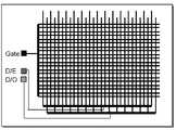
도 6a 내지 6d는 본 발명에 따라 검사할 수 있는 평판 디스플레이의 패널 모양을 설명하기 위한 개략적인 도면으로서, 게이트 전극라인들과 데이터 전극라인들이 교차되어 있고, 상기 게이트 전극라인들과 연결된 게이트 전극 패드와 상기 데이터 전극라인들과 연결된 데이터 전극 패드이 형성되어 있는 도 6a에 도시된 바와 같은 평판 디스플레이 패널의 전극라인들을 검사할 수 있다.6A through 6D are schematic views illustrating a panel shape of a flat panel display that can be inspected according to an exemplary embodiment of the present invention, in which gate electrode lines and data electrode lines are intersected, and gate electrode pads connected to the gate electrode lines. And electrode lines of the flat panel display panel as illustrated in FIG. 6A, in which data electrode pads connected to the data electrode lines are formed.
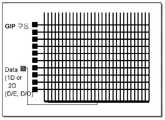
그리고, 게이트 전극라인들과 그의 패드 및 2개의 데이터 전극라인들과 그들의 패드들이 형성된 평판 디스플레이 패널(도 6b), 2개의 게이트 전극라인들과 패드들 및 2개의 데이터 전극라인들과 패드들이 형성된 평판 디스플레이 패널(도 6c) 및 GIP(Gate In Panel) 구동용 게이트 전극라인들과 패드들 및 1개 또는 2개의 데이터 전극라인들과 패드들이 형성된 평판 디스플레이 패널(도 6d)을 검사할 수 있다.And a flat panel display panel (FIG. 6B) in which gate electrode lines and pads thereof and two data electrode lines and pads are formed, a flat plate in which two gate electrode lines and pads and two data electrode lines and pads are formed. A flat panel display panel (FIG. 6D) in which gate electrode lines and pads for driving a display panel (FIG. 6C) and a gate in panel (GIP) and one or two data electrode lines and pads is formed may be inspected.
본 발명은 전술된 바와 같이 이러한 평판 디스플레이 패널의 전극라인들에 신호를 인가하고, 전계 센서 또는 자계 센서를 이용하여 교차 단락(Cross short) 신호의 변화를 감지함으로써, 결함된 라인의 위치를 정확하게 검출할 수 있다.The present invention accurately detects the position of a defective line by applying a signal to the electrode lines of such a flat panel display panel and detecting a change in a cross short signal using an electric field sensor or a magnetic field sensor as described above. can do.
그리고, 도 6d의 GIP 구동용 게이트 전극라인들 경우, 순차적으로 게이트 전극라인들에 신호를 인가하면서, 게이트 전극라인들과 데이터 전극라인들 간의 교차 단락에 대한 신호 변화를 감지하여 결함된 위치를 검출하게 된다.In the GIP driving gate electrode lines of FIG. 6D, while a signal is sequentially applied to the gate electrode lines, a defective position is detected by detecting a signal change for a cross short between the gate electrode lines and the data electrode lines. Done.
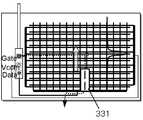
도 7a 내지 7d는 본 발명에 따라 전계 센서를 이용하여 평판 디스플레이의 전극 라인들의 결함 위치를 검출하는 방법을 설명하기 위한 개략적인 도면으로서, 전계 센서는 송신부와 수신부로 구성할 수 있으며, 도 7a와 7b는 프로브 유닛을 전계 센서의 송신부로 활용하고, 전계 센서의 수신부를 이동시키면서 전극 라인들의 결함 위치를 찾아내는 것이다.7A to 7D are schematic views for explaining a method of detecting a defect location of electrode lines of a flat panel display using an electric field sensor according to the present invention. The electric field sensor may be configured as a transmitter and a receiver. 7b utilizes the probe unit as a transmitter of the field sensor, and finds a defective position of the electrode lines while moving the receiver of the field sensor.
즉, 도 7a 및 도 7b에서 전계 센서의 송신부는 평판 디스플레이 패널에 접촉 되어 있고, 수신부는 접촉되어 있지 않는 상태이다.That is, in FIGS. 7A and 7B, the transmitter of the field sensor is in contact with the flat panel display panel and the receiver is not in contact.
그러므로, 전극라인들에 신호가 인가되었을 때의 전류 흐름을 따라 전계 센서의 수신부(330,331)로 스캔하면, 신호의 변화가 발생되는 지점을 검출할 수 있게 된다.Therefore, when the signal is applied to the electrode lines and scanned with the
이러한 전계 센서의 수신부(330,331) 각각은 두 개의 신호 변화 차이를 구별할 수 있는 차동 수신부로 구성하여 전극라인들이 교차되는 지점에서 최대 신호 변화가 되도록 하여 검출할 수 있다.Each of the
예컨대, 전계 센서의 수신부로 스캔할 때, 정상적인 전극라인 지점에서는 두 개의 신호가 1,1이 되고, 신호의 차이가 'O'으로 검출되고, 결함이 있는 지점에서는 1,0이 됨으로, 신호의 차이가 '1'로 검출된다.For example, when scanning with a receiver of an electric field sensor, two signals become 1, 1 at a normal electrode line point, and a difference of signals is detected as 'O', and at a defective point, it becomes 1,0, The difference is detected as '1'.
그러므로, 결함이 있는 전극라인의 위치를 검출할 수 있게 된다.Therefore, the position of the defective electrode line can be detected.
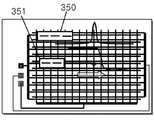
그리고, 도 7c와 7d와 같이, 전계 센서의 송신부 및 수신부를 평판 디스플레이 패널이 접촉되지 않도록 하여 신호 변화가 발생되는 지점을 검출할 수 있다.As illustrated in FIGS. 7C and 7D, it is possible to detect a point where a signal change occurs by preventing the flat panel display panel from contacting the transmitter and the receiver of the field sensor.
이때, 전계 센서의 송신부와 수신부는 일체로 형성되어, 하나의 송신부와 두 개의 신호 변화 차이를 구별할 수 있는 차동 수신부로 이루어진 전계 센서(350,360) 및 각각 하나의 송신부와 수신부로 이루어진 전계 센서(351,361)로 구성할 수 있다.At this time, the transmitter and the receiver of the electric field sensor are integrally formed, and the
그러므로, 본 발명은 전계 센서로 스캔하면, 정상적인 전극 라인에서는 특정 신호가 검출되다가 결함을 벗어나면 신호가 변하게 되고, 그 신호가 변하는 위치를 결함 위치로 추출하고 카메라를 이용하여 결함 위치를 확인한 후 결함으로 결정할 수 있는 것이다.Therefore, in the present invention, when scanning with an electric field sensor, a specific signal is detected in a normal electrode line and the signal is changed when it is out of the defect, the position where the signal is changed is extracted into the defect position, and the defect position is confirmed using a camera. You can decide.
도 8a와 8b는 본 발명에 따라 전계 센서를 이용하여 평판 디스플레이의 전극 라인들의 결함 위치를 검출하는 다른 방법을 설명하기 위한 개략적인 도면으로서, 이 방법은 평판 디스플레이 패널에 비접촉되는 전계 센서를 이용하여 전극 라인들의 결함 위치를 검출하는 것이다.8A and 8B are schematic diagrams for explaining another method of detecting a defective position of electrode lines of a flat panel display using an electric field sensor according to the present invention, which uses a field sensor that is not in contact with the flat panel display panel. It is to detect the defective position of the electrode lines.
먼저, 도 8a에 도시된 바와 같이, 전계 센서의 송신부(371)와 수신부(372)를 수직하게 배치하고, 전계 센서의 송신부(371)의 스캔 방향과 수신부(372)의 스캔 방향이 수직 교차되도록 배치하여 스캔하면 교차 단락 결함(Cross short defect)가 발생한 전극라인에서 최대 신호가 감지되고, 그 최대 신호가 감지된 지점에서 결함 위치를 찾을 수 있게 된다.First, as shown in FIG. 8A, the
그리고, 도 8a의 반대 방향으로 전계 센서의 송신부(371)와 수신부(372)를 수직하게 배치하여 스캔할 수 있다.In addition, the
또한, 도 8b에서는 송신부와 수신부는 일체로 형성되어 있는 한 쌍의 전계 센서들(381,382)을 수직하게 교차되도록 배치하여 스캔함으로써, 결함 위치를 검출하는 것이다.In addition, in FIG. 8B, the transmitter and the receiver are configured to scan a pair of
즉, 수직하게 배치되어 있는 제 1 전계 센서(381)와 제 2 전계 센서(282) 각각은 송신부와 수신부가 구비되어 있는 것이다.That is, each of the
그리고, 상기 제 1 전계 센서(381)의 송신부에서 송신된 제 1 신호는 상기 제 2 전계 센서(382)의 수신부에서 수신되고, 상기 제 2 전계 센서(382)의 송신부 에서 수신된 제 2 신호는 상기 제 1 전계 센서(381)의 수신부에서 수신되어 스캔된 신호를 검출하게 된다.The first signal transmitted from the transmitter of the
이때, 상기 제 1 신호와 제 2 신호는 주파수가 상이한 신호들이며, 상기 제 1 신호와 제 2 신호의 주파수가 상이해야, 제 1 전계 센서(381)와 제 2 전계 센서(282)에서 검출되는 신호가 간섭되는 것을 방지할 수 있는 것이다.In this case, the first signal and the second signal are signals having different frequencies, and the signals detected by the
또, 도 8a와 8b의 '500'은 카메라의 촬영 영역이다.Also, '500' in FIGS. 8A and 8B is a photographing area of the camera.
도 9는 본 발명에 따라 자계 센서 또는 전계 센서 및 카메라가 배치된 상태를 설명하기 위한 개략적인 도면으로서, 카메라(530) 및 전계 센서 또는 자계 센서(551,552,561,562)는 이동할 수 있는 구동부에 장착되어 있다.FIG. 9 is a schematic view illustrating a state in which a magnetic field sensor or an electric field sensor and a camera are disposed according to the present invention, and the
이때, 상기 전계 센서 또는 자계 센서(551,552,561,562)는 직교하는 두 선상(P1,P2)에 배치되어 있고, 상기 두 선상(P1,P2)이 교차하는 지점에 상기 카메라(530)가 배치되어 있다.In this case, the electric field sensor or the
그리고, 상기 전계 센서 또는 자계 센서(551,552,561,562)는 도 9의 화살표 방향으로 스캔할 수 있도록 이동 가능하게 구성되어 있는 것이 바람직하다.In addition, the electric field sensor or the
따라서, 상기 전계 센서 또는 자계 센서(551,552,561,562)로 전기적 결함이 있는 전극라인의 자기장 또는 전기장을 검출하여 상기 전극라인의 결함 위치를 추출한 후, 상기 전극라인의 결함 위치를 상기 카메라(530)로 촬영하여 영상을 획득할 수 있는 것이므로, 상기 전계 센서 또는 자계 센서(551,552,561,562)가 스캔하는 라인의 교차점에 카메라가 존재하여 결함이 있는 지점을 쉽게 촬영할 수 있게 된다.Accordingly, the magnetic field or the electric field of the electrode line having an electrical defect is detected by the electric field sensor or the
도 10은 본 발명에 따른 평판 디스플레이의 전극라인을 다른 방법으로 검사하기 위한 플로우챠트로서, 이 검사 방법은 먼저, 프로브 유닛의 프로브들을 평판 디스플레이의 전극라인들에 컨택한다.(S210단계)10 is a flowchart for inspecting the electrode line of the flat panel display according to the present invention by another method, which first contacts the probes of the probe unit with the electrode lines of the flat panel display (step S210).
그 다음, 상기 프로브 유닛을 통하여 상기 전극라인들에 신호를 인가한다.(S220단계)Then, a signal is applied to the electrode lines through the probe unit (S220).
그 후, 상기 전극라인들에 인가된 신호로 상기 전극라인들에 전기적인 결함이 있는지 여부를 판단한다.(S230단계)Thereafter, it is determined whether there is an electrical defect in the electrode lines based on the signal applied to the electrode lines (step S230).
이어서, 상기 전극라인들에 전기적인 결함이 있는 경우, 자계 센서들로 전극라인들을 스캔한다.(S240단계)Subsequently, if there is an electrical defect in the electrode lines, the electrode lines are scanned with magnetic field sensors (S240).
여기서, 상기 전극라인들에 전기적인 결함이 없는 경우는 평판 디스플레이의 전극라인들에 전기적인 결함이 없는 것으로 간주된다.Here, when there is no electrical defect in the electrode lines, it is considered that there is no electrical defect in the electrode lines of the flat panel display.
계속, 상기 자계 센서들에서 검출된 신호에서 최대 신호가 있는지 여부를 판단한다.(S250단계)In operation S250, it is determined whether there is a maximum signal from the signals detected by the magnetic field sensors.
연이어, 상기 자계 센서들에서 검출된 신호가 최대 신호가 있는 경우, 최대 신호가 발생된 전극라인의 위치를 전기적인 결함이 있는 위치로 추출한다.(S260단계)Subsequently, when the signals detected by the magnetic field sensors have a maximum signal, the position of the electrode line where the maximum signal is generated is extracted as a location having an electrical defect (S260).
이후, 상기 전기적인 결함이 있는 위치를 카메라로 촬영하여 영상을 획득하고, 획득된 영상을 분석하여 결함 위치를 결정한다.(S290단계)Subsequently, an image is obtained by photographing the position of the electrical defect with a camera, and the defect position is determined by analyzing the acquired image.
그리고, 상기 자계 센서들에서 검출된 신호에서 최대 신호가 없는 경우, 전계 센서들로 전극라인들을 근접 스캔한다.(S270단계)When there is no maximum signal in the signals detected by the magnetic field sensors, the electrode lines are closely scanned to the field sensors (step S270).
그 다음, 상기 전계 센서들에서 검출된 신호에서 신호의 변화가 발생된 전극라인의 위치를 전기적인 결함이 있는 위치로 추출한다.(S280단계)Next, the position of the electrode line where the change of the signal is generated from the signals detected by the electric field sensors is extracted to the position where there is an electrical defect (step S280).
상기 280단계 다음에는 상기 290단계를 수행한다.After step 280, step 290 is performed.
한편, 상기 자계 센서들로 스캔하는 'S240단계'는 1차 자계 센서들로 전극라인들을 스캔하여 결함이 있는 전극라인들을 추출하는 단계와; 그 추출된 결함이 있는 전극라인들 근처에서 2차 자계 센서들로 근접 스캔하는 단계로 이루어진 것이 바람직하다.Meanwhile, step S240 of scanning with the magnetic field sensors may include extracting defective electrode lines by scanning electrode lines with primary magnetic field sensors; Proximity scanning with secondary magnetic field sensors near the extracted defective electrode lines is preferred.
또한, 본 발명은 전술된 평판 디스플레이의 전극라인 검사 방법에서, 결함 위치를 결정한 후, 결함이 있는 전극라인을 리페어하는 공정이 더 구비된 것이 바람직하다.In addition, the present invention preferably further comprises a step of repairing the defective electrode line after determining the defect position in the electrode line inspection method of the flat panel display described above.
본 발명은 구체적인 예에 대해서만 상세히 설명되었지만 본 발명의 기술사상 범위 내에서 다양한 변형 및 수정이 가능함은 당업자에게 있어서 명백한 것이며, 이러한 변형 및 수정이 첨부된 특허청구범위에 속함은 당연한 것이다.Although the invention has been described in detail only with respect to specific examples, it will be apparent to those skilled in the art that various modifications and variations are possible within the spirit of the invention, and such modifications and variations belong to the appended claims.
도 1a와 1b는 일반적인 플라즈마 디스플레이 패널의 평판 전극의 결함 상태를 설명하기 위한 개략도1A and 1B are schematic diagrams for describing a defect state of a flat plate electrode of a typical plasma display panel.
도 2는 일반적인 액정 디스플레이 TN 모드의 평판 전극의 결함 상태를 설명하기 위한 개략도2 is a schematic diagram for explaining a defect state of a flat electrode of a general liquid crystal display TN mode;
도 3은 본 발명에 따른 평판 디스플레이의 전극라인 검사 장치의 개략적인 구성 블록도3 is a schematic block diagram of an electrode line inspection apparatus of a flat panel display according to the present invention;
도 4는 본 발명에 따른 평판 디스플레이의 전극라인 검사 방법의 개략적인 흐름도4 is a schematic flowchart of an electrode line inspection method of a flat panel display according to the present invention;
도 5a와 5b는 본 발명에 따라 평판 디스플레이의 결함 라인을 검사하는 방법을 설명하기 위한 개략적인 도면5A and 5B are schematic diagrams for explaining a method for inspecting a defect line of a flat panel display according to the present invention.
도 6a 내지 6d는 본 발명에 따라 검사할 수 있는 평판 디스플레이의 패널 모양을 설명하기 위한 개략적인 도면6A-6D are schematic diagrams for explaining the panel shape of a flat panel display that can be inspected according to the present invention;
도 7a 내지 7d는 본 발명에 따라 전계 센서를 이용하여 평판 디스플레이의 전극 라인들의 결함 위치를 검출하는 방법을 설명하기 위한 개략적인 도면7A to 7D are schematic diagrams for explaining a method of detecting a defect position of electrode lines of a flat panel display using an electric field sensor according to the present invention;
도 8a와 8b는 본 발명에 따라 전계 센서를 이용하여 평판 디스플레이의 전극 라인들의 결함 위치를 검출하는 다른 방법을 설명하기 위한 개략적인 도면8A and 8B are schematic diagrams for explaining another method of detecting a defective position of electrode lines of a flat panel display using an electric field sensor according to the present invention;
도 9는 본 발명에 따라 자계 센서 또는 전계 센서 및 카메라가 배치된 상태를 설명하기 위한 개략적인 도면9 is a schematic diagram for explaining a state in which a magnetic field sensor or an electric field sensor and a camera are disposed according to the present invention;
도 10은 본 발명에 따른 평판 디스플레이의 전극라인을 다른 방법으로 검사 하기 위한 플로우챠트10 is a flow chart for inspecting the electrode line of the flat panel display according to the present invention in another method
Claims (17)
Translated fromKoreanPriority Applications (3)
| Application Number | Priority Date | Filing Date | Title |
|---|---|---|---|
| KR1020080087232AKR20100028275A (en) | 2008-09-04 | 2008-09-04 | Apparatus and method for inspecting electrode lines of falt panel display |
| TW098128563ATW201011291A (en) | 2008-09-04 | 2009-08-25 | Apparatus and method for inspecting electrode lines of flat panel display |
| CN200910168373ACN101666845A (en) | 2008-09-04 | 2009-08-31 | Apparatus and method for examining electrode wire for flat-panel display |
Applications Claiming Priority (1)
| Application Number | Priority Date | Filing Date | Title |
|---|---|---|---|
| KR1020080087232AKR20100028275A (en) | 2008-09-04 | 2008-09-04 | Apparatus and method for inspecting electrode lines of falt panel display |
Publications (1)
| Publication Number | Publication Date |
|---|---|
| KR20100028275Atrue KR20100028275A (en) | 2010-03-12 |
Family
ID=41803549
Family Applications (1)
| Application Number | Title | Priority Date | Filing Date |
|---|---|---|---|
| KR1020080087232AWithdrawnKR20100028275A (en) | 2008-09-04 | 2008-09-04 | Apparatus and method for inspecting electrode lines of falt panel display |
Country Status (3)
| Country | Link |
|---|---|
| KR (1) | KR20100028275A (en) |
| CN (1) | CN101666845A (en) |
| TW (1) | TW201011291A (en) |
Cited By (6)
| Publication number | Priority date | Publication date | Assignee | Title |
|---|---|---|---|---|
| CN102854679A (en)* | 2012-09-25 | 2013-01-02 | 南京中电熊猫液晶显示科技有限公司 | Liquid crystal display panel and repairing method thereof |
| KR101223930B1 (en)* | 2012-02-06 | 2013-02-05 | 로체 시스템즈(주) | Contact type electrode pattern inspection apparatus |
| KR101259350B1 (en)* | 2012-02-24 | 2013-04-30 | 로체 시스템즈(주) | Electrode pattern inspection device with T-type sensor |
| WO2013119014A1 (en)* | 2012-02-06 | 2013-08-15 | 로체 시스템즈(주) | Electrode pattern test apparatus |
| KR20140067454A (en)* | 2012-11-26 | 2014-06-05 | 엘지디스플레이 주식회사 | Method and apparatus for testing flat panel display |
| WO2017111515A1 (en)* | 2015-12-22 | 2017-06-29 | 주식회사 포스코 | Apparatus and method for inspecting steel plate |
Families Citing this family (5)
| Publication number | Priority date | Publication date | Assignee | Title |
|---|---|---|---|---|
| KR101275815B1 (en)* | 2011-03-15 | 2013-06-18 | 삼성에스디아이 주식회사 | Apparatus for detecting defects in the electrode material for secondary battery and method for the same |
| CN103472601B (en)* | 2013-09-02 | 2016-06-15 | 京东方科技集团股份有限公司 | A kind of detection equipment and detection method |
| CN106124917A (en)* | 2016-08-17 | 2016-11-16 | 深圳晶华显示器材有限公司 | A kind of probe test LCD short-circuiting means |
| CN107607800A (en)* | 2017-10-20 | 2018-01-19 | 国网四川省电力公司电力科学研究院 | A kind of emergence measuring method of project of transmitting and converting electricity power frequency electric field under high humidity environment |
| CN115810317B (en)* | 2021-09-13 | 2025-03-18 | 重庆康佳光电科技有限公司 | Circuit backplane detection device and circuit backplane detection method |
- 2008
- 2008-09-04KRKR1020080087232Apatent/KR20100028275A/ennot_activeWithdrawn
- 2009
- 2009-08-25TWTW098128563Apatent/TW201011291A/enunknown
- 2009-08-31CNCN200910168373Apatent/CN101666845A/enactivePending
Cited By (9)
| Publication number | Priority date | Publication date | Assignee | Title |
|---|---|---|---|---|
| KR101223930B1 (en)* | 2012-02-06 | 2013-02-05 | 로체 시스템즈(주) | Contact type electrode pattern inspection apparatus |
| WO2013119014A1 (en)* | 2012-02-06 | 2013-08-15 | 로체 시스템즈(주) | Electrode pattern test apparatus |
| CN104105975A (en)* | 2012-02-06 | 2014-10-15 | 罗泽系统株式会社 | Electrode pattern test apparatus |
| CN104105975B (en)* | 2012-02-06 | 2016-03-30 | 罗泽系统株式会社 | Electrode pattern proving installation |
| KR101259350B1 (en)* | 2012-02-24 | 2013-04-30 | 로체 시스템즈(주) | Electrode pattern inspection device with T-type sensor |
| WO2013125864A1 (en)* | 2012-02-24 | 2013-08-29 | 로체 시스템즈(주) | Electrode pattern inspection device |
| CN102854679A (en)* | 2012-09-25 | 2013-01-02 | 南京中电熊猫液晶显示科技有限公司 | Liquid crystal display panel and repairing method thereof |
| KR20140067454A (en)* | 2012-11-26 | 2014-06-05 | 엘지디스플레이 주식회사 | Method and apparatus for testing flat panel display |
| WO2017111515A1 (en)* | 2015-12-22 | 2017-06-29 | 주식회사 포스코 | Apparatus and method for inspecting steel plate |
Also Published As
| Publication number | Publication date |
|---|---|
| TW201011291A (en) | 2010-03-16 |
| CN101666845A (en) | 2010-03-10 |
Similar Documents
| Publication | Publication Date | Title |
|---|---|---|
| KR20100028275A (en) | Apparatus and method for inspecting electrode lines of falt panel display | |
| KR100799161B1 (en) | Non-contact single side probe and device for detecting disconnection and short circuit of pattern electrode using same and method | |
| KR101633514B1 (en) | Circuit pattern inspection device and circuit pattern inspection method thereof | |
| CN102253550B (en) | Method and apparatus for inspecting liquid crystal display device | |
| KR20020001752A (en) | Tester and testing method, and testing unit | |
| TWI401452B (en) | Circuit pattern inspection device and inspection method | |
| HK1256934A1 (en) | Method for detecting defects of thin-film transistor panel and device thereof | |
| WO2014201794A1 (en) | Array substrate line detection device and detection method | |
| TWI474012B (en) | Detecting device of conductive pattern and detecting method | |
| KR20080098088A (en) | Non-contact single side probe and device for detecting disconnection and short circuit of pattern electrode using same and method | |
| TW200537112A (en) | Circuit pattern testing apparatus and circuit pattern testing method | |
| KR101264765B1 (en) | Conductive pattern inspection device | |
| KR20130121400A (en) | Non-contact resistance checker | |
| KR100627546B1 (en) | Device for detecting disconnection / short-circuit position of plate circuit electrode line using magnetic sensor and camera and its method | |
| CN109073695A (en) | The inspection method and inspection system of the wiring path of substrate | |
| KR101489369B1 (en) | Bump film and probe block tester | |
| KR102546454B1 (en) | How to detect defects in super high resolution panels | |
| KR100416962B1 (en) | Non contact type voltage sensing apparatus | |
| JP2010008996A (en) | Device and method for forming contactless contact of conductive structure, particularly, thin film transistor liquid crystal display | |
| JPH10206481A (en) | Substrate inspection equipment | |
| JP2013217841A (en) | Conductive pattern inspection device | |
| KR20070078292A (en) | Apparatus and method for defect detection of electrode lines for flat panel display devices | |
| TWI418814B (en) | Conductive pattern inspection device | |
| CN112327527A (en) | Device and method for positioning abnormal position of line | |
| KR20070027095A (en) | Non-contact wire defect inspection device and inspection method |
Legal Events
| Date | Code | Title | Description |
|---|---|---|---|
| PA0109 | Patent application | Patent event code:PA01091R01D Comment text:Patent Application Patent event date:20080904 | |
| PG1501 | Laying open of application | ||
| PC1203 | Withdrawal of no request for examination | ||
| WITN | Application deemed withdrawn, e.g. because no request for examination was filed or no examination fee was paid |