KR20100021999A - Adaptive dynamic reading of flash memories - Google Patents
Adaptive dynamic reading of flash memoriesDownload PDFInfo
- Publication number
- KR20100021999A KR20100021999AKR1020097022802AKR20097022802AKR20100021999AKR 20100021999 AKR20100021999 AKR 20100021999AKR 1020097022802 AKR1020097022802 AKR 1020097022802AKR 20097022802 AKR20097022802 AKR 20097022802AKR 20100021999 AKR20100021999 AKR 20100021999A
- Authority
- KR
- South Korea
- Prior art keywords
- threshold voltage
- cell
- cells
- reading
- voltage
- Prior art date
- Legal status (The legal status is an assumption and is not a legal conclusion. Google has not performed a legal analysis and makes no representation as to the accuracy of the status listed.)
- Granted
Links
Images


Classifications
- G—PHYSICS
- G11—INFORMATION STORAGE
- G11C—STATIC STORES
- G11C16/00—Erasable programmable read-only memories
- G11C16/02—Erasable programmable read-only memories electrically programmable
- G11C16/06—Auxiliary circuits, e.g. for writing into memory
- G11C16/34—Determination of programming status, e.g. threshold voltage, overprogramming or underprogramming, retention
- G—PHYSICS
- G11—INFORMATION STORAGE
- G11C—STATIC STORES
- G11C16/00—Erasable programmable read-only memories
- G11C16/02—Erasable programmable read-only memories electrically programmable
- G11C16/06—Auxiliary circuits, e.g. for writing into memory
- G11C16/10—Programming or data input circuits
- G—PHYSICS
- G11—INFORMATION STORAGE
- G11C—STATIC STORES
- G11C11/00—Digital stores characterised by the use of particular electric or magnetic storage elements; Storage elements therefor
- G11C11/56—Digital stores characterised by the use of particular electric or magnetic storage elements; Storage elements therefor using storage elements with more than two stable states represented by steps, e.g. of voltage, current, phase, frequency
- G11C11/5621—Digital stores characterised by the use of particular electric or magnetic storage elements; Storage elements therefor using storage elements with more than two stable states represented by steps, e.g. of voltage, current, phase, frequency using charge storage in a floating gate
- G11C11/5628—Programming or writing circuits; Data input circuits
- G—PHYSICS
- G11—INFORMATION STORAGE
- G11C—STATIC STORES
- G11C11/00—Digital stores characterised by the use of particular electric or magnetic storage elements; Storage elements therefor
- G11C11/56—Digital stores characterised by the use of particular electric or magnetic storage elements; Storage elements therefor using storage elements with more than two stable states represented by steps, e.g. of voltage, current, phase, frequency
- G11C11/5621—Digital stores characterised by the use of particular electric or magnetic storage elements; Storage elements therefor using storage elements with more than two stable states represented by steps, e.g. of voltage, current, phase, frequency using charge storage in a floating gate
- G11C11/5642—Sensing or reading circuits; Data output circuits
- G—PHYSICS
- G11—INFORMATION STORAGE
- G11C—STATIC STORES
- G11C16/00—Erasable programmable read-only memories
- G11C16/02—Erasable programmable read-only memories electrically programmable
- G11C16/06—Auxiliary circuits, e.g. for writing into memory
- G11C16/10—Programming or data input circuits
- G11C16/12—Programming voltage switching circuits
- G—PHYSICS
- G11—INFORMATION STORAGE
- G11C—STATIC STORES
- G11C16/00—Erasable programmable read-only memories
- G11C16/02—Erasable programmable read-only memories electrically programmable
- G11C16/06—Auxiliary circuits, e.g. for writing into memory
- G11C16/26—Sensing or reading circuits; Data output circuits
- G11C16/28—Sensing or reading circuits; Data output circuits using differential sensing or reference cells, e.g. dummy cells
- G—PHYSICS
- G11—INFORMATION STORAGE
- G11C—STATIC STORES
- G11C16/00—Erasable programmable read-only memories
- G11C16/02—Erasable programmable read-only memories electrically programmable
- G11C16/06—Auxiliary circuits, e.g. for writing into memory
- G11C16/30—Power supply circuits
- G—PHYSICS
- G11—INFORMATION STORAGE
- G11C—STATIC STORES
- G11C2211/00—Indexing scheme relating to digital stores characterized by the use of particular electric or magnetic storage elements; Storage elements therefor
- G11C2211/56—Indexing scheme relating to G11C11/56 and sub-groups for features not covered by these groups
- G11C2211/563—Multilevel memory reading aspects
- G11C2211/5634—Reference cells
Landscapes
- Engineering & Computer Science (AREA)
- Computer Hardware Design (AREA)
- Read Only Memory (AREA)
Abstract
Translated fromKoreanDescription
Translated fromKorean본 발명은, 셀당 다중 비트 플래시 메모리(multi-bit-per-cell flash memory)에 관한 것이고, 보다 구체적으로는 셀당 다중 비트 플래시 메모리에 대한 판독 기준 전압을 최적화시키는 방법에 관한 것이다.The present invention relates to multi-bit-per-cell flash memory, and more particularly to a method of optimizing read reference voltage for multi-bit flash memory per cell.
원래, 플래시 메모리는 셀당 하나의 비트만을 저장했었다. 현재 셀당 2비트를 저장하는 플래시 메모리들이 상업적으로 이용 가능하고 셀당 2 이상의 비트를 저장하는 플래시 메모리들이 개발되고 있다. 종래에, 셀 탕 1비트를 저장하는 플래시 메모리를 "싱글 레벨 셀"(SLC, Single Level Cell) 메모리라 하고 셀당 1 이상의 비트를 저장하는 플래시 메모리를 "다중 레벨 셀"(MLC, Multi Level Cell)메모리라 한다. 그런데 실질적으로 SLC 메모리는 저장된 단일 비트가 "1"비트 또는 "0"비트인지를 표시하기 위해 두 개의 레벨을 갖기 때문에 이러한 명명법은 잘못된 것이다. 그러므로, 여기서는 이 두 종류의 메모리를 "싱글 비트 셀"(SBC, Single Bit Cell) 메모리 및 "다중 비트 셀"(MBC, Multi Bit Cell)이라 한다.Originally, flash memory only stored one bit per cell. Flash memories that store two bits per cell are now commercially available and flash memories are being developed that store two or more bits per cell. Conventionally, a flash memory that stores one bit of a cell is called a "single level cell" (SLC) memory, and a flash memory that stores one or more bits per cell is called a "multi level cell" (MLC). It is called memory. In practice, this nomenclature is wrong because SLC memory has two levels to indicate whether a single stored bit is a "1" bit or a "0" bit. Therefore, these two types of memory are referred to herein as "single bit cell" (SBC) memories and "multi bit cells" (MBC).
도 1은 셀당 3비트를 저장할 수 있는 MBC 메모리에 3비트의 비트 패턴이 어떻게 저장되는지를 설명하고 있다.1 illustrates how a 3-bit bit pattern is stored in an MBC memory capable of storing 3 bits per cell.
플래시 셀의 문턱 전압은 최소 Vmin 내지 되대 Vmax의 범위에 있고, 이를 "전압창(voltage window)"이라고 한다. 역사적인 이유로, 플래시 셀에 데이터를 기록하는 것을 플래시 셀을 "프로그래밍"한다고 한다 (여기서, 상기 용어 "기록" 및 "프로그래밍"은 상호 교체가 가능하다). 이 작업은, 원하는 비트 패턴을 나타내기 위해 셀의 문턱 전압이 전압창 내에서 충분히 높아질 때까지, 상기 셀의 실리콘 기판으로부터 상기 셀의 산화막을 통해 상기 셀의 플로팅 게이트로 전자를 주입하기 위해 전압펄스를 상기 셀에 가함으로써 실시된다. 3중셀(three-bit-per-cell) 메모리에서, 상기 전압창은 여덟 개의 전압 대역으로 구분된다: Vmin ~ V1, V1 ~ V2, V2 ~ V3, V3 ~V4, V4 ~ V5, V5 ~ V6, V6 ~ V7, 및 V7 ~ Vmax. 상기 전압 대역 중 한 대역 내의 문턱 전압은 도 1에 도시한 바와 같이 비트 패턴을 나타낸다:Vmin ~ V1사이의 문턱 전압은 비트 패턴(111)을 나타내고 V1 ~ V2 사이의 문턱 전압은 비트 패턴"110"을 나타낸다. 일반적으로, m중 메모리의 전압창은 2m 전압 밴드로 구분된다.The threshold voltage of the flash cell is in the range of at least Vmin to back Vmax , which is referred to as a "voltage window". For historical reasons, writing data to a flash cell is referred to as "programming" the flash cell (where the terms "write" and "programming" are interchangeable). This operation involves applying a voltage pulse to inject electrons from the cell's silicon substrate through the cell's oxide film into the cell's floating gate until the cell's threshold voltage is sufficiently high in the voltage window to represent the desired bit pattern. Is applied to the cell. In three-bit-per-cell memory, the voltage window is divided into eight voltage bands: Vmin to V1 , V1 to V2 , V2 to V3 , V3 to V4 , V4 to V5 , V5 to V6 , V6 to V7 , and V7 to Vmax . A threshold voltage in one of the voltage bands represents a bit pattern as shown in FIG. 1: a threshold voltage between Vmin and V1 represents a
플래시 셀을 읽기 위해 상기 플래시 셀의 문턱 전압과, 상기 전압 대역을 정의하는 기준 전압을 비교한다. 일부 플래시 메모리의 경우(이하, "제 1형" 메모리라 한다), m 비트의 비트 패턴을 저장하고 있는 셀을 읽기 위해서는 m번의 비교가 필요하다. 예를 들어 m=3인 경우, 도 1에 도시한 바와 같이, 우선 문턱 전압과 V4를 비교한다. 상기 비교결과에 따라 문턱 전압을 V2 또는 V6와 비교한다. 상기 두 번째 비교 결과에 따라 상기 문턱 전압을 V1, V3, V5, 또는 V7과 비교한다. 물론, 이러한 비교는 상기 문턱 전압의 사전 지식을 요하지는 않는다: 상기 플래시 메모리의 회로소자는 상기 문턱 전압이 기준 전압보다 높은지 또는 낮은지를 나타내는 신호를 그것이 비교되는 곳으로 반환한다.To read a flash cell, a threshold voltage of the flash cell is compared with a reference voltage defining the voltage band. In some flash memories (hereinafter referred to as "
일부 기타 플래시 메모리의 경우(이하, "제 2형" 메모리라 한다), 공동을 판독되는 모든 셀의 문턱 전압을 Vmin과 Vmax 사이의 모든 2m-1 기준 전압과 비교한다.For some other flash memories (hereinafter referred to as "
일 그룹의 플래시 셀에서, 상기 셀들의 문턱 전압은 각각의 전압 대역의 중앙을 기준으로 통계학적으로 분포된다. 도 1은 분포 곡선(10)을 따라 분포된 제 1 전압 대역에서의 문턱 전압, 분포 곡선(12)을 따라 분포된 제 2 전압 대역에서의 문턱 전압, 분포 곡선(14)을 따라 분포된 제 3 전압 대역에서의 문턱 전압, 분포 곡선(16)을 따라 분포된 제 4 전압 대역에서의 문턱 전압, 분포 곡선(18)을 따라 분포된 제 5 전압 대역에서의 문턱 전압, 분포 곡선(20)을 따라 분포된 제 6 전압 대역에서의 문턱 전압, 분포 곡선(22)을 따라 분포된 제 7 전압 대역에서의 문턱 전압, 및 분포 곡선(24)을 따라 분포된 제 8 전압 대역에서의 문턱 전압을 도시하고 있다. 이러한 분포 전압의 폭이 한정되는 데에는 여러 가지 이유가 있다.In a group of flash cells, the threshold voltages of the cells are statistically distributed with respect to the center of each voltage band. 1 shows a threshold voltage in a first voltage band distributed along a
1. 프로그래밍 과정이, 양자역학적 터널링(quantum mechanical tunneling) 및 고온 사출(hot injection)과 같은 본질적으로 확률적인 처리에 의존하는 확률론적이다.1. The programming process is probabilistic, which relies on inherently stochastic processes such as quantum mechanical tunneling and hot injection.
2. 판독/프로그램 회로의 정확성에 한계가 있고 랜덤노이즈에 의해 제한된 다.2. The accuracy of the read / program circuit is limited and limited by random noise.
3. 일부 플래시 기술에서 판독되고 있는 셀의 문턱 전압이 인접 셀의 문턱 전압에 영향을 받는다.3. In some flash technologies, the threshold voltage of a cell being read is affected by the threshold voltage of adjacent cells.
4. 칩대칩 편차(chip-to-chip variation) 및 제조공정에 의해 셀이 판독/프로그래밍시 다른 셀과 다른 성질을 나타낸다.4. Due to chip-to-chip variation and manufacturing process, a cell exhibits different properties from other cells when read / programmed.
또한, 문턱 전압 분포는 시간의 경과에 따라 다음과 같은 경향을 보인다.In addition, the threshold voltage distribution shows the following tendency with time.
1. 플래시 메모리가 프로그램되고 삭제됨에 따라, 전압창은 수축하고 전압 대역은 편향되는 경향이 있다. 이러한 현상은 MBC 플래시 메모리의 삭제 및 재프로그래밍 횟수를 제한하게 된다.1. As the flash memory is programmed and erased, the voltage window tends to contract and the voltage bands are biased. This phenomenon limits the number of erase and reprogramming of MBC flash memory.
2. 오랫동안 프로그래밍하지 않은 플래시 셀은 문턱 전압이 떨어지는 경향이 있다. 이러한 현상은 데이터가 플래시 메모리에 신뢰성 있게 유지될 수 있는 시간을 제한하게 된다.2. Flash cells that have not been programmed for a long time tend to have lower threshold voltages. This phenomenon limits the time that data can remain reliably in flash memory.
플래시 셀의 전압 대역은 이러한 모든 현상을 수용할 수 있을 정도로 충분히 넓게, 하지만 너무 넓지는 않게 설계되어야 한다. 해당 문턱 전압 분포 곡선 및 시간에 대한 상기 곡선의 강하에 비해 너무 작은 전압 대역은 높은 비트 에러율을 야기한다. 전압 대역을 해당 문턱 전압 분포 곡선에 비해 매우 넓게 하게 되면 상기 플래시 셀에 저장될 수 있는 비트 패턴 내의 비트의 수가 제한받게 된다. 실제, 플래시 메모리들은 1014 ~1016 판독비트 당 하나의 에러를 갖도록 설계된다. 일부 플래시 기술은 셀당 원하는 수의 비트를 저장하면서도 이와 같은 에러율을 구현하지는 못한다. 이러한 기술에 기초한 일부 플래시 메모리는 고유의 높은 에러율을 보상하기 위해 에러보정회로를 이용한다. 일부 NAND 플래시 제조업자들은 고객에게 가전제품에 에러 보정 코드를 결합해 사용하라고 하고 있다.The voltage range of the flash cell should be designed wide enough to accommodate all these phenomena, but not too wide. Voltage bands too small for the corresponding threshold voltage distribution curve and the drop of the curve over time result in a high bit error rate. If the voltage band is made very wide compared to the corresponding threshold voltage distribution curve, the number of bits in the bit pattern that can be stored in the flash cell is limited. In practice, flash memories are designed to have one error per 1014 to 1016-bit read. Some flash technologies store the desired number of bits per cell but do not achieve this error rate. Some flash memories based on this technique use error correction circuits to compensate for their inherent high error rates. Some NAND flash manufacturers have asked customers to combine error correction codes in their home appliances.
프로그래밍 레벨의 수가 증가하게 되면 플래시 메모리 셀의 콘텐츠를 읽기 위한 기준 전압의 최적의 수준을 졀정하는 문제가 더 심각해진다. 그 이유는 레벨의 수가 많은 경우, 셀에 저장된 정보를 추정하는 데 있어서의 부정확성이 상기 메모리의 성능에 영향을 미칠 수 있는 에러를 많이 야기한다는 것이다.As the number of programming levels increases, the problem of determining the optimal level of reference voltage for reading the contents of a flash memory cell becomes more serious. The reason is that, when the number of levels is large, inaccuracies in estimating the information stored in the cell cause many errors that can affect the performance of the memory.
상기한 바와 같이, 최적의 기준 전압을 찾는 있어 가장 중요한 문제는, 프로그램된 문턱 전압이 일정하지 않고, 특정 생산 웨이퍼, 로트(lot), 칩, 블록, 단어, 및 비트 라인은 물론, 보유 시간 및 프로그램/삭제(P/E) 주기의 수에 대한 함수로서 가변적이라는 것이다. 따라서, 임의의 셀에 프로그램된 문턱 전압 레벨의 특성은 통계학적으로만 예측할 수 있다.As mentioned above, the most important problem in finding the optimum reference voltage is that the programmed threshold voltage is not constant, and the specific production wafers, lots, chips, blocks, words, and bit lines, as well as retention time and It is variable as a function of the number of program / erase cycles. Thus, the characteristics of threshold voltage levels programmed in any cell can only be predicted statistically.
상기한 바와 같이, 셀의 콘텐츠를 읽는 표준 절차는 셀 전압과 고정된 기준 전압을 비교하는 것으로 구성된다. 도 1에 도시한 바와 같이, 만약 처리 과정(즉, 추정의 신뢰도는 참고하지 않고 저장된 비트를 추정)에서 "확실한(hard)" 정보를 이용하는 경우, 기준 전압의 수는 프로그래밍 레벨의 수보다 적은 1이며, 그렇지 않으면 기준 전압의 수는 보다 크게 된다. 판독비트의 신뢰도를 추정하기 위해 프로그래밍 레벨보다 더 높은 기준 전압을 이용하는 예에 대해서는 미국 특허 제 6,751,766호{거터맨 등(Guterman et al.)}를 참고하라. 상기 미국 특허 제 6,751,766호는 여기서 참고로 인용한다.As mentioned above, the standard procedure for reading the contents of a cell consists of comparing the cell voltage with a fixed reference voltage. As shown in FIG. 1, if using " hard " information in the process (i.e., estimating the stored bits without reference to the reliability of the estimate), the number of reference voltages is 1 less than the number of programming levels. Otherwise, the number of reference voltages becomes larger. See US Pat. No. 6,751,766 (Guterman et al.) For an example of using a reference voltage higher than the programming level to estimate the reliability of the read bits. U.S. Patent No. 6,751,766 is incorporated herein by reference.
기준 전압을 정하기 위해 현재 많은 방법이 이용되고 있다. 가장 간단한 방법은 플래시 장치를 측정한 후 이론적 및 실질적 모델에 기초하여 계산한 고정된 전압에 기준 전압을 맞추는 것이다. 이러한 모델은 정확한 프로그래밍된 전압 레벨을 결정하는 데 있어 발생할 수 있는 에러의 가능성을 최소화한다.Many methods are currently used to determine the reference voltage. The simplest method is to measure the flash device and then adjust the reference voltage to a fixed voltage calculated based on theoretical and practical models. This model minimizes the possibility of errors that can occur in determining the correct programmed voltage level.
도 2는 두 개의 전압 레벨 중 기준 전압(수직 파선) 선택시의 최적화에 대한 일 예를 도시하고 있다. 네 개의 이웃한 레벨에 대한 최초 확률 밀도 함수(pdf)가 실선으로 표시되어 있고, 최대 허용 데이터 보유(DR) 시간 이후의 최대 허용 P/E 주기의 수 후의 해당 확률 밀도 함수는 점선으로 표시되어 있다.2 shows an example of optimization in selecting a reference voltage (vertical broken line) among two voltage levels. The initial probability density function (pdf) for the four neighboring levels is shown in solid lines, and the corresponding probability density function after the number of maximum allowable P / E cycles after the maximum allowable data retention (DR) time is shown in dotted lines. .
최적의 기준 전압을 선택하게 되면 P/E 및 DR 이후의 최적의 확률 밀도 함수를 선택하게 된다. 그러나, 이러한 선택은 새로이 프로그램된 플래시 메모리에 대한 에러의 가능성을 높일 수도 있다. 상기한 내용 중 또 다른 결점은, 확률 밀도 함수를 따르는 모델은 정확하지 않고 플래시 전압의 실제 특성은 모델에 의해 예측되는 특성과 다를 수밖에 없다는 것이다.Choosing the optimal reference voltage selects the optimal probability density function after P / E and DR. However, this choice may increase the likelihood of error on the newly programmed flash memory. Another drawback of the above is that the model following the probability density function is not accurate and the actual characteristics of the flash voltage are different from those predicted by the model.
만약 P/E가 상기 확률 밀도 함수를 변화시키는 유일한 요인이라면, P/E 주기의 횟수에 기초하여 상기 기준 전압을 수정할 수 있다. 만약 DR이 상기 확률 밀도 함수를 변화시키고 있다면, 다른 이유들 중 유사한 방법은 가능하지 않게 되는데, 그 이유는 상기 플래시 메모리에 저장된 시점 확인(time-stamping) 데이터가 불편하거나 또는 불가능한 경우가 많기 때문이다. 소위 "동적판독" 계획은 제로 DR에 해당하는 위치에서 시작하는 기준 전압을 맞추는 여러 번의 시도를 나타내고, 제로 DR에 해당하는 위치와 최대 허용 DR에 해당하는 위치 사이의 범위에 있는 기준 전 압 이후에 나타난다. 이러한 기준 전압에 따라 판독한 바와 같이 데이터에 에러가 너무 만은 경우를 수정하도록 검지하기 위해 기준에러검지 및 수정계획을 이용하여 주어진 기준 전압 세트의 적합성을 판단할 수 있다. 도 3은 두 개의 범위, 즉 기준 전압 Vr(i) 및 기준 전압 Vr(i+1)에 대한 범위를 도시하고 있고, 여기서 상기 기준 전압 Vr(i+1)은 "동적판독범위(Dynamic read range)"로 표시되어 있다. 도 2에 도시한 바와 같이, 최초 확률 밀도 함수는 실선으로, 그리고 최종 확률 밀도 함수는 점선으로 표시하고 있다. 이러한 계획은 미국 특허 출원 공개 제 2007/0096177호(Lasser)에 개시되어 있고, 상기 특허 출원은 여기서 참고로 인용한다.If P / E is the only factor that changes the probability density function, the reference voltage can be modified based on the number of P / E cycles. If DR is changing the probability density function, a similar method, among other reasons, is not possible because the time-stamping data stored in the flash memory is often inconvenient or impossible. . The so-called "dynamic reading" scheme represents several attempts to match the reference voltage starting at the position corresponding to zero DR, and after the reference voltage in the range between the position corresponding to zero DR and the position corresponding to the maximum allowable DR. appear. As read out according to the reference voltage, the reference error detection and correction plan can be used to determine the suitability of a given set of reference voltages in order to detect the case where the data has too much error. FIG. 3 shows two ranges, namely, the ranges for the reference voltage Vr (i) and the reference voltage Vr (i + 1), where the reference voltage Vr (i + 1) is the “dynamic reading range ( Dynamic read range ". As shown in Fig. 2, the initial probability density function is indicated by a solid line and the final probability density function is indicated by a dotted line. Such a scheme is disclosed in US Patent Application Publication No. 2007/0096177 to Lasser, which is incorporated herein by reference.
종래의 접근법은 플래시 전압 특성의 특정 모델을 가정하고 있다는 심각한 결점을 갖는다. 본 발명은 이러한 특정 가정이 필요 없다. 본 발명은 플래시 메모리로부터 읽어들인 데이터의 순수 통계학적 처리에 기초한다. 논리적이고 물리적인 페이지의 크기가 아래 근사치들의 정확성 및 유효성을 증명하기에 충분히 크다고 가정하자.The conventional approach has the serious drawback that it assumes a specific model of flash voltage characteristics. The present invention does not require this particular assumption. The present invention is based on pure statistical processing of data read from flash memory. Assume that the logical and physical page size is large enough to prove the correctness and validity of the following approximations.
각 셀에 저장될 수 있는 L-가능 상태를 나타내는 L-가능 전압 레벨이 있다고 가정한다. n 번째 셀의 상태에 기초하여 판독된 기준 전압의 배치에 관해 결정해야 한다. 다음으로, 최초 프로그래밍에서 거의 각각의 L-전압 레벨이 거의 동일한 수의 시간을 나타낸다고 가정한다. 이는 프로그래밍 과정에서 스크램블링 및 밸런싱을 이용하여 구현할 수 있고, 미국 특허 연속출원 제 11/808,906호{샤론 등(Sharon et al.)}에 개시되어 있다.Assume that there is an L-enabled voltage level indicating an L-enabled state that can be stored in each cell. Based on the state of the nth cell, a decision should be made regarding the placement of the read reference voltage. Next, assume that nearly each L-voltage level represents approximately the same number of times in initial programming. This can be implemented using scrambling and balancing in the programming process and is disclosed in US patent application Ser. No. 11 / 808,906 (Sharon et al.).
또 다른 예는 적어도 소정의 최소 수의 시간의 프로그램된 데이터에서 상기 레벨 중 하나가 나타나는 것이 필요하다. 이러한 가정들이 반드시 필요한 것은 아니지만, 정확성을 향상시키고 본 발명을 구현하는 데 있어서의 복잡성을 감소시킨다. 왜냐하면, 셀 전압분포에 관해 더 많은 정보가 알려져 있고(또는 알려진 것으로 가정) 보다 적은 파라미터를 추정하기 때문이다.Another example requires that one of the levels appear in at least a predetermined minimum number of hours of programmed data. These assumptions are not necessary, but improve accuracy and reduce the complexity in implementing the present invention. This is because more information is known (or assumed to be known) about the cell voltage distribution and estimates fewer parameters.
본 발명은 총 문턱 전압창이 판독 분해능(reading resolution)을 결정짓는 m개의 빈으로 분할된다고 가정한다. 판독 전압 레벨의 수 (m)는 프로그래밍 레벨 (L)의 수를 초과할 수 있다. 다시 말해, 판독 전압 분해능 프로그래밍 전압분해능보다 높을 수 있고, 보통 그렇다. n 개의 셀을 읽음으로써 상기 빈의 각각으로 강하된 전압값의 수를 결정할 수 있다.The present invention assumes that the total threshold voltage window is divided into m bins that determine the reading resolution. The number m of read voltage levels may exceed the number of programming levels L. FIG. In other words, the read voltage resolution can be higher than the programming voltage resolution, which is usually the case. By reading n cells, the number of voltage values dropped into each of the bins can be determined.
이러한 데이터를 통계학적으로 처리함으로써 L-프로그래밍 전압 레벨에 해당하는 L-확률 분포의 겹치는 파라미터의 값을 알 수 있다. 또한, L-1 판독 기준 전압의 계산이 가능하다. 이러한 기준 전압은 통계적 예측에 이용되는 n 개의 셀과 동시 또는 거의 동시에 프로그램된 기타 셀을 읽는 데 이용할 수 있다.By statistically processing this data, it is possible to know the values of overlapping parameters of the L-probability distribution corresponding to the L-programming voltage level. In addition, calculation of the L-1 read reference voltage is possible. This reference voltage can be used to read the other cells programmed simultaneously or nearly simultaneously with the n cells used for statistical prediction.
따라서, 본 발명에 따르면, (a) 문턱 전압창의 범위 내에서 L≥2 문턱 전압상태 중 하나로 각 셀을 프로그래밍하는 단계; (b) 상기 셀의 적어도 일부에 대해, 상기 적어도 일부의 셀 중 몇 개의 셀이 문턱 전압창의 범위 내에서 적어도 두 개의 m≥2 문턱 전압 간격 내의 문턱 전압을 갖는지를 판단하여 상기 셀의 상기 적어도 일부의 히스토그램을 얻는 단계; (c) 상기 히스토그램의 적어도 하나의 형상 파라미터의 값을 추정하는 단계; (d) 상기 적어도 하나의 추정값에 기초하여 적어도 하나의 기준 전압을 선택하는 단계; 및 (e) 상기 셀을 판독하기 위해 상기 적어도 하나의 기준 전압을 이용하는 단계를 포함하는 복수의 플래시 메모리 셀의 프로그래밍 및 판독 방법이 제공된다.Accordingly, according to the present invention, there is provided a method of programming a cell comprising: (a) programming each cell to one of L≥2 threshold voltage states within a range of a threshold voltage window; (b) for at least a portion of the cells, determining how many of the at least some cells have threshold voltages within at least two m ≧ 2 threshold voltage intervals within the range of a threshold voltage window; Obtaining a histogram of; (c) estimating a value of at least one shape parameter of the histogram; (d) selecting at least one reference voltage based on the at least one estimate; And (e) using the at least one reference voltage to read the cell.
또한, 본 발명에 따르면, (a) 문턱 전압창의 범위 내에서 L≥2 문턱 전압상태 중 하나로 각 셀을 프로그래밍하는 단계; (b) 상기 문턱 전압창을 확장시키는 m≥2 문턱 전압 간격을 정의하는 한 세트의 최초 기준 전압에 대한 상기 셀을 판독하는 단계; (c) 상기 판독 단계에 기초하여, 상기 셀의 적어도 일부에 대해, 상기 일부의 셀 중 몇 개의 셀이 상기 적어도 두 개의 문턱 전압 간격 내의 문턱 전압을 갖는지 판단하여, 상기 적어도 두 개의 문턱 전압 간격의 각각에 대해, 상기 적어도 일부의 해당 개수의 셀을 얻는 단계; 및 (d) 상기 수에 기초하고 상기 판단단계 이후의 상기 셀 판독 단계 없이, 상기 상태 중 하나를 상기 복수의 셀 각각에 할당하는 단계를 포함하는, 복수의 플래시 메모리 셀의 프로그래밍 및 판독 방법이 제공된다.In addition, according to the present invention, (a) programming each cell to one of the L≥2 threshold voltage state within the range of the threshold voltage window; (b) reading said cell for a set of original reference voltages defining an m≥2 threshold voltage interval that extends said threshold voltage window; (c) based on the reading step, for at least a portion of the cell, determining how many of the cells of the portion have a threshold voltage within the at least two threshold voltage intervals to determine the at least two threshold voltage intervals. For each, obtaining the at least some corresponding number of cells; And (d) assigning one of said states to each of said plurality of cells based on said number and without said cell reading step after said determining step. do.
또한, 본 발명에 따르면, 복수의 플래시 메모리 셀, 및 문턱 전압창 이내에 L≥2 문턱 전압 상태 중 하나에 상기 셀을 프로그래밍하고 상기 셀의 문턱 전압을 적어도 하나의 기준 전압과 비교하여 상기 셀을 판독하기 위한 회로를 포함하는 플래시 메모리; 및 상기 셀의 적어도 일부에 대해, 상기 적어도 일부의 셀 중 몇 개의 셀이 문턱 전압창의 범위 내에서 적어도 두 개의 m≥2 문턱 전압 간격 내의 문턱 전압을 갖는지를 판단하여 상기 셀의 상기 적어도 일부의 히스토그램을 얻고, 상기 히스토그램의 적어도 하나의 형상 파라미터의 값을 추정하며, 상기 적어도 하나의 추정된 값에 기초하여 상기 기준 전압 중 적어도 하나를 선택하기 위한 제어기를 포함하는 메모리 장치가 제공된다.Further, according to the present invention, the cell is read in a plurality of flash memory cells and one of L≥2 threshold voltage states within a threshold voltage window and the threshold voltage of the cell is compared with at least one reference voltage to read the cell. A flash memory comprising circuitry for; And for at least a portion of the cells, a histogram of the at least part of the cell by determining how many of the at least some cells have threshold voltages within at least two m ≧ 2 threshold voltage intervals within a range of threshold voltage windows. And a controller for estimating a value of at least one shape parameter of the histogram and selecting at least one of the reference voltages based on the at least one estimated value.
또한, 본 발명에 따르면, (i) 복수의 플래시 메모리 셀, 및 (A) 문턱 전압창 이내에 L≥2 문턱 전압 상태 중 하나에 상기 셀을 프로그래밍하고 (B) 상기 셀의 문턱 전압을 적어도 하나의 기준 전압과 비교하여 상기 셀을 판독하기 위한 (ii) 회로를 포함하는 (a) 메모리 장치; 및 (A) 상기 셀의 적어도 일부에 대해, 상기 적어도 일부의 셀 중 몇 개의 셀이 문턱 전압창의 범위 내에서 적어도 두 개의 m≥2 문턱 전압 간격 내의 문턱 전압을 갖는지를 판단하여 상기 셀의 상기 적어도 일부의 히스토그램을 얻고, (B) 상기 히스토그램의 적어도 하나의 형상 파라미터의 값을 추정하며, (C) 상기 적어도 하나의 추정된 값에 기초하여 상기 기준 전압 중 적어도 하나를 선택하기 위한 코드를 포함하는, 메모리 장치의 드라이버를 저장하기 위한 (i) 비휘발성 메모리, 및 상기 드라이버의 상기 코드를 실행하기 위한 (ii) 프로세서를 포함하는, 상기 메모리 장치의, (b) 호스트를 포함하는 시스템이 제공된다.Further, according to the present invention, (i) programming the cell to one of a plurality of flash memory cells and (A) a L≥2 threshold voltage state within a threshold voltage window, and (B) setting the threshold voltage of the cell to at least one (A) a memory device comprising circuitry (ii) for reading said cell compared to a reference voltage; And (A) for at least a portion of said cells, determining how many of said at least some cells have threshold voltages within at least two m≥2 threshold voltage intervals within the range of a threshold voltage window. Code for obtaining a portion of the histogram, (B) estimating a value of at least one shape parameter of the histogram, and (C) selecting at least one of the reference voltages based on the at least one estimated value And (b) a host of the memory device, comprising (i) a nonvolatile memory for storing a driver of the memory device, and (ii) a processor for executing the code of the driver. .
또한, 본 발명에 따르면 복수의 플래시 메모리 셀, 및 (a) 문턱 전압창의 범위 내에서 L≥2 문턱 전압상태 중 하나로 각 셀을 프로그래밍하고 (b) 상기 각 셀의 문턱 전압과 적어도 하나의 기준 전압을 비교하여 상기 셀을 판독하기 위한 회로를 포함하는 메모리 장치용 드라이버 코드로서 장입되는 컴퓨터 판독 가능 코드를 구비하고, 상기 컴퓨터 판독 가능 코드는, (a) 상기 셀의 적어도 일부에 대해, 상기 적어도 일부의 셀 중 몇 개의 셀이 문턱 전압창의 범위 내에서 적어도 두 개의 m≥2 문턱 전압 간격 내의 문턱 전압을 갖는지를 판단하여 상기 셀의 상기 적어도 일부의 히스토그램을 얻기 위한 프로그램 코드, (b) 상기 히스토그램의 적어도 하나의 형상 파라미터의 값을 추정하기 위한 프로그램 코드, 및 (d) 상기 적어도 하나의 추정값에 기초하여 적어도 하나의 기준 전압을 선택하기 위한 프로그램 코드를 포함하는 컴퓨터 판독 가능 저장 매체가 제공된다.According to the present invention, a plurality of flash memory cells and (a) each cell is programmed to one of L≥2 threshold voltages within a range of a threshold voltage window, and (b) a threshold voltage and at least one reference voltage of each cell. Computer readable code loaded as driver code for a memory device comprising circuitry for reading the cell by comparing a; and wherein the computer readable code comprises: (a) at least a portion of at least a portion of the cell; Program code for determining a histogram of the at least a portion of the cell by determining which of the cells of the cell has a threshold voltage within at least two m ≧ 2 threshold voltage intervals within a range of a threshold voltage window, (b) Program code for estimating a value of at least one shape parameter, and (d) at least based on the at least one estimate A computer readable storage medium comprising program code for selecting one reference voltage is provided.
또한, 본 발명에 따르면, (i) 복수의 플래시 메모리 셀, 및 (A) 문턱 전압창 이내에 L≥2 문턱 전압 상태 중 하나에 상기 셀을 프로그래밍하고 (B) 상기 셀의 문턱 전압을 적어도 하나의 기준 전압과 비교하여 상기 셀을 판독하기 위한 (ii) 회로를 포함하는 (a) 메모리 장치; 및 (i) 상기 문턱 전압창을 확장하는 m≥2 문턱 전압 간격을 함께 정의하는 상기 기준 전압의 적어도 하나의 초기 세트에 대한 상기 셀을 판독하도록 상기 회로에 명령을 하고, (ii) 상기 셀의 적어도 일부에 대해, 상기 기준 전압의 적어도 하나의 초기 세트에 대한 상기 판독 단계에 기초하여, 몇 개의 상기 셀이 적어도 두 개의 상기 문턱 전압 간격 내의 상기 문턱 전압을 갖는지 판단하여, 상기 적어도 두 개의 문턱 전압 간격에 대해, 상기 적어도 일부의 셀의 해당 개수를 얻으며, (iii) 상기 수에 기초하고 상기 판단단계 이후에 상기 셀을 판독하는 단계 없이, 상기 상태 중 하나를 상기 복수의 셀 각각에 할당하는 제어기를 포함하는 메모리 장치가 제공된다.Further, according to the present invention, (i) programming the cell to one of a plurality of flash memory cells and (A) a L≥2 threshold voltage state within a threshold voltage window, and (B) setting the threshold voltage of the cell to at least one (A) a memory device comprising circuitry (ii) for reading said cell compared to a reference voltage; And (i) instructing the circuit to read the cell for at least one initial set of reference voltages that together define an m≥2 threshold voltage interval that extends the threshold voltage window, and (ii) For at least a portion of the at least two threshold voltages, based on the reading of the at least one initial set of reference voltages, determining how many cells have the threshold voltage within at least two of the threshold voltage intervals For an interval, obtaining a corresponding number of said at least some cells, and (iii) assigning one of said states to each of said plurality of cells, based on said number and without reading said cell after said determining step There is provided a memory device including a.
또한, 본 발명에 따르면, (i) 복수의 플래시 메모리 셀, 및 (A) 문턱 전압창 이내에 L≥2 문턱 전압 상태 중 하나에 상기 셀을 프로그래밍하고 (B) 상기 셀의 문턱 전압을 적어도 하나의 기준 전압과 비교하여 상기 셀을 판독하기 위한 (ii) 회로를 포함하는 (a) 메모리 장치; 및 (A) 상기 문턱 전압창을 확장하는 m≥2 문턱 전압 간격을 함께 정의하는 상기 기준 전압의 적어도 하나의 초기 세트에 대한 상기 셀을 판독하도록 상기 회로에 명령을 하고, (B) 상기 셀의 적어도 일부에 대해, 상기 기준 전압의 적어도 하나의 초기 세트에 대한 상기 판독 단계에 기초하여, 몇 개의 상기 셀이 적어도 두 개의 상기 문턱 전압 간격 내의 상기 문턱 전압을 갖는지 판단하여, 상기 적어도 두 개의 문턱 전압 간격에 대해, 상기 적어도 일부의 셀의 해당 개수를 얻으며, (C) 상기 수에 기초하고 상기 판단단계 이후에 상기 셀을 판독하는 단계 없이, 상기 상태 중 하나를 상기 복수의 셀 각각에 할당하기 위한 코드를 포함하는, 메모리 장치의 드라이버를 저장하기 위한 (i) 비휘발성 메모리, 및 상기 드라이버의 상기 코드를 실행하기 위한 (ii) 프로세서를 포함하는, 상기 메모리 장치의, (b) 호스트를 포함하는 시스템이 제공된다.Further, according to the present invention, (i) programming the cell to one of a plurality of flash memory cells and (A) a L≥2 threshold voltage state within a threshold voltage window, and (B) setting the threshold voltage of the cell to at least one (A) a memory device comprising circuitry (ii) for reading said cell compared to a reference voltage; And (A) instructing the circuit to read the cell for at least one initial set of reference voltages that together define an m≥2 threshold voltage interval that extends the threshold voltage window, and (B) For at least a portion of the at least two threshold voltages, based on the reading of the at least one initial set of reference voltages, determining how many cells have the threshold voltage within at least two of the threshold voltage intervals For an interval, obtain a corresponding number of said at least some cells, and (C) assign one of said states to each of said plurality of cells based on said number and without reading said cell after said determining step (I) a nonvolatile memory for storing a driver of a memory device, comprising code; and (ii) a program for executing the code of the driver. This, the system comprising a memory of the device, (b) the host containing the document is provided.
또한, 본 발명에 따르면, 복수의 플래시 메모리 셀, 및 (a) 문턱 전압창의 범위 내에서 L≥2 문턱 전압상태 중 하나로 각 셀을 프로그래밍하고 (b) 상기 각 셀의 문턱 전압과 적어도 하나의 기준 전압을 비교하여 상기 셀을 판독하기 위한 회로를 포함하는 메모리 장치용 드라이버 코드로서 장입되는 컴퓨터 판독 가능 코드를 구비하고, 상기 컴퓨터 판독 가능 코드는, (a) 상기 문턱 전압창을 확장하는 m≥2 문턱 전압 간격을 함께 정의하는 상기 기준 전압의 적어도 하나의 초기 세트에 대한 상기 셀을 판독하도록 상기 회로에 명령을 하기 위한 프로그램 코드, (b) 상기 셀의 적어도 일부에 대해, 상기 기준 전압의 적어도 하나의 초기 세트에 대한 상기 판독 단계에 기초하여, 몇 개의 상기 셀이 적어도 두 개의 상기 문턱 전압 간격 내의 상기 문턱 전압을 갖는지 판단하여, 상기 적어도 두 개의 문턱 전압 간격에 대해, 상기 적어도 일부의 셀의 해당 개수를 얻기 위한 프로그램 코드, 및 (c) 상기 수에 기초하고 상기 판단단계 이후에 상기 셀을 판독하는 단계 없이, 상기 상태 중 하나를 상기 복수의 셀 각각에 할당하기 위한 프로그램 코드를 포함하는 컴퓨터 판독 가능 저장 매체가 제공된다.Further, according to the present invention, a plurality of flash memory cells and (a) programming each cell to one of L≥2 threshold voltage states within a range of threshold voltage windows, and (b) the threshold voltage of each cell and at least one reference Computer readable code loaded as driver code for a memory device comprising circuitry for comparing voltages to read the cell, the computer readable code comprising: (a) m≥2 extending the threshold voltage window; Program code for instructing the circuit to read the cell for at least one initial set of reference voltages that together define a threshold voltage interval, (b) for at least a portion of the cell, at least one of the reference voltages Based on the reading step for an initial set of s, several cells have the threshold voltage within at least two of the threshold voltage intervals. Determining, for the at least two threshold voltage intervals, program code for obtaining a corresponding number of the at least some cells, and (c) based on the number and without reading the cell after the determining step, A computer readable storage medium is provided that includes program code for assigning one of states to each of the plurality of cells.
본 발명의 방법은, 복수의 플래시 메모리 셀을 프로그래밍 및 판독하는 방법이다. 상기 방법의 제 1 단계에서, 각각의 셀은 문턱 전압창 내에서 L≥2 문턱 전압상태 중 하나에 프로그램된다. L=2는 SBC의 경우이다. L>2는 MBC의 경우이다. 상기 방법이 SBC의 경우에 대해 이용될 수 있지마, MBC의 경우에는 더 유용하다.The method of the present invention is a method of programming and reading a plurality of flash memory cells. In the first step of the method, each cell is programmed to one of the L ≧ 2 threshold voltage states within the threshold voltage window. L = 2 is the case for SBC. L> 2 is the case of MBC. The method can be used for the SBC, but is more useful for the MBC.
상기 방법의 다음 단계는 상기 프로그래밍 후의, 상기 셀의 문턱 전압강하를 보상하기 위한 것이다.The next step of the method is to compensate for the threshold voltage drop of the cell after the programming.
제 1 방법의 기본 실시예는 네 개의 단계를 더 포함한다. 제 1 추가단계에서, 문턱 전압창 내에서 상기 셀(바람직하게는 모든 셀)의 적어도 일부 중 몇 개가 적어도 두 개의 m≥2 문턱 전압 간격 내의 문턱 전압을 갖는지를 판단한다. (적절한 가정하에서, 예를 들어 모든 문턱 전압 강하가 동일하다면, 단지 두 개의 문턱 전압 간격에 대한 판단이 모든 문턱 전압 상태에 유효하게 된다). 이러한 판단에 포함된 셀의 히스토그램은 이러한 방식으로 얻는다. 그러므로, 상기 문턱 전압 간격을 여기서는 "히스토그램 빈"이라고도 한다. 제 2 추가 단계에서, 상기 히스토그램의 적어도 하나의 형상 파라미터의 값을 추정한다. 제 3 추가 단계에서, 상기 형상 파라미터의 추정값에 기초하여 하나 이상의 기준 전압을 선택한다. 제 4 추가 단계에서, 상기 선택된 기준 전압은 복수의 셀을 판독하는 데 이용된다.The basic embodiment of the first method further comprises four steps. In a first further step, it is determined how many of at least some of the cells (preferably all cells) in the threshold voltage window have threshold voltages in at least two m ≧ 2 threshold voltage intervals. (With appropriate assumptions, for example, if all threshold voltage drops are equal, then only two threshold voltage judgments are valid for all threshold voltage states). The histogram of the cells involved in this determination is obtained in this way. Therefore, the threshold voltage interval is also referred to herein as a "histogram bin." In a second further step, the value of at least one shape parameter of the histogram is estimated. In a third further step, one or more reference voltages are selected based on the estimate of the shape parameter. In a fourth additional step, the selected reference voltage is used to read a plurality of cells.
제 2 방법의 기본 실시예는 세 개의 단계를 더 포함한다. 제 1 추가 단계에서, 상기 문턱 전압창을 확장하는 m≥2 문턱 전압 간격을 정의하는 한 세트의 초기 기준 전압에 대해 상기 셀을 판독한다. 제 2 추가 단계에서, 상기 셀의 판독에 기초하여, 상기 셀(바람직하게는 모든 셀) 중 적어도 일부의 셀 중 몇 개가 적어도 두 개의 문턱 전압 간격 내의 문턱 전압을 갖는지를 판단한다. (적절한 가정하에서, 예를 들어 모든 문턱 전압 강하가 동일하다면, 단지 두 개의 문턱 전압 간격에 대한 판단이 모든 문턱 전압 상태에 유효하게 된다). 제 3 추가 단계에서, 상기 수의 판단 후에 상기 셀을 다시 판독하지 않고 얻어진 상기 셀의 수에 기초하여, 각각의 문턱 전압 상태가 각각의 셀에 할당된다.The basic embodiment of the second method further comprises three steps. In a first additional step, the cell is read for a set of initial reference voltages that define a m ≧ 2 threshold voltage interval that extends the threshold voltage window. In a second further step, based on the reading of the cell, it is determined how many of the cells of at least some of the cells (preferably all cells) have threshold voltages in at least two threshold voltage intervals. (With appropriate assumptions, for example, if all threshold voltage drops are equal, then only two threshold voltage judgments are valid for all threshold voltage states). In a third additional step, each threshold voltage state is assigned to each cell based on the number of cells obtained without reading the cells again after the determination of the number.
제 1 방법에서, m 문턱 전압 간격이 상기 문턱 전압창을 확장하는 것이 바람직하다. 또한, 상기 제 1 방법에서, 상기 판단이 모든 m 문턱 전압 간격에 대해 영향을 받는 것이 바람직하다.In a first method, it is preferable that m threshold voltage intervals extend the threshold voltage window. Further, in the first method, it is preferable that the judgment is affected for every m threshold voltage interval.
상기 두 방법에서, 바람직하게는, m≥L: 임의의 바람직한 실시예, m=L: 기타 바람직한 실시예, m>L. 후자의 경우 가장 바람직하게, m 은 L에 2의 양의 정수 멱을 곱한 값이다.In both methods, preferably, m ≧ L: any preferred embodiment, m = L: other preferred embodiment, m> L. Most preferably in the latter case, m is the product of L multiplied by a
두 방법에서, 바람직하게, 적어도 소정의 수의 셀이 각각의 L 문턱 전압 상태에 프로그램된다. 또는, 두 방법에서, 실질적으로 동일한 수의 셀이 각각의 L 문턱 전압 상태에 프로그램된다.In both methods, preferably, at least a predetermined number of cells are programmed in each L threshold voltage state. Alternatively, in both methods, substantially the same number of cells are programmed in each L threshold voltage state.
제 1 방법에서, 바람직하게는, L-1 기준 전압이 선택된다.In the first method, preferably, the L-1 reference voltage is selected.
제 1 방법에서, 바람직하게는, 하나 이상의 형상 파라미터가 히스토그램의 국지적 최소값이다. 보다 바람직하게는, 선택된 기준 전압은 히스토그램의 국지적 최소값에 해당한다. 더 바람직하게는, 상기 문턱 전압창은 폭 W을 갖소, 선택된 기준 전압은 국지적 최소값의 약 0.5W/L (가장 바람직하게는 약 0.25W/L 이내)이다.In the first method, preferably, the at least one shape parameter is a local minimum of the histogram. More preferably, the selected reference voltage corresponds to the local minimum of the histogram. More preferably, the threshold voltage window has a width W, and the selected reference voltage is about 0.5 W / L (most preferably within about 0.25 W / L) of the local minimum.
대안적 또는 추가적으로, 바람직하게는, 제 1 방법에서, 하나 이상의 형상 파라미터는 히스토그램의 국지적 최대값이다. 가장 바람직하게는, 적어도 두 개의 형상 파라미터가 두 개의 상기 국지적 최대값이다. 상기 문턱 전압창은 폭 W을 갖고, 선택된 기준 전압은 적어도 약 0.5W/L 떨어진 국지적 최대값의 쌍의 각각에 해당한다.Alternatively or additionally, preferably, in the first method, the at least one shape parameter is a local maximum of the histogram. Most preferably, at least two shape parameters are two said local maximums. The threshold voltage window has a width W, and the selected reference voltage corresponds to each of the pair of local maximums at least about 0.5 W / L apart.
제 1 방법에서, 바람직하게는, 상기 선택은 상기 적어도 하나의 기준 전압 각각을 각각 소정의 기준 전압 범위 이내에 있도록 함으로써 제한된다.In the first method, the selection is preferably limited by keeping each of the at least one reference voltage within a predetermined reference voltage range, respectively.
제 2 방법 또한 바람직하게는 상기 판단단계에서 얻어진 셀의 수에 기초하여 하나 이상의 기준 전압, 가장 바람직하게는 L-1 새로운 기준 전압을 더 포함한다. 상기 복수의 셀에 상기 문턱 전압 상태를 할당하는 것은 새로운 기준 전압에 기초하여 실시된다. 가장 바람직하게, 새로운 기준 전압의 계산은 상기 새로운 기준 전압 각각을 각각 소정의 범위 이내에 있도록 함으로써 제한된다.The second method also preferably further comprises one or more reference voltages, most preferably L-1 new reference voltages, based on the number of cells obtained in said determining step. Assigning the threshold voltage state to the plurality of cells is implemented based on the new reference voltage. Most preferably, the calculation of new reference voltages is limited by keeping each of the new reference voltages within a predetermined range, respectively.
상기 제 2 방법 또한 바람직하게는, 상기 문턱 전압 상태를 상기 복수의 셀로 할당하는 단계의 지원시, 제 2 (중간) 문턱 전압 간격에 해당하는 상기 셀의 수가 연속적인 문턱 전압 간격의 첫 번째에 해당하는 셀의 수보다 작고, 또한 제 3 문턱 전압 간격에 해당하는 셀의 수보다 작도록, 세 개의 상기 문턱적압 간격을 구하는 단계를 더 포함한다. 가장 바람직하게는, 상기 제 2 방법은 또한 상기 세 개의 연속적인 문턱 전압 간격의 동일성에 기초하여 새로운 기준 전압을 계산하는 단계를 더 포함한다. 상기 문턱 전압 상태를 상기 복수의 셀로 할당하는 단계는 그 후 새로운 기준 전압게 기초하여 실시된다. 또한, 보다 바람직하게는, 상기 제 2 방법은, 상기 문턱 전압 상태를 상기 복수의 셀로 할당하는 단계의 지원시, 제 2 (중간) 문턱 전압 간격에 해당하는 상기 셀의 수가 연속적인 문턱 전압 간격의 첫 번째에 해당하는 셀의 수보다 크고, 또한 제 3 문턱 전압 간격에 해당하는 셀의 수보다 크도록, 세 개의 상기 문턱적압 간격을 구하는 단계를 더 포함한다.The second method also preferably, in support of assigning the threshold voltage state to the plurality of cells, the number of cells corresponding to a second (intermediate) threshold voltage interval corresponds to the first of a continuous threshold voltage interval. Obtaining the three threshold pressure intervals so as to be smaller than the number of cells and smaller than the number of cells corresponding to the third threshold voltage interval. Most preferably, the second method further includes calculating a new reference voltage based on the identity of the three consecutive threshold voltage intervals. The step of assigning the threshold voltage state to the plurality of cells is then performed based on the new reference voltage. Further preferably, in the second method, in support of the step of assigning the threshold voltage state to the plurality of cells, the number of cells corresponding to a second (middle) threshold voltage interval is equal to the successive threshold voltage interval. And obtaining the three threshold pressure intervals so as to be larger than the number of cells corresponding to the first and larger than the number of cells corresponding to the third threshold voltage interval.
본 발명의 메모리 장치는 플래시 메모리와 제어기를 포함한다. 상기 플래시 메모리는 복수의 플래시 메모리 셀, 및 문턱 전압창 이내에 L≥2 문턱 전압 상태 중 하나에 상기 셀을 프로그래밍하고 상기 셀의 문턱 전압을 적어도 하나의 기준 전압과 비교하여 상기 셀을 판독하기 위한 회로를 포함한다. 상기 제어기는 본 발명의 방법 중 하나를 이용하여 상기 플래시 메모리를 관리한다. 예를 들어, 바람직하게는, 상기 제어기는, 상기 두 방법의 판단단계 전에 상기 회로가 적어도 소정의 개수의 셀을 각각의 L 문턱 전압 상태에 프로그램하도록 명령하는 작동을 한다. 또 다른 예를 들면, 바람직하게는, 상기 제어기는 상기 두 방법의 판단단계 전에 상기 회로가 실질적으로 동일한 개수의 셀을 각각의 L 문턱 전압 상태에 프로그램하도록 명령하는 작동을 한다. 상기 제 1 방법의 판단단계 및 상기 제 2 방법의 판독 단계에서, 제어기는 상기 기준 전압을 일시적으로 m 문턱 전압 간격을 정의하는 기준 전압으로 변경할 필요가 있다; 그리고, 만약 m>L인 경우, 상기 제어기는 보통 상기 회로가 상기 셀을 한 번 이상 판독하도록 명령할 필요가 있는데, 왜냐하면 상기 회로는 보통 상기 셀의 문턱 전압을 L-1 기준 전압과 비교하기 때문이다.The memory device of the present invention includes a flash memory and a controller. The flash memory includes a plurality of flash memory cells and circuitry for programming the cell in one of L≥2 threshold voltage states within a threshold voltage window and reading the cell by comparing the threshold voltage of the cell with at least one reference voltage. It includes. The controller manages the flash memory using one of the methods of the present invention. For example, preferably, the controller operates to instruct the circuit to program at least a predetermined number of cells into each L threshold voltage state prior to the judging step of the two methods. As another example, preferably, the controller operates to instruct the circuit to program substantially the same number of cells in each L threshold voltage state prior to the judging step of the two methods. In the judging step of the first method and the reading step of the second method, the controller needs to temporarily change the reference voltage to a reference voltage defining an m threshold voltage interval; And, if m> L, the controller usually needs to instruct the circuit to read the cell more than once, because the circuit usually compares the threshold voltage of the cell with an L-1 reference voltage. to be.
본 발명의 시스템은 메모리 장치 및 상기 메모리 장치의 호스트를 포함한다. 상기 메모리 장치는 복수의 플래시 메모리 셀, 및 문턱 전압창 이내에 L≥2 문턱 전압 상태 중 하나에 상기 셀을 프로그래밍하고 상기 셀의 문턱 전압을 적어도 하나의 기준 전압과 비교하여 상기 셀을 판독하기 위한 회로를 포함한다. 상기 호스트는 본 발명의 메모리 장치의 제어기를 대행하기 위한 드라이버 코드를 저장하기 위한 비휘발성 메모리 및 상기 코드를 실행하기 위한 프로세서를 포함한다. 본 발명의 기술적 사상은 또한, 포함된 드라이버 코드를 구비하는 컴퓨터 판독 가능 저장 매체를 포함한다.The system of the present invention includes a memory device and a host of the memory device. The memory device comprises a plurality of flash memory cells and circuitry for programming the cell in one of L≥2 threshold voltage states within a threshold voltage window and reading the cell by comparing the threshold voltage of the cell with at least one reference voltage. It includes. The host includes a nonvolatile memory for storing driver code for the controller of the memory device of the present invention and a processor for executing the code. The technical idea of the present invention also includes a computer readable storage medium having the included driver code.
이하에서 첨부된 도면을 참고로 하여 예시적인 실시예를 통해 본 발명을 설명한다.Hereinafter, the present invention will be described through exemplary embodiments with reference to the accompanying drawings.
도 1은, 셀당 3비트를 저장할 수 있는 MBC 메모리에 3비트의 비트 패턴이 어떻게 저장되는지를 설명하는 도면.1 illustrates how a 3-bit bit pattern is stored in an MBC memory capable of storing 3 bits per cell.
도 2는, 기준 전압의 최적화를 설명하는 도면.2 is a diagram for explaining optimization of a reference voltage.
도 3은, 플래시 메모리의 동적판독을 설명하는 도면.3 is a diagram for explaining dynamic reading of a flash memory.
도 4는, 본 발명의 장치의 개념적인 블록도.4 is a conceptual block diagram of the apparatus of the present invention.
도 5 및 6은, 알고리즘 2 및 3의 시뮬레이션을 설명하는 도면.5 and 6 illustrate simulations of
도 7은, 본 발명의 플래시 메모리 장치의 고수준 블록도.Fig. 7 is a high level block diagram of a flash memory device of the present invention.
도 8은, 본 발명의 시스템의 고수준 블록도.8 is a high level block diagram of the system of the present invention.
도면 및 첨부된 설명을 참고로 하면 본 발명에 따른 플래시 메모리의 원리 및 작동을 보다 쉽게 이해할 수 있을 것이다.Referring to the drawings and the accompanying description, it will be easier to understand the principle and operation of the flash memory according to the present invention.
이하에서 본 발명에 사용될 수 있는 추정절차의 예를 제시한다.An example of the estimation procedure that can be used in the present invention is given below.
다시 도면을 참고하면, 도 4는 본 발명의 장치의 개념적인 블록도이다. 상기 장치는 플래시 메모리 미디어 ("플래시 장치"), 한 번에 n 개의 플래시 셀을 읽기 위한 리드 인터페이스, 히스토그램을 생성하기 위한 계산블록, 및 상기 히스토그램에서 최적의 판독 기준 전압을 계산하는 처리유닛을 포함한다.Referring again to the drawings, FIG. 4 is a conceptual block diagram of the apparatus of the present invention. The apparatus includes a flash memory media (“flash device”), a read interface for reading n flash cells at a time, a calculation block for generating a histogram, and a processing unit for calculating an optimal read reference voltage in the histogram. do.
상기 현재 판독 기준 전압에 따라 판독한 데이터의 통계에 기초하여 최적의 판독 기준 전압을 결정하는 데 관심이 있다. 모든 전압 레벨로부터 인접한 전압 레벨까지 예상되는 셀 에러율(CER) (즉, 하나의 전압 레벨로 프로그램된 셀이 두 개의 인접한 전압 레벨 중 하나로 프로그램된 것으로 판독되는 경우의 비율)이 동일한 경우의 기준값으로서 최적의 판독 기준 전압을 결정한다.There is an interest in determining an optimal read reference voltage based on statistics of data read in accordance with the current read reference voltage. Optimal as a reference value when the expected cell error rate (CER) from all voltage levels to adjacent voltage levels (ie, the rate at which a cell programmed with one voltage level is read as programmed into one of two adjacent voltage levels) is equal Determine the read reference voltage of
상기 최적의 판독 기준 전압("동일 CER" 기준에 대한)을 결정하기 위해, 셀 전압 레벨 분포(CVD)의 모델을 가정하고 현재 판독 기준 전압에 기초하여 상기 모델의 파라미터를 추정할 필요가 있다.In order to determine the optimal read reference voltage (for "same CER" reference), it is necessary to assume a model of cell voltage level distribution (CVD) and estimate the parameters of the model based on the current read reference voltage.
모델 파라미터가


문턱 전압 집합


이러한 가정에 의해 히스토그램


가까운 미래에 상기 문제를 해결하기 위한 추정이론에서 가능한 접근법 중 두 가지는,Two of the possible approaches in estimation theory to solve this problem in the near future,
최대우도 추정(MaximumLikelyhood (ML)Estimation): 가장 가능한 모델 파라미터는Maximum likelihoodestimation(MaximumLikelyhood(ML)Estimation) : The most probable model parameters are

로 주어지고,Given by
베이지안 추정(Bayesian Estimation): 추정치는


다시 말해, 상기 모델 파라미터에 대해 사전지식을 고려하게 된다. 여러 개의 평가 함수[예를 들면, 최소 평균 제곱 오차(MMSE), 절대 오차, 최대 사후 확률(Maximum A-Posteriori)] 중 하나를 최적화함으로써 상기 추정을 실시할 수 있다.In other words, prior knowledge is taken into account for the model parameter. The estimation can be done by optimizing one of several evaluation functions (eg, minimum mean squared error (MMSE), absolute error, maximum A-Posteriori).
상기 MAP 기준에 따른 베이지안 추정은 다음과 같이 주어진다.Bayesian estimation according to the MAP criterion is given as follows.

마지막 방정식은

MMES 기준에 따른 베이지안 추정은 다음과 같이 주어진다.Bayesian estimates based on the MMES criteria are given by

가우스 분포를 가정하는 경우, 모든 일반적인 베이지안 추정 기준은 동일한 해답이 된다. 일반적으로, 베이지안 추정 알고리즘은 ML 추정 알고리즘(예를 들면, 완수할 수 있는 MMSE가 주로 보다 작다)보다 나은 경우가 많은데, 이는 모델 파라미터
상기 CVD에 가능한 한 가정을 적게 하면(플래시 메모리에서 발생하는 물리적인 현상에 관한 지식의 한계 때문), ML 추정에 근거한 방법을 이용하는 것이 더 낫다. 하기의 예에 나타낸 바와 같이, 이러한 방법들도 매우 양호한 결과를 제공한다.With as few assumptions as possible for the CVD (due to the limitations of knowledge about physical phenomena occurring in flash memory), it is better to use a method based on ML estimation. As shown in the examples below, these methods also provide very good results.
플래시 메모리에 프로그래밍된 실제 데이터를 알고 있다면 상기 추정도 향상될 수 있다. 이러한 정보는 기준셀을 이용하거나 가용 ECC 디코딩 결과를 고려함으로써 얻을 수 있다. 이러한 정보는 상기 추정을 향상시킬 뿐만 아니라 상기 추정 알고리즘을 상당히 간소화할 수 있다.Knowing the actual data programmed into the flash memory can also improve the estimate. This information can be obtained by using the reference cell or by considering the available ECC decoding results. This information can not only improve the estimation but also greatly simplify the estimation algorithm.
추정된 CVD 파라미터(예를 들면, 가우스분포의 경우, 기대값


총

CVDCVD 모델 Model
아래의 예에서, L-레벨 셀의 CVD를 L 가우스 확률 밀도 함수의 중첩으로서 모델링한다. 이는 꼭 필요한 가정은 아니다. 그러나 두 가지 이유에서 이를 이용한다.In the example below, CVD of an L-level cell is modeled as a superposition of the L Gaussian probability density function. This is not a necessary assumption. However, it is used for two reasons.
1. 플래시 메모리 장치에서의 경험적인 CVD 값은 적어도 저확률 꼬리를 배제하는 CVD의 질량 중심을 고려해 볼 때 셀이 CVD는 가우스 확률 분포함수의 혼합과 닮았다.Empirical CVD values in flash memory devices resemble a mixture of Gaussian probability distributions in a CVD cell considering at least the center of mass of CVD that excludes low-probability tails.
2. 가우스 중첩 모델 가정은 추정 알고리즘을 상당히 단순화한다.2. Gaussian superposition model assumptions greatly simplify the estimation algorithm.
가우스 가정하에서, 함수

개별적인 시스템에서, 문턱 전압은 양자화되어, 'm'을 상기 문턱 전압 레벨로 가정하면,In a separate system, the threshold voltage is quantized, assuming 'm' as the threshold voltage level,

여기서,here,

그리고,

예를 들어,


(2.3)에서 일반성


사용자 데이터가 프로그래밍 전에 스크램블된 경우, 각 셀 상태를 프로그래밍하는 것은

다음은 최적의 판독 기준 전압을 추정하는 세 개의 추정 알고리즘을 기술한다. 첫 번째 알고리즘은 프로그램된 데이터의 완전한 지식을 가정한다. 나머지 두 알고리즘은 프로그램된 데이터의 정보를 이용하지 않는다.The following describes three estimation algorithms for estimating the optimal read reference voltage. The first algorithm assumes full knowledge of the programmed data. The other two algorithms do not use the information of the programmed data.
알고리즘 1: 예상 및 분산 추정Algorithm 1: Estimation and Variance Estimation
기준 셀을 이용하거나 가용 ECC 디코딩 결과를 고려하여 각 셀이 프로그램된 상태를 알고 있다고 가정한다. 상기 알고리즘의 입력값은 "L" 히스토그램


여기서,


일단 가우스 중첩 파라미터가 추정되면, 최적의 판독 전압문턱을 계산할 수 있고 다음과 같이 모든 프로그램된 상태에 대해 동일한 CER을 제공한다.Once the Gaussian overlap parameter is estimated, the optimal read voltage threshold can be calculated and provide the same CER for all programmed states as follows.

여기서,


알고리즘 2:Algorithm 2:CVDCVD최소값의Minimum 추정 calculation
여기서 고려하는 두 번째 알고리즘은 프로그램된 데이터의 어떠한 지식도 가정하지 않지만, L 은 알고 있고 m은 상태들을 구분할 수 있을 정도로 충분히 크며 CVD에 대한 명백한 모델을 가정한다.The second algorithm considered here assumes no knowledge of the programmed data, but L knows and m is large enough to distinguish between states and an explicit model for CVD.
L은 각 셀에서 프로그램된 전압상태의 수이고, 상기 알고리즘은 CVD에서 L-1 최소점으로 L-1 판독 전압문턱을 직접 추정하고, 이들은 히스토그램
가우스 중첩 모델의 경우, 한 상태에서 다른 상태로 동일한 CER을 제공하는, 두 개의 인접한 상태 사이의 최적의 판독 기준 전압은, 만약 해당 가우스분포가 동일한 우도 및 동일한 분산을 갖는다며, 두 상태의 결합확률 밀도 함수가 최소값을 얻는 경우의 문턱 전압 레벨에 위치한다.In the Gaussian superposition model, the optimal reading reference voltage between two adjacent states, which gives the same CER from one state to another, is the probability of combining the two states if the corresponding Gaussian distribution has the same likelihood and same variance. The density function is located at the threshold voltage level when the minimum value is obtained.
"m"이 상기 히스토그램의 빈의 수인 경우, 이 알고리즘이 적절한 효과를 얻기 위해서는 m>L인 것이 바람직하다.When "m" is the number of bins in the histogram, it is preferable that m> L for this algorithm to obtain an appropriate effect.
불충분한 통계로 인한 CVD의 최소점 부근의 히스토그램의 "노이지" 특성의 경우 알고리즘의 강력함을 증가시키기 위해, 도 2에 도시한 바와 같이, 다음의 방법을 이용한다.In order to increase the robustness of the algorithm in the case of the "noise" characteristic of the histogram near the minimum point of CVD due to insufficient statistics, the following method is used, as shown in FIG.
1) 적어도 k 히스토그램 빈에서 떨어진


2) 단계 1에서 찾은 이웃한 두 개의 최대점 사이에서
두 개의 이웃한 최소점 사이 중간의 문턱 전압에 근사한
알고리즘 3:Algorithm 3:기대값Expected value 최대화 파라미터 추정 Maximization Parameter Estimation
세 번째 추정 알고리즘은 가장 복잡한 알고리즘이다. 상기 세 번째 알고리즘은 "EM 알고리즘을 통한 불완전 데이터로부터의 최대 우도"(에이.피.뎀스터, 엔.엠. 레어드, 및 디.비.루빈 저, Journal of the Royal Statistical Society, vol. 39 no. 1 PP. 1-38(1997)의 기대값 최대화 알고리즘에 기초하고 있다. 상기 EM 알고리즘은 최초 추측

다음은 플래시 메모리의 필요조건에 적합하게 뎀스터 외.에 의해 수정된 변경사항이다. 뎀스터 외.에 의한 변경사항은,The following changes were made by Dempster et al to suit the requirements of flash memory. Changes made by Dempster et al .:
● 각각이 프로그래밍 상태가 거의 동일한 수의 샘플을 포함하도록 사용자 데이터가 스크램블되는 사실을 이용한다. 다시 말해, 상기 혼합식에서 가우스함수의 우도를 추정하지 않고 모든 우도는 동일하다고 가정한다.Take advantage of the fact that user data is scrambled so that each contains approximately the same number of samples in the programming state. In other words, it is assumed that all likelihoods are the same without estimating the likelihood of the Gaussian function in the mixed equation.
● 입력 데이터는 히스토그램으로서 제공되고, 뎀스터 외.에 의한 로우 데이터가 아니다.• The input data is provided as a histogram and not raw data by Dempster et al.
● 프로그래밍 상태의 수를 추정할 필요는 없다. 이 수는 알고리즘에 알려져 있다, 즉, L은 알고 있다.It is not necessary to estimate the number of programming states. This number is known to the algorithm, that is, L knows.
상기 알고리즘의 수렴영역 및 수렴비는 초기화 및 업데이트 절차에 따라 다르다. 변수들

입력:input:

초기화:reset:

● 판독 전압문턱의 최초 추정치를 구하기 위해 알고리즘 2를 이용한다 (

● 가우스 기대값 및 분산에 대한 최초 추정치를 다음과 같이 계산한다.Calculate the initial estimate of the Gaussian expectation and variance as follows:

여기서,

반복repeat


여기서,


여기서

종료End
기준 전압 레벨을 계산하고 그 값을 가장 가까운 이산 레벨에 근사시킨다.Compute the reference voltage level and approximate the value to the nearest discrete level.

여기서 'W'는 제 2 알고리즘에서와 마찬가지로 전압창의 총 폭을 나타낸다. W는 s 양자화 전압 레벨로 나뉘고, 각각의 크기는
일단 업데이트된 판독 기준 문턱 전압을 계산하고 나면, 메모리셀에 원래 저장된 데이터를 결정하기 위해 상기 판독 기준 문턱 전압을 이용하는 데 두 가지 방법이 있다.Once the updated read reference threshold voltage is calculated, there are two ways to use the read reference threshold voltage to determine the data originally stored in the memory cell.
A. 메모리셀을 다시 판독하고, 이때 방금 계산된 업데이트된 판독 기준 문턱 전압을 이용한다.A. Read the memory cell again, using the updated read reference threshold voltage just calculated.
B. 더 이상 상기 메모리셀을 판독하지 않는다. 대신에, 히스토그램을 생성하는 데 이용된 것과 같이, 상기 셀을 원래 판독했던 결과를 보전하고, 상기 셀에 저장된 것과 같은 데이터를 수신하기 위해 바람직한 판독 기준문턱 전압과 함께 이를 이용한다. 이 방법은 m>L이라고 가정한다. 이 방법은 상기 히스토그램을 생성하기 위해 셀을 판독하는 분해능이 데이터를 결정하기 위해 셀을 판독하는 일반적인 경우보다 정교하다, 즉 m>>L.B. No longer read the memory cell. Instead, as with the one used to generate the histogram, it preserves the results of the original reading of the cell and uses it with the desired reference threshold voltage to receive data as stored in the cell. This method assumes m> L. This method is more sophisticated than the usual case of reading a cell to determine data, i.e. m >> L, for the resolution of reading a cell to produce the histogram.
다시 말해, 상기 히스토그램에 표시되는 셀 상태의 수는 각 셀에서 다른 비트 패턴을 나타내는 데 이용되는 셀 상태의 수보다 훨씬 많다. 이러한 경우, 각 셀의 고분해능 상태를 해당 프로그램된 상태로 해석하고 프로그램된 상태 사이의 경 계선은 새로이 계산된 업데이트된 판독 기준문턱 전압에 의해 결정한다. 이러한 작동의 정확성은 m/L 비의 증가와 함께 향상된다.In other words, the number of cell states displayed in the histogram is much larger than the number of cell states used to represent different bit patterns in each cell. In this case, the high resolution state of each cell is interpreted as the corresponding programmed state and the boundary line between the programmed states is determined by the newly calculated updated read reference threshold voltage. The accuracy of this operation is improved with increasing m / L ratio.
또한, 새로이 계산된 바람직한 기준 전압에 따라 각 셀의 각 비트 패턴의 신뢰도를 다시 계산하여 다음의 ECC 디코더에 향상된 입력을 제공함으로써 ECC 디코딩의 성능을 향상시키게 된다.In addition, the performance of ECC decoding is improved by recalculating the reliability of each bit pattern of each cell according to the newly calculated preferred reference voltage to provide an improved input to the next ECC decoder.
새로 판독한 기준문턱 전압의 계산에 대한 추가적인 강화는 각 판독 기준문턱 전압의 값을 소정의 전압범위로 한정하는 것이다. 이는 "안전값"으로서 기능하고, 계산에 있어서의 발산 또는 부정확한 해답으로의 수렴을 피하게 된다. 상기 강화는 자연히 반복되는 알고리즘 3에 특히 유용하다. 상기 소정의 범위는 셀의 각 상태에서 예측할 수 있는 가장 나쁜 변화에 따라 설정한다.A further enhancement to the calculation of the newly read reference threshold voltage is to limit the value of each read reference threshold voltage to a predetermined voltage range. This serves as a "safe value" and avoids divergence in calculations or convergence to inaccurate solutions. This enhancement is particularly useful for
예Yes
L = 16 및 m에 대해 여러 값을 이용하여 알고리즘 2 및 3의 효과를 평가하기 위해 시뮬레이션을 실시한다.Simulations are performed to evaluate the effects of
상기 시뮬레이션은 다음 단계를 따라 실시하였다.The simulation was carried out according to the following steps.
● 우선 초기(디폴트) 판독 전압문턱에 해당하는 다중 가우스 CVD를 실시한다.First, perform multiple Gaussian CVD corresponding to the initial (default) read voltage threshold.
●


● 업데이트된 CVD에 따라 판독 페이지를 임의로 생성한다.• Randomly generate read pages according to the updated CVD.
● 디폴트 판독 기준문턱 전압에 따라 CER을 측정하고, 이는 CERdefault로 표시한다.• Default CER Measure CER according to threshold voltage and mark it as CERdefault .
● 최적의 판독 기준문턱 전압에 따라 CER을 측정하고, 이는 CERopt로 표시한다.• Measure CER according to the optimal reading reference threshold voltage, indicated by CERopt .
● 상기 판독 페이지에 기초하여 히스토그램을 생성하고 알고리즘 2 및 3을 이용하여 새로운 판독 기준문턱 전압을 계산하는 데 이를 이용한다.Generate a histogram based on the read page and use it to calculate a new read reference threshold
● 알고리즘 2 및 3의 새로운 판독 기준문턱 전압에 따라 CER을 측정하고, 이를 각각 CERalg2 및 CERalg3로 표시한다.Measure CER according to the new reading threshold voltages of
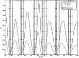
도 5 및 6은 시뮬레이션의 결과를 보이고 있다. 도 5에서, 원래의 CVD는 파선으로 표시하고 시프트 및 확장된 CVD는 실선으로 표시하고 있다. 도 6에서, 상기 시프트 및 확장된 CVD는 파선으로 그리고 m=64일 때의 히스토그램은 실선으로 표시하고 있다. 도 5 및 6에서, 원래 CVD에 적합한 디폴트 판독 기준문턱 전압은 원이 표시된 수직선으로 표시하고, 상기 시프트 및 확장된 CVD에 적합한 최적의 판독 기준문턱 전압은 x's가 표시된 수직선으로 표시하고 있다. 도 6에서, 알고리즘 2에 따라 계산한 판독 기준문턱 전압은 정사각형이 표시된 수직선으로 표시하고, 알고리즘 3에 따라 계산한 판독 기준문턱 전압은 삼각형이 표시된 수직선으로 표시하고 있다.5 and 6 show the results of the simulation. In Figure 5, the original CVD is indicated by broken lines and the shifted and expanded CVD is indicated by solid lines. In FIG. 6, the shifted and expanded CVD is indicated by broken lines and the histogram when m = 64 is indicated by solid lines. 5 and 6, the default read reference threshold voltage suitable for the original CVD is indicated by a vertical line with circles, and the optimal read reference threshold voltage suitable for the shifted and extended CVD is indicated with a vertical line with x's. In FIG. 6, the read reference threshold voltage calculated according to
m≥4l에 대한 100번의 실험결과에 따른 CER을 다음 표에 나타내고 있다.The CERs according to the results of 100 experiments for m≥4l are shown in the following table.

상기 방법론은 이용하여 모든 L 전압 레벨의 강하를 엄격히 추정할 필요는 없다. 적절한 가정하에, 예를 들어 강하


예를 들어, L=16인 경우,


미국 특허 제 6,522,580(첸 외.)의 도 1에서 인용한 도 7은 본 발명의 플래시 메모리 장치의 고수준 블록 다이어그램이다. 매트릭스 형태로 배열된 복수의 메모리 셀(M)을 포함하는 메모리셀 배열(1)은 열 제어회로(2), 행 제어회로(3), c-소스 제어회로(4), 및 c-p-웰 제어회로에 의해 제어된다. 열 제어회로(2)는 메모리셀(M)에 저장된 데이터를 판독하고, 프로그래밍시 메모리셀(M)의 상태를 결정하며, 상기 프로그래밍을 촉진 및 금지시키도록 비트 라인(BL)의 전압 레벨을 제어하기 위해 메모리셀 배열(1)의 상기 비트 라인(BL)에 연결된다. 행 제어회로(3)는 워드라인(WL) 중 하나를 선택하고, 판독 전압을 인가하며, 열 제어회로(2)에 의해 제어되는 비트 라인 전압 레벨과 결합된 프로그래밍 전압을 인가하고, 상기 메모리셀(M)이 형성된 p-형 영역의 전압과 연결된 삭제전압을 인가하기 위해 상기 워드라인(WL)에 연결된다. C-소스 제어회로(4)는 상기 메모리셀(M)에 연결된 공통 소스라인을 제어한다. C-p-웰 제어회로(5)는 c-p-웰 전압을 제어한다. 일반적으로, NAND 플래시 장치에서, 하나의 워드라인에 의해 제어되는 셀은 상기 장치의 하나 또는 두 개이 페이지에 대응된다.Referring to FIG. 1 of US Pat. No. 6,522,580 (Chen et al.), FIG. 7 is a high level block diagram of a flash memory device of the present invention. The
상기 메모리셀(M)에 저장된 데이터는 판독되는 워드라인의 메모리셀의 문턱 전압을 하나 이상의 기준 전압과 비교함으로써 상기 열 제어회로(2)에 의해 판독되고, 또한 I/O 라인 및 데이터 입출력 버퍼(6)를 통해 외부 I/O 라인으로 출력된다. 사기 메모리셀에 저장될 프로그램 데이터는 상기 외부 I/O 라인을 통해 데이터 입출력 버퍼(6)로 입력되어 열 제어회로(2)로 전달된다. 상기 외부 I/O 라인은 제어기(20)에 연결된다.The data stored in the memory cell M is read by the
플래시 메모리 장치를 제어하기 위한 명령데이터는 제어기(20)와 연결된 외부 제어라인에 연결된 명령 인터페이스로 입력된다. 상기 명령데이터는 상기 플래시 메모리에 어떤 작업이 요청되었는지를 알려준다. 상기 입력된 명령은 열 제어회로(2), 행 제어회로(3), c-소스 제어회로(4), c-p-웰 제어회로(5), 및 데이터 입출력 버퍼(6)를 제어하는 상태 기기(8)로 전달된다. 상기 상태 기기(8)는 예를 들어 준비/사용중 또는 통과/실패와 같은 플래시 메모리의 상태 데이터를 출력할 수 있다.Command data for controlling the flash memory device is input to a command interface connected to an external control line connected to the
제어기(20)는 개인 컴퓨터, 디지털 카메라, 개인 디지털 보조기기와 같은 호스트 시스템에 연결되거나 연결될 수 있다. 메모리 배열(1)에 데이터를 기록하거나 이로부터 판독하는 것과 같은 명령을 초기화하고 이런 데이터를 제공하거나 수신하는 것이 호스트이다. 제어기(20)는 이러한 명령을 명령회로(7)에 의해 해석 및 실행될 수 있는 명령신호로 변환한다. 제어기(20)는 또한 일반적으로 메모리 배열(1)에 프로그램되거나 이로부터 판독되는 사용자 데이터용 버퍼 메모리를 포함한다. 일반적인 메모리 시스템은 제어기(20)를 포함하는 하나의 집적회로칩(21) 및, 메모리 배열 및 관련제어, 입출력 및 상태 기기회로를 각각 포함하는 하나 이상의 집적회로칩(22)을 포함한다. 물론, 이러한 추세는 하나 이상의 집적회로 상에 메모리 배열과 시스템의 제어기 회로를 집적하는 것이다. 상기 메모리 시스템은 상기 호스 트 시스템의 일부로서 포함될 수 있고, 또는 호스트 시스템의 상대소켓에 제거가능하게 삽입될 수 있는 메모리 카드에 포함될 수도 있다. 이러한 카드는 관련 주변회로와 함께 전체 메모리 시스템, 또는 제어기 및 메모리 배열을 포함할 수 있고, 분리된 카드의 형태로 제공될 수도 있다.The
제어기(20)는 또한 본 발명의 하나 이상의 방법을 이용하여 회로칩(21) 상의 회로에 의해 저장된 데이터의 판독을 다듬게 되는데, 상기 방법은 문턱 전압 빈에 따라 및/또는 셀을 재판독하지 않고 판독 셀의 상태 할당을 보정하기 위해 히스토그램을 이용하여 하나 이상의 기준 전압을 선택하는 단계를 포함한다.The
도 8은 본 발명의 시스템(30)의 고수준 블록 다이어그램이다. 시스템(30)은 프로세서(32)와 네 개의 메모리 장치, 즉 RAM(34), 부팅 ROM(36), 대용량 저장장치(하드디스크)(38), 및 플래시 메모리 장치(42)를 포함하고, 상기 메모리 장치는 모두 공통버스(60)를 통해 통신한다. 플래시 메모리 장치(42)는, 제어기(20)의 기능성이 대용량 저장장치(38)에 저장되어 프로세서(32)에 의해 실행되는 플래시 메모리 드라이버 코드(40)에 의해 대행되는 상태에서, 회로칩(21) 상에 제작된, 도 7에 도시한 플래시 메모리 장치의 일부와 실질적으로 동일하다. 드리이버 코드(40)는 프로세서(32)에 의해 실행되는 사용자 응용프로그램과 플래시 메모리 장치(42) 사이에 접속된다. 드리이버 코드(40)는 일반적으로 시스템(30)의 시스템코드의 작동시 포함되지만, 프리스탠딩 코드일 수 있다.8 is a high level block diagram of a system 30 of the present invention. System 30 includes a
플래시 메모리 장치(42) 이외의 상기 시스템(30)의 구성요소는 플래시 메모리 장치(42)의 호스트(50)를 구성한다. 대용량 저장장치(38)는 본 발명을 구현하기 위한 컴퓨터에 의해 판독 가능한 드라이버 코드를 갖는 컴퓨터에 의해 판독 가능한 저장 매체의 한 예이다. 상기 컴퓨터에 의해 판독 가능한 저장 매체의 다른 예로는 상기 코드를 포함하는 CD와 같이 읽기만 가능한 메모리가 있다.Components of the system 30 other than the
일정 수의 실시예를 참고로 본 발명을 설명하였지만, 본 발명의 다양한 변형, 변경, 및 기타 적용이 가능하다.Although the present invention has been described with reference to a number of embodiments, various modifications, changes, and other applications of the present invention are possible.
상술한 바와 같이, 본 발명은, 셀당 다중 비트 플래시 메모리에 대한 판독 기준 전압을 최적화시키는 방법을 제공하는데 사용된다.As noted above, the present invention is used to provide a method of optimizing read reference voltage for a multi-bit flash memory per cell.
Claims (41)
Translated fromKoreanApplications Claiming Priority (5)
| Application Number | Priority Date | Filing Date | Title |
|---|---|---|---|
| US91329907P | 2007-04-23 | 2007-04-23 | |
| US60/913,299 | 2007-04-23 | ||
| US11/941,946 | 2007-11-18 | ||
| US11/941,946US7876621B2 (en) | 2007-04-23 | 2007-11-18 | Adaptive dynamic reading of flash memories |
| PCT/IL2008/000507WO2008129534A1 (en) | 2007-04-23 | 2008-04-14 | Adaptive dynamic reading of flash memories |
Publications (2)
| Publication Number | Publication Date |
|---|---|
| KR20100021999Atrue KR20100021999A (en) | 2010-02-26 |
| KR101423962B1 KR101423962B1 (en) | 2014-08-13 |
Family
ID=39873376
Family Applications (2)
| Application Number | Title | Priority Date | Filing Date |
|---|---|---|---|
| KR1020097020373AExpired - Fee RelatedKR101452774B1 (en) | 2007-04-23 | 2008-04-13 | Adaptive dynamic reading of flash memory |
| KR1020097022802AExpired - Fee RelatedKR101423962B1 (en) | 2007-04-23 | 2008-04-14 | Adaptive dynamic reading of flash memory |
Family Applications Before (1)
| Application Number | Title | Priority Date | Filing Date |
|---|---|---|---|
| KR1020097020373AExpired - Fee RelatedKR101452774B1 (en) | 2007-04-23 | 2008-04-13 | Adaptive dynamic reading of flash memory |
Country Status (4)
| Country | Link |
|---|---|
| US (4) | US7903468B2 (en) |
| KR (2) | KR101452774B1 (en) |
| TW (2) | TWI378455B (en) |
| WO (2) | WO2008129533A1 (en) |
Cited By (1)
| Publication number | Priority date | Publication date | Assignee | Title |
|---|---|---|---|---|
| KR20200024355A (en)* | 2017-08-31 | 2020-03-06 | 마이크론 테크놀로지, 인크. | Determining the Data State of a Memory Cell |
Families Citing this family (145)
| Publication number | Priority date | Publication date | Assignee | Title |
|---|---|---|---|---|
| US11244727B2 (en) | 2006-11-29 | 2022-02-08 | Rambus Inc. | Dynamic memory rank configuration |
| US8344475B2 (en) | 2006-11-29 | 2013-01-01 | Rambus Inc. | Integrated circuit heating to effect in-situ annealing |
| WO2008067494A1 (en)* | 2006-11-29 | 2008-06-05 | Rambus Inc. | Integrated circuit with built-in heating circuitry to reverse operational degeneration |
| US8019938B2 (en) | 2006-12-06 | 2011-09-13 | Fusion-I0, Inc. | Apparatus, system, and method for solid-state storage as cache for high-capacity, non-volatile storage |
| US7903468B2 (en)* | 2007-04-23 | 2011-03-08 | Ramot At Telaviv University Ltd. | Adaptive dynamic reading of flash memories |
| WO2008139441A2 (en)* | 2007-05-12 | 2008-11-20 | Anobit Technologies Ltd. | Memory device with internal signal processing unit |
| US7966547B2 (en)* | 2007-07-02 | 2011-06-21 | International Business Machines Corporation | Multi-bit error correction scheme in multi-level memory storage system |
| US8193573B2 (en)* | 2007-09-05 | 2012-06-05 | Rambus Inc. | Repairing defects in a nonvolatile semiconductor memory device utilizing a heating element |
| US7808819B2 (en) | 2008-04-29 | 2010-10-05 | Sandisk Il Ltd. | Method for adaptive setting of state voltage levels in non-volatile memory |
| US7957187B2 (en)* | 2008-05-09 | 2011-06-07 | Sandisk Corporation | Dynamic and adaptive optimization of read compare levels based on memory cell threshold voltage distribution |
| KR101518199B1 (en)* | 2008-05-23 | 2015-05-06 | 삼성전자주식회사 | An error correction device, a method thereof, and a memory device including the device |
| US8458563B2 (en)* | 2008-06-23 | 2013-06-04 | Ramot At Tel Aviv University Ltd. | Reading a flash memory by joint decoding and cell voltage distribution tracking |
| US8464131B2 (en)* | 2008-06-23 | 2013-06-11 | Ramot At Tel Aviv University Ltd. | Reading a flash memory by constrained decoding |
| US7808831B2 (en)* | 2008-06-30 | 2010-10-05 | Sandisk Corporation | Read disturb mitigation in non-volatile memory |
| US8458536B2 (en)* | 2008-07-17 | 2013-06-04 | Marvell World Trade Ltd. | Data recovery in solid state memory devices |
| US8291297B2 (en)* | 2008-12-18 | 2012-10-16 | Intel Corporation | Data error recovery in non-volatile memory |
| US8374026B2 (en)* | 2009-01-30 | 2013-02-12 | Sandisk Il Ltd. | System and method of reading data using a reliability measure |
| US7995387B2 (en)* | 2009-01-30 | 2011-08-09 | Sandisk Il Ltd. | System and method to read data subject to a disturb condition |
| US20100220514A1 (en)* | 2009-03-02 | 2010-09-02 | Lyric Semiconductor, Inc. | Storage devices with soft processing |
| US8458114B2 (en)* | 2009-03-02 | 2013-06-04 | Analog Devices, Inc. | Analog computation using numerical representations with uncertainty |
| US8266503B2 (en) | 2009-03-13 | 2012-09-11 | Fusion-Io | Apparatus, system, and method for using multi-level cell storage in a single-level cell mode |
| US8107306B2 (en) | 2009-03-27 | 2012-01-31 | Analog Devices, Inc. | Storage devices with soft processing |
| US7848152B1 (en)* | 2009-05-12 | 2010-12-07 | Skymedi Corporation | Method and system for adaptively finding reference voltages for reading data from a MLC flash memory |
| US7907445B2 (en)* | 2009-06-17 | 2011-03-15 | Skymedi Corporation | Method and system for obtaining a reference block for a MLC flash memory |
| US8386856B2 (en) | 2009-07-01 | 2013-02-26 | Silicon Motion, Inc. | Data storage device capable of selecting scrambled signals according to transmission power |
| JP5361603B2 (en) | 2009-08-13 | 2013-12-04 | 株式会社東芝 | controller |
| US8072805B2 (en)* | 2009-08-18 | 2011-12-06 | Skymedi Corporation | Method and system of finding a read voltage for a flash memory |
| CN102576569A (en)* | 2009-08-21 | 2012-07-11 | 拉姆伯斯公司 | In-situ memory annealing |
| CN102473460B (en)* | 2009-08-25 | 2016-10-12 | 桑迪士克以色列有限公司 | Restoring data to flash memory devices |
| EP2473999A1 (en) | 2009-08-31 | 2012-07-11 | SanDisk IL Ltd. | Preloading data into a flash storage device |
| US9223514B2 (en) | 2009-09-09 | 2015-12-29 | SanDisk Technologies, Inc. | Erase suspend/resume for memory |
| US8437183B2 (en)* | 2009-12-16 | 2013-05-07 | Sandisk Il Ltd. | Auxiliary parity bits for data written in multi-level cells |
| US8854882B2 (en) | 2010-01-27 | 2014-10-07 | Intelligent Intellectual Property Holdings 2 Llc | Configuring storage cells |
| US8380915B2 (en) | 2010-01-27 | 2013-02-19 | Fusion-Io, Inc. | Apparatus, system, and method for managing solid-state storage media |
| US8315092B2 (en)* | 2010-01-27 | 2012-11-20 | Fusion-Io, Inc. | Apparatus, system, and method for determining a read voltage threshold for solid-state storage media |
| US8661184B2 (en) | 2010-01-27 | 2014-02-25 | Fusion-Io, Inc. | Managing non-volatile media |
| US9245653B2 (en) | 2010-03-15 | 2016-01-26 | Intelligent Intellectual Property Holdings 2 Llc | Reduced level cell mode for non-volatile memory |
| US8233324B2 (en)* | 2010-03-25 | 2012-07-31 | Sandisk Il Ltd. | Simultaneous multi-state read or verify in non-volatile storage |
| US8576625B1 (en)* | 2010-04-20 | 2013-11-05 | Marvell International Ltd. | Decoder parameter estimation using multiple memory reads |
| KR20110128436A (en) | 2010-05-24 | 2011-11-30 | 삼성전자주식회사 | A read level estimating method of a nonvolatile memory device, a memory controller performing the same, and a recording medium |
| JP5596143B2 (en)* | 2010-06-29 | 2014-09-24 | パナソニック株式会社 | Nonvolatile memory system, power supply circuit for memory system, flash memory, flash memory controller, and nonvolatile semiconductor memory device |
| US8984216B2 (en) | 2010-09-09 | 2015-03-17 | Fusion-Io, Llc | Apparatus, system, and method for managing lifetime of a storage device |
| US9047178B2 (en) | 2010-12-13 | 2015-06-02 | SanDisk Technologies, Inc. | Auto-commit memory synchronization |
| CN103262054B (en) | 2010-12-13 | 2015-11-25 | 桑迪士克科技股份有限公司 | For automatically submitting device, the system and method for storer to |
| US9208071B2 (en) | 2010-12-13 | 2015-12-08 | SanDisk Technologies, Inc. | Apparatus, system, and method for accessing memory |
| US9218278B2 (en) | 2010-12-13 | 2015-12-22 | SanDisk Technologies, Inc. | Auto-commit memory |
| US10817421B2 (en) | 2010-12-13 | 2020-10-27 | Sandisk Technologies Llc | Persistent data structures |
| US10817502B2 (en) | 2010-12-13 | 2020-10-27 | Sandisk Technologies Llc | Persistent memory management |
| US8665650B2 (en) | 2011-02-18 | 2014-03-04 | Marvell World Trade Ltd. | Reliability metrics management for soft decoding |
| KR101818504B1 (en) | 2011-02-24 | 2018-01-15 | 삼성전자 주식회사 | Semiconductor memory device and semiconductor memory system |
| US8631288B2 (en) | 2011-03-14 | 2014-01-14 | Micron Technology, Inc. | Methods, devices, and systems for data sensing in a memory system |
| US9324433B2 (en) | 2011-04-25 | 2016-04-26 | Microsoft Technology Licensing, Llc | Intelligent flash reprogramming |
| US8406053B1 (en) | 2011-09-21 | 2013-03-26 | Sandisk Technologies Inc. | On chip dynamic read for non-volatile storage |
| US8760932B2 (en) | 2011-10-18 | 2014-06-24 | Seagate Technology Llc | Determination of memory read reference and programming voltages |
| US8711619B2 (en) | 2011-10-18 | 2014-04-29 | Seagate Technology Llc | Categorizing bit errors of solid-state, non-volatile memory |
| US8693257B2 (en) | 2011-10-18 | 2014-04-08 | Seagate Technology Llc | Determining optimal read reference and programming voltages for non-volatile memory using mutual information |
| US8737133B2 (en) | 2011-10-18 | 2014-05-27 | Seagate Technology Llc | Shifting cell voltage based on grouping of solid-state, non-volatile memory cells |
| US8683297B2 (en)* | 2011-11-02 | 2014-03-25 | Sandisk Technologies Inc. | Systems and methods of generating a replacement default read threshold |
| US8687421B2 (en) | 2011-11-21 | 2014-04-01 | Sandisk Technologies Inc. | Scrub techniques for use with dynamic read |
| US8644067B2 (en) | 2011-11-30 | 2014-02-04 | Sandisk Technologies Inc. | Systems and methods of decoding data using soft bits at a non-binary decoder that uses probabilistic decoding |
| GB201203496D0 (en) | 2012-02-29 | 2012-04-11 | Ibm | Read-detection in solid-state storage devices |
| US8838881B2 (en) | 2012-03-01 | 2014-09-16 | Seagate Technology Llc | Transfer command with specified sense threshold vector component |
| US8934306B2 (en)* | 2012-03-06 | 2015-01-13 | Micron Technology, Inc. | Memory and sense parameter determination methods |
| US8839073B2 (en) | 2012-05-04 | 2014-09-16 | Lsi Corporation | Zero-one balance management in a solid-state disk controller |
| US20130343131A1 (en)* | 2012-06-26 | 2013-12-26 | Lsi Corporation | Fast tracking for flash channels |
| US8605502B1 (en) | 2012-05-22 | 2013-12-10 | Sandisk Technologies Inc. | Systems and methods of updating read voltages |
| US9135106B2 (en)* | 2012-05-22 | 2015-09-15 | Hgst Technologies Santa Ana, Inc. | Read level adjustment using soft information |
| US8811076B2 (en) | 2012-07-30 | 2014-08-19 | Sandisk Technologies Inc. | Systems and methods of updating read voltages |
| US8792281B2 (en) | 2012-08-21 | 2014-07-29 | Apple Inc. | Read threshold estimation in analog memory cells using simultaneous multi-voltage sense |
| US8874992B2 (en) | 2012-08-31 | 2014-10-28 | Sandisk Technologies Inc. | Systems and methods to initiate updating of reference voltages |
| US8848453B2 (en)* | 2012-08-31 | 2014-09-30 | Micron Technology, Inc. | Inferring threshold voltage distributions associated with memory cells via interpolation |
| US9036417B2 (en) | 2012-09-06 | 2015-05-19 | Sandisk Technologies Inc. | On chip dynamic read level scan and error detection for nonvolatile storage |
| US9349489B2 (en) | 2013-01-11 | 2016-05-24 | Sandisk Technologies Inc. | Systems and methods to update reference voltages in response to data retention in non-volatile memory |
| US9076545B2 (en) | 2013-01-17 | 2015-07-07 | Sandisk Tecnologies Inc. | Dynamic adjustment of read voltage levels based on memory cell threshold voltage distribution |
| US9070479B2 (en) | 2013-01-21 | 2015-06-30 | Sandisk Technologies Inc. | Systems and methods of updating read voltages |
| US9318215B2 (en) | 2013-02-14 | 2016-04-19 | Sandisk Technologies Inc. | Systems and methods to update reference voltages of non-volatile memory |
| US10230396B1 (en) | 2013-03-05 | 2019-03-12 | Microsemi Solutions (Us), Inc. | Method and apparatus for layer-specific LDPC decoding |
| US9813080B1 (en) | 2013-03-05 | 2017-11-07 | Microsemi Solutions (U.S.), Inc. | Layer specific LDPC decoder |
| US9135109B2 (en) | 2013-03-11 | 2015-09-15 | Seagate Technology Llc | Determination of optimum threshold voltage to read data values in memory cells |
| US9530515B2 (en) | 2013-03-13 | 2016-12-27 | Sandisk Technologies Llc | Determining read voltages for reading memory |
| US9147490B2 (en)* | 2013-03-15 | 2015-09-29 | Sandisk Technologies Inc. | System and method of determining reading voltages of a data storage device |
| US9122626B2 (en) | 2013-05-13 | 2015-09-01 | Seagate Technology Llc | Linearly related threshold voltage offsets |
| US8971111B2 (en) | 2013-05-23 | 2015-03-03 | Seagate Technology Llc | Threshold voltage calibration using reference pattern detection |
| US10475523B2 (en) | 2013-05-31 | 2019-11-12 | Western Digital Technologies, Inc. | Updating read voltages triggered by the rate of temperature change |
| US9728263B2 (en) | 2013-05-31 | 2017-08-08 | Sandisk Technologies Llc | Method and device for iteratively updating read voltages |
| US9697905B2 (en) | 2013-05-31 | 2017-07-04 | Sandisk Technologies Llc | Updating read voltages using syndrome weight comparisons |
| CN104240761B (en)* | 2013-06-08 | 2017-07-14 | 光宝科技股份有限公司 | Method for estimating distribution curve of storage state in solid-state storage device |
| US10083069B2 (en) | 2013-06-27 | 2018-09-25 | Sandisk Technologies Llc | Word line defect detection and handling for a data storage device |
| US10319460B2 (en)* | 2013-08-14 | 2019-06-11 | Infineon Technologies Ag | Systems and methods utilizing a flexible read reference for a dynamic read window |
| KR102120823B1 (en) | 2013-08-14 | 2020-06-09 | 삼성전자주식회사 | Method of controlling read sequence of nov-volatile memory device and memory system performing the same |
| US9213599B2 (en) | 2013-09-18 | 2015-12-15 | Seagate Technology Llc | Method of erase state handling in flash channel tracking |
| US9036413B2 (en) | 2013-09-27 | 2015-05-19 | Seagate Technology Llc | Flash memory reference voltage detection with tracking of cross-points of cell voltage distributions using histograms |
| US8953373B1 (en) | 2013-10-03 | 2015-02-10 | Lsi Corporation | Flash memory read retry using histograms |
| GB2520708A (en) | 2013-11-28 | 2015-06-03 | Ibm | Multi-stage codeword detector |
| US20150205664A1 (en)* | 2014-01-17 | 2015-07-23 | Fusion-Io, Inc. | Determining a configuration parameter using a soft read command |
| US20150294739A1 (en)* | 2014-04-10 | 2015-10-15 | Lsi Corporation | Online histogram and soft information learning |
| KR102174030B1 (en) | 2014-05-13 | 2020-11-05 | 삼성전자주식회사 | Storage device including nonvolatile memory device and read method thereof |
| US10795765B2 (en) | 2014-07-22 | 2020-10-06 | Ngd Systems, Inc. | SSD for long term data retention |
| US10417087B2 (en)* | 2014-07-22 | 2019-09-17 | Ngd Systems, Inc. | System and method for adaptive multiple read of NAND flash |
| CN105468471A (en)* | 2014-09-12 | 2016-04-06 | 光宝科技股份有限公司 | Solid-state storage device and error correction method thereof |
| US9406377B2 (en) | 2014-12-08 | 2016-08-02 | Sandisk Technologies Llc | Rewritable multibit non-volatile memory with soft decode optimization |
| KR102292643B1 (en) | 2015-02-17 | 2021-08-23 | 삼성전자주식회사 | Resistive Memory Device, Resistive Memory System and Operating Method thereof |
| KR102284658B1 (en) | 2015-03-19 | 2021-08-02 | 삼성전자 주식회사 | Non-volatile memory device, Memory system including the same, and Method of operating the same |
| US9472298B1 (en) | 2015-05-13 | 2016-10-18 | Sandisk Technologies Llc | Dynamic read valley search in non-volatile memory |
| US10332613B1 (en) | 2015-05-18 | 2019-06-25 | Microsemi Solutions (Us), Inc. | Nonvolatile memory system with retention monitor |
| US9799405B1 (en) | 2015-07-29 | 2017-10-24 | Ip Gem Group, Llc | Nonvolatile memory system with read circuit for performing reads using threshold voltage shift read instruction |
| US9875803B2 (en) | 2015-09-10 | 2018-01-23 | Toshiba Memory Corporation | Memory system and method of controlling nonvolatile memory |
| US10347343B2 (en)* | 2015-10-30 | 2019-07-09 | Seagate Technology Llc | Adaptive read threshold voltage tracking with separate characterization on each side of voltage distribution about distribution mean |
| KR102412781B1 (en) | 2015-11-03 | 2022-06-24 | 삼성전자주식회사 | Non-volatile memory device and method of reading non-volatile memory device |
| KR20170058066A (en)* | 2015-11-18 | 2017-05-26 | 에스케이하이닉스 주식회사 | Data storage device and operating method thereof |
| US9886214B2 (en) | 2015-12-11 | 2018-02-06 | Ip Gem Group, Llc | Nonvolatile memory system with erase suspend circuit and method for erase suspend management |
| US9892794B2 (en) | 2016-01-04 | 2018-02-13 | Ip Gem Group, Llc | Method and apparatus with program suspend using test mode |
| US9899092B2 (en) | 2016-01-27 | 2018-02-20 | Ip Gem Group, Llc | Nonvolatile memory system with program step manager and method for program step management |
| US9679661B1 (en) | 2016-06-28 | 2017-06-13 | Sandisk Technologies Llc | Non-volatile storage system with self-test for read performance enhancement feature setup |
| US10157677B2 (en) | 2016-07-28 | 2018-12-18 | Ip Gem Group, Llc | Background reference positioning and local reference positioning using threshold voltage shift read |
| US10291263B2 (en) | 2016-07-28 | 2019-05-14 | Ip Gem Group, Llc | Auto-learning log likelihood ratio |
| US10236915B2 (en) | 2016-07-29 | 2019-03-19 | Microsemi Solutions (U.S.), Inc. | Variable T BCH encoding |
| US10262744B2 (en) | 2016-08-11 | 2019-04-16 | SK Hynix Inc. | Layer-based memory controller optimizations for three dimensional memory constructs |
| US9672940B1 (en) | 2016-08-18 | 2017-06-06 | Sandisk Technologies Llc | Non-volatile memory with fast read process |
| US10558381B2 (en)* | 2016-12-16 | 2020-02-11 | Sandisk Technologies Llc | Dynamic read table generation |
| KR102695928B1 (en) | 2016-12-19 | 2024-08-16 | 삼성전자주식회사 | Read operation method of nonvoltile memory, memory system including the same and operation method thereof |
| US10381090B2 (en) | 2017-03-31 | 2019-08-13 | Samsung Electronics Co., Ltd. | Operation method of nonvolatile memory device and storage device |
| KR102349382B1 (en)* | 2017-10-11 | 2022-01-12 | 에스케이하이닉스 주식회사 | Memory system and operating method thereof |
| KR102395196B1 (en) | 2017-10-17 | 2022-05-06 | 삼성전자주식회사 | Storage device having parameter calibration function and method of operating the storage device |
| US10276233B1 (en) | 2017-10-31 | 2019-04-30 | Seagate Technology Llc | Adaptive read threshold voltage tracking with charge leakage mitigation using threshold voltage offsets |
| US10388368B2 (en) | 2017-10-31 | 2019-08-20 | Seagate Technology Llc | Adaptive read threshold voltage tracking with charge leakage mitigation using charge leakage settling time |
| US10418097B2 (en) | 2017-11-27 | 2019-09-17 | Western Digital Technologies, Inc. | Non-volatile storage system with read calibration |
| KR102470726B1 (en) | 2018-03-14 | 2022-11-25 | 삼성전자주식회사 | Non-volatile memory device |
| KR102617350B1 (en)* | 2018-03-14 | 2023-12-26 | 삼성전자주식회사 | Memory controller, operating method thereof and storage device including the same |
| JP2019164850A (en)* | 2018-03-19 | 2019-09-26 | 東芝メモリ株式会社 | Memory system |
| TWI649754B (en)* | 2018-04-16 | 2019-02-01 | 群聯電子股份有限公司 | Memory management method, memory storage device, and memory control circuit unit |
| US10990295B2 (en)* | 2018-06-14 | 2021-04-27 | Western Digital Technologies, Inc. | Write level optimization for non-volatile memory |
| US10811091B2 (en) | 2018-10-12 | 2020-10-20 | Western Digital Technologies, Inc. | Adaptive processing for read threshold voltage calibration |
| US11163483B2 (en)* | 2018-12-31 | 2021-11-02 | SK Hynix Inc. | Robust detection techniques for updating read voltages of memory devices |
| US10872671B1 (en) | 2019-06-13 | 2020-12-22 | Sandisk Technologies Llc | Dynamic read voltages in non-volatile memory |
| US11487548B2 (en) | 2019-11-26 | 2022-11-01 | Sandisk Technologies Llc | Dynamic re-evaluation of parameters for non-volatile memory using microcontroller |
| KR102736243B1 (en) | 2020-01-02 | 2024-12-02 | 에스케이하이닉스 주식회사 | Memory system and operating method thereof |
| KR20210128704A (en)* | 2020-04-17 | 2021-10-27 | 에스케이하이닉스 주식회사 | Controller and operation method thereof |
| US11289172B2 (en) | 2020-08-13 | 2022-03-29 | Western Digital Technologies, Inc. | Soft bit reference level calibration |
| US11322214B1 (en) | 2021-01-13 | 2022-05-03 | SK Hynix Inc. | Gaussian modeling for soft-read threshold estimation in non-volatile memory devices |
| US11538534B1 (en) | 2021-06-08 | 2022-12-27 | Western Digital Technologies, Inc. | Soft bit reference level calibration using decoded data |
| KR102615133B1 (en)* | 2021-06-30 | 2023-12-19 | (주)브릭 | Method and apparatus for transforming data distribution |
| US12148496B2 (en) | 2022-06-29 | 2024-11-19 | Apple Inc. | Readout from memory cells subjected to perturbations in threshold voltage distributions |
| JP7495635B2 (en) | 2022-10-12 | 2024-06-05 | 東芝情報システム株式会社 | Debugging device and debugging program |
| KR20240177463A (en) | 2023-06-20 | 2024-12-27 | 삼성전자주식회사 | Storage device, and opertaing method of memory controller |
Family Cites Families (19)
| Publication number | Priority date | Publication date | Assignee | Title |
|---|---|---|---|---|
| US5657332A (en)* | 1992-05-20 | 1997-08-12 | Sandisk Corporation | Soft errors handling in EEPROM devices |
| US6269023B1 (en)* | 2000-05-19 | 2001-07-31 | Advanced Micro Devices, Inc. | Method of programming a non-volatile memory cell using a current limiter |
| US6522580B2 (en) | 2001-06-27 | 2003-02-18 | Sandisk Corporation | Operating techniques for reducing effects of coupling between storage elements of a non-volatile memory operated in multiple data states |
| US6751766B2 (en)* | 2002-05-20 | 2004-06-15 | Sandisk Corporation | Increasing the effectiveness of error correction codes and operating multi-level memory systems by using information about the quality of the stored data |
| US6963505B2 (en) | 2002-10-29 | 2005-11-08 | Aifun Semiconductors Ltd. | Method circuit and system for determining a reference voltage |
| US7957189B2 (en) | 2004-07-26 | 2011-06-07 | Sandisk Il Ltd. | Drift compensation in a flash memory |
| US7817469B2 (en) | 2004-07-26 | 2010-10-19 | Sandisk Il Ltd. | Drift compensation in a flash memory |
| US7257025B2 (en)* | 2004-12-09 | 2007-08-14 | Saifun Semiconductors Ltd | Method for reading non-volatile memory cells |
| JP2007012180A (en)* | 2005-06-30 | 2007-01-18 | Renesas Technology Corp | Semiconductor memory device |
| US7954037B2 (en) | 2005-10-25 | 2011-05-31 | Sandisk Il Ltd | Method for recovering from errors in flash memory |
| KR100724339B1 (en)* | 2006-01-25 | 2007-06-04 | 삼성전자주식회사 | A three-level nonvolatile semiconductor memory device having a fast first page read speed and a driving method thereof |
| US7613043B2 (en)* | 2006-05-15 | 2009-11-03 | Apple Inc. | Shifting reference values to account for voltage sag |
| JP2008047273A (en)* | 2006-07-20 | 2008-02-28 | Toshiba Corp | Semiconductor memory device and control method thereof |
| US7716538B2 (en) | 2006-09-27 | 2010-05-11 | Sandisk Corporation | Memory with cell population distribution assisted read margining |
| US7886204B2 (en) | 2006-09-27 | 2011-02-08 | Sandisk Corporation | Methods of cell population distribution assisted read margining |
| US8127200B2 (en)* | 2006-12-24 | 2012-02-28 | Sandisk Il Ltd. | Flash memory device and system with randomizing for suppressing errors |
| US8369141B2 (en) | 2007-03-12 | 2013-02-05 | Apple Inc. | Adaptive estimation of memory cell read thresholds |
| US20080263256A1 (en) | 2007-04-20 | 2008-10-23 | Motorola, Inc. | Logic Device with Write Protected Memory Management Unit Registers |
| US7903468B2 (en) | 2007-04-23 | 2011-03-08 | Ramot At Telaviv University Ltd. | Adaptive dynamic reading of flash memories |
- 2007
- 2007-11-18USUS11/941,945patent/US7903468B2/ennot_activeExpired - Fee Related
- 2007-11-18USUS11/941,946patent/US7876621B2/enactiveActive
- 2008
- 2008-04-13KRKR1020097020373Apatent/KR101452774B1/ennot_activeExpired - Fee Related
- 2008-04-13WOPCT/IL2008/000506patent/WO2008129533A1/enactiveApplication Filing
- 2008-04-14KRKR1020097022802Apatent/KR101423962B1/ennot_activeExpired - Fee Related
- 2008-04-14WOPCT/IL2008/000507patent/WO2008129534A1/enactiveApplication Filing
- 2008-04-22TWTW097114670Apatent/TWI378455B/ennot_activeIP Right Cessation
- 2008-04-23TWTW097114920Apatent/TWI375228B/ennot_activeIP Right Cessation
- 2010
- 2010-12-09USUS12/964,286patent/US8125833B2/enactiveActive
- 2011
- 2011-02-20USUS13/031,221patent/US8289781B2/ennot_activeExpired - Fee Related
Cited By (1)
| Publication number | Priority date | Publication date | Assignee | Title |
|---|---|---|---|---|
| KR20200024355A (en)* | 2017-08-31 | 2020-03-06 | 마이크론 테크놀로지, 인크. | Determining the Data State of a Memory Cell |
Also Published As
| Publication number | Publication date |
|---|---|
| US8125833B2 (en) | 2012-02-28 |
| KR20100014676A (en) | 2010-02-10 |
| KR101452774B1 (en) | 2014-10-21 |
| US7903468B2 (en) | 2011-03-08 |
| TWI378455B (en) | 2012-12-01 |
| TWI375228B (en) | 2012-10-21 |
| US7876621B2 (en) | 2011-01-25 |
| US20110134692A1 (en) | 2011-06-09 |
| US20110182118A1 (en) | 2011-07-28 |
| KR101423962B1 (en) | 2014-08-13 |
| US8289781B2 (en) | 2012-10-16 |
| WO2008129534A1 (en) | 2008-10-30 |
| US20080263266A1 (en) | 2008-10-23 |
| TW200907985A (en) | 2009-02-16 |
| TW200901200A (en) | 2009-01-01 |
| WO2008129533A1 (en) | 2008-10-30 |
| US20080263265A1 (en) | 2008-10-23 |
Similar Documents
| Publication | Publication Date | Title |
|---|---|---|
| KR101423962B1 (en) | Adaptive dynamic reading of flash memory | |
| US7983082B2 (en) | Apparatus and method of multi-bit programming | |
| KR101671313B1 (en) | Methods and apparatus for read-side intercell interference mitigation in flash memories | |
| US9153336B1 (en) | Decoder parameter estimation using multiple memory reads | |
| US7468920B2 (en) | Applying adaptive body bias to non-volatile storage | |
| JP5475665B2 (en) | Flash memory cross-coupling post-correction | |
| US12009034B2 (en) | Classification of error rate of data retrieved from memory cells | |
| US20130339586A1 (en) | Methods for adaptively programming flash memory devices and flash memory systems incorporating same | |
| CN110832593A (en) | Memory device with dynamic processing level calibration | |
| KR101785007B1 (en) | Data storage system having multi-bit memory device and on-chip buffer program method thereof | |
| KR20130023102A (en) | Memory device with reduced sense time readout | |
| JP2006527901A (en) | Reliability enhancement method for flash memory | |
| KR20040074979A (en) | Error management for writable tracking storage units | |
| US20170148525A1 (en) | Method and System For Adaptively Adjusting a Verify Voltage to Reduce Storage Raw Bit Error Rate | |
| JP2007512639A (en) | Method, circuit and system for determining a reference voltage | |
| US7525843B2 (en) | Non-volatile storage with adaptive body bias | |
| KR101558144B1 (en) | Nonvolatile memory and method for correlated multiple pass programming | |
| US20250087288A1 (en) | Adaptive dsp generation of read thresholds for gaussian and non-gaussian distributions in solid state storage using cumulative observed counts | |
| US9053804B2 (en) | Reduced complexity reliability computations for flash memories | |
| CN112435707A (en) | Adaptive application of voltage pulses to stabilize memory cell voltage levels |
Legal Events
| Date | Code | Title | Description |
|---|---|---|---|
| PA0105 | International application | St.27 status event code:A-0-1-A10-A15-nap-PA0105 | |
| P11-X000 | Amendment of application requested | St.27 status event code:A-2-2-P10-P11-nap-X000 | |
| P13-X000 | Application amended | St.27 status event code:A-2-2-P10-P13-nap-X000 | |
| PG1501 | Laying open of application | St.27 status event code:A-1-1-Q10-Q12-nap-PG1501 | |
| A201 | Request for examination | ||
| A302 | Request for accelerated examination | ||
| P11-X000 | Amendment of application requested | St.27 status event code:A-2-2-P10-P11-nap-X000 | |
| P13-X000 | Application amended | St.27 status event code:A-2-2-P10-P13-nap-X000 | |
| PA0201 | Request for examination | St.27 status event code:A-1-2-D10-D11-exm-PA0201 | |
| PA0302 | Request for accelerated examination | St.27 status event code:A-1-2-D10-D17-exm-PA0302 St.27 status event code:A-1-2-D10-D16-exm-PA0302 | |
| R17-X000 | Change to representative recorded | St.27 status event code:A-3-3-R10-R17-oth-X000 | |
| P11-X000 | Amendment of application requested | St.27 status event code:A-2-2-P10-P11-nap-X000 | |
| P13-X000 | Application amended | St.27 status event code:A-2-2-P10-P13-nap-X000 | |
| E902 | Notification of reason for refusal | ||
| PE0902 | Notice of grounds for rejection | St.27 status event code:A-1-2-D10-D21-exm-PE0902 | |
| T11-X000 | Administrative time limit extension requested | St.27 status event code:U-3-3-T10-T11-oth-X000 | |
| E13-X000 | Pre-grant limitation requested | St.27 status event code:A-2-3-E10-E13-lim-X000 | |
| P11-X000 | Amendment of application requested | St.27 status event code:A-2-2-P10-P11-nap-X000 | |
| P13-X000 | Application amended | St.27 status event code:A-2-2-P10-P13-nap-X000 | |
| E701 | Decision to grant or registration of patent right | ||
| PE0701 | Decision of registration | St.27 status event code:A-1-2-D10-D22-exm-PE0701 | |
| GRNT | Written decision to grant | ||
| PR0701 | Registration of establishment | St.27 status event code:A-2-4-F10-F11-exm-PR0701 | |
| PR1002 | Payment of registration fee | St.27 status event code:A-2-2-U10-U12-oth-PR1002 Fee payment year number:1 | |
| PG1601 | Publication of registration | St.27 status event code:A-4-4-Q10-Q13-nap-PG1601 | |
| PN2301 | Change of applicant | St.27 status event code:A-5-5-R10-R11-asn-PN2301 | |
| PN2301 | Change of applicant | St.27 status event code:A-5-5-R10-R14-asn-PN2301 | |
| PN2301 | Change of applicant | St.27 status event code:A-5-5-R10-R13-asn-PN2301 St.27 status event code:A-5-5-R10-R11-asn-PN2301 | |
| R17-X000 | Change to representative recorded | St.27 status event code:A-5-5-R10-R17-oth-X000 | |
| R18-X000 | Changes to party contact information recorded | St.27 status event code:A-5-5-R10-R18-oth-X000 | |
| FPAY | Annual fee payment | Payment date:20170616 Year of fee payment:4 | |
| PR1001 | Payment of annual fee | St.27 status event code:A-4-4-U10-U11-oth-PR1001 Fee payment year number:4 | |
| PR1001 | Payment of annual fee | St.27 status event code:A-4-4-U10-U11-oth-PR1001 Fee payment year number:5 | |
| PC1903 | Unpaid annual fee | St.27 status event code:A-4-4-U10-U13-oth-PC1903 Not in force date:20190723 Payment event data comment text:Termination Category : DEFAULT_OF_REGISTRATION_FEE | |
| R18-X000 | Changes to party contact information recorded | St.27 status event code:A-5-5-R10-R18-oth-X000 | |
| PC1903 | Unpaid annual fee | St.27 status event code:N-4-6-H10-H13-oth-PC1903 Ip right cessation event data comment text:Termination Category : DEFAULT_OF_REGISTRATION_FEE Not in force date:20190723 | |
| PN2301 | Change of applicant | St.27 status event code:A-5-5-R10-R13-asn-PN2301 St.27 status event code:A-5-5-R10-R11-asn-PN2301 | |
| R18-X000 | Changes to party contact information recorded | St.27 status event code:A-5-5-R10-R18-oth-X000 |