KR20100017560A - Substrate cleaning techniques employing multi-phase solution - Google Patents
Substrate cleaning techniques employing multi-phase solutionDownload PDFInfo
- Publication number
- KR20100017560A KR20100017560AKR1020097025122AKR20097025122AKR20100017560AKR 20100017560 AKR20100017560 AKR 20100017560AKR 1020097025122 AKR1020097025122 AKR 1020097025122AKR 20097025122 AKR20097025122 AKR 20097025122AKR 20100017560 AKR20100017560 AKR 20100017560A
- Authority
- KR
- South Korea
- Prior art keywords
- solution
- substrate
- flows
- contaminant
- relative motion
- Prior art date
- Legal status (The legal status is an assumption and is not a legal conclusion. Google has not performed a legal analysis and makes no representation as to the accuracy of the status listed.)
- Ceased
Links
- 239000000758substrateSubstances0.000titleclaimsabstractdescription160
- 238000000034methodMethods0.000titleclaimsabstractdescription54
- 238000004140cleaningMethods0.000titleclaimsabstractdescription32
- 230000008878couplingEffects0.000claimsabstractdescription120
- 238000010168coupling processMethods0.000claimsabstractdescription120
- 238000005859coupling reactionMethods0.000claimsabstractdescription120
- 239000000356contaminantSubstances0.000claimsdescription106
- 238000012545processingMethods0.000claimsdescription22
- 238000004891communicationMethods0.000claimsdescription20
- 239000006260foamSubstances0.000claimsdescription11
- 230000005484gravityEffects0.000claimsdescription9
- 238000011049fillingMethods0.000claimsdescription4
- 239000012530fluidSubstances0.000abstractdescription33
- 239000004065semiconductorSubstances0.000abstractdescription4
- 239000011236particulate materialSubstances0.000abstract3
- 238000007654immersionMethods0.000description65
- KFZMGEQAYNKOFK-UHFFFAOYSA-NIsopropanolChemical compoundCC(C)OKFZMGEQAYNKOFK-UHFFFAOYSA-N0.000description57
- 239000000725suspensionSubstances0.000description48
- 239000008367deionised waterSubstances0.000description36
- 239000007788liquidSubstances0.000description29
- 239000007787solidSubstances0.000description19
- 239000000203mixtureSubstances0.000description16
- 238000002791soakingMethods0.000description16
- 230000006870functionEffects0.000description15
- QIQXTHQIDYTFRH-UHFFFAOYSA-Noctadecanoic acidChemical compoundCCCCCCCCCCCCCCCCCC(O)=OQIQXTHQIDYTFRH-UHFFFAOYSA-N0.000description13
- 235000021355Stearic acidNutrition0.000description12
- 239000000463materialSubstances0.000description12
- OQCDKBAXFALNLD-UHFFFAOYSA-Noctadecanoic acidNatural productsCCCCCCCC(C)CCCCCCCCC(O)=OOQCDKBAXFALNLD-UHFFFAOYSA-N0.000description12
- 239000008117stearic acidSubstances0.000description12
- 238000012546transferMethods0.000description12
- 230000008569processEffects0.000description10
- 150000001732carboxylic acid derivativesChemical class0.000description9
- 235000014113dietary fatty acidsNutrition0.000description9
- 229930195729fatty acidNatural products0.000description9
- 239000000194fatty acidSubstances0.000description9
- 239000002245particleSubstances0.000description9
- 150000004665fatty acidsChemical class0.000description8
- 230000007246mechanismEffects0.000description8
- 239000002253acidSubstances0.000description7
- 239000000126substanceSubstances0.000description7
- 239000007789gasSubstances0.000description6
- VHUUQVKOLVNVRT-UHFFFAOYSA-NAmmonium hydroxideChemical class[NH4+].[OH-]VHUUQVKOLVNVRT-UHFFFAOYSA-N0.000description5
- KRHYYFGTRYWZRS-UHFFFAOYSA-NFluoraneChemical compoundFKRHYYFGTRYWZRS-UHFFFAOYSA-N0.000description5
- MHAJPDPJQMAIIY-UHFFFAOYSA-NHydrogen peroxideChemical compoundOOMHAJPDPJQMAIIY-UHFFFAOYSA-N0.000description4
- 239000000908ammonium hydroxideSubstances0.000description4
- 235000011114ammonium hydroxideNutrition0.000description4
- 239000012636effectorSubstances0.000description4
- 230000003993interactionEffects0.000description4
- 239000002904solventSubstances0.000description4
- 235000012431wafersNutrition0.000description4
- UHOVQNZJYSORNB-UHFFFAOYSA-NBenzeneChemical compoundC1=CC=CC=C1UHOVQNZJYSORNB-UHFFFAOYSA-N0.000description3
- OKTJSMMVPCPJKN-UHFFFAOYSA-NCarbonChemical compound[C]OKTJSMMVPCPJKN-UHFFFAOYSA-N0.000description3
- 125000001931aliphatic groupChemical group0.000description3
- 125000003178carboxy groupChemical group[H]OC(*)=O0.000description3
- 150000001735carboxylic acidsChemical class0.000description3
- 238000012412chemical couplingMethods0.000description3
- 150000001875compoundsChemical class0.000description3
- 230000007547defectEffects0.000description3
- -1fluorocarbonsSubstances0.000description3
- 239000001257hydrogenSubstances0.000description3
- 229910052739hydrogenInorganic materials0.000description3
- VLKZOEOYAKHREP-UHFFFAOYSA-Nn-HexaneChemical compoundCCCCCCVLKZOEOYAKHREP-UHFFFAOYSA-N0.000description3
- 239000000047productSubstances0.000description3
- 238000003756stirringMethods0.000description3
- XLYOFNOQVPJJNP-UHFFFAOYSA-NwaterChemical compoundOXLYOFNOQVPJJNP-UHFFFAOYSA-N0.000description3
- YWWVWXASSLXJHU-AATRIKPKSA-N(9E)-tetradecenoic acidChemical compoundCCCC\C=C\CCCCCCCC(O)=OYWWVWXASSLXJHU-AATRIKPKSA-N0.000description2
- LQJBNNIYVWPHFW-UHFFFAOYSA-N20:1omega9c fatty acidNatural productsCCCCCCCCCCC=CCCCCCCCC(O)=OLQJBNNIYVWPHFW-UHFFFAOYSA-N0.000description2
- CSCPPACGZOOCGX-UHFFFAOYSA-NAcetoneChemical compoundCC(C)=OCSCPPACGZOOCGX-UHFFFAOYSA-N0.000description2
- XKRFYHLGVUSROY-UHFFFAOYSA-NArgonChemical compound[Ar]XKRFYHLGVUSROY-UHFFFAOYSA-N0.000description2
- FERIUCNNQQJTOY-UHFFFAOYSA-NButyric acidChemical compoundCCCC(O)=OFERIUCNNQQJTOY-UHFFFAOYSA-N0.000description2
- RTZKZFJDLAIYFH-UHFFFAOYSA-NDiethyl etherChemical groupCCOCCRTZKZFJDLAIYFH-UHFFFAOYSA-N0.000description2
- IMNFDUFMRHMDMM-UHFFFAOYSA-NN-HeptaneChemical compoundCCCCCCCIMNFDUFMRHMDMM-UHFFFAOYSA-N0.000description2
- OFBQJSOFQDEBGM-UHFFFAOYSA-NPentaneChemical compoundCCCCCOFBQJSOFQDEBGM-UHFFFAOYSA-N0.000description2
- 238000007792additionMethods0.000description2
- 239000000654additiveSubstances0.000description2
- 230000002776aggregationEffects0.000description2
- 150000001298alcoholsChemical class0.000description2
- 229940088990ammonium stearateDrugs0.000description2
- YZXBAPSDXZZRGB-DOFZRALJSA-Narachidonic acidChemical compoundCCCCC\C=C/C\C=C/C\C=C/C\C=C/CCCC(O)=OYZXBAPSDXZZRGB-DOFZRALJSA-N0.000description2
- QVGXLLKOCUKJST-UHFFFAOYSA-Natomic oxygenChemical compound[O]QVGXLLKOCUKJST-UHFFFAOYSA-N0.000description2
- JPNZKPRONVOMLL-UHFFFAOYSA-Nazane;octadecanoic acidChemical compound[NH4+].CCCCCCCCCCCCCCCCCC([O-])=OJPNZKPRONVOMLL-UHFFFAOYSA-N0.000description2
- 230000008901benefitEffects0.000description2
- 230000008859changeEffects0.000description2
- 238000000151depositionMethods0.000description2
- 238000009826distributionMethods0.000description2
- UKMSUNONTOPOIO-UHFFFAOYSA-Ndocosanoic acidChemical compoundCCCCCCCCCCCCCCCCCCCCCC(O)=OUKMSUNONTOPOIO-UHFFFAOYSA-N0.000description2
- POULHZVOKOAJMA-UHFFFAOYSA-Ndodecanoic acidChemical compoundCCCCCCCCCCCC(O)=OPOULHZVOKOAJMA-UHFFFAOYSA-N0.000description2
- KEMQGTRYUADPNZ-UHFFFAOYSA-Nheptadecanoic acidChemical compoundCCCCCCCCCCCCCCCCC(O)=OKEMQGTRYUADPNZ-UHFFFAOYSA-N0.000description2
- IPCSVZSSVZVIGE-UHFFFAOYSA-Nhexadecanoic acidChemical compoundCCCCCCCCCCCCCCCC(O)=OIPCSVZSSVZVIGE-UHFFFAOYSA-N0.000description2
- FUZZWVXGSFPDMH-UHFFFAOYSA-Nhexanoic acidChemical compoundCCCCCC(O)=OFUZZWVXGSFPDMH-UHFFFAOYSA-N0.000description2
- 125000004435hydrogen atomChemical class[H]*0.000description2
- 150000002466iminesChemical class0.000description2
- 238000010348incorporationMethods0.000description2
- 239000002480mineral oilSubstances0.000description2
- 239000003607modifierSubstances0.000description2
- BKIMMITUMNQMOS-UHFFFAOYSA-NnonaneChemical compoundCCCCCCCCCBKIMMITUMNQMOS-UHFFFAOYSA-N0.000description2
- WWZKQHOCKIZLMA-UHFFFAOYSA-Noctanoic acidChemical compoundCCCCCCCC(O)=OWWZKQHOCKIZLMA-UHFFFAOYSA-N0.000description2
- 239000001301oxygenSubstances0.000description2
- 229910052760oxygenInorganic materials0.000description2
- SECPZKHBENQXJG-FPLPWBNLSA-Npalmitoleic acidChemical compoundCCCCCC\C=C/CCCCCCCC(O)=OSECPZKHBENQXJG-FPLPWBNLSA-N0.000description2
- IJTNSXPMYKJZPR-UHFFFAOYSA-Nparinaric acidChemical compoundCCC=CC=CC=CC=CCCCCCCCC(O)=OIJTNSXPMYKJZPR-UHFFFAOYSA-N0.000description2
- 230000000704physical effectEffects0.000description2
- 238000000623plasma-assisted chemical vapour depositionMethods0.000description2
- 239000002798polar solventSubstances0.000description2
- 229920000642polymerPolymers0.000description2
- 229920001184polypeptidePolymers0.000description2
- 102000004196processed proteins & peptidesHuman genes0.000description2
- 108090000765processed proteins & peptidesProteins0.000description2
- 230000004044responseEffects0.000description2
- 238000006467substitution reactionMethods0.000description2
- 239000004094surface-active agentSubstances0.000description2
- OYHQOLUKZRVURQ-NTGFUMLPSA-N(9Z,12Z)-9,10,12,13-tetratritiooctadeca-9,12-dienoic acidChemical compoundC(CCCCCCC\C(=C(/C\C(=C(/CCCCC)\[3H])\[3H])\[3H])\[3H])(=O)OOYHQOLUKZRVURQ-NTGFUMLPSA-N0.000description1
- WRIDQFICGBMAFQ-UHFFFAOYSA-N(E)-8-Octadecenoic acidNatural productsCCCCCCCCCC=CCCCCCCC(O)=OWRIDQFICGBMAFQ-UHFFFAOYSA-N0.000description1
- QSBYPNXLFMSGKH-UHFFFAOYSA-N9-HeptadecensaeureNatural productsCCCCCCCC=CCCCCCCCC(O)=OQSBYPNXLFMSGKH-UHFFFAOYSA-N0.000description1
- YWWVWXASSLXJHU-UHFFFAOYSA-N9E-tetradecenoic acidNatural productsCCCCC=CCCCCCCCC(O)=OYWWVWXASSLXJHU-UHFFFAOYSA-N0.000description1
- QGZKDVFQNNGYKY-UHFFFAOYSA-OAmmoniumChemical compound[NH4+]QGZKDVFQNNGYKY-UHFFFAOYSA-O0.000description1
- IJGRMHOSHXDMSA-UHFFFAOYSA-NAtomic nitrogenChemical compoundN#NIJGRMHOSHXDMSA-UHFFFAOYSA-N0.000description1
- 235000021357Behenic acidNutrition0.000description1
- DPUOLQHDNGRHBS-UHFFFAOYSA-NBrassidinsaeureNatural productsCCCCCCCCC=CCCCCCCCCCCCC(O)=ODPUOLQHDNGRHBS-UHFFFAOYSA-N0.000description1
- 239000005635Caprylic acid (CAS 124-07-2)Substances0.000description1
- URXZXNYJPAJJOQ-UHFFFAOYSA-NErucic acidNatural productsCCCCCCC=CCCCCCCCCCCCC(O)=OURXZXNYJPAJJOQ-UHFFFAOYSA-N0.000description1
- IAYPIBMASNFSPL-UHFFFAOYSA-NEthylene oxideChemical compoundC1CO1IAYPIBMASNFSPL-UHFFFAOYSA-N0.000description1
- 239000005639Lauric acidSubstances0.000description1
- 239000005642Oleic acidSubstances0.000description1
- ZQPPMHVWECSIRJ-UHFFFAOYSA-NOleic acidNatural productsCCCCCCCCC=CCCCCCCCC(O)=OZQPPMHVWECSIRJ-UHFFFAOYSA-N0.000description1
- CBENFWSGALASAD-UHFFFAOYSA-NOzoneChemical compound[O-][O+]=OCBENFWSGALASAD-UHFFFAOYSA-N0.000description1
- 229910019142PO4Inorganic materials0.000description1
- 235000021314Palmitic acidNutrition0.000description1
- 235000021319Palmitoleic acidNutrition0.000description1
- 239000004793PolystyreneSubstances0.000description1
- HXWJFEZDFPRLBG-UHFFFAOYSA-NTimnodonic acidNatural productsCCCC=CC=CCC=CCC=CCC=CCCCC(O)=OHXWJFEZDFPRLBG-UHFFFAOYSA-N0.000description1
- 238000005411Van der Waals forceMethods0.000description1
- 230000004913activationEffects0.000description1
- 238000005054agglomerationMethods0.000description1
- 238000004220aggregationMethods0.000description1
- 238000013019agitationMethods0.000description1
- 150000001299aldehydesChemical class0.000description1
- 150000001335aliphatic alkanesChemical class0.000description1
- 150000001345alkine derivativesChemical class0.000description1
- JAZBEHYOTPTENJ-JLNKQSITSA-Nall-cis-5,8,11,14,17-icosapentaenoic acidChemical compoundCC\C=C/C\C=C/C\C=C/C\C=C/C\C=C/CCCC(O)=OJAZBEHYOTPTENJ-JLNKQSITSA-N0.000description1
- DTOSIQBPPRVQHS-PDBXOOCHSA-Nalpha-linolenic acidChemical compoundCC\C=C/C\C=C/C\C=C/CCCCCCCC(O)=ODTOSIQBPPRVQHS-PDBXOOCHSA-N0.000description1
- 235000020661alpha-linolenic acidNutrition0.000description1
- IJTNSXPMYKJZPR-WVRBZULHSA-Nalpha-parinaric acidNatural productsCCC=C/C=C/C=C/C=CCCCCCCCC(=O)OIJTNSXPMYKJZPR-WVRBZULHSA-N0.000description1
- 230000004075alterationEffects0.000description1
- 229910052782aluminiumInorganic materials0.000description1
- XAGFODPZIPBFFR-UHFFFAOYSA-NaluminiumChemical compound[Al]XAGFODPZIPBFFR-UHFFFAOYSA-N0.000description1
- 150000001408amidesChemical class0.000description1
- 235000021342arachidonic acidNutrition0.000description1
- 229940114079arachidonic acidDrugs0.000description1
- 229910052786argonInorganic materials0.000description1
- 239000012298atmosphereSubstances0.000description1
- 125000004429atomChemical group0.000description1
- 125000000751azo groupChemical group[*]N=N[*]0.000description1
- 229940116226behenic acidDrugs0.000description1
- 125000001797benzyl groupChemical group[H]C1=C([H])C([H])=C(C([H])=C1[H])C([H])([H])*0.000description1
- 230000015572biosynthetic processEffects0.000description1
- 238000009835boilingMethods0.000description1
- 238000004364calculation methodMethods0.000description1
- 229910052799carbonInorganic materials0.000description1
- 125000004432carbon atomChemical groupC*0.000description1
- 150000007942carboxylatesChemical class0.000description1
- 238000005119centrifugationMethods0.000description1
- 238000001311chemical methods and processMethods0.000description1
- 239000003153chemical reaction reagentSubstances0.000description1
- 239000003795chemical substances by applicationSubstances0.000description1
- SECPZKHBENQXJG-UHFFFAOYSA-Ncis-palmitoleic acidNatural productsCCCCCCC=CCCCCCCCC(O)=OSECPZKHBENQXJG-UHFFFAOYSA-N0.000description1
- 238000001816coolingMethods0.000description1
- 230000001351cycling effectEffects0.000description1
- DIOQZVSQGTUSAI-NJFSPNSNSA-NdecaneChemical compoundCCCCCCCCC[14CH3]DIOQZVSQGTUSAI-NJFSPNSNSA-N0.000description1
- 230000008021depositionEffects0.000description1
- 238000005137deposition processMethods0.000description1
- 239000002270dispersing agentSubstances0.000description1
- 239000006185dispersionSubstances0.000description1
- 238000010494dissociation reactionMethods0.000description1
- 230000005593dissociationsEffects0.000description1
- 238000004090dissolutionMethods0.000description1
- 238000001035dryingMethods0.000description1
- 239000000428dustSubstances0.000description1
- 229960005135eicosapentaenoic acidDrugs0.000description1
- 235000020673eicosapentaenoic acidNutrition0.000description1
- 230000007613environmental effectEffects0.000description1
- DPUOLQHDNGRHBS-KTKRTIGZSA-Nerucic acidChemical compoundCCCCCCCC\C=C/CCCCCCCCCCCC(O)=ODPUOLQHDNGRHBS-KTKRTIGZSA-N0.000description1
- 150000002148estersChemical group0.000description1
- 238000001704evaporationMethods0.000description1
- 230000008020evaporationEffects0.000description1
- 238000001914filtrationMethods0.000description1
- 239000010419fine particleSubstances0.000description1
- 230000009969flowable effectEffects0.000description1
- 125000000524functional groupChemical group0.000description1
- LQJBNNIYVWPHFW-QXMHVHEDSA-Ngadoleic acidChemical compoundCCCCCCCCCC\C=C/CCCCCCCC(O)=OLQJBNNIYVWPHFW-QXMHVHEDSA-N0.000description1
- 229910052736halogenInorganic materials0.000description1
- 150000002367halogensChemical group0.000description1
- 238000010438heat treatmentMethods0.000description1
- 239000001307heliumSubstances0.000description1
- 229910052734heliumInorganic materials0.000description1
- SWQJXJOGLNCZEY-UHFFFAOYSA-Nhelium atomChemical compound[He]SWQJXJOGLNCZEY-UHFFFAOYSA-N0.000description1
- 229930195733hydrocarbonNatural products0.000description1
- 150000002430hydrocarbonsChemical class0.000description1
- 238000011065in-situ storageMethods0.000description1
- 238000003780insertionMethods0.000description1
- 230000037431insertionEffects0.000description1
- 238000007689inspectionMethods0.000description1
- 239000012948isocyanateChemical group0.000description1
- 150000002513isocyanatesChemical group0.000description1
- QXJSBBXBKPUZAA-UHFFFAOYSA-Nisooleic acidNatural productsCCCCCCCC=CCCCCCCCCC(O)=OQXJSBBXBKPUZAA-UHFFFAOYSA-N0.000description1
- 150000002540isothiocyanatesChemical group0.000description1
- 150000002576ketonesChemical class0.000description1
- 229960004488linolenic acidDrugs0.000description1
- KQQKGWQCNNTQJW-UHFFFAOYSA-Nlinolenic acidNatural productsCC=CCCC=CCC=CCCCCCCCC(O)=OKQQKGWQCNNTQJW-UHFFFAOYSA-N0.000description1
- 238000010297mechanical methods and processMethods0.000description1
- 230000005226mechanical processes and functionsEffects0.000description1
- 230000005499meniscusEffects0.000description1
- 229910044991metal oxideInorganic materials0.000description1
- 150000004706metal oxidesChemical class0.000description1
- 239000002923metal particleSubstances0.000description1
- 125000002496methyl groupChemical group[H]C([H])([H])*0.000description1
- 235000010446mineral oilNutrition0.000description1
- 238000002156mixingMethods0.000description1
- QPJSUIGXIBEQAC-UHFFFAOYSA-Nn-(2,4-dichloro-5-propan-2-yloxyphenyl)acetamideChemical compoundCC(C)OC1=CC(NC(C)=O)=C(Cl)C=C1ClQPJSUIGXIBEQAC-UHFFFAOYSA-N0.000description1
- WQEPLUUGTLDZJY-UHFFFAOYSA-Nn-Pentadecanoic acidNatural productsCCCCCCCCCCCCCCC(O)=OWQEPLUUGTLDZJY-UHFFFAOYSA-N0.000description1
- DIOQZVSQGTUSAI-UHFFFAOYSA-Nn-butylhexaneNatural productsCCCCCCCCCCDIOQZVSQGTUSAI-UHFFFAOYSA-N0.000description1
- 150000002825nitrilesChemical class0.000description1
- 125000000449nitro groupChemical group[O-][N+](*)=O0.000description1
- 239000012454non-polar solventSubstances0.000description1
- TVMXDCGIABBOFY-UHFFFAOYSA-NoctaneChemical compoundCCCCCCCCTVMXDCGIABBOFY-UHFFFAOYSA-N0.000description1
- 229960002446octanoic acidDrugs0.000description1
- 239000003921oilSubstances0.000description1
- ZQPPMHVWECSIRJ-KTKRTIGZSA-Noleic acidChemical compoundCCCCCCCC\C=C/CCCCCCCC(O)=OZQPPMHVWECSIRJ-KTKRTIGZSA-N0.000description1
- 235000021313oleic acidNutrition0.000description1
- 150000007524organic acidsChemical class0.000description1
- 150000002894organic compoundsChemical class0.000description1
- 239000003960organic solventSubstances0.000description1
- 239000003002pH adjusting agentSubstances0.000description1
- 239000013618particulate matterSubstances0.000description1
- 125000000864peroxy groupChemical groupO(O*)*0.000description1
- 125000001997phenyl groupChemical group[H]C1=C([H])C([H])=C(*)C([H])=C1[H]0.000description1
- 235000021317phosphateNutrition0.000description1
- 150000004713phosphodiestersChemical group0.000description1
- 150000003013phosphoric acid derivativesChemical class0.000description1
- 229920002120photoresistant polymerPolymers0.000description1
- 239000004033plasticSubstances0.000description1
- 229920003023plasticPolymers0.000description1
- 238000007747platingMethods0.000description1
- 229910021420polycrystalline siliconInorganic materials0.000description1
- 150000003077polyolsChemical group0.000description1
- 229920005591polysiliconPolymers0.000description1
- 229920002223polystyrenePolymers0.000description1
- 239000002244precipitateSubstances0.000description1
- 238000001556precipitationMethods0.000description1
- 150000003141primary aminesChemical class0.000description1
- 238000011112process operationMethods0.000description1
- 230000001737promoting effectEffects0.000description1
- 238000010926purgeMethods0.000description1
- 125000004076pyridyl groupChemical group0.000description1
- 230000001105regulatory effectEffects0.000description1
- 150000003839saltsChemical class0.000description1
- 150000003335secondary aminesChemical class0.000description1
- 229910052709silverInorganic materials0.000description1
- 239000004332silverSubstances0.000description1
- 239000002002slurrySubstances0.000description1
- QAOWNCQODCNURD-UHFFFAOYSA-Lsulfate groupChemical groupS(=O)(=O)([O-])[O-]QAOWNCQODCNURD-UHFFFAOYSA-L0.000description1
- 150000003512tertiary aminesChemical class0.000description1
- TUNFSRHWOTWDNC-HKGQFRNVSA-Ntetradecanoic acidChemical compoundCCCCCCCCCCCCC[14C](O)=OTUNFSRHWOTWDNC-HKGQFRNVSA-N0.000description1
- WGTYBPLFGIVFAS-UHFFFAOYSA-Mtetramethylammonium hydroxideChemical class[OH-].C[N+](C)(C)CWGTYBPLFGIVFAS-UHFFFAOYSA-M0.000description1
- 125000003396thiol groupChemical group[H]S*0.000description1
- 238000007740vapor depositionMethods0.000description1
- 125000000391vinyl groupChemical group[H]C([*])=C([H])[H]0.000description1
- 229920002554vinyl polymerPolymers0.000description1
- 239000003190viscoelastic substanceSubstances0.000description1
- 239000011800void materialSubstances0.000description1
- 239000001993waxSubstances0.000description1
Images


Classifications
- H—ELECTRICITY
- H01—ELECTRIC ELEMENTS
- H01L—SEMICONDUCTOR DEVICES NOT COVERED BY CLASS H10
- H01L21/00—Processes or apparatus adapted for the manufacture or treatment of semiconductor or solid state devices or of parts thereof
- H01L21/02—Manufacture or treatment of semiconductor devices or of parts thereof
- H01L21/02041—Cleaning
- H01L21/02057—Cleaning during device manufacture
- H—ELECTRICITY
- H01—ELECTRIC ELEMENTS
- H01L—SEMICONDUCTOR DEVICES NOT COVERED BY CLASS H10
- H01L21/00—Processes or apparatus adapted for the manufacture or treatment of semiconductor or solid state devices or of parts thereof
- H01L21/02—Manufacture or treatment of semiconductor devices or of parts thereof
- H01L21/04—Manufacture or treatment of semiconductor devices or of parts thereof the devices having potential barriers, e.g. a PN junction, depletion layer or carrier concentration layer
- H01L21/18—Manufacture or treatment of semiconductor devices or of parts thereof the devices having potential barriers, e.g. a PN junction, depletion layer or carrier concentration layer the devices having semiconductor bodies comprising elements of Group IV of the Periodic Table or AIIIBV compounds with or without impurities, e.g. doping materials
- H01L21/30—Treatment of semiconductor bodies using processes or apparatus not provided for in groups H01L21/20 - H01L21/26
- H01L21/302—Treatment of semiconductor bodies using processes or apparatus not provided for in groups H01L21/20 - H01L21/26 to change their surface-physical characteristics or shape, e.g. etching, polishing, cutting
- H—ELECTRICITY
- H01—ELECTRIC ELEMENTS
- H01L—SEMICONDUCTOR DEVICES NOT COVERED BY CLASS H10
- H01L21/00—Processes or apparatus adapted for the manufacture or treatment of semiconductor or solid state devices or of parts thereof
- H01L21/02—Manufacture or treatment of semiconductor devices or of parts thereof
- H01L21/02041—Cleaning
- H01L21/02043—Cleaning before device manufacture, i.e. Begin-Of-Line process
- H01L21/02052—Wet cleaning only
- H—ELECTRICITY
- H01—ELECTRIC ELEMENTS
- H01L—SEMICONDUCTOR DEVICES NOT COVERED BY CLASS H10
- H01L21/00—Processes or apparatus adapted for the manufacture or treatment of semiconductor or solid state devices or of parts thereof
- H01L21/67—Apparatus specially adapted for handling semiconductor or electric solid state devices during manufacture or treatment thereof; Apparatus specially adapted for handling wafers during manufacture or treatment of semiconductor or electric solid state devices or components ; Apparatus not specifically provided for elsewhere
- H01L21/67005—Apparatus not specifically provided for elsewhere
- H01L21/67011—Apparatus for manufacture or treatment
- H01L21/67017—Apparatus for fluid treatment
- H01L21/67028—Apparatus for fluid treatment for cleaning followed by drying, rinsing, stripping, blasting or the like
- H01L21/67034—Apparatus for fluid treatment for cleaning followed by drying, rinsing, stripping, blasting or the like for drying
- H—ELECTRICITY
- H01—ELECTRIC ELEMENTS
- H01L—SEMICONDUCTOR DEVICES NOT COVERED BY CLASS H10
- H01L21/00—Processes or apparatus adapted for the manufacture or treatment of semiconductor or solid state devices or of parts thereof
- H01L21/67—Apparatus specially adapted for handling semiconductor or electric solid state devices during manufacture or treatment thereof; Apparatus specially adapted for handling wafers during manufacture or treatment of semiconductor or electric solid state devices or components ; Apparatus not specifically provided for elsewhere
- H01L21/67005—Apparatus not specifically provided for elsewhere
- H01L21/67011—Apparatus for manufacture or treatment
- H01L21/67017—Apparatus for fluid treatment
- H01L21/67028—Apparatus for fluid treatment for cleaning followed by drying, rinsing, stripping, blasting or the like
- H01L21/6704—Apparatus for fluid treatment for cleaning followed by drying, rinsing, stripping, blasting or the like for wet cleaning or washing
- H01L21/67057—Apparatus for fluid treatment for cleaning followed by drying, rinsing, stripping, blasting or the like for wet cleaning or washing with the semiconductor substrates being dipped in baths or vessels
- H—ELECTRICITY
- H01—ELECTRIC ELEMENTS
- H01L—SEMICONDUCTOR DEVICES NOT COVERED BY CLASS H10
- H01L21/00—Processes or apparatus adapted for the manufacture or treatment of semiconductor or solid state devices or of parts thereof
- H01L21/67—Apparatus specially adapted for handling semiconductor or electric solid state devices during manufacture or treatment thereof; Apparatus specially adapted for handling wafers during manufacture or treatment of semiconductor or electric solid state devices or components ; Apparatus not specifically provided for elsewhere
- H01L21/677—Apparatus specially adapted for handling semiconductor or electric solid state devices during manufacture or treatment thereof; Apparatus specially adapted for handling wafers during manufacture or treatment of semiconductor or electric solid state devices or components ; Apparatus not specifically provided for elsewhere for conveying, e.g. between different workstations
- H01L21/67739—Apparatus specially adapted for handling semiconductor or electric solid state devices during manufacture or treatment thereof; Apparatus specially adapted for handling wafers during manufacture or treatment of semiconductor or electric solid state devices or components ; Apparatus not specifically provided for elsewhere for conveying, e.g. between different workstations into and out of processing chamber
- H01L21/67751—Apparatus specially adapted for handling semiconductor or electric solid state devices during manufacture or treatment thereof; Apparatus specially adapted for handling wafers during manufacture or treatment of semiconductor or electric solid state devices or components ; Apparatus not specifically provided for elsewhere for conveying, e.g. between different workstations into and out of processing chamber vertical transfer of a single workpiece
Landscapes
- Engineering & Computer Science (AREA)
- Physics & Mathematics (AREA)
- Condensed Matter Physics & Semiconductors (AREA)
- General Physics & Mathematics (AREA)
- Manufacturing & Machinery (AREA)
- Computer Hardware Design (AREA)
- Microelectronics & Electronic Packaging (AREA)
- Power Engineering (AREA)
- Cleaning Or Drying Semiconductors (AREA)
- Cleaning By Liquid Or Steam (AREA)
- Exposure Of Semiconductors, Excluding Electron Or Ion Beam Exposure (AREA)
- Detergent Compositions (AREA)
Abstract
Translated fromKoreanDescription
Translated fromKorean발명자inventor
Erik M. Freer, John M. deLarios, Michael Ravkin, Mikhail Korolik, 및 Fritz C. RedekerErik M. Freer, John M. deLarios, Michael Ravkin, Mikhail Korolik, and Fritz C. Redeker
기술 배경Technical background
전자 기판 제품에서 피처 (feature) 의 임계 치수를 감소시키는 것이 바람직하다. 크기면에서 피처가 감소함에 따라, 피처의 프로세싱 동안 오염물의 영향이 증가하고, 이는 결함을 생성할 수도 있다. 예시적인 오염물로는 폴리실리콘 은, 포토레지스트 입자, 금속 산화물 입자, 금속 입자, 슬러리 찌꺼기, 먼지, 오물 뿐만 아니라 탄소, 수소, 및/또는 산소와 같은 원자들을 함유한 각종 분자들을 포함하는 미립자들이 있다. 미립자들은, 미립자의 제거를 어렵게 만드는 약한 공유 결합, 정전력, 반데르발스 힘, 수소 결합, 쿨롱 힘, 또는 쌍극자-쌍극자 상호작용에 의해 기판 표면에 빈번하게 부착된다.It is desirable to reduce the critical dimension of features in electronic substrate products. As features decrease in size, the impact of contaminants increases during the processing of the features, which may create defects. Exemplary contaminants include fine particles of polysilicon containing silver, photoresist particles, metal oxide particles, metal particles, slurry residues, dust, dirt as well as various molecules containing atoms such as carbon, hydrogen, and / or oxygen. . Particulates are frequently attached to the substrate surface by weak covalent bonds, electrostatic forces, van der Waals forces, hydrogen bonds, coulomb forces, or dipole-dipole interactions that make it difficult to remove the particles.
역사적으로, 미립자 오염물은 화학적 및 기계적 프로세스의 조합에 의해 제거되었다. 이들 프로세스는 세정 프로세스 동안 추가의 오염물을 도입할 가능성을 갖는 세정 도구 및 약품 (agent) 을 이용한다.Historically, particulate contaminants have been removed by a combination of chemical and mechanical processes. These processes utilize cleaning tools and agents that have the potential to introduce additional contaminants during the cleaning process.
기판 표면을 세정하기 위한 다른 기술은 표면 위에 존재하는 오염물을 증발 시키기 위해 표면을 고열에 노출시킴으로써 화학적 약품의 이용을 생략한다. 수증기는 기판 표면이 존재하는 챔버를 배기함으로써 제거된다. 이 프로세스에 필요한 고온은 그 적용을, 오염물의 증발 온도에 근접한 온도에서 변하는 구조를 갖는 재료를 포함하지 않는 포스트 (post) 증착 프로세스에 제한한다.Another technique for cleaning the substrate surface omits the use of chemicals by exposing the surface to high temperatures to evaporate contaminants present on the surface. Water vapor is removed by evacuating the chamber where the substrate surface is present. The high temperature required for this process limits its application to a post deposition process that does not include a material having a structure that changes at a temperature close to the evaporation temperature of the contaminants.
다른 세정 기술이 미국특허 제 6,881,687 호에 개시되고, 레이저-세정 수율-인에이블링 시스템 (laser-clean yield-enabling system) 을 이용한다. 이 시스템은, 근본적인 원인의 교정과 함께 결과적인 수율 향상을 위해, 잔류 결함의 근본적인 원인에 관한 정보를 이전의 프로세스 단계로 다시 공급하도록 협력하는 결함 검사 동작과 함께 작용하는 레이저 세정 동작을 통합한다. 가장 간단한 구성에서, 레이저 세정 후에 남아있는 미립자들은 이들 특정 미립자의 존재의 근본 원인을 추론하기 위해 그 유형, 크기, 형상, 밀도, 위치, 및 화학적 조성에 대해 특징지어질 것이다. 이 정보가 프로세싱되는 후속하는 제품 웨이퍼의 수율을 향상시키기 위해 이용되므로, 그 후속하는 제품 웨이퍼의 수율은 특징지어진 웨이퍼보다 높다. 그러나, 미립자 오염물의 존재가 세정 프로세스의 대상이 되었던 표면 상에 남는 것을 방지하는 더 확고한 세정 프로세스를 제공하는 것이 바람직하다.Another cleaning technique is disclosed in US Pat. No. 6,881,687 and utilizes a laser-clean yield-enabling system. The system incorporates a laser cleaning operation that works in conjunction with a defect inspection operation that cooperates to provide information about the root cause of residual defects back to a previous process step for correcting the root cause and improving the resulting yield. In the simplest configuration, the particles remaining after laser cleaning will be characterized for their type, size, shape, density, location, and chemical composition to infer the root cause of the presence of these specific particles. Since this information is used to improve the yield of subsequent product wafers being processed, the yield of subsequent product wafers is higher than the characterized wafer. However, it is desirable to provide a more robust cleaning process that prevents the presence of particulate contaminants on the surface that has been subjected to the cleaning process.
따라서, 기판 표면을 세정하기 위해 개선된 기술을 제공할 필요가 있다.Thus, there is a need to provide an improved technique for cleaning substrate surfaces.
발명의 개요Summary of the Invention
오염물을 갖는 반도체 기판의 대향하는 면들을 세정하기 위한 방법 및 시스템. 일 실시형태에서, 방법은, 내부에 기판이 포함된 카세트를 용액에 노출시 킴으로써 복수의 기판과 용액 사이에 상대적 운동을 동시에 생성하는 단계를 포함한다. 이 용액은 그 안에 혼입된 커플링 엘리먼트들을 갖고, 상대적인 운동은 이 커플링 엘리먼트들의 서브세트에 대해 충분한 드래그 (drag) 를 가하여, 용액 내의 서브세트의 커플링 엘리먼트들의 운동을 형성하고, 오염물에 대해 소정 양의 드래그를 가하여, 오염물이 기판에 대해 운동하게 한다.A method and system for cleaning opposing faces of a semiconductor substrate with contaminants. In one embodiment, the method includes simultaneously generating relative motion between the plurality of substrates and the solution by exposing the cassette with the substrate therein to the solution. The solution has coupling elements incorporated therein, and the relative movement exerts sufficient drag on the subset of coupling elements to form the movement of the subset of coupling elements in the solution, and A certain amount of drag is applied to allow contaminants to move relative to the substrate.
다른 실시형태는 유체와 기판 사이에서 상대적 운동을 생성하는 단계를 포함하는 방법에 관한 것이다. 상대적 운동은 대향 면들 중 일방의 면에 대한 법선을 가로지르는 방향이고, 2 개의 이격된 흐름을 형성한다. 흐름들 각각은 복수의 흐름들 중 나머지 흐름에 인접하는 대향 면과 상이한 대향 면들 중 일방의 면에 인접한다. 유체는 그 안에 혼입된 커플링 엘리먼트들을 갖고, 상대적 운동은, 오염물에 대해 충분한 드래그를 가함과 함께 기판에 대하여 오염물을 운동시키도록 확립된다. 본 발명의 다른 양태 및 이점은, 본 발명을 예시의 방식으로 도시하는 첨부된 도면과 함께 취해진 이하의 상세한 설명으로부터 더 명백해질 것이다.Another embodiment relates to a method comprising generating relative motion between a fluid and a substrate. Relative motion is the direction across the normal to one of the opposing faces and forms two spaced flows. Each of the flows is adjacent to one of the opposite faces that is different from the opposite face adjacent to the remaining one of the plurality of flows. The fluid has coupling elements incorporated therein, and relative motion is established to move the contaminant with respect to the substrate while applying sufficient drag to the contaminant. Other aspects and advantages of the present invention will become more apparent from the following detailed description taken in conjunction with the accompanying drawings which illustrate the invention in an illustrative manner.
도면의 간단한 설명Brief description of the drawings
본 발명은 첨부된 도면과 관련되는 이하의 상세한 설명에서 쉽게 이해될 것이며, 동일한 참조 부호는 동일한 구조적 엘리먼트를 나타낸다.BRIEF DESCRIPTION OF THE DRAWINGS The present invention will be readily understood in the following detailed description in conjunction with the accompanying drawings, wherein like reference numerals refer to like structural elements.
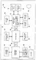
도 1 은 본 발명을 포함하는 기판 프로세싱 시스템의 평면도이다.1 is a plan view of a substrate processing system incorporating the present invention.
도 2 는 본 발명의 일 실시형태에 따른 예시적 기판 세정 시스템의 간략화된 측면도이다.2 is a simplified side view of an exemplary substrate cleaning system in accordance with an embodiment of the present invention.
도 3 은 선 3-3 을 따라 자른, 도 2 에 도시된 담금 탱크 및 기판 이송 시스 템의 측면도이다.3 is a side view of the immersion tank and substrate transfer system shown in FIG. 2, taken along line 3-3.
도 4 는 본 실시형태의 일 실시형태에 따라 기판 표면으로부터 미립자 오염물을 제거하도록 이용된 액체를 나타내는 평면도이다.4 is a plan view showing a liquid used to remove particulate contaminants from a substrate surface in accordance with one embodiment of the present embodiment.
도 5 는 본 발명에 따라 도 4 의 오염물과 관련된 현탁액 (suspension) 내의 연성 (malleable) 영역의 상대적 단면적을 나타낸다.5 shows the relative cross-sectional area of a malleable region in the suspension associated with the contaminant of FIG. 4 in accordance with the present invention.
도 6 은 본 발명에 따라 웨이퍼 표면으로부터 미립자 오염물을 제거하는 것을 촉진하는 미립자 상에 가해진 힘을 나타내는, 도 4 에 도시된 이용된 액체의 평면도이다.FIG. 6 is a top view of the used liquid shown in FIG. 4 showing the force applied on the particulates to facilitate removal of particulate contaminants from the wafer surface in accordance with the present invention.
도 7 은 도 2 및 도 3 에 도시된 기판을 세정하는 프로세스를 나타내는 흐름도이다.7 is a flowchart illustrating a process for cleaning the substrate shown in FIGS. 2 and 3.
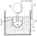
도 8 은 대안의 실시형태에 따른 도 4 에 도시된 담금 탱크의 단면도이다.8 is a cross-sectional view of the immersion tank shown in FIG. 4 according to an alternative embodiment.
도 9 는 본 발명의 다른 실시형태에 따라 기판 표면으로부터 미립자 오염물을 제거하도록 이용된 액체를 나타내는 평면도이다.9 is a plan view showing a liquid used to remove particulate contaminants from a substrate surface in accordance with another embodiment of the present invention.
도 10 은 대안의 실시형태에 따라 기판을 세정하도록 이용된 시스템의 사시도이다.10 is a perspective view of a system used to clean a substrate in accordance with an alternative embodiment.
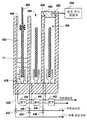
도 11 은 도 10 에 도시된 담금 탱크의 단면도이다.FIG. 11 is a cross-sectional view of the immersion tank shown in FIG. 10.
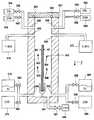
도 12 는 도 10 및 도 11 에 도시된 담금 탱크들 중 하나의 대안의 실시형태이다.12 is an alternative embodiment of one of the immersion tanks shown in FIGS. 10 and 11.
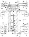
도 13 은 도 11 에 도시된 담금 탱크 중 하나의 대안의 실시형태이다.FIG. 13 is an alternative embodiment of one of the dip tanks shown in FIG. 11.
도 14 는 리드가 제거된 상태의 도 13 에 도시된 담금 탱크의 단면이다.FIG. 14 is a cross section of the immersion tank shown in FIG. 13 with the lid removed. FIG.
발명의 상세한 설명Detailed description of the invention
다음 설명에서, 본 발명의 전체 이해를 제공하기 위해 다수의 특정 상세들이 설명된다. 그러나, 본 발명이 이들 특정 상세들의 일부 또는 모두 없이 실시될 수도 있다는 것이 당업자에게 명백할 것이다. 다른 경우에서, 본 발명을 불필요하게 모호하지 않게 하기 위해 공지된 프로세스 동작들을 상세히 설명하지 않았다.In the following description, numerous specific details are set forth in order to provide a thorough understanding of the present invention. However, it will be apparent to those skilled in the art that the present invention may be practiced without some or all of these specific details. In other instances, well known process operations have not been described in detail in order not to unnecessarily obscure the present invention.
도 1 을 참조하면, 본 발명의 실시형태는 통상적으로 클러스터 툴 (10) 로서 지칭되는, 배열된 복수의 프로세싱 모듈을 포함하는 기판 프로세싱 시스템 내에 포함된다. 통상적으로, 클러스터 툴 (10) 은 둘러싸는 벽들 (14) 에 의해 부분적으로 정의되는 클린룸 (12) 내에 위치한다. 통상적으로, 클러스터 툴 (10) 의 모듈은 하나 이상의 로드/언로드 스테이션을 포함하고, 이 중 2 개의 스테이션이 16 및 18 로 도시된다. 클러스터 툴 (10) 의 내부 환경은, 방지되지 않는 경우, 프로세싱 동안 클린룸 (12) 의 환경에 기판의 노출을 최소화하도록 제어된다. 스테이션들 (16 및 18) 은 클린룸 (12) 과 클러스터 툴 (10) 의 모듈 사이에서 기판 (20) 의 이송을 용이하게 한다. 스테이션들 (16 및 18) 중 하나로부터, 기판 (20) 은 랩-환경 제어된 이송 모듈 (22) 안으로 도입되어 습식 프로세싱이 수행되는 것을 용이하게 할 수도 있다.Referring to FIG. 1, an embodiment of the present invention is included in a substrate processing system that includes a plurality of arranged processing modules, commonly referred to as
랩-환경 제어된 이송 모듈 (22) 을 통해 기판 (20) 에 의한 습식 프로세싱 모듈들 (24, 26 및 28) 에 대한 액세스가 획득된다. 랩-환경 제어된 이송 모듈 (22) 은, 그 기판 (20) 이 습식 프로세싱 모듈들 (24, 26 및 28) 의 각 모듈 안으 로 진입하기 전에 건조 상태로 남는 것을 보장하도록 기능한다. 이를 위해, 습식 프로세싱 모듈들 (24, 26 및 28) 각각은 프로세싱의 완료시 기판 (20) 의 표면을 건조시키는 기능을 한다. 기판 (20) 의 세정 후에, 플라즈마 프로세싱 모듈들 (30 및 32) 로의 액세스는 로드 록 (34) 및 진공 이송 모듈 (36) 을 통해 달성된다.Access to the
진공 이송 모듈 (36) 은 반도체 기판 위에 필름을 증착하기에 적절한 공지된 임의의 플라즈마 기상 증착 프로세싱 시스템일 수도 있는 플라즈마 프로세싱 모듈들 (30 및 32) (예를 들어, 하나 이상의 플라즈마 프로세싱 모듈이 PECVD (plasma enhanced chemical vapor deposition) 시스템일 수도 있음) 과 인터페이싱한다. 플라즈마 프로세싱을 하기 전/후 또는 하지 않고 에치 시스템 모듈 (40) 에서의 에치 프로세싱 또는 도금/증착 모듈 (38) 에서의 프로세싱을 하기 위해, 기판 (20) 은 로드 록 (42) 을 통해 횡단된다. 로드 록 (42) 을 횡단한 후에, 기판은 클린룸 (12) 의 공기에 기판을 노출하지 않고 모듈들 (38 및 40) 로의 액세스를 용이하게 하는 제어된 대기 이송 모듈 (44) 로 들어간다.
환경 제어 시스템 (150) 은 모듈들 (16, 18, 20, 22, 24, 26, 28, 30, 32, 34, 36, 38, 40, 42 및 44) 과 유체 소통 및 전기적 소통하여, 그 모듈들 내에 존재하는 환경이 원하는 프로세싱에 적합하도록 모듈들 (16, 18, 20, 22, 24, 26, 28, 30, 32, 34, 36, 38, 40, 42 및 44) 각각의 동작을 조정한다. 클러스터 툴의 예는 본 명세서에 참조로서 통합되는 미국 특허출원번호 제 11/639,752 호에서 논의된다.The environmental control system 150 is in fluid and electrical communication with the
도 1 및 도 2 양자 모두를 참조하면, 도면의 하나 이상의 습식 프로세싱 모듈들 (24, 26 및 28) 의 실시형태는 알루미늄, 플라스틱 등과 같은 임의의 적절한 재료로 형성된 바디 (51) 를 포함한다. 바디 (51) 는 담금 탱그 (52) 를 정의하고, 이 담금 탱크 (52) 는 단부 (53) 로부터 이격되어 보이드 (54) 를 정의하며, 이 보이드 (54) 사이에 도관 (55) 이 통과하여 담금 탱그 (52) 가 추가적인 시스템 (미도시) 과 유체 소통하도록 한다. 탱크 개구 (57) 는 담금 탱크 (52) 의 폐단부 (58) 에 대향되어 배치된다. 쉘빙 (shelving) 시스템 (60) 이 개구 (57) 에 대향되어 위치한다. 하나 이상의 베이스들 (61) 이 쉘빙 시스템 (60) 위에 배치될 수도 있다. 쉘빙 시스템 (60) 은 개구 (57) 에 근접한 제 1 위치 (미도시) 와 개구 (57) 에 대하여 멀리 위치한 제 2 위치 사이에서 왕복운동 하도록 동작한다. 이를 위해, 쉘빙 시스템 (60) 이 이동하는 것을 따라 트랙 (62) 이 제공된다. 제 2 위치에서, 개구 (57) 는 가로막히지 않고, 담금 탱크 (52) 로의 액세스를 허용한다.Referring to both FIGS. 1 and 2, an embodiment of one or more
베이스 (61) 위에는 반도체 기판 (64) 과 같은 기판을 유지하도록 동작하는 기판 카세트 (63) 가 배치된다. 카세트 (63) 와 탱크 (52) 사이에서 기판 (64) 을 이동시키기 위해, 기판 이송 시스템 (STS; 65) 이 담금 탱크 (52) 가까이에 위치한다. STS (65) 는 픽커 암 (picker arm; 67) 이 커플링된 로봇 (66) 을 포함한다. 픽커 암 (67) 은 거기에 커플링된 픽커 (68) 를 갖고, 이 픽커 (68) 는 엔드 이펙터 (end effector; 69) 를 갖는다. 픽커 암 (67) 은 로봇 (66) 에 의해 제어되어 이동하고, 담금 탱크 (52) 에 대하여 픽커 (68) 를 인덱싱하여 담금 탱크 (52) 내의 엔드 이펙터 (69) 의 위치를 정할 수 있다. 이를 위해, 로봇 (66) 은 스텝퍼 모터, 서보 모터, 또는 다른 유형의 모터를 포함하여 픽커 암 (67) 의 정확한 제어를 제공할 수도 있다. 픽커 암 (67) 은, 카세트 (63) 에서 탱크 (52) 내에 배치된 카세트 (70) 으로의 기판 (64) 이동을 용이하게 하기 위해, 2 개의 가로지른 방향으로 배향된 면들을 따라 확장하도록 엔드 이펙터 (69) 를 피봇하도록 구성된다. 이를 위해, 엔드 이펙터 (69) 에는 기판 (64) 을 조정하기 위한 적절한 크기 및 기능이 제공된다.Above the
본 실시예에서, STS (65) 는 픽커 암 (67) 이 담금 탱크 (52) 의 외부에 위치한 상태로 도시된다. STS (65) 는 카세트 (70) 내에 배치된 기판 (64) 보다 낮은 레벨까지 담금 탱크 (52) 안으로 픽커 (68) 의 삽입을 용이하게 한다. 그 결과, 기판 (64) 은 담금 탱크 (52) 내에서 처리되어 기판 (64) 의 표면 상에 존재하는 미립자 물질을 제거할 수도 있다. 이를 위해, 담금 탱크 (52) 는, 기판 (64) 의 모든 면들의, 전체 면적이 아니라면, 대부분이 세정 용액에 의해 커버되는 것을 허용하기에 충분한 양의 세정 용액 (71) 을 포함한다.In this embodiment, the
도 2, 도 3 및 도 4 를 참조하면, 쉘빙 시스템 (60) 이 제 2 위치에 있을 때 개구 (57) 가 노출되어, 행거 암 (73) 에 부착된 행거 (72) 와 마주 향하고 있는 탱크 (52) 내에 카세트 (70) 를 도입하고 유지하기 위한 액세스가 방해받지 않도록 허용한다. 행거 암 (73) 은 모터 (미도시) 에 커플링되어 담금 탱크 (52) 내에서의 카세트 (70) 의 위치를 변화시킨다. 본 발명의 일 실시형태에서, STS (65) 는, 다수의 기판들 (64) 을 갖고 로딩될 때 카세트 (70) 를 담금 탱크 (52) 안으로 이동시키는데 이용된다. 이 방식으로, 기판 (64) 의 배치 (batch) 프로세싱이 세정 프로세스 동안 착수될 수도 있다. 예를 들어, 기판 (64) 은 그 위에 오염물 (75) 을 가질 수도 있다. 담금 탱크는 용액으로 채워질 수도 있다. 픽커 암 (67) 은 카세트 (70) 상의 멈춤쇠 (detent; 77) 를 커플링하여 이를 담금 탱크 (52) 안팎으로 이동한다. 용액 내에서 카세트 (70) 의 운동은 기판 (64) 의 표면으로부터 오염물 (75) 로서 지칭되는 잔류물, 화학물 및 미립자를 느슨하게 하고, 부드럽게 하고, 몰아내고, 또는 그 외에 제거를 강화시킨다. 카세트 (70) 가 담금 탱크 (52) 안으로 도입되는 속도는 기판 (64) 으로부터 오염물 (75) 의 제거를 용이하게 하도록 확립된다. 구체적으로, 용액은 오염물 (75) 과 상호작용하고 기판 (64) 의 표면으로부터 오염물을 제거하기에 적절한 특성을 갖도록 제조된다. 유사하게, 카세트 (70) 가 용액 (71) 으로부터 제거되는 속도 또한 기판 (64) 으로부터 오염물의 제거를 용이하게 한다. 그 결과, 용액 (71) 이 존재하기 전에 카세트 (70) 및 기판을 담금 탱크 (52) 안으로 도입시키는 것이 가능하다. 카세트 (70) 및 기판 (64) 이 담금 탱크 (52) 내에 존재한 후에, 용액 (71) 이 도입되고, 기판들 (64) 각각에 대한 용액 (71) 의 운동은 기판으로부터 오염물 (75) 의 제거를 용이하게 한다. 담금 탱크 (52) 로부터 기판 (64) 의 제거 후에, 기판은 린스 프로세스에 노출되어 용액 (71) 을 제거하고/하거나 남아있는 오염물을 느슨하게 할 수도 있다. 이는, 예를 들어, 나머지 습식 프로세싱 모듈들 (24, 26 및 28) 중 하나에서, 배치 린스를 용이하게 하는 IPA 의 용액 또는 DIW (de-ionized water) 의 용액을 갖는 린스 상태의 탱크 (미도시) 안 으로 기판 (64) 으로 가득찬 카세트 (70) 를 삽입함으로써 발생할 수도 있다. 종래 기술에서 잘 알려진 린스 스테이션으로의 이동을 위한 로봇 (66) 에 의해 기판 (64) 이 회수되는 공간 (76) 안으로 기판을 들어올리는 픽커 암 (67) 에 의해 카세트 (70) 로부터 개별적으로 각 기판 (64) 을 제거하도록 STS (65) 가 채용될 수도 있다는 것을 이해하여야 한다.2, 3 and 4, when the
도 3 및 도 4 를 참조하면, 용액 (71) 을 형성할 수도 있는 예시의 재료는, 영역들 중 하나와 연관된 흐름 특성이 나머지 영역과 연관된 흐름 특성들과 상이하도록 흐름 특성들을 상이하게 한 다수의 영역들을 갖는 현탁액 (90) 을 포함한다. 본 실시예에서, 현탁액 (90) 은 액체 영역 (92) 및 커플링 엘리먼트 (94) 를 포함한다. 액체 영역 (92) 은 이와 함께 연관된 제 1 점성을 갖는다. 커플링 엘리먼트 (94) 는 강성 고체 바디, 연성 고체 바디 또는 유동성 특성을 갖는 고체 바디, 즉 액체 영역 (92) 과 연관된 점성보다 훨씬 더 큰 점성을 갖는 고체 바디를 포함할 수도 있다. 커플링 엘리먼트 (94) 는, 기판 (64) 의 표면 (98) 상에 존재하는 미립자 오염물 (75) 가까이에 커플링 엘리먼트 (94) 를 배치하는 것을 촉진하는데 있어서 액체 영역 (92) 이 커플링 엘리먼트 (94) 에 대한 이송체로서 기능하도록, 액체 영역 (92) 전체에 걸쳐 혼입된다.With reference to FIGS. 3 and 4, an example material that may form the
커플링 엘리먼트 (94) 는 현탁액 (90) 으로부터 커플링 엘리먼트 (94) 와 맞대고 있는 오염물 (75) 로의 힘의 이송, 즉 액체 영역 (92) 의 운동을 통해 표면 (98) 으로부터 오염물 (75) 을 제거할 수 있는 재료로 이루어진다. 따라서, 표면 (98) 으로부터 오염물 (75) 을 제거하기 위해 충분한 단면적을 갖는 커플링 엘 리먼트 (94) 를 제공하는 것이 바람직하다. 통상적으로, 커플링 엘리먼트 (94) 의 단면적은 오염물 (75) 의 단면적보다 더 크다. 이 방식에서, 드래그 힘


오염물 (75) 의 표면 상의 드래그 힘


도 6 을 참조하면, 커플링 엘리먼트 (94) 에 맞대고 있는 오염물 (75) 로 전달되는 힘은 하나 이상의 각종 메커니즘을 통해 커플링 엘리먼트 (94) 의 커플링을 통해 오염물로 발생한다. 이를 위해, 커플링 엘리먼트 (94) 가 표면 (98) 상의 오염물 (75) 과 접촉하거나 매우 근접하도록, 액체 영역 (92) 은 액체 영역 (92) 내의 커플링 엘리먼트 (94) 상에 하향의 힘

하나의 이러한 커플링 메커니즘은 커플링 엘리먼트 (94) 와 오염물 (75) 사이의 기계적 접촉이다. 이를 위해, 커플링 엘리먼트 (94) 는 오염물 (75) 에 비해 다소 연성일 수도 있다. 커플링 엘리먼트 (94) 가 오염물 (75) 보다 더 연성인 실시형태에서, 오염물 (75) 에 대해 가해지는 힘은 오염물 (75) 과의 충격으로부터 발생하는 커플링 엘리먼트 (94) 의 변형으로 인해 감소된다. 그 결과, 오염물 (75) 은 커플링 엘리먼트 (94) 내에 찍힐 수도 있고/있거나 커플링 엘리먼트 (94) 의 네트워크 내에 걸릴 수도 있다. 이는, 커플링 엘리먼트 (94) 와 오염물 (75) 간의 기계적 연계를 생성하여 그들 사이의 상대적인 위치를 고정할 수도 있다. 기계적 응력은 커플링 엘리먼트 (94) 에서 오염물 (75) 로 전달될 수도 있고, 이에 의해 오염물 (75) 이 표면 (98) 으로부터 떨어져 나올 가능성이 증가한다. 또한, 오염물 (75) 과 커플링 엘리먼트 (94) 간의 접착과 같은 화학적 커플링 메커니즘이 발생할 수도 있다.One such coupling mechanism is the mechanical contact between the
커플링 엘리먼트 (94) 및 오염물 (75) 이 충분히 단단한 경우, 실질적으로 탄성 충돌이 발생하여 커플링 엘리먼트 (94) 로부터 오염물 (75) 로 상당한 에너지의 전달을 초래하고, 이에 의해 오염물 (75) 이 표면 (98) 으로부터 떨어져 나올 가능성이 증가한다. 그러나, 커플링 엘리먼트 (94) 와 오염물 (75) 간 접착의 화학적 커플링 메커니즘이 약화될 수도 있고, 이는 충돌에 의해 얻어지는 가능성을 감소시킬 수도 있다.When the
또한, 전술된 기계적 및 화학적 커플링 메커니즘에 대해 정전 커플링이 발생할 수도 있다. 예를 들어, 커플링 엘리먼트 (94) 및 오염물 (75) 은 반대의 표면 전하를 갖고, 이들은 전기적으로 끌어당긴다. 커플링 엘리먼트 (94) 와 오염물 (75) 간의 정전 인력은 표면 (98) 에 오염물 (75) 을 연결시키는 힘을 극복하기에 충분할 수 있다. 하나 이상의 전술된 커플링 메커니즘은 표면 상의 하나 이상의 오염물 (75) 에 대하여 소정 시간에서 발생될 수도 있다. 또한, 이는 랜덤하게 발생할 수도 있고, 또는 상이한 재료로 형성된, 그리고 상이한 형상 및 강도를 갖는 커플링 엘리먼트 (94) 를 가짐으로써 유도될 수도 있다. 대안으로, 접근하는 커플링 엘리먼트 (94) 와 오염물 (75) 간의 정전 반발 상호 작용이 표면 (98) 으로부터 오염물 (75) 을 제거하기에 충분히 강할 수도 있다.In addition, electrostatic coupling may occur for the mechanical and chemical coupling mechanisms described above. For example,
도 2, 도 4 및 도 7 을 참조하면, 커플링 엘리먼트 (94) 의 오염물 (75) 과의 상호작용은 기판 (64) 과 용액 (71) 사이에 상대적 운동을 생성함으로써 부분적으로 달성된다. 전술한 바와 같이, 현탁액 (90) 과 기판 (64) 사이의 상대적 운동은, 커플링 엘리먼트 (94) 가 오염물 (75) 에 충격을 주는 것을 허용하기에 충분한 운동량을 가하고, 기판 (64) 의 표면 (98) 으로부터 오염물을 운동시키기에 충분한 드래그 힘
도 4 및 도 8 양자 모두를 참조하면, 다른 실시형태에서 카세트 (70) 는 용 액 (71) 이 없는 담금 탱크 (52) 안으로 내려진다. 구체적으로, 카세트 (70) 는 지지체 (95) 에 의해 폐단부 (58) 위에 지지되는 선반 (93) 위에 놓여진다. 그 후, 용액 (71) 이 샤워헤드 (101) 에 의해 담금 탱크 (52) 안으로 도입된다. 이를 위해, 용액 (71) 의 공급기 (103) 와 유체 소통하는 샤워헤드 (101) 는 그 안에 혼입된 커플링 엘리먼트 (94) 를 갖는 용액 (71) 의 복수의 흐름을 생성하도록 설계된다. 담금 탱크 (52) 안으로의 용액 (71) 의 진입과 함께 도관 (55) 이 탱크로부터 용액을 제거하도록 드레인으로서 기능할 수도 있다. 샤워헤드 (101) 는, 기판 표면으로부터 오염물 (75) 을 제거하도록 충분한 양의 시간 동안 각각의 기판 (64) 의 대향면 위에서 흐르는 용액 (71) 의 커튼을 생성하도록 구성된다. 본 발명의 다른 실시형태에서, 도관 (55) 이 닫혀져, 용액 (71) 이 샤워헤드 (101) 에서 빠져나와 담금 탱크 (52) 내에 축적되는 것을 허용하고, 기판 (64) 이 용액 (71) 내에 잠기게 되는 것을 허용할 수도 있다. 이는 각각의 도관 (55) 에 펌프 시스템 (106) 을 커플링함으로써 착수되어, 도관을 통한 유량을 제어할 수도 있다. 포스트 (95) 는 선반이 위치 (105) 와 위치 (107) 사이에서 왕복운동 하는 것을 허용하도록 구성될 수도 있다. 이 방식으로, 용액 (71) 과 각 기판 (64) 의 대향면 사이의 상대적 운동은 화살표 109 로 도시된 바와 같이 대향 방향을 따라 발생할 수도 있다.4 and 8, in another embodiment the
현탁액 (90) 의 예시적인 실시형태는 약 1 센티푸아즈 (Centipoises; cP) 내지 약 10,000 cP 사이의 점도를 갖는 액체 영역 (92) 을 포함한다. 또한, 액체 영역 (69) 은 뉴턴 유체 또는 비-뉴턴 유체일 수도 있다. 액체 영역 (92) 으로 서 이용될 수도 있는 예시적인 재료들로는 DIW (de-ionized water), 탄화수소, 불화탄소, 광유 (mineral oil) 또는 알콜 등이 있다. 또한, 현탁액 (90) 은 이온 또는 넌-이온 용매 및 다른 화학 첨가제를 포함할 수도 있다. 예를 들어, 현탁액 (90) 에 대한 화학 첨가제는 공용매 (co-solvent), pH 개질제, 킬레이트 시약, 극성 용매, 계면 활성제, 암모니아 수산화물, 과산화수소, 플루오르화 수소산, 테트라메틸 암모늄 수산화물, 및 폴리머, 미립자, 및 폴리펩티드와 같은 유동성 개질제의 임의의 조합을 포함할 수 있다.Exemplary embodiments of the
커플링 엘리먼트 (94) 는, 전술된 특성들에 추가하여 표면 (98) 과 접촉하거나 매우 근접하게 위치한 경우 표면 (98) 에 부착되지 않도록 본질적으로 임의의 서브-상태를 나타내는 물리적 특성을 소유한다. 또한, 커플링 엘리먼트 (94) 와 표면 (98) 사이의 접착력 뿐만 아니라, 커플링 엘리먼트 (94) 에 의해 표면 (98) 에 야기된 손상이 차감되어야 한다. 일 실시형태에서, 커플링 엘리먼트 (94) 의 경도는 표면 (98) 의 경도보다 작다. 또한, 표면 (98) 과 접촉하거나 매우 근접하게 위치할 때 커플링 엘리먼트 (94) 가 표면 (98) 에 부착하는 것을 방지하는 것이 바람직하다. 각종 실시형태에서 커플링 엘리먼트 (94) 는 다결정성 고체 또는 비-결정 고체로서 정의될 수도 있다. 비-결정 고체의 예로는 지방족산, 카르복시산, 파라핀, 왁스, 폴리머, 폴리스티렌, 폴리텝티드, 및 다른 점탄성 (visco-elastic) 재료를 포함한다. 이를 위해, 현탁액 (90) 내의 커플링 엘리먼트 (94) 의 양은 액체 영역 (92) 내에서 그 용해도 한계를 초과하는 농도로 존재해야 한다.The
지방족 산은, 카본 원자가 개방 체인을 형성하는 유기 화합물에 의해 정의되는 임의의 산을 본질적으로 나타내는 것으로 이해되어야 한다. 지방산은 현탁액 (90) 내의 커플링 엘리먼트 (94) 로서 이용될 수 있는 지방족 산의 일 예이다. 이용될 수도 있는 지방산의 예들로는, 라우르산, 팔미트산, 스테아르산, 올레산, 리놀레산, 리놀렌산, 아라키돈산, 가돌레산, 에루신산, 부티르산, 카프로산, 카프릴산, 미리스트산, 마르가르산, 베헤닉산, 리그노세린산, 미리스톨레인산, 팔미톨레산, 네르본산 (nervanic acid), 파리나린산, 팀노돈산, 브라신산, 클루파노돈산, 리그노세린산, 세로틴산, 및 그 혼합물 등이 있다.Aliphatic acids are to be understood as representing essentially any acid defined by an organic compound in which carbon atoms form an open chain. Fatty acids are an example of aliphatic acids that can be used as
일 실시형태에서, 커플링 엘리먼트 (94) 는 C-1 에서 약 C-26 까지 연장되는 각종 탄소 체인 길이로 형성된 지방산의 혼합물을 나타낼 수도 있다. 카르복실산은 하나 이상의 카르복실기 (COOH) 를 포함하는 임의의 유기 산에 의해 본질적으로 정의된다. 커플링 엘리먼트 (94) 로서 이용되는 경우, 카르복실산은 C-1 내지 약 C-100 까지 연장된 각종 탄소 체인 길이의 혼합물을 포함할 수 있다. 또한, 카르복실산은 비제한적으로 메틸, 비닐, 알킨, 아미드, 1 차 아민, 2 차 아민, 3 차 아민, 아조, 니트릴, 니트로, 니트로조, 피리딜, 카르복실, 페록시, 알데히드, 케톤, 1 차 이민, 2 차 이민, 에테르, 에스테르, 할로겐, 이소시아네이트, 이소티오시아네이트, 페닐, 벤질, 포스포디에스테르, 설프하이드릴과 같은 다른 관능기를 포함할 수 있으나, 현탁액 (90) 에서 불용해성을 여전히 유지한다.In one embodiment, the
카르복실산 성분으로부터 형성된 영역을 갖는 현탁액 (90) 을 형성하기 위한 일 방식은, DIW (de-ionized water) 를 갖고 약 3 % 내지 약 50 wt% 사이, 바람직 하게는 약 4% 내지 약 20 wt% 사이 등의 카르복실산 고체의 농도로 형성되는 겔 (gel) 로서 액체 영역 (69) 을 나타내는 것을 포함한다. 고체가 용액으로 되는 것, 즉 용해되는 것을 용이하게 하는 것을 포함하여, 55 ℃ 내지 약 85 ℃ 로 가열된 용액 및 혼합물에 수산화암모늄이 추가될 수도 있다. 일단, 고체가 용해되면 세정 용액이 냉각될 수 있다. 냉각 프로세스 동안, 바늘 또는 판 형태의 고체 화합물이 침전된다. 이 방식으로 형성된 예시의 현탁액 (90) 은 초당 0.1 전단 레이트에서 약 1000 cP 의 점도를 갖고, 이 점도는 전단 레이트가 초당 1000 까지 증가하는 경우 (즉, 비-뉴턴 유체인 경우) 약 10 cP 로 떨어진다. 현탁액은, 이용될 수도 있는 물, 알콜과 같은 극성 또는 비-극성 용매 이외의 용매에서 카르복실산(들) (또는 염) 에 의해 형성될 수도 있는 것으로 이해되어야 한다.One way to form a
커플링 엘리먼트 (94) 를 갖는 현탁액 (90) 의 다른 실시형태는 가수분해된 화학제로부터, 또는 계면활성제를 포함함으로써 형성된다. 예를 들어, 분산제가 액체 영역 (92) 내에 포함되어, 현탁액 (90) 전체에 걸쳐 커플링 엘리먼트 (94) 의 분산을 용이하게 할 수도 있다. 이를 위해, 현탁액 (90) 에는 염기 (base) 가 추가되어, 화학적량보다 적게 존재하는 카르복실산 또는 스테아르산과 같은 재료로부터 커플링 엘리먼트 (94) 의 혼입을 가능하게 할 수 있다. 예시의 염기로는 수산화암모늄이 있으나, 임의의 상용 가능한 염기가 본 명세서에 설명된 실시형태에 이용될 수도 있다. 또한, 커플링 엘리먼트 (94) 가 형성되는 재료의 표면 기능성은 카르복실산염, 인산염, 황산염기, 폴리올기, 에틸렌 산화물 등과 같은 현탁액 (90) 내에 혼합 가능한 일부를 포함하는 것에 의해 영향 받을 수도 있다. 이 방식으로, 원하지 않는 현탁액의 응집을 피하면서 커플링 엘리먼트 (94) 를 현탁액 (90) 전체에 걸쳐 분산시키는 것, 즉 실질적으로 균질의 현탁액 (90) 을 형성하는 것이 가능할 수도 있다. 이 방식으로, 커플링 엘리먼트 (94) 의 응집이 표면 (98) 으로부터 오염물 (96) 을 커플링 및/또는 제거하기에 불충분해지는 상황을 방지할 수도 있다.Another embodiment of the
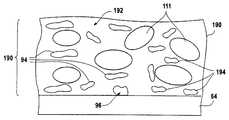
도 9 를 참조하면, 다른 대안의 실시형태에서, 현탁액 (190) 은 액체 영역 (192) 내에 혼입되는 비혼합성 성분 (111) 으로서 지칭된 추가의 성분을 포함할 수도 있다. 비혼합성 성분들은 재료의 기체상, 액상, 고체상, 또는 이들의 조합을 포함할 수도 있다. 본 실시예에서, 비혼합성 성분 (111) 은 현탁액 (190) 의 액체 영역 (192) 전체에 걸쳐 분산된 복수의 이격된 기체 포켓들 전체를 포함하는 영역이다. 비혼합성 성분은 현탁액 (190) 에 대해 2 볼륨% 내지 99 볼륨% 포함될 수 있다. 예시의 기체상 비혼합성 성분 (111) 은 다음의 기체들로부터 형성될 수도 있다: 질소 (N2), 아르곤 (Ar), 산소 (O2), 오존 (O3), 과산화수소 (H2O2), 공기, 수소 (H2), 암모늄 (NH3), 플루오르화수소산 (HF).Referring to FIG. 9, in another alternative embodiment, the
액상의 비혼합성 성분 (111) 은 펜탄, 헥산, 헵탄, 옥탄, 노난, 데칸과 같은 저-분자량 알칸, 또는 미네랄 오일을 포함할 수도 있다. 대안으로, 액상의 비혼합성 성분 (111) 은 오일 가용성 표면 개질제를 포함할 수도 있다. 도 4 및 도 9 양자 모두를 참조하면, 커플링 엘리먼트 (94) 가 커플링 엘리먼트 (94) 와 실질적으로 유사하고 액체 영역 (192) 이 액체 영역 (92) 과 실질적으로 유사한 상태 에서, 현탁액 (190) 은 오염물 (75) 을 제거하는 것에 대하여 현탁액 (90) 과 실질적으로 유사한 기능을 한다. 그러나, 현탁액 (190) 에서, 비혼합성 성분 (111) 은 오염물 (75) 과 접촉하거나 근접하여 커플링 엘리먼트 (194) 를 배치하는 것을 용이하게 한다. 이를 위해, 오염물 (75) 에 근접한, 또는 이와 접촉하는 하나 이상의 영역은 오염물 (75) 과 하나 이상의 비혼합성 성분 (111) 사이에 배치된다. 그것과 함께 연관된 표면 장력을 가지면, 비혼합성 성분 (111) 은 액체 영역 (192) 내의 힘에 응답하여 커플링 엘리먼트 (194) 상의 힘 (F) 을 커플링 엘리먼트 (194) 에 제시한다. 힘 (F) 은 표면 (98) 및 그에 따른 오염물 (75) 을 향해 커플링 엘리먼트 (194) 를 운동시킨다. 커플링 엘리먼트 (194) 및 오염물 (75) 에 대하여 전술된 임의의 방식으로 커플링 엘리먼트 (194) 와 오염물 (75) 간에 커플링이 발생할 수도 있다.The liquid
비혼합성 성분 (111) 은 기판 (64) 상에 배치되기 전에 현탁액 (190) 내에 혼입될 수도 있다. 대안으로, 비혼합성 성분 (111) 은, 현탁액이 표면 (98) 상에 퇴적될 때 인시추로 현탁액 (190) 내에 혼입될 수도 있고/있거나 현탁액 (190) 과 표면 (98) 의 충격에 의해 생성되어 이에 의해 주변 대기 내에 존재하는 공기와 같은 기체를 동반, 예를 들어 폼 (foam) 을 생성할 수도 있다. 일 예로, 현탁액 (190) 이 현탁액 (190) 의 압력에 비해 대기압에서 감소되는 동안, 비혼합성 성분 (111) 이 용액 밖으로 나오는 액체 영역 (192) 내에 용해된 기체로부터 생성될 수도 있다. 이 프로세스의 이점은, 커플링 엘리먼트 (194) 가 중력 하에 놓여 표면 (98) 을 향해 이동되기 때문에 대다수의 비혼합성 성분 (111) 이 커플링 엘리 먼트 (194) 가까이에 형성된다. 이는, 커플링 엘리먼트 (194) 가 오염물 (75) 과 커플링되는 가능성을 증가시킨다.The
이중 상태 (bi-state) 현탁액 (90) 과 비교하여, 삼중 상태 (tri-state) 현탁액 (190) 은 추가의 성분들을 포함하여, 커플링 엘리먼트 (194) 와 오염물 간의 커플링 메커니즘을 변형 및 개선할 수도 있다. 예를 들어, 액체 매질의 pH 는 정전 척력이 감소되거나 증폭되도록 고체 성분 및 오염물 중 일방 또는 양자 모두 상의 표면 전하를 취소하도록 변형될 수 있다. 또한, 현탁액 (190) 의 온도 사이클링은 그 특성을 제어 또는 변경하도록 이용될 수도 있다. 예를 들어, 커플링 엘리먼트 (94) 는 유연성이 온도에 비례 또는 반비례하여 변할 수도 있는 재료로 형성될 수도 있다. 이 방식으로, 일단 커플링 엘리먼트 (94) 가 오염물의 형상을 따르면, 현탁액의 온도가 변하여 그 유연성 (malleability) 을 감소시킨다. 또한, 현탁액 (190) 의 용해성 및, 그에 따른 커플링 엘리먼트 (94) 의 농도는 온도에 비례 또는 반비례하여 변할 수도 있다.Compared to the
예시의 현탁액 (190) 은 70 ℃ 이상으로 가열된 스테아르산 고체를 70 ℃ 이상으로 가열된 DIW 에 혼합시킴으로써 제조된다. DIW 와 혼합된 스테아르산 고체의 양은 대략 0.1 중량% 내지 10 중량% 이다. 이 화합물은 DIW 내에 스테아르산 성분을 분산시키고/유화시키기에 충분하다. 화합물의 pH 레벨은 9 보다 높게 조정되어 스테아르산 성분을 중화한다. 이는, 0.25 중량% 내지 10 중량% 의 농도를 제공하기 위해 수산화 암모늄 (NH4OH) 과 같은 염기를 추가함으로써 달성 된다. 이 방식으로, 산-염기 혼합물이 형성되고, 이는 20 분 동안 휘저어져 혼합물의 균질성을 확보한다. 산-염기 혼합물은 지방산염이 커플링 엘리먼트 (194) 를 침전시키고 형성하는 것을 허용하는 대기 온도에 도달하도록 허용된다. 침전 동안 형성된 커플링 엘리먼트 (194) 는 0.5 내지 5000 마이크로미터 범위 내의 크기에 도달하는 것이 바람직하다. 원하는 경우, 혼합물이 휘저어지기 때문에 비혼합성 성분 (111) 이 산-염기 혼합물 내의 공기의 혼입으로부터 형성될 수도 있다.
다른 실시형태에서, 현탁액 (190) 은 0.5 내지 5000 마이크로미터 범위 내의 입자 크기로 가공된 과립형 스테아르산 고체로부터 형성된다. 과립형 형태로 가공된 스테아르산이 DIW 에 추가되는 동시에 이를 교반하여 산-DIW 혼합물을 형성한다. DIW 의 교반은 흔들기, 휘젓기, 회전 등과 같은 공지의 임의의 수단에 의해 발생할 수도 있다. 스테아르산은 대략 0.1 중량% 내지 10 중량% 의 산-DIW 혼합물을 형성한다. 스테아르산의 해리는 염기를 추가함으로써 산-DIW 혼합물의 pH 레벨을 대략 9 로 확립함으로써 달성된다. 예시의 염기는 0.5 중량% 내지 10 중량% 농도의 수산화 암모늄 (NH4OH) 을 포함한다. 염기는 암모늄 스테아르산염 입자를 형성하는 스테아르산 성분을 중화한다. 통상적으로, NH4OH 가 산-DIW 혼합물에 추가되는 동시에 이를 교반하여, 산-DIW 혼합물 전체에 걸쳐 응고된 스테아르산 입자를 분산시킨다. 이들 응고된 암모늄 스테아르산염 입자의 크기 분포는 0.5 내지 5,000 마이크로미터이다.In another embodiment, the
또다른 실시형태에서, 현탁액 (190) 은 전술된 바와 같이 이소프로필 알콜 (IPA) 이 교반되면서 IPA 내에 용해된 스테아르-팔미트산 (Stearic-palmitic acid) 혼합물로부터 형성된다. 이는 2 중량% 내지 20 중량% 범위의 농도 내에 존재하는 용해된 지방산의 농도를 제공한다. IPA 의 끓음을 방지하면서 IPA 를 가열하는 것 및/또는 아세톤, 벤젠 또는 이들의 조합과 같은 유기 용매를 추가하는 것은 지방산의 용해도를 향상시킬 수도 있다. 이하 용해의 농도에서 남아있는 임의의 고체는 고체가 없는 (solid-free) 용액을 생성하는 여과 또는 원심분리 기술에 의해 제거될 수도 있다. 고체가 없는 용액은 물과 같은 비-용매인 액체와 함께 지방산에 혼합되어 지방산 고체를 응결시킬 수도 있다. 응결된 지방산은 0.5 내지 5,000 미크론 범위 내의 크기 분포를 갖고 용액 내에 부유된다. 스테아르산 성분은 전술된 바와 같이 이온화될 수도 있다.In another embodiment, the
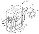
도 10 을 참조하여 본 발명의 다른 실시형태에 따르면, 기판 세정 시스템 (400; SCS) 은 402, 404 및 406 으로 도시된 복수의 담금 탱크를 포함한다. 담금 탱크들 (402, 404 및 406) 각각은 전술된 현탁액들 중 어느 하나, 예를 들어 현탁액 (90 또는 190) 을 포함할 수도 있다. 픽커 (picker) 시스템은 408, 410 및 412 로 도시된 다수의 픽커들을 포함한다. 픽커들 (408, 410 및 412) 각각은 트랙 (414) 을 따라 왕복운동하도록 커플링되므로, 픽커들 (408, 410 및 412) 중 어느 하나에 의해 고정된 기판 (64) 은 담금 탱크들 (402, 404 및 406) 중 어느 하나 내에 배치될 수도 있다. 시스템 (400) 은 컴퓨터 판독가능 메모리 (418) 와 데이터 통신하는 프로세서 (416) 의 제어 하에서 동작된다. 프로세서 (416) 는 기판 (64) 을 담금 탱크들 (402, 404 및 406) 안으로 잠기게 하도록 시스템 (400) 의 동작을 제어한다. 이를 위해, 프로세서는 트랙 (414) 을 따라 픽커들 (408, 410 및 412) 을 이동시키고, 뿐만 아니라 담금 탱크들 (408, 410 및 412) 의 안팎으로 기판 (64) 을 이동시키는 기능을 하는 모터 (420) 와 데이터 통신한다. 프로세서는 또한, 담금 탱크들 (408, 410 및 412) 안으로 유체의 도입을 조절하도록 유체 공급기들 (422, 424 및 426) 과 데이터 통신한다. 또한, 프로세서 (416) 는 그 동작을 제어하도록, 예를 들어 담금 탱크들 (408, 410 및 412) 로부터 유체의 배출을 허용하도록 담금 탱크들 (408, 410 및 412) 과 데이터 통신한다.According to another embodiment of the present invention with reference to FIG. 10, the substrate cleaning system 400 (SCS) includes a plurality of soaking tanks, shown as 402, 404, and 406. Each of the
도 10 및 도 11 양자 모두를 참조하면, 동작 시에, 피커 (408) 로서 도시된 피커들 (408, 410 및 412) 중 하나는 기판 (64) 을 담금 탱크 (402) 로서 도시된 담금 탱크들 (402, 404 및 406) 중 하나 안에 놓는다. 담금 탱크 (402) 내에 있는 동안 기판 (64) 은 지지체 (428) 위에 놓인다. 그 다음에, 담금 탱크 (402) 는 용액 (71) 으로 충전된다. 용액 (71) 은 프로세서 (416) 의 동작 하에서 담금 탱크 (402) 안으로 도입되고, 프로세서는 유체 공급기 (422) 의 펌프 (미도시) 가 용액 (71) 을 도관 (430) 을 따라 거기로부터 그리고 적절한 담금 탱크 (402, 404 및 406) 안으로 이동하게 한다. 담금 탱크 (402, 404 및 406) 내로의 흐름을 제어하기 위해, 담금 탱크들 각각은 프로세서 (416) 와 데이터 통신하여 프로세서의 제어 하에서 동작되는 밸브들 (432, 434 및 436) 을 포함한다. 밸브 (432) 는 유체 공급기들 (422, 424 및 426) 로부터 담금 탱크 (402) 안으로 유체가 흐르는 것을 선택적으로 허용 및 방지한다: 밸브 (434) 는 유체 공급기들 (422, 424 및 426) 로부터 담금 탱크 (404) 안으로 유체가 흐르는 것을 선택적으로 허용 및 방지한다: 그리고, 밸브 (436) 는 유체 공급기들 (422, 424 및 426) 로부터 담금 탱크 (406) 안으로 유체가 흐르는 것을 선택적으로 허용 및 방지한다. 담금 탱크 (402, 404 및 406) 로부터의 배출 (drainage) 은 거기와 데이터 통신하는 펌프들 (438, 440 및 442) 을 제어하는 프로세서 (416) 에 의해 조절된다. 구체적으로, 담금 탱크 (402) 의 배출은 펌프 (438) 에 의해 실시되거나 방지되고; 담금 탱크 (404) 의 배출은 펌프 (440) 에 의해 실시되거나 방지되며; 담금 탱크 (406) 의 배출은 펌프 (442) 에 의해 실시되거나 방지된다.With reference to both FIGS. 10 and 11, in operation, one of the
일 모드의 동작 동안, 용액 (71) 이 유출구 (446) 에서 담금 탱크 (402) 안으로 도입되어 담금 탱크 (402) 위를 채운다. 이는 기판 (62) 이 담금 탱크 (402) 안으로 도입되기 전 또는 후에 달성될 수도 있다. 그러나, 통상적으로 기판 (64) 은 용액 (71) 의 도입 전에 담금 탱크 (402) 내에 위치한다. 다시 지지체 (428) 를 놓은 후에, 프로세서 (416) 는 용액 (71) 을 담금 탱크 (402) 안으로 도입한다. 용액 (71) 이 유출구 (446) 를 통해 도입됨에 따라, 프로세서 (416) 는 펌프 (438) 를 작동시켜 담금 탱크 (402) 로부터 용액 (71) 을 배출시킨다. 이 방식으로, 기판 (64) 은 용액 (71) 의 연속 흐름에 노출된다. 담금 탱크들 (402, 404 및 406) 각각이 기판 (64) 을 용액 (71) 의 연속 흐름에 동시에 노출시키는데 이용될 수도 있다. 이를 위해, 밸브들 (432, 434 및 436) 은 공급기들 (422, 424 및 426) 중 하나로부터 담금 탱크들 (402, 404 및 406) 로 용액 (71) 의 진입을 허용하도록 동작된다. 대안으로, 담금 탱크들 (402, 404 및 406) 중 하나 이상이 공급기들 (422, 424 및 426) 중 하나로부터 공급된 DIW 를 포함할 수도 있다. 용액 (71) 에 노출된 후에, 기판 (564) 은 DIW 에 노출됨으로써 린스된다. 이는 담금 탱크들 (402, 404 및 406) 중 하나를 DIW 로 채우고 그 안에 기판 (64) 을 도입함으로써 달성될 수도 있다. 대안으로, 기판 (64) 은 담금 탱크들 (420, 404 및 406) 중 하나 내에 존재할 수도 있고, 이 시간 후에 DIW 가 그 담금 탱크 내로 도입된다. 또한, 담금 탱크들 (402, 404 및 406) 중 하나는 현탁액 (90) 을 포함하는 한편, 나머지 담금 탱크들 (402, 404 및 406) 중 하나는 현탁액 (90) 을 포함하고 나머지 담금 탱크들 (402, 404 및 406) 은 DIW 를 포함할 수도 있다. 이 구성에서, 기판 (64) 은 DIW 로 린스되기 전에 현탁액들 (90 및 190) 양자 모두에 노출된다. 기판 (64), 현탁액 (90 및 190) 및 DIW 를 공통의 담금 탱크 (402) 내에 순차적으로 노출시키는 것이 가능하다. 원한다면, 헬륨과 같은 퍼지 가스 공급기 (454) 에 접속될 수도 있는 통로 (52) 를 포함하는 담금 탱크 (406) 를 실링하는 커버 (450) 로 도시된 바와 같이, 담금 탱크들 (402, 404 및 406) 은 기판 (64) 이 그 안에 배치된 후에 실링 (sealing) 될 수도 있다. 이 방식으로, 담금 탱크 (406) 는, 회피되지 않는 경우, 기판 (84) 의 이른 건조를 감소시키도록 환경적으로 제어될 수도 있다. O-링은 커버 (450) 와 담금 탱크 (406) 사이에 밀폐형 타이트 시일을 형성하도록 이용된다.During one mode of operation,
도 10 및 도 12 양자 모두를 참조하면, 담금 탱크들 (402, 404 및 406) 의 다른 실시형태는 담금 탱크 (502) 의 바디 (507) 와 유체 타이트 시일을 형성하는 O-링 (505) 과 함께 리드 (503) 를 갖는 담금 탱크 (502) 로서 도시된다. 구체 적으로, 담금 탱크는 복수의 통로들 (540, 542, 544, 546, 547, 548, 550 및 552) 을 포함한다. 통로들 (540 및 548) 은 이소프로필 알콜 (IPA) 및 DIW 의 공급기기와 유체 소통되어 선택적으로 배치되고, 통로들 (546 및 552) 은 세정 용액 및 DIW 의 공급기와 유체 소통되어 선택적으로 배치된다. 구체적으로, 통로 (540) 는 밸브들 (558 및 560) 과 각각 맞대고 있는 IPA 공곱기 (554) 및 DIW 공급기 (556) 와 유체 소통되어 선택적으로 배치될 수도 있다. 통로 (548) 는 밸브들 (566 및 568) 과 각각 맞대고 있는 IPA 공급기 (562) 및 DIW 공급기 (564) 와 유체 소통되어 선택적으로 배치될 수도 있다. 통로들 (542 및 550) 은 드레인들 (570 및 572) 과 각각 유체 소통된다. 통로 (546) 는 밸브들 (580 및 582) 과 각각 맞대고 있는 세정 용액 (71) 의 공급기 (574) 및 DIW 공급기 (576) 와 유체 소통되어 선택적으로 배치될 수도 있다. 통로 (547) 는 밸브 (551) 와 맞대고 있는 드레인 (549) 과 유체 소통되어 선택적으로 배치될 수도 있다. 통로 (552) 는 밸브들 (588 및 590) 과 각각 맞대고 있는 세정 용액 (71) 의 공급기 (584) 및 DIW 공급기 (586) 와 유체 소통되어 선택적으로 배치될 수도 있다.Referring to both FIGS. 10 and 12, another embodiment of
동작시, 기판 (64) 은 용액 (71) 이 없는 담금 탱크 (502) 내에 배치된다. 통로들 (546 및 552) 각각을 통해 담금 탱크 (502) 안으로 용액의 흐름을 생성하도록 프로세서 (416) 의 제어 하에서 밸브들 (580 및 588) 중 하나 또는 양자 모두가 작동된다. 그 결과, 용액이 통로 (542 및 550) 를 통과해 드레인 (570 및 572) 으로 담금 탱그 (502) 를 각각 빠져나가면서, 기판 (64) 의 대향 면들 (65 및 67) 에 인접하여 지나가도록 중력

도 12 및 도 13 을 참조하여 본 발명의 다른 실시형태에 따르면, 담금 탱크 (502) 의 다른 실시형태는 담금 탱크 (602) 로서 도시되며, 담금 탱크 (602) 내에서 바디 (607), 통로들 (642, 644, 646, 647, 650, 652), 드레인들 (649, 670, 672), 공급기들 (674, 676, 684, 686) 및 밸브들 (680, 682, 688 및 649) 은 바디 (507) 통로들 (542, 544, 546, 547, 550 및 552), 드레인 (570, 572), 공급기들 (574, 576, 584, 586) 및 밸브들 (580, 582, 588 및 549) 각각에 의해 제공된 동일한 기능을 제공한다. 또한, 담금 탱크 (602) 는 바디 (607), 및 공급기 (654 및 662) 각각으로부터의 IPA 에 의한 담금 탱크로의 액세스를 허용하는 2 개의 추 가 통로들 (691 및 692) 로 형성된다. 구체적으로, 밸브 (658) 는 공급기 (654) 로부터 담금 탱크 (602) 로 IPA 의 선택적 액세스를 허용하고, 밸브 (666) 는 공급기 (662) 로부터 담금 탱크 (602) 로 IPA 의 선택적 액세스를 허용한다. 밸브 (660) 는 공급기 (656) 로부터 담금 탱크 (602) 로의 DIW 의 선택적 액세스를 허용하고, 밸브 (668) 는 공급기 (664) 로부터 담금 탱크 (602) 로의 DIW 의 선택적 액세스를 허용한다. 또한, 기판 (64) 이 얹히는 지지체 (693) 는 모터 (694) 와 커플링되어 기판 (64) 과 통로 (647) 사이의 거리를 변화시키는 것을 허용한다. 리드 (603) 는 2 개 세트의 O-링들 (605 및 606) 을 포함한다. O-링 (605) 은 O-링 (605) 과 같은 방식으로 기능한다. 한편, O-링 (606) 은 통로들 (540, 548) 과 통로들 (542 및 550) 사이에 위치한 리드 (603) 의 스톱퍼부 (695) 의 단부에 위치한다. 이 구성에서, 통로들 (642 및 650) 과 통로들 (691, 692, 640 및 648) 양자 사이에 형성되는 경우 밸브 (551) 가 드레인 (549) 으로의 흐름을 방지 (즉, 유체-타이트 시일) 할때, 통로들 (691, 692, 640 및 648) 은 통로들 (546 및 552) 을 빠져나가는 유체 흐름과 고립된다.According to another embodiment of the present invention with reference to FIGS. 12 and 13, another embodiment of the soaking
도 13 을 참조하면, 동작의 일 방식으로, 기판 (64) 은 용액 (71) 이 없는 담금 탱크 (602) 내에 배치되어 존재한다. 프로세서 (416) 의 제어 하에서, 밸브들 (680 및 688) 중 하나 또는 양자 모두가 작동되어, 통로들 (646 및 652) 각각을 통해 담금 탱크 (602) 안으로의 용액의 흐름을 생성한다. 밸브 (551) 는 비활성화되어 드레인 (549) 안으로의 용액 (71) 의 흐름을 방지한다. 그 결과, 용액이 담금 탱그 (602) 를 빠져나와 통로 (642 및 650) 를 지나 드레인 (670 및 672) 으로 통과하면서, 기판 (64) 의 대향 면들 (65 및 67) 에 인접하여 지나가도록 중력
도 13 및 도 14 를 참조하면, 충분한 양의 용액 (71) 에 노출한 후 표면들 (65 및 67) 은 IPA 및/또는 DIW 중 하나 이상에 노출되어 린스된다. 구체적으로, 리드 (601) 는 통로들 (542 및 550) 과 유체 소통하는 통로들 (691, 692, 540 및 548) 을 노출시켜 배치하도록 제거된다. 담금 탱크 (602) 내에서 용액 (71) 이 IPA 및 공기와 접촉하는 매니스커스 (700) 의 형성을 초래하는 중력
본 발명은 몇몇 실시형태에 관해 설명되었으나, 당업자는 상기의 상세한 설명을 읽고 도면을 연구하면서 이들의 다양한 변경, 추가, 치환, 및 등가물을 실현할 것이다. 따라서, 본 발명은 본 발명의 사상 및 범위 내에서 이러한 변경, 추가, 치환, 및 등가물 모두를 포함하는 것으로 의도된다. 청구범위에서, 엘리먼트 및/또는 단계는 청구범위에서 명백하게 언급하지 않는다면 동작의 임의의 특정 순서를 암시하지 않는다.While the present invention has been described with respect to some embodiments, those skilled in the art will realize these various changes, additions, substitutions, and equivalents while reading the above detailed description and studying the drawings. Accordingly, the present invention is intended to embrace all such alterations, additions, substitutions, and equivalents within the spirit and scope of the invention. In the claims, the elements and / or steps do not imply any particular order of operation unless expressly stated in the claims.
Claims (25)
Translated fromKoreanApplications Claiming Priority (2)
| Application Number | Priority Date | Filing Date | Title |
|---|---|---|---|
| US11/743,283US8388762B2 (en) | 2007-05-02 | 2007-05-02 | Substrate cleaning technique employing multi-phase solution |
| US11/743,283 | 2007-05-02 |
Publications (1)
| Publication Number | Publication Date |
|---|---|
| KR20100017560Atrue KR20100017560A (en) | 2010-02-16 |
Family
ID=39938699
Family Applications (1)
| Application Number | Title | Priority Date | Filing Date |
|---|---|---|---|
| KR1020097025122ACeasedKR20100017560A (en) | 2007-05-02 | 2008-04-04 | Substrate cleaning techniques employing multi-phase solution |
Country Status (6)
| Country | Link |
|---|---|
| US (2) | US8388762B2 (en) |
| JP (1) | JP2010526436A (en) |
| KR (1) | KR20100017560A (en) |
| CN (1) | CN101675509B (en) |
| TW (1) | TWI445848B (en) |
| WO (1) | WO2008136895A1 (en) |
Cited By (1)
| Publication number | Priority date | Publication date | Assignee | Title |
|---|---|---|---|---|
| KR20210014776A (en)* | 2013-07-01 | 2021-02-09 | 어플라이드 머티어리얼스, 인코포레이티드 | Single use rinse in a linear marangoni drier |
Families Citing this family (13)
| Publication number | Priority date | Publication date | Assignee | Title |
|---|---|---|---|---|
| US8043441B2 (en) | 2005-06-15 | 2011-10-25 | Lam Research Corporation | Method and apparatus for cleaning a substrate using non-Newtonian fluids |
| US8226775B2 (en) | 2007-12-14 | 2012-07-24 | Lam Research Corporation | Methods for particle removal by single-phase and two-phase media |
| US8828145B2 (en)* | 2009-03-10 | 2014-09-09 | Lam Research Corporation | Method of particle contaminant removal |
| FR2966972B1 (en) | 2010-10-27 | 2013-07-19 | Areva T & D Sas | METALLIC ENVELOPE ELECTRICAL EQUIPMENT COMPRISING AT LEAST ONE PARE-EFFLUVE HOOD PROVIDING CONVICTIVE EXCHANGES |
| US9127241B2 (en) | 2011-09-21 | 2015-09-08 | Ecolab Usa Inc. | Development of extensional viscosity for reduced atomization for diluted concentrate sprayer applications |
| US9293305B2 (en) | 2011-10-31 | 2016-03-22 | Lam Research Corporation | Mixed acid cleaning assemblies |
| US20150090299A1 (en)* | 2013-09-27 | 2015-04-02 | Applied Materials, Inc. | Processes and apparatus for cleaning, rinsing, and drying substrates |
| US9818633B2 (en) | 2014-10-17 | 2017-11-14 | Lam Research Corporation | Equipment front end module for transferring wafers and method of transferring wafers |
| US12018374B2 (en)* | 2019-03-08 | 2024-06-25 | Dsgi Technologies, Inc. | System and method of low temperature thin film deposition and in-situ annealing |
| WO2021144982A1 (en)* | 2020-01-17 | 2021-07-22 | 東邦化成株式会社 | Liquid chemical processing device |
| US11682567B2 (en) | 2020-06-30 | 2023-06-20 | Applied Materials, Inc. | Cleaning system with in-line SPM processing |
| US12023779B2 (en) | 2021-07-14 | 2024-07-02 | Applied Materials, Inc. | Post-chemical mechanical polishing brush cleaning box |
| CN116580778B (en)* | 2023-04-28 | 2025-03-28 | 西南石油大学 | Establishment of a steady-state foam transport model coupled with the drag force of CO2 bubble liquid film |
Family Cites Families (88)
| Publication number | Priority date | Publication date | Assignee | Title |
|---|---|---|---|---|
| US3617095A (en)* | 1967-10-18 | 1971-11-02 | Petrolite Corp | Method of transporting bulk solids |
| US3978176A (en)* | 1972-09-05 | 1976-08-31 | Minnesota Mining And Manufacturing Company | Sparger |
| JPS5924849A (en) | 1982-08-02 | 1984-02-08 | Hitachi Ltd | How to clean a photo mask |
| US4838289A (en)* | 1982-08-03 | 1989-06-13 | Texas Instruments Incorporated | Apparatus and method for edge cleaning |
| JPS62119543A (en) | 1985-11-20 | 1987-05-30 | Mitsubishi Electric Corp | semiconductor manufacturing equipment |
| US4902350A (en)* | 1987-09-09 | 1990-02-20 | Robert F. Orr | Method for rinsing, cleaning and drying silicon wafers |
| US5048549A (en)* | 1988-03-02 | 1991-09-17 | General Dynamics Corp., Air Defense Systems Div. | Apparatus for cleaning and/or fluxing circuit card assemblies |
| NL8900480A (en)* | 1989-02-27 | 1990-09-17 | Philips Nv | METHOD AND APPARATUS FOR DRYING SUBSTRATES AFTER TREATMENT IN A LIQUID |
| US5271774A (en)* | 1990-03-01 | 1993-12-21 | U.S. Philips Corporation | Method for removing in a centrifuge a liquid from a surface of a substrate |
| DE4038587A1 (en) | 1990-12-04 | 1992-06-11 | Hamatech Halbleiter Maschinenb | Conveyor system for flat substrates - transports by liq. film flow along surface e.g. for handling at various work-stations |
| JPH0515857A (en) | 1991-07-15 | 1993-01-26 | Sharp Corp | Washing device |
| JP2639771B2 (en)* | 1991-11-14 | 1997-08-13 | 大日本スクリーン製造株式会社 | Substrate cleaning / drying processing method and processing apparatus |
| JPH06459A (en)* | 1992-06-19 | 1994-01-11 | T H I Syst Kk | Method for cleaning and drying and apparatus thereof |
| US5464480A (en)* | 1993-07-16 | 1995-11-07 | Legacy Systems, Inc. | Process and apparatus for the treatment of semiconductor wafers in a fluid |
| US5518542A (en)* | 1993-11-05 | 1996-05-21 | Tokyo Electron Limited | Double-sided substrate cleaning apparatus |
| US5938504A (en)* | 1993-11-16 | 1999-08-17 | Applied Materials, Inc. | Substrate polishing apparatus |
| DE4413077C2 (en)* | 1994-04-15 | 1997-02-06 | Steag Micro Tech Gmbh | Method and device for chemical treatment of substrates |
| US6081650A (en)* | 1994-06-30 | 2000-06-27 | Thomson Licensing S.A. | Transport processor interface and video recorder/playback apparatus in a field structured datastream suitable for conveying television information |
| US5705223A (en)* | 1994-07-26 | 1998-01-06 | International Business Machine Corp. | Method and apparatus for coating a semiconductor wafer |
| US5660642A (en)* | 1995-05-26 | 1997-08-26 | The Regents Of The University Of California | Moving zone Marangoni drying of wet objects using naturally evaporated solvent vapor |
| KR970077292A (en) | 1996-05-02 | 1997-12-12 | 김광호 | Etching device for semiconductor device manufacturing |
| DE19622015A1 (en)* | 1996-05-31 | 1997-12-04 | Siemens Ag | Process for etching destruction zones on a semiconductor substrate edge and etching system |
| KR19980016831A (en)* | 1996-08-29 | 1998-06-05 | 김광호 | Semiconductor wafer cleaning equipment |
| TW357406B (en)* | 1996-10-07 | 1999-05-01 | Tokyo Electron Ltd | Method and apparatus for cleaning and drying a substrate |
| JPH10144650A (en)* | 1996-11-11 | 1998-05-29 | Mitsubishi Electric Corp | Semiconductor material cleaning equipment |
| US5858283A (en)* | 1996-11-18 | 1999-01-12 | Burris; William Alan | Sparger |
| US5900191A (en)* | 1997-01-14 | 1999-05-04 | Stable Air, Inc. | Foam producing apparatus and method |
| US6068002A (en)* | 1997-04-02 | 2000-05-30 | Tokyo Electron Limited | Cleaning and drying apparatus, wafer processing system and wafer processing method |
| US6701941B1 (en)* | 1997-05-09 | 2004-03-09 | Semitool, Inc. | Method for treating the surface of a workpiece |
| JPH10321572A (en)* | 1997-05-15 | 1998-12-04 | Toshiba Corp | Semiconductor wafer double-side cleaning apparatus and semiconductor wafer polishing method |
| US6152805A (en)* | 1997-07-17 | 2000-11-28 | Canon Kabushiki Kaisha | Polishing machine |
| US6398975B1 (en)* | 1997-09-24 | 2002-06-04 | Interuniversitair Microelektronica Centrum (Imec) | Method and apparatus for localized liquid treatment of the surface of a substrate |
| US6491764B2 (en)* | 1997-09-24 | 2002-12-10 | Interuniversitair Microelektronics Centrum (Imec) | Method and apparatus for removing a liquid from a surface of a rotating substrate |
| EP0905746A1 (en) | 1997-09-24 | 1999-03-31 | Interuniversitair Micro-Elektronica Centrum Vzw | Method of removing a liquid from a surface of a rotating substrate |
| DE69828592T8 (en) | 1997-09-24 | 2006-06-08 | Interuniversitair Micro-Elektronica Centrum Vzw | METHOD FOR REMOVING A LIQUID FROM A SURFACE OF A SUBSTRATE |
| JPH11334874A (en) | 1998-05-25 | 1999-12-07 | Speedfam-Ipec Co Ltd | Transport device |
| JPH11350169A (en) | 1998-06-10 | 1999-12-21 | Chemitoronics Co | Wet etching apparatus and wet etching method |
| JP2000141215A (en)* | 1998-11-05 | 2000-05-23 | Sony Corp | Flattening grinding device and its method |
| US6090217A (en)* | 1998-12-09 | 2000-07-18 | Kittle; Paul A. | Surface treatment of semiconductor substrates |
| JP2000260739A (en)* | 1999-03-11 | 2000-09-22 | Kokusai Electric Co Ltd | Substrate processing apparatus and substrate processing method |
| US6290780B1 (en)* | 1999-03-19 | 2001-09-18 | Lam Research Corporation | Method and apparatus for processing a wafer |
| JP2002540623A (en) | 1999-03-30 | 2002-11-26 | コーニンクレッカ フィリップス エレクトロニクス エヌ ヴィ | Semiconductor wafer cleaning apparatus and method |
| US6272712B1 (en)* | 1999-04-02 | 2001-08-14 | Lam Research Corporation | Brush box containment apparatus |
| WO2001012384A2 (en) | 1999-08-12 | 2001-02-22 | Speedfam-Ipec Corporation | Apparatus for moving a workpiece |
| US20020121290A1 (en)* | 1999-08-25 | 2002-09-05 | Applied Materials, Inc. | Method and apparatus for cleaning/drying hydrophobic wafers |
| US6228563B1 (en)* | 1999-09-17 | 2001-05-08 | Gasonics International Corporation | Method and apparatus for removing post-etch residues and other adherent matrices |
| US7122126B1 (en)* | 2000-09-28 | 2006-10-17 | Materials And Technologies Corporation | Wet processing using a fluid meniscus, apparatus and method |
| US6276459B1 (en)* | 2000-02-01 | 2001-08-21 | Bradford James Herrick | Compressed air foam generator |
| US6594847B1 (en)* | 2000-03-28 | 2003-07-22 | Lam Research Corporation | Single wafer residue, thin film removal and clean |
| US6457199B1 (en)* | 2000-10-12 | 2002-10-01 | Lam Research Corporation | Substrate processing in an immersion, scrub and dry system |
| US6620260B2 (en)* | 2000-05-15 | 2003-09-16 | Tokyo Electron Limited | Substrate rinsing and drying method |
| ATE366299T1 (en)* | 2000-05-17 | 2007-07-15 | Henkel Kgaa | DETERGENT OR CLEANING PRODUCT MOLDS |
| US6488040B1 (en)* | 2000-06-30 | 2002-12-03 | Lam Research Corporation | Capillary proximity heads for single wafer cleaning and drying |
| JP2002066475A (en) | 2000-08-25 | 2002-03-05 | Dainippon Screen Mfg Co Ltd | Substrate washing apparatus |
| US20020094684A1 (en)* | 2000-11-27 | 2002-07-18 | Hirasaki George J. | Foam cleaning process in semiconductor manufacturing |
| US6497785B2 (en)* | 2001-01-16 | 2002-12-24 | Taiwan Semiconductor Manufacturing Co., Ltd. | Wet chemical process tank with improved fluid circulation |
| US6493902B2 (en)* | 2001-02-22 | 2002-12-17 | Chung-Yi Lin | Automatic wall cleansing apparatus |
| JP2002280343A (en)* | 2001-03-15 | 2002-09-27 | Nec Corp | Cleaning equipment, cutting equipment |
| JP2002280330A (en) | 2001-03-21 | 2002-09-27 | Lintec Corp | Pickup method of chip-type component |
| JP2002309638A (en) | 2001-04-17 | 2002-10-23 | Takiron Co Ltd | Ventilable cleanout for use in drainage line of building |
| JP3511514B2 (en)* | 2001-05-31 | 2004-03-29 | エム・エフエスアイ株式会社 | Substrate purification processing apparatus, dispenser, substrate holding mechanism, substrate purification processing chamber, and substrate purification method using these |
| ATE354175T1 (en) | 2001-06-12 | 2007-03-15 | Akrion Technologies Inc | MEGASONIC CLEANING AND DRYING DEVICE |
| US6802911B2 (en)* | 2001-09-19 | 2004-10-12 | Samsung Electronics Co., Ltd. | Method for cleaning damaged layers and polymer residue from semiconductor device |
| US6726848B2 (en)* | 2001-12-07 | 2004-04-27 | Scp Global Technologies, Inc. | Apparatus and method for single substrate processing |
| US6810105B2 (en)* | 2002-01-25 | 2004-10-26 | Kla-Tencor Technologies Corporation | Methods and apparatus for dishing and erosion characterization |
| US20030171239A1 (en)* | 2002-01-28 | 2003-09-11 | Patel Bakul P. | Methods and compositions for chemically treating a substrate using foam technology |
| TW200303581A (en)* | 2002-02-28 | 2003-09-01 | Tech Ltd A | Method and apparatus for cleaning and drying semiconductor wafer |
| JP4570008B2 (en)* | 2002-04-16 | 2010-10-27 | 東京エレクトロン株式会社 | Liquid processing apparatus and liquid processing method |
| US6846380B2 (en)* | 2002-06-13 | 2005-01-25 | The Boc Group, Inc. | Substrate processing apparatus and related systems and methods |
| US20040050408A1 (en)* | 2002-09-13 | 2004-03-18 | Christenson Kurt K. | Treatment systems and methods |
| US6875289B2 (en)* | 2002-09-13 | 2005-04-05 | Fsi International, Inc. | Semiconductor wafer cleaning systems and methods |
| US20040175504A1 (en)* | 2003-03-06 | 2004-09-09 | Zyomyx, Inc. | Substrate processing apparatus and method for the controlled formation of layers including self-assembled monolayers |
| US7696141B2 (en)* | 2003-06-27 | 2010-04-13 | Lam Research Corporation | Cleaning compound and method and system for using the cleaning compound |
| US7737097B2 (en)* | 2003-06-27 | 2010-06-15 | Lam Research Corporation | Method for removing contamination from a substrate and for making a cleaning solution |
| US20040261823A1 (en)* | 2003-06-27 | 2004-12-30 | Lam Research Corporation | Method and apparatus for removing a target layer from a substrate using reactive gases |
| US7353560B2 (en)* | 2003-12-18 | 2008-04-08 | Lam Research Corporation | Proximity brush unit apparatus and method |
| US7416370B2 (en)* | 2005-06-15 | 2008-08-26 | Lam Research Corporation | Method and apparatus for transporting a substrate using non-Newtonian fluid |
| US8043441B2 (en)* | 2005-06-15 | 2011-10-25 | Lam Research Corporation | Method and apparatus for cleaning a substrate using non-Newtonian fluids |
| US8323420B2 (en)* | 2005-06-30 | 2012-12-04 | Lam Research Corporation | Method for removing material from semiconductor wafer and apparatus for performing the same |
| US7568490B2 (en)* | 2003-12-23 | 2009-08-04 | Lam Research Corporation | Method and apparatus for cleaning semiconductor wafers using compressed and/or pressurized foams, bubbles, and/or liquids |
| JP2006156648A (en)* | 2004-11-29 | 2006-06-15 | Dainippon Screen Mfg Co Ltd | Wafer treatment method and apparatus thereof |
| JP2006179765A (en)* | 2004-12-24 | 2006-07-06 | Dainippon Screen Mfg Co Ltd | Substrate processing apparatus and particle removing method |
| JP2006179764A (en)* | 2004-12-24 | 2006-07-06 | Dainippon Screen Mfg Co Ltd | Substrate processing apparatus and particle removing method |
| US8136423B2 (en)* | 2005-01-25 | 2012-03-20 | Schukra of North America Co. | Multiple turn mechanism for manual lumbar support adjustment |
| US7730898B2 (en)* | 2005-03-01 | 2010-06-08 | Taiwan Semiconductor Manufacturing Co., Ltd. | Semiconductor wafer lifter |
| TWI324797B (en)* | 2005-04-05 | 2010-05-11 | Lam Res Corp | Method for removing particles from a surface |
| US20070026602A1 (en)* | 2005-07-26 | 2007-02-01 | Victor Mimken | Method of minimal wafer support on bevel edge of wafer |
| SG154438A1 (en)* | 2005-12-30 | 2009-08-28 | Lam Res Corp | Cleaning compound and method and system for using the cleaning compound |
- 2007
- 2007-05-02USUS11/743,283patent/US8388762B2/ennot_activeExpired - Fee Related
- 2008
- 2008-04-04CNCN200880014419.5Apatent/CN101675509B/ennot_activeExpired - Fee Related
- 2008-04-04WOPCT/US2008/004488patent/WO2008136895A1/enactiveApplication Filing
- 2008-04-04JPJP2010506194Apatent/JP2010526436A/ennot_activeWithdrawn
- 2008-04-04KRKR1020097025122Apatent/KR20100017560A/ennot_activeCeased
- 2008-04-28TWTW097115555Apatent/TWI445848B/ennot_activeIP Right Cessation
- 2013
- 2013-01-25USUS13/750,226patent/US20130206182A1/ennot_activeAbandoned
Cited By (1)
| Publication number | Priority date | Publication date | Assignee | Title |
|---|---|---|---|---|
| KR20210014776A (en)* | 2013-07-01 | 2021-02-09 | 어플라이드 머티어리얼스, 인코포레이티드 | Single use rinse in a linear marangoni drier |
Also Published As
| Publication number | Publication date |
|---|---|
| CN101675509A (en) | 2010-03-17 |
| TW200907118A (en) | 2009-02-16 |
| JP2010526436A (en) | 2010-07-29 |
| TWI445848B (en) | 2014-07-21 |
| CN101675509B (en) | 2014-05-07 |
| US8388762B2 (en) | 2013-03-05 |
| WO2008136895A1 (en) | 2008-11-13 |
| US20080271749A1 (en) | 2008-11-06 |
| US20130206182A1 (en) | 2013-08-15 |
Similar Documents
| Publication | Publication Date | Title |
|---|---|---|
| KR20100017560A (en) | Substrate cleaning techniques employing multi-phase solution | |
| US8608859B2 (en) | Method for removing contamination from a substrate and for making a cleaning solution | |
| US8137474B2 (en) | Cleaning compound and method and system for using the cleaning compound | |
| KR101426777B1 (en) | Method and apparatus for removing contaminants from a substrate | |
| US7799141B2 (en) | Method and system for using a two-phases substrate cleaning compound | |
| US8522799B2 (en) | Apparatus and system for cleaning a substrate | |
| JP2010526436A5 (en) | Substrate cleaning method and system using multiphase solution | |
| JP2009522771A (en) | Method and apparatus for removing contamination from a substrate | |
| US7862662B2 (en) | Method and material for cleaning a substrate | |
| KR101414371B1 (en) | Particle removal method and apparatus | |
| US20080245390A1 (en) | Method for cleaning semiconductor wafer surfaces by applying periodic shear stress to the cleaning solution | |
| US20150040947A1 (en) | Method and Systems for Cleaning A Substrate |
Legal Events
| Date | Code | Title | Description |
|---|---|---|---|
| PA0105 | International application | Patent event date:20091201 Patent event code:PA01051R01D Comment text:International Patent Application | |
| PG1501 | Laying open of application | ||
| A201 | Request for examination | ||
| PA0201 | Request for examination | Patent event code:PA02012R01D Patent event date:20130401 Comment text:Request for Examination of Application | |
| E902 | Notification of reason for refusal | ||
| PE0902 | Notice of grounds for rejection | Comment text:Notification of reason for refusal Patent event date:20140210 Patent event code:PE09021S01D | |
| E902 | Notification of reason for refusal | ||
| PE0902 | Notice of grounds for rejection | Comment text:Notification of reason for refusal Patent event date:20140926 Patent event code:PE09021S01D | |
| E902 | Notification of reason for refusal | ||
| PE0902 | Notice of grounds for rejection | Comment text:Notification of reason for refusal Patent event date:20141019 Patent event code:PE09021S01D | |
| E601 | Decision to refuse application | ||
| PE0601 | Decision on rejection of patent | Patent event date:20150203 Comment text:Decision to Refuse Application Patent event code:PE06012S01D Patent event date:20141019 Comment text:Notification of reason for refusal Patent event code:PE06011S01I Patent event date:20140926 Comment text:Notification of reason for refusal Patent event code:PE06011S01I Patent event date:20140210 Comment text:Notification of reason for refusal Patent event code:PE06011S01I |