KR20100006995U - Liquid vaporizing and inhaling apparatus - Google Patents
Liquid vaporizing and inhaling apparatusDownload PDFInfo
- Publication number
- KR20100006995U KR20100006995UKR2020080017380UKR20080017380UKR20100006995UKR 20100006995 UKR20100006995 UKR 20100006995UKR 2020080017380 UKR2020080017380 UKR 2020080017380UKR 20080017380 UKR20080017380 UKR 20080017380UKR 20100006995 UKR20100006995 UKR 20100006995U
- Authority
- KR
- South Korea
- Prior art keywords
- liquid
- filter
- heat generating
- case
- lid
- Prior art date
- Legal status (The legal status is an assumption and is not a legal conclusion. Google has not performed a legal analysis and makes no representation as to the accuracy of the status listed.)
- Withdrawn
Links
- 239000007788liquidSubstances0.000titleclaimsabstractdescription131
- 230000008016vaporizationEffects0.000titleclaimsabstractdescription43
- 238000009834vaporizationMethods0.000claimsabstractdescription39
- 239000000779smokeSubstances0.000claimsabstractdescription26
- 238000001514detection methodMethods0.000claimsabstractdescription10
- 239000000463materialSubstances0.000claimsdescription8
- 238000000034methodMethods0.000claimsdescription8
- 230000000903blocking effectEffects0.000claimsdescription2
- SNICXCGAKADSCV-JTQLQIEISA-N(-)-NicotineChemical compoundCN1CCC[C@H]1C1=CC=CN=C1SNICXCGAKADSCV-JTQLQIEISA-N0.000description41
- 229960002715nicotineDrugs0.000description41
- SNICXCGAKADSCV-UHFFFAOYSA-NnicotineNatural productsCN1CCCC1C1=CC=CN=C1SNICXCGAKADSCV-UHFFFAOYSA-N0.000description41
- 230000008878couplingEffects0.000description15
- 238000010168coupling processMethods0.000description15
- 238000005859coupling reactionMethods0.000description15
- 239000003571electronic cigaretteSubstances0.000description11
- 235000019504cigarettesNutrition0.000description5
- 230000000694effectsEffects0.000description5
- 238000010438heat treatmentMethods0.000description4
- 238000003780insertionMethods0.000description4
- 230000037431insertionEffects0.000description4
- 239000002699waste materialSubstances0.000description4
- 230000000391smoking effectEffects0.000description3
- 238000004891communicationMethods0.000description2
- 235000015872dietary supplementNutrition0.000description2
- 238000004519manufacturing processMethods0.000description2
- 230000000149penetrating effectEffects0.000description2
- 229920000742CottonPolymers0.000description1
- WHXSMMKQMYFTQS-UHFFFAOYSA-NLithiumChemical compound[Li]WHXSMMKQMYFTQS-UHFFFAOYSA-N0.000description1
- 241000208125NicotianaSpecies0.000description1
- 235000002637Nicotiana tabacumNutrition0.000description1
- 230000004308accommodationEffects0.000description1
- 239000004480active ingredientSubstances0.000description1
- 239000012535impuritySubstances0.000description1
- 238000002347injectionMethods0.000description1
- 239000007924injectionSubstances0.000description1
- 229910052744lithiumInorganic materials0.000description1
- 238000012986modificationMethods0.000description1
- 230000004048modificationEffects0.000description1
- 230000002093peripheral effectEffects0.000description1
- 229920000642polymerPolymers0.000description1
- 239000000843powderSubstances0.000description1
- 238000002791soakingMethods0.000description1
- 239000000126substanceSubstances0.000description1
- 239000006200vaporizerSubstances0.000description1
Images


Classifications
- A—HUMAN NECESSITIES
- A24—TOBACCO; CIGARS; CIGARETTES; SIMULATED SMOKING DEVICES; SMOKERS' REQUISITES
- A24F—SMOKERS' REQUISITES; MATCH BOXES; SIMULATED SMOKING DEVICES
- A24F40/00—Electrically operated smoking devices; Component parts thereof; Manufacture thereof; Maintenance or testing thereof; Charging means specially adapted therefor
- A24F40/40—Constructional details, e.g. connection of cartridges and battery parts
- A24F40/42—Cartridges or containers for inhalable precursors
- A—HUMAN NECESSITIES
- A24—TOBACCO; CIGARS; CIGARETTES; SIMULATED SMOKING DEVICES; SMOKERS' REQUISITES
- A24B—MANUFACTURE OR PREPARATION OF TOBACCO FOR SMOKING OR CHEWING; TOBACCO; SNUFF
- A24B15/00—Chemical features or treatment of tobacco; Tobacco substitutes, e.g. in liquid form
- A24B15/10—Chemical features of tobacco products or tobacco substitutes
- A24B15/16—Chemical features of tobacco products or tobacco substitutes of tobacco substitutes
- A24B15/167—Chemical features of tobacco products or tobacco substitutes of tobacco substitutes in liquid or vaporisable form, e.g. liquid compositions for electronic cigarettes
- A—HUMAN NECESSITIES
- A24—TOBACCO; CIGARS; CIGARETTES; SIMULATED SMOKING DEVICES; SMOKERS' REQUISITES
- A24D—CIGARS; CIGARETTES; TOBACCO SMOKE FILTERS; MOUTHPIECES FOR CIGARS OR CIGARETTES; MANUFACTURE OF TOBACCO SMOKE FILTERS OR MOUTHPIECES
- A24D3/00—Tobacco smoke filters, e.g. filter-tips, filtering inserts; Filters specially adapted for simulated smoking devices; Mouthpieces for cigars or cigarettes
- A24D3/06—Use of materials for tobacco smoke filters
- A—HUMAN NECESSITIES
- A24—TOBACCO; CIGARS; CIGARETTES; SIMULATED SMOKING DEVICES; SMOKERS' REQUISITES
- A24F—SMOKERS' REQUISITES; MATCH BOXES; SIMULATED SMOKING DEVICES
- A24F40/00—Electrically operated smoking devices; Component parts thereof; Manufacture thereof; Maintenance or testing thereof; Charging means specially adapted therefor
- A24F40/10—Devices using liquid inhalable precursors
- A—HUMAN NECESSITIES
- A61—MEDICAL OR VETERINARY SCIENCE; HYGIENE
- A61M—DEVICES FOR INTRODUCING MEDIA INTO, OR ONTO, THE BODY; DEVICES FOR TRANSDUCING BODY MEDIA OR FOR TAKING MEDIA FROM THE BODY; DEVICES FOR PRODUCING OR ENDING SLEEP OR STUPOR
- A61M15/00—Inhalators
- A61M15/06—Inhaling appliances shaped like cigars, cigarettes or pipes
Landscapes
- Engineering & Computer Science (AREA)
- Health & Medical Sciences (AREA)
- Chemical & Material Sciences (AREA)
- Anesthesiology (AREA)
- Heart & Thoracic Surgery (AREA)
- General Chemical & Material Sciences (AREA)
- Bioinformatics & Cheminformatics (AREA)
- Pulmonology (AREA)
- Chemical Kinetics & Catalysis (AREA)
- Biomedical Technology (AREA)
- Materials Engineering (AREA)
- Hematology (AREA)
- Life Sciences & Earth Sciences (AREA)
- Animal Behavior & Ethology (AREA)
- General Health & Medical Sciences (AREA)
- Public Health (AREA)
- Veterinary Medicine (AREA)
- Disinfection, Sterilisation Or Deodorisation Of Air (AREA)
Abstract
Translated fromKoreanDescription
Translated fromKorean본 고안은 액체 기화 흡입 장치에 관한 것으로서, 더욱 상세히는 내부에 수용된 액체를 기화시켜 사용자가 흡입할 수 있도록 하는 액체 기화 흡입 장치에 관한 것이다.The present invention relates to a liquid vapor inhalation apparatus, and more particularly, to a liquid vapor inhalation apparatus for vaporizing the liquid contained therein to allow a user to inhale.
액체 기화 흡입 장치는 내부에 소정의 액체를 함유한 필터를 내장하여, 그 필터 내의 액체를 기화기를 통해 기화시켜 사용자가 흡입할 수 있도록 하는 장치이다.The liquid vapor inhalation device is a device that incorporates a filter containing a predetermined liquid therein and vaporizes the liquid in the filter through a vaporizer so that a user can inhale it.
이러한 액체 기화 흡입 장치 내에는 니코틴 액, 건강 보조 성분이 함유된 액체 등이 수용될 수 있다. 그 대표적인 액체 기화 흡입 장치로는 내부에 니코틴 액을 수용한 전자 담배가 있다.In such a liquid vapor inhalation device, nicotine liquid, a liquid containing health supplements, and the like can be accommodated. A typical liquid vapor inhalation device is an electronic cigarette containing nicotine liquid therein.
최근 금연 보조용으로 담배 잎 가루를 종이로 말아놓은 실제 담배와 유사한 전자 담배의 이용이 늘어나고 있다.Recently, the use of electronic cigarettes, similar to real cigarettes, in which tobacco leaf powder is rolled into paper, is increasing as an aid to quit smoking.
사용자가 실제 담배를 피울 때처럼 전자 담배를 입에 물고 흡입을 하게 되면, 전자 담배의 노출된 말단에서는 실제 담배에서 발생되는 불꽃과 유사한 불빛이 발생되고, 전자 담배의 사용자 입 내부의 말단에서는 실제 담배에서 발생되는 연기 와 유사한 연기가 발생된다. 따라서, 이러한 전자 담배를 이용하면, 사용자는 실제 담배를 피우는 것과 유사한 느낌을 가질 수 있게 된다.When the user inhales the e-cigarette in his or her mouth as if the user smoked the cigarette, the exposed end of the e-cigarette generates a light similar to the flame generated by the actual cigarette, and the end of the e-cigarette in the user's mouth. Smoke similar to that produced by smoke is generated. Therefore, using such an electronic cigarette, the user can feel similar to the actual smoking.
상기와 같은 전자 담배는 신체에 해로운 타르를 함유하지 아니하고, 담배의 유효 성분인 니코틴만 함유하고 있으므로, 사용자에게 담배 사용의 만족감을 주면서도 사용자의 신체에 가해지는 해로움을 최소화할 수 있다.Since the electronic cigarette does not contain tar, which is harmful to the body, and contains only nicotine, which is an active ingredient of the cigarette, it is possible to minimize harm to the user's body while giving the user satisfaction of using the cigarette.
일반적으로 전자 담배는 다수 개의 부재로 분할되고, 그 부재 중 제일 앞쪽의 부재 내에 발광 다이오드, 배터리, 회로 기판 및 흡입 감지 스위치가 수용되고, 그 다음 부재 내에 연기 제조 장치가 수용되며, 그 다음 부재 내에 니코틴 액을 함유한 필터가 수용된다.In general, an electronic cigarette is divided into a plurality of members, in which a light emitting diode, a battery, a circuit board and a suction detection switch are accommodated in the frontmost member, in which a smoke manufacturing apparatus is received, and then in the member. Filters containing nicotine liquid are accommodated.
상기 연기 제조 장치는 필터와 접촉되어 필터로부터 니코틴 액이 스며드는 액체 유도체와, 그 액체 유도체에 스며든 니코틴 액을 가열하여 기화시키는 발열 부재로 구성된다.The smoke production apparatus is composed of a liquid derivative in contact with the filter soaking the nicotine liquid from the filter, and a heat generating member for heating and vaporizing the nicotine liquid penetrating the liquid derivative.
그러나, 종래의 전자 담배에 의하면, 니코틴 액을 함유한 필터를 수용하는 필터 케이스와, 그 필터 케이스와 별도 부재로 형성되는 액체 유도체와, 그 액체 유도체를 지지하는 지지 부재 등을 각각 별도로 구성하여야 하므로, 그 구조가 복잡해질 뿐만 아니라, 그 크기가 커질 수 있는 단점이 있다.However, according to the conventional electronic cigarette, the filter case for accommodating the filter containing nicotine liquid, the liquid derivative formed by the filter case and the separate member, and the supporting member for supporting the liquid derivative must be separately configured. In addition, the structure is not only complicated, but also has the disadvantage that the size can be increased.
또한, 종래의 전자 담배에 의하면, 필터 후측에는 뚜껑이 설치되는데, 이 뚜껑에는 관통 홀이 형성되어 있어서, 발열 부재에서 형성되어 필터 케이스 내의 유로를 따라 유동된 연기가 사용자의 입 내부로 이동하게 된다. 이러한 연기 내부에는 필요 이상의 니코틴 액이 함유되어 있을 수 있는데, 이러한 필요 이상의 니코틴 액이 응집하여 액체가 되더라도, 그러한 응집액을 수용할 별도의 구조가 없어서, 그 응집액이 관통 홀을 통해 사용자의 입 내부로 유출될 수 있다. 그러며, 니코틴 액의 손실은 물론, 사용자에에 불쾌감을 초래할 수 있는 단점이 있다.In addition, according to the conventional electronic cigarette, a lid is provided on the rear side of the filter, the through hole is formed in the lid, the smoke formed in the heat generating member flows along the flow path in the filter case is moved into the user's mouth. . Such smoke may contain more nicotine liquid than necessary. Even if the nicotine liquid is agglomerated and becomes liquid, there is no structure for accommodating such agglomerated liquid, so that the agglomerated liquid passes through the user's mouth through the through hole. It may spill inside. Therefore, there is a disadvantage that the loss of nicotine liquid, of course, may cause discomfort to the user.
본 고안은 그 구조가 간단해지고, 그 크기가 컴팩트해질 수 있는 구조를 가진 액체 기화 흡입 장치를 제공하는 것을 일 목적으로 한다.It is an object of the present invention to provide a liquid vaporization suction device having a structure in which the structure thereof is simplified and its size can be made compact.
본 고안의 다른 목적은 필터 후측의 뚜껑 부분에 응집된 액체를 필터로 환원시킬 수 있는 구조를 가진 액체 기화 흡입 장치를 제공하는 것이다.Another object of the present invention is to provide a liquid vaporization suction device having a structure capable of reducing the liquid condensed on the lid portion at the rear of the filter to the filter.
본 고안의 일 측면에 따른 액체 기화 흡입 장치는 배터리와, 제어부와, 흡입 감지 스위치를 포함하는 제 1 부재; 및 케이스와, 상기 케이스 내에 수용되고 수용 액체를 함유한 필터와, 상기 배터리와 전기적으로 연결되면서 상기 케이스 내에 배치되고, 상기 필터 내의 수용 액체가 기화되어 연기가 발생될 수 있도록 발열하는 발열 부재를 포함하는 제 2 부재;를 포함하고, 상기 필터는 상기 케이스 내에서 상기 발열 부재를 감싸도록 구성된 것을 특징으로 한다.According to an aspect of the present invention, there is provided a liquid vaporization suction device comprising: a first member including a battery, a controller, and a suction detection switch; And a case, a filter contained in the case and containing a receiving liquid, and a heat generating member disposed in the case while being electrically connected to the battery, the heat generating member generating heat so that the accommodating liquid in the filter is vaporized to generate smoke. And a second member, wherein the filter is configured to surround the heat generating member in the case.
본 고안의 일 측면에 따른 액체 기화 흡입 장치에 의하면, 필터가 제 2 부재의 케이스 내에서 발열 부재를 감싸도록 배치됨에 따라, 발열 부재가 필터 내에 함유된 수용 액체를 직접 가열하여 연기를 형성할 수 있다. 따라서, 종래에 각각 별도로 구성했던 필터 케이스, 액체 유도체 지지 부재 등의 구조체가 생략될 수 있으므로, 액체 기화 흡입 장치의 구조가 간단해지고, 그 크기가 컴팩트해질 수 있다. 그리고, 종래의 필터 케이스, 액체 유도체 지지 부재 등의 구조체가 생략된 체적만 큼 제 2 부재의 케이스 내에 필터를 채울 수 있으므로, 상대적으로 더 많은 양의 수용 액체를 수용할 수 있게 되는 효과가 있다.According to the liquid vaporization suction device according to an aspect of the present invention, as the filter is arranged to surround the heat generating member in the case of the second member, the heat generating member can directly heat the receiving liquid contained in the filter to form smoke. have. Therefore, structures such as a filter case, a liquid derivative support member, and the like, which are conventionally configured separately, can be omitted, so that the structure of the liquid vaporization suction device can be simplified, and its size can be made compact. In addition, since the filter can be filled in the case of the second member as much as the omitted volume of the structure such as a conventional filter case, a liquid derivative support member, there is an effect that can accommodate a relatively larger amount of the receiving liquid.
본 고안의 다른 측면에 따른 액체 기화 흡입 장치에 의하면, 제 2 부재의 뚜껑의 관통 홀 주변에 함몰 홈이 형성됨에 따라, 관통 홀을 통해 연기가 유출되는 과정에서 형성될 수 있는 수용 액체 응집체가 함몰 홈에 수용되고, 그 함몰 홈에 수용된 수용 액체 응집체는 필터로 환원될 수 있다. 따라서, 수용 액체의 불필요한 낭비가 최소화될 수 있고, 수용 액체 응집체가 그대로 관통 홀을 통해 유출되어 사용자에게 불쾌감을 초래하는 현상을 방지할 수 있는 효과가 있다.According to the liquid vaporization suction device according to another aspect of the present invention, as the recessed groove is formed around the through hole of the lid of the second member, the receiving liquid aggregate which can be formed in the process of the smoke is discharged through the through hole is recessed The accommodating liquid aggregate contained in the groove, and contained in the recessed groove, can be reduced to the filter. Therefore, unnecessary waste of the accommodating liquid can be minimized, and the accommodating liquid aggregate can be prevented from flowing out through the through hole as it is, causing a discomfort to the user.
본 고안의 또 다른 측면에 따른 액체 기화 흡입 장치에 의하면, 뚜껑 및 응집체 수용 부재에 각각 함몰 홈이 형성됨에 따라, 연기의 유동 경로를 따라 이중으로 수용 액체 응집체의 수집이 이루어질 수 있다. 따라서, 수용 액체의 낭비 방지 및 수용 액체 응집체 외부 유출 방지 효과가 배가될 수 있는 효과가 있다.According to the liquid vaporization suction device according to another aspect of the present invention, as the recessed grooves are formed in the lid and the aggregate receiving member, respectively, the collection of the receiving liquid aggregates can be made double along the flow path of the smoke. Therefore, there is an effect that the effect of preventing waste of the accommodating liquid and preventing the outflow of the accommodating liquid aggregates can be doubled.
본 고안의 또 다른 측면에 따른 액체 기화 흡입 장치에 의하면, 발열 부재 수용부에 발열 부재가 삽입됨에 따라, 필터와 발열 부재가 직접 접촉되지 아니할 수 있다. 따라서, 필터가 비가연성 물질이 아니더라도, 발열 부재에 의해 필터가 타는 현상이 방지될 수 있는 효과가 있다.According to the liquid vaporization suction device according to another aspect of the present invention, as the heat generating member is inserted into the heat generating member receiving portion, the filter and the heat generating member may not be in direct contact. Therefore, even if the filter is not a non-combustible material, the phenomenon of burning the filter by the heat generating member can be prevented.
본 고안의 또 다른 측면에 따른 액체 기화 흡입 장치에 의하면, 뚜껑에 리필 홀이 형성됨에 따라, 일체로 성형된 뚜껑 및 제 2 부재 내부에 삽입된 필터에 수용 액체를 용이하게 보충할 수 있는 효과가 있다.According to the liquid vaporization suction device according to another aspect of the present invention, as the refill hole is formed in the lid, the effect of being able to easily replenish the receiving liquid to the integrally molded lid and the filter inserted inside the second member have.
본 고안의 또 다른 측면에 따른 액체 기화 흡입 장치에 의하면, 응집체 수집 부재의 가장자리 중 일부는 리필 홀을 막는 마개가 될 수 있다. 그러면, 평소 리필 홀은 막혀 있어서 외부의 이물질 침투가 방지되고 필터의 수용 액체의 유출이 방지될 수 있고, 수용 액체의 보충이 요구되는 경우, 사용자가 응집체 수집 부재를 제거한 다음, 리필 홀을 통해 수용 액체를 손쉽게 보충할 수 있는 효과가 있다.According to the liquid vaporization suction device according to another aspect of the present invention, some of the edge of the aggregate collecting member may be a stopper for blocking the refill hole. Then, the refill hole is normally blocked to prevent the ingress of foreign matter and prevent the outflow of the receiving liquid of the filter, and when replenishment of the receiving liquid is required, the user removes the aggregate collecting member, and then receives it through the refilling hole. It is easy to replenish the liquid.
이하에서는 도면을 참조하여 본 고안의 실시예들에 따른 액체 기화 흡입 장치에 대하여 설명한다.Hereinafter, a liquid vaporization suction device according to embodiments of the present invention will be described with reference to the accompanying drawings.
본 실시예들에서는 액체 기화 흡입 장치로 내부에 니코틴 액을 수용한 전자 담배(electronic cigarette) 방식의 장치가 제시되나, 이는 예시적인 것이다. 즉, 이하에서 설명되는 액체 기화 흡입 장치 내에 수용되는 수용 액체로는 니코틴 액 대신 주사액, 건강 보조 성분이 함유된 액체 등이 제시될 수 있다. 이러한 수용 액체가 액체 기화 흡입 장치 내에서 기화됨으로써 사용자에게 흡입될 수도 있다. 이러한 경우, 아래의 발광 다이오드 등의 구성 요소는 필요에 따라 생략될 수도 있을 것이다.In the present embodiments, an electronic cigarette type device in which nicotine liquid is contained therein as a liquid vapor inhalation device is presented, but this is exemplary. That is, as a receiving liquid contained in the liquid vaporization inhalation apparatus described below, an injection liquid, a liquid containing a health supplement component, etc. may be presented instead of nicotine liquid. Such a receiving liquid may be inhaled by a user by vaporizing in a liquid vaporization suction device. In this case, components such as the light emitting diodes below may be omitted as necessary.
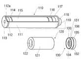
도 1은 본 고안의 제 1 실시예에 따른 액체 기화 흡입 장치가 결합된 모습을 보이는 사시도이고, 도 2는 본 고안의 제 1 실시예에 따른 액체 기화 흡입 장치가 분리된 모습을 보이는 사시도이고, 도 3은 본 고안의 제 1 실시예에 따른 액체 기화 흡입 장치에 적용되는 제 2 부재 및 뚜껑의 내부 구성을 보이는 단면도이다.1 is a perspective view showing the liquid vaporization suction device according to the first embodiment of the present invention is coupled, Figure 2 is a perspective view showing the liquid vaporization suction device according to the first embodiment of the present invention is separated, 3 is a cross-sectional view showing the internal configuration of the second member and the lid applied to the liquid vaporization suction apparatus according to the first embodiment of the present invention.
도 1 내지 도 3을 함께 참조하면, 본 실시예에 따른 액체 기화 흡입 장치(100)는 제 1 부재(110)와, 제 2 부재(120)를 포함한다.1 to 3 together, the liquid
상기 제 1 부재(110)의 케이스(111) 내에는 발광 다이오드(114), 배터리(115), 제어부(116) 및 흡입 감지 스위치(117)가 순차적으로 배치된다.The
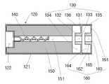
상기 제 2 부재(120)의 케이스(121) 내에는 필터(150)와, 발열 부재(140)가 배치된다. 상기 제 2 부재(120)의 말단, 즉 사용자의 입 내에 위치되는 말단에는 뚜껑(130)이 연결된다.The
상기 발광 다이오드(114)는 상기 배터리(115)에 전기적으로 연결되어, 상기 제어부(116)의 제어에 따라 붉은 색으로 발광할 수 있는 부분이다. 상기 발광 다이오드(114)의 붉은 빛이 외부에서도 인지될 수 있도록, 상기 케이스(111)의 전면을 이루는 전면 부재(112)에는 투명창(113)이 형성된다.The
상기 전면 부재(112)에는 관통 홀(112a)이 형성되는데, 사용자가 상기 액체 기화 흡입 장치(100)를 물고 흡입을 하면, 이러한 관통 홀(112a)을 통해 외부의 공기가 상기 액체 기화 흡입 장치(100) 내부로 유입될 수 있다.A through
상기 배터리(115)는 상기 발광 다이오드(114), 상기 제어부(116), 상기 발열 부재(140) 등에 전원을 인가하는 부분으로, 폴리머 리튬 전지 등이 제시될 수 있다.The
상기 제어부(116)는 상기 액체 기화 흡입 장치(100)의 작동을 위해 요구되는 각종 회로가 형성된 부분이다. 이러한 제어부(116)는 상기 흡임 감지 스위치(117)에서 전달된 감지값에 따라 상기 발광 다이오드(114), 상기 발열 부재(140) 등의 작동을 제어할 수 있다.The
상기 흡입 감지 스위치(117)는 사용자가 상기 제 2 부재(120)의 말단부를 입 으로 물고 흡입을 할 때, 그러한 흡입 여부를 감지하는 부분이다.The
도면 번호 118은 상기 제 1 부재(110)의 케이스(111)의 후면에 배치되는 후면 부재이고, 도면 번호 119는 상기 후면 부재(118)로부터 돌출되는 결합 돌기이다.
상기 결합 돌기(119)는 상기 제 2 부재(120)의 케이스(121)의 전면에 형성된 결합 홈(122)에 결합되는 부분이다. 상기 결합 돌기(119)가 상기 결합 홈(122)에 결합되면, 상기 제 1 부재(110)와 상기 제 2 부재(120)가 연결된다. 이러한 결합이 더욱 견고하게 이루어질 수 있도록, 상기 결합 돌기(119)와 상기 결합 홈(122)에는 서로 맞물리는 나사산 및 나사홈이 형성될 수 있다.The
상기 결합 돌기(119)는 상기 배터리(115) 및 상기 제어부(116)와 전기적으로 연결되고, 상기 결합 홈(122)은 상기 발열 부재(140)와 전기적으로 연결되어, 상기 결합 돌기(119)가 상기 결합 홈(122)에 결합되면, 상기 배터리(115) 및 상기 제어부(116)와 상기 발열 부재(140)가 전기적으로 연결될 수 있다.The
상기 필터(150)는 상기 제 2 부재(120)의 케이스(121) 내에 수용되는 것으로, 니코틴 액을 함유하는 부분이다. 보다 많은 니코틴 액이 수용될 수 있도록, 상기 필터(150)는 상기 제 2 부재(120)의 케이스(121) 내에 가득 차도록 형성될 수 있다.The
상기 필터(150) 내부에는 관통 홀(151)이 형성된다. 상기 관통 홀(151)의 전측은 상기 결합 홈(122)에 연통되어 있고, 그 후측은 후술되는 뚜껑(130)의 관통 홀(133)에 연통되어 있다. 따라서, 상기 제 1 부재(110)에 형성된 상기 관통 홀(112a)을 통해 유입된 공기는 상기 제 1 부재(110)의 케이스(111) 내부를 따라 유동되어, 상기 결합 홈(122) 및 상기 필터(150) 내의 상기 관통 홀(151)을 거쳐 상기 제 2 부재(120) 내부를 경유할 수 있다.The through
상기와 같이 공기가 상기 필터(150) 내의 상기 관통 홀(151)을 경유하는 동안, 그러한 공기에는 상기 발열 부재(140)에 의해 기화된 니코틴이 함유된다.While air passes through the through
상기 필터(150)는 니코틴 액을 함유한 얇은 면상체가 상기 발열 부재(140) 주변을 감는 형태로 형성될 수 있다.The
상기 발열 부재(140)는 상기 제어부(116)의 명령에 따라 상기 배터리(115)로부터 전원을 공급받아 발열할 수 있는 부분이다. 상기 발열 부재(140)가 발열하면, 그 열에 의해 상기 필터(150) 내의 니코틴 액이 기화되어 연기가 발생될 수 있다.The
상기 발열 부재(140)의 일 측 말단은 상기 결합 홈(122)에 전기적 및 물리적으로 연결되고, 그 타 측 말단은 상기 제 2 부재(120)의 케이스(121) 내부로 연장된 형상을 이룬다.One end of the
본 실시예에서는, 상기 필터(150)가 상기 제 2 부재(120)의 케이스(121) 내에서 상기 발열 부재(140)를 감싸도록 배치된다. 그러면, 상기 발열 부재(140)가 상기 필터(150) 내에 함유된 니코틴 액을 직접 가열하여 연기를 형성할 수 있다. 따라서, 종래에 각각 별도로 구성했던 필터 케이스, 액체 유도체 지지 부재 등의 구조체가 생략될 수 있으므로, 상기 액체 기화 흡입 장치(100)의 구조가 간단해지고, 그 크기가 컴팩트해질 수 있다. 그리고, 종래의 필터 케이스, 액체 유도체 지지 부재 등의 구조체가 생략된 체적만큼 상기 제 2 부재(120)의 케이스(121) 내에 상기 필터(150)를 채울 수 있으므로, 상대적으로 더 많은 양의 니코틴 액을 수용할 수 있게 된다.In the present embodiment, the
상기 필터(150)에 함유된 니코틴 액이 모두 소진되면, 상기 제 2 부재(120)를 상기 제 1 부재(110)로부터 분리하여, 새로운 제 2 부재(120)로 교환할 수 있다. 그러면, 장시간 사용에 따라 상기 발열 부재(140)가 니코틴 등 불순물에 의해 오염되는 현상을 방지할 수 있다.When the nicotine liquid contained in the
상기 필터(150)의 재질로는 솜 등 다양한 물질이 제시될 수 있다. 그 중 상기 필터(150)의 재질로 니코틴 액을 함유할 수 있고 비가연성인 물질이 제시될 수 있는데, 이러한 물질이 적용되면, 상기 발열 부재(140)에 의해 상기 필터(150)가 타지 않으면서도, 상기 필터(150) 내에 안정적으로 니코틴 액을 함유할 수 있게 된다.As the material of the
상기 뚜껑(130)은 상기 제 2 부재(120)의 말단에 배치된 것으로, 상기 뚜껑(130)의 몸체(131)에는 관통 홀(133)과, 함몰 홈(134)이 형성된다. 상기 뚜껑(130)에는 응집체 수용 부재(160)가 더 결합될 수 있다. 상기 응집체 수용 부재(160)의 몸체(161)에도 상기 뚜껑(130)의 관통 홀(133) 및 함몰 홈(134)과 대응되는 관통 홀(163) 및 함몰 홈(164)이 형성된다.The
상기 뚜껑(130)의 몸체(131) 전단에는 상기 제 2 부재(120)의 케이스(121)에 삽입되는 삽입체(136)가 형성되고, 상기 뚜껑(130)의 몸체(131) 후단에는 상기 응집체 수용 부재(160)가 삽입되는 공간을 형성하는 삽입 홀부(135)가 형성된다.An
상기 삽입 홀부(135)에 상기 응집체 수용 부재(160)의 삽입체(165)가 삽입되 면, 상기 뚜껑(130)과 상기 응집체 수용 부재(160)가 일체를 이루게 된다. 그리고, 상기 제 2 부재(120)의 케이스(121) 후단에 상기 뚜껑(130)의 삽입체(136)가 삽입되면, 상기 뚜껑(130) 및 상기 응집체 수용 부재(160)가 상기 제 2 부재(120)와 일체를 이루게 된다.When the
상기 관통 홀(133, 163)은 각각 상기 뚜껑(130)의 몸체(131) 및 상기 응집체 수용 부재(160)의 몸체(161)를 각각 관통한 것으로, 상기 관통 홀(133, 163)을 통해 상기 액체 기화 흡입 장치(100)를 물고 있는 사용자의 입 내부로 상기 제 2 부재(120) 내에서 발생된 연기가 유출될 수 있다. 상기 연기는 상기 필터(150)의 관통 홀(151) 내부로 유입된 공기에 상기 발열 부재(140)에 의해 기화된 니코틴이 함유된 상태의 물질이다.The through
상기 함몰 홈(134, 164)은 상기 관통 홀(133, 163)의 주변 부분(132, 162)에 형성된 것으로, 상기 관통 홀(133, 163) 주변으로 이동된 연기 중의 니코틴 액의 응집체를 수용하는 부분이다. 즉, 상기 관통 홀(133, 163)을 통해 연기가 유출되는 과정에서, 일부 니코틴 액이 응집되어 응집체를 이룰 수 있는데, 이러한 니코틴 액 응집체가 상기 함몰 홈(134, 164)에 수용될 수 있다.The recessed
상기 함몰 홈(134, 164)은 상기 필터(150)와 인접해 있어서, 상기 함몰 홈(134)에 수용된 니코틴 액 응집체는 상기 필터(150)로 환원될 수 있다. 따라서, 니코틴 액의 불필요한 낭비가 최소화될 수 있고, 상기 니코틴 액 응집체가 그대로 상기 관통 홀(133, 163)을 통해 유출되어 사용자에게 불쾌감을 초래하는 현상을 방지할 수 있다.The recessed
또한, 상기 뚜껑(130) 및 상기 응집체 수용 부재(160)에 각각 상기 함몰 홈(134, 164)이 형성됨에 따라, 연기의 유동 경로를 따라 이중으로 상기 니코틴 액 응집체의 수집이 이루어질 수 있다. 따라서, 니코틴 액의 낭비 방지 및 니코틴 액 응집체 외부 유출 방지 효과가 배가될 수 있다.In addition, as the recessed
상기 니코틴 액 응집체가 원활하게 수용되도록, 상기 함몰 홈(134, 164)은 상기 관통 홀(133, 163) 주변을 따라 형성될 수 있다.The recessed
여기서, 본 실시예에서는 상기 뚜껑(130) 및 상기 응집체 수용 부재(160)가 모두 적용되는 것으로 제시되나, 이는 예시적인 것으로, 더 많은 개수의 응집체 수용 부재가 적용될 수도 있고, 상기 응집체 수용 부재(160)의 적용없이 상기 뚜껑(130)만 적용될 수도 있다.Here, in the present embodiment, it is shown that both the
이하에서는 상기와 같이 구성된 액체 기화 흡입 장치(100)의 작동에 대하여 간단히 설명한다.Hereinafter, the operation of the liquid
먼저, 사용자가 상기 액체 기화 흡입 장치(100)를 입에 물고 흡입을 하면, 상기 흡입 감지 스위치(117)가 이를 감지하고, 상기 제어부(116)에 해당 감지값을 전달한다.First, when the user inhales the liquid
상기 감지값을 전달받은 상기 제어부(116)는 상기 발광 다이오드(114) 및 상기 발열 부재(140)에 작동 명령을 전달하고, 그에 따라 상기 발광 다이오드(114) 및 상기 발열 부재(140)는 상기 배터리(115)의 전원을 공급받아 각각 발광 및 발열을 하게 된다.The
상기 발열 부재(140)가 발열되면, 그 열에 의해 상기 필터(150) 내의 니코틴 액이 기화되어 연기가 형성된다. 상기와 같이 형성된 연기는 상기 관통 홀(133,163)을 통해 사용자의 입 내부로 유출된다.When the
상기와 같은 액체 기화 흡입 장치(100)의 작동에 의해, 사용자는 실제 담배를 피우는 것과 유사한 느낌을 얻게 된다.By the operation of the liquid
이하에서는 도면을 참조하여 본 고안의 제 2 실시예에 대하여 설명한다. 이러한 설명을 수행함에 있어서 상기된 본 고안의 제 1 실시예에서 이미 기재된 내용과 중복되는 설명은 그에 갈음하고, 여기서는 생략하기로 한다.Hereinafter, a second embodiment of the present invention will be described with reference to the drawings. In carrying out this description, descriptions overlapping with those already described in the above-described first embodiment of the present invention will be replaced with the description thereof and will be omitted herein.
도 4는 본 고안의 제 2 실시예에 따른 액체 기화 흡입 장치에 적용되는 제 2 부재, 뚜껑 및 응집체 수용 부재의 내부 구성을 보이는 단면도이다.Figure 4 is a cross-sectional view showing the internal configuration of the second member, the lid and the aggregate receiving member applied to the liquid vaporization suction device according to a second embodiment of the present invention.
도 4를 참조하면, 본 실시예에서는 제 2 부재(220)의 케이스(221) 내에 발열 부재(240)가 삽입되는 발열 부재 수용부(270)가 더 배치된다. 상기 발열 부재 수용부(270)의 내벽과 상기 발열 부재(240)는 비접촉식으로 이격되도록 배치될 수 있다.Referring to FIG. 4, the heat generating
상기 발열 부재 수용부(270)에 상기 발열 부재(240)가 삽입됨에 따라, 필터(250)와 상기 발열 부재(240)가 직접 접촉되지 아니할 수 있다. 따라서, 상기 필터(250)가 비가연성 물질이 아니더라도, 상기 발열 부재(240)에 의해 상기 필터(250)가 타는 현상이 방지될 수 있다.As the
상기 발열 부재(240)의 열이 상기 필터(250)로 원활하게 전달될 수 있도록, 상기 발열 부재 수용부(270)는 망 형상으로 이루어질 수 있다.The heat generating
도 5는 본 고안의 제 3 실시예에 따른 액체 기화 흡입 장치에 적용되는 제 2 부재, 뚜껑 및 응집체 수용 부재의 내부 구성을 보이는 단면도이고, 도 6은 본 고안의 제 3 실시예에 따른 액체 기화 흡입 장치에 적용되는 뚜껑을 후면을 보이는 도면이다.Figure 5 is a cross-sectional view showing the internal configuration of the second member, the lid and the aggregate receiving member applied to the liquid vaporization suction device according to a third embodiment of the present invention, Figure 6 is a liquid vaporization according to a third embodiment of the present invention The figure shows the back of the lid applied to the suction device.
도 5 및 도 6을 함께 참조하면, 본 실시예에서는 뚜껑(330)이 제 2 부재(320)와 일체로 성형된다. 그리고, 상기 뚜껑(330)의 말단에는 상기 제 2 부재(320)의 케이스(321)가 후측으로 연장된 형태의 삽입 홀부(335)가 형성되어, 상기 삽입 홀부(335)에 응집체 수집 부재(360)가 결합될 수 있다.5 and 6 together, in this embodiment, the
상기 뚜껑(330)에는 연기가 관통되는 관통 홀(333) 이외에 리필 홀(336)이 더 형성된다. 상기 리필 홀(336)은 상기 뚜껑(330)을 관통한 형태를 이루고, 함몰 홈(334)의 크기가 최대화될 수 있도록 상기 뚜껑(330)의 가장자리에 형성될 수 있다.The
상기 리필 홀(336)은 일체로 성형된 상기 뚜껑(330) 및 상기 제 2 부재(320) 내부에 삽입된 필터(350)에 니코틴 액을 보충하기 위한 것이다. 상기 리필 홀(333)을 이루는 부분은 상기 필터(350)에 맞닿는 형태를 이룰 수 있다.The
상기와 같이, 상기 뚜껑(330)에 상기 리필 홀(336)이 형성됨에 따라, 일체로 성형된 상기 뚜껑(330) 및 상기 제 2 부재(320) 내부에 삽입된 상기 필터(350)에 니코틴 액을 용이하게 보충할 수 있다.As described above, as the
상기 리필 홀(336)의 입구 부분에는 경사면(337)이 형성될 수 있다. 이러한 경사면(337)이 형성됨에 따라, 상기 리필 홀(336)의 입구 부분이 깔때기 형상을 이룰 수 있어서, 니코틴 액의 보충 작업이 손쉽게 이루어질 수 있다.An
상기 응집체 수집 부재(360)의 가장자리 중 일부(366)는 상기 리필 홀(336)을 막는 마개가 될 수 있다. 그러면, 평소 상기 리필 홀(336)은 막혀 있어서 외부의 이물질 침투가 방지되고 상기 필터(350)의 니코틴 액의 유출이 방지될 수 있고, 니코틴 액의 보충이 요구되는 경우, 사용자가 상기 응집체 수집 부재(360)를 제거한 다음, 상기 리필 홀(336)을 통해 니코틴 액을 손쉽게 보충할 수 있다.A
상기에서 본 고안은 특정한 실시예에 관하여 도시되고 설명되었지만, 당업계에서 통상의 지식을 가진 자라면 이하의 특허청구범위에 기재된 본 고안의 사상 및 영역을 벗어나지 않는 범위 내에서 본 고안을 다양하게 수정 및 변경시킬 수 있음을 알 수 있을 것이다. 그렇지만 이러한 수정 및 변형 구조들은 모두 본 고안의 권리범위 내에 포함되는 것임을 분명하게 밝혀두고자 한다.While the present invention has been shown and described with respect to specific embodiments, those skilled in the art can variously modify the present invention without departing from the spirit and scope of the present invention as set forth in the claims below. And that it can be changed. Nevertheless, it is intended to be clear that all such modifications and variations are included within the scope of the present invention.
본 고안의 일 측면에 따른 액체 기화 흡입 장치에 의하면, 그 구조가 간단해지고, 그 크기가 컴팩트해질 수 있으며, 필터 후측의 뚜껑 부분에 응집된 액체를 필터로 환원시킬 수 있으므로, 그 산업상 이용 가능성이 높다고 하겠다.According to the liquid vaporization suction device according to an aspect of the present invention, the structure is simple, the size can be compact, and the liquid agglomerated in the lid portion at the rear of the filter can be reduced to the filter, the industrial applicability This is high.
도 1은 본 고안의 제 1 실시예에 따른 액체 기화 흡입 장치가 결합된 모습을 보이는 사시도.1 is a perspective view showing a state in which the liquid vaporization suction device according to the first embodiment of the present invention is coupled.
도 2는 본 고안의 제 1 실시예에 따른 액체 기화 흡입 장치가 분리된 모습을 보이는 사시도.Figure 2 is a perspective view showing a state in which the liquid vaporization suction device according to the first embodiment of the present invention is separated.
도 3은 본 고안의 제 1 실시예에 따른 액체 기화 흡입 장치에 적용되는 제 2 부재 및 뚜껑의 내부 구성을 보이는 단면도.Figure 3 is a cross-sectional view showing the internal configuration of the second member and the lid applied to the liquid vaporization suction apparatus according to the first embodiment of the present invention.
도 4는 본 고안의 제 2 실시예에 따른 액체 기화 흡입 장치에 적용되는 제 2 부재, 뚜껑 및 응집체 수용 부재의 내부 구성을 보이는 단면도.Figure 4 is a cross-sectional view showing the internal configuration of the second member, the lid and the aggregate receiving member applied to the liquid vaporization suction device according to a second embodiment of the present invention.
도 5는 본 고안의 제 3 실시예에 따른 액체 기화 흡입 장치에 적용되는 제 2 부재, 뚜껑 및 응집체 수용 부재의 내부 구성을 보이는 단면도.5 is a cross-sectional view showing the internal configuration of the second member, the lid and the aggregate receiving member applied to the liquid vaporization suction apparatus according to the third embodiment of the present invention.
도 6은 본 고안의 제 3 실시예에 따른 액체 기화 흡입 장치에 적용되는 뚜껑을 후면을 보이는 도면.Figure 6 is a view showing the back of the lid applied to the liquid vaporization suction apparatus according to a third embodiment of the present invention.
Claims (7)
Translated fromKoreanPriority Applications (1)
| Application Number | Priority Date | Filing Date | Title |
|---|---|---|---|
| KR2020080017380UKR20100006995U (en) | 2008-12-30 | 2008-12-30 | Liquid vaporizing and inhaling apparatus |
Applications Claiming Priority (1)
| Application Number | Priority Date | Filing Date | Title |
|---|---|---|---|
| KR2020080017380UKR20100006995U (en) | 2008-12-30 | 2008-12-30 | Liquid vaporizing and inhaling apparatus |
Related Child Applications (1)
| Application Number | Title | Priority Date | Filing Date |
|---|---|---|---|
| KR1020110053556ADivisionKR101165778B1 (en) | 2011-06-02 | 2011-06-02 | Liquid vaporizing and inhaling apparatus |
Publications (1)
| Publication Number | Publication Date |
|---|---|
| KR20100006995Utrue KR20100006995U (en) | 2010-07-08 |
Family
ID=44452400
Family Applications (1)
| Application Number | Title | Priority Date | Filing Date |
|---|---|---|---|
| KR2020080017380UWithdrawnKR20100006995U (en) | 2008-12-30 | 2008-12-30 | Liquid vaporizing and inhaling apparatus |
Country Status (1)
| Country | Link |
|---|---|
| KR (1) | KR20100006995U (en) |
Cited By (9)
| Publication number | Priority date | Publication date | Assignee | Title |
|---|---|---|---|---|
| US10368582B2 (en) | 2012-07-16 | 2019-08-06 | Nicoventures Holdings Limited | Electronic vapor provision device |
| US11083856B2 (en) | 2014-12-11 | 2021-08-10 | Nicoventures Trading Limited | Aerosol provision systems |
| US11253671B2 (en) | 2011-07-27 | 2022-02-22 | Nicoventures Trading Limited | Inhaler component |
| US11744964B2 (en) | 2016-04-27 | 2023-09-05 | Nicoventures Trading Limited | Electronic aerosol provision system and vaporizer therefor |
| US11758936B2 (en) | 2006-10-18 | 2023-09-19 | Rai Strategic Holdings, Inc. | Tobacco-containing smoking article |
| US11779051B2 (en) | 2011-08-09 | 2023-10-10 | Rai Strategic Holdings, Inc. | Smoking articles and use thereof for yielding inhalation materials |
| US11864584B2 (en) | 2014-02-28 | 2024-01-09 | Rai Strategic Holdings, Inc. | Control body for an electronic smoking article |
| US12089640B2 (en) | 2011-02-11 | 2024-09-17 | Nicoventures Trading Limited | Inhaler component |
| US12274824B2 (en) | 2015-10-01 | 2025-04-15 | Nicoventures Trading Limited | Aerosol provision system |
- 2008
- 2008-12-30KRKR2020080017380Upatent/KR20100006995U/ennot_activeWithdrawn
Cited By (17)
| Publication number | Priority date | Publication date | Assignee | Title |
|---|---|---|---|---|
| US11986009B2 (en) | 2006-10-18 | 2024-05-21 | Rai Strategic Holdings, Inc. | Tobacco-containing smoking article |
| US11758936B2 (en) | 2006-10-18 | 2023-09-19 | Rai Strategic Holdings, Inc. | Tobacco-containing smoking article |
| US11925202B2 (en) | 2006-10-18 | 2024-03-12 | Rai Strategic Holdings, Inc. | Tobacco-containing smoking article |
| US11805806B2 (en) | 2006-10-18 | 2023-11-07 | Rai Strategic Holdings, Inc. | Tobacco-containing smoking article |
| US11980220B2 (en) | 2006-10-18 | 2024-05-14 | Rai Strategic Holdings, Inc. | Tobacco-containing smoking article |
| US12089640B2 (en) | 2011-02-11 | 2024-09-17 | Nicoventures Trading Limited | Inhaler component |
| US11253671B2 (en) | 2011-07-27 | 2022-02-22 | Nicoventures Trading Limited | Inhaler component |
| US12016384B2 (en) | 2011-08-09 | 2024-06-25 | Rai Strategic Holdings, Inc. | Smoking articles and use thereof for yielding inhalation materials |
| US11779051B2 (en) | 2011-08-09 | 2023-10-10 | Rai Strategic Holdings, Inc. | Smoking articles and use thereof for yielding inhalation materials |
| US10368582B2 (en) | 2012-07-16 | 2019-08-06 | Nicoventures Holdings Limited | Electronic vapor provision device |
| US11039643B2 (en) | 2012-07-16 | 2021-06-22 | Nicoventures Trading Limited | Electronic vapor provision device |
| US11039647B2 (en) | 2012-07-16 | 2021-06-22 | Nicoventures Trading Limited | Electronic vapor provision device |
| US11864584B2 (en) | 2014-02-28 | 2024-01-09 | Rai Strategic Holdings, Inc. | Control body for an electronic smoking article |
| US11083856B2 (en) | 2014-12-11 | 2021-08-10 | Nicoventures Trading Limited | Aerosol provision systems |
| US12357777B2 (en) | 2014-12-11 | 2025-07-15 | Nicoventures Trading Limited | Aerosol provision systems |
| US12274824B2 (en) | 2015-10-01 | 2025-04-15 | Nicoventures Trading Limited | Aerosol provision system |
| US11744964B2 (en) | 2016-04-27 | 2023-09-05 | Nicoventures Trading Limited | Electronic aerosol provision system and vaporizer therefor |
Similar Documents
| Publication | Publication Date | Title |
|---|---|---|
| KR20100006995U (en) | Liquid vaporizing and inhaling apparatus | |
| EP3793383B1 (en) | A consumable for a smoking substitute device | |
| KR200470732Y1 (en) | Vaporizing and inhaling apparatus and vaporizing member applied the vaporizing and inhaling apparatus | |
| KR20120098343A (en) | Electronic cigarette | |
| KR200448259Y1 (en) | Electronic cigarette | |
| KR101165772B1 (en) | Liquid vaporizing and inhaling apparatus | |
| KR200452359Y1 (en) | Electronic cigarette | |
| US20220218022A1 (en) | Smoking substitute component | |
| JPWO2018016030A1 (en) | Heating type flavor suction tool | |
| KR20220013119A (en) | Drip stick and Cartridge for liquid type electric cigarette | |
| KR101193644B1 (en) | Vaporizing and inhaling apparatus | |
| KR20200005159A (en) | Cigarette type electronic cigarette | |
| KR101165778B1 (en) | Liquid vaporizing and inhaling apparatus | |
| EP3787427B1 (en) | Smoking substitute device having a liquid impermeable filter between the mouthpiece and the liquid tank | |
| KR20120109256A (en) | Cartridge and electronic cigaret including the same | |
| KR20090003871U (en) | Liquid vaporization suction device | |
| JP2023518888A (en) | Cartridges containing nicotine | |
| EP4208054B1 (en) | Cartomizer for an aerosol generating device with leakage prevention | |
| KR20110079587A (en) | Liquid vaporization suction device including cloud protection | |
| KR200455132Y1 (en) | Liquid vaporization suction device | |
| KR101269246B1 (en) | Vaporizing and inhaling apparatus | |
| KR200467156Y1 (en) | Liquid vaporization suction device | |
| KR101162683B1 (en) | Liquid vaporizing and inhaling apparatus | |
| KR102175704B1 (en) | Smoking habit reformation device with liquid inflow preventing member | |
| US12239162B2 (en) | Smoking substitute component |
Legal Events
| Date | Code | Title | Description |
|---|---|---|---|
| A201 | Request for examination | ||
| UA0108 | Application for utility model registration | Comment text:Application for Utility Model Registration Patent event code:UA01011R08D Patent event date:20081230 | |
| UA0201 | Request for examination | ||
| UG1501 | Laying open of application | ||
| E902 | Notification of reason for refusal | ||
| UE0902 | Notice of grounds for rejection | Comment text:Notification of reason for refusal Patent event code:UE09021S01D Patent event date:20110323 | |
| U125 | Withdrawal of application by converted application | ||
| UC1205 | Withdrawal of application by converted application |