KR20100003624A - Novel condensed carbazole derivatives and organic electroluminescent device comprising same - Google Patents
Novel condensed carbazole derivatives and organic electroluminescent device comprising sameDownload PDFInfo
- Publication number
- KR20100003624A KR20100003624AKR1020080063612AKR20080063612AKR20100003624AKR 20100003624 AKR20100003624 AKR 20100003624AKR 1020080063612 AKR1020080063612 AKR 1020080063612AKR 20080063612 AKR20080063612 AKR 20080063612AKR 20100003624 AKR20100003624 AKR 20100003624A
- Authority
- KR
- South Korea
- Prior art keywords
- organic electroluminescent
- group
- electroluminescent device
- transport layer
- layer
- Prior art date
- Legal status (The legal status is an assumption and is not a legal conclusion. Google has not performed a legal analysis and makes no representation as to the accuracy of the status listed.)
- Granted
Links
- ZZAFQAIDEJLUGL-UHFFFAOYSA-NCC(C)(c1c2)c3cc(Br)ccc3-c1cc([n](c1c3)-c4ccccc4)c2c1cc(C1(C)C)c3-c(cc2)c1cc2BrChemical compoundCC(C)(c1c2)c3cc(Br)ccc3-c1cc([n](c1c3)-c4ccccc4)c2c1cc(C1(C)C)c3-c(cc2)c1cc2BrZZAFQAIDEJLUGL-UHFFFAOYSA-N0.000description1
- QABXDXTXILKUGG-UHFFFAOYSA-NCC(C)(c1c2)c3cc(N(c4ccccc4)c4cccc5c4cccc5)ccc3-c1cc([n](c1c3)-c4ccccc4)c2c1cc(C(C)(C)c1c2)c3-c1ccc2N(c1ccccc1)c1c(cccc2)c2ccc1Chemical compoundCC(C)(c1c2)c3cc(N(c4ccccc4)c4cccc5c4cccc5)ccc3-c1cc([n](c1c3)-c4ccccc4)c2c1cc(C(C)(C)c1c2)c3-c1ccc2N(c1ccccc1)c1c(cccc2)c2ccc1QABXDXTXILKUGG-UHFFFAOYSA-N0.000description1
- XQVWYOYUZDUNRW-UHFFFAOYSA-Nc(cc1)ccc1Nc1cccc2c1cccc2Chemical compoundc(cc1)ccc1Nc1cccc2c1cccc2XQVWYOYUZDUNRW-UHFFFAOYSA-N0.000description1
Images


Classifications
- C—CHEMISTRY; METALLURGY
- C07—ORGANIC CHEMISTRY
- C07D—HETEROCYCLIC COMPOUNDS
- C07D209/00—Heterocyclic compounds containing five-membered rings, condensed with other rings, with one nitrogen atom as the only ring hetero atom
- C07D209/56—Ring systems containing three or more rings
- C07D209/80—[b, c]- or [b, d]-condensed
- C07D209/94—[b, c]- or [b, d]-condensed containing carbocyclic rings other than six-membered
- C—CHEMISTRY; METALLURGY
- C07—ORGANIC CHEMISTRY
- C07D—HETEROCYCLIC COMPOUNDS
- C07D209/00—Heterocyclic compounds containing five-membered rings, condensed with other rings, with one nitrogen atom as the only ring hetero atom
- C07D209/56—Ring systems containing three or more rings
- C07D209/96—Spiro-condensed ring systems
- H—ELECTRICITY
- H10—SEMICONDUCTOR DEVICES; ELECTRIC SOLID-STATE DEVICES NOT OTHERWISE PROVIDED FOR
- H10K—ORGANIC ELECTRIC SOLID-STATE DEVICES
- H10K50/00—Organic light-emitting devices
- H10K50/10—OLEDs or polymer light-emitting diodes [PLED]
- H10K50/14—Carrier transporting layers
- H10K50/15—Hole transporting layers
- H—ELECTRICITY
- H10—SEMICONDUCTOR DEVICES; ELECTRIC SOLID-STATE DEVICES NOT OTHERWISE PROVIDED FOR
- H10K—ORGANIC ELECTRIC SOLID-STATE DEVICES
- H10K50/00—Organic light-emitting devices
- H10K50/10—OLEDs or polymer light-emitting diodes [PLED]
- H10K50/17—Carrier injection layers
- H—ELECTRICITY
- H10—SEMICONDUCTOR DEVICES; ELECTRIC SOLID-STATE DEVICES NOT OTHERWISE PROVIDED FOR
- H10K—ORGANIC ELECTRIC SOLID-STATE DEVICES
- H10K85/00—Organic materials used in the body or electrodes of devices covered by this subclass
- H10K85/60—Organic compounds having low molecular weight
- H10K85/631—Amine compounds having at least two aryl rest on at least one amine-nitrogen atom, e.g. triphenylamine
- H10K85/636—Amine compounds having at least two aryl rest on at least one amine-nitrogen atom, e.g. triphenylamine comprising heteroaromatic hydrocarbons as substituents on the nitrogen atom
- H—ELECTRICITY
- H10—SEMICONDUCTOR DEVICES; ELECTRIC SOLID-STATE DEVICES NOT OTHERWISE PROVIDED FOR
- H10K—ORGANIC ELECTRIC SOLID-STATE DEVICES
- H10K85/00—Organic materials used in the body or electrodes of devices covered by this subclass
- H10K85/60—Organic compounds having low molecular weight
- H10K85/649—Aromatic compounds comprising a hetero atom
- H10K85/657—Polycyclic condensed heteroaromatic hydrocarbons
- H10K85/6572—Polycyclic condensed heteroaromatic hydrocarbons comprising only nitrogen in the heteroaromatic polycondensed ring system, e.g. phenanthroline or carbazole
Landscapes
- Chemical & Material Sciences (AREA)
- Organic Chemistry (AREA)
- Physics & Mathematics (AREA)
- Optics & Photonics (AREA)
- Spectroscopy & Molecular Physics (AREA)
- Engineering & Computer Science (AREA)
- Materials Engineering (AREA)
- Electroluminescent Light Sources (AREA)
Abstract
Translated fromKoreanDescription
Translated fromKorean본 발명은 신규의 축합 카바졸 유도체 및 이를 정공주입층 및/또는 정공수송층 물질로서 포함하는 유기 전계발광 소자에 관한 것이다.The present invention relates to novel condensed carbazole derivatives and organic electroluminescent devices comprising them as hole injection and / or hole transport layer materials.
최근, 자체 발광형으로 저전압 구동이 가능한 유기 전계발광 소자는, 평판 표시소자의 주류인 액정디스플레이(LCD, liquid crystal display)에 비해, 시야각, 대조비 등이 우수하고 백라이트가 불필요하여 경량 및 박형이 가능하며 소비전력 측면에서도 유리하고 색 재현 범위가 넓어, 차세대 표시소자로서 주목을 받고 있다.In recent years, organic electroluminescent devices capable of low-voltage driving with self-luminous type have superior viewing angles, contrast ratios, and the like and are lighter and thinner than the liquid crystal display (LCD), which is the mainstream of flat panel display devices. It is also attracting attention as a next-generation display device because it is advantageous in terms of power consumption and has a wide range of color reproduction.
일반적으로, 유기 전계발광 소자는 음극(전자주입전극)과 양극(정공주입전극), 및 상기 두 전극 사이에 유기층을 포함하는 구조를 갖는다. 이때, 유기층은 발광층(EML, light emitting layer) 이외에, 정공주입층(HIL, hole injection layer), 정공수송층(HTL, hole transport layer), 전자수송층(ETL, electron transport layer) 및/또는 전자주입층(EIL, electron injection layer)을 포함할 수 있으며, 발광층의 발광특성상, 전자차단층(EBL, electron blocking layer) 또는 정공차단층(HBL, hole blocking layer)을 추가로 포함할 수 있다. 양극/정공주입층/정공수송층/발광층/정공차단층/전자수송층/전자주입층/음극 순으로 적층된 구조를 갖는 일반적인 유기 전계발광 소자의 구조를 도 1에 나타내었다.In general, an organic electroluminescent device has a structure including a cathode (electron injection electrode) and an anode (hole injection electrode), and an organic layer between the two electrodes. In this case, the organic layer may be a hole injection layer (HIL), a hole transport layer (HTL), an electron transport layer (ETL) and / or an electron injection layer, in addition to the light emitting layer (EML). And an electron injection layer (EIL), and may further include an electron blocking layer (EBL) or a hole blocking layer (HBL) due to light emission characteristics of the light emitting layer. A structure of a general organic electroluminescent device having a structure stacked in the order of an anode / hole injection layer / hole transport layer / light emitting layer / hole blocking layer / electron transport layer / electron injection layer / cathode is shown in FIG. 1.
이러한 구조의 유기 전계발광 소자에 전기장이 가해지면, 양극으로부터 정공이 주입되고, 음극으로부터 전자가 주입되어, 정공과 전자는 각각 정공수송층과 전자수송층을 거쳐 발광층에서 재조합(recombination)하게 되어 발광여기자(exitons)를 형성한다. 형성된 발광여기자는 바닥상태(ground states)로 전이하면서 빛을 방출한다. 발광 상태의 효율과 안정성을 증가시키기 위하여, 발광 색소(도펀트)를 발광층(호스트)에 도핑하기도 한다.When an electric field is applied to the organic electroluminescent device having such a structure, holes are injected from the anode, electrons are injected from the cathode, and holes and electrons are recombined in the emission layer through the hole transport layer and the electron transport layer, respectively, thereby emitting light. form exitons). The formed light exciton emits light as it transitions to ground states. In order to increase the efficiency and stability of the light emitting state, a light emitting dye (dopant) may be doped into the light emitting layer (host).
유기 전계발광 소자의 정공주입층 및/또는 정공수송층에 사용되는 물질로서 카바졸 유도체가 다양하게 알려져 있다 (미국특허 제6,979,414호, 미국특허 제6,670,054호, 미국특허 제6,660,410호, 미국특허 제5,591,554호, 미국특허 제4,521,605호, 대한민국특허 제351234호, 대한민국특허 제346984호 참조).Carbazole derivatives are variously known as materials used in the hole injection layer and / or the hole transport layer of the organic electroluminescent device (US Pat. No. 6,979,414, US Pat. , US Patent No. 4,521,605, Republic of Korea Patent No. 351234, Republic of Korea Patent No. 346984).
그러나, 이제까지 알려진 카바졸 유도체를 포함하는 정공주입층 및/또는 정공수송층을 이용한 유기 전계발광 소자의 경우 높은 구동전압, 낮은 효율 및 짧은 수명으로 인해 실용화하는 데에 많은 어려움이 있었다. 따라서, 카바졸 유도체를 이용한 다양한 종류의 정공주입층 또는 정공수송층 물질을 이용하여 저전압구동, 고효율 및 긴 수명을 갖는 유기 전계발광 소자를 개발하려는 노력이 지속되어 왔 다.However, the organic electroluminescent device using a hole injection layer and / or a hole transport layer including a carbazole derivative known so far has been difficult to put to practical use due to the high driving voltage, low efficiency and short lifespan. Therefore, efforts have been made to develop organic electroluminescent devices having low voltage driving, high efficiency and long life using various kinds of hole injection layer or hole transport layer materials using carbazole derivatives.
따라서, 본 발명의 목적은 우수한 정공주입능 및 정공수송능을 가지는 신규의 축합 카바졸 유도체를 제공하는 것이다.It is therefore an object of the present invention to provide novel condensed carbazole derivatives having excellent hole injection and hole transporting abilities.
본 발명의 다른 목적은, 본 발명의 축합 카바졸 유도체를 정공주입층 및/또는 정공수송층 물질로서 포함하여 구동전압, 발광효율 및 수명면에서 현저히 개선된 유기 전계발광 소자를 제공하는 것이다.It is another object of the present invention to provide an organic electroluminescent device which includes the condensed carbazole derivative of the present invention as a hole injection layer and / or a hole transport layer material, which is remarkably improved in terms of driving voltage, luminous efficiency and lifetime.
본 발명의 목적에 따라서, 본 발명은 하기 화학식 1 또는 2로 표시되는 화합물을 제공한다:According to the object of the present invention, the present invention provides a compound represented by the following general formula (1) or (2):


상기 화학식 1 및 2에서,In
Ar1 내지 Ar4는 각각 독립적으로 C6-30아릴기; S, N, O, P 및 Si 중 하나 이 상의 헤테로 원자를 함유하거나 함유하지 않는 C1-30알킬기에 의해 치환된 C6-30아릴기; 또는 S, N, O, P 및 Si 중 하나 이상의 헤테로 원자를 함유하는 C6-30아릴기이고,Ar1 to Ar4 are each independently a C6-30 aryl group; C6-30 aryl groups substituted by C1-30 alkyl groups with or without heteroatoms of one or more of S, N, O, P and Si; Or a C6-30 aryl group containing one or more heteroatoms of S, N, O, P and Si,
R1 내지 R5는 각각 독립적으로 수소 원자; 할로겐, 시아노기, 하이드록시기, 티올기 또는 알콕시기에 의해 치환되거나 비치환된 C1-30알킬기 또는 C6-30아릴기; 또는 S, N, O, P 및 Si 중 하나 이상의 헤테로 원자를 함유하는 C1-30알킬기 또는 C6-30아릴기이고,R1 to R5 each independently represent a hydrogen atom;6-30 aryl group, a halogen, a cyano group, a hydroxyl group, a thiol group substituted by an alkoxy or unsubstituted or C1-30 alkyl or C; Or a S, N, O, P, and C1-30 alkyl or C6-30 aryl group containing one or more hetero atoms of Si,
임의적으로, R2와 R3, 및 R4와 R5는 서로 결합하여 고리를 형성한다.Optionally, R2 and R3 , and R4 and R5 combine with each other to form a ring.
본 발명의 다른 목적에 따라서, 본 발명은 상기 화학식 1 및/또는 화학식 2의 화합물을 정공주입층 및/또는 정공수송층 재료로서 포함하는 유기 전계발광 소자를 제공한다.According to another object of the present invention, the present invention provides an organic electroluminescent device comprising the compound of formula (1) and / or formula (2) as a hole injection layer and / or hole transport layer material.
본 발명의 화합물은 종래의 단일 카바졸 유도체, 특히 기존의 치환된 단일 카바졸 유도체에 비해 우수한 정공주입능 및 정공수송능을 가지며, 이를 유기 전계발광 소자의 정공주입층 및/또는 정공수송층 물질로 사용하였을 경우 유기 전계발광 소자의 구동전압, 발광효율 및 수명 특성을 현저히 개선시킬 수 있다.The compound of the present invention has excellent hole injection ability and hole transport ability compared to conventional single carbazole derivatives, in particular, conventional substituted single carbazole derivatives, which are used as the hole injection layer and / or hole transport layer material of the organic electroluminescent device. In this case, it is possible to remarkably improve driving voltage, luminous efficiency and lifetime characteristics of the organic electroluminescent device.
상기 화학식 1 및 2로 표시되는 본 발명의 카바졸 유도체에서 상기 Ar1 내지 Ar4는 각각 독립적으로 페닐, 나프틸, 바이페닐, 페난트렌일 또는 플루오렌일인 것이 바람직하며, 상기 R1 내지 R5 는 각각 독립적으로 C1-10알킬; 또는 C1-30알킬로 치환되거나 비치환된 페닐, 나프틸, 바이페닐, 페난트렌일 또는 플루오렌일인 것이 바람직하다.In the carbazole derivatives of the present invention represented by
구체적인 예로서, 상기 화학식 1로 표시되는 본 발명의 축합 카바졸 유도체는 하기 화합물 1 내지 36으로 표시되는 화합물을 들 수 있다:As a specific example, the condensed carbazole derivative of the present invention represented by Chemical Formula 1 may include a compound represented by the following


이 중 상기 화합물 4의 축합 카바졸 유도체가 가장 바람직하다.Of these, the condensed carbazole derivatives of
또한, 상기 화학식 2로 표시되는 본 발명의 축합 카바졸 유도체의 구체적인 예로서는 하기 화합물 37 내지 48로 표시되는 화합물을 들 수 있다:In addition, specific examples of the condensed carbazole derivative of the present invention represented by Formula 2 include compounds represented by the following compounds 37 to 48:

이 중 상기 화합물 40의 축합 카바졸 유도체가 가장 바람직하다.Of these, the condensed carbazole derivatives of Compound 40 are most preferred.
본 발명에 따른 화학식 1 또는 2의 화합물은, 방향족 아민화합물과 방향족 할로겐 화합물을 널리 알려진 탄소-질소 짝지음 반응을 통해 제조할 수 있다. 예를 들어, 하기 반응식 1 및 2에 나타낸 바와 같이, N-아릴화(N-arylation) 반응에 의해 본 발명의 화학식 1 또는 2의 화합물을 제조할 수 있다.Compounds of the general formula (1) or (2) according to the present invention can be prepared through the well-known carbon-nitrogen coupling reaction of the aromatic amine compound and the aromatic halogen compound. For example, as shown in


상기 반응식 1 및 2에서, Ar은 Ar1 내지 Ar4 중 어느 하나이며, 상기 Ar1 내지 Ar4 및 R1 내지 R5는 상기 화학식 1 및 2에서 정의한 바와 같다.In the
또한, 본 발명은, 상기 화학식 1 및 2의 화합물 중 하나 이상을 정공주입층 및 정공수송층 중에서 적어도 하나에 포함하는 유기 전계발광 소자를 제공한다. 특히 정공주입층 및 정공수송층 중 하나 이상의 층이 상기 화합물 4 및 화합물 40 중 적어도 하나를 포함하는 것이 바람직하다.In addition, the present invention provides an organic electroluminescent device comprising at least one of the compounds of Formulas (1) and (2) in a hole injection layer and a hole transport layer. In particular, it is preferable that at least one of the hole injection layer and the hole transport layer contains at least one of the
또한, 화학식 1 및/또는 2의 화합물은 전자주입층 및/또는 전자수송층 형성용 물질로도 사용될 수 있다.In addition, the compound of Formula 1 and / or 2 may also be used as a material for forming an electron injection layer and / or electron transport layer.
본 발명의 유기 전계발광 소자는 양극(정공주입전극), 상기 화학식 1 및/또는 2의 화합물을 함유하는 정공주입층(HIL) 및/또는 정공수송층(HTL), 발광층(EML) 및 음극(전자주입전극)이 순차적으로 적층된 구조를 가지며, 바람직하게는, 양극과 발광층 사이에 전자차단층(EBL)을, 그리고 음극과 발광층 사이에 전자수송층(ETL), 전자주입층(EIL) 또는 정공차단층(HBL)을 추가로 포함할 수 있다.The organic electroluminescent device of the present invention comprises a positive electrode (hole injection electrode), a hole injection layer (HIL) and / or a hole transport layer (HTL), a light emitting layer (EML) and a cathode (electron) containing the compounds of formulas (1) and (or) Injection electrode) has a structure of sequentially stacked, preferably, the electron blocking layer (EBL) between the anode and the light emitting layer, and the electron transport layer (ETL), electron injection layer (EIL) or hole blocking between the cathode and the light emitting layer It may further comprise a layer (HBL).
양극/정공주입층/정공수송층/발광층/정공차단층/전자수송층/전자주입층/음극 순으로 기판 위에 적층된 유기 전계발광 소자의 구조를 도 1에 나타내었다.1 illustrates a structure of an organic electroluminescent device stacked on a substrate in the order of anode / hole injection layer / hole transport layer / light emitting layer / hole blocking layer / electron transport layer / electron injection layer / cathode.
본 발명에 따른 유기 전계발광 소자의 제조방법으로서, 먼저 기판 표면에 양극용 물질을 통상적인 방법으로 코팅하여 양극을 형성한다. 이때, 사용되는 기판은 투명성, 표면 평활성, 취급 용이성 및 방수성이 우수한 유리 기판 또는 투명 플라스틱 기판이 바람직하다. 또한, 양극용 물질로는 투명하고 전도성이 우수한 산화인듐주석(ITO), 산화인듐아연(IZO), 산화주석(SnO2), 산화아연(ZnO) 등이 사용될 수 있다.As a method of manufacturing an organic electroluminescent device according to the present invention, first, a positive electrode is formed on a surface of a substrate by a conventional method to form a positive electrode. At this time, the substrate used is preferably a glass substrate or a transparent plastic substrate excellent in transparency, surface smoothness, ease of handling and waterproofness. In addition, as the material for the anode, indium tin oxide (ITO), indium zinc oxide (IZO), tin oxide (SnO2 ), zinc oxide (ZnO), and the like, which are transparent and have excellent conductivity, may be used.
다음으로, 상기 양극 표면에 정공주입층(HIL) 물질을 통상적인 방법으로 진공 열증착 또는 스핀 코팅하여 정공주입층을 형성한다. 이때, 정공주입층 물질로서 상기 화학식 1 및/또는 화학식 2의 화합물을 사용하는데, 화학식 1 및/또는 화학식 2의 화합물과 함께 추가의 정공주입층 물질을 사용할 수도 있으며, 이러한 추가 정공주입층 물질로는 구리프탈로시아닌(CuPc), 4,4',4"-트리스(3-메틸페닐아미노)트리페닐아민(m-MTDATA), 4,4',4"-트리스(3-메틸페닐아미노)페녹시벤젠(m-MTDAPB), 스타버스트(starburst)형 아민류인 4,4',4"-트리(N-카바졸릴)트리페닐아민(TCTA), 4,4',4"-트리스(N-(2-나프틸)-N-페닐아미노)-트리페닐아민(2-TNATA) 또는 이데미츠사(Idemitsu)에서 구입가능한 IDE406을 예로 들 수 있다.Next, a hole injection layer is formed on the surface of the anode by vacuum thermal evaporation or spin coating of a hole injection layer (HIL) material in a conventional manner. In this case, a compound of Formula 1 and / or Formula 2 may be used as the hole injection layer material, and an additional hole injection layer material may be used together with the compound of
상기 정공주입층 표면에 정공수송층(HTL) 물질을 통상적인 방법으로 진공 열증착 또는 스핀 코팅하여 정공수송층을 형성한다. 이때, 정공수송층 물질로서 상기 화학식 1 및/또는 화학식 2의 화합물을 사용하는데, 이와 함께 추가의 정공수송층 물질을 사용할 수도 있으며, 그러한 추가 정공수송층 물질은 특별히 제한되지 않으며, 비스(N-(1-나프틸-n-페닐))벤지딘(α-NPD), N,N'-다이(나프탈렌-1-일)-N,N'-다이페닐-벤지딘(NPB) 또는 N,N'-다이페닐-N,N'-비스(3-메틸페닐)-1,1'-다이페닐-4,4'-다이아민(TPD)을 예로 들 수 있다.A hole transport layer is formed on the surface of the hole injection layer by vacuum thermal evaporation or spin coating of a hole transport layer (HTL) material in a conventional manner. In this case, the compound of Formula 1 and / or Formula 2 may be used as the hole transport layer material, and an additional hole transport layer material may be used, and the additional hole transport layer material is not particularly limited, and bis (N- (1- Naphthyl-n-phenyl)) benzidine (α-NPD), N, N'-di (naphthalen-1-yl) -N, N'-diphenyl-benzidine (NPB) or N, N'-diphenyl- N, N'-bis (3-methylphenyl) -1,1'-diphenyl-4,4'-diamine (TPD) is mentioned.
상기 정공수송층 표면에 발광층(EML) 물질을 통상적인 방법으로 진공 열증착 또는 스핀 코팅하여 발광층을 형성한다. 이때, 사용되는 발광층 물질 중 단독 발광물질 또는 발광 호스트 물질은 특별히 제한되지 않으며, 그 예로서 녹색의 경우 트리스(8-하이드록시퀴놀리놀라토)알루미늄(Alq3)가, 청색의 경우 Balq(8-하이드록시퀴놀린베릴륨염), DPVBi(4,4'-비스(2,2-다이페닐에테닐)-1,1'-바이페닐)계열, 스파이로(Spiro)물질, 스파이로-DPVBi(스파이로4,4'-비스(2,2-다이 페닐에테닐)-1,1'-바이페닐), LiPBO(2-(2-벤즈옥사졸릴)-페놀 리튬염), 비스(다이페닐비닐)벤젠, 알루미늄-퀴놀린 금속착체, 이미다졸, 티아졸 및 옥사졸의 금속착체 등이 있다.The light emitting layer (EML) material on the surface of the hole transport layer by vacuum thermal evaporation or spin coating in a conventional manner to form a light emitting layer. At this time, a single light emitting material or a light emitting host material is not particularly limited among the light emitting layer materials used, for example, tris (8-hydroxyquinolinolato) aluminum (Alq3 ) for green and Balq (8) for blue. -Hydroxyquinoline beryllium salt), DPVBi (4,4'-bis (2,2-diphenylethenyl) -1,1'-biphenyl) series, Spiro substance, spiro-DPVBi (Spy) 4,4'-bis (2,2-diphenylethenyl) -1,1'-biphenyl), LiPBO (2- (2-benzoxazolyl) -phenol lithium salt), bis (diphenylvinyl) Benzene, aluminum-quinoline metal complexes, metal complexes of imidazole, thiazole and oxazole, and the like.
발광층 물질 중 발광 호스트와 함께 사용될 수 있는 도펀트(dopant)의 경우 특별히 제한되지 않으며, 형광 도펀트로서 이데미츠사(Idemitsu)에서 구입 가능한 IDE102, IDE105를, 인광 도펀트로는 트리스(2-페닐피리딘)이리듐(III)(Ir(ppy)3), 이리듐(III)비스[(4,6-다이플루오로페닐)피리디나토-N,C-2']피콜린산염(FIrpic) (참조문헌[Chihaya Adachi et al.,Appl. Phys. Lett.,2001,79, 3082 3084]), 플라티늄(II)옥타에틸포르피린(PtOEP), TBE002(코비온사) 등을 사용할 수 있다.The dopant which can be used together with the light emitting host in the light emitting layer material is not particularly limited, IDE102, IDE105 available from Idemitsu as a fluorescent dopant, tris (2-phenylpyridine) iridium (phosphorescent dopant) III) (Ir (ppy)3 ), iridium (III) bis [(4,6-difluorophenyl) pyridinato-N, C-2 ′] picolinate (FIrpic) (Chihaya Adachi et. al.,Appl. Phys. Lett. ,2001 ,79 , 3082 3084), platinum (II) octaethyl porphyrin (PtOEP), TBE002 (Cobion Co.) and the like.
상기 발광층 표면에 전자수송층(ETL) 물질을 통상적인 방법으로 진공 열증착 또는 스핀 코팅하여 전자수송층을 형성한다. 이때, 사용되는 전자수송층 물질의 경우 특별히 제한되지 않으며, 바람직하게는 트리스(8-하이드록시퀴놀리놀라토)알루미늄(Alq3)을 사용할 수 있다.An electron transport layer is formed on the surface of the light emitting layer by vacuum thermal evaporation or spin coating of an electron transport layer (ETL) material in a conventional manner. In this case, the electron transport layer material used is not particularly limited, and preferably tris (8-hydroxyquinolinolato) aluminum (Alq3 ) may be used.
선택적으로는, 발광층과 전자수송층 사이에 정공차단층(HBL)을 추가로 형성하고 발광층에 인광 도펀트를 함께 사용함으로써, 삼중항 여기자 또는 정공이 전자수송층으로 확산되는 현상을 방지할 수 있다. 정공차단층의 형성은 정공차단층 물질을 통상적인 방법으로 진공 열증착 및 스핀 코팅하여 실시할 수 있으며, 정공차단층 물질의 경우 특별히 제한되지는 않으나, 바람직하게는 (8-하이드록시퀴놀리놀라토)리튬(Liq), 비스(8-하이드록시-2-메틸퀴놀리놀나토)-알루미늄비페녹사이드(BAlq), 바쏘쿠프로인(bathocuproine, BCP) 및 LiF 등을 사용할 수 있다.Optionally, by further forming a hole blocking layer (HBL) between the light emitting layer and the electron transport layer and using a phosphorescent dopant in the light emitting layer, it is possible to prevent the triplet exciton or hole from diffusing into the electron transport layer. The hole blocking layer may be formed by vacuum thermal evaporation and spin coating of the hole blocking layer material in a conventional manner, and the hole blocking layer material is not particularly limited, but is preferably (8-hydroxyquinolinola). Earth) lithium (Liq), bis (8-hydroxy-2-methylquinolinolato) -aluminum biphenoxide (BAlq), bathocuproine (BCP), LiF and the like can be used.
상기 전자수송층 표면에 전자주입층(EIL) 물질을 통상적인 방법으로 진공 열증착 또는 스핀 코팅하여 전자주입층을 형성한다. 이때, 사용되는 전자주입층 물질의 경우 특별히 제한되지 않으며, 바람직하게는 LiF, Liq, Li2O, BaO, NaCl, CsF 등 의 물질을 사용할 수 있다.An electron injection layer is formed on the surface of the electron transport layer by vacuum thermal evaporation or spin coating of an electron injection layer (EIL) material in a conventional manner. At this time, in the case of the electron injection layer material to be used is not particularly limited, preferably a material such as LiF, Liq, Li2 O, BaO, NaCl, CsF and the like can be used.
마지막으로, 상기 전자주입층 표면에 음극용 물질을 통상적인 방법으로 진공 열증착하여 음극을 형성한다. 이때, 사용되는 음극용 물질로는 리튬(Li), 알루미늄(Al), 알루미늄-리튬(Al-Li), 칼슘(Ca), 마그네슘(Mg), 마그네슘-인듐(Mg-In), 마그네슘-은(Mg-Ag) 등이 사용될 수 있다. 또한, 전면발광 유기 전계발광 소자의 경우 산화인듐주석(ITO) 또는 산화인듐아연(IZO)를 사용하여 빛이 투과할 수 있는 투명한 음극을 형성할 수도 있다.Finally, a negative electrode is formed on the surface of the electron injection layer by vacuum thermal vapor deposition in a conventional manner. At this time, the negative electrode material used is lithium (Li), aluminum (Al), aluminum-lithium (Al-Li), calcium (Ca), magnesium (Mg), magnesium-indium (Mg-In), magnesium-silver (Mg-Ag) and the like can be used. In the case of the top emitting organic electroluminescent device, indium tin oxide (ITO) or indium zinc oxide (IZO) may be used to form a transparent cathode through which light can pass.
본 발명에 따른 유기 전계발광 소자는 상술한 바와 같은 순서, 즉 양극/정공주입층/정공수송층/발광층/정공차단층/전자수송층/전자주입층/음극 순으로 제조하여도 되고, 그 반대로 음극/전자주입층/전자수송층/정공차단층/발광층/정공수송층/정공주입층/양극의 순서로 제조하여도 무방하다.The organic electroluminescent device according to the present invention may be manufactured in the same order as described above, that is, in the order of anode / hole injection layer / hole transport layer / light emitting layer / hole blocking layer / electron transport layer / electron injection layer / cathode, and vice versa. The electron injection layer, the electron transport layer, the hole blocking layer, the light emitting layer, the hole transport layer, the hole injection layer and the anode may be manufactured in the order.
본 발명의 카바졸 유도체는 우수한 정공주입능 및 정공수송능을 가져 유기 전계발광 소자의 정공주입층 및 정공수송층 물질로서 유용하게 사용될 수 있다.The carbazole derivative of the present invention has excellent hole injection ability and hole transporting ability, and can be usefully used as a hole injection layer and hole transporting layer material of an organic electroluminescent device.
실시예Example
이하 본 발명을 하기 실시예에 의거하여 좀더 상세하게 설명하고자 한다. 단, 하기 실시예는 본 발명을 예시하기 위한 것일 뿐 한정하지는 않는다.Hereinafter, the present invention will be described in more detail with reference to the following examples. However, the following examples are not intended to limit the invention only.
합성예 1: 본 발명의 화합물 4의 합성Synthesis Example 1 Synthesis of

500mL 3구 둥근바닥 플라스크에 질소를 충전한 후 3,6-다이브로모-11, 11-다이메틸-5-페닐-5, 11-다이하이드로인데노[1,2-b]카바졸 (12.5mmol, 6.46g), N-페닐나프탈렌-1-아민(25mmol, 5.48g), 테트라키스(트리페닐포스핀)팔라듐(Pd(PPh3)4) (2.48mmol, 2.86g) 및 포타슘 카보네이트 (50mmol, 6.9g)를 넣었다. 여기에, 용매로서 300ml의 테트라하이드로퓨란(THF)/H2O (2/1)을 넣고 80℃에서 12시간 동안 교반하였다. 반응용액의 온도를 상온으로 내리고 다이클로로메탄으로 추출 후 재결정하여 고체상태의 본 발명의 화합물 6.5g을 얻었다. (수율: 65%) (MS(FAB)m/z: 794 [M + H]+;1H NMR (δ in CDCl3); 1.67 (s, 6H), 6.20 (s, 1H), 6.46-8.03 (m, 36H))500 mL three-neck round bottom flask was charged with nitrogen and then 3,6-dibromo-11, 11-dimethyl-5-phenyl-5, 11-dihydroindeno [1,2-b] carbazole (12.5 mmol , 6.46 g), N-phenylnaphthalen-1-amine (25 mmol, 5.48 g), tetrakis (triphenylphosphine) palladium (Pd (PPh3 )4 ) (2.48 mmol, 2.86 g) and potassium carbonate (50 mmol, 6.9 g) was added. Here, 300 ml of tetrahydrofuran (THF) / H2 O (2/1) was added as a solvent, and the mixture was stirred at 80 ° C. for 12 hours. The reaction solution was cooled to room temperature, extracted with dichloromethane, and recrystallized to obtain 6.5 g of a compound of the present invention in a solid state. (Yield 65%) (MS (FAB)m / z : 794 [M + H]+ ;1 H NMR (δ in CDCl3 ); 1.67 (s, 6H), 6.20 (s, 1H), 6.46-8.03 (m, 36H))
합성예Synthesis Example 2: 본 발명의 화합물 40의 합성 2: Synthesis of

500mL 3구 둥근바닥 플라스크에 질소를 충진한 후 2,10-다이브로모- 12,12,15,15-테트라메틸-6-페닐-12,15-다이하이드로-6H-다이인데노[1,2-b:2',1'-h]카바졸 (12.5mmol, 7.92 g), N-페닐나프탈렌-1-아민(25mmol, 5.48g), 테트라키스(트리페닐포스핀)팔라듐(Pd(PPh3)4) (2.48mmol, 2.86g) 및 포타슘카보네이트 (50mmol, 6.9g)를 넣었다. 여기에 용매로서 300ml의 테트라하이드로퓨란(THF)/H2O (2/1)을 넣고 80 ℃에서 12시간 동안 교반하였다. 반응용액의 온도를 상온으로 내리고 다이클로로메탄으로 추출 후 재결정하여 고체상태의 본 발명의 화합물 7g을 얻었다. (수율: 62%) (MS(FAB)m/z: 911 [M + H]+;1H NMR (δ in CDCl3); 1.67 (s, 12H), 6.46-8.03 (m, 39H))500 mL three-neck round bottom flask was charged with nitrogen and then 2,10-dibromo-12,12,15,15-tetramethyl-6-phenyl-12,15-dihydro-6H-diindeno [1,2 -b: 2 ', 1'-h] carbazole (12.5 mmol, 7.92 g), N-phenylnaphthalen-1-amine (25 mmol, 5.48 g), tetrakis (triphenylphosphine) palladium (Pd (PPh34 ) (2.48 mmol, 2.86 g) and potassium carbonate (50 mmol, 6.9 g) were added. 300 ml of tetrahydrofuran (THF) / H2 O (2/1) was added as a solvent, followed by stirring at 80 ° C. for 12 hours. The reaction solution was cooled to room temperature, extracted with dichloromethane, and recrystallized to obtain 7 g of a compound of the present invention in a solid state. (Yield 62%) (MS (FAB)m / z : 911 [M + H]+ ;1 H NMR (δ in CDCl3 ); 1.67 (s, 12H), 6.46-8.03 (m, 39H))
상기 합성예에서 제조한 화합물 4와 화합물 40, 및 대조군으로서의 2-TNATA를 정공주입층 및 정공수송층 물질로 사용하여 통상적인 방법에 따라 유기 전계발광 소자를 제작하였다.An organic electroluminescent device was manufactured according to a conventional
제조예 1: 본 발명의 화합물 4를 포함하는 유기 전계발광 소자의 제조Preparation Example 1 Fabrication of Organic Electroluminescent
먼저 유리 기판에 산화인듐주석(ITO) 양극층을 형성하고, 그 위에 600Å 두께의 정공주입층과 300Å 두께의 정공수송층을 순차적으로 형성하였다. 이 때 정공주입층 및 정공수송층 물질로는 합성예 1의 화합물 4를 사용하였다. 다음으로 발광 호스트 물질로서 300Å 두께의 ADN(9,10-다이(나프틸-2-일)안트라센)에 청색 형광 도펀트로서 DPVBi(4,4'-비스(2,2-다이페닐에텐-1-일)다이페닐)가 7% 도핑된 발광층을 형성하고, 그 위에 10Å두께의 플루오르화 리튬(LiF) 소재의 전자주입층 및 1500Å 두께의 알루미늄 음극을 순차적으로 증착시켜 유기 전계발광 소자를 제작하였다.First, an indium tin oxide (ITO) anode layer was formed on a glass substrate, and a 600 μm thick hole injection layer and a 300 μm thick hole transport layer were sequentially formed thereon. In this case,
제조예 2: 본 발명의 화합물 40을 포함하는 유기 전계발광 소자의 제조Preparation Example 2 Preparation of Organic Electroluminescent
정공주입층 및 정공수송층 물질로서 합성예 2의 화합물 40을 사용한 것을 제외하고는 상기 제조예 1과 동일한 방법으로 유기 전계발광 소자를 제작하였다.An organic electroluminescent device was manufactured in the same manner as in Preparation Example 1, except that
제조예 3: 대조군으로서 2-TNATA를 포함하는 유기 전계발광 소자의 제조Preparation Example 3 Fabrication of Organic Electroluminescent Device Comprising 2-TNATA as Control
정공주입층 및 정공수송층 물질로서 4,4',4"-트리스(N-(2-나프틸)-N-페닐아미노)-트리페닐아민(2-TNATA)를 사용한 것을 제외하고는 상기 제조예 1과 동일한 방법으로 유기 전계발광 소자를 제작하였다.Preparation Example except that 4,4 ', 4 "-tris (N- (2-naphthyl) -N-phenylamino) -triphenylamine (2-TNATA) was used as the hole injection layer and the hole transport layer material An organic electroluminescent device was manufactured in the same manner as in 1.
시험예: 유기 전계발광 소자의 제작 및 물성 측정Test Example: Fabrication of Organic Electroluminescent Device and Measurement of Properties
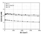
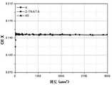
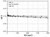
상기 제조예 1 내지 3에서 제조된 각각의 유기 전계발광 소자에 대해서, 전압-휘도, 전류밀도-휘도, 전압-전류밀도, 발광효율-휘도 및 전력효율-휘도를 각각 측정한 곡선을 도 2 내지 도 6에, X 및 Y 색좌표-휘도 곡선을 각각 도 7 및 도 8에, 전기발광 스펙트럼을 도 9에, 시간-휘도 곡선을 도 10에 나타내었으며, 이들 결과는 하기 표 1에 정리하였다.For each organic electroluminescent device manufactured in Preparation Examples 1 to 3, curves of voltage-luminance, current density-luminance, voltage-current density, luminous efficiency-luminance, and power efficiency-luminance, respectively, were measured. In FIG. 6, X and Y color coordinate-luminance curves are shown in FIGS. 7 and 8, electroluminescence spectra are shown in FIG. 9, and time-luminance curves are shown in FIG. 10. These results are summarized in Table 1 below.

※ 상기 표 1에서의 결과는 1000 니트(nit)에서의 측정값임.※ The results in Table 1 above are measured at 1000 nits.
상기 도 2 내지 10 및 표 1의 결과로부터 알 수 있는 바와 같이, 본 발명의 화합물인 화합물 4 및 40을 정공주입층 및 정공수송층 물질로서 사용한 본 발명의 유기 전계발광 소자는 2-TNATA를 사용한 비교예의 유기 전계발광 소자에 비해 구동전압이 낮음과 동시에 발광효율 및 수명이 높게 측정되었다. 따라서, 본 발명의 화합물이 유기 전계발광 소자의 정공주입층 물질 및 정공수송층 물질로 사용된 유기 전계발광 소자는 구동전압, 발광효율 및 수명 측면에서 현저히 개선되었다.As can be seen from the results of FIGS. 2 to 10 and Table 1, the organic electroluminescent device of the present invention using the
도 1은 일반적인 유기 전계발광 소자의 구조를 나타내는 단면도이다.1 is a cross-sectional view showing the structure of a general organic electroluminescent device.
도 2는 본 발명의 화합물 4 및 40과 2-TNATA를 정공주입층 및 정공수송층 물질로서 사용한 유기 전계발광 소자의 전압-휘도의 곡선이다.2 is a curve of voltage-luminance of an organic electroluminescent device using the
도 3은 본 발명의 화합물 4 및 40과 2-TNATA를 정공주입층 및 정공수송층 물질로서 사용한 유기 전계발광 소자의 전류밀도-휘도의 곡선이다.3 is a curve of current density-luminance of an organic electroluminescent device using the
도 4는 본 발명의 화합물 4 및 40과 2-TNATA를 정공주입층 및 정공수송층 물질로서 사용한 유기 전계발광 소자의 전압-전류밀도의 곡선이다.4 is a curve of voltage-current density of an organic electroluminescent
도 5는 본 발명의 화합물 4 및 40과 2-TNATA를 정공주입층 및 정공수송층 물질로서 사용한 유기 전계발광 소자의 발광효율-휘도의 곡선이다.5 is a curve of luminous efficiency-luminance of the organic electroluminescent device using the
도 6은 본 발명의 화합물 4 및 40과 2-TNATA를 정공주입층 및 정공수송층 물질로서 사용한 유기 전계발광 소자의 전력효율-휘도의 곡선이다.6 is a curve of power efficiency-luminance of the organic electroluminescent device using the
도 7 및 8은 각각 본 발명의 화합물 4 및 40과 2-TNATA를 정공주입층 및 정공수송층 물질로서 사용한 유기 전계발광 소자의 X 및 Y 색좌표-휘도 곡선이다.7 and 8 are X and Y color coordinate-luminance curves of the organic electroluminescent device using the
도 9는 본 발명의 화합물 4 및 40과 2-TNATA를 정공주입층 및 정공수송층 물질로서 사용한 유기 전계발광 소자의 전기발광 스펙트럼이다.9 is an electroluminescence spectrum of an organic electroluminescent device using the
도 10는 본 발명의 화합물 4 및 40과 2-TNATA를 정공주입층 및 정공수송층 물질로서 사용한 유기 전계발광 소자의 시간-휘도의 곡선이다.10 is a curve of time-luminance of the organic electroluminescent device using the
Claims (16)
Translated fromKorean


Priority Applications (1)
| Application Number | Priority Date | Filing Date | Title |
|---|---|---|---|
| KR1020080063612AKR101026171B1 (en) | 2008-07-01 | 2008-07-01 | Novel condensed carbazole derivatives and organic electroluminescent devices comprising the same |
Applications Claiming Priority (1)
| Application Number | Priority Date | Filing Date | Title |
|---|---|---|---|
| KR1020080063612AKR101026171B1 (en) | 2008-07-01 | 2008-07-01 | Novel condensed carbazole derivatives and organic electroluminescent devices comprising the same |
Publications (2)
| Publication Number | Publication Date |
|---|---|
| KR20100003624Atrue KR20100003624A (en) | 2010-01-11 |
| KR101026171B1 KR101026171B1 (en) | 2011-04-05 |
Family
ID=41813386
Family Applications (1)
| Application Number | Title | Priority Date | Filing Date |
|---|---|---|---|
| KR1020080063612AActiveKR101026171B1 (en) | 2008-07-01 | 2008-07-01 | Novel condensed carbazole derivatives and organic electroluminescent devices comprising the same |
Country Status (1)
| Country | Link |
|---|---|
| KR (1) | KR101026171B1 (en) |
Cited By (25)
| Publication number | Priority date | Publication date | Assignee | Title |
|---|---|---|---|---|
| WO2010151083A3 (en)* | 2009-06-25 | 2011-04-14 | 제일모직 주식회사 | Compound for an organic photoelectric element, and an organic photoelectric element comprising the same |
| US8597801B2 (en) | 2011-05-09 | 2013-12-03 | Samsung Display Co., Ltd. | Heterocyclic compound, organic light-emitting device including the heterocyclic compound, and flat display device including the organic light-emitting device |
| KR20140075674A (en)* | 2011-09-16 | 2014-06-19 | 도레이 카부시키가이샤 | Light-emitting element material and light-emitting element |
| WO2014104514A1 (en)* | 2012-12-31 | 2014-07-03 | 제일모직 주식회사 | Organic optoelectronic device, and display device including same |
| JP2014527522A (en)* | 2011-07-29 | 2014-10-16 | メルク パテント ゲーエムベーハー | Compounds for electronic devices |
| KR20150016845A (en)* | 2013-08-05 | 2015-02-13 | 제일모직주식회사 | Organic compound and organic optoelectric device and display device |
| US8974921B2 (en) | 2011-06-16 | 2015-03-10 | Samsung Display Co., Ltd. | Condensed-cyclic compound and organic light-emitting diode comprising the same |
| US8993128B2 (en) | 2011-06-16 | 2015-03-31 | Samsung Display Co., Ltd. | Heterocyclic compound and organic light-emitting device containing same |
| US8999528B2 (en) | 2012-08-03 | 2015-04-07 | Samsung Display Co., Ltd. | Condensation compound and organic light emitting device including the same |
| US9054321B2 (en) | 2011-10-18 | 2015-06-09 | Samsung Display Co., Ltd. | Heterocyclic compound and organic light-emitting device containing the same |
| KR101536185B1 (en)* | 2010-12-10 | 2015-07-14 | 주식회사 엠비케이 | Organic light compound and organic light device using the same |
| US9079903B2 (en) | 2011-11-03 | 2015-07-14 | Samsung Display Co., Ltd. | Heterocyclic compound and organic light-emitting device including the same |
| US9118021B2 (en) | 2012-07-26 | 2015-08-25 | Samsung Display Co., Ltd. | Heterocyclic compound and organic light-emitting device including the same |
| US9224961B2 (en) | 2010-10-25 | 2015-12-29 | Samsung Display Co., Ltd. | Condensed-cyclic compound, organic light-emitting diode comprising the same and flat panel display device comprising the organic light-emitting diode |
| KR20160008570A (en)* | 2013-05-16 | 2016-01-22 | 가부시키가이샤 한도오따이 에네루기 켄큐쇼 | Light-emitting element, light-emitting device, electronic device, and lighting device |
| US9255084B2 (en) | 2011-08-22 | 2016-02-09 | Samsung Display Co., Ltd. | Heterocyclic compound and organic light-emitting device containing the same |
| US9278927B2 (en) | 2011-08-03 | 2016-03-08 | Samsung Display Co., Ltd. | Heterocyclic compound and organic light-emitting device including the same |
| US9385327B2 (en) | 2012-08-01 | 2016-07-05 | Samsung Display Co., Ltd. | Heterocyclic compound and organic light-emitting device including the same |
| US9403795B2 (en) | 2011-08-05 | 2016-08-02 | Samsung Display Co., Ltd. | Carbazole-based compound and organic light-emitting diode comprising the same |
| US9416107B2 (en) | 2011-06-29 | 2016-08-16 | Samsung Display Co., Ltd. | Heterocyclic compound and organic light-emitting device including the same |
| US9893301B2 (en) | 2012-07-25 | 2018-02-13 | Samsung Display Co., Ltd. | Heterocyclic compounds and organic light-emitting devices including the same |
| US10249824B2 (en) | 2012-05-03 | 2019-04-02 | Samsung Display Co., Ltd. | Condensed-cyclic compound and organic light-emitting diode comprising the same |
| US10749118B2 (en) | 2014-06-26 | 2020-08-18 | Samsung Display Co., Ltd. | Heterocyclic compound and organic light-emitting device including the same |
| CN113979919A (en)* | 2021-11-24 | 2022-01-28 | 阜阳欣奕华材料科技有限公司 | Indolo spirofluorene organic compound, organic electroluminescent device and display device |
| CN113979920A (en)* | 2021-11-24 | 2022-01-28 | 阜阳欣奕华材料科技有限公司 | Indolo spirofluorene organic compound, organic electroluminescent device and display device |
Families Citing this family (1)
| Publication number | Priority date | Publication date | Assignee | Title |
|---|---|---|---|---|
| KR102095837B1 (en) | 2018-06-28 | 2020-04-01 | 영남대학교 산학협력단 | Novel Method for Preparing Carbazole Derivatives, Novel Carbazole Derivatives Made thereby, Composition Comprising the Same, and Material for Organic Light Emitting Diode Comprising the Same |
Family Cites Families (3)
| Publication number | Priority date | Publication date | Assignee | Title |
|---|---|---|---|---|
| KR100669718B1 (en) | 2004-07-29 | 2007-01-16 | 삼성에스디아이 주식회사 | Organic electroluminescent element |
| KR100670185B1 (en) | 2004-12-30 | 2007-02-28 | 한국화인케미칼주식회사 | 1,5-Diaminonaphthalene and its derivatives |
| WO2008010377A1 (en) | 2006-07-21 | 2008-01-24 | Toyo Ink Manufacturing Co., Ltd. | Carbazole-containing amine compound and use thereof |
- 2008
- 2008-07-01KRKR1020080063612Apatent/KR101026171B1/enactiveActive
Cited By (33)
| Publication number | Priority date | Publication date | Assignee | Title |
|---|---|---|---|---|
| WO2010151083A3 (en)* | 2009-06-25 | 2011-04-14 | 제일모직 주식회사 | Compound for an organic photoelectric element, and an organic photoelectric element comprising the same |
| US9017827B2 (en) | 2009-06-25 | 2015-04-28 | Cheil Industries, Inc. | Indenocarbazole compound for optoelectronic device, organic light emitting diode including the same and display including the organic light emitting diode |
| US9224961B2 (en) | 2010-10-25 | 2015-12-29 | Samsung Display Co., Ltd. | Condensed-cyclic compound, organic light-emitting diode comprising the same and flat panel display device comprising the organic light-emitting diode |
| KR101536185B1 (en)* | 2010-12-10 | 2015-07-14 | 주식회사 엠비케이 | Organic light compound and organic light device using the same |
| US8597801B2 (en) | 2011-05-09 | 2013-12-03 | Samsung Display Co., Ltd. | Heterocyclic compound, organic light-emitting device including the heterocyclic compound, and flat display device including the organic light-emitting device |
| US8993128B2 (en) | 2011-06-16 | 2015-03-31 | Samsung Display Co., Ltd. | Heterocyclic compound and organic light-emitting device containing same |
| US8974921B2 (en) | 2011-06-16 | 2015-03-10 | Samsung Display Co., Ltd. | Condensed-cyclic compound and organic light-emitting diode comprising the same |
| US9416107B2 (en) | 2011-06-29 | 2016-08-16 | Samsung Display Co., Ltd. | Heterocyclic compound and organic light-emitting device including the same |
| JP2014527522A (en)* | 2011-07-29 | 2014-10-16 | メルク パテント ゲーエムベーハー | Compounds for electronic devices |
| US9780311B2 (en) | 2011-07-29 | 2017-10-03 | Merck Patent Gmbh | Compounds for electronic devices |
| US9278927B2 (en) | 2011-08-03 | 2016-03-08 | Samsung Display Co., Ltd. | Heterocyclic compound and organic light-emitting device including the same |
| US9403795B2 (en) | 2011-08-05 | 2016-08-02 | Samsung Display Co., Ltd. | Carbazole-based compound and organic light-emitting diode comprising the same |
| US9255084B2 (en) | 2011-08-22 | 2016-02-09 | Samsung Display Co., Ltd. | Heterocyclic compound and organic light-emitting device containing the same |
| KR20140075674A (en)* | 2011-09-16 | 2014-06-19 | 도레이 카부시키가이샤 | Light-emitting element material and light-emitting element |
| US9054321B2 (en) | 2011-10-18 | 2015-06-09 | Samsung Display Co., Ltd. | Heterocyclic compound and organic light-emitting device containing the same |
| US9079903B2 (en) | 2011-11-03 | 2015-07-14 | Samsung Display Co., Ltd. | Heterocyclic compound and organic light-emitting device including the same |
| US10249824B2 (en) | 2012-05-03 | 2019-04-02 | Samsung Display Co., Ltd. | Condensed-cyclic compound and organic light-emitting diode comprising the same |
| US9893301B2 (en) | 2012-07-25 | 2018-02-13 | Samsung Display Co., Ltd. | Heterocyclic compounds and organic light-emitting devices including the same |
| US9118021B2 (en) | 2012-07-26 | 2015-08-25 | Samsung Display Co., Ltd. | Heterocyclic compound and organic light-emitting device including the same |
| US9385327B2 (en) | 2012-08-01 | 2016-07-05 | Samsung Display Co., Ltd. | Heterocyclic compound and organic light-emitting device including the same |
| US8999528B2 (en) | 2012-08-03 | 2015-04-07 | Samsung Display Co., Ltd. | Condensation compound and organic light emitting device including the same |
| WO2014104514A1 (en)* | 2012-12-31 | 2014-07-03 | 제일모직 주식회사 | Organic optoelectronic device, and display device including same |
| KR20140087883A (en)* | 2012-12-31 | 2014-07-09 | 제일모직주식회사 | Organic optoelectronic device and display including the same |
| CN104903421A (en)* | 2012-12-31 | 2015-09-09 | 第一毛织株式会社 | Organic optoelectronic device, and display device including same |
| US11462701B2 (en) | 2013-05-16 | 2022-10-04 | Semiconductor Energy Laboratory Co., Ltd. | Light-emitting element, light-emitting device, electronic device, and lighting device |
| KR20240108508A (en)* | 2013-05-16 | 2024-07-09 | 가부시키가이샤 한도오따이 에네루기 켄큐쇼 | Light-emitting element, light-emitting device, electronic device, and lighting device |
| KR20160008570A (en)* | 2013-05-16 | 2016-01-22 | 가부시키가이샤 한도오따이 에네루기 켄큐쇼 | Light-emitting element, light-emitting device, electronic device, and lighting device |
| KR20230156154A (en)* | 2013-05-16 | 2023-11-13 | 가부시키가이샤 한도오따이 에네루기 켄큐쇼 | Light-emitting element, light-emitting device, electronic device, and lighting device |
| US9755157B2 (en) | 2013-08-05 | 2017-09-05 | Cheil Industries, Inc. | Organic compound and organic optoelectric device and display device |
| KR20150016845A (en)* | 2013-08-05 | 2015-02-13 | 제일모직주식회사 | Organic compound and organic optoelectric device and display device |
| US10749118B2 (en) | 2014-06-26 | 2020-08-18 | Samsung Display Co., Ltd. | Heterocyclic compound and organic light-emitting device including the same |
| CN113979920A (en)* | 2021-11-24 | 2022-01-28 | 阜阳欣奕华材料科技有限公司 | Indolo spirofluorene organic compound, organic electroluminescent device and display device |
| CN113979919A (en)* | 2021-11-24 | 2022-01-28 | 阜阳欣奕华材料科技有限公司 | Indolo spirofluorene organic compound, organic electroluminescent device and display device |
Also Published As
| Publication number | Publication date |
|---|---|
| KR101026171B1 (en) | 2011-04-05 |
Similar Documents
| Publication | Publication Date | Title |
|---|---|---|
| KR101026171B1 (en) | Novel condensed carbazole derivatives and organic electroluminescent devices comprising the same | |
| KR101017945B1 (en) | Asymmetric anthracene derivative and organic electroluminescent device comprising the same | |
| KR101026173B1 (en) | Novel carbazole derivatives and organic electroluminescent devices comprising the same | |
| KR101738607B1 (en) | Organic electroluminescent device | |
| KR102160946B1 (en) | Organic electroluminescent compound comprising acridine derivative and organic electroluminescent device comprising same | |
| KR20090028943A (en) | Hole injection layer / hole transport layer material and organic light emitting device comprising the same | |
| KR101529164B1 (en) | New organic electroluminescent compounds and organic electroluminescent device comprising the same | |
| JP4878819B2 (en) | Novel triazine derivative and organic electroluminescence device containing the same | |
| KR101026175B1 (en) | Fluorene carbazole derivatives and organic light emitting device comprising the same | |
| KR102169273B1 (en) | Organic electroluminescent compound comprising acridine derivative and organic electroluminescent device comprising same | |
| KR20100003632A (en) | Novel biphenyl derivatives and electroluminescent device comprising same | |
| KR20090114716A (en) | Hole transport layer material and organic electroluminescent device comprising the same | |
| KR20100007639A (en) | Novel phenyl-fluorene derivatives and organic electroluminescent device comprising the same | |
| KR102402220B1 (en) | Novel blue fluorescent host compound and organic electroluminescent device comprising same | |
| KR100994765B1 (en) | Organic electroluminescent device comprising fluorene-based light emitting material | |
| KR101551466B1 (en) | New organic electroluminescent compounds and organic electroluminescent device comprising the same | |
| KR20140033301A (en) | Novel organic electroluminescent compound substituted with deuterium and organic electroluminescent device comprising same | |
| KR102394380B1 (en) | Novel electroluminescent compound and organic electroluminescent device comprising same | |
| KR102437956B1 (en) | Novel compound and organic light emitting device comprising same | |
| KR20090016048A (en) | Green / Blue Fluorescent Light Emitting Material and Organic Electroluminescent Device Comprising the Same | |
| KR100951441B1 (en) | Hole injection layer / hole transport layer material and organic light emitting device comprising the same | |
| KR20090036392A (en) | Hole injection layer / hole transport layer material and organic light emitting device comprising the same | |
| KR102390954B1 (en) | Novel compound and organic electroluminescent device comprising same | |
| KR100877344B1 (en) | Green / Blue Fluorescent Light Emitting Material and Organic Electroluminescent Device Comprising the Same | |
| KR100976807B1 (en) | Anthracene Derivatives and Organic Electroluminescent Devices Comprising the Same |
Legal Events
| Date | Code | Title | Description |
|---|---|---|---|
| A201 | Request for examination | ||
| PA0109 | Patent application | Patent event code:PA01091R01D Comment text:Patent Application Patent event date:20080701 | |
| PA0201 | Request for examination | ||
| N231 | Notification of change of applicant | ||
| PN2301 | Change of applicant | Patent event date:20090909 Comment text:Notification of Change of Applicant Patent event code:PN23011R01D | |
| PG1501 | Laying open of application | ||
| E902 | Notification of reason for refusal | ||
| PE0902 | Notice of grounds for rejection | Comment text:Notification of reason for refusal Patent event date:20100726 Patent event code:PE09021S01D | |
| E701 | Decision to grant or registration of patent right | ||
| PE0701 | Decision of registration | Patent event code:PE07011S01D Comment text:Decision to Grant Registration Patent event date:20110222 | |
| GRNT | Written decision to grant | ||
| PR0701 | Registration of establishment | Comment text:Registration of Establishment Patent event date:20110324 Patent event code:PR07011E01D | |
| PR1002 | Payment of registration fee | Payment date:20110325 End annual number:3 Start annual number:1 | |
| PG1601 | Publication of registration | ||
| FPAY | Annual fee payment | Payment date:20140218 Year of fee payment:4 | |
| PR1001 | Payment of annual fee | Payment date:20140218 Start annual number:4 End annual number:4 | |
| FPAY | Annual fee payment | Payment date:20150302 Year of fee payment:5 | |
| PR1001 | Payment of annual fee | Payment date:20150302 Start annual number:5 End annual number:5 | |
| FPAY | Annual fee payment | Payment date:20161221 Year of fee payment:7 | |
| PR1001 | Payment of annual fee | Payment date:20161221 Start annual number:7 End annual number:7 | |
| FPAY | Annual fee payment | Payment date:20171207 Year of fee payment:8 | |
| PR1001 | Payment of annual fee | Payment date:20171207 Start annual number:8 End annual number:8 | |
| FPAY | Annual fee payment | Payment date:20181031 Year of fee payment:9 | |
| PR1001 | Payment of annual fee | Payment date:20181031 Start annual number:9 End annual number:9 | |
| FPAY | Annual fee payment | Payment date:20191029 Year of fee payment:10 | |
| PR1001 | Payment of annual fee | Payment date:20191029 Start annual number:10 End annual number:10 | |
| PR1001 | Payment of annual fee | Payment date:20201207 Start annual number:11 End annual number:11 | |
| PR1001 | Payment of annual fee | Payment date:20211117 Start annual number:12 End annual number:12 | |
| PR1001 | Payment of annual fee | Payment date:20221202 Start annual number:13 End annual number:13 | |
| PR1001 | Payment of annual fee | Payment date:20231109 Start annual number:14 End annual number:14 |