KR20100002727A - A wind power apparatus - Google Patents
A wind power apparatusDownload PDFInfo
- Publication number
- KR20100002727A KR20100002727AKR1020080062730AKR20080062730AKR20100002727AKR 20100002727 AKR20100002727 AKR 20100002727AKR 1020080062730 AKR1020080062730 AKR 1020080062730AKR 20080062730 AKR20080062730 AKR 20080062730AKR 20100002727 AKR20100002727 AKR 20100002727A
- Authority
- KR
- South Korea
- Prior art keywords
- generator
- connector
- speed increaser
- speed
- rotor hub
- Prior art date
- Legal status (The legal status is an assumption and is not a legal conclusion. Google has not performed a legal analysis and makes no representation as to the accuracy of the status listed.)
- Granted
Links
Images


Classifications
- F—MECHANICAL ENGINEERING; LIGHTING; HEATING; WEAPONS; BLASTING
- F03—MACHINES OR ENGINES FOR LIQUIDS; WIND, SPRING, OR WEIGHT MOTORS; PRODUCING MECHANICAL POWER OR A REACTIVE PROPULSIVE THRUST, NOT OTHERWISE PROVIDED FOR
- F03D—WIND MOTORS
- F03D1/00—Wind motors with rotation axis substantially parallel to the air flow entering the rotor
- F03D1/06—Rotors
- F03D1/065—Rotors characterised by their construction elements
- F03D1/0658—Arrangements for fixing wind-engaging parts to a hub
- F—MECHANICAL ENGINEERING; LIGHTING; HEATING; WEAPONS; BLASTING
- F03—MACHINES OR ENGINES FOR LIQUIDS; WIND, SPRING, OR WEIGHT MOTORS; PRODUCING MECHANICAL POWER OR A REACTIVE PROPULSIVE THRUST, NOT OTHERWISE PROVIDED FOR
- F03D—WIND MOTORS
- F03D13/00—Assembly, mounting or commissioning of wind motors; Arrangements specially adapted for transporting wind motor components
- F03D13/10—Assembly of wind motors; Arrangements for erecting wind motors
- F—MECHANICAL ENGINEERING; LIGHTING; HEATING; WEAPONS; BLASTING
- F03—MACHINES OR ENGINES FOR LIQUIDS; WIND, SPRING, OR WEIGHT MOTORS; PRODUCING MECHANICAL POWER OR A REACTIVE PROPULSIVE THRUST, NOT OTHERWISE PROVIDED FOR
- F03D—WIND MOTORS
- F03D7/00—Controlling wind motors
- F03D7/02—Controlling wind motors the wind motors having rotation axis substantially parallel to the air flow entering the rotor
- F—MECHANICAL ENGINEERING; LIGHTING; HEATING; WEAPONS; BLASTING
- F03—MACHINES OR ENGINES FOR LIQUIDS; WIND, SPRING, OR WEIGHT MOTORS; PRODUCING MECHANICAL POWER OR A REACTIVE PROPULSIVE THRUST, NOT OTHERWISE PROVIDED FOR
- F03D—WIND MOTORS
- F03D80/00—Details, components or accessories not provided for in groups F03D1/00 - F03D17/00
- F03D80/50—Maintenance or repair
- F—MECHANICAL ENGINEERING; LIGHTING; HEATING; WEAPONS; BLASTING
- F03—MACHINES OR ENGINES FOR LIQUIDS; WIND, SPRING, OR WEIGHT MOTORS; PRODUCING MECHANICAL POWER OR A REACTIVE PROPULSIVE THRUST, NOT OTHERWISE PROVIDED FOR
- F03D—WIND MOTORS
- F03D9/00—Adaptations of wind motors for special use; Combinations of wind motors with apparatus driven thereby; Wind motors specially adapted for installation in particular locations
- F03D9/20—Wind motors characterised by the driven apparatus
- F03D9/25—Wind motors characterised by the driven apparatus the apparatus being an electrical generator
- F—MECHANICAL ENGINEERING; LIGHTING; HEATING; WEAPONS; BLASTING
- F05—INDEXING SCHEMES RELATING TO ENGINES OR PUMPS IN VARIOUS SUBCLASSES OF CLASSES F01-F04
- F05B—INDEXING SCHEME RELATING TO WIND, SPRING, WEIGHT, INERTIA OR LIKE MOTORS, TO MACHINES OR ENGINES FOR LIQUIDS COVERED BY SUBCLASSES F03B, F03D AND F03G
- F05B2240/00—Components
- F05B2240/20—Rotors
- F05B2240/21—Rotors for wind turbines
- F05B2240/221—Rotors for wind turbines with horizontal axis
- Y—GENERAL TAGGING OF NEW TECHNOLOGICAL DEVELOPMENTS; GENERAL TAGGING OF CROSS-SECTIONAL TECHNOLOGIES SPANNING OVER SEVERAL SECTIONS OF THE IPC; TECHNICAL SUBJECTS COVERED BY FORMER USPC CROSS-REFERENCE ART COLLECTIONS [XRACs] AND DIGESTS
- Y02—TECHNOLOGIES OR APPLICATIONS FOR MITIGATION OR ADAPTATION AGAINST CLIMATE CHANGE
- Y02E—REDUCTION OF GREENHOUSE GAS [GHG] EMISSIONS, RELATED TO ENERGY GENERATION, TRANSMISSION OR DISTRIBUTION
- Y02E10/00—Energy generation through renewable energy sources
- Y02E10/70—Wind energy
- Y02E10/72—Wind turbines with rotation axis in wind direction
- Y—GENERAL TAGGING OF NEW TECHNOLOGICAL DEVELOPMENTS; GENERAL TAGGING OF CROSS-SECTIONAL TECHNOLOGIES SPANNING OVER SEVERAL SECTIONS OF THE IPC; TECHNICAL SUBJECTS COVERED BY FORMER USPC CROSS-REFERENCE ART COLLECTIONS [XRACs] AND DIGESTS
- Y02—TECHNOLOGIES OR APPLICATIONS FOR MITIGATION OR ADAPTATION AGAINST CLIMATE CHANGE
- Y02E—REDUCTION OF GREENHOUSE GAS [GHG] EMISSIONS, RELATED TO ENERGY GENERATION, TRANSMISSION OR DISTRIBUTION
- Y02E10/00—Energy generation through renewable energy sources
- Y02E10/70—Wind energy
- Y02E10/728—Onshore wind turbines
Landscapes
- Engineering & Computer Science (AREA)
- Life Sciences & Earth Sciences (AREA)
- Sustainable Development (AREA)
- Sustainable Energy (AREA)
- Chemical & Material Sciences (AREA)
- Combustion & Propulsion (AREA)
- Mechanical Engineering (AREA)
- General Engineering & Computer Science (AREA)
- Power Engineering (AREA)
- Wind Motors (AREA)
Abstract
Translated fromKoreanDescription
Translated fromKorean본 발명은 풍력 발전 장치에 관한 것으로서, 특히 허브와 증속기 사이에 컨넥트를 적용함으로써 증속기의 분해 과정을 단순화하여 증속기의 유지/보수를 용이하게 하고 그 비용을 절감하며, 경량화된 증속기를 제공하는 풍력 발전 장치에 관한 것이다.The present invention relates to a wind turbine, and in particular, by applying a connection between the hub and the gearbox to simplify the disassembly process of the gearbox, thereby facilitating maintenance and repair of the gearbox and providing a lighter gearbox. It relates to a wind power generator.
일반적으로 풍력 발전 장치는 자연의 바람으로 풍차를 돌리고 이 풍차의 회전력을 이용하여 발전기의 축을 돌려 발전하는 것이다.In general, a wind power generator is to rotate a windmill by natural wind and generate power by rotating the shaft of a generator using the rotational force of the windmill.
보통 수평축 풍력 발전 장치에서 증속기를 사용하여 발전기로 회전 토크를 전달하는 동력 전달계는 크게 2가지로 나눌 수 있다.In general, a power transmission system that transmits rotational torque to a generator using a gearbox in a horizontal wind turbine can be divided into two types.
도 1과 도 2는 종래의 풍력발전시스템의 구성도를 나타낸 것이다.1 and 2 show the configuration of a conventional wind power generation system.
가장 일반적인 방법은 도 1과 같은 주축(14)을 갖는 시스템으로, 주축(14)을 통하여 로터시스템(11)에서의 동력이 나셀 프레임(17)에 부착된 증속기(15)로 전달된다. 상기 주축(14)은 2개의 베어링(13)에 의하여 지지되고 있으며 이 베어링(13) 은 나셀 프레임(17)에 고정되어 로터 시스템(11)으로부터 전달되는 하중을 지지하고, 회전토크를 증속기(15)로 전달해 주는 역할을 한다. 주축(14)을 통해 전달된 동력은 증속기(15)를 거치면서 회전 속도와 회전 토크가 최초 상태로부터 변경되어 증속기(15) 후단의 발전기(16)로 전달된다.The most common method is a system with a
상기 기술된 동력 전달계를 가진 종래의 풍력 발전 장치의 경우, 증속기(15) 및 발전기(16)가 주축(14)과 별도로 분리되어 분해/조립될 수 있다. 하지만 로터 시스템(11)으로부터 전달되는 회전 토크 외에도 추력(바람방향 성분 힘), 모멘트 등이 전달되어 증속기(15) 파손의 원인으로 보고되고 있다. 이러한 문제를 해결하고자 상기 기술된 하중들에 대한 강성을 지녀야 하고, 이로 인해 증속기(15)가 점차 대형화되고 무거워 지는 문제점이 있다.In the case of the conventional wind turbine generator having the power transmission system described above, the speed increaser 15 and the
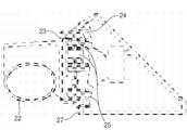
다른 방법으로 도 2의 경우와 같이 주축이 없는 로터 시스템의 허브(22) 후단과 증속기(25) 전단을 직접 연결하는 일체형 시스템이다. 본 시스템은 메인 베어링(23)을 포함하는 일체형 증속기(25)를 제작하고 상기 일체형 증속기(25)를 나셀 프레임(27)에 고정하는 방식이다. 이 경우 로터 시스템의 허브(22)와 증속기(25) 사이에서 1개의 베어링(23)을 사용하는 경우가 일반적이며, 하중 조건에 따라서 복열 테이퍼 롤러 베어링이나 3열 롤러 베어링 등이 사용된다.Alternatively, as in the case of FIG. 2, the integrated system directly connects the rear end of the
상기 기술된 동력 전달계를 가진 종래의 풍력 발전 장치의 경우, 전자와는 달리 증속기(25)가 소형화/경량화될 수 있는 장점을 갖지만, 허브(22)와 증속기(25) 입력단 간의 연결부위가 복잡해지게 되고, 허브(22) 및 나셀 프레임(27)과의 체결 조건 등으로 인해 증속기(25) 자체의 분해/조립이 불가능해 지게 되는 단 점이 있다. 이러한 이유로 인해 증속기(25)의 유지/보수를 위한 분해/조립 시 풍력발전시스템 설치에 필요한 대형 크레인을 동원하여 로터 시스템 및 나셀 프레임(27) 전체를 풍력 발전 장치가 설치된 타워로부터 분리하여야 한다는 번거로움이 따른다는 문제점이 있다.In the case of the conventional wind power generator having the above-described power transmission system, unlike the former, the
본 발명은 상기와 같은 점을 감안하여 안출된 것으로서, 허브와 증속기 사이에 컨넥트를 적용함으로써 증속기의 분해 과정을 단순화하여 증속기의 유지/보수를 용이하게 하고 증속기를 별도로 분해/조립할 수 있으며 전체구조가 단순화되어 소형화/경량화된 동력전달계가 구비된 풍력 발전 장치를 제공하는 것이다.The present invention has been made in view of the above, by applying a connection between the hub and the gearbox to simplify the disassembly process of the gearbox to facilitate the maintenance and repair of the gearbox and to disassemble / assemble the gearbox separately. The overall structure is simplified to provide a wind turbine generator with a miniaturized / lightened power train.
상기 목적을 달성하기 위한 본 발명에 따른 풍력 발전 장치는 전면의 외부 면에 메인 베어링이 설치되는 나셀 프레임; 상기 나셀 프레임의 전방에 구비되어 회전하는 로터허브; 상기 메인 베어링의 내 측면에 끼워 맞춤으로 부착되어 상기 로터허브로부터 발생하는 회전 토크를 전달하는 컨넥트; 상기 컨넥트의 후방에 연결되어 상기 컨넥트로부터 전달된 회전 속도를 증대시키는 증속기; 상기 증속기의 후방에 연결되어 회전토크를 전달받는 발전기;를 포함하는 것을 특징으로 한다.Wind turbine generator according to the present invention for achieving the above object is a nacelle frame is installed in the main bearing on the outer surface of the front; A rotor hub provided and rotated in front of the nacelle frame; A connector that is fitted to the inner side of the main bearing to transmit rotational torque generated from the rotor hub; An increaser connected to the rear of the connector to increase the rotational speed transmitted from the connector; It is characterized in that it comprises a; generator connected to the rear of the speed increaser receives a rotation torque.
상기 컨넥트는 상기 나셀 프레임 내측에서 메인 베어링에 끼워 맞춤으로 부착되고 상기 증속기 커버와 연결된 제1컨넥트; 상기 나셀프레임 외측에서 메인 베어링에 끼워 맞춤으로 부착되고 상기 로터허브에 연결된 제2컨넥트;를 포함하는 것이 바람직하다.The connector may include a first connector fitted to the main bearing inside the nacelle frame and connected to the accelerator cover; And a second connector fitted to the main bearing outside the nacelle frame and connected to the rotor hub.
상기 증속기 측면에 부착되어 상기 증속기 자체의 회전을 방지하도록 하는 반토크 장치를 더 포함하는 것이 좋다.It is preferable to further include an anti-torque device attached to the side of the speed reducer to prevent rotation of the speed increaser itself.
상기 반토크 장치는 합성수지 재질이거나 링크 구조, 또는 유압식으로 작동되는 것이 바람직하다.The anti-torque device is preferably made of synthetic resin, link structure, or hydraulically operated.
또한 상기 컨넥트 내측에 형성된 삽입홈에 구비되어 상기 로터허브의 회전을 방지할 수 있는 회전방지부재를 더 포함하는 것이 좋다.In addition, it is preferable to further include an anti-rotation member provided in the insertion groove formed inside the connector to prevent the rotation of the rotor hub.
상기 증속기의 일면에는 상기 로터허브의 비상제동을 위한 브레이크부가 더 구비되는 것이 바람직하다.It is preferable that one side of the speed increaser is further provided with a brake for emergency braking of the rotor hub.
상기 증속기는 차동기어를 이용하여 회전속도를 변환하도록 하는 것이 좋다.The speed increaser may be configured to convert a rotation speed by using a differential gear.
상기 발전기는 영구자석형 동기 발전기 또는 이중 여자 유도 발전기인 것이 바람직하다.The generator is preferably a permanent magnet synchronous generator or a double excitation induction generator.
상기 증속기의 출력축과 상기 발전기의 입력축 사이에 커플링이 더 구비된 것이 좋다.Coupling is further provided between the output shaft of the speed increaser and the input shaft of the generator.
상기 발전기의 하부에 구비되어 상기 발전기의 회전운동에 따른 진동을 흡수하는 방진 받침부를 더 포함하는 것이 바람직하다.It is preferable to further include a dustproof support provided on the lower portion of the generator to absorb the vibration according to the rotational movement of the generator.
상기 나셀 프레임과 상기 지지 구조물 사이에 구비되어 발전기의 회전 운동에 따른 진동을 흡수하는 방진 장치를 더 포함하는 것이 바람직하다.It is preferable to further include a dustproof device provided between the nacelle frame and the support structure to absorb vibration according to the rotational movement of the generator.
본 발명에 따른 풍력 발전 장치에 의하면 허브와 증속기 사이에 컨넥트를 적용함으로써 증속기의 분해 과정을 단순화하여 증속기의 유지/보수를 용이하게 하고 증속기를 별도로 분해/조립할 수 있으며 전체구조가 단순화되어 소형화/경량화된 동력전달계를 구비하여 원가가 절감되는 효과가 있다.According to the wind power generator according to the present invention, by applying a connection between the hub and the speed increaser, the disassembling process of the speed increaser can be simplified to facilitate maintenance and repair of the speed increaser, and the speed reducer can be separately disassembled / assembled and the overall structure is simplified. Cost reduction is achieved by having a miniaturized / lightened power train.
본 발명의 상기와 같은 목적, 특징 및 다른 장점들은 첨부도면을 참조하여 본 발명의 바람직한 실시 예를 상세히 설명함으로써 더욱 명백해질 것이다. 이하, 첨부된 도면을 참조하여 본 발명의 실시 예에 따른 풍력 발전 장치를 상세히 설명하기로 한다.The above objects, features and other advantages of the present invention will become more apparent by describing the preferred embodiments of the present invention in detail with reference to the accompanying drawings. Hereinafter, a wind turbine generator according to an embodiment of the present invention will be described in detail with reference to the accompanying drawings.
도 3은 본 발명의 일 실시 예에 따른 풍력 발전 장치의 구성도이고, 도 4는 도 3의 풍력 발전 장치의 상세 측 단면도이다.3 is a configuration diagram of a wind turbine generator according to an embodiment of the present invention, Figure 4 is a detailed side cross-sectional view of the wind turbine generator of FIG.
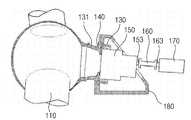
도 3과 도 4를 구체적으로 살펴보면, 본 발명에 따른 풍력 발전 장치는 전면의 외부 면에 메인 베어링(140)이 설치되는 나셀 프레임(180), 나셀 프레임(180)의 전방에 구비되어 회전하는 로터허브(110), 메인 베어링(140)의 내 측면에 끼워 맞춤으로 부착되어 로터허브(110)로부터 발생하는 회전 토크를 전달하는 컨넥트(130,131), 컨넥트(130,131)의 후방에 연결되어 컨넥트(130,131)로부터 전달된 회전 속도를 증대시키는 증속기(150), 증속기(150)의 후방에 연결되어 회전토크를 전달받는 발전기(170)를 포함한다.3 and 4, the wind turbine generator according to the present invention is provided in the front of the
나셀 프레임(180)은 타워의 상부에 회전 가능하게 설치되면서 전방에 메인 베어링(140)이 장착되는 것으로, 전방에 설치된 로터허브(110)를 회전 가능하게 지지하는 역할을 한다.The
로터허브(110)는 외측에 블레이드가 조립되는 것으로, 로터허브(110)에 조립 되는 블레이드가 바람에 의해 회전되면서 로터허브(110)가 회전됨과 동시에 증속기(150)에 회전력이 전달된다.The
본 발명에서 컨넥트(130,131)는 증속기(150)와 로터허브(110)를 연결하는 구성부품을 의미한다.In the present invention, the
컨넥트는 나셀 프레임(180) 내측에서 메인 베어링(140)에 끼워 맞춤으로 부착되고 증속기(150) 커버와 연결된 제1컨넥트(130)와 나셀 프레임(180) 외측에서 메인 베어링(140)에 끼워 맞춤으로 부착되고 로터허브(110)에 연결된 제2컨넥트(131)으로 구성된다. 제1컨넥트(130)와 제2컨넥트(131)는 로터허브(110)에서 발생한 회전토크를 증속기(150)에 전달하는 역할을 한다.The connector is fitted to the main bearing 140 inside the
컨넥트(130,131)는 메인 베어링(140)에 적합한 하중을 가해주는 역할을 하게 되는데 이때 적용된 하중을 예압이라 한다. 상기 예압은 풍력 발전 장치의 설계시에 도출되는 하중으로서 메인 베어링(140) 자체의 피로수명은 물론 장치 전체 구조물의 피로 수명을 증가시키는 중요한 역할을 하게 된다. 컨넥트(130,131)는 메인 베어링(140)의 내측면에 접촉되어 회전하는 형태로 억지 끼워맞춤을 통해 조립되며, 볼트의 조임 강도 조절을 통해 예압량을 조절하게 된다.The
증속기(150)는 입력된 회전 속도를 증대시킨 후에 외부로 전달하는 역할을 한다. 도 3과 도 4에 도시된 풍력 발전 장치는 컨넥트(130,131)의 회전에 따라 증속기(150)의 커버가 회전하고, 이에 의하여 증속기(150) 내부에서 회전 속도가 증가되며, 이를 증속기(150)의 일측에 형성된 출력축(153)으로 전달한다.The
증속기(150)는 3단에 걸쳐 회전 속도를 변환시킬 수 있는 차동기어를 사용할 수 있고, 1단과 2단에 4~8개의 유성치차를 적용하여 원할한 하중 분배를 꾀하고 구조적으로 안정성을 갖추어 컴펙트한 유성치차를 포함한 3단 증속기를 사용할 수 있다.Gearhead 150 can use a differential gear that can convert the rotational speed over three stages, by applying four to eight planetary gears in the first and second stages to achieve a smooth load distribution and structural stability A three-speed gearbox with a compact planetary gearbox can be used.
이 경우 증속기(150)의 커버만이 회전하고, 증속기(150) 자체는 회전하지 않아야 하므로 이를 위하여 증속기(150) 측면에는 반토크 장치(155)가 구비될 수 있다.In this case, only the cover of the speed increaser 150 rotates and the speed increaser 150 itself does not rotate. For this purpose, the
반토크 장치(155)는 증속기(150) 자체에 걸리는 토크를 줄이기 위한 장치로서, 증속기(150) 커버의 회전력을 흡수할 수 있는 재질 및 구조가 필요하다.The
이를 위하여 본 발명에서는 반토크 장치(155)에 합성수지 재질을 이용하여 충격을 흡수할 수 있으며, 링크 구조를 사용하여 증속기(150)의 변위가 변하더라도 반토크 장치(155)가 분리되지 않도록 할 수 있으며, 특히 유압식으로 작동시켜 반토크 장치(155)가 증속기(150)에 가능한 큰 외력에 의해 부착될 수 있도록 하였다.To this end, in the present invention, the
전체 시스템에서 반토크 장치(155)는 로터허브(110)로부터 전달된 회전 토크가 증속기(150)를 거쳐 효과적으로 발전기(170)로 전달되도록 하는 역할을 한다.In the entire system, the
본 발명에 따른 풍력 발전 장치에 있어서 추가적으로 적절한 하중 분배를 위하여 별도의 입력축(미도시)을 갖도록 설계 변경하여 적용할 수 있다.In the wind turbine generator according to the present invention may be additionally applied by changing the design to have a separate input shaft (not shown) for proper load distribution.
풍력 발전 장치의 작동 중 비상 시 로터허브(110)의 비상제동을 위하여 증속기(150)의 발전기(170) 방향 일면에는 브레이크부(165)가 더 구비될 수 있다. 브레이크부(165)는 급제동을 위한 장치로서 충격흡수를 위하여 합성수지 또는 마찰에 강한 재질로 형성되는 것이 바람직하다.The
발전기(170)는 전기를 생산하는 장치로서, 본 발명에서의 발전기(170)에는 증속기(150)에 구비된 출력축(153)과 연결되도록 입력축(163)이 구비되고, 입력축(163)은 출력축(153)의 회전과 동시에 회전하게 되어 입력축(163)이 설치된 발전기(170) 내부에서는 전기가 생산된다.
발전기(170)로는 영구 자석형 동기발전기 또는 이중여자 유도발전기를 사용할 수 있다.As the
증속기(150)의 출력축(153)과 발전기(170)의 입력축(163) 사이에는 회전력의 효과적인 전달을 위하여 커플링(160)이 더 구비될 수 있다.A
도 4에서 살펴보면, 발전기(170)의 하측에는 발전기(170)의 진동을 흡수하도록 받침대(195)가 더 구비될 수 있고, 또한 발전기(170)가 로터허브(110), 증속기(150)와 수평으로 설치될 수 있도록 발전기(170) 하측에 지지구조물(190)이 설치될 수 있다. 상기의 받침대(195)는 발전기(170)의 회전운동에 따른 진동이 나셀 프레임(180)이나 타워로 전달되는 것을 방지하도록 하는 역할도 한다. 도 4에서의 받침대(195)는 발전기(170)의 하면에 설치되어 충격을 흡수한다.Referring to FIG. 4, a
도 5는 도 4의 풍력 발전 장치에 대하여 방진 받침부(185)를 추가한 상태를 나타낸 상세 측 단면도이고, 도 6은 도 4의 풍력 발전 장치에 대하여 지지구조물(190)을 변경한 상태를 나타낸 상세 측 단면도이며, 도 7은 도 4의 풍력 발전 장치에 대하여 방진장치(195)를 추가한 상태를 나타낸 상세 측 단면도이다.5 is a detailed side cross-sectional view illustrating a state in which a
도 5의 경우, 도 4의 풍력 발전 장치에 있어서 받침대(195)를 제거하고 발전기(170)와 지지구조물(190) 사이에 샌드위치형 평판 구조인 방진 받침부(185)를 구 비하여, 발전기(170)를 고정 부착시킬 수 있다.In the case of FIG. 5, in the wind power generator of FIG. 4, the
도 6의 경우, 도 4의 풍력 발전 장치에 있어서 받침대(195)를 제거하고 지지 구조물(190) 자체를 샌드위치형 평판 구조로 설계하여 발전기(170)를 지지 구조물(190)에 부착시킬 수 있다.In the case of FIG. 6, in the wind power generator of FIG. 4, the
도 7의 경우, 도 4의 풍력 발전 장치에 있어서 받침대(195)를 제거하고 지지 구조물(190)을 나셀 프레임(180)에 고정할 때 지지 구조물(190)과 나셀 프레임(180) 사이에 방진 장치(195)를 구비하여 발전기(170)를 지지 구조물(190)에 고정할 수 있다.In the case of FIG. 7, the vibration isolator between the
도 5 내지 도 7의 방진받침부(185), 지지구조물(190), 방진장치(195)는 풍력 발전 장치의 내부에서 발생하는 진동을 흡수하는 역할을 하므로 안전상 중요한 역할을 하게 된다.5 to 7, the
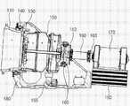
도 8은 본 발명의 다른 실시 예에 따른 풍력 발전 장치의 구성도이다. 도 8에 따른 풍력 발전 장치는 전면의 외부 면에 메인 베어링(240)이 설치되는 나셀 프레임(280), 나셀 프레임(280)의 전방에 구비되어 회전하는 로터허브(210), 메인 베어링(240)의 내 측면에 끼워 맞춤으로 부착되어 로터허브(210)로부터 발생하는 회전 토크를 전달하는 컨넥트(230,231), 컨넥트(230,231)의 후방에 연결되어 컨넥트(230,231)로부터 전달된 회전 속도를 증대시키는 증속기(250), 증속기(250)의 후방에 연결되어 회전토크를 전달받는 발전기(270)를 포함한다.8 is a configuration diagram of a wind turbine generator according to another embodiment of the present invention. The wind power generator according to FIG. 8 includes a
컨넥트는 나셀 프레임(280) 내측에서 메인 베어링(240)에 끼워 맞춤으로 부착되고 증속기(250) 커버와 연결된 제1컨넥트(230)와 나셀 프레임(280) 외측에서 메인 베어링(240)에 끼워 맞춤으로 부착되고 로터허브(210)에 연결된 제2컨넥트(231)으로 구성된다. 제1컨넥트(230)와 제2컨넥트(231)는 로터허브(210)에서 발생한 회전토크를 증속기(250)에 전달하는 역할을 한다.The connector is fitted to the
도 8에 도시된 풍력 발전 장치의 제 1 컨넥트(230)의 내측에는 삽입홈(237)이 형성되어 있고, 로터허브(210)의 회전을 방지할 필요가 있는 경우 이를 제어하기 위하여 삽입홈(237)에 회전방지부재(235)를 설치할 수 있다.An
구체적으로 도 4에서 도시된 풍력 발전 장치와 대비하여 볼 때, 도 8의 풍력 발전 장치는 로터허브(210)의 회전을 방지하기 위하여 증속기(250) 후방의 출력축(253)과 발전기(270) 전방의 입력축(263) 사이에 브레이크부(265)를 설치하게 되는데, 증속기(250)의 유지/보수를 위한 분해/조립 시에는 브레이크부(265)가 정상적으로 로터허브(210)의 회전을 막을 수 없게 된다. 그러므로 브레이크부(265) 이외에 별도의 로터허브(210)의 회전을 막기 위한 회전방지부재(235)가 필요하게 된다. 회전방지부재(235)를 이용할 경우 풍력 발전 장치의 동력 전달계의 모든 구성품의 독립적인 유지/보수시 로터허브(210)의 회전을 막을 수 있다.Specifically, in comparison with the wind turbine shown in FIG. 4, the wind turbine of FIG. 8 includes an
또한, 더욱 큰 용량의 풍력 발전 장치를 제작할 경우 베어링 수급 등의 이유로 증속기(250) 커버를 회전하는 것이 불가능할 경우 제 2 컨넥트(231)의 후방에 추가적인 평판축(225)을 설치하고, 이를 이용하여 증속기(250)에 회전 토크를 전달해 주도록 할 수 있다.In addition, when manufacturing a larger capacity wind turbine, if it is impossible to rotate the
상기에서 설명한 풍력 발전 장치는 주로 해상에서 설치, 운용되고 있으며 나셀 프레임 내부에서 유동하는 공기가 외부 공기와의 접촉이 없고 내부 공기가 폐회 로 상태에서 유동 냉각되도록 별도의 냉각장치(미도시)를 더 구비할 수도 있음은 물론이다.The wind power generator described above is mainly installed and operated at sea, and a separate cooling device (not shown) is further provided so that the air flowing inside the nacelle frame does not come into contact with the outside air and the inside air flows and is cooled in a closed circuit. Of course, it can also be provided.
본 발명에 따른 풍력 발전 장치에 의하면 로터허브와 증속기 사이에 컨넥터를 구비하여 별도로 분해/조립을 가능하게 하고 이를 통해 제품의 내구성, 신뢰성 향상은 물론 유지/보수의 편의성을 높일 수 있다. 또한, 컨넥트를 이용하여 로터허브와 증속기를 직결하여 증속기의 입력단인 주축이 사라지게 되어 나셀 프레임 내부가 단순화되고 무게가 감소하게 되며 경량화된 증속기를 제공할 수 있다. 이로써 풍력 발전 장치의 생산 원가 절감 효과가 있음은 물론이다.According to the wind turbine generator according to the present invention, a connector is provided between the rotor hub and the speed increaser to enable separate disassembly / assembly, thereby improving durability, reliability, and convenience of maintenance / repair of the product. In addition, by connecting the rotor hub and the speed increaser directly by using a connector, the main shaft, which is the input terminal of the speed increaser, disappears, thereby simplifying the nacelle frame, reducing the weight, and providing a lighter speed increaser. This will of course reduce the production cost of the wind turbine.
이상에서 본 발명의 바람직한 실시 예에 대하여 설명하였으나, 본 발명은 상술한 특정의 실시 예에 한정되지 아니한다. 즉, 본 발명이 속하는 기술분야에서 통상의 지식을 가지는 자라면 첨부된 특허청구범위의 사상 및 범주를 일탈함이 없이 본 발명에 대한 다수의 변경 및 수정이 가능하며, 그러한 모든 적절한 변경 및 수정의 균등물들도 본 발명의 범위에 속하는 것으로 간주되어야 할 것이다.While preferred embodiments of the present invention have been described above, the present invention is not limited to the above-described specific embodiments. That is, those skilled in the art to which the present invention pertains can make many changes and modifications to the present invention without departing from the spirit and scope of the appended claims, and all such appropriate changes and modifications are possible. Equivalents should be considered to be within the scope of the present invention.
도 1은 종래의 풍력발전시스템의 구성도,1 is a configuration diagram of a conventional wind power generation system,
도 2는 종래의 다른 형태의 풍력발전시스템의 구성도,2 is a configuration diagram of another conventional wind power generation system,
도 3은 본 발명의 일 실시 예에 따른 풍력 발전 장치의 구성도,3 is a configuration diagram of a wind turbine generator according to an embodiment of the present invention;
도 4는 도 3의 풍력 발전 장치의 상세 측 단면도,4 is a detailed side cross-sectional view of the wind power generator of FIG. 3;
도 5는 도 4의 풍력 발전 장치에 대하여 방진 받침부(185)를 추가한 상태를 나타낸 상세 측 단면도,FIG. 5 is a detailed side cross-sectional view illustrating a state in which a
도 6은 도 4의 풍력 발전 장치에 대하여 지지구조물(190)을 변경한 상태를 나타낸 상세 측 단면도,6 is a detailed side cross-sectional view showing a state in which the
도 7은 도 4의 풍력 발전 장치에 대하여 방진장치(195)를 추가한 상태를 나타낸 상세 측 단면도 및,7 is a detailed side cross-sectional view showing a state in which the
도 8은 본 발명의 다른 실시 예에 따른 풍력 발전 장치의 구성도이다.8 is a configuration diagram of a wind turbine generator according to another embodiment of the present invention.
<도면의 주요 부분에 대한 부호의 설명><Explanation of symbols for the main parts of the drawings>
110, 210 : 로터허브 130, 230 : 제1컨넥터110, 210:
131, 231 : 제2컨넥터 140, 240 : 메인 베어링131, 231:
150, 250 : 증속기 153, 253 : 출력축150, 250:
160, 260 : 커플링 163, 263 : 입력축160, 260:
170, 270 : 발전기 180, 280 : 나셀 프레임170, 270:
190 : 지지구조물 195 : 받침대190: support structure 195: pedestal
225 : 평판축 235 : 회전방지부재225: flat plate shaft 235: rotation preventing member
237 : 삽입홈237: Insertion Groove
Claims (12)
Translated fromKoreanPriority Applications (1)
| Application Number | Priority Date | Filing Date | Title |
|---|---|---|---|
| KR1020080062730AKR100999765B1 (en) | 2008-06-30 | 2008-06-30 | Wind power generator |
Applications Claiming Priority (1)
| Application Number | Priority Date | Filing Date | Title |
|---|---|---|---|
| KR1020080062730AKR100999765B1 (en) | 2008-06-30 | 2008-06-30 | Wind power generator |
Publications (2)
| Publication Number | Publication Date |
|---|---|
| KR20100002727Atrue KR20100002727A (en) | 2010-01-07 |
| KR100999765B1 KR100999765B1 (en) | 2010-12-08 |
Family
ID=41812726
Family Applications (1)
| Application Number | Title | Priority Date | Filing Date |
|---|---|---|---|
| KR1020080062730AActiveKR100999765B1 (en) | 2008-06-30 | 2008-06-30 | Wind power generator |
Country Status (1)
| Country | Link |
|---|---|
| KR (1) | KR100999765B1 (en) |
Cited By (4)
| Publication number | Priority date | Publication date | Assignee | Title |
|---|---|---|---|---|
| KR102082490B1 (en)* | 2018-12-04 | 2020-02-27 | 두산중공업 주식회사 | Multi type wind turbine |
| KR102203750B1 (en)* | 2020-01-14 | 2021-01-15 | 주식회사 금풍 | A wind turbine with a generator support structure |
| CN113847358A (en)* | 2021-08-24 | 2021-12-28 | 太原重工股份有限公司 | Coupling protection casing device |
| CN114448168A (en)* | 2022-03-14 | 2022-05-06 | 常州优谷新能源科技股份有限公司 | 15MW half-direct-drive generator |
Family Cites Families (2)
| Publication number | Priority date | Publication date | Assignee | Title |
|---|---|---|---|---|
| JP2003214325A (en)* | 2002-01-28 | 2003-07-30 | Ebara Corp | Wind power generating device |
| KR100752510B1 (en)* | 2006-04-14 | 2007-08-29 | 유니슨 주식회사 | Wind generators with single main bearing |
- 2008
- 2008-06-30KRKR1020080062730Apatent/KR100999765B1/enactiveActive
Cited By (5)
| Publication number | Priority date | Publication date | Assignee | Title |
|---|---|---|---|---|
| KR102082490B1 (en)* | 2018-12-04 | 2020-02-27 | 두산중공업 주식회사 | Multi type wind turbine |
| KR102203750B1 (en)* | 2020-01-14 | 2021-01-15 | 주식회사 금풍 | A wind turbine with a generator support structure |
| CN113847358A (en)* | 2021-08-24 | 2021-12-28 | 太原重工股份有限公司 | Coupling protection casing device |
| CN113847358B (en)* | 2021-08-24 | 2023-09-29 | 太原重工股份有限公司 | Coupler protective cover device |
| CN114448168A (en)* | 2022-03-14 | 2022-05-06 | 常州优谷新能源科技股份有限公司 | 15MW half-direct-drive generator |
Also Published As
| Publication number | Publication date |
|---|---|
| KR100999765B1 (en) | 2010-12-08 |
Similar Documents
| Publication | Publication Date | Title |
|---|---|---|
| US8147183B2 (en) | Drivetrain for generator in wind turbine | |
| US8951162B1 (en) | Drive train transmission | |
| CN105240216B (en) | Improved structure of compact wind generating set | |
| WO2015101288A1 (en) | Integrated semi-direct-drive wind turbine transmission chain and gear box used thereby | |
| US20170175717A1 (en) | Wind turbine with a modular drive train | |
| JP2008546948A (en) | Wind generator with single main bearing | |
| US20110143880A1 (en) | Drivetrain for generator in wind turbine | |
| CN103375349B (en) | Driving chain of wind generating set and wind power generating set | |
| EP3640473B1 (en) | Transmission system for semi-direct wind power generating set | |
| JP2000337245A (en) | Wind power generator | |
| US9297364B2 (en) | Bogie plate for wind turbine | |
| AU2010317918A1 (en) | Wind turbine | |
| CN101198790A (en) | Wind turbine | |
| US20120091725A1 (en) | Wind turbine generator | |
| EP2604857B1 (en) | A modular gear unit for a wind turbine | |
| CN202560942U (en) | Wind power speed-up box of composite planetary transmission mechanism | |
| CN202194785U (en) | Horizontal shaft wind turbine unit and gear box device thereof | |
| KR100999765B1 (en) | Wind power generator | |
| JP5148346B2 (en) | Wind power generator | |
| US20210017966A1 (en) | Drive train arrangement | |
| CN205117615U (en) | An Improved Structure of a Compact Wind Power Generating Set | |
| CN103216400A (en) | A semi-direct drive wind power transmission system | |
| CN101476545A (en) | Wind generator set | |
| US9447777B2 (en) | Continuous-flow power installation | |
| CN203248322U (en) | A semi-direct drive wind power transmission system |
Legal Events
| Date | Code | Title | Description |
|---|---|---|---|
| A201 | Request for examination | ||
| PA0109 | Patent application | St.27 status event code:A-0-1-A10-A12-nap-PA0109 | |
| PA0201 | Request for examination | St.27 status event code:A-1-2-D10-D11-exm-PA0201 | |
| R18-X000 | Changes to party contact information recorded | St.27 status event code:A-3-3-R10-R18-oth-X000 | |
| D13-X000 | Search requested | St.27 status event code:A-1-2-D10-D13-srh-X000 | |
| D14-X000 | Search report completed | St.27 status event code:A-1-2-D10-D14-srh-X000 | |
| PG1501 | Laying open of application | St.27 status event code:A-1-1-Q10-Q12-nap-PG1501 | |
| E902 | Notification of reason for refusal | ||
| PE0902 | Notice of grounds for rejection | St.27 status event code:A-1-2-D10-D21-exm-PE0902 | |
| E13-X000 | Pre-grant limitation requested | St.27 status event code:A-2-3-E10-E13-lim-X000 | |
| P11-X000 | Amendment of application requested | St.27 status event code:A-2-2-P10-P11-nap-X000 | |
| P13-X000 | Application amended | St.27 status event code:A-2-2-P10-P13-nap-X000 | |
| R18-X000 | Changes to party contact information recorded | St.27 status event code:A-3-3-R10-R18-oth-X000 | |
| E701 | Decision to grant or registration of patent right | ||
| PE0701 | Decision of registration | St.27 status event code:A-1-2-D10-D22-exm-PE0701 | |
| GRNT | Written decision to grant | ||
| PR0701 | Registration of establishment | St.27 status event code:A-2-4-F10-F11-exm-PR0701 | |
| PR1002 | Payment of registration fee | St.27 status event code:A-2-2-U10-U11-oth-PR1002 Fee payment year number:1 | |
| PG1601 | Publication of registration | St.27 status event code:A-4-4-Q10-Q13-nap-PG1601 | |
| PN2301 | Change of applicant | St.27 status event code:A-5-5-R10-R13-asn-PN2301 St.27 status event code:A-5-5-R10-R11-asn-PN2301 | |
| R18-X000 | Changes to party contact information recorded | St.27 status event code:A-5-5-R10-R18-oth-X000 | |
| R18-X000 | Changes to party contact information recorded | St.27 status event code:A-5-5-R10-R18-oth-X000 | |
| FPAY | Annual fee payment | Payment date:20130904 Year of fee payment:4 | |
| PR1001 | Payment of annual fee | St.27 status event code:A-4-4-U10-U11-oth-PR1001 Fee payment year number:4 | |
| R18-X000 | Changes to party contact information recorded | St.27 status event code:A-5-5-R10-R18-oth-X000 | |
| FPAY | Annual fee payment | Payment date:20140917 Year of fee payment:5 | |
| PR1001 | Payment of annual fee | St.27 status event code:A-4-4-U10-U11-oth-PR1001 Fee payment year number:5 | |
| FPAY | Annual fee payment | Payment date:20150909 Year of fee payment:6 | |
| PR1001 | Payment of annual fee | St.27 status event code:A-4-4-U10-U11-oth-PR1001 Fee payment year number:6 | |
| FPAY | Annual fee payment | Payment date:20160907 Year of fee payment:7 | |
| PR1001 | Payment of annual fee | St.27 status event code:A-4-4-U10-U11-oth-PR1001 Fee payment year number:7 | |
| P22-X000 | Classification modified | St.27 status event code:A-4-4-P10-P22-nap-X000 | |
| FPAY | Annual fee payment | Payment date:20170907 Year of fee payment:8 | |
| PR1001 | Payment of annual fee | St.27 status event code:A-4-4-U10-U11-oth-PR1001 Fee payment year number:8 | |
| P22-X000 | Classification modified | St.27 status event code:A-4-4-P10-P22-nap-X000 | |
| PR1001 | Payment of annual fee | St.27 status event code:A-4-4-U10-U11-oth-PR1001 Fee payment year number:9 | |
| FPAY | Annual fee payment | Payment date:20190930 Year of fee payment:10 | |
| PR1001 | Payment of annual fee | St.27 status event code:A-4-4-U10-U11-oth-PR1001 Fee payment year number:10 | |
| PR1001 | Payment of annual fee | St.27 status event code:A-4-4-U10-U11-oth-PR1001 Fee payment year number:11 | |
| PR1001 | Payment of annual fee | St.27 status event code:A-4-4-U10-U11-oth-PR1001 Fee payment year number:12 | |
| PN2301 | Change of applicant | St.27 status event code:A-5-5-R10-R13-asn-PN2301 St.27 status event code:A-5-5-R10-R11-asn-PN2301 | |
| PR1001 | Payment of annual fee | St.27 status event code:A-4-4-U10-U11-oth-PR1001 Fee payment year number:13 | |
| PR1001 | Payment of annual fee | St.27 status event code:A-4-4-U10-U11-oth-PR1001 Fee payment year number:14 | |
| P22-X000 | Classification modified | St.27 status event code:A-4-4-P10-P22-nap-X000 | |
| PR1001 | Payment of annual fee | St.27 status event code:A-4-4-U10-U11-oth-PR1001 Fee payment year number:15 | |
| R18-X000 | Changes to party contact information recorded | St.27 status event code:A-5-5-R10-R18-oth-X000 | |
| PR1001 | Payment of annual fee | St.27 status event code:A-4-4-U10-U11-oth-PR1001 Fee payment year number:16 |