KR20090131384A - Gas injection assembly and thin film deposition apparatus using the same - Google Patents
Gas injection assembly and thin film deposition apparatus using the sameDownload PDFInfo
- Publication number
- KR20090131384A KR20090131384AKR1020080057220AKR20080057220AKR20090131384AKR 20090131384 AKR20090131384 AKR 20090131384AKR 1020080057220 AKR1020080057220 AKR 1020080057220AKR 20080057220 AKR20080057220 AKR 20080057220AKR 20090131384 AKR20090131384 AKR 20090131384A
- Authority
- KR
- South Korea
- Prior art keywords
- gas
- heater
- shower head
- substrate
- reactor
- Prior art date
- Legal status (The legal status is an assumption and is not a legal conclusion. Google has not performed a legal analysis and makes no representation as to the accuracy of the status listed.)
- Granted
Links
Images


Classifications
- C—CHEMISTRY; METALLURGY
- C23—COATING METALLIC MATERIAL; COATING MATERIAL WITH METALLIC MATERIAL; CHEMICAL SURFACE TREATMENT; DIFFUSION TREATMENT OF METALLIC MATERIAL; COATING BY VACUUM EVAPORATION, BY SPUTTERING, BY ION IMPLANTATION OR BY CHEMICAL VAPOUR DEPOSITION, IN GENERAL; INHIBITING CORROSION OF METALLIC MATERIAL OR INCRUSTATION IN GENERAL
- C23C—COATING METALLIC MATERIAL; COATING MATERIAL WITH METALLIC MATERIAL; SURFACE TREATMENT OF METALLIC MATERIAL BY DIFFUSION INTO THE SURFACE, BY CHEMICAL CONVERSION OR SUBSTITUTION; COATING BY VACUUM EVAPORATION, BY SPUTTERING, BY ION IMPLANTATION OR BY CHEMICAL VAPOUR DEPOSITION, IN GENERAL
- C23C16/00—Chemical coating by decomposition of gaseous compounds, without leaving reaction products of surface material in the coating, i.e. chemical vapour deposition [CVD] processes
- C23C16/44—Chemical coating by decomposition of gaseous compounds, without leaving reaction products of surface material in the coating, i.e. chemical vapour deposition [CVD] processes characterised by the method of coating
- C23C16/455—Chemical coating by decomposition of gaseous compounds, without leaving reaction products of surface material in the coating, i.e. chemical vapour deposition [CVD] processes characterised by the method of coating characterised by the method used for introducing gases into reaction chamber or for modifying gas flows in reaction chamber
- C23C16/45563—Gas nozzles
- C23C16/4557—Heated nozzles
- C—CHEMISTRY; METALLURGY
- C23—COATING METALLIC MATERIAL; COATING MATERIAL WITH METALLIC MATERIAL; CHEMICAL SURFACE TREATMENT; DIFFUSION TREATMENT OF METALLIC MATERIAL; COATING BY VACUUM EVAPORATION, BY SPUTTERING, BY ION IMPLANTATION OR BY CHEMICAL VAPOUR DEPOSITION, IN GENERAL; INHIBITING CORROSION OF METALLIC MATERIAL OR INCRUSTATION IN GENERAL
- C23C—COATING METALLIC MATERIAL; COATING MATERIAL WITH METALLIC MATERIAL; SURFACE TREATMENT OF METALLIC MATERIAL BY DIFFUSION INTO THE SURFACE, BY CHEMICAL CONVERSION OR SUBSTITUTION; COATING BY VACUUM EVAPORATION, BY SPUTTERING, BY ION IMPLANTATION OR BY CHEMICAL VAPOUR DEPOSITION, IN GENERAL
- C23C16/00—Chemical coating by decomposition of gaseous compounds, without leaving reaction products of surface material in the coating, i.e. chemical vapour deposition [CVD] processes
- C23C16/44—Chemical coating by decomposition of gaseous compounds, without leaving reaction products of surface material in the coating, i.e. chemical vapour deposition [CVD] processes characterised by the method of coating
- C23C16/455—Chemical coating by decomposition of gaseous compounds, without leaving reaction products of surface material in the coating, i.e. chemical vapour deposition [CVD] processes characterised by the method of coating characterised by the method used for introducing gases into reaction chamber or for modifying gas flows in reaction chamber
- C23C16/45563—Gas nozzles
- C23C16/45565—Shower nozzles
Landscapes
- Chemical & Material Sciences (AREA)
- General Chemical & Material Sciences (AREA)
- Chemical Kinetics & Catalysis (AREA)
- Engineering & Computer Science (AREA)
- Materials Engineering (AREA)
- Mechanical Engineering (AREA)
- Metallurgy (AREA)
- Organic Chemistry (AREA)
- Chemical Vapour Deposition (AREA)
Abstract
Translated fromKoreanDescription
Translated fromKorean본 발명은, 반응기에 설치되어 가스를 반응기 내에 안착된 기판에 공급하면서, 공급되는 가스의 온도를 일정하게 유지시키기 위한 가스분사조립체 및 이러한 가스분사조립체가 구비된 박막증착장비에 관한 것으로서, 특히 하나의 반응기에서 복수의 기판이 함께 처리되도록 하는 데 사용되는 가스분사조립체 및 박막증착장치에 관한 것이다.The present invention relates to a gas spray assembly for maintaining a constant temperature of the supplied gas while supplying gas to a substrate seated in the reactor and a thin film deposition apparatus equipped with such a gas spray assembly. A gas spray assembly and a thin film deposition apparatus used to allow a plurality of substrates to be processed together in a reactor.
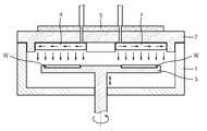
반도체 소자의 스케일이 점차 축소됨에 따라 극박막에 대한 요구가 갈수록 증대되고 있어 박막증착방법으로서 원자층증착(atomic layer deposition, ALD)방법이 각광받고 있다. 원자층증착방법은 기판에 각각의 원료가스들을 분리 공급하여 원료가스들의 표면 포화에 의해 박막이 형성되도록 하는 방법이다. 상기한 방식을 구현하기 위한 박막증착장치가 도 1에 도시되어 있다. 특히, 도 1에 도시된 종래의 박막증착장치는 하나의 반응기 내에서 여러 장의 기판을 동시에 원자층증착 가능한 형태이다.As the scale of semiconductor devices is gradually reduced, the demand for ultra-thin films is increasing. As a thin film deposition method, an atomic layer deposition (ALD) method is in the spotlight. The atomic layer deposition method is a method of separating and supplying each source gas to a substrate to form a thin film by surface saturation of the source gases. A thin film deposition apparatus for implementing the above scheme is shown in FIG. 1. In particular, the conventional thin film deposition apparatus illustrated in FIG. 1 is capable of atomic layer deposition of several substrates simultaneously in one reactor.
도 1을 참조하면, 종래의 박막증착장치(9)는 반응기(1)와, 반응기(1) 내부 공간을 개폐하는 탑리드(2)를 구비한다. 반응기(1) 내부 공간에는 원형의 회전플레이트(3)가 회전 및 승강가능하게 설치된다. 회전플레이트(3)의 상부에는 복수의 기판(w)이 원주방향을 따라 배치된다. 탑리드(2)의 하부에는 복수의 샤워헤드(4)가 설치된다. 외부로부터 유입된 가스는 샤워헤드(4)를 통해 기판(w)으로 공급된다. 예컨대, 복수의 샤워헤드(4)에서는 각각 제1원료가스, 퍼지가스, 제2원료가스, 퍼지가스를 공급할 수 있다. 회전플레이트(3)가 회전하면, 회전플레이트(3)에 안착된 기판(w)은 제1원료가스, 퍼지가스, 제2원료가스 및 퍼지가스를 순차적으로 공급받으면서 원자층 증착이 이루어진다.Referring to FIG. 1, the conventional thin film deposition apparatus 9 includes a
한편, 탑리드(2)의 상측에는 하나의 히터(5)가 배치되는데, 이 히터(5)는 복수의 샤워헤드(4) 전체 영역을 가열할 수 있는 발열영역을 가지고 있는데, 이 발열영역 전체의 온도가 동일하게 제어되므로 많은 문제가 발생한다. 이하, 상세히 살펴보기로 한다.On the other hand, one heater 5 is disposed above the
박막증착이 원활하게 이루어지기 위해서는 외부의 기화장치에 의하여 기화온도까지 가열되어 기체상태로 샤워헤드(4)로 유입된 원료가스가 샤워헤드(4) 내에서 기화된 상태를 유지하다가 반응기(1)로 공급된 후 다시 가열에 의하여 분해되어 기판(w)에 증착되는 것이다. 예컨대, Si 원료가 포함된 원료가스 SiH4는 기화되어 샤워헤드(4)로 유입되고, 샤워헤드(4) 내에서 기체상태를 유지하다가 반응기(1) 내로 공급된 후 분해온도까지 가열되면서, 기판(w)과 반응하여 Si와 H4로 분해되어, Si는 기판에 증착되고 H4는 반응기(1)로부터 배출되는 것이다. 이에 샤워헤드(4) 내의 온도가 기화온도 이하로 냉각되어 원료가스가 응축되거나 또는 분해온도 이상으로 가열되어 원료가스가 분해되는 것을 방지하기 위해서는 샤워헤드(4) 내부가 적정한 온도를 유지하여야 하는데, 히터(5)는 이렇게 샤워헤드(4) 내의 가스가 적정한 온도를 유지할 수 있게 하는 작용을 한다.In order to smoothly deposit the thin film, the raw material gas heated to the vaporization temperature by an external vaporization device and introduced into the
문제는 여러 장의 기판을 동시에 처리하는 형태의 종래의 박막증착장치에서는 서로 다른 종류의 복수의 원료가스가 사용되며, 원료가스별로 기화온도와 분해온도가 상이하기 때문에, 복수의 샤워헤드(4)가 동일한 온도로 제어되는 경우 원료가스에 따라서 샤워헤드 내에서 응축 또는 분해가 발생할 수 있다는 것이다. 예컨대, 박막증착을 위하여 서로 다른 종류의 원료1과 원료2를 사용한다고 했을 때, 원료1의 기화온도는 100℃이며 분해온도는 150℃이고, 원료2의 기화온도는 200℃이고 분해온도는 300℃이다. 히터(5)로 복수의 샤워헤드(4)를 130℃로 가열하는 경우, 원료1의 경우 샤워헤드(4)내에서 기체상태를 유지할 수 있지만, 200℃ 이상으로 가열 및 기화되어 샤워헤드(4)로 유입된 원료2는 샤워헤드 내에서 기화온도 이하로 냉각되어 응축됨으로써 파티클이 발생된다. 역으로, 샤워헤드(4) 내의 온도를 200℃ 이상으로 유지하는 경우 원료1이 샤워헤드 내에서 분해되어 파티클이 발생된다.The problem is that in the conventional thin film deposition apparatus that processes several sheets at the same time, a plurality of different kinds of source gases are used, and since the vaporization temperature and the decomposition temperature are different for each source gas, the plurality of
종래의 박막증착장치(9)에서는 이상에서 설명한 바와 같이 하나의 히터(5)에 의하여 발열영역 전체(복수의 샤워헤드)가 동일한 온도로 제어되기 때문에 파티클에 의한 오염 등의 문제가 발생하였다. 파티클에 의하여 박막증착장치(9) 내부가 오염되면 증착된 박막의 품질이 저하될 뿐만 아니라 설비안정성도 보장하지 못한다는 문제점이 있다.In the conventional thin film deposition apparatus 9, as described above, the entire heating region (plural showerheads) is controlled by the same heater 5, so that problems such as contamination due to particles have occurred. If the inside of the thin film deposition apparatus 9 is contaminated by particles, the quality of the deposited thin film is not only degraded, but also there is a problem in that it does not guarantee equipment stability.
본 발명은 상기한 문제점을 해결하기 위한 것으로서, 원료가스별로 별도의 온도제어가 가능하여 파티클 발생을 억제할 수 있도록 구조가 개선된 가스분사조립체 및 이를 이용한 박막증착장치를 제공하는데 있다.The present invention is to solve the above problems, to provide a gas spray assembly and a thin film deposition apparatus using the same structure is improved so that it is possible to separate the temperature control for each source gas to suppress the generation of particles.
상기 목적을 달성하기 위한 본 발명에 따른 가스분사조립체는, 기판이 장착되는 반응기를 밀폐하기 위한 탑리드, 상기 탑리드의 둘레 방향을 따라 복수 개 배치되어 상기 탑리드에 결합되는 것으로서, 가스가 유입되는 가스유입공과, 상기 가스유입공으로 유입된 가스가 확산되는 가스확산공간 및 상기 가스확산공간에서 확산된 가스가 상기 기판으로 분사되기 위한 다수의 가스분사공이 형성되어 있는 샤워헤드 및 상기 샤워헤드로 유입된 가스를 가열하기 위한 것으로서, 상기 복수의 샤워헤드가 배치된 전체 영역 중 상호 구획된 적어도 2개의 영역이 독립적으로 온도제어되도록 하는 가열수단을 구비하는 것에 특징이 있다.Gas injection assembly according to the present invention for achieving the above object, a plurality of top lids for sealing the reactor in which the substrate is mounted, arranged in the circumferential direction of the top lead is coupled to the top lead, the gas flows in A shower head and a shower head having a gas inlet hole, a gas diffusion space into which the gas introduced into the gas inlet hole is diffused, and a plurality of gas injection holes for injecting the gas diffused from the gas diffusion space into the substrate are formed. In order to heat the gas, it is characterized in that it comprises heating means for independently controlling the temperature of at least two mutually partitioned regions among the entire regions in which the plurality of shower heads are arranged.
본 발명에 따르면, 상기 가열수단은 상기 복수의 샤워헤드 중 적어도 2개의 샤워헤드의 상측에 각각 설치되어 상기 샤워헤드로 유입된 가스를 가열하며, 상호 독립적으로 온도제어 가능한 히터인 것이 바람직하다.According to the present invention, the heating means is respectively installed on the upper side of at least two shower heads of the plurality of shower heads to heat the gas introduced into the shower head, it is preferable that the heater independently temperature control.
본 발명에 따르면, 상기 히터의 열손실을 방지하도록 상기 히터의 상측에 절연체가 설치되는 것이 바람직하며, 상기 히터로부터 발생된 열이 상기 탑리드를 통해 전달되지 않도록, 상기 히터와 탑리드 사이에는 절연체가 개재되는 것이 더욱 바람직하다.According to the present invention, it is preferable that an insulator is installed on the upper side of the heater to prevent heat loss of the heater, and insulator is provided between the heater and the top lead so that heat generated from the heater is not transmitted through the top lead. It is more preferable to interpose.
또한, 상기한 목적을 달성하기 위한 본 발명에 따른 박막증착장치는, 내부에 반응공간을 형성하는 반응기, 상기 탑리드와 상대 회전가능하도록 상기 반응기 내부에 설치되며, 기판이 안착되는 복수의 기판안착부가 상면에 형성되어 있는 기판지지부 및 상기한 구성의 가스분사조립체를 구비하는 것에 특징이 있다.In addition, the thin film deposition apparatus according to the present invention for achieving the above object, a reactor for forming a reaction space therein, a plurality of substrates are installed inside the reactor so as to be relatively rotatable with the top lead, the substrate is seated It is characterized by including the substrate support part formed in the additional upper surface, and the gas injection assembly of the said structure.
본 발명에 따른 가스분사조립체 및 이를 이용한 박막증착장치에서는 서로 독립적으로 동작하는 복수의 히터를 구비하여 가스의 온도를 개별적으로 제어할 수 있으므로 가스의 응축 또는 분해로 인한 파티클의 발생을 억제할 수 있고, 결과적으로 증착되는 박막의 품질이 향상되며 설비안정성이 향상된다는 장점이 있다.In the gas spray assembly and the thin film deposition apparatus using the same according to the present invention, a plurality of heaters operating independently of each other can be used to individually control the temperature of the gas, thereby preventing generation of particles due to condensation or decomposition of the gas. As a result, the quality of the deposited thin film is improved and facility stability is improved.
또한, 본 발명에 따른 가스분사조립체 및 이를 이용한 박막증착장치에서는 히터의 열이 손실되는 것을 방지하여 열효율이 증대되는 장점이 있다.In addition, the gas spray assembly and the thin film deposition apparatus using the same according to the present invention has the advantage that the thermal efficiency is increased by preventing the heat of the heater to be lost.
이하, 첨부된 도면을 참조하여, 본 발명의 바람직한 실시예에 따른 가스분사조립체(80)와 박막증착장치(100)를 설명한다. 본 발명에 따른 가스분사조립체(80)는 박막증착장치(100)에 포함되는 구성이므로 박막증착장치(100)를 설명하면서 가스분사조립체(80)도 함께 설명하기로 한다.Hereinafter, with reference to the accompanying drawings, a
도 2는 본 발명의 바람직한 실시예에 따른 박막증착장치(100)의 개략적 단면도이며, 도 3은 도 2에 도시된 박막증착장치의 주요 부분에 대한 분리 사시도이고, 도 4는 도 2의 Ⅳ-Ⅳ선 개략적 단면도이며, 도 5는 도 2의 Ⅴ-Ⅴ선 개략적 단면도 이다.2 is a schematic cross-sectional view of a thin
도 2 내지 도 5를 참조하면, 본 발명의 바람직한 실시예에 따른 박막증착장치(100)는 반응기(10), 기판지지부(20) 및 가스분사조립체(80)를 구비한다.2 to 5, the thin
반응기(10)는 바닥부(11)와 외벽부(12)를 구비한다. 바닥부(11)는 원판의 형상으로 이루어져 있고, 외벽부(12)는 바닥부(111)의 가장자리로부터 상방으로 수직하게 연장 형성되어 폐곡면 형상으로 이루어져 있다. 그리고 외벽부(12)에는 기판(w)이 출입하는 게이트밸브(도면 미도시)가 형성되어 있다. 후술할 가스분사조립체(80)가 반응기(10)의 상부에 결합되면 반응기(10)의 내부에는 반응공간(16)이 형성되며, 반응공간(16)에서 기판(w)에 대한 박막증착이 이루어진다. 또한, 이 반응공간(16)은 진공으로 유지되어야 하므로, 외부로부터 공기가 유입되는 것을 방지하도록 가스분사조립체(80)의 하면과 반응기(10)의 상면 사이에는 오링(O-ring, 미도시) 등과 같은 밀폐부재가 개재된다.The
그리고 반응기(10) 내부에 잔존하는 불필요 가스 및 파티클을 배출하기 위한 배기수단이 반응기(10)에 마련되는데, 후술할 기판지지부(20)와 반응기의 외벽부의 내면 사이에 환형의 배기덕트(미도시)가 설치되는 것이 바람직하다. 이 배기덕트(미도시)는 배기구를 통해 배기펌프(미도시)와 연결되어 반응기(10) 내의 불필요 가스를 강제 배기시키게 된다.In addition, an exhaust means for discharging unnecessary gas and particles remaining in the
기판지지부(20)는 반응기(10) 내에서 기판(w)을 지지하여 회전시키기 위한 것으로서 내부의 반응공간(16)에 설치되며, 서셉터(21), 기판안착부(22), 샤프트(23) 및 히팅수단(도면 미도시)를 구비한다.The substrate support
서셉터(21)는 원판의 형상으로 반응기(10) 내부에 회전 가능하게 배치되어 있다. 서셉터(21)에는 기판(w)을 안착시키기 위하여 오목하게 형성된 기판안착부(22)가 복수 개, 특히 본 실시예에서는 6개 마련된다. 도 5에 도시된 바와 같이, 기판안착부(22)들은 기판지지부(20) 상면의 둘레방향을 따라 소정의 각도 간격으로 상호 이격되게 배치된다. 샤프트(23)의 양단부 중 일단부는 서셉터(21)의 하면과 결합되어 있고, 타단부는 반응기(10)를 관통하여 모터 등과 같은 회전수단(미도시)과 연결되어 있다. 따라서 샤프트(23)가 회전하면 서셉터(21)가 회전 중심축(A)을 중심으로 회전하게 된다. 또한 샤프트(23)는 모터 및 볼스크류 조립체(미도시) 등과 같은 승강수단과 연결되어 있어, 샤프트(23)의 승강시 서셉터(21)도 함께 승강된다. 서셉터(21)의 하부에는 기판(w)을 가열하기 위한 히팅수단(미도시)이 매설되어 있다.The
가스분사조립체(80)는 탑리드(30), 복수의 샤워헤드(40) 및 적어도 2개의 히터(50)를 구비한다.The
탑리드(30)는 반응기(10)의 내부 즉 반응공간(16)을 개폐하기 위한 것으로서 탑플레이트의 역할을 수행하며 탑리드(30)가 반응공간(16)을 폐쇄하는 경우 이 반응공간은 밀폐된다. 탑리드(30)는 반응기(10)의 상부에 결합되는데, 착탈되는 방식으로 결합될 수도 있으나 본 실시예에서는 힌지가능하게 결합된다. 탑리드(30)는 반응기(10)의 형상과 대응되도록 대략 원형으로 형성된다.The
또한, 탑리드(30)에는 그 중심점을 기준으로 원주 방향을 따라 복수의 장착공(31)이 방사형으로 배치된다. 장착공(31)은 탑리드(30)의 상면과 하면 사이를 관통하여 형성되는데, 이 장착공(31)은 후술할 샤워헤드(40)가 설치되는 곳으로서 대략 원호형으로 이루어진다. 본 실시예에서는 8개의 장착공(31)이 일정한 각도 간격을 유지하면서 배치되어 있다. 또한 탑리드(30)의 중앙부에도 샤워헤드(예컨대, 퍼지가스 분사용 샤워헤드)를 장착할 필요가 있는 경우 장착공(미도시)을 형성할 수도 있으며, 중앙에 배치되는 장착공은 원형으로 형성된다. 또한, 증착공정에 따라 장착공의 크기가 서로 다르게 형성될 수도 있을 뿐만 아니라 장착공의 개수도 다르게 될 수 있다. 즉, 어떠한 막을 증착하는가에 따라 장착공의 크기, 개수가 다르게 될 수 있다.In addition, a plurality of mounting
샤워헤드(40)는 외부로부터 가스를 도입하여 반응기(10) 내에 장착된 기판(w)에 가스를 분사하기 위한 것으로서, 탑리드(30)에 마련된 각각의 장착공(31)에 삽입되어 설치된다. 샤워헤드(40)로 도입되는 가스는 원료가스, 반응가스, 퍼지가스 및 식각가스 등 적용하는 공정에 따라 다양하게 조합될 수 있다.The
샤워헤드(40)의 상부에는 상기한 바와 같이 다양한 가스를 샤워헤드(40)의 내측으로 도입하기 위한 가스유입공(42)이 형성되며, 이 가스유입공(42)은 불활성 가스 탱크 등 외부의 공급장치(미도시)와 연결되어 있다. 특히, 원료를 공급하는 원료공급장치와 가스유입공(42) 사이에는 이 원료를 기체상태로 상변화시키기 위한 기화장치가 개재되는 것이 일반적이다.A
한편, 샤워헤드(40)를 통해 기판(w)으로 가스가 공급될 때 기판(w)의 전체 영역에 걸쳐 가스가 고르게 유입되는 것이 바람직하며, 특정 영역으로 편중되어 가스가 도입되는 것은 막의 균일도를 저하시켜 바람직하지 못하다. 이에, 가스가 기 판(w)의 전체 영역에 고르게 유입될 수 있도록 샤워헤드(40)에는 가스확산공간(41)과 다수의 가스분사공(43)이 형성되어 있다. 즉, 가스유입공(42)을 통해 유입된 가스는 가스확산공간(41)을 통해 샤워헤드(40)의 전체로 넓게 확산되고, 이렇게 확산된 가스는 샤워헤드(40)의 하면 전체 영역에 걸쳐 고르게 형성되어 있는 가스분사공(43)을 통해 기판(w)의 전체 영역으로 고르게 분사된다. 본 실시예에서 8개의 장착공(31)이 배치되어 있는 바, 8개의 샤워헤드(40)가 설치되는 것으로 설명 및 도시하였으나, 반드시 이에 한정되는 것은 아니며, 처리공정에 따라 달라질 수 있음은 자명하다.On the other hand, when the gas is supplied to the substrate w through the
히터(50)는 샤워헤드(40) 내의 가스 특히, 원료가스를 가열하여 이들 가스가 일정한 온도로 유지될 수 있도록 하기 위한 것으로서 샤워헤드(40)의 상측에 설치되는데, 본 발명에서는 히터(50)가 적어도 2개 마련된다. 두 개의 히터(50)는 각각 독립적으로 온도제어된다. 본 실시예에서는 독립된 2개의 히터가 마련된 것으로 설명하였으나 하나의 히터 내에서 발열영역을 적어도 2개로 구획하여 발열량을 서로 독립적으로 제어할 수도 있다. 즉, 본 발명에서의 히터는 복수의 샤워헤드가 배치된 영역을 적어도 2개의 영역으로 구획하고, 그 구획된 영역을 서로 다르게 가열하여 독립적으로 온도제어할 수 있는 가열수단의 일 예에 불과하며, 복수의 히터를 설치하는 이외의 다른 수단도 상기한 바와 같이 구획된 영역을 독립적 온도제어하는 기능을 수행한다면 본 발명의 가열수단으로 채용될 수 있다.The
종래의 박막증착장치에서는 하나의 히터를 이용하여 모든 샤워헤드를 가열하였기 때문에 모든 샤워헤드가 동일한 온도로 형성됨으로써, 가스의 종류에 따라 일 부의 가스는 샤워헤드 내에서 응축되거나 분해되는 등의 문제가 발생하였는 바, 본 발명에서는 원료가스가 유입되는 샤워헤드(40)마다 별도의 히터(50)를 설치하여 원료가스별로 독립적으로 온도제어를 가능케 하였다. 이에, 종래의 박막증착장치와 같이 샤워헤드 내에서 파티클이 발생하여 장치가 오염되는 등의 문제가 발생하지 않게 된다. 히터(50)의 개수는 공정에 사용되는 가스의 개수와 종류에 따라, 보다 정확하게는 가스들의 기화온도 및 분해온도에 따라 다르게 될 수 있다.In the conventional thin film deposition apparatus, since all the shower heads are heated by using one heater, all the shower heads are formed at the same temperature, so that some gases may be condensed or decomposed in the shower head depending on the type of gas. In the present invention, a
한편, 히터(50)로부터 발생된 열이 가스를 가열하는데 사용되지 못하고 외부로 방출됨으로써 열효율이 저하되는 것을 방지할 필요가 있다. 이에 본 발명에 따른 가스분사조립체(80)에서는 두 개의 절연체(61,62)를 구비한다. 즉, 히터(50)의 상측으로 열이 방출되는 것을 방지하도록, 히터(50)의 상부는 제1절연체(61)에 의하여 감싸져 있다. 또한, 히터(50)로부터 탑리드(30)로 전달되는 것을 방지하도록 히터(50)와 탑리드(30) 사이에도 제2절연체(62)가 개재된다. 보다 정확하게 설명하면, 히터(50)로부터 샤워헤드(40)로 전달된 열이 탑리드(30)로 전달되는 것을 방지하고자, 탑리드(30)와 샤워헤드(40) 사이에 제2절연체(62)가 구비된다. 탑리드(30)는 열전달율이 우수한 금속 소재로 이루어지는 것이 일반적이므로 제2절연체(62)를 설치하여 히터(50)의 열효율을 증대시킬 수 있다.On the other hand, the heat generated from the
이하, 상기한 구성으로 이루어진 박막증착장치(100)의 사용예 및 동작에 대하여 설명하기로 한다. 본 사용예는 기판(w)에 SrTiO3막을 증착하는데 사용되는 경우이다. 상기한 막을 형성하기 위하여, 8개의 샤워헤드(40)가 배치된다. 8개의 샤워헤드 중 Sr을 포함하는 제1원료가스, O3반응가스, Ti를 포함하는 제2원료가스, O3반응가스가 서로 이격되어 4개 배치되고, 이들 사이에는 N2나 Ar 등의 퍼지가스가 공급되는 4개의 샤워헤드로 이루어진다.Hereinafter, a use example and operation of the thin
Sr이 포함된 제1원료가스는 다양한 형태일 수 있으나 본 사용예에서는 대략 기화상태를 유지하는 안정온도가 250℃ ~ 300℃이다. Ti를 포함하는 제2원료가스는 150℃ ~ 200℃가 기화상태를 유지하는 온도이며, 분해온도는 대략 250℃이다. 반응가스인 O3의 경우 온도가 상승하면 O2로 환원되어 반응성이 떨어지게 되므로 온도상승을 억제해야 한다.The first raw material gas containing Sr may be in various forms, but in this use example, the stable temperature maintaining the vaporization state is approximately 250 ° C. to 300 ° C. The second raw material gas containing Ti is a temperature at which 150 ° C to 200 ° C maintains a vaporized state, and a decomposition temperature is approximately 250 ° C. In the case of O3 which is a reaction gas, when the temperature rises, it is reduced to
상기한 원료가스의 특성에 따라, 제1원료가스가 유입되는 샤워헤드와 제2원료가스가 유입되는 샤워헤드는 서로 독립적으로 온도제어되어야 하는 바, 독립적으로 운전되는 히터가 각 샤워헤드 위에 배치된다. 그러나, 반응가스가 유입되는 샤워헤드에는 가열이 요구되지 않으므로 히터가 배치될 필요가 없고, 퍼지가스가 유입되는 샤워헤드에도 히터가 배치될 필요가 없다. 이에 본 사용예에서는 2개의 히터가 사용된다.According to the characteristics of the raw material gas, the shower head in which the first raw material gas is introduced and the shower head in which the second raw material gas is introduced should be temperature controlled independently of each other, and an independent heater is disposed on each shower head. . However, since the heating is not required in the shower head into which the reaction gas is introduced, the heater does not need to be disposed, and the heater does not need to be disposed in the shower head into which the purge gas is introduced. In this use example, two heaters are used.
상기한 구성으로 이루어진 장치가 작동하면, 8개의 샤워헤드에서는 각각 가스를 계속적으로 공급하며, 서셉터(31)는 복수의 기판(w)이 장착된 상태로 회전하게 된다. 기판(w)의 상면은 제1원료가스, 반응가스, 제2원료가스, 반응가스에 노출되면서 박막증착이 이루어진다. 제1원료가스가 공급되는 샤워헤드의 상부에 배치된 히터는 250℃ ~ 300℃가 유지될 수 있도록 발열되며, 제2원료가스가 공급되는 샤워헤드의 상부에 배치된 히터는 150℃ ~ 200℃가 유지될 수 있도록 발열된다. 이에 따라, 제1원료가스와 제2원료가스 및 반응가스는 샤워헤드 내에서 응축되거나 분해되지 않고 기화된 상태를 안정적으로 유지할 수 있다.When the device having the above-described configuration operates, the eight showerheads continuously supply gas, respectively, and the
지금까지 가스분사조립체(80)에 장착공(31)이 형성되고, 샤워헤드(40)는 장착공(31)에 삽입설치되는 것으로 설명 및 도시하였으나, 가스분사조립체(80)의 형태는 위와 같은 형태로 한정되는 것이 아니라 다양한 변형이 가능하다. 이러한 변형된 실시예가 도 6에 도시되어 있다. 도 6은 본 발명의 다른 실시예에 따른 가스분사조립체를 설명하기 위한 개략적 도면이다.Although the mounting
도 6을 참조하면, 탑리드(30)에는 위에서 설명한 실시예와 달리 장착공이 형성되어 있지 않고, 탑리드(30)의 하면에는 제1장착부(35)가 오목하게 형성되어 있으며, 탑리드(30)의 상면에는 제2장착부(36)가 오목하게 형성되어 있다. 제1,2장착부(35,36)는 모두 탑리드(30)의 중심부로부터 둘레방향을 따라 방사형으로 8개씩 배치된다. 제1장착부(36)에는 샤워헤드(40)가 설치되며, 제2장착부(35)에는 히터(50)와 제1절연체(61)가 설치된다. 샤워헤드(40)의 가스유입공(42)으로 가스를 도입하기 위하여, 제1절연체(61), 히터(50) 및 탑리드(30)를 관통하여 가스도입로가 형성되며, 이 가스도입로는 가스유입공(42)과 연통되는 구성으로 되어 있다. 도 6에 도시된 각 구성요소들 중 위에서 설명한 실시예에서 동일한 참조번호가 부여된 것은 그 구성 및 작용효과가 동일하므로 설명을 생략하기로 한다.Referring to FIG. 6, unlike the above-described embodiment, the mounting hole is not formed in the
본 발명은 첨부된 도면에 도시된 일 실시예를 참고로 설명되었으나 이는 예시적인 것에 불과하며, 당해 기술분야에서 통상의 지식을 가진 자라면 이로부터 다 양한 변형 및 균등한 타 실시예가 가능하다는 점을 이해할 수 있을 것이다. 따라서, 본 발명의 진정한 보호 범위는 첨부된 청구 범위에 의해서만 정해져야 할 것이다.Although the present invention has been described with reference to one embodiment shown in the accompanying drawings, this is merely exemplary, and various modifications and equivalent other embodiments are possible to those skilled in the art. I can understand. Accordingly, the true scope of protection of the invention should be defined only by the appended claims.
도 1은 종래의 박막증착장치를 설명하기 위한 개략적 단면도이다.1 is a schematic cross-sectional view for explaining a conventional thin film deposition apparatus.
도 2는 본 발명의 바람직한 실시예에 따른 박막증착장치(100)의 개략적 단면도이다.2 is a schematic cross-sectional view of a thin
도 3은 도 2에 도시된 박막증착장치의 주요 부분에 대한 분리 사시도이다.3 is an exploded perspective view of the main part of the thin film deposition apparatus shown in FIG.
도 4는 도 2의 Ⅳ-Ⅳ선 개략적 단면도이다.4 is a schematic cross-sectional view taken along the line IV-IV of FIG. 2.
도 5는 도 2의 Ⅴ-Ⅴ선 개략적 단면도이다.FIG. 5 is a schematic cross-sectional view taken along the line VV of FIG. 2.
도 6은 본 발명의 다른 실시예에 따른 가스분사조립체를 설명하기 위한 개략적 도면이다.6 is a schematic view for explaining a gas injection assembly according to another embodiment of the present invention.
<도면의 주요 부분에 대한 부호의 설명><Explanation of symbols for the main parts of the drawings>
100 ... 박막증착장치 10 ... 반응기100 ... thin
20 ... 기판지지부 21 ... 서셉터20 ...
30 ... 탑리드 40 ... 샤워헤드30 ...
50 ... 히터 61 ... 제1절연체50 ...
62 ... 제2절연체 80 ... 가스분사조립체62 ...
w ... 기판w ... PCB
Claims (7)
Translated fromKoreanPriority Applications (1)
| Application Number | Priority Date | Filing Date | Title |
|---|---|---|---|
| KR1020080057220AKR101412034B1 (en) | 2008-06-18 | 2008-06-18 | Gas injection assembly and thin film deposition apparatus using the same |
Applications Claiming Priority (1)
| Application Number | Priority Date | Filing Date | Title |
|---|---|---|---|
| KR1020080057220AKR101412034B1 (en) | 2008-06-18 | 2008-06-18 | Gas injection assembly and thin film deposition apparatus using the same |
Publications (2)
| Publication Number | Publication Date |
|---|---|
| KR20090131384Atrue KR20090131384A (en) | 2009-12-29 |
| KR101412034B1 KR101412034B1 (en) | 2014-06-26 |
Family
ID=41690605
Family Applications (1)
| Application Number | Title | Priority Date | Filing Date |
|---|---|---|---|
| KR1020080057220AActiveKR101412034B1 (en) | 2008-06-18 | 2008-06-18 | Gas injection assembly and thin film deposition apparatus using the same |
Country Status (1)
| Country | Link |
|---|---|
| KR (1) | KR101412034B1 (en) |
Cited By (5)
| Publication number | Priority date | Publication date | Assignee | Title |
|---|---|---|---|---|
| KR101588269B1 (en)* | 2014-08-05 | 2016-01-28 | (주)동원파츠 | Gas distributor |
| US20170069470A1 (en)* | 2014-05-12 | 2017-03-09 | Tokyo Electron Limited | Upper electrode structure of plasma processing apparatus, plasma processing apparatus, and operation method therefor |
| WO2020056413A1 (en)* | 2018-09-14 | 2020-03-19 | Applied Materials, Inc. | Segmented showerhead for uniform delivery of multiple precursors |
| WO2020247966A1 (en)* | 2019-06-07 | 2020-12-10 | Lam Research Corporation | Independently adjustable flowpath conductance in multi-station semiconductor processing |
| JP2022534383A (en)* | 2019-05-31 | 2022-07-29 | アプライド マテリアルズ インコーポレイテッド | Method and system for forming films on substrates |
Families Citing this family (2)
| Publication number | Priority date | Publication date | Assignee | Title |
|---|---|---|---|---|
| KR101729491B1 (en)* | 2014-12-19 | 2017-05-02 | 주식회사 테스 | Showerhead |
| WO2020251696A1 (en) | 2019-06-10 | 2020-12-17 | Applied Materials, Inc. | Processing system for forming layers |
Family Cites Families (3)
| Publication number | Priority date | Publication date | Assignee | Title |
|---|---|---|---|---|
| JP4121269B2 (en)* | 2001-11-27 | 2008-07-23 | 日本エー・エス・エム株式会社 | Plasma CVD apparatus and method for performing self-cleaning |
| JP4288036B2 (en)* | 2002-02-20 | 2009-07-01 | 東京エレクトロン株式会社 | Gas shower head, film forming apparatus and film forming method |
| JP4463583B2 (en) | 2004-02-13 | 2010-05-19 | 東京エレクトロン株式会社 | Film forming method and film forming apparatus |
- 2008
- 2008-06-18KRKR1020080057220Apatent/KR101412034B1/enactiveActive
Cited By (11)
| Publication number | Priority date | Publication date | Assignee | Title |
|---|---|---|---|---|
| US20170069470A1 (en)* | 2014-05-12 | 2017-03-09 | Tokyo Electron Limited | Upper electrode structure of plasma processing apparatus, plasma processing apparatus, and operation method therefor |
| KR101588269B1 (en)* | 2014-08-05 | 2016-01-28 | (주)동원파츠 | Gas distributor |
| WO2020056413A1 (en)* | 2018-09-14 | 2020-03-19 | Applied Materials, Inc. | Segmented showerhead for uniform delivery of multiple precursors |
| KR20210043732A (en)* | 2018-09-14 | 2021-04-21 | 어플라이드 머티어리얼스, 인코포레이티드 | Split type showerhead for uniform delivery of multiple precursors |
| CN112740386A (en)* | 2018-09-14 | 2021-04-30 | 应用材料公司 | Segmented Sprinklers for Uniform Delivery of Multiple Precursors |
| JP2021536531A (en)* | 2018-09-14 | 2021-12-27 | アプライド マテリアルズ インコーポレイテッドApplied Materials, Incorporated | Segmented shower head for uniform supply of multiple precursors |
| US11834743B2 (en) | 2018-09-14 | 2023-12-05 | Applied Materials, Inc. | Segmented showerhead for uniform delivery of multiple precursors |
| TWI825173B (en)* | 2018-09-14 | 2023-12-11 | 美商應用材料股份有限公司 | A showerhead assembly and a method of introducing precursors through a segmented showerhead |
| US12043895B2 (en) | 2018-09-14 | 2024-07-23 | Applied Materials, Inc. | Methods of using a segmented showerhead for uniform delivery of multiple pre-cursors |
| JP2022534383A (en)* | 2019-05-31 | 2022-07-29 | アプライド マテリアルズ インコーポレイテッド | Method and system for forming films on substrates |
| WO2020247966A1 (en)* | 2019-06-07 | 2020-12-10 | Lam Research Corporation | Independently adjustable flowpath conductance in multi-station semiconductor processing |
Also Published As
| Publication number | Publication date |
|---|---|
| KR101412034B1 (en) | 2014-06-26 |
Similar Documents
| Publication | Publication Date | Title |
|---|---|---|
| US8123860B2 (en) | Apparatus for cyclical depositing of thin films | |
| US8197599B2 (en) | Gas head and thin-film manufacturing apparatus | |
| US9435026B2 (en) | Film deposition apparatus | |
| US6040011A (en) | Substrate support member with a purge gas channel and pumping system | |
| US20030198754A1 (en) | Aluminum oxide chamber and process | |
| JP5619164B2 (en) | CVD method and CVD reactor | |
| US7579276B2 (en) | Substrate processing apparatus and method of manufacturing semiconductor device | |
| US7648578B1 (en) | Substrate processing apparatus, and method for manufacturing semiconductor device | |
| KR101412034B1 (en) | Gas injection assembly and thin film deposition apparatus using the same | |
| KR20050016156A (en) | Apparatus of manufacturing thin film and method for manufacturing thin film | |
| US7462245B2 (en) | Single-wafer-processing type CVD apparatus | |
| US20180350562A1 (en) | Deposition radial and edge profile tenability through independent control of teos flow | |
| US20250146173A1 (en) | Epi isolation plate and parallel block purge flow tuning for growth rate and uniformity | |
| US20150368830A1 (en) | One-piece injector assembly and one-piece exhaust liner | |
| JP5139107B2 (en) | Vapor growth equipment | |
| US10718051B2 (en) | Methods for chemical vapor deposition (CVD) in a movable liner assembly | |
| KR101324208B1 (en) | Substrate processing apparatue | |
| JP2006032459A (en) | Chemical vapor phase growing device | |
| US20250320628A1 (en) | Epi isolation plate and parallel block purge flow tuning for growth rate and uniformity | |
| KR100820347B1 (en) | Gas injection device and substrate processing apparatus having the same | |
| JPH01297820A (en) | Apparatus and method for applying film to board | |
| CN113166940A (en) | CVD reactor with gas inlet means covered by shield plate means | |
| KR20070073390A (en) | Semiconductor manufacturing equipment | |
| JP2002275634A (en) | Method for manufacturing semiconductor device | |
| KR20000066722A (en) | Lower electrode part of cvd apparatus |
Legal Events
| Date | Code | Title | Description |
|---|---|---|---|
| PA0109 | Patent application | Patent event code:PA01091R01D Comment text:Patent Application Patent event date:20080618 | |
| PG1501 | Laying open of application | ||
| N231 | Notification of change of applicant | ||
| PN2301 | Change of applicant | Patent event date:20110117 Comment text:Notification of Change of Applicant Patent event code:PN23011R01D | |
| A201 | Request for examination | ||
| PA0201 | Request for examination | Patent event code:PA02012R01D Patent event date:20130305 Comment text:Request for Examination of Application Patent event code:PA02011R01I Patent event date:20080618 Comment text:Patent Application | |
| E902 | Notification of reason for refusal | ||
| PE0902 | Notice of grounds for rejection | Comment text:Notification of reason for refusal Patent event date:20140206 Patent event code:PE09021S01D | |
| E701 | Decision to grant or registration of patent right | ||
| PE0701 | Decision of registration | Patent event code:PE07011S01D Comment text:Decision to Grant Registration Patent event date:20140613 | |
| GRNT | Written decision to grant | ||
| PR0701 | Registration of establishment | Comment text:Registration of Establishment Patent event date:20140619 Patent event code:PR07011E01D | |
| PR1002 | Payment of registration fee | Payment date:20140620 End annual number:3 Start annual number:1 | |
| PG1601 | Publication of registration | ||
| FPAY | Annual fee payment | Payment date:20170322 Year of fee payment:4 | |
| PR1001 | Payment of annual fee | Payment date:20170322 Start annual number:4 End annual number:4 | |
| FPAY | Annual fee payment | Payment date:20190311 Year of fee payment:6 | |
| PR1001 | Payment of annual fee | Payment date:20190311 Start annual number:6 End annual number:6 | |
| FPAY | Annual fee payment | Payment date:20200309 Year of fee payment:7 | |
| PR1001 | Payment of annual fee | Payment date:20200309 Start annual number:7 End annual number:7 | |
| PR1001 | Payment of annual fee | Payment date:20210310 Start annual number:8 End annual number:8 | |
| PR1001 | Payment of annual fee | Payment date:20240312 Start annual number:11 End annual number:11 |