KR20090127234A - Charging system, vehicle applied to the charging system, and charge controller - Google Patents
Charging system, vehicle applied to the charging system, and charge controllerDownload PDFInfo
- Publication number
- KR20090127234A KR20090127234AKR1020090049784AKR20090049784AKR20090127234AKR 20090127234 AKR20090127234 AKR 20090127234AKR 1020090049784 AKR1020090049784 AKR 1020090049784AKR 20090049784 AKR20090049784 AKR 20090049784AKR 20090127234 AKR20090127234 AKR 20090127234A
- Authority
- KR
- South Korea
- Prior art keywords
- charging
- vehicle
- control means
- battery
- charge
- Prior art date
- Legal status (The legal status is an assumption and is not a legal conclusion. Google has not performed a legal analysis and makes no representation as to the accuracy of the status listed.)
- Ceased
Links
- 238000004891communicationMethods0.000claimsdescription18
- 238000000034methodMethods0.000claimsdescription14
- 230000000977initiatory effectEffects0.000claims1
- 238000007599dischargingMethods0.000description10
- 238000010586diagramMethods0.000description8
- 230000005540biological transmissionEffects0.000description3
- 238000012790confirmationMethods0.000description3
- 230000005856abnormalityEffects0.000description1
Images


Classifications
- B—PERFORMING OPERATIONS; TRANSPORTING
- B60—VEHICLES IN GENERAL
- B60L—PROPULSION OF ELECTRICALLY-PROPELLED VEHICLES; SUPPLYING ELECTRIC POWER FOR AUXILIARY EQUIPMENT OF ELECTRICALLY-PROPELLED VEHICLES; ELECTRODYNAMIC BRAKE SYSTEMS FOR VEHICLES IN GENERAL; MAGNETIC SUSPENSION OR LEVITATION FOR VEHICLES; MONITORING OPERATING VARIABLES OF ELECTRICALLY-PROPELLED VEHICLES; ELECTRIC SAFETY DEVICES FOR ELECTRICALLY-PROPELLED VEHICLES
- B60L53/00—Methods of charging batteries, specially adapted for electric vehicles; Charging stations or on-board charging equipment therefor; Exchange of energy storage elements in electric vehicles
- B60L53/10—Methods of charging batteries, specially adapted for electric vehicles; Charging stations or on-board charging equipment therefor; Exchange of energy storage elements in electric vehicles characterised by the energy transfer between the charging station and the vehicle
- B60L53/14—Conductive energy transfer
- H—ELECTRICITY
- H02—GENERATION; CONVERSION OR DISTRIBUTION OF ELECTRIC POWER
- H02J—CIRCUIT ARRANGEMENTS OR SYSTEMS FOR SUPPLYING OR DISTRIBUTING ELECTRIC POWER; SYSTEMS FOR STORING ELECTRIC ENERGY
- H02J7/00—Circuit arrangements for charging or depolarising batteries or for supplying loads from batteries
- H02J7/14—Circuit arrangements for charging or depolarising batteries or for supplying loads from batteries for charging batteries from dynamo-electric generators driven at varying speed, e.g. on vehicle
- B—PERFORMING OPERATIONS; TRANSPORTING
- B60—VEHICLES IN GENERAL
- B60L—PROPULSION OF ELECTRICALLY-PROPELLED VEHICLES; SUPPLYING ELECTRIC POWER FOR AUXILIARY EQUIPMENT OF ELECTRICALLY-PROPELLED VEHICLES; ELECTRODYNAMIC BRAKE SYSTEMS FOR VEHICLES IN GENERAL; MAGNETIC SUSPENSION OR LEVITATION FOR VEHICLES; MONITORING OPERATING VARIABLES OF ELECTRICALLY-PROPELLED VEHICLES; ELECTRIC SAFETY DEVICES FOR ELECTRICALLY-PROPELLED VEHICLES
- B60L50/00—Electric propulsion with power supplied within the vehicle
- B60L50/50—Electric propulsion with power supplied within the vehicle using propulsion power supplied by batteries or fuel cells
- H—ELECTRICITY
- H02—GENERATION; CONVERSION OR DISTRIBUTION OF ELECTRIC POWER
- H02J—CIRCUIT ARRANGEMENTS OR SYSTEMS FOR SUPPLYING OR DISTRIBUTING ELECTRIC POWER; SYSTEMS FOR STORING ELECTRIC ENERGY
- H02J7/00—Circuit arrangements for charging or depolarising batteries or for supplying loads from batteries
- B—PERFORMING OPERATIONS; TRANSPORTING
- B60—VEHICLES IN GENERAL
- B60L—PROPULSION OF ELECTRICALLY-PROPELLED VEHICLES; SUPPLYING ELECTRIC POWER FOR AUXILIARY EQUIPMENT OF ELECTRICALLY-PROPELLED VEHICLES; ELECTRODYNAMIC BRAKE SYSTEMS FOR VEHICLES IN GENERAL; MAGNETIC SUSPENSION OR LEVITATION FOR VEHICLES; MONITORING OPERATING VARIABLES OF ELECTRICALLY-PROPELLED VEHICLES; ELECTRIC SAFETY DEVICES FOR ELECTRICALLY-PROPELLED VEHICLES
- B60L2270/00—Problem solutions or means not otherwise provided for
- B60L2270/30—Preventing theft during charging
- B60L2270/36—Preventing theft during charging of vehicles
- Y—GENERAL TAGGING OF NEW TECHNOLOGICAL DEVELOPMENTS; GENERAL TAGGING OF CROSS-SECTIONAL TECHNOLOGIES SPANNING OVER SEVERAL SECTIONS OF THE IPC; TECHNICAL SUBJECTS COVERED BY FORMER USPC CROSS-REFERENCE ART COLLECTIONS [XRACs] AND DIGESTS
- Y02—TECHNOLOGIES OR APPLICATIONS FOR MITIGATION OR ADAPTATION AGAINST CLIMATE CHANGE
- Y02T—CLIMATE CHANGE MITIGATION TECHNOLOGIES RELATED TO TRANSPORTATION
- Y02T10/00—Road transport of goods or passengers
- Y02T10/60—Other road transportation technologies with climate change mitigation effect
- Y02T10/70—Energy storage systems for electromobility, e.g. batteries
- Y—GENERAL TAGGING OF NEW TECHNOLOGICAL DEVELOPMENTS; GENERAL TAGGING OF CROSS-SECTIONAL TECHNOLOGIES SPANNING OVER SEVERAL SECTIONS OF THE IPC; TECHNICAL SUBJECTS COVERED BY FORMER USPC CROSS-REFERENCE ART COLLECTIONS [XRACs] AND DIGESTS
- Y02—TECHNOLOGIES OR APPLICATIONS FOR MITIGATION OR ADAPTATION AGAINST CLIMATE CHANGE
- Y02T—CLIMATE CHANGE MITIGATION TECHNOLOGIES RELATED TO TRANSPORTATION
- Y02T10/00—Road transport of goods or passengers
- Y02T10/60—Other road transportation technologies with climate change mitigation effect
- Y02T10/7072—Electromobility specific charging systems or methods for batteries, ultracapacitors, supercapacitors or double-layer capacitors
- Y—GENERAL TAGGING OF NEW TECHNOLOGICAL DEVELOPMENTS; GENERAL TAGGING OF CROSS-SECTIONAL TECHNOLOGIES SPANNING OVER SEVERAL SECTIONS OF THE IPC; TECHNICAL SUBJECTS COVERED BY FORMER USPC CROSS-REFERENCE ART COLLECTIONS [XRACs] AND DIGESTS
- Y02—TECHNOLOGIES OR APPLICATIONS FOR MITIGATION OR ADAPTATION AGAINST CLIMATE CHANGE
- Y02T—CLIMATE CHANGE MITIGATION TECHNOLOGIES RELATED TO TRANSPORTATION
- Y02T90/00—Enabling technologies or technologies with a potential or indirect contribution to GHG emissions mitigation
- Y02T90/10—Technologies relating to charging of electric vehicles
- Y02T90/14—Plug-in electric vehicles
- Y—GENERAL TAGGING OF NEW TECHNOLOGICAL DEVELOPMENTS; GENERAL TAGGING OF CROSS-SECTIONAL TECHNOLOGIES SPANNING OVER SEVERAL SECTIONS OF THE IPC; TECHNICAL SUBJECTS COVERED BY FORMER USPC CROSS-REFERENCE ART COLLECTIONS [XRACs] AND DIGESTS
- Y02—TECHNOLOGIES OR APPLICATIONS FOR MITIGATION OR ADAPTATION AGAINST CLIMATE CHANGE
- Y02T—CLIMATE CHANGE MITIGATION TECHNOLOGIES RELATED TO TRANSPORTATION
- Y02T90/00—Enabling technologies or technologies with a potential or indirect contribution to GHG emissions mitigation
- Y02T90/10—Technologies relating to charging of electric vehicles
- Y02T90/16—Information or communication technologies improving the operation of electric vehicles
Landscapes
- Engineering & Computer Science (AREA)
- Power Engineering (AREA)
- Transportation (AREA)
- Mechanical Engineering (AREA)
- Life Sciences & Earth Sciences (AREA)
- Sustainable Development (AREA)
- Sustainable Energy (AREA)
- Charge And Discharge Circuits For Batteries Or The Like (AREA)
- Electric Propulsion And Braking For Vehicles (AREA)
- Remote Monitoring And Control Of Power-Distribution Networks (AREA)
- Secondary Cells (AREA)
Abstract
Translated fromKorean
Description
Translated fromKorean본 발명은, 차량에 설치된 배터리용 충전 시스템과, 이 충전 시스템에 적용되는 차량 및, 충전 컨트롤러에 관한 것이다.The present invention relates to a battery charging system installed in a vehicle, a vehicle applied to the charging system, and a charging controller.
일반 주택에서 얻을 수 있는 상용의(commercial) 전원을 이용하는 차량 배터리용 충전 시스템이 공지되어 있다. 일본공개특허공보 2008-61432호에는, 일 충전 시스템이 기재되어 있는 바, 이에 따르면, 차량 배터리의 충전을 제어하기 위한 전자제어장치(ECU)가 차량에 설치되어 있다. 차량 배터리의 충전시, 차량의 충전 커넥터가 충전 케이블을 통해 주택의 옥외 배전구(outlet)에 접속된다. 주택에는, 차량 배터리 충전시, ECU와의 통신(communication)을 통해 인증을 행하는 인증(ID) 박스가 설치되어 있다. ID 박스와 ECU 사이에서 인증이 성립될 경우, 충전이 허가된다. 또한, 이것은 차량 도난의 방지에도 유효하다.BACKGROUND OF THE INVENTION Charging systems for vehicle batteries using commercial power sources available in ordinary homes are known. Japanese Laid-Open Patent Publication No. 2008-61432 describes a charging system, whereby an electronic control unit (ECU) for controlling charging of a vehicle battery is provided in a vehicle. When charging the vehicle battery, the charging connector of the vehicle is connected to the outdoor outlet of the house through the charging cable. The home is provided with an authentication (ID) box which authenticates through communication with the ECU when the vehicle battery is being charged. If authentication is established between the ID box and the ECU, charging is allowed. This is also effective for preventing vehicle theft.
일본공개특허공보 평8-111909호에는, 다른 충전 시스템이 개시되어 있는 바, 이 충전시스템은 전기 자동차용의 배터리를 충전하는 충전기와, 차량 배터리의 충전상태에 따라 충전기를 제어하는 컨트롤 유닛을 갖는다. 상기 컨트롤 유닛은, 차 량 배터리의 충전상태에 따른 배터리 충전 시간을 결정하는 충전 시간 계산기와, 배터리 충전 완료 시각 과 충전 시간에 따른 충전 개시 시각을 결정하는 충전 개시시각 계산기 및, 산출된 충전 개시 시각에 배터리 충전을 개시하는 배터리 충전 액츄에이터를 갖는다.Japanese Laid-Open Patent Publication No. Hei 8-111909 discloses another charging system, which has a charger for charging a battery for an electric vehicle and a control unit for controlling the charger according to the state of charge of the vehicle battery. . The control unit includes a charge time calculator for determining a battery charge time according to the state of charge of the vehicle battery, a charge start time calculator for determining a battery charge completion time and a charge start time according to the charge time, and a calculated charge start time. Has a battery charging actuator to initiate battery charging.
상기 일본공개특허공보 2008-61432호에 개시된 충전 시스템에 따르면, 충전의 개시전에 충전 케이블이 접속된다. 따라서, 이 시스템에서는, 차량 사용자의 부재중에는, 배터리 충전을 개시할 수 없다. 즉, 사용자가 소망하는 시간에 배터리 충전을 행하지 못할 수 있다.According to the charging system disclosed in Japanese Patent Laid-Open No. 2008-61432, a charging cable is connected before the start of charging. Therefore, in this system, battery charging cannot be started in the absence of the vehicle user. That is, the user may not be able to charge the battery at a desired time.
또한, 일본공개특허공보 평8-111909호에 개시된 충전 시스템에 따르면, 차량에 설치되어 있는 컨트롤 유닛에 의해 전술한 충전 단계가 행해진다. 충전을 위한 다양한 설정을 주택에서 행할 수 있다면, 사용자의 편의성이 향상될 수 있다. 그러나, 주택과 차량 사이의 통신을 위한 장치를 늘리는 것은 바람직하지 않다.Further, according to the charging system disclosed in Japanese Patent Application Laid-open No. Hei 8-111909, the above-described charging step is performed by the control unit installed in the vehicle. If various settings for charging can be made in the house, the user's convenience can be improved. However, it is not desirable to increase the device for communication between the house and the vehicle.
본 발명은, 일반 주택의 상용의 전원을 이용하는 충전 시스템을 제공하고, 사용자가 소망하는 임의의 시간에 배터리 충전을 행할 수 있게 하기 위한 것이다.The present invention provides a charging system using a commercial power source for a general house, and enables the user to perform battery charging at any desired time.
본 발명에 따르면, 지상 건축물에서 얻을 수 있는 상용의 전원을 이용하여 차량 배터리를 충전하는 충전 시스템은, 충전기와, 전력선과, 시간 설정 유닛 및, 컨트롤 유닛을 구비한다. 상기 충전기는 차량에 장착되어 차량 배터리를 충전하 며, 상기 전력선은 상기 지상 건축물과 상기 차량을 접속한다. 상기 시간 설정 유닛은 배터리 충전을 개시하는 충전 개시 시각을 설정하며, 상기 컨트롤 유닛은 충전 개시 시각에 배터리 충전을 개시하는데 사용된다.According to the present invention, a charging system for charging a vehicle battery using a commercial power source obtained from a ground building includes a charger, a power line, a time setting unit, and a control unit. The charger is mounted in a vehicle to charge a vehicle battery, and the power line connects the ground building and the vehicle. The time setting unit sets a charging start time for starting battery charging, and the control unit is used to start battery charging at the charging start time.
본 발명의 여타의 실시형태와 이점은 본 발명의 원리를 예시하는, 첨부도면과 관련된 하기의 설명으로 부터 명확해 질 것이다.Other embodiments and advantages of the invention will be apparent from the following description taken in conjunction with the accompanying drawings, illustrating the principles of the invention.
(발명을 실시하기 위한 최량의 형태)(The best form to carry out invention)
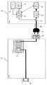
도 1은, 본 발명의 바람직한 실시예에 따른 충전 시스템의 구성을 나타내는 예시도이다. 도 1에는, 주택(10)등의 지상 건축물에서 얻을 수 있는 전원을 이용하여 차량(20)에 장착되어 있는 배터리를 충전하는 충전 시스템(1)이 나타나 있다. 상기 주택(10)은 지상 건축물에 상당한다.1 is an exemplary view showing a configuration of a charging system according to a preferred embodiment of the present invention. FIG. 1 shows a
주택(10)에는, 충전 컨트롤러(11)가 설치되어 있으며, 충전 컨트롤러(11)는, 시계(12)와, 입출력 장치(시간 설정 수단으로서의 시간 설정 유닛)(13)와, ECU(제어 수단으로서의 컨트롤 유닛 또는, 제1 제어수단으로서의 제1 컨트롤 유닛)(14) 및, 전력선 통신기(통신 수단으로서의 통신기)(15)를 구비한다.In the
시계(12)는 실시간 디지털 데이터를 출력한다. 입출력 장치(13)는 사용자 로 부터의 입력 데이터을 수신하는 입력부와, 배터리 충전에 필요한 출력 데이터를 출력하는 출력부를 갖는다. 입력부는 특정의 장치로 한정되는 것은 아니지만, 숫자 등을 입력하기 위한 버튼을 갖는 입력 장치라도 좋고, 터치 패널 장치라도 좋다. 또한, 출력부는, 예를 들면, 표시 장치로 형성된다. 사용자는, 이 입출력 장 치(13)를 이용하여, 충전 개시 시각을 포함하는 충전 개시 조건의 데이터를 설정할 수 있다.The
ECU(14)는 시계(12)로부터 실시간 디지털 데이터를 수신하며, 필요에 따라, 차량(20)에 설치되어 있는 충전 관리 컨트롤러(23)와 조합하여 충전 동작을 제어한다. 전력선 통신기(15)는, 전력선(40)을 통해 주택(10)과 차량(20) 사이의 통신을 제어한다. 또한, 전력선 통신기(15)는 주택(10)내의 배선구(31)에 접속된다.The ECU 14 receives real-time digital data from the
주택(10)에는, 복수개의 단자(T1, T2, …)를 갖는 분전반(switchboard; 30)이 설치되어, 주택(10)의 복수개의 배전구(31, 32, …)에 전력을 분배한다. 또한, 분전반(30)은 전력량계(33)를 통하여 상용의 전력선 망에 접속되어 있다.In the
배전구(31)는 주택(10) 내부에 배치되어, 분전반(30)의 단자(T1)에 접속되어 있다. 또한, 배전구(32)는, 주택(10)의 외부에 배치되어, 분전반(30)의 단자(T2)에 접속되어 있다. 단자(T1, T2)는, 분전반(30) 내부에서 서로 접속될 수도 있고, 절환기(switch;34)를 통하여 서로 접속될 수도 있다. 또한, 절환기(34)는 ECU(14)의 제어에 따라서, 분전반(30)의 단자간을 선택적으로 접속하도록 구성될 수도 있다.The
차량(20)은 시계(21)와, 입출력 장치(시간 설정 수단으로서의 시간 설정 유닛)(22)와, 충전 관리 컨트롤러(제어 수단으로서의 컨트롤 유닛 또는 제2 제어수단으로서의 제2 컨트롤 유닛)(23)와, 전력선 통신기(통신 수단으로서의 통신기)(24)와, 메인 배터리(25) 및, 충전및 방전기(충전기및 방전기)(26)를 갖는다. 차량(20)내의 시계(21)와, 입출력 장치(22)및, 전력선 통신기(24)는, 각각, 주택(10) 내의 시계(12)와, 입출력 장치(13)및, 전력선 통신기(15)와 실질적으로 동일하다.The
충전 관리 컨트롤러(23)는 차량(20)의 시계(21)로 부터 실시간 디지털 데이터를 수신하여, 출력 전압과 충전 수준등의 메인 배터리(25)의 상태를 모니터한다. 또한, 충전 관리 컨트롤러(23)는, 그 자체로, 또는 주택(10)의 ECU(14)와 조합하여, 충전 동작을 제어한다.The
충전및 방전기(26)는, 전력선(40)을 통해 공급되는 전력을 이용하여 메인 배터리(25)를 충전한다. 이 경우, 충전및 방전기(26)는 AC-DC 컨버터로서 동작한다. 또한, 충전및 방전기(26)는 메인 배터리(25)에 충전되어 있는 전력을, 전력선(40)을 통해 주택(10)에 공급할 수도 있다. 이 경우, 충전및 방전기(26)는 DC-AC 인버터로서 동작한다. 전력선(40)과 충전및 방전기(26)의 사이에는 스위치(27)가 배치되며, 스위치(27)의 동작은 충전 관리 컨트롤러(23)에 의해 제어된다. 또한, 스위치(27)는 충전및 방전기(26)에 내장될 수도 있다.The charging and
전력선(40)의 단부에는 전력 플러그(41)가 형성되어 있다. 또한, 메인 배터리(25)를 충전시키기 전 또는, 메인 배터리(25)에 충전되어 있는 전력을 주택(10)에 공급할 때는, 상기 전력 플러그(41)가 배전구(32)에 끼워진다.The
전술한 충전 시스템(1)에 있어서, 메인 배터리(25)를 충전할 때, 사용자는 입출력 장치(13 또는 22)를 통해 충전 개시 시각의 데이터를 포함한 충전 개시 조건의 데이터를 입력한다. 이어서, ECU(14)와 충전 관리 컨트롤러(23)는, 전력선 통신기(15, 24)를 통해 제어 데이터를 전송및 수신한다. 그리고, 충전 개시 조건이 충족되면, 충전 관리 컨트롤러(23)는 스위치(27)를 온 상태로 제어하며, 그에 따라 충전및 방전기(26)가 메인 배터리(25)의 충전을 개시한다. 또한, 전력선 통신기(15, 24)를 이용한 전력선 통신은 특정의 프로토콜(protocol)로 한정되는 것은 아니고, 임의의 공지된 프로토콜을 이용할 수도 있다.In the above-mentioned
전술한 바와 같이 구성된 충전 시스템(1)에 있어서, 충전 개시 조건의 데이터를 포함하는 충전 데이터는 주택(10)에서 설정될 수도 있고, 차량(20)에서 설정될 수도 있다. 이하에서는, 주택(10)에서 충전 데이터를 설정하는 경우의 구성 및 동작에 대해서 설명키로 한다.In the
도 2는 주택(10)에서 충전 데이터를 설정하는 경우의 충전 시스템의 구성을 나타내는 예시도이다. 이 구성의 충전 시스템에 있어서, 차량(20)은 입출력 장치(22)를 필요로 하지 않으며, 충전 시스템의 여타의 구성은 도 1을 참조로 앞에서 설명한 것과 실질적으로 동일하다.2 is an exemplary diagram illustrating a configuration of a charging system in the case of setting charging data in the
도 3은, 주택(10)에서 충전 데이터를 설정하는 경우의 본 발명의 바람직한 실시예에 따른 충전 시스템내의 동작단계를 나타내는 시퀀스도이다. 도 3에서는, 차량(20)이 충전을 위한 준비가 완료되어 있거나, 충전 관리 컨트롤러(23)와 전력선 통신기(24)가 동작 가능한 상태로 되어 있으며, 또한 전력선(40)의 전력 플러그(41)는 배전구(32)에 끼워져 있는 것으로 가정한다.3 is a sequence diagram showing an operation step in a charging system according to a preferred embodiment of the present invention when setting charging data in the
사용자는 충전 컨트롤러(11)내에 설치되어 있는 입출력 장치(13)를 통해 충전 동작의 데이터를 입력한다. 본 발명의 바람직한 실시예에 따른 충전 동작의 데이터는 하기와 같다.The user inputs data of the charging operation through the input /
(1) 충전 개시 시각(1) Charge start time
(2) 충전 종료 조건(2) Charging end condition
충전 종료 조건은 예를 들면, 메인 배터리(25)의 충전 수준(예를 들면, 만충전(full charge) 또는 90퍼센트 충전 등이다. 따라서, 메인 배터리(25)는 소망하는 수준까지 충전될 수 있다. 또한, 충전 종료 조건은 충전 종료 시각일 수도 있다. 이 경우, 전기 요금이 비교적 저렴한 심야에 충전을 행하도록 설정할 수도 있다.The charge termination condition is, for example, the level of charge of the main battery 25 (for example, full charge or 90 percent charge, etc.) Therefore, the
계속해서, 설정 데이터의 전송 단계가 다음과 같이 행해진다. 충전 컨트롤러(11)의 ECU(14)가 차량(20)의 충전 관리 컨트롤러(23)로 문의 신호(ENQ)를 송신하면, 충전 관리 컨트롤러(23)는 수령 신호(acnowledgement signal; ACK)를 반송한다. ECU(14)는 이 ACK를 수신하면 충전 제어 데이터를 송신한다. 충전 제어 데이터는, 도 4에 나타내는 바와 같이, 「충전/방전 플래그(flag)」, 「충전 개시 조건」, 「충전 종료 조건의 선택」및, 「충전 종료 조건」을 구비한다. 「충전/방전 플래그」는 충전 동작 또는 방전 동작 중 어느 쪽이 선택되어 있는지를 식별한다. 이하의 설명에서는 「충전」동작이 선택되어 있는 것으로 한다. 「충전 개시 조건」은 충전을 개시해야 할 시각을 지정한다. 「충전 종료 조건 선택」은 충전을 종료하는 조건으로서, 충전 수준과 충전 완료 시각 중 어느 쪽이 선택되어 있는지를 결정한다.Subsequently, the step of transferring the setting data is performed as follows. When the
충전 관리 컨트롤러(23)는 수신한 충전 제어 데이터를 메모리에 저장하고, 수령 신호(ACK)를 반송한다. 주택(10)의 ECU(14)는, 이 수령 신호(ACK)를 수신하면 전송 종료 신호(EOT)를 송신한다. 이에 따라, 설정 데이터 전송 단계가 종료된 다.The
전술한 설정 데이터의 전송 단계가 종료한 후, 충전 관리 컨트롤러(23)는 차량(20)의 시계(21)를 모니터한다. 「개시 조건」에 의해 지정된 충전 개시 시각이 도래하면, 충전 동작을 개시하기 전에 접속을 확인하는 단계가 다음과 같이 행해진다. 즉, 충전 관리 컨트롤러(23)는 문의 신호(ENQ)를 송신하고, ECU(14)는 수령 신호(ACK)를 반송한다. 충전 관리 컨트롤러(23)는 이 수령 신호(ACK)를 수신하면 충전 동작을 개시한다. 구체적으로, 충전 관리 컨트롤러(23)는 스위치(27)를 온 상태로 제어하여 충전및 방전기(26)를 기동(start)한다.After the above-described transmission of the setting data ends, the
충전 관리 컨트롤러(23)는 충전 동작중에, 충전 종료 조건이 충족되었는지 아닌지를 항상 모니터한다. 만일, 충전 종료 조건으로서 「만충전」이 지정되어 있는 경우에는, 메인 배터리(25)의 출력 전압을 모니터하여, 그 출력 전압이 「만충전」의 상태에 상당하는 수준까지 상승했을 경우, 배터리 충전을 정지한다. 이것은 스위치(27)를 오프 상태로 하여 충전및 방전기(26)를 정지함으로써 실현된다.The
또한, 충전 동작중, 접속을 확인하는 단계는 다음과 같이 행해진다. 충전 관리 컨트롤러(23)는 문의 신호(ENQ)를 송신하며, 이에 대해 ECU(14)는 수령 신호(ACK)를 반송한다. 이 후, 충전 관리 컨트롤러(23)는 주기적으로 충전중 데이터를 송신한다. 여기서의 충전중 데이터(charge-on data)는 충전및 방전기(26)가 메인 배터리(25)를 충전하고 있는 중임을 나타내는 데이터이다. 이어서, ECU(14)는 충전중 데이터를 수신할 때마다 수령 신호(ACK)를 반송한다. 이러한 접속 확인 단계에 의해, 충전 관리 컨트롤러(23)는, 주택(10)과 차량(20) 사이의 접속이 정상으 로 형성되어 있는지 아닌지를 확인할 수 있다. 만일, 전력선(40)의 전력 플러그(41)가 배전구(32)로부터 빠져 버려 있거나, 전력선(40)이 단선(disconnection)되어 있다면, 충전 관리 컨트롤러(23)는 수령 신호(ACK)를 수신할 수 없게 됨으로써 접속 이상(connection error)을 검출할 수 있다. 접속 이상이 검출되었을 경우, 충전 관리 컨트롤러(23)는 알람신호를 출력할 수도 있다.In the charging operation, the step of confirming the connection is performed as follows. The
본 발명의 바람직한 실시예의 충전 시스템(1)에 의하면, 충전을 위한 전력을 송전하는 전력선(40)을 통해, ECU(14)와 충전 관리 컨트롤러(23) 사이의 통신이 행해진다. 따라서, 전력선(40)을 통한 송전에 이상(error)이 생긴 경우, 충전 관리 컨트롤러(23)는 그 이상을 즉시 그리고 직접 검출할 수 있다. 또한, ECU(14) 및/또는 충전 관리 컨트롤러(23)는 충전 동작중의 접속 확인 단계의 로그(log)를 저장할 수도 있다.According to the
충전이 종료되면, 충전 관리 컨트롤러(23)는 문의 신호(ENQ)를 송신하고, ECU(14)는 수령 신호(ACK)를 반송한다. 계속해서, 충전 관리 컨트롤러(23)는, 충전이 완료된 것을 통지하는 충전 완료 데이터를 송신한다. ECU(14)는 충전 완료 데이터를 수신하고 수령 신호(ACK)를 반송한다. 또한, 충전 관리 컨트롤러(23)는 이 수령 신호를 수신하면, 전송 종료 신호(EOT)를 송신한다. 이에 따라, 일련의 충전 동작 단계가 종료된다.When the charge is completed, the
또한, 도 3의 시퀀스도에 나타낸 과정에 의하면, 차량(20)에 설치되는 충전 관리 컨트롤러(23)가 충전 개시 시각을 모니터하고 있지만, 본 발명은 이 단계에 한정되는 것은 아니다. 즉, 충전 개시 시각이 주택(10)의 충전 컨트롤러(11)로 입 력된 후, 충전 컨트롤러(11)가 실시간이 충전 개시 시각에 도래했는지 아닌지를 모니터하여, 충전 개시 시각이 도래했을 경우, 차량(20)에 신호를 보내 충전을 개시하도록 구성할 수도 있다.In addition, according to the process shown in the sequence diagram of FIG. 3, although the
메인 배터리(25)로부터 주택(10)으로 전력을 공급하는 방전 단계는 도 3의 시퀀스도에 의해 나타낸 단계와 실질적으로 동일하다. 단, 방전 단계에서는, 충전 관리 컨트롤러(23)가 충전및 방전기(26)를 DC-AC 인버터로서 동작시킨다. 또한, 충전 컨트롤러(11)는 메인 배터리(25)로부터 발생되는 전력을, 주택(10)내의 전기 기기와 배터리 등의 소망의 장치에 송전하도록, 절환기(34)의 동작을 제어하여 분전반(30)의 접속을 변화시킨다.The discharging step of supplying power from the
도 5는, 차량(20)에서 충전 데이터를 설정하는 경우의 충전 시스템의 구성을 나타내는 예시도이다. 이 경우, 주택(10)에는 충전 컨트롤러(11)를 설치하지 않아도 되며, 차량(20)에는 전력선 통신기(24)를 설치하지 않아도 된다. 도 5의 충전 시스템의 여타의 구성은 도 1을 참조하여 앞에서 설명한 것과 실질적으로 동일하다.5 is an exemplary diagram illustrating a configuration of a charging system in the case of setting charging data in the
도 6은, 차량(20)에서 충전 데이터를 설정하는 경우의 동작 단계를 나타내는 시퀀스도이다. 충전 관리 컨트롤러(23)의 동작은, 주택(10)에서 충전 데이터를 설정하는 경우와 실질적으로 동일하다. 충전 관리 컨트롤러(23)는 ECU(14)와 통신을 행할 필요가 없다. 하지만, 차량(20)에서 충전 데이터를 설정하는 경우, 주택(10)에 ECU(14)와 전력선 통신기(15)가 설치되고, 차량(20)에 전력선 통신기(24)를 장착하여, 충전 동작중에 접속 확인 단계를 행해도 좋다.6 is a sequence diagram showing an operation step in the case of setting charging data in the
전술한 바람직한 실시예에 따르면, 주택(10)과 차량(20)과의 사이는 전력선 통신에 의해 데이터가 송수신되고 있었지만, 본 발명은 이 구성으로만 한정되는 것은 아니다. 즉, 본 발명의 충전 시스템은, 도 7에 나타내는 바와 같이, 무선 통신으로 데이터의 송수신을 행할 수도 있다. 이 경우, 충전 컨트롤러(11)는 전력선 통신기(15) 대신에 무선 통신기(51)를 가지며, 차량(20)은 전력선 통신기(24) 대신에 무선 통신기(52)를 갖는다. 그러므로, 무선 통신기(51, 52) 사이에서 무선 신호가 송수신된다. 무선 통신의 프로토콜은 특별히 한정되는 것은 아니지만, 예를 들면, IEEE802.11 방식 또는, WiMax(Worldwide Interoperability for Microwave Access) 등을 이용할 수 있다.According to the above-described preferred embodiment, data has been transmitted and received between the
또한, 충전 또는 방전은 반드시 개시 시각을 설정할 필요는 없고, 즉석에서 충전 또는 방전을 개시시킬 수도 있다.In addition, charging or discharging does not necessarily need to set the start time, and it can also immediately start charging or discharging.
도 1은 본 발명의 바람직한 실시예에 따른 충전 시스템의 구성을 나타내는 예시도이다.1 is an exemplary view showing a configuration of a charging system according to a preferred embodiment of the present invention.
도 2는 주택에서 충전 데이터를 설정하는 경우의 본 발명의 바람직한 실시예에 따른 충전 시스템의 구성을 나타내는 예시도이다.2 is an exemplary view showing a configuration of a charging system according to a preferred embodiment of the present invention when setting charging data in a house.
도 3은 도 2의 동작 단계를 나타내는 시퀀스도이다.3 is a sequence diagram illustrating an operation step of FIG. 2.
도 4는 본 발명의 바람직한 실시예에 따른 충전 시스템내의 충전 제어 데이터의 일 예를 나타낸 것이다.4 shows an example of charging control data in a charging system according to a preferred embodiment of the present invention.
도 5는 차량에서 충전 데이터를 설정하는 경우의 본 발명의 바람직한 실시예에 따른 충전 시스템의 구성을 나타내는 예시도이다.5 is an exemplary view showing a configuration of a charging system according to a preferred embodiment of the present invention when setting charging data in a vehicle.
도 6은 도 5의 동작 단계를 나타내는 시퀀스도이다.6 is a sequence diagram illustrating an operation step of FIG. 5.
도 7은 본 발명의 다른 바람직한 실시예에 따른 충전 시스템의 구성을 나타내는 예시도이다.7 is an exemplary view showing a configuration of a charging system according to another preferred embodiment of the present invention.
(도면의 주요 부분에 대한 부호의 설명)(Explanation of symbols for the main parts of the drawing)
1 : 충전 시스템1: charging system
10 : 주택10: housing
11 : 충전 컨트롤러11: charge controller
12, 21 : 시계12, 21: clock
13, 22 : 입출력 장치13, 22: input and output device
14 : 전자제어장치(ECU)14: electronic control unit (ECU)
15, 24 : 전력선 통신기15, 24: power line communicator
20 : 차량20: vehicle
23 : 충전 관리 컨트롤러23: charge management controller
25 : 메인 배터리25: main battery
26 : 충전및 방전기26: charge and discharge
27 : 스위치27: switch
31, 32 : 배전구(outlet)31, 32: Outlet
40 : 전력선40: power line
51, 52 : 무선 통신기51, 52: wireless communicator
Claims (15)
Translated fromKoreanApplications Claiming Priority (2)
| Application Number | Priority Date | Filing Date | Title |
|---|---|---|---|
| JP2008149521AJP2009296824A (en) | 2008-06-06 | 2008-06-06 | Charging system |
| JPJP-P-2008-149521 | 2008-06-06 |
Publications (1)
| Publication Number | Publication Date |
|---|---|
| KR20090127234Atrue KR20090127234A (en) | 2009-12-10 |
Family
ID=41210773
Family Applications (1)
| Application Number | Title | Priority Date | Filing Date |
|---|---|---|---|
| KR1020090049784ACeasedKR20090127234A (en) | 2008-06-06 | 2009-06-05 | Charging system, vehicle applied to the charging system, and charge controller |
Country Status (6)
| Country | Link |
|---|---|
| US (1) | US8125183B2 (en) |
| EP (1) | EP2214287A2 (en) |
| JP (1) | JP2009296824A (en) |
| KR (1) | KR20090127234A (en) |
| AU (1) | AU2009202248B2 (en) |
| CA (1) | CA2668090A1 (en) |
Cited By (2)
| Publication number | Priority date | Publication date | Assignee | Title |
|---|---|---|---|---|
| KR101235516B1 (en)* | 2010-10-05 | 2013-02-20 | 엘에스산전 주식회사 | Apparatus and method for reducing power consumption in electric vehicle charging stand |
| US8610401B2 (en) | 2010-10-12 | 2013-12-17 | Hyundai Motor Company | Telematics device for remote charging control and method of providing service thereof |
Families Citing this family (58)
| Publication number | Priority date | Publication date | Assignee | Title |
|---|---|---|---|---|
| US8971057B2 (en) | 2009-03-25 | 2015-03-03 | Stem, Inc | Bidirectional energy converter with controllable filter stage |
| JP5493477B2 (en)* | 2009-06-02 | 2014-05-14 | 株式会社豊田自動織機 | Charging stand |
| US8350521B2 (en) | 2009-06-29 | 2013-01-08 | Stem, Inc. | High speed feedback adjustment of power charge/discharge from an energy storage system |
| WO2011008505A2 (en)* | 2009-06-29 | 2011-01-20 | Powergetics, Inc | High speed feedback adjustment of power charge/discharge from energy storage system |
| US8946924B2 (en)* | 2009-07-30 | 2015-02-03 | Lutron Electronics Co., Inc. | Load control system that operates in an energy-savings mode when an electric vehicle charger is charging a vehicle |
| US8473131B2 (en)* | 2009-09-28 | 2013-06-25 | Powerhydrant Llc | Method and system for charging electric vehicles |
| US20110145141A1 (en)* | 2009-10-02 | 2011-06-16 | James Blain | Method and apparatus for recharging electric vehicles |
| US8463453B2 (en) | 2009-11-13 | 2013-06-11 | Leviton Manufacturing Co., Inc. | Intelligent metering demand response |
| US8324761B2 (en) | 2009-11-13 | 2012-12-04 | Leviton Manufacturing Co., Inc. | Electrical switching module |
| US8755944B2 (en) | 2009-11-13 | 2014-06-17 | Leviton Manufacturing Co., Inc. | Electrical switching module |
| US8558504B2 (en) | 2010-01-11 | 2013-10-15 | Leviton Manufacturing Co., Inc. | Electric vehicle supply equipment with timer |
| US20110169447A1 (en) | 2010-01-11 | 2011-07-14 | Leviton Manufacturing Co., Inc. | Electric vehicle supply equipment |
| EP2525466B1 (en)* | 2010-01-13 | 2020-03-11 | Panasonic Corporation | Electric power supply device and vehicle charge system |
| JP2011164771A (en)* | 2010-02-05 | 2011-08-25 | Motion:Kk | Server and system for operation management of charging station |
| US8841881B2 (en) | 2010-06-02 | 2014-09-23 | Bryan Marc Failing | Energy transfer with vehicles |
| JP2012005325A (en)* | 2010-06-21 | 2012-01-05 | Kawamura Electric Inc | Electric vehicle charging system |
| USD632645S1 (en) | 2010-06-25 | 2011-02-15 | James Blain | Vehicle recharge station |
| DE102010041760A1 (en)* | 2010-06-30 | 2012-01-05 | Siemens Aktiengesellschaft | Charging device for charging energy storage and corresponding method |
| JP5635329B2 (en)* | 2010-08-11 | 2014-12-03 | 大和ハウス工業株式会社 | Energy management system and energy management method |
| US20120126747A1 (en)* | 2010-11-19 | 2012-05-24 | Delphi Technologies, Inc. | Battery charger having non-contact electrical switch |
| US20120146582A1 (en)* | 2010-12-08 | 2012-06-14 | Industrial Technology Research Institute | Systems and methods for charging battery systems of electric vehicles |
| JP6238179B2 (en)* | 2011-03-22 | 2017-11-29 | パナソニックIpマネジメント株式会社 | Intercom system |
| JP5816860B2 (en)* | 2011-03-22 | 2015-11-18 | パナソニックIpマネジメント株式会社 | Intercom device and intercom system using the same |
| JP5919637B2 (en)* | 2011-04-05 | 2016-05-18 | 株式会社デンソー | Vehicle plug-in charging system and charging condition setting management device |
| US8633678B2 (en) | 2011-05-10 | 2014-01-21 | Leviton Manufacturing Co., Inc. | Electric vehicle supply equipment with over-current protection |
| WO2013031394A1 (en)* | 2011-09-02 | 2013-03-07 | 日本電気株式会社 | Cell control system, cell control device, cell control method, and recording medium |
| US9216655B2 (en)* | 2011-11-17 | 2015-12-22 | Toyota Jidosha Kabushiki Kaisha | Vehicle and power supply system |
| WO2013080984A1 (en)* | 2011-11-28 | 2013-06-06 | 京セラ株式会社 | Power control device, power control system, and power control method |
| CN103959596A (en)* | 2011-11-28 | 2014-07-30 | 丰田自动车株式会社 | Charging system and charging reservation method |
| US8736193B2 (en) | 2011-12-22 | 2014-05-27 | Leviton Manufacturing Company, Inc. | Threshold-based zero-crossing detection in an electrical dimmer |
| US8664886B2 (en) | 2011-12-22 | 2014-03-04 | Leviton Manufacturing Company, Inc. | Timer-based switching circuit synchronization in an electrical dimmer |
| US8774977B2 (en) | 2011-12-29 | 2014-07-08 | Stem, Inc. | Multiphase electrical power construction and assignment at minimal loss |
| US8803570B2 (en) | 2011-12-29 | 2014-08-12 | Stem, Inc | Multiphase electrical power assignment at minimal loss |
| US8922192B2 (en) | 2011-12-30 | 2014-12-30 | Stem, Inc. | Multiphase electrical power phase identification |
| WO2013124978A1 (en)* | 2012-02-22 | 2013-08-29 | トヨタ自動車株式会社 | Vehicle, charging device, and charging system |
| US9406094B2 (en) | 2012-08-14 | 2016-08-02 | Stem Inc. | Method and apparatus for delivering power using external data |
| US10782721B2 (en) | 2012-08-27 | 2020-09-22 | Stem, Inc. | Method and apparatus for balancing power on a per phase basis in multi-phase electrical load facilities using an energy storage system |
| US11454999B2 (en) | 2012-08-29 | 2022-09-27 | Stem, Inc. | Method and apparatus for automatically reconfiguring multi-phased networked energy storage devices at a site |
| US10389126B2 (en) | 2012-09-13 | 2019-08-20 | Stem, Inc. | Method and apparatus for damping power oscillations on an electrical grid using networked distributed energy storage systems |
| US10756543B2 (en) | 2012-09-13 | 2020-08-25 | Stem, Inc. | Method and apparatus for stabalizing power on an electrical grid using networked distributed energy storage systems |
| US9634508B2 (en) | 2012-09-13 | 2017-04-25 | Stem, Inc. | Method for balancing frequency instability on an electric grid using networked distributed energy storage systems |
| US10693294B2 (en) | 2012-09-26 | 2020-06-23 | Stem, Inc. | System for optimizing the charging of electric vehicles using networked distributed energy storage systems |
| BR112015028763B1 (en)* | 2013-05-15 | 2021-07-20 | Volvo Truck Corporation | METHOD AND ARRANGEMENT FOR CHARGING CONTROL OF AN ENERGY STORAGE SYSTEM |
| US9493087B2 (en) | 2013-08-07 | 2016-11-15 | Powerhydrant Llc | Method and system for automatic charging of electric vehicles |
| CN104716682A (en)* | 2013-12-12 | 2015-06-17 | 北汽福田汽车股份有限公司 | Charging system and charging method |
| US10552923B2 (en)* | 2014-05-08 | 2020-02-04 | Honda Motor Co., Ltd. | Electric vehicle charging control system |
| US9681526B2 (en) | 2014-06-11 | 2017-06-13 | Leviton Manufacturing Co., Inc. | Power efficient line synchronized dimmer |
| JP2016111720A (en)* | 2014-12-02 | 2016-06-20 | 株式会社寺田電機製作所 | Charge management device |
| CN105098924A (en)* | 2015-09-02 | 2015-11-25 | 纽福克斯光电科技(上海)有限公司 | Charging system based on wireless communication |
| US10124725B2 (en)* | 2016-03-01 | 2018-11-13 | Ford Global Technologies, Llc | Customizable vehicle charge status tones |
| US10128668B2 (en) | 2016-09-30 | 2018-11-13 | Sears Brands, L.L.C. | Charger, charge indicator, and associated methods |
| US9774195B1 (en)* | 2016-09-30 | 2017-09-26 | Sears Brands, L.L.C. | Systems and methods for providing conductive charging with multiple terminal constellations |
| US10236700B2 (en) | 2017-01-18 | 2019-03-19 | Sears Brands, L.L.C. | Compressible contacts for interfacing charger |
| JP6251443B1 (en)* | 2017-07-31 | 2017-12-20 | 丸井 智敬 | An apparatus for supplying power to a load group, an apparatus for consolidating power supply groups, and an apparatus for supplying power from a power supply to a load. |
| CN108407638A (en)* | 2018-03-02 | 2018-08-17 | 徐州徐工汽车制造有限公司 | Electric vehicle terminates charging system and application and its vehicle |
| JP2019018612A (en)* | 2019-02-05 | 2019-02-07 | 三菱自動車工業株式会社 | Control device for internal combustion engine |
| JP2020127326A (en)* | 2019-02-06 | 2020-08-20 | パナソニックIpマネジメント株式会社 | Construction method, wiring system, manufacturing method, and electromagnetic breaker |
| WO2023192628A1 (en)* | 2022-04-01 | 2023-10-05 | Loop, Inc. | Electrical vehicle charging station and media display |
Family Cites Families (16)
| Publication number | Priority date | Publication date | Assignee | Title |
|---|---|---|---|---|
| US4218644A (en)* | 1978-09-19 | 1980-08-19 | Gould Inc. | Time controlled battery charger |
| DE4344368C1 (en)* | 1993-12-24 | 1995-05-11 | Daimler Benz Ag | Charge information system for an electrical or hybrid vehicle |
| JPH08111909A (en) | 1994-10-12 | 1996-04-30 | Nissan Motor Co Ltd | Charging system |
| JP3461394B2 (en)* | 1994-11-21 | 2003-10-27 | 本田技研工業株式会社 | Telephone control system for electric vehicles |
| JPH09233720A (en)* | 1996-02-20 | 1997-09-05 | Sumitomo Electric Ind Ltd | Charging controller |
| JPH10262305A (en) | 1997-03-18 | 1998-09-29 | Honda Motor Co Ltd | Electric vehicle charging device |
| JPH11178234A (en)* | 1997-12-10 | 1999-07-02 | Nissan Motor Co Ltd | Home power supply system using electric vehicles |
| JP2001076764A (en)* | 1999-09-07 | 2001-03-23 | Tokyo R & D Co Ltd | Motor-driven device having clock means |
| JP4164996B2 (en)* | 2000-01-05 | 2008-10-15 | 日産自動車株式会社 | Power management system |
| JP4403648B2 (en)* | 2000-09-07 | 2010-01-27 | 日産自動車株式会社 | Power management system |
| JP2005304553A (en)* | 2004-04-16 | 2005-11-04 | Funai Electric Co Ltd | Cleaner |
| JP2006325317A (en) | 2005-05-18 | 2006-11-30 | Nissan Motor Co Ltd | Charger |
| JP4736862B2 (en)* | 2006-03-03 | 2011-07-27 | トヨタ自動車株式会社 | VEHICLE, POWER TRANSFER METHOD AND ELECTRIC DEVICE |
| JP4366385B2 (en) | 2006-08-31 | 2009-11-18 | 株式会社東海理化電機製作所 | Charging system |
| JP2008247080A (en)* | 2007-03-29 | 2008-10-16 | Toyota Motor Corp | Hybrid vehicle display system |
| JP2009089474A (en)* | 2007-09-28 | 2009-04-23 | Mitsubishi Motors Corp | Electric vehicle timer setting device |
- 2008
- 2008-06-06JPJP2008149521Apatent/JP2009296824A/enactivePending
- 2009
- 2009-06-02USUS12/476,504patent/US8125183B2/ennot_activeExpired - Fee Related
- 2009-06-03CACA002668090Apatent/CA2668090A1/ennot_activeAbandoned
- 2009-06-04EPEP09161931Apatent/EP2214287A2/ennot_activeWithdrawn
- 2009-06-05AUAU2009202248Apatent/AU2009202248B2/ennot_activeCeased
- 2009-06-05KRKR1020090049784Apatent/KR20090127234A/ennot_activeCeased
Cited By (2)
| Publication number | Priority date | Publication date | Assignee | Title |
|---|---|---|---|---|
| KR101235516B1 (en)* | 2010-10-05 | 2013-02-20 | 엘에스산전 주식회사 | Apparatus and method for reducing power consumption in electric vehicle charging stand |
| US8610401B2 (en) | 2010-10-12 | 2013-12-17 | Hyundai Motor Company | Telematics device for remote charging control and method of providing service thereof |
Also Published As
| Publication number | Publication date |
|---|---|
| AU2009202248B2 (en) | 2011-09-01 |
| CA2668090A1 (en) | 2009-12-06 |
| US20090302801A1 (en) | 2009-12-10 |
| US8125183B2 (en) | 2012-02-28 |
| AU2009202248A1 (en) | 2009-12-24 |
| JP2009296824A (en) | 2009-12-17 |
| EP2214287A2 (en) | 2010-08-04 |
Similar Documents
| Publication | Publication Date | Title |
|---|---|---|
| KR20090127234A (en) | Charging system, vehicle applied to the charging system, and charge controller | |
| KR101524166B1 (en) | A connector convertor and a vehicle charging system and a vehicle charging method using a connector convertor | |
| CN201369587Y (en) | Device for assisting to transmit electric power and information among electric devices | |
| EP2660949B1 (en) | Recharging device for vehicle | |
| CN103475068B (en) | A kind of charger, charging terminal, charging system and charge control method | |
| CN210327637U (en) | Protocol conversion device for air conditioner and communication system | |
| JP2011010399A (en) | Vehicle charging system | |
| JP2014124033A (en) | Relay machine, connector device, charging cable and power supply system | |
| CN106585421A (en) | Intelligent charging device for electric car | |
| CN108482148B (en) | A kind of electric car bimodulus charging system and method | |
| JP6628495B2 (en) | Charging system | |
| KR102174409B1 (en) | Adapter for charging cables and charging method using the same | |
| JP2017135823A (en) | Non-contact power transmission system, power receiving device, and power transmitting device | |
| KR20250047947A (en) | Vehicle controller, vehicle, power supply system, discharge connector, power equipment, and power supply method | |
| KR102087700B1 (en) | Adapter for charging cables and charging method using the same | |
| CN112440802B (en) | Vehicle charging system, method, device, vehicle and storage medium | |
| US11165279B2 (en) | Power supply apparatus, control apparatus for power supply apparatus, and method for controlling power supply apparatus | |
| US20230018075A1 (en) | Vehicle and charging system | |
| CN110014916B (en) | Vehicle direct-current charging system and method based on energy equalizing charge | |
| KR20200046619A (en) | Battery management device that does not require external power source with battery terminal fixing structure | |
| KR20190047997A (en) | Charging system for electric vehicle | |
| JP2010141549A (en) | Power line communication apparatus | |
| EP4538101A1 (en) | Apparatus, method and system for charging multiple electric vehicles | |
| CN216002227U (en) | Charging machine | |
| CN114435180B (en) | Energy supply system, method for operating an energy supply system and vehicle |
Legal Events
| Date | Code | Title | Description |
|---|---|---|---|
| A201 | Request for examination | ||
| PA0109 | Patent application | Patent event code:PA01091R01D Comment text:Patent Application Patent event date:20090605 | |
| PA0201 | Request for examination | ||
| PG1501 | Laying open of application | ||
| E902 | Notification of reason for refusal | ||
| PE0902 | Notice of grounds for rejection | Comment text:Notification of reason for refusal Patent event date:20101228 Patent event code:PE09021S01D | |
| E601 | Decision to refuse application | ||
| PE0601 | Decision on rejection of patent | Patent event date:20110817 Comment text:Decision to Refuse Application Patent event code:PE06012S01D Patent event date:20101228 Comment text:Notification of reason for refusal Patent event code:PE06011S01I |