KR20090123804A - Driving circuit for liquid crystal display - Google Patents
Driving circuit for liquid crystal displayDownload PDFInfo
- Publication number
- KR20090123804A KR20090123804AKR1020090046016AKR20090046016AKR20090123804AKR 20090123804 AKR20090123804 AKR 20090123804AKR 1020090046016 AKR1020090046016 AKR 1020090046016AKR 20090046016 AKR20090046016 AKR 20090046016AKR 20090123804 AKR20090123804 AKR 20090123804A
- Authority
- KR
- South Korea
- Prior art keywords
- liquid crystal
- refresh rate
- crystal cells
- crystal display
- array
- Prior art date
- Legal status (The legal status is an assumption and is not a legal conclusion. Google has not performed a legal analysis and makes no representation as to the accuracy of the status listed.)
- Withdrawn
Links
Images


Classifications
- G—PHYSICS
- G09—EDUCATION; CRYPTOGRAPHY; DISPLAY; ADVERTISING; SEALS
- G09G—ARRANGEMENTS OR CIRCUITS FOR CONTROL OF INDICATING DEVICES USING STATIC MEANS TO PRESENT VARIABLE INFORMATION
- G09G3/00—Control arrangements or circuits, of interest only in connection with visual indicators other than cathode-ray tubes
- G09G3/20—Control arrangements or circuits, of interest only in connection with visual indicators other than cathode-ray tubes for presentation of an assembly of a number of characters, e.g. a page, by composing the assembly by combination of individual elements arranged in a matrix no fixed position being assigned to or needed to be assigned to the individual characters or partial characters
- G09G3/34—Control arrangements or circuits, of interest only in connection with visual indicators other than cathode-ray tubes for presentation of an assembly of a number of characters, e.g. a page, by composing the assembly by combination of individual elements arranged in a matrix no fixed position being assigned to or needed to be assigned to the individual characters or partial characters by control of light from an independent source
- G09G3/36—Control arrangements or circuits, of interest only in connection with visual indicators other than cathode-ray tubes for presentation of an assembly of a number of characters, e.g. a page, by composing the assembly by combination of individual elements arranged in a matrix no fixed position being assigned to or needed to be assigned to the individual characters or partial characters by control of light from an independent source using liquid crystals
- G09G3/3611—Control of matrices with row and column drivers
- G09G3/3648—Control of matrices with row and column drivers using an active matrix
- G—PHYSICS
- G09—EDUCATION; CRYPTOGRAPHY; DISPLAY; ADVERTISING; SEALS
- G09G—ARRANGEMENTS OR CIRCUITS FOR CONTROL OF INDICATING DEVICES USING STATIC MEANS TO PRESENT VARIABLE INFORMATION
- G09G3/00—Control arrangements or circuits, of interest only in connection with visual indicators other than cathode-ray tubes
- G09G3/20—Control arrangements or circuits, of interest only in connection with visual indicators other than cathode-ray tubes for presentation of an assembly of a number of characters, e.g. a page, by composing the assembly by combination of individual elements arranged in a matrix no fixed position being assigned to or needed to be assigned to the individual characters or partial characters
- G09G3/34—Control arrangements or circuits, of interest only in connection with visual indicators other than cathode-ray tubes for presentation of an assembly of a number of characters, e.g. a page, by composing the assembly by combination of individual elements arranged in a matrix no fixed position being assigned to or needed to be assigned to the individual characters or partial characters by control of light from an independent source
- G09G3/36—Control arrangements or circuits, of interest only in connection with visual indicators other than cathode-ray tubes for presentation of an assembly of a number of characters, e.g. a page, by composing the assembly by combination of individual elements arranged in a matrix no fixed position being assigned to or needed to be assigned to the individual characters or partial characters by control of light from an independent source using liquid crystals
- G—PHYSICS
- G09—EDUCATION; CRYPTOGRAPHY; DISPLAY; ADVERTISING; SEALS
- G09G—ARRANGEMENTS OR CIRCUITS FOR CONTROL OF INDICATING DEVICES USING STATIC MEANS TO PRESENT VARIABLE INFORMATION
- G09G3/00—Control arrangements or circuits, of interest only in connection with visual indicators other than cathode-ray tubes
- G09G3/20—Control arrangements or circuits, of interest only in connection with visual indicators other than cathode-ray tubes for presentation of an assembly of a number of characters, e.g. a page, by composing the assembly by combination of individual elements arranged in a matrix no fixed position being assigned to or needed to be assigned to the individual characters or partial characters
- G—PHYSICS
- G09—EDUCATION; CRYPTOGRAPHY; DISPLAY; ADVERTISING; SEALS
- G09G—ARRANGEMENTS OR CIRCUITS FOR CONTROL OF INDICATING DEVICES USING STATIC MEANS TO PRESENT VARIABLE INFORMATION
- G09G2300/00—Aspects of the constitution of display devices
- G09G2300/08—Active matrix structure, i.e. with use of active elements, inclusive of non-linear two terminal elements, in the pixels together with light emitting or modulating elements
- G09G2300/0876—Supplementary capacities in pixels having special driving circuits and electrodes instead of being connected to common electrode or ground; Use of additional capacitively coupled compensation electrodes
- G—PHYSICS
- G09—EDUCATION; CRYPTOGRAPHY; DISPLAY; ADVERTISING; SEALS
- G09G—ARRANGEMENTS OR CIRCUITS FOR CONTROL OF INDICATING DEVICES USING STATIC MEANS TO PRESENT VARIABLE INFORMATION
- G09G2330/00—Aspects of power supply; Aspects of display protection and defect management
- G09G2330/02—Details of power systems and of start or stop of display operation
- G09G2330/021—Power management, e.g. power saving
- G09G2330/022—Power management, e.g. power saving in absence of operation, e.g. no data being entered during a predetermined time
- G—PHYSICS
- G09—EDUCATION; CRYPTOGRAPHY; DISPLAY; ADVERTISING; SEALS
- G09G—ARRANGEMENTS OR CIRCUITS FOR CONTROL OF INDICATING DEVICES USING STATIC MEANS TO PRESENT VARIABLE INFORMATION
- G09G2340/00—Aspects of display data processing
- G09G2340/04—Changes in size, position or resolution of an image
- G09G2340/0407—Resolution change, inclusive of the use of different resolutions for different screen areas
- G09G2340/0428—Gradation resolution change
- G—PHYSICS
- G09—EDUCATION; CRYPTOGRAPHY; DISPLAY; ADVERTISING; SEALS
- G09G—ARRANGEMENTS OR CIRCUITS FOR CONTROL OF INDICATING DEVICES USING STATIC MEANS TO PRESENT VARIABLE INFORMATION
- G09G2340/00—Aspects of display data processing
- G09G2340/04—Changes in size, position or resolution of an image
- G09G2340/0407—Resolution change, inclusive of the use of different resolutions for different screen areas
- G09G2340/0435—Change or adaptation of the frame rate of the video stream
- G—PHYSICS
- G09—EDUCATION; CRYPTOGRAPHY; DISPLAY; ADVERTISING; SEALS
- G09G—ARRANGEMENTS OR CIRCUITS FOR CONTROL OF INDICATING DEVICES USING STATIC MEANS TO PRESENT VARIABLE INFORMATION
- G09G3/00—Control arrangements or circuits, of interest only in connection with visual indicators other than cathode-ray tubes
- G09G3/20—Control arrangements or circuits, of interest only in connection with visual indicators other than cathode-ray tubes for presentation of an assembly of a number of characters, e.g. a page, by composing the assembly by combination of individual elements arranged in a matrix no fixed position being assigned to or needed to be assigned to the individual characters or partial characters
- G09G3/34—Control arrangements or circuits, of interest only in connection with visual indicators other than cathode-ray tubes for presentation of an assembly of a number of characters, e.g. a page, by composing the assembly by combination of individual elements arranged in a matrix no fixed position being assigned to or needed to be assigned to the individual characters or partial characters by control of light from an independent source
- G09G3/36—Control arrangements or circuits, of interest only in connection with visual indicators other than cathode-ray tubes for presentation of an assembly of a number of characters, e.g. a page, by composing the assembly by combination of individual elements arranged in a matrix no fixed position being assigned to or needed to be assigned to the individual characters or partial characters by control of light from an independent source using liquid crystals
- G09G3/3611—Control of matrices with row and column drivers
- G09G3/3614—Control of polarity reversal in general
- G—PHYSICS
- G09—EDUCATION; CRYPTOGRAPHY; DISPLAY; ADVERTISING; SEALS
- G09G—ARRANGEMENTS OR CIRCUITS FOR CONTROL OF INDICATING DEVICES USING STATIC MEANS TO PRESENT VARIABLE INFORMATION
- G09G3/00—Control arrangements or circuits, of interest only in connection with visual indicators other than cathode-ray tubes
- G09G3/20—Control arrangements or circuits, of interest only in connection with visual indicators other than cathode-ray tubes for presentation of an assembly of a number of characters, e.g. a page, by composing the assembly by combination of individual elements arranged in a matrix no fixed position being assigned to or needed to be assigned to the individual characters or partial characters
- G09G3/34—Control arrangements or circuits, of interest only in connection with visual indicators other than cathode-ray tubes for presentation of an assembly of a number of characters, e.g. a page, by composing the assembly by combination of individual elements arranged in a matrix no fixed position being assigned to or needed to be assigned to the individual characters or partial characters by control of light from an independent source
- G09G3/36—Control arrangements or circuits, of interest only in connection with visual indicators other than cathode-ray tubes for presentation of an assembly of a number of characters, e.g. a page, by composing the assembly by combination of individual elements arranged in a matrix no fixed position being assigned to or needed to be assigned to the individual characters or partial characters by control of light from an independent source using liquid crystals
- G09G3/3611—Control of matrices with row and column drivers
- G09G3/3648—Control of matrices with row and column drivers using an active matrix
- G09G3/3655—Details of drivers for counter electrodes, e.g. common electrodes for pixel capacitors or supplementary storage capacitors
Landscapes
- Engineering & Computer Science (AREA)
- Physics & Mathematics (AREA)
- Computer Hardware Design (AREA)
- General Physics & Mathematics (AREA)
- Theoretical Computer Science (AREA)
- Chemical & Material Sciences (AREA)
- Crystallography & Structural Chemistry (AREA)
- Control Of Indicators Other Than Cathode Ray Tubes (AREA)
- Liquid Crystal Display Device Control (AREA)
- Liquid Crystal (AREA)
Abstract
Translated fromKoreanDescription
Translated fromKorean본 발명은 액정 표시 장치를 구동하는 구동 회로 및 그 방법에 관한 것으로, 보다 상세하게는, 표시 장치가 정상적으로 사용중이 아닌 저전력 동작 모드에서 표시 장치를 선택적으로 구동하는 것에 관한 것이다.The present invention relates to a driving circuit for driving a liquid crystal display device and a method thereof, and more particularly, to selectively driving the display device in a low power operation mode in which the display device is not normally in use.
액정 셀들의 이차원 어레이를 사용하는 액정 표시 장치가 공지되어 있으며, 여기에서 셀들은 일 방향에서 복수의 신호선을 공유하고 수직 방향에서 게이트선에 의해 선택적으로 인에이블된다. 액정 셀들의 세트 각각을 인에이블하기 위해 게이트선을 사용하는 구동 회로가 제공된다. 다음에, 신호선을 사용하여, 인에이블된 셀들에 비디오 신호 레벨을 제공하여 그 셀들에 희망하는 휘도를 부여하는데 필요한 레벨까지 셀들을 충전한다.Liquid crystal displays using a two-dimensional array of liquid crystal cells are known, wherein the cells share a plurality of signal lines in one direction and are selectively enabled by gate lines in the vertical direction. A drive circuit is provided that uses a gate line to enable each set of liquid crystal cells. Next, the signal line is used to provide the video signal level to the enabled cells to charge the cells to the level necessary to give the cells the desired brightness.
액정 셀들을 함께 그룹화하여 이미지 픽셀을 형성하는 것이 일반적이다. 각각의 이미지 픽셀은 일반적으로 각각 적색, 녹색 및 청색에 대응하는 세 개의 액정 셀들을 포함한다. 픽셀의 적색, 녹색 및 청색 액정 셀들이 동일한 게이트선 상에 제공되고 동일한 비디오 신호에 의해 구동될 수 있다. 특히,게이트선이 픽셀의 모 든 액정 셀들을 구동하면, 비디오 신호가 우선적으로 신호선에 의해 적색 액정 셀에 제공되고, 그 다음 신호선에 의해 녹색 액정 셀에 제공되며, 최종적으로 신호선에 의해 청색 액정 셀에 제공된다.It is common to group liquid crystal cells together to form image pixels. Each image pixel generally comprises three liquid crystal cells corresponding to red, green and blue, respectively. The red, green and blue liquid crystal cells of the pixel can be provided on the same gate line and driven by the same video signal. In particular, when the gate line drives all the liquid crystal cells of the pixel, the video signal is preferentially provided to the red liquid crystal cell by the signal line and then to the green liquid crystal cell by the signal line, and finally to the blue liquid crystal cell by the signal line. Is provided.
액정 표시 모듈용 저전력 동작 모드가 공지되어 있다.Low power operating modes for liquid crystal display modules are known.
이동 전화 또는 카메라 같은 디바이스에 액정 표시 모듈이 제공되는 곳에서, 그 디바이스가 소정의 시간 주기 동안 사용되지 않고 있다면, 구동 회로는 정상 동작 모드에서 저전력 동작 모드로 스위칭한다.Where a liquid crystal display module is provided in a device such as a mobile phone or a camera, if the device has not been used for a predetermined period of time, the driving circuit switches from the normal operating mode to the low power operating mode.
전형적으로, 액정 표시 모듈에는 백라이트가 제공된다. 액정 표시 장치에 있는 개별 액정 표시 셀들은 표시될 이미지에 따라 신호선에 의해 가변되는 이행성(transitivity)을 갖고 백라이트는 후면에서부터 이들 액정 표시 셀들을 조사한다. 디바이스가 사용되지 않는다면, 백라이트는 반사된 입사광에 의해서만 이미지가 희미하게 보여질 수 있도록 턴오프될 수 있다. 이렇게 배열하게 되면 전력을 절약하는 효과를 얻을 수 있다. 그러나, 본 출원은 전력을 더 절약하는 것이 바람직할 것이라는 것을 인식하고 있다.Typically, the liquid crystal display module is provided with a backlight. Individual liquid crystal display cells in the liquid crystal display have a transitivity that is varied by signal lines in accordance with the image to be displayed and the backlight illuminates these liquid crystal display cells from the back side. If the device is not used, the backlight can be turned off so that the image can only be seen dimly by the reflected incident light. This arrangement saves power. However, the present application recognizes that it would be desirable to save more power.
본 발명에 따라, 액정 셀의 어레이와 신호 라인으로 형성된 프레임을 구비하는 액정 표시 장치를 구동하는 방법으로서, 각각의 액정 셀은 두 개의 포화 값 간의 임의의 양에 의해 신호 라인 중 하나를 경유하여 대응하는 표시 강도를 제공하도록 충전가능하고, 상기 방법은, 상기 프레임의 모든 액정 셀을 프레임 주기 내에 선택적으로 충전하여 상기 액정 셀의 어레이가 이미지를 표시하도록 하는 단계, 노멀 동작 모드 동안, 모든 상기 액정 셀을 제1 리프레시 레이트로 반복하여 재충전 하는 단계, 및 저전력 동작 모드 동안, 모든 상기 액정 셀을 상기 제1 리프레시 레이트보다 낮은 제2 리프레시 레이트로 반복하여 재충전하는 단계를 포함하는 액정 표시 장치 구동 방법이 제공된다.According to the present invention, a method of driving a liquid crystal display device having an array of liquid crystal cells and a frame formed of signal lines, wherein each liquid crystal cell corresponds via one of the signal lines by an arbitrary amount between two saturation values. Chargeable to provide display intensity, wherein the method selectively charges all liquid crystal cells of the frame within a frame period such that the array of liquid crystal cells displays an image during normal operation mode. Repeatedly recharging at a first refresh rate, and repeatedly recharging all the liquid crystal cells to a second refresh rate lower than the first refresh rate during a low power operation mode. do.
본 발명에 따라, 액정 셀의 어레이와 신호 라인으로 형성된 프레임을 구비하는 액정 표시 모듈용 구동 회로로서, 각각의 액정 셀은 두 개의 포화 값 간의 임의의 양에 의해 신호 라인 중 하나를 경유하여 대응하는 표시 강도를 제공하도록 충전가능하고, 상기 구동 회로는, 상기 프레임의 모든 액정 셀을 프레임 주기 내에 선택적으로 충전하여 상기 액정 셀의 어레이가 이미지를 표시하도록 하고, 노멀 동작 모드 동안, 모든 상기 액정 셀을 제1 리프레시 레이트로 반복하여 재충전하며, 저전력 동작 모드 동안, 모든 상기 액정 셀을 상기 제1 리프레시 레이트보다 낮은 제2 리프레시 레이트로 반복하여 재충전하도록 구성되는 구동 회로가 제공된다.According to the present invention, there is provided a driving circuit for a liquid crystal display module having an array of liquid crystal cells and a frame formed of signal lines, wherein each liquid crystal cell corresponds via one of the signal lines by an arbitrary amount between two saturation values. Chargeable to provide display intensity, the drive circuitry selectively charges all liquid crystal cells of the frame within a frame period so that the array of liquid crystal cells displays an image, and during normal operation mode, all of the liquid crystal cells A drive circuit is provided that is configured to repeatedly recharge at a first refresh rate and to repeatedly recharge all the liquid crystal cells to a second refresh rate lower than the first refresh rate during a low power mode of operation.
본 발명에 따라, 액정 셀의 어레이와 신호 라인으로 형성된 프레임을 구비하는 액정 표시 모듈용 구동 회로로서, 각각의 액정 셀은 두 개의 포화 값 간의 임의의 양에 의해 신호 라인 중 하나를 경유하여 대응하는 표시 강도를 제공하도록 충전가능하고, 상기 구동 회로는, 상기 프레임의 모든 액정 셀을, 상기 액정 셀의 어레이가 이미지를 표시하도록 하기 위한 노말 리프레시 레이트를 갖는 프레임 주기 내에 선택적으로 충전하고, 제1 동작 모드 동안, 상기 어레이의 모든 액정 셀을 다시 선택적으로 충전하기 전에 적어도 하나의 프레임 주기를 통해 순환하여, 상기 제1 동작 모드 동안, 상기 구동 회로가 상기 액정 셀의 어레이의 개별 프레임을 충전하기 위한 상기 노멀 리프레시 레이트보다 더 낮은 로우 리프레시 레이트로 반복 하여 상기 어레이의 모든 액정 셀을 재충전하도록 구성되는 구동 회로가 제공된다.According to the present invention, there is provided a driving circuit for a liquid crystal display module having an array of liquid crystal cells and a frame formed of signal lines, wherein each liquid crystal cell corresponds via one of the signal lines by an arbitrary amount between two saturation values. Chargeable to provide display intensity, the driving circuit selectively charges all liquid crystal cells of the frame within a frame period having a normal refresh rate for causing the array of liquid crystal cells to display an image, and the first operation During the mode, the circuitry cycles through at least one frame period before selectively recharging all liquid crystal cells of the array, so that during the first mode of operation, the drive circuitry is configured to charge individual frames of the array of liquid crystal cells. Repeat the module of the array at a low refresh rate lower than the normal refresh rate. A drive circuit is provided that is configured to recharge all liquid crystal cells.
본 발명에 따라, 액정 셀의 어레이와 신호 라인으로 형성된 프레임을 구비하는 액정 표시 장치를 구동하는 방법으로서, 각각의 액정 셀은 두 개의 포화 값 간의 임의의 양에 의해 신호 라인 중 하나를 경유하여 대응하는 표시 강도를 제공하도록 충전가능하고, 상기 방법은, 상기 프레임의 모든 액정 셀을, 상기 액정 셀의 어레이가 이미지를 표시하도록 하기 위한 노말 리프레시 레이트를 갖는 프레임 주기 내에 선택적으로 충전하는 단계, 및 제1 동작 모드 동안, 상기 어레이의 모든 액정 셀을 다시 선택적으로 충전하기 전에 적어도 하나의 프레임 주기를 통해 순환하여, 상기 제1 동작 모드 동안, 상기 구동 회로가 상기 액정 셀의 어레이의 개별 프레임을 충전하기 위한 상기 노멀 리프레시 레이트보다 더 낮은 로우 리프레시 레이트로 반복하여 상기 어레이의 모든 액정 셀을 재충전하는 단계를 포함하는 액정 표시 장치 구동 방법이 제공된다.According to the present invention, a method of driving a liquid crystal display device having an array of liquid crystal cells and a frame formed of signal lines, wherein each liquid crystal cell corresponds via one of the signal lines by an arbitrary amount between two saturation values. Chargeable to provide a display intensity, the method further comprising selectively charging all liquid crystal cells of the frame within a frame period having a normal refresh rate for causing the array of liquid crystal cells to display an image, and During one mode of operation, the circuitry cycles through at least one frame period before selectively recharging all liquid crystal cells of the array so that, during the first mode of operation, the drive circuit charges individual frames of the array of liquid crystal cells. Repeatedly at a lower refresh rate than the normal refresh rate for The liquid crystal display device driving method comprising the step of recharging the all the liquid crystal cell thereof is provided.
공지된 바와 같이, 액정 표시 장치의 이미지 프레임이 리프레시될 때마다, 액정 표시 셀들은 재충전되어야 한다. 또한, 액정 표시 셀들이 부착되는 COM 플레이트 같은 다른 컴포넌트들도 재충전되어야 한다. COM 플레이트 같은 다양한 컴포넌트들은 용량성을 갖고 이들 용량 피처(features)에 전하가 제공될 때 전력이 소모된다. 다양한 용량 피처 상의 극성이 역전되도록 액정 표시 셀들이 연속적인 리프레시 사이클 간 반전을 필요로 한다는 사실에 의해 상황이 나빠진다.As is known, every time an image frame of a liquid crystal display is refreshed, the liquid crystal display cells must be recharged. In addition, other components such as a COM plate to which liquid crystal display cells are attached must also be recharged. Various components, such as COM plates, are capacitive and consume power when charge is provided to these capacitive features. The situation is aggravated by the fact that the liquid crystal display cells require inversion between successive refresh cycles such that the polarity on the various capacitive features is reversed.
저전력 모드에서, 뷰어는 표시된 이미지에 있는 결점을 더 견뎌내야될 것이라고 가정한다.In low power mode, the viewer assumes that the defects in the displayed image will have to be more tolerated.
제1 리프레시 레이트는 희망하는 품질의 이미지를 제공하는 임의의 공지된 종래의 리프레시 레이트로 설정된다. 본 발명에서, 다른 때에는, 전력을 절약하기 위해 리프레시 레이트를 낮게할 수 있다는 인식하고 있다.The first refresh rate is set to any known conventional refresh rate that provides an image of desired quality. In the present invention, it is recognized that at other times, the refresh rate can be lowered to save power.
이와 관련하여, 전형적인 전력 소모인 3 mW를 1 mW까지 줄일 수 있을 것으로 예상된다.In this regard, it is expected to reduce the typical power consumption of 3 mW to 1 mW.
바람직하게, 제1 리프레시 레이트는 수용가능한 품질, 예를 들면, 초당 50 내지 60회의 정상 이미지를 제공하는 임의의 공지된 표준 리프레시 레이트이다.Preferably, the first refresh rate is any known standard refresh rate that provides acceptable quality, for example 50 to 60 normal images per second.
기본적으로, 제2 리프레시 레이트는 액정 표시 장치의 특정 적용을 위해 또한 수용가능한 임의의 로우 리프레시 레이트일 수 있다. 이와 관련하여, 초당 10 회에서 1회 사이의 리프레시 레이트가 가능하다. 바람직하게 제2 리프레시 레이트는 초당 10회 이하이거나 심지어 초당 5회이다.Basically, the second refresh rate may be any low refresh rate that is also acceptable for a particular application of the liquid crystal display. In this regard, a refresh rate of between 10 and 1 times per second is possible. Preferably the second refresh rate is no more than 10 times per second or even 5 times per second.
바람직하게, 구동 회로는 동기 펄스를 생성하도록 구성된 클록 회로를 포함하고, 이 구동 회로는 동기 펄스에 응답하여 모든 액정 셀들을 재충전한다.Preferably, the drive circuit comprises a clock circuit configured to generate a sync pulse, which recharges all liquid crystal cells in response to the sync pulse.
클록 회로는 제1 리프레시 레이트에서 동기 펄스를 생성하도록 구성될 수 있다. 환언하면, 동기 펄스는 이미지의 각 필드/프레임의 시작부에서 사용하기 위한 수직 동기 펄스에 대응한다.The clock circuit can be configured to generate the sync pulse at the first refresh rate. In other words, the sync pulse corresponds to a vertical sync pulse for use at the beginning of each field / frame of the image.
제2 리프레시 레이트는 다수의 상이한 방식으로 얻어질 수 있다.The second refresh rate can be obtained in a number of different ways.
일 양상에서, 저전력 동작 모드 중에, 구동 회로는 모든 액정 셀들을 제2 리프레시 레이트에서 재충전하기 위해 소정의 복수의 연속 동기 펄스들을 무시하도록 구성된다. 동시에, 구동 회로는 수신된 이미지 데이터의 프레임을 무시하고 제2 리프레시 레이트에 따라 동작되는 동기 펄스에 대응하는 프레임이 수신될 때만 액정 표시 장치를 리프레시할 수 있다.In one aspect, during the low power mode of operation, the drive circuitry is configured to ignore certain plurality of consecutive sync pulses to recharge all liquid crystal cells at a second refresh rate. At the same time, the driving circuit may refresh the liquid crystal display only when a frame corresponding to a synchronous pulse operated according to the second refresh rate is received while ignoring the frame of the received image data.
대안으로, 클록 회로는, 저전력 동작 모드 중에, 동기 펄스를 제2 리프레시 레이트에서 생성하도록 구성될 수 있다. 다시 말하면, 구동 회로는 제2 리프레시 레이트로 동기 펄스들 간에 수신되는 수신된 이미지 데이터 프레임을 무시하도록 구성될 수 있다.Alternatively, the clock circuit can be configured to generate a sync pulse at a second refresh rate during a low power mode of operation. In other words, the driving circuit can be configured to ignore the received image data frame received between the sync pulses at the second refresh rate.
바람직하게, 저전력 동작 모드 중에, 구동 회로는 모든 액정 셀들을 두 개의 포화값 중 하나 또는 다른 것으로만 충전하도록 구성된다.Preferably, during the low power mode of operation, the drive circuit is configured to charge all liquid crystal cells with only one or the other of the two saturation values.
따라서, 블랙 및 화이트 표시를 위해, 그레이 톤은 표시되지 않을 것이고 이 미지는 블랙 및 화이트 픽셀들에만 표시될 것이다. 한편, 컬러 표시를 위해, 모든 서브-픽셀/픽셀 유닛은 표시 장치가 8개의 컬러 모드에서 동작하도록 풀(full) 투과율 또는 제로 투과율로 구동될 것이다.Thus, for black and white display, gray tones will not be displayed and the image will only be displayed in black and white pixels. On the other hand, for color display, all sub-pixel / pixel units will be driven at full or zero transmittance so that the display device operates in eight color modes.
개별 액정 표시 셀이 포화되지 않고 중간 투과율을 제공하도록 하는 전위로 구동될 때, 신호가 인가되자마자, 누설 전류는 액정 셀 상의 전위를 변하게 하여 이미지의 페이딩(fading)이 발생하도록 할 것이다. 액정 표시 장치가, 사용자가 이미지 품질에 관하여 관심이 덜한 저전력 모드에서 동작하고 있더라도, 이미지의 연속적인 리프레싱 간 이미지 페이딩은 여전히 바람직하지 않을 수 있다.When an individual liquid crystal display cell is driven to a potential that provides an intermediate transmittance without saturation, as soon as a signal is applied, the leakage current will change the potential on the liquid crystal cell, causing fading of the image to occur. Even if the liquid crystal display is operating in a low power mode where the user is less concerned about the image quality, image fading between successive refreshes of the image may still be undesirable.
액정 표시 셀의 포화 상태에서, 임의의 투과율 변화가 발생하기 전에 일부 누설 전류 및 어느 정도의 전위 강하가 발생할 수 있다. 이에 따라, 저전력 모드 중 포화 상태에 있는 액정 표시 셀들만을 사용함으로써, 현저한 깜박거림없이 보다 긴 리프레시 주기가 사용될 수 있다.In the saturation state of the liquid crystal display cell, some leakage current and some potential drop may occur before any change in transmittance occurs. Accordingly, by using only liquid crystal display cells that are in a saturation state in the low power mode, a longer refresh period can be used without noticeable flicker.
바람직하게, 저전력 동작 모드 동안, 각각의 액정 셀들을 충전하는 사이에, 구동 회로는 각각의 신호 라인 상에 각각의 액정 셀들로부터의 전하 누설을 줄이기에 최적인 전압을 유지하도록 구성된다.Preferably, during the low power mode of operation, between charging each liquid crystal cell, the driving circuit is configured to maintain a voltage that is optimal for reducing charge leakage from each liquid crystal cell on each signal line.
액정 표시 셀이 원하는 값으로 충전되고 대응하는 신호 라인이 각각의 스위치에 의해 접속해제된 후, 스위치를 가로질러 신호 라인으로의 누선 전류의 가능성이 여전히 있다. 신호 라인을 특정 전위로 능동적으로 구동하면 스위치 양단의 전위차를 줄일 수 있고 이에 따라 누설 전류를 줄일 수 있다는 것을 알게 된다. 이 방식으로, 리프레시 주기의 연장을 달성할 수 있다.After the liquid crystal display cell is charged to the desired value and the corresponding signal line is disconnected by each switch, there is still the possibility of a leakage current across the switch to the signal line. Actively driving a signal line to a specific potential reduces the potential difference across the switch, thus reducing leakage current. In this way, an extension of the refresh cycle can be achieved.
바람직하게, 저전력 동작 모드 동안, 각각의 액정 셀들을 충전하는 사이에, 구동 회로는 각각의 신호 라인 상에 액정 셀들의 접지측에 대해 제로 볼트의 전압을 유지하도록 구성된다.Preferably, during the low power mode of operation, between charging each liquid crystal cell, the driving circuit is configured to maintain a voltage of zero volts with respect to the ground side of the liquid crystal cells on each signal line.
액정 셀의 투과율 특성을 고려하면, 액정 셀은 액정 셀 양단의 고 전위차보다는 액정 셀 양단의 저 전위차에서 투과율 변화에 더 민감하다는 것을 알 수 있다. 따라서, 신호 라인이 신호 깅비간 액정 셀들의 제로 또는 접지 전압에 가깝게 유지된다면 리프레시 레이트가 더 감소될 수 있다. 일부 반전 방법들에서, 액정 셀들의 접지측이 접속되는 COM 라인이 스텝 업 및 다운된다. 이들 배열에서, 각각의 액정 셀들을 충전하는 사이에, 신호 라인들 상의 전압은 COM 전압에 후속되는 것이 바람직하다.Considering the transmittance characteristics of the liquid crystal cell, it can be seen that the liquid crystal cell is more sensitive to the change in transmittance at the low potential difference across the liquid crystal cell than the high potential difference across the liquid crystal cell. Thus, the refresh rate can be further reduced if the signal line remains close to zero or ground voltage of the liquid crystal cells between signal ging ratios. In some inversion methods, the COM line to which the ground side of the liquid crystal cells are connected is stepped up and down. In these arrangements, between charging each of the liquid crystal cells, the voltage on the signal lines is preferably followed by the COM voltage.
바람직하게, 선택적으로 동작가능한 백라이트를 갖는 액정 표시 모듈을 구비한 구동 회로가 사용된다. 저전력 동작 모드에 있을 때, 구동 회로는 백라이트를 턴오프하도록 구성되는 것이 바람직하다.Preferably, a drive circuit with a liquid crystal display module having a backlight which is selectively operable is used. When in the low power mode of operation, the drive circuit is preferably configured to turn off the backlight.
백라이트가 턴오프일 때 그 결과의 이미지가 보다 희미해지기 때문에, 액정 표시 셀들의 포화값을 사용하게 되면 뷰어에게 선명함이 덜해진다. 이에 따라, 뷰어를 방해하지 않고 보다 긴 리프레시 시간을 달성할 수 있다. 구동 회로는 액정 표시 장치를 포함하는 액정 표시 모듈에 통합될 수 있다.Since the resulting image is more blurred when the backlight is turned off, using the saturation value of the liquid crystal display cells makes the viewer less clear. This allows longer refresh times to be achieved without disturbing the viewer. The driving circuit may be integrated into a liquid crystal display module including a liquid crystal display device.
또한, 모듈은 이동 전화 또는 카메라 같은 임의의 적절한 디바이스에 제공될 수 있다.In addition, the module may be provided to any suitable device, such as a mobile phone or a camera.
본 발명은 단지 예로서 주어지는 후술하는 설명 및 첨부 도면을 참조하여 보다 명확히 이해될 것이다.The invention will be more clearly understood with reference to the following description and the accompanying drawings, which are given by way of example only.
본 발명은, 예를 들면, 도 1 및 도 2에 각각 도시된 바와 같이, 이동 전화 디바이스 또는 디지털 카메라에 사용되는 바와 같은 LCD(액정 표시 장치) 모듈에 적용가능하다. 본 발명은 LCD 모듈 자체의 표시 패널 상에 형성된 LCD 구동 회로를 구비한 LCD들을 비롯하여 임의의 LCD에 적용할 수 있다.The present invention is applicable to an LCD (liquid crystal display device) module as used in a mobile telephone device or a digital camera, for example, as shown in Figs. 1 and 2, respectively. The present invention can be applied to any LCD, including LCDs having an LCD driving circuit formed on the display panel of the LCD module itself.
도 1의 이동 전화 디바이스(2) 및 도 2의 디지털 카메라(4)에서, 이미지를 원하는 대로 표시하기 위해 각각의 LCD 모듈(6 및 8)이 제공된다.In the
도 3은 이동 전화 디바이스 및 디지털 카메라에서 사용하기에 적절하고 본 발명은 구체화하는 LCD 모듈(10)을 도시한다.3 shows an
LCD 모듈(10)은 임의의 공지된 방식으로 액정 표지 장치(16)가 형성된 것에 대하여 유리(또는 임의의 다른 적절한 투명 재료)로 이루어진 적어도 하나의 플레이트(12)를 포함한다. 도시된 실시예에서, 구동 회로(14)는 또한 유리 플레이트(12) 상에 형성된다. 본 발명에 따른 LCD 구동 회로(14)는 표시 모듈(10)의 하부에 도시되어 있다. 표시 영역(16) 주위에 있는 유리 플레이트(12) 임의의 부분에 또는, 사실상, 표시 영역(16) 주위에 분산식으로 유사한 구동 회로가 제공될 수 있다.The
도 4는 표시 영역(16)이 구현되는 방법의 일예를 도시한다.4 shows an example of how the
표시 영역(16)은 이차원 픽셀 어레이로 분할된다. 픽셀은 제1 방향인 수평 행 방향 및 제2 방향인 수직 열으로 연장된다. 각각의 픽셀을 원하는 컬러 및 휘 도로 활성화시킴으로써, 표시 장치(16) 상에 적절한 이미지가 표시될 수 있다.The
다양한 상이한 컬러를 발생시키기 위해, 각각의 픽셀은 적색, 녹색 및 청색을 발생시키기 위한 세 개의 픽셀 유닛(20R, 20G, 20B)(서브픽셀로도 공지됨) 각각을 포함한다. 도 4는 제1(수평) 방향으로 나란히 배열된 픽셀의 세 개의 픽셀 유닛(20R, 20G, 20B)을 도시한다. 이와 관련하여, 세 개의 픽셀 유닛(20R, 20G, 20B)은 원하는 비주얼 결합 컬러를 제공하기 위해 서로 밀접하게 위치되어야 하지만, 픽셀 유닛들의 정확한 포지셔닝(positioning)이 중요한 것은 아니라는 것이 이해되어야 한다.To generate various different colors, each pixel includes each of three
각각의 픽셀 유닛(20R, 20G, 20B)은 대응하는 액정 셀(22R, 22G, 22B)을 포함한다. 모든 액정 셀(22R, 22G, 22B)의 일측은, 바람직한 실시예에서, 그 자체가 유리 플레이트(12)의 부분으로 형성되는 공통 라인(COM)에 접속된다. 각각의 액정 셀(22R, 22G, 22B)의 그 반대측은 각각의 제어 트랜지스터 또는 스위치(24R, 24G, 24B)에 접속된다.Each
도시된 바와 같이, 행에 있는 모든 스위치(24R, 24G, 24B)는 공통 게이트 라인(26)에 의해 제어되는데, 환언하면 스위치 온 또는 오프된다. 각각의 게이트 라인은 표시 장치(16)의 각 행에 제공된다. 한편, 스위치(24R, 24G, 24B)로의 입력은 신호 라인(28R, 28G, 28B)에 접속된다. 특히, 동일 열에 있는 모든 적색 픽셀 유닛(20R)은 하나의 각 신호 라인(28R)에 접속되고, 동일 열에 있는 모든 녹색 픽셀 유닛(20G)은 하나의 각 신호 라인(28G)에 접속되며, 동일 열에 있는 모든 청색 픽셀 유닛(20B)은 하나의 각 신호 라인(28B)에 접속된다.As shown, all
LCD 모듈(10)의 표시 영역(16) 상에 이미지를 표시하기 위해, 행별로(row by row) 이미지가 제공된다. 각각의 행에 있는 모든 스위치 또는 트랜지스터(24R, 24G, 24B)를 턴온하기 위한 전압으로 특정 게이트 라인(26)이 구동된다. 그 게이트 라인이 특정 행 또는 수평 라인을 인에이블하는 동안, 우선 그 행에 있는 모든 적색 액정 셀(22R)을 구동하기 위해 모든 적색 신호 라인(28R)이 사용된 후, 그 특정 행에 있는모든 녹색 LCD 셀(22G)을 구동하기 위해 모든 녹색 신호 라인(28G)이 사용되고, 마지막으로, 그 특정 행에 있는 모든 청색 액정 셀(22B)을 구동하기 위해 모든 청색 신호 라인(28B)이 사용된다. 바람직하게, 특정 컬러의 모든 픽셀 유닛(20R, 20G, 20B)은 동시에 구동된다. 그러나, 다른 구성도 가능하다.In order to display an image on the
하나의 행 또는 수평 라인이 기입되면, 대응하는 게이트 라인(26)은 그에 대응하는 모든 스위치 또는 트랜지스터(24R, 24G, 24B)를 턴오프하기 위한 전압으로 구동되고, 또 다른 게이트 라인은 그에 대응하는 스위치를 턴온하기 위한 전압으로 구동된다. 인접한 게이트 라인(26)은 차례로 구동될 수 있지만, 다른 구성도 가능하다. 또한 상이한 배열의 픽셀 유닛 어레이를 제공하여 동일한 효과를 얻을 수 있다는 것도 이해될 것이다.When one row or horizontal line is written, the
사실상, 액정 용량은 어느 정도 가변하고, 전술한 배열만으로는, 액정 셀(22R, 22G, 22B)을 적절하거나 희망하는 휘도 레벨로 신뢰성있게 구동하는 것이 어렵게 된다. 액정 셀(22R, 22G, 22B)의 가변성 보상을 돕기 위해, CS 커패시터(30)가 액정 셀(22R, 22G, 22B)에 병렬로 제공된다. 도시된 바와 같이, CS 커패시터(30)는 액정 셀(22R, 22G, 22B)의 신호 구동 단부와 CS 라인(32) 사이에 제공 된다. 전술한 배열에 대해, CS 라인(32)은 각각의 개별 행 또는 수평 라인에 제공된다. 따라서, 개별 행 또는 수평 라인의 모든 픽셀 유닛(20R, 20G, 20B)의 CS 커패시터(30)는 대응하는 개별 CS 라인(32)에 접속된다.In fact, the liquid crystal capacitance is somewhat variable, and it is difficult to reliably drive the
CS 라인(32)은 공통 전압(COM)의 전압에 밀접하게 대응하는 전압으로 구동된다. 이 방식에서, 액정 셀(22R, 22G, 22B)의 용량에서의 가변성은 액정 셀(22R, 22G, 22B)의 구동에 영향을 덜 미치게 된다.The
도 5는 1H 반전 방법에 따라 표시 장치(16)의 처음 두 개의 수평 라인을 구동하기 위한 다양한 신호를 도시한다. 이와 관련하여, 액정 표시 장치(16)의 진행중인 동작에 대해, 액정 셀(22R, 22G, 22B)이 사용될 때마다 그들 액정 셀에 인가되는 극성을 반전시킬 필요가 있다(이것이 반전으로 공지되어 있다)는 것을 알 필요가 있다. 이에 따라, 각 프레임이 표시 장치(16) 상에 표시된 후에, 즉, 각각의 수직 주기 후에, 극성이 역전된다. 1H 반전에 대해, 또한 인접한 수평 라인들이 반대 극성으로 구동된다.5 shows various signals for driving the first two horizontal lines of the
도 5에 도시된 바와 같이, 하나의 수평 타이밍의 길이를 갖는 수직 동기 펄스는 새로운 프레임을 나타낸다. 또한, 각각의 새로운 수평 라인 또는 행을 지시하기 위해 짧은 수평 동기 펄스가 제공된다.As shown in Fig. 5, a vertical sync pulse having a length of one horizontal timing represents a new frame. In addition, a short horizontal sync pulse is provided to indicate each new horizontal line or row.
게이트 펄스는 제1 및 제2 수평 라인에 대하여 도시되어 있다. 각각의 게이트 펄스는 수평 라인 주기 내에 놓이고, 게이트 펄스 동안, 픽셀 유닛(20R, 20G, 20B)의 각 행 또는 수평 라인은 전술한 방식으로 인에이블된다. 따라서, 제1 수평 라인에 대한 게이트 펄스 동안, 제1 수평 라인의 모든 스위치/트랜지스터(24R, 24G, 24B)가 인에이블되지만, 그 외에는 없다. 유사하게, 제2 수평 게이트 펄스에 대하여, 제2 행 또는 수평 라인의 스위치/트랜지스터만이 인에이블된다.Gate pulses are shown for the first and second horizontal lines. Each gate pulse lies within a horizontal line period, and during the gate pulse, each row or horizontal line of
도 5에서, 적색 픽셀 유닛(20R), 녹색 픽셀 유닛(20G) 및 청색 픽셀 유닛(20B)에 대한 전압이 제1 및 제2 수평 라인용으로 지시되어 있다. COM 신호는 픽셀 유닛(20R, 20G, 20B)의 액정 셀(22R, 22G, 22B)용으로 도시된 전압에 중첩하는 쇄선으로서 도시되어 있다. 도시된 1H 반전에 대해, 하나의 수평 라인으로부터 그 다음 라인 까지, COM 신호는 하나의 전압 상태에서 다른 전압 상태로 변경된다. 이 방식에서, 픽셀의 인접한 수평 행에 인가된 극성이 역전된다. 또한, 도시된 바와 같이, 제2 수직 주기(도 5의 우측편)에 대하여, COM 신호는 수평 라인의 픽셀이 프레임에서 프레임까지 반대 극성으로 구동되도록 전체가 역전된다.In Fig. 5, voltages for the
CS 신호는 일반적으로 동일한 전압을 갖는 COM 신호 뒤에 온다.The CS signal generally follows the COM signal with the same voltage.
COM 신호 및 CS 신호 변경은 제로 볼트와 대략 5 볼트 사이를 말할 수 있다.The COM signal and CS signal changes can say between zero volts and approximately 5 volts.
각각의 수평 주기 내에서, 적색 픽셀 유닛(20R), 녹색 픽셀 유닛(20G) 및 청색 픽셀 유닛(20B)에 각각의 선택 펄스가 제공된다. 이 방식에서, 하나의 픽셀에 공통 비디오 라인이 제공될 수 있으며, 그 비디오 라인은 동일 픽셀의 적색 픽셀 유닛(20R), 녹색 픽셀 유닛(20G) 및 청색 픽셀 유닛(20B)에 필요한 구동 신호를 연속적으로 포함한다. 도 5에 도시된 선택 펄스는 개별의 적색, 녹색 및 청색 픽셀 유닛(20R, 20G, 20B)에 비디오 라인 신호의 적절한 부분을 인가하는데 사용된다. 결과적으로, 특정의 각각의 선택 펄스 동안, 각각의 픽셀 유닛(20R, 20G, 20B)에 대한 신호 라인은 그 때 공통 비디오 라인 신호에 의해 제공된 필요 전압으로 구동 된다.Within each horizontal period, each selection pulse is provided to the
전술한 바와 같은 액정 표시 장치는 전술한 바와 같은 노멀 모드 및 저전력 모드 모두에서 동작가능해야 한다는 것을 제안한다.It is proposed that the liquid crystal display as described above should be operable in both the normal mode and the low power mode as described above.
저전력 모드에서, 리프레시 레이트가 감소된다는 것이 제안된다. 즉, 픽셀 또는 픽셀 유닛의 완전한 프레임이 재기입되는 주파수가 감소된다. 픽셀 또는 픽셀 유닛이 재기입되거나 리프레시될 때마다, 전위를 반전시키는 것이 필요하다는 것을 전술한 설명으로부터 이해할 수 있을 것이다. 다양한 컴포넌트, 특히 COM 라인/플레이트의 용량 때문에, 이것은 상대적으로 큰 양의 전력을 소모한다. 재기입 또는 리프레시가 일어나는 주파수를 줄임으로써, 전력 소모를 줄일 수 있다.In the low power mode, it is proposed that the refresh rate is reduced. That is, the frequency at which a complete frame of pixels or pixel units is rewritten is reduced. It will be appreciated from the foregoing description that whenever a pixel or pixel unit is rewritten or refreshed, it is necessary to reverse the potential. Because of the capacity of various components, especially COM lines / plates, this consumes a relatively large amount of power. By reducing the frequency at which rewriting or refreshing occurs, power consumption can be reduced.
불행하게도, 신호가 액정 표시 셀에 기입되는 시간들 사이에, 누설이 발생하여 액정 표시 셀 상의 전위가 감소되고 표시된 이미지가 희미해질 것이다. 액정 표시 셀들이 리프레시될 때, 물론, 이들은 다시 자신들의 정확한 전위를 취하고 정확한 이미지 강도가 표시된다. 이미지 강도에서의 이러한 변경으로 인해 뷰어에게 가시의 깜박거림이 나타나게 될 것이다.Unfortunately, between the times when the signal is written to the liquid crystal display cell, leakage will occur and the potential on the liquid crystal display cell will be reduced and the displayed image will be blurred. When the liquid crystal display cells are refreshed, of course, they again take their exact potential and the correct image intensity is displayed. This change in image intensity will cause visible flicker in the viewer.
가시의 깜박거림은 일반적으로 사용자들에게 수용불가능하고, 이에 따라, 심지어 액정 표시 장치가 저전력 또는 전력 절약 모드에서 사용되고 있을 때, 리프레시 레이트를 줄일 수 있는 한계가 존재하게 된다.Visible flicker is generally unacceptable to users, and thus there is a limit to reducing the refresh rate even when the liquid crystal display is being used in a low power or power saving mode.
액정 표시 셀이 포화 상태에 있다면, 리프레시 레이트가 더 감소될 수 있도록 이미지에서 임의의 인지가능한 열화가 발생하기 전에 일부 누설이 발생할 수 있다. 블랙 및 화이트 표시의 경우에, 액정 표시 장치는 모든 픽셀이 블랙이나 화이 트가 되도록 구동될 것이다. 한편, 컬러 표시 장치의 경우, 모든 픽셀 유닛 또는 서브 픽셀은 블랙이되거나, 개별적으로 풀 적색, 풀 청색 또는 풀 녹색, 즉, 80컬러 표시가 되도록 구동될 것이다.If the liquid crystal display cell is in saturation, some leakage may occur before any noticeable degradation in the image occurs so that the refresh rate can be further reduced. In the case of black and white display, the liquid crystal display will be driven such that all pixels are black or white. On the other hand, in the case of a color display device, all pixel units or sub-pixels will be driven to be black or individually to be full red, full blue or full green, i.e., 80 color display.
이러한 방식으로 액정 표시 장치가 구동될 때, 노말 리프레시 레이트보다 낮은 리프레시 레이트를 갖는 저전력 모드에서 액정 표시 장치를 동작하도록 하는 것이 가능하게 된다.When the liquid crystal display is driven in this manner, it becomes possible to operate the liquid crystal display in a low power mode having a refresh rate lower than the normal refresh rate.
액정 표시 모듈의 구동 회로(14)는 이미지가 단지 블랙 및 화이트이거나 8-컬러인지를 결정하거나, 대안으로, 구동 회로가, 저전력 동작 모드에서, 임의의 수신된 이미지 데이터 프레임을 풀 블랙 및 화이트 또는 8 컬러로 변환하는 것을 결정할 수 있는 것이 제안된다.The
보다 낮은 리프레시 레이트를 제공하기 위해, 노말 프레임 레이트용 노말 클록킹 신호와는 다른 더 낮은 프레임 레이트의 클록킹 신호를 구동 회로(14)에 제공하는 것이 가능하다. 그러나, 바람직한 실시예에서, 구동 회로(14)는 프레임에 대하여 동일한 클로킹 신호, 예를 들면, 도 5에 도시된 수직 동기 펄스를 사용하지만, 보다 낮은 리프레시 레이트를 달성하기 위해 소정의 연속 회수의 프레임 클록킹 신호(수직 동기 펄스)는 무시한다.In order to provide a lower refresh rate, it is possible to provide the
많은 배열에서, 액정 표시 모듈은 노말 모드에서 동작하거나 저전력 모드에서 동작하는지에 관계없이 표시를 위한 연속적인 일련의 이미지 프레임을 수신할 것이다. 로우 리프레시 레이트를 갖는 저전력 모드에서, 구동 회로(14)는 무시되는 클록킹 신호(수직 동기 펄스)의 시간에 수신되는 이미지 데이터의 프레임을 무 시하도록 구성된다.In many arrangements, the liquid crystal display module will receive a continuous series of image frames for display, whether in normal mode or low power mode. In the low power mode with a low refresh rate, the
신로 라인(28)을 스위치(24)를 경유하여 액정 표시 셀(22)에 접속한 다음 신호 라인(28)을 접속해제하기 위해 스위치(24)를 턴오프한 후, 신호 라인(28) 상의 전압은 거의 고려하지 않았다. 그러나, 불가피하게, 액정 표시 셀(22)로부터 스위치(24)를 통해 신호 라인(28)으로 일부 누설이 발생할 것이다. 신호 라인(28)과 액정 표시 셀(22) 간의 전위차가 더 커지면, 누설 전류가 더 커질 것이다.The voltage on the signal line 28 after connecting the furnace line 28 to the liquid crystal display cell 22 via the switch 24 and then turning off the switch 24 to disconnect the signal line 28. Hardly considered. Inevitably, however, some leakage will occur from the liquid crystal display cell 22 to the signal line 28 via the switch 24. If the potential difference between the signal line 28 and the liquid crystal display cell 22 is larger, the leakage current will be larger.
이제, 적어도 저전력 모드 동안, 액정 표시 셀(22)로부터의 누설 전류를 줄여 리프레시 레이트를 더 길게하기 위해 신호 라인(28)에 대한 전압을 제어하는 것을 제안한다.Now, at least during the low power mode, it is proposed to control the voltage on the signal line 28 to reduce the leakage current from the liquid crystal display cell 22 to make the refresh rate longer.
각각의 개별 액정 표시 셀에 대해 각각의 개별 신호 라인을 갖는 액정 표시 장치에서, 각각의 액정 표시 셀(22) 상의 전위에 대응하는 각각의 전위로 개별 신호 라인의 구동을 유지하는 것이 가능해질 것이다. 이 방식에서, 각각의 스위치(24) 양단에 전위차가 없으면, 신호 라인(28)으로의 누설 전류는 제거될 수 있다. 그러나, 심지어 이와 같은 배열에서, 모든 액정 셀(22)이 접속되는 COM 라인은 원하는 반전을 생성하기 위해, 도 5를 참조하여 전술한 바와 같이, 발진한다는 것을 알아야 한다. 따라서, 액정 표시 셀(22)의 다른 측 상의 전위 또한 각각의 신호 라인(28) 상의 전위를 적절히 발진시키는데 필요하도록 위아래로 발진한다.In a liquid crystal display device having each individual signal line for each individual liquid crystal display cell, it will be possible to maintain driving of the individual signal lines at respective potentials corresponding to the potentials on each liquid crystal display cell 22. In this way, if there is no potential difference across each switch 24, the leakage current to the signal line 28 can be eliminated. However, even in such an arrangement, it should be noted that the COM line to which all liquid crystal cells 22 are connected oscillates, as described above with reference to FIG. 5, to produce the desired inversion. Thus, the potential on the other side of the liquid crystal display cell 22 also oscillates up and down so as to be necessary to properly oscillate the potential on each signal line 28.
전술한 바와 같이, 대부분의 액정 표시 구성에서, 각각의 신호 라인은 복수의 상이한 액정 표시 셀(22)에 사실상 접속가능하다. 도 4를 참조하여 설명된 실시예에서, 게이트 라인(26)은 수평 라인 양단의 액정 표시 셀(22)의 스위치(24)를 제어하는 한편, 각각의 신호 라인(28)은 수직 열에 정렬된 액정 표시 셀(22)의 어레이에 신호를 제공할 수 있다. 신호 라인(28)을 사용하여 특정 수평 라인의 액정 표시 셀(22)에 신호를 기입하면, 그 신호 라인(28)은 그 수평 라인의 모든 다른 액정 표시 셀(22)이 다른 신호 라인(28)에 의해 기입되는 동안 자신의 전위를 유지할 수 있다. 그러나, 다른 수평 라인의 액정 표시 셀(22)이 동일한 신호 라인(28)을 사용하기 때문에, 특정 신호 라인(28)에 유지되는 전위는 자신의 수직 열에 있는 다른 액정 표시 셀(22)에 기입된 전위에 대하여 부적절할 수 있다.As mentioned above, in most liquid crystal display configurations, each signal line is virtually connectable to a plurality of different liquid crystal display cells 22. In the embodiment described with reference to FIG. 4, the
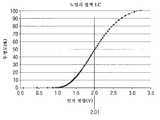
도 6은 액정 표시 셀의 양단에 인가되는 전압에 대하여 퍼센트로서 투과도를 측정하는 액정 표시 셀에 대한 전형적인 응답 프로파일을 도시한다. 응답은 포지티브 및 네거티브 인가된 전압에 대하여 일반적으로 대칭이라는 것이 이해될 것이다.6 shows a typical response profile for a liquid crystal display cell measuring its transmittance as a percentage of the voltage applied across the liquid crystal display cell. It will be appreciated that the response is generally symmetrical with respect to the positive and negative applied voltages.
도 6에 도시된 바와 같은 응답을 갖는 액정 표시 셀을 사용하고 그 액정 표시 셀이 저전력 모드를 위해 제안된 포화 상태에 있는 것을 사용하여, 액정 표시 셀 양단에 (포지티브나 네거티브인) 2.7 볼트를 인가하면 투과도가 제로로 효과적으로 감소할 것이다. 한편, 액정 표시 셀 양단에 제로 볼트를 인가하면, 액정 표시 셀은 대략 100 퍼센트 투과도를 제공한다.2.7 volts (positive or negative) are applied across the liquid crystal display cell, using a liquid crystal display cell having a response as shown in FIG. 6 and using that liquid crystal display cell in the saturation state proposed for the low power mode. The permeability will effectively decrease to zero. On the other hand, if zero volts are applied across the liquid crystal display cell, the liquid crystal display cell provides approximately 100 percent transmittance.
액정 표시 셀에 2.7 볼트가 인가되고 누설 전류가 있으면, 액정 표시 셀 양단의 전압은 감소할 것이다. 도 6에 도시된 특성으로부터, 전압은 투과도가 1 퍼센트만큼 증가하기 전에 0.8 볼트만큼 떨어질 수 있다는 것이 이해될 것이다. 한편, 액정 표시 셀에 초기에 제로 볼트가 제공되고 누설 전류가 있는 경우, 단지 0.25 볼트가 증가하게 되면 대략 1 퍼센트만큼 투과도가 감소하게 될 것이다.If 2.7 volts is applied to the liquid crystal display cell and there is a leakage current, the voltage across the liquid crystal display cell will decrease. From the characteristics shown in FIG. 6, it will be understood that the voltage may drop by 0.8 volts before the transmittance increases by 1 percent. On the other hand, if the liquid crystal display cell is initially provided with zero volts and there is a leakage current, the increase in only 0.25 volts will reduce the transmittance by approximately 1 percent.
한편에 전압 및 비투과도(non-transmittance)를 적용하는 것과 다른 편에 전압 및 투과도를 적용하지 않는 것 간의 비대칭을 고려하면, 액정 표시 셀의 응답의 제로 볼트/투과도 측이 누설 전류에 더 민감하다. 이것은 액정 표시 장치의 구동을 제어할 때 고려될 수 있다.Considering the asymmetry between applying voltage and non-transmittance on the one hand and not applying voltage and transmittance on the other hand, the zero volt / transmittance side of the response of the liquid crystal display cell is more sensitive to leakage current. . This may be considered when controlling the driving of the liquid crystal display.
이제 우선 프레임의 모든 수평 라인이 동일한 (포지티브 또는 네거티브) 전위로 구동되고 그 전위가 연속 프레임에 대하여 역전되는 프레임 반전 방법을 고려한다.Now consider first the frame reversal method in which all horizontal lines of the frame are driven to the same (positive or negative) potential and that potential is reversed with respect to the continuous frame.
특정의 개별 수직 신호 라인(28) 상의 액정 표시 셀(22)이 무작위 투과도 선택으로 구동된다고 가정하면, 액정 표시 장치를 구동하는 (또는 적어도 수직 열의 모든 액정 표시 셀(22)이 동일한 전위로 구동되는) 프레임 반전 방법에 대하여, 신호 라인을 사용하여 그 신호 라인이 접속된 액정 표시 셀(22)(환언하면, 다른 수직 열이 기입되는 동안) 그 신호 라인은, 누설 전류에 대하여, 그 신호 라인이 접속된 모든 액정 표시 셀(22)에 평균적으로 최소한의 해를 유발하는 전위로 되는 것이 바람직하다. 열에 있는 액정 표시 셀의 절반은 제로 볼트이고 그 열에 있는 액정 표시 셀의 절반은 최대 볼트라고 가정하면, 제로와 최대 볼트의 중간은 아니지만, 포화된 셀 상태 모두에 대한 누설 전류와 관련하여 동일한 효과를 갖는 도 6에 도시된 바와 같이 적절한 중간 전압(Vmid)을 계산하는 것이 가능하다.Assuming that the liquid crystal display cells 22 on a particular individual vertical signal line 28 are driven with random transmittance selection, the liquid crystal display device (or at least all liquid crystal display cells 22 in the vertical column are driven to the same potential). ) With respect to the frame inversion method, the liquid crystal display cell 22 (in other words, while another vertical column is written) to which the signal line is connected using the signal line is connected to the signal line with respect to the leakage current. It is preferable to become an electric potential which causes a minimum solution on the average of all connected liquid crystal display cells 22. Assuming that half of the liquid crystal display cells in a column are zero volts and half of the liquid crystal display cells in that column are maximal volts, they are not halfway between zero and maximum volts, but have the same effect with respect to leakage currents for both saturated cell states. It is possible to calculate the appropriate intermediate voltage Vmid as shown in FIG.
도 7은 적절한 중간 전압(Vmid)과 함께 제로 인가 전압에 대하여 제로 투명도를 갖는 액정 표시 셀의 응답을 도시한다. 도 6 및 도 7에 도시된 Vmid의 특정 값은 50% 투명도를 제공한다.7 shows the response of a liquid crystal display cell having zero transparency to zero applied voltage with an appropriate intermediate voltage Vmid. Certain values of Vmid shown in FIGS. 6 and 7 provide 50% transparency.
일 실시예에서, 신호 라인은 중간점에 있고 일반적으로 완전 투과 셀을 소정의 퍼센트(예를 들면, 1 퍼센트)만큼 투과도를 줄임과 동시에 비투과 셀은 동일한 투과도 퍼센트에 도달하도록 하는 전위에 놓일 수 있다. 이 방식에서, 액정 표시 장치가 허용불가하게 희미해지는데 걸리는 전체 시간은 최대화될 것이고 리프레시 레이트는 최대로 감소될 수 있다.In one embodiment, the signal line is at the midpoint and can generally be placed at a potential such that the non-transmissive cell reaches the same transmittance percentage while reducing the transmittance generally by a predetermined percentage (eg, 1 percent). . In this manner, the total time taken for the liquid crystal display to be unacceptably blurred will be maximized and the refresh rate can be reduced to the maximum.
전형적으로 투과도에 있어서 1 퍼센트의 변경이 사용자가 수용가능하게 시청하기 위한 적절한 최대값이 될 것이라는 것을 발견하였다.Typically it was found that a 1 percent change in permeability would be a reasonable maximum for the user to view acceptable.
전체의 프레임을 기입하면, 신호 라인은 바람직하게 적절한 Vmid에서 유지되고 Vcom은 그 다음 프레임까지 일정하게 된다. 픽셀의 프레임이 Vcom에 대하여 포지티브 전위로 구동되는 경우, Vmid는 Vcom에 대하여 포지티브이고, 픽셀의 프레임이 Vcom에 대하여 네거티브 전위로 구동되는 경우, Vmid는 Vcom에 대하여 네거티브라는 것이 이해될 것이다.Once the entire frame is written, the signal line is preferably held at the appropriate Vmid and Vcom remains constant until the next frame. It will be understood that if the frame of the pixel is driven at a positive potential with respect to Vcom, Vmid is positive with respect to Vcom and if the frame of the pixel is driven with a negative potential with respect to Vcom, then Vmid is negative with respect to Vcom.
도 5를 참조하여 전술한 바와 같은 1H 라인 반전 방법에 대하여, 각각의 신호 라인(28)은 물론, 하나의 수평 라인에서 그 다음 수평 라인으로 위아래로 움직이는 COM 라인에 대하여 전위가 포지티브로 또는 네거티브로 인가되는 액정 표시 셀(22)의 수직 어레이에 접속된다. 따라서, 하나의 수평 라인의 액정 표시 셀(22)이 그 양단에 제로 볼트의 전위를 갖거나 COM 라인에 대하여 최대의 포지티브 볼트(예를 들면, +2.7 볼트)의 전위를 가질 동안, 그 다음 수평 라인의 액정 표시 셀(22)은 제로 볼트 또는 COM 라인에 대하여 최대의 네거티브 전압(예를 들면, -2.7 볼트)의 전위를 가질 것이다.For the 1H line inversion method as described above with reference to FIG. 5, the potential is positive or negative for each signal line 28 as well as for the COM line moving up and down from one horizontal line to the next horizontal line. It is connected to a vertical array of liquid crystal display cells 22 that are applied. Thus, while the liquid crystal display cell 22 of one horizontal line has a potential of zero volts across it or a potential of maximum positive volts (eg, +2.7 volts) relative to the COM line, the next horizontal The liquid crystal display cell 22 of the line will have a potential of a maximum negative voltage (eg -2.7 volts) with respect to zero volts or a COM line.
따라서, 전술한 바와 같은 1H 반전 방법에 대하여, 개별 액정 표시 셀(22)에 원하는 신호를 기입하기 위해 신호 라인을 사용할 때 그 신호 라인이 COM 라인의 전위에, 평균적으로, 있는 것이 최상이다.Therefore, for the 1H inversion method as described above, when using a signal line to write a desired signal to the individual liquid crystal display cell 22, it is best that the signal line is, on average, at the potential of the COM line.
Vcom이 DC 레벨로 유지되는 액정 표시 장치를 위한 구동 방법을 사용하는 것도 공지되어 있다. 이것은 숙련된 독자에게 잘 이해될 것이지만, 도 8을 참조하여 간단히 설명한다.It is also known to use a driving method for the liquid crystal display device in which Vcom is maintained at the DC level. This will be well understood by the skilled reader, but will be briefly described with reference to FIG.
트레이스(b)로 도시된 바와 같이, Vcom은, 예를 들면, 1 볼트로 일정하게 유지된다.As shown by trace (b), Vcom is kept constant, for example, at 1 volt.
신호 라인은 트레이스(a)에 도시되어 있고 게이트 라인은 트레이스(c)에 도시되어 있다. 신호 라인이, 예를 들면, 2 볼트에 있는 동안, 게이트 펄스는 그 신호 라인을, 트레이스(e)에 도시된 바와 같이, 그 셀(Vcom측에 반대)의 전압(Vx)이 2 볼트의 신호 레벨로 상승하도록 특정 액정 표시 셀에 접속한다.The signal line is shown in trace (a) and the gate line is shown in trace (c). While the signal line is at, for example, 2 volts, the gate pulse causes the signal line to appear at trace e, with the voltage Vx of the cell (as opposed to the Vcom side) being a signal of 2 volts. It connects to a specific liquid crystal display cell so that it may raise to a level.
DC 구동 방법에 따르면, CS 전압이 Vcom 전압 뒤에 오지 않는다. 트레이스(d)에 도시된 바와 같이, 게이트 전압이 픽셀 트랜지스터를 인에이블하여 신호 전압을 액정 셀에 인가한 후, CS 전압은 0볼트에서 2볼트로 변경된다. CS 커패시터와 액정 셀의 비교 용량에 의존하여, 액정 셀 상의 전압(Vx)은 적절히 상승할 것이다. 도시된 예에서, 액정 셀 상의 전압(Vx)이 3 볼트까지 상승하도록 50%의 커플링 효과가 있다.According to the DC driving method, the CS voltage does not follow the Vcom voltage. As shown in trace d, after the gate voltage enables the pixel transistor to apply a signal voltage to the liquid crystal cell, the CS voltage is changed from 0 volts to 2 volts. Depending on the comparative capacitance of the CS capacitor and the liquid crystal cell, the voltage Vx on the liquid crystal cell will rise appropriately. In the example shown, there is a coupling effect of 50% so that the voltage Vx on the liquid crystal cell rises to 3 volts.
다음 프레임에서, 액정 셀에 반대 극성을 인가하기 위해, 게이트는 트랜지스 터를 인에이블하여 0 볼트의 신호 전압을 Vx에 인가한다. 그러나, CS가 0 볼트로 리턴되는 경우, 커플링 효과는 액정 셀 양단의 전압이 -1 볼트로 더 떨어지게 한다.In the next frame, to apply the opposite polarity to the liquid crystal cell, the gate enables the transistor to apply a signal voltage of 0 volts to Vx. However, when CS is returned to 0 volts, the coupling effect causes the voltage across the liquid crystal cell to fall further to -1 volts.
따라서, 프레임으로부터 프레임으로, Vcom(+1 볼트)에 대하여 액정 셀 양단의 전압은 +2 볼트에서 -2 볼트까지 가변할 것이라는 것이 이해될 것이다.Thus, it will be appreciated that from frame to frame, the voltage across the liquid crystal cell for Vcom (+1 volt) will vary from +2 volts to -2 volts.
각각의 수평 라인을 개별적으로 제어하기 위해, 각각의 수평 라인에 대한 CS 라인이 개별적으로 제어된다는 것이 이해될 것이다.It will be appreciated that in order to control each horizontal line individually, the CS line for each horizontal line is controlled individually.
1H 반전 구동 방법에 대하여, 일단 전체 프레임이 기입되면, +1 볼트 및 +3 볼트의 포지티브 극성 픽셀들, 및 +1 볼트 및 -1 볼트의 네거티브 극성 픽셀들의 혼합이 될 것이다. 이에 따라, 그 다음 프레임이 기입될 때까지, 신호 라인은 누설 전류를 최소화하기 위해 Vcom 전압, 이 경우 +1 볼트로 유지되어야 하는 것이 제안된다.For the 1H inversion drive method, once the entire frame is written, there will be a mix of positive polarity pixels of +1 volts and +3 volts, and negative polarity pixels of +1 volts and -1 volts. Accordingly, it is proposed that the signal line should be maintained at the Vcom voltage, in this case +1 volts, to minimize leakage current until the next frame is written.
1F 반전 방법에 대하여, 한 프레임의 기입이 끝날 때, 포지티브 극성 프레임에 대하여, 액정 셀은 1 볼트 및 3 볼트 간의 혼합이 되는 반면, 네거티브 극성 프레임에 대하여, 액정 셀은 1 볼트 및 -1 볼트의 혼합이 될 것이다.For the 1F inversion method, when writing of one frame is finished, for a positive polarity frame, the liquid crystal cell is mixed between 1 volt and 3 volts, whereas for a negative polarity frame, the liquid crystal cell is 1 volt and -1 volts. Will be mixed.
또 다른 방법을 고려하면, 포지티브 극성 프레임에 대하여, Vcom과 관련하여, 액정 셀은 0 볼트 및 2 볼트의 혼합이 될 것이다. 한편, 네거티브 극성 프레임에 대하여, Vcom과 관련하여, 액정 셀은 0 볼트 및 -2 볼트의 혼합이 될 것이다. 따라서, 포지티브 극성 프레임에 대하여, 신호 라인 레벨을 AC 구동 방법용으로 전술한 중간 전압으로 설정하고 그 중간 전압은 Vcom 이상으로 설정하는 것을 제안한 다. 한편, 네거티브 극성 프레임에 대하여, 신호 라인 레벨은 Vcom 전압에 대하여 네거티브 극성을 갖는 중간 전압 레벨로 설정될 것이다.Considering another method, for a positive polarity frame, with respect to Vcom, the liquid crystal cell will be a mixture of 0 volts and 2 volts. On the other hand, for the negative polarity frame, with respect to Vcom, the liquid crystal cell will be a mixture of 0 volts and -2 volts. Therefore, for a positive polarity frame, it is proposed to set the signal line level to the above-mentioned intermediate voltage for the AC driving method and to set the intermediate voltage above Vcom. On the other hand, for a negative polarity frame, the signal line level will be set to an intermediate voltage level with negative polarity for the Vcom voltage.
물론, 구동 회로가 표시되는 실제 이미지 및 특정 신호 라인(28)의 개별 액정 표시 셀(22)에 제공되는 실제 전위를 고려하는 것도 가능하다. 특정 신호 라인(28)의 액정 표시 셀(22) 상에 제공된 실제 전위를 기초로 하면, 개별 액정 표시 셀(22)에 기입하는 사이 그 신호 라인(28) 상에 제공되는 전위는 누설 전류를 최소화하고 후속의 리프레시 프레임들 간의 최대 시간을 가능하게 하도록 최적값으로 제어된다.Of course, it is also possible to consider the actual image on which the drive circuit is displayed and the actual potential provided to the individual liquid crystal display cells 22 of the particular signal line 28. Based on the actual potential provided on the liquid crystal display cell 22 of a particular signal line 28, the potential provided on that signal line 28 between writing to the individual liquid crystal display cell 22 minimizes leakage current. And the optimum value to enable the maximum time between subsequent refresh frames.
전수한 기술에 의해, 50-60 Hz의 노말 모드 리프레시 레이트는 저전력 모드 동안 10 Hz 이하 또는 5 Hz 이하로 감소될 수 있다. 사실상, 저전력 모드에 대하여 초당 10 내지 1회의 리프레시 레이트를 제공하는 것이 제안된다.By means of conventional techniques, the normal mode refresh rate of 50-60 Hz can be reduced to below 10 Hz or below 5 Hz during the low power mode. In fact, it is proposed to provide 10 to 1 refresh rate per second for the low power mode.
전술한 바와 같은 구성에 의해, 전형적인 3 mW의 전력 소모가 1 mW이하로 감소될 수 있다는 것이 관찰된다.By the configuration as described above, it is observed that a typical 3 mW power consumption can be reduced to less than 1 mW.
도 1은 본 발명이 구체화될 수 있는 이동 전화를 도시한 도면.1 illustrates a mobile phone in which the present invention may be embodied.
도 2는 본 발명이 구체화될 수 있는 카메라를 도시한 도면.2 illustrates a camera in which the present invention may be embodied.
도 3은 본 발명이 구체화될 수 있는 액정 표시 모듈을 도시한 도면.3 illustrates a liquid crystal display module in which the present invention can be embodied.
도 4는 액정 표시 장치의 픽셀의 세개의 픽셀 유닛들을 개략적으로 도시한 도면.4 schematically illustrates three pixel units of a pixel of a liquid crystal display;
도 5는 도 4의 픽셀 유닛들을 구동하기 위한 신호의 타이밍을 도시한 도면.FIG. 5 illustrates timing of a signal for driving the pixel units of FIG. 4. FIG.
도 6은 전형적인 액정 표시 셀의 전송 응답을 도시한 도면.6 shows a transmission response of a typical liquid crystal display cell.
도 7은 또 다른 전형적인 액정 표시 셀의 전송 응답을 도시한 도면.7 illustrates a transmission response of another exemplary liquid crystal display cell.
도 8은 액정 표시 셀의 DC 구동을 개략적으로 도시한 도면.8 is a diagram schematically showing DC driving of a liquid crystal display cell.
Claims (23)
Translated fromKoreanApplications Claiming Priority (2)
| Application Number | Priority Date | Filing Date | Title |
|---|---|---|---|
| GB0809584.6 | 2008-05-27 | ||
| GB0809584.6AGB2460409B (en) | 2008-05-27 | 2008-05-27 | Driving circuit for a liquid crystal display |
Publications (1)
| Publication Number | Publication Date |
|---|---|
| KR20090123804Atrue KR20090123804A (en) | 2009-12-02 |
Family
ID=39616136
Family Applications (1)
| Application Number | Title | Priority Date | Filing Date |
|---|---|---|---|
| KR1020090046016AWithdrawnKR20090123804A (en) | 2008-05-27 | 2009-05-26 | Driving circuit for liquid crystal display |
Country Status (6)
| Country | Link |
|---|---|
| US (1) | US20090295786A1 (en) |
| JP (1) | JP2009288789A (en) |
| KR (1) | KR20090123804A (en) |
| CN (1) | CN101593498A (en) |
| GB (1) | GB2460409B (en) |
| TW (1) | TW201007685A (en) |
Cited By (3)
| Publication number | Priority date | Publication date | Assignee | Title |
|---|---|---|---|---|
| KR20170067674A (en)* | 2015-11-12 | 2017-06-16 | 시아오미 아이엔씨. | Liquid crystal display method and device |
| KR20170067675A (en)* | 2015-11-12 | 2017-06-16 | 시아오미 아이엔씨. | Liquid crystal display method and device |
| US10176740B2 (en) | 2015-03-19 | 2019-01-08 | Samsung Display Co., Ltd. | Display device |
Families Citing this family (16)
| Publication number | Priority date | Publication date | Assignee | Title |
|---|---|---|---|---|
| GB2458957B (en)* | 2008-04-04 | 2010-11-24 | Sony Corp | Liquid crystal display module |
| GB2460090A (en) | 2008-05-16 | 2009-11-18 | Sony Corp | Ambient light detection device |
| US8358260B2 (en)* | 2009-04-06 | 2013-01-22 | Intel Corporation | Method and apparatus for adaptive black frame insertion |
| CN105353551A (en)* | 2009-12-28 | 2016-02-24 | 株式会社半导体能源研究所 | Liquid crystal display device and electronic device |
| US20120327137A1 (en)* | 2010-03-19 | 2012-12-27 | Sharp Kabushiki Kaisha | Display device and display driving method |
| US8842111B2 (en)* | 2010-09-20 | 2014-09-23 | Intel Corporation | Techniques for selectively changing display refresh rate |
| US8669970B2 (en) | 2011-01-27 | 2014-03-11 | Apple Inc. | Master synchronization for multiple displays |
| WO2014045749A1 (en) | 2012-09-21 | 2014-03-27 | シャープ株式会社 | Display control system, processor, controller, and display control method |
| KR101773269B1 (en) | 2012-11-20 | 2017-08-31 | 샤프 가부시키가이샤 | Control device, display device, and display device control method |
| US10013940B2 (en)* | 2012-12-31 | 2018-07-03 | Nvidia Corporation | Method and apparatus to reduce panel power through horizontal interlaced addressing |
| US9823728B2 (en) | 2013-09-04 | 2017-11-21 | Nvidia Corporation | Method and system for reduced rate touch scanning on an electronic device |
| US9881592B2 (en) | 2013-10-08 | 2018-01-30 | Nvidia Corporation | Hardware overlay assignment |
| US10332460B2 (en)* | 2016-07-04 | 2019-06-25 | Innolux Corporation | Display and driving method thereof |
| KR102699276B1 (en)* | 2018-08-08 | 2024-08-28 | 삼성디스플레이 주식회사 | Display device and method of driving the same |
| KR102545078B1 (en)* | 2018-10-01 | 2023-06-19 | 삼성전자주식회사 | Display apparatus, method for controlling thereof and system |
| CN117831438A (en)* | 2022-09-28 | 2024-04-05 | 群创光电股份有限公司 | Method for driving electronic device |
Family Cites Families (29)
| Publication number | Priority date | Publication date | Assignee | Title |
|---|---|---|---|---|
| DE69220173T2 (en)* | 1991-10-07 | 1997-09-18 | Fujitsu Ltd | Method for controlling a surface stabilized ferroelectric liquid crystal display element to increase the gray level number |
| DE69411957T2 (en)* | 1993-01-11 | 1999-01-14 | Canon K.K., Tokio/Tokyo | Display line distribution system |
| US5757365A (en)* | 1995-06-07 | 1998-05-26 | Seiko Epson Corporation | Power down mode for computer system |
| JP3234131B2 (en)* | 1995-06-23 | 2001-12-04 | 株式会社東芝 | Liquid crystal display |
| KR100653751B1 (en)* | 1998-10-27 | 2006-12-05 | 샤프 가부시키가이샤 | Driving method of display panel, driving circuit of display panel, and liquid crystal display device |
| US6489952B1 (en)* | 1998-11-17 | 2002-12-03 | Semiconductor Energy Laboratory Co., Ltd. | Active matrix type semiconductor display device |
| US6469684B1 (en)* | 1999-09-13 | 2002-10-22 | Hewlett-Packard Company | Cole sequence inversion circuitry for active matrix device |
| JP3723747B2 (en)* | 2000-06-16 | 2005-12-07 | 松下電器産業株式会社 | Display device and driving method thereof |
| JP5019668B2 (en)* | 2000-09-18 | 2012-09-05 | 三洋電機株式会社 | Display device and control method thereof |
| JP3842030B2 (en)* | 2000-10-06 | 2006-11-08 | シャープ株式会社 | Active matrix display device and driving method thereof |
| TW493158B (en)* | 2001-05-29 | 2002-07-01 | Hannstar Display Corp | Transistor array circuit for liquid crystal display |
| JP4111785B2 (en)* | 2001-09-18 | 2008-07-02 | シャープ株式会社 | Liquid crystal display |
| JP3917845B2 (en)* | 2001-11-16 | 2007-05-23 | シャープ株式会社 | Liquid crystal display |
| JP4190862B2 (en)* | 2001-12-18 | 2008-12-03 | シャープ株式会社 | Display device and driving method thereof |
| KR100910561B1 (en)* | 2002-12-31 | 2009-08-03 | 삼성전자주식회사 | Liquid crystal display |
| TW578124B (en)* | 2003-01-03 | 2004-03-01 | Au Optronics Corp | Method and driver for reducing power consumption of an LCD panel in a standby mode |
| KR100997977B1 (en)* | 2004-01-12 | 2010-12-02 | 삼성전자주식회사 | Optical sensor and display device using same |
| JP2005227627A (en)* | 2004-02-13 | 2005-08-25 | Sharp Corp | Display device drive device, display device, and display device drive method |
| JP2005300948A (en)* | 2004-04-13 | 2005-10-27 | Hitachi Displays Ltd | Display device and driving method thereof |
| JP2006039337A (en)* | 2004-07-29 | 2006-02-09 | Nec Electronics Corp | Liquid crystal display and driving circuit thereof |
| US7659876B2 (en)* | 2004-07-29 | 2010-02-09 | Koninklijke Philips Electronics N.V. | Driving a display with a polarity inversion pattern |
| JP2007065454A (en)* | 2005-09-01 | 2007-03-15 | Nec Electronics Corp | Liquid crystal display and its driving method |
| JP4786996B2 (en)* | 2005-10-20 | 2011-10-05 | 株式会社 日立ディスプレイズ | Display device |
| US7605794B2 (en)* | 2005-12-22 | 2009-10-20 | Nokia Corporation | Adjusting the refresh rate of a display |
| KR101177579B1 (en)* | 2005-12-30 | 2012-08-27 | 엘지디스플레이 주식회사 | Liquid crystal display device and method for driving the same |
| US8179388B2 (en)* | 2006-12-15 | 2012-05-15 | Nvidia Corporation | System, method and computer program product for adjusting a refresh rate of a display for power savings |
| US7903107B2 (en)* | 2007-06-18 | 2011-03-08 | Sony Ericsson Mobile Communications Ab | Adaptive refresh rate features |
| KR101224459B1 (en)* | 2007-06-28 | 2013-01-22 | 엘지디스플레이 주식회사 | Liquid Crystal Display |
| US7761685B2 (en)* | 2007-11-20 | 2010-07-20 | Seiko Epson Corporation | Compressing and decompressing image data without introducing artifacts |
- 2008
- 2008-05-27GBGB0809584.6Apatent/GB2460409B/ennot_activeExpired - Fee Related
- 2009
- 2009-04-20TWTW098113026Apatent/TW201007685A/enunknown
- 2009-05-26KRKR1020090046016Apatent/KR20090123804A/ennot_activeWithdrawn
- 2009-05-26CNCNA2009101418112Apatent/CN101593498A/enactivePending
- 2009-05-27USUS12/473,022patent/US20090295786A1/ennot_activeAbandoned
- 2009-05-27JPJP2009127601Apatent/JP2009288789A/enactivePending
Cited By (3)
| Publication number | Priority date | Publication date | Assignee | Title |
|---|---|---|---|---|
| US10176740B2 (en) | 2015-03-19 | 2019-01-08 | Samsung Display Co., Ltd. | Display device |
| KR20170067674A (en)* | 2015-11-12 | 2017-06-16 | 시아오미 아이엔씨. | Liquid crystal display method and device |
| KR20170067675A (en)* | 2015-11-12 | 2017-06-16 | 시아오미 아이엔씨. | Liquid crystal display method and device |
Also Published As
| Publication number | Publication date |
|---|---|
| US20090295786A1 (en) | 2009-12-03 |
| CN101593498A (en) | 2009-12-02 |
| GB2460409B (en) | 2012-04-04 |
| TW201007685A (en) | 2010-02-16 |
| GB2460409A (en) | 2009-12-02 |
| JP2009288789A (en) | 2009-12-10 |
| GB0809584D0 (en) | 2008-07-02 |
Similar Documents
| Publication | Publication Date | Title |
|---|---|---|
| KR20090123804A (en) | Driving circuit for liquid crystal display | |
| KR100553326B1 (en) | Display apparatus and driving method of same | |
| KR100393150B1 (en) | Liquid crystal display device | |
| CN107665692B (en) | Pixel driving circuit and pixel driving method of liquid crystal display | |
| US20060119557A1 (en) | System and method for driving an LCD | |
| US20090251445A1 (en) | Driving circuit for a liquid crystal display | |
| US20020003522A1 (en) | Display method for liquid crystal display device | |
| US20010033278A1 (en) | Display device driving circuit, driving method of display device, and image display device | |
| US20100231814A1 (en) | Liquid crystal display device and its driving method | |
| US20120327137A1 (en) | Display device and display driving method | |
| US8232932B2 (en) | Display device | |
| KR100517395B1 (en) | Display device, electronic device and driving method | |
| US8456398B2 (en) | Liquid crystal display module | |
| KR20130105330A (en) | Liquid crystal display device, driving method of liquid crystal display device and electronic apparatus | |
| US8704809B2 (en) | Pixel circuit and display device | |
| CN111009224A (en) | Display panel driving method and display device | |
| JP2009205045A (en) | Electrooptical device, driving method, and electronic equipment | |
| US20080158125A1 (en) | Liquid crystal display device | |
| KR20130057704A (en) | Display device and driving method thereof | |
| US8179392B2 (en) | Pre-charge system for on glass LCD driving circuit | |
| CN118335034B (en) | Pixel driving circuit, display panel and driving method thereof | |
| US20040263453A1 (en) | Liquid crystal display device and method of fabricating the same | |
| JP2003280601A (en) | Liquid crystal display | |
| US7812911B2 (en) | Liquid crystal display | |
| JPH0338617A (en) | liquid crystal display device |
Legal Events
| Date | Code | Title | Description |
|---|---|---|---|
| PA0109 | Patent application | Patent event code:PA01091R01D Comment text:Patent Application Patent event date:20090526 | |
| PG1501 | Laying open of application | ||
| PC1203 | Withdrawal of no request for examination | ||
| WITN | Application deemed withdrawn, e.g. because no request for examination was filed or no examination fee was paid |