KR20090123259A - Display tag, display tag system including the same, and tag information recording method - Google Patents
Display tag, display tag system including the same, and tag information recording methodDownload PDFInfo
- Publication number
- KR20090123259A KR20090123259AKR1020080049236AKR20080049236AKR20090123259AKR 20090123259 AKR20090123259 AKR 20090123259AKR 1020080049236 AKR1020080049236 AKR 1020080049236AKR 20080049236 AKR20080049236 AKR 20080049236AKR 20090123259 AKR20090123259 AKR 20090123259A
- Authority
- KR
- South Korea
- Prior art keywords
- tag
- display
- image
- unit
- display unit
- Prior art date
- Legal status (The legal status is an assumption and is not a legal conclusion. Google has not performed a legal analysis and makes no representation as to the accuracy of the status listed.)
- Abandoned
Links
Images


Classifications
- G—PHYSICS
- G06—COMPUTING OR CALCULATING; COUNTING
- G06F—ELECTRIC DIGITAL DATA PROCESSING
- G06F3/00—Input arrangements for transferring data to be processed into a form capable of being handled by the computer; Output arrangements for transferring data from processing unit to output unit, e.g. interface arrangements
- G06F3/01—Input arrangements or combined input and output arrangements for interaction between user and computer
- G06F3/048—Interaction techniques based on graphical user interfaces [GUI]
- G06F3/0481—Interaction techniques based on graphical user interfaces [GUI] based on specific properties of the displayed interaction object or a metaphor-based environment, e.g. interaction with desktop elements like windows or icons, or assisted by a cursor's changing behaviour or appearance
- G06F3/0482—Interaction with lists of selectable items, e.g. menus
- H—ELECTRICITY
- H04—ELECTRIC COMMUNICATION TECHNIQUE
- H04N—PICTORIAL COMMUNICATION, e.g. TELEVISION
- H04N5/00—Details of television systems
- H04N5/44—Receiver circuitry for the reception of television signals according to analogue transmission standards
- G—PHYSICS
- G06—COMPUTING OR CALCULATING; COUNTING
- G06F—ELECTRIC DIGITAL DATA PROCESSING
- G06F3/00—Input arrangements for transferring data to be processed into a form capable of being handled by the computer; Output arrangements for transferring data from processing unit to output unit, e.g. interface arrangements
- G06F3/01—Input arrangements or combined input and output arrangements for interaction between user and computer
- G06F3/048—Interaction techniques based on graphical user interfaces [GUI]
- G06F3/0484—Interaction techniques based on graphical user interfaces [GUI] for the control of specific functions or operations, e.g. selecting or manipulating an object, an image or a displayed text element, setting a parameter value or selecting a range
- G—PHYSICS
- G06—COMPUTING OR CALCULATING; COUNTING
- G06K—GRAPHICAL DATA READING; PRESENTATION OF DATA; RECORD CARRIERS; HANDLING RECORD CARRIERS
- G06K19/00—Record carriers for use with machines and with at least a part designed to carry digital markings
- G06K19/06—Record carriers for use with machines and with at least a part designed to carry digital markings characterised by the kind of the digital marking, e.g. shape, nature, code
- G06K19/067—Record carriers with conductive marks, printed circuits or semiconductor circuit elements, e.g. credit or identity cards also with resonating or responding marks without active components
- G06K19/07—Record carriers with conductive marks, printed circuits or semiconductor circuit elements, e.g. credit or identity cards also with resonating or responding marks without active components with integrated circuit chips
- G06K19/0701—Record carriers with conductive marks, printed circuits or semiconductor circuit elements, e.g. credit or identity cards also with resonating or responding marks without active components with integrated circuit chips at least one of the integrated circuit chips comprising an arrangement for power management
- G06K19/0707—Record carriers with conductive marks, printed circuits or semiconductor circuit elements, e.g. credit or identity cards also with resonating or responding marks without active components with integrated circuit chips at least one of the integrated circuit chips comprising an arrangement for power management the arrangement being capable of collecting energy from external energy sources, e.g. thermocouples, vibration, electromagnetic radiation
- G—PHYSICS
- G06—COMPUTING OR CALCULATING; COUNTING
- G06K—GRAPHICAL DATA READING; PRESENTATION OF DATA; RECORD CARRIERS; HANDLING RECORD CARRIERS
- G06K19/00—Record carriers for use with machines and with at least a part designed to carry digital markings
- G06K19/06—Record carriers for use with machines and with at least a part designed to carry digital markings characterised by the kind of the digital marking, e.g. shape, nature, code
- G06K19/067—Record carriers with conductive marks, printed circuits or semiconductor circuit elements, e.g. credit or identity cards also with resonating or responding marks without active components
- G06K19/07—Record carriers with conductive marks, printed circuits or semiconductor circuit elements, e.g. credit or identity cards also with resonating or responding marks without active components with integrated circuit chips
- G06K19/0723—Record carriers with conductive marks, printed circuits or semiconductor circuit elements, e.g. credit or identity cards also with resonating or responding marks without active components with integrated circuit chips the record carrier comprising an arrangement for non-contact communication, e.g. wireless communication circuits on transponder cards, non-contact smart cards or RFIDs
- G—PHYSICS
- G06—COMPUTING OR CALCULATING; COUNTING
- G06K—GRAPHICAL DATA READING; PRESENTATION OF DATA; RECORD CARRIERS; HANDLING RECORD CARRIERS
- G06K19/00—Record carriers for use with machines and with at least a part designed to carry digital markings
- G06K19/06—Record carriers for use with machines and with at least a part designed to carry digital markings characterised by the kind of the digital marking, e.g. shape, nature, code
- G06K19/067—Record carriers with conductive marks, printed circuits or semiconductor circuit elements, e.g. credit or identity cards also with resonating or responding marks without active components
- G06K19/07—Record carriers with conductive marks, printed circuits or semiconductor circuit elements, e.g. credit or identity cards also with resonating or responding marks without active components with integrated circuit chips
- G06K19/077—Constructional details, e.g. mounting of circuits in the carrier
- G06K19/07701—Constructional details, e.g. mounting of circuits in the carrier the record carrier comprising an interface suitable for human interaction
- G06K19/07703—Constructional details, e.g. mounting of circuits in the carrier the record carrier comprising an interface suitable for human interaction the interface being visual
- G—PHYSICS
- G06—COMPUTING OR CALCULATING; COUNTING
- G06K—GRAPHICAL DATA READING; PRESENTATION OF DATA; RECORD CARRIERS; HANDLING RECORD CARRIERS
- G06K7/00—Methods or arrangements for sensing record carriers, e.g. for reading patterns
- G06K7/10—Methods or arrangements for sensing record carriers, e.g. for reading patterns by electromagnetic radiation, e.g. optical sensing; by corpuscular radiation
- G06K7/10009—Methods or arrangements for sensing record carriers, e.g. for reading patterns by electromagnetic radiation, e.g. optical sensing; by corpuscular radiation sensing by radiation using wavelengths larger than 0.1 mm, e.g. radio-waves or microwaves
- G06K7/10316—Methods or arrangements for sensing record carriers, e.g. for reading patterns by electromagnetic radiation, e.g. optical sensing; by corpuscular radiation sensing by radiation using wavelengths larger than 0.1 mm, e.g. radio-waves or microwaves using at least one antenna particularly designed for interrogating the wireless record carriers
- G06K7/10346—Methods or arrangements for sensing record carriers, e.g. for reading patterns by electromagnetic radiation, e.g. optical sensing; by corpuscular radiation sensing by radiation using wavelengths larger than 0.1 mm, e.g. radio-waves or microwaves using at least one antenna particularly designed for interrogating the wireless record carriers the antenna being of the far field type, e.g. HF types or dipoles
Landscapes
- Engineering & Computer Science (AREA)
- Physics & Mathematics (AREA)
- Theoretical Computer Science (AREA)
- General Physics & Mathematics (AREA)
- Microelectronics & Electronic Packaging (AREA)
- Computer Hardware Design (AREA)
- General Engineering & Computer Science (AREA)
- Computer Networks & Wireless Communication (AREA)
- Electromagnetism (AREA)
- Toxicology (AREA)
- Health & Medical Sciences (AREA)
- Human Computer Interaction (AREA)
- Computer Vision & Pattern Recognition (AREA)
- Artificial Intelligence (AREA)
- General Health & Medical Sciences (AREA)
- Multimedia (AREA)
- Signal Processing (AREA)
- Controls And Circuits For Display Device (AREA)
- Control Of Indicators Other Than Cathode Ray Tubes (AREA)
Abstract
Description
Translated fromKorean본 발명은 디스플레이 태그 및 이를 포함하는 디스플레이 태그 시스템과 그 태그 정보 기록 방법에 관한 것으로서, 보다 상세하게는 외부의 디스플레이 화상을 캡쳐하여 디스플레이할 수 있는 디스플레이 태그 및 이를 포함하는 디스플레이 태그 시스템과 그 태그 정보 기록 방법에 관한 것이다.The present invention relates to a display tag, a display tag system including the same, and a method of recording tag information thereof, and more particularly, a display tag capable of capturing and displaying an external display image, and a display tag system including the same and tag information thereof. It relates to a recording method.
최근 통신 기술의 발전에 힘입어, 상품의 위치 추적, 재고 관리를 수행하거나, 사용자 확인을 수행하거나, 컨텐츠를 획득하는 등 무선 주파수를 이용한 기술이 산업 전반에 걸쳐 폭 넓게 이용되고 있다. 이러한 무선 주파수 기술을 구현하기 위한 무선 주파수 시스템은 태그(tag), 태그 리더(tag reader), 태그 라이터(tag writer) 등과 같은 구성 요소를 구비할 수 있다.Recently, with the development of communication technology, technology using radio frequency has been widely used throughout the industry such as location tracking, inventory management, user verification, and content acquisition. A radio frequency system for implementing such radio frequency technology may include components such as a tag, a tag reader, a tag writer, and the like.
이와 같은 무선 주파수 시스템에서, 태그는 내부 전원 없이 리더 또는 라이터의 전자기파 신호로부터 에너지를 공급받아 동작하는 수동형 태그(passive tag)와 자체적으로 전원을 구비하여 동작하는 능동형 태그(active tag)로 구분될 수 있 다. 또한, 실리콘 반도체 칩을 사용하는 칩 태그(chip tag)와 LC 소자, 플라스틱 또는 폴리머(polymer: 중합체) 소자로만 구성된 무칩 태그(chipless tag)로 구분될 수도 있다.In such a radio frequency system, a tag may be classified into a passive tag that operates by receiving energy from an electromagnetic signal of a reader or a writer without an internal power source, and an active tag that operates with its own power source. have. In addition, it may be divided into a chip tag using a silicon semiconductor chip and a chipless tag composed only of an LC device, a plastic or a polymer (polymer) device.
이러한, 종래의 무선 주파수 시스템에서는 태그와 태그 리더/태그 라이터 간에 RF(Radio Frequency)와 같은 전자기파를 이용하여 태그 정보를 송수신할 수 있었다. 이에 따라, 디스플레이 화면을 구비한 태그 리더를 통해 태그에 저장된 정보를 확인하는 방법 이외에는, 태그에 기록되어 있는 태그 정보의 내용을 구체적으로 확인하기 어려운 문제점이 있었다.In the conventional radio frequency system, tag information may be transmitted and received between an tag and a tag reader / tag writer using electromagnetic waves such as RF (Radio Frequency). Accordingly, there is a problem that it is difficult to specifically check the contents of the tag information recorded in the tag except for the method of confirming the information stored in the tag through the tag reader having the display screen.
본 발명은 상술한 문제점을 해결하기 위해 안출된 것으로서, 외부의 디스플레이 화상을 캡쳐하여 디스플레이할 수 있는 디스플레이 태그 및 이를 포함하는 디스플레이 태그 시스템과 그 태그 정보 기록 방법을 제공하는데 그 목적이 있다.SUMMARY OF THE INVENTION The present invention has been made to solve the above-described problem, and an object thereof is to provide a display tag capable of capturing and displaying an external display image, a display tag system including the same, and a method of recording the tag information.
본 발명의 일 실시 예에 따른 디스플레이 태그는, 외부 태그 기록 장치의 화면과 대향 배치되면, 상기 화면상에서 대향 배치된 부분에 표시된 화상을 캡쳐하는 센싱부, 및, 상기 캡쳐된 화상을 디스플레이하는 디스플레이부를 포함한다.The display tag according to an embodiment of the present disclosure may include a sensing unit configured to capture an image displayed on a portion of the external tag recording apparatus facing the screen of the external tag recording apparatus, and a display unit configured to display the captured image. Include.
여기서, 상기 디스플레이부는, 전자종이(E-PAPER)를 포함할 수 있다.The display unit may include electronic paper (E-PAPER).
이 경우, 상기 센싱부의 ON 또는 OFF 동작을 제어하기 위한 스위칭부를 더 포함할 수 있다.In this case, the sensing unit may further include a switching unit for controlling the ON or OFF operation.
또한, 열, 진동, 상기 외부 태그 기록 장치로부터 전달되는 광, 전자기파 중 적어도 하나에 의해 전원을 발생시켜 상기 센싱부 및 상기 디스플레이부를 동작시키는 전원 발생부를 더 포함할 수 있다.The apparatus may further include a power generator configured to generate power by at least one of heat, vibration, light transmitted from the external tag recording apparatus, and electromagnetic waves to operate the sensing unit and the display unit.
아울러, 상기 외부 태그 기록 장치에 의해 태그 정보가 기록되는 태그 정보 저장부를 더 포함할 수 있다.The apparatus may further include a tag information storage unit in which tag information is recorded by the external tag recording apparatus.
이때, 상기 센싱부는, 상기 디스플레이부의 크기에 대응되는 센싱 영역을 이루며, 상기 외부 디스플레이 장치의 화면상에 디스플레이되는 화상의 광을 각각 수신하여, 그 광의 세기에 따른 출력 신호를 출력하는 복수 개의 센서를 포함할 수 있다.In this case, the sensing unit forms a sensing area corresponding to the size of the display unit, and receives a plurality of sensors that respectively receive light of an image displayed on a screen of the external display device and output an output signal according to the intensity of the light. It may include.
또한, 상기 복수 개의 센서 각각으로부터 출력되는 출력 신호에 따라 상기 디스플레이부의 각 픽셀의 구동을 제어하는 구동회로부를 더 포함할 수 있으며, 상기 센싱부, 상기 구동회로부 및 상기 디스플레이부 각각은 층 형태로 순차적으로 배치될 수 있다.The display apparatus may further include a driving circuit unit that controls driving of each pixel of the display unit according to an output signal output from each of the plurality of sensors, wherein each of the sensing unit, the driving circuit unit, and the display unit is sequentially formed in a layer form. It can be arranged as.
한편, 본 발명의 일 실시 예에 따른 디스플레이 태그 시스템은, 제공 가능한 태그 정보에 대응되는 화상을 표시하는 태그 기록 장치, 및, 상기 태그 기록 장치의 화면상에서 태그 기록 영역과 대향 배치되면, 상기 태그 기록 영역에 표시된 화상을 캡쳐하는 디스플레이 태그를 포함한다.On the other hand, the display tag system according to an embodiment of the present invention, the tag recording device for displaying an image corresponding to the tag information that can be provided, and when the tag recording area is disposed opposite the tag recording area on the screen of the tag recording device, the tag recording It includes a display tag that captures the image displayed in the area.
여기서, 상기 태그 기록 장치는, 소정 화상이 태그 기록 영역에 표시된 상태에서 상기 디스플레이 태그가 상기 태그 기록 영역에 대향 배치되면, 상기 소정 화상에 대응되는 태그 정보를 상기 디스플레이 태그에 기록할 수 있다.Here, the tag recording apparatus may record tag information corresponding to the predetermined image to the display tag when the display tag is disposed opposite to the tag recording region while a predetermined image is displayed in the tag recording region.
한편, 본 발명의 일 실시 예에 따른 디스플레이 장치는, 디스플레이부, 및,외부 디스플레이 장치의 화면과 대향 배치되면, 상기 디스플레이부에 대응되는 부분에 표시된 화상을 캡쳐하여, 상기 디스플레이부로 제공하는 센싱부를 포함한다.On the other hand, the display device according to an embodiment of the present invention, the display unit, and, if disposed facing the screen of the external display device, the sensing unit for capturing the image displayed on the portion corresponding to the display unit, and provides the display unit Include.
여기서, 상기 디스플레이부는, 상기 캡쳐된 화상에 대응되는 화상을 디스플레이하며, 전원 오프시에도 디스플레이 상태를 유지하는 전자 종이를 포함할 수 있다.The display unit may include an electronic paper that displays an image corresponding to the captured image and maintains a display state even when the power is turned off.
한편 본 발명의 일 실시 예에 따른 디스플레이 태그 시스템의 태그 정보 기록 방법은, 태그 기록 장치에서 제공 가능한 태그 정보에 대응되는 적어도 하나의 화상을 표시하는 단계, 상기 적어도 하나의 화상 중 하나가 선택되면 선택된 화상을 화면상의 태그 기록 영역에 표시하는 단계, 및, 디스플레이부를 구비한 디스플레이 태그가 상기 태그 기록 영역에 대향 배치되면, 상기 디스플레이 태그가 상기 태그 기록 영역에 표시된 화상을 캡쳐하여 상기 디스플레이부에 표시하고, 상기 태그 기록 장치가 상기 선택된 화상에 대응되는 태그 정보를 상기 디스플레이 태그에 기록하는 단계를 포함한다.On the other hand, the tag information recording method of the display tag system according to an embodiment of the present invention, displaying at least one image corresponding to the tag information that can be provided by the tag recording device, if one of the at least one image is selected Displaying an image in a tag recording area on a screen; and when a display tag having a display unit is disposed opposite the tag recording area, the display tag captures an image displayed in the tag recording area and displays the image on the display unit. And recording, by the tag recording apparatus, tag information corresponding to the selected image to the display tag.
본 발명의 다양한 실시 예에 따르면, 외부의 디스플레이 화상을 캡쳐하여 디스플레이할 수 있는 디스플레이 태그를 구비함으로써, 태그 정보의 내용을 시각적으로 확인할 수 있으므로, 사용자의 편의를 도모할 수 있다.According to various embodiments of the present disclosure, by providing a display tag capable of capturing and displaying an external display image, the contents of the tag information may be visually checked, thereby facilitating user convenience.
이하에서는 첨부된 도면을 참조하여 본 발명에 대하여 보다 상세하게 설명한 다.Hereinafter, with reference to the accompanying drawings will be described in more detail with respect to the present invention.
도 1은 본 발명의 일 실시 예에 따른 디스플레이 태그를 나타내는 도면이다. 도 1을 참조하면, 본 발명의 일 실시 예에 따른 디스플레이 태그(100)는 센싱부(110) 및 디스플레이부(120)를 포함한다.1 is a diagram illustrating a display tag according to an exemplary embodiment. Referring to FIG. 1, the
센싱부(110)는 외부 태그 기록 장치의 화면과 대향 배치되면, 화면상에서 대향 배치된 부분에 표시된 화상을 캡쳐한다. 디스플레이부(120)는 캡쳐된 화상을 디스플레이한다.When the
여기서, 외부의 태그 기록 장치(tag writer)(미도시)는 디스플레이 화면을 구비하여 디스플레이 화면상에 특정 화상을 표시할 수 있다. 즉, 외부의 태그 기록 장치는 TV, 컴퓨터의 모니터와 같은 종래의 디스플레이 장치일 수도 있으며, 별도로 제작된 디스플레이 장치일 수도 있다.Here, an external tag writer (not shown) may include a display screen to display a specific image on the display screen. That is, the external tag recording apparatus may be a conventional display apparatus such as a TV or a monitor of a computer, or may be a separately produced display apparatus.
외부 태그 기록 장치(미도시)에서 특정 화상이 표시되는 영역인, 태그 기록 영역에 디스플레이 태그(100)를 대향 배치하면, 디스플레이 태그(100)의 센싱부(110)에서 대향 배치된 부분에 표시된 화상을 캡쳐하고, 디스플레이 태그(100)의 디스플레이부(120)에서 캡쳐된 화상을 디스플레이할 수 있다.When the
이 경우, 외부 태그 기록 장치(미도시)의 태그 기록 영역과 디스플레이 태그(100)의 센싱부(110)가 서로 대향 배치되는 것이 바람직하다. 또는, 디스플레이 태그(100)의 두께가 일반적으로 얇기 때문에, 외부 태그 기록 장치(미도시)의 태그 기록 영역과 디스플레이 태그(100)의 디스플레이부(120)가 서로 대향 배치될 수도 있다.In this case, the tag recording area of the external tag recording apparatus (not shown) and the
또한, 센싱부(110)는 디스플레이부(120)의 크기에 대응되는 센싱 영역을 이루며, 외부 디스플레이 장치(미도시)의 화면상에 디스플레이되는 화상의 광을 각각 수신하여, 그 광의 세기에 따른 출력 신호를 출력하는 복수 개의 센서를 포함할 수 있다.In addition, the
여기서, 디스플레이부(120)는 전자 종이(E-PAPER)를 포함할 수 있다. 디스플레이부(120)가 전자 종이로 이루어지는 경우, 별도의 전원이 필요없이 현재 캡쳐된 화상의 디스플레이 상태를 유지할 수 있다.Here, the
이 경우, 외부 태그 기록 장치(미도시)의 특정 화상이 표시되는 영역에 디스플레이 태그(100)가 물리적으로 접촉하여 배치될 수도 있으며, 일정한 간격으로 떨어져 배치될 수도 있다.In this case, the
여기서, 특정 화상은, 일 예로서, 외부의 태그 기록 장치(미도시) 또는 외부의 태그 기록 장치(미도시)와 연결된 TV, 컴퓨터 등에서 영화를 시청하고자 하는 경우에는, 영화 종류를 식별할 수 있는 영화 포스터가 될 수 있으며, 오디오를 통해 음악을 듣고자 한다면, 음악 종류를 식별할 수 있는 앨범 자켓 사진이 될 수도 있다. 또한, 아파트 등의 건물 출입을 위한 디스플레이 태그에 표시되는 아파트 표장이 될 수도 있다.Here, the specific image, for example, when you want to watch a movie on an external tag recording device (not shown) or an external tag recording device (not shown) connected to a TV, computer, etc., can identify the type of movie It can be a movie poster, or an album jacket picture that identifies the type of music if you want to listen to music through audio. In addition, it may be an apartment emblem displayed on a display tag for accessing a building such as an apartment.
이와 같이 디스플레이 태그(100)의 센싱부(110)를 통해 디스플레이 화상을 캡쳐할 수 있으므로, RF와 같은 통신 채널을 통해 수신된 태그 정보를 이용하여 디스플레이를 수행할 때 보다 통신 속도를 향상시킬 수 있다. 또한, 디스플레이 태그(100)의 디스플레이부(120)를 통해, 태그 내부의 정보를 시각적으로 확인할 수도 있다.As such, since the display image may be captured through the
도 2는 도 1의 디스플레이 태그를 보다 구체적으로 나타내는 도면이다. 도 2를 참조하면, 도 1의 센싱부(110) 및 디스플레이부(120) 이외에, 전원 발생부(130), 태그 정보 저장부(140), 구동 회로부(150), 및 스위칭부(160)를 더 포함할 수 있다.FIG. 2 is a diagram illustrating the display tag of FIG. 1 in more detail. 2, in addition to the
전원 발생부(130)는 열, 진동, 외부의 태그 기록 장치(미도시)로부터 전달되는 빛, 전자기파 중 적어도 하나에 의해 전원을 발생시켜 센싱부(110) 및 디스플레이부(120)를 동작시킬 수 있다.The
구체적으로 센싱부(110)에서 화상을 캡쳐함과 동시에, 전원 발생부(130)에서 외부의 태그 기록 장치(미도시)에 표시된 화상의 빛을 이용하여 센싱부(110) 및 디스플레이부(120) 구동에 필요한 전원을 발생시킬 수 있다. 일 예로서, 전원 발생부(130)는 소형 전자 계산기 등에서 흔히 사용되고 있는 집광판을 구비한 비결정질형(amorphous type) 태양 전지를 이용하여 빛을 전기 에너지로 변환할 수 있다.In detail, the
또한, 전원 발생부(130)는 종래의 수동 태그(passive rag)에서 유도 전원을 발생시키는 back-scatter 방식을 이용하여 전기 에너지를 생성할 수 있다. 구체적으로, 외부 장치의 안테나를 통해 디스플레이 태그(100)에 RF(Radio Frequency)와 같은 전자기파가 수신되면, 디스플레이 태그(100) 내부에 구비된 코일(미도시)에서 유도 전류가 발생하게 된다. 이 유도 전류를 이용하여 디스플레이 태그(100)를 구동할 수 있게 되며, 디스플레이 태그(100)는 수신된 전자기파를 반사파 형태로 다시 외부 장치로 재전송하게 된다.In addition, the
아울러, 디스플레이 태그(100)를 흔드는 경우와 같이 디스플레이 태그(100)에 진동이 발생하면, 발생된 진동을 이용하여 유도 전원을 발생시킬 수도 있다. 구체적으로, 유도 전류를 발생시키기 위한 코일 내부에 캔틸레버(cantilever) 구조의 진동자가 구비되고, 캔틸레버 구조의 진동자가 진동하게 되면 코일에 유도 전류가 발생하게 되고, 이때 발생된 유도 전류를 캐패시터를 이용하여 저장함으로써 전기 에너지를 발생시켜 저장할 수 있다. 또는, 압전 세라믹스와 같은 소자들을 진동시킴으로써, 전기 에너지를 발생시킬 수도 있다.In addition, when vibration occurs in the
또한, 디스플레이 태그(100)를 문지르는 경우와 같이 디스플레이 태그(100)에 열이 발생하면, 발생된 열을 이용하여 유도 전원을 발생시킬 수도 있다. 일 예로서, 유기물 분자가 열을 받으면 전기 에너지를 생성하는 열전 소자(thermoelectric element) 등 다양한 열전 소자를 이용하여, 열전 소자 양단의 온도 차이에 따라 열을 전기 에너지로 변환할 수 있다. 또한, 전원 발생부(130)는 집열판을 구비하여 태양 광이 입사될 때의 열을 이용하여 전기 에너지를 생성할 수도 있다.In addition, when heat is generated in the
태그 정보 저장부(140)는 외부 태그 기록 장치(미도시)에 의해 태그 정보가 기록될 수 있다. 외부의 태그 기록 장치(미도시)는 RF 등과 같은 전자기파의 형태로 태그 정보를 디스플레이 태그(100)로 전송하게 되고, 디스플레이 태그(100)의 태그 정보 저장부(140)는 외부 태그 기록 장치(미도시)로부터의 태그 정보를 수신하여 디스플레이 태그(100)의 태그 정보 저장부(140)에 저장할 수 있다. 즉, 외부 태그 기록 장치(미도시)에서 태그 정보가 전송되면, 디스플레이 태그(100)는 태그 정보를 단순히 받아들이는 역할만을 수행하므로, 일반적으로는 도 2에서 도시된 것처럼 다른 구성 요소와 연결되지 않을 수도 있다. 이와 달리, 태그 정보 저장부(140)는 구동 회로부(150)와 연결되어, 디스플레이부(120)를 통해 태그 정보가 직접 디스플레이될 수도 있다.The tag
여기서 태그 정보란, 가령 외부 태그 기록 장치(미도시)에 저장된 영화를 시청하기 위해서는 외부 태그 기록 장치(미도시)에 저장된 영화 파일의 경로 정보, 영화의 출연 배우 정보, 영화의 상영 시간 등을 나타내는 다양한 정보일 수 있다. 즉, 태그 정보는, 종래의 태그 리더/라이터와 태그를 구비한 태그 시스템에서 태그로 전달되는 정보를 총칭하는 의미로 사용될 수 있다.In this case, the tag information indicates path information of a movie file stored in an external tag recording device (not shown), information on a movie actor, and a running time of the movie, in order to watch a movie stored in an external tag recording device (not shown). It can be a variety of information. That is, the tag information may be used as a generic term for information transmitted to a tag in a tag system having a tag reader / writer and a tag.
구동 회로부(150)는 복수 개의 센서들 각각으로부터 출력되는 출력 신호에 따라 디스플레이부(120)의 각 픽셀의 구동을 제어할 수 있다. 이 경우, 전원 발생부(130)에서 발생한 전원이 디스플레이부(120)의 각 픽셀의 구동을 제아하기 위한 구동 회로부(150)로 입력될 수 있다.The driving
스위칭부(160)는 센싱부(110)의 ON 또는 OFF 동작을 제어할 수 있다. 즉, 본 발명의 일 실시 예에 따른 디스플레이 태그(100)는 센싱부(110)를 구비하여 외부의 디스플레이 화면을 캡쳐할 수 있는데, 센싱부(110)에서는 언제나 디스플레이 화면을 캡쳐하는 동작을 수행해서는 안 된다. 즉, 스위칭부(160)는 사용자가 외부의 태그 기록 장치(미도시)로부터 화상을 캡쳐하고자 하는 경우에만, 외부 디스플레이 화면을 캡쳐하는 동작을 수행하도록 센싱부(110)의 ON 또는 OFF 동작을 제어할 수 있다. 여기서, 스위칭부(160)는 디스플레이 태그에 부착되어 센싱부(110)의 ON 또 는 OFF 조작을 가능하도록 하는 하나의 스위치로 이루어질 수 있다. 구체적으로, 플로피 디스크의 뒷면에 마련되어 쓰기 방지를 제어하는 스위치에서 사용되는 방식과 유사한 방식을 이용하여, 외부 디스플레이 화면을 캡쳐하는 동작을 수행할지 여부를 제어할 수 있다.The
도 3은 본 발명의 일 실시 예에 따른 디스플레이 태그의 구성 요소의 배치를 나타내는 도면이다. 도 3을 참조하면, 본 발명의 일 실시 예에 다른 디스플레이 태그(100)는 센싱부(110), 구동 회로부(150), 및 디스플레이부(120) 각각이 층 형태로 순차적으로 배치될 수 있다.3 is a diagram illustrating an arrangement of components of a display tag according to an exemplary embodiment. Referring to FIG. 3, in the
센싱부(110)는 복수 개의 센서들을 구비한 하나의 층(layer)으로 이루어질 수 있으며, 복수 개의 픽셀들 각각에 대응되는 디스플레이부(120)의 각각의 픽셀의 구동을 제어하는 구동 회로부(150) 또한 하나의 층으로 이루어질 수 있으며, 전자 종이와 같은 디스플레이부(120) 또한 하나의 층으로 이루어질 수 있다. 이와 같이, 센싱부(110), 구동 회로부(150), 및 디스플레이부(120) 각각이 층 형태로 순차적으로 배치된 디스플레이 태그(100)는 MEMS 공정으로 제조될 수 있어, 대량 생산이 용이하며 제조 비용을 줄일 수 있다.The
이 경우, 센싱부(110)에 마련된 복수 개의 센서들은 외부 디스플레이 장치(미도시)의 화면의 상에서 디스플레이되는 광신호를 각각 수신할 수 있다. 디스플레이부(120)는 광신호가 수신된 복수 개의 센서들과 1:1로 대응되는 복수 개의 픽셀로 이루어지며, 구동 회로부(150)는 복수 개의 센서들로부터 출력되는 광신호를 이용하여, 디스플레이부(120)의 복수 개의 픽셀들의 구동을 제어할 수 있다.In this case, the plurality of sensors provided in the
도 4는 본 발명의 일 실시 에에 따른 디스플레이 태그 시스템을 나타내는 도면이다. 도 4를 참조하면, 본 발명의 일 실시 에에 따른 디스플레이 태그 시스템(400)은 태그 기록 장치(410) 및 디스플레이 태그(420)를 포함한다.4 is a diagram illustrating a display tag system according to an exemplary embodiment. Referring to FIG. 4, the
태그 기록 장치(410)는 제공 가능한 태그 정보에 대응되는 화상을 표시한다.디스플레이 태그(420)는 태그 기록 장치(410)의 화면상에서 태그 기록 영역과 대향 배치되면, 태그 기록 영역에 표시된 화상을 캡쳐한다.The
구체적으로, 태그 기록 장치(410)는 소정 화상이 태그 기록 영역에 표시된 상태에서 디스플레이 태그(420)가 태그 기록 영역에 대향 배치되면, 소정 화상에 대응되는 태그 정보를 상기 디스플레이 태그(420)에 기록할 수 있다.Specifically, the
태그 기록 영역은 태그 기록 장치(410)의 화면상에 배치되며, 상술한 디스플레이 태그(420)의 센싱 영역과 대향 배치될 수 있다. 이때, 디스플레이 태그(420)의 센싱 영역은 태그 기록 장치(410)의 태그 기록 영역과 그 크기가 동일한 것이 바람직하나, 디스플레이 태그(420)의 센싱 영역이 태그 기록 장치(410)의 태그 기록 영역보다 더 클 수도 있다. The tag recording area may be disposed on the screen of the
한편, 도 1의 구성은 디스플레이 태그가 아닌 일반적인 디스플레이 장치로 구현될 수도 있다. 즉 본 발명의 일 실시 예에 따르면, 디스플레이부 및 센싱부를 포함하는 디스플레이 장치를 마련할 수 있다.1 may be implemented as a general display device instead of a display tag. That is, according to one embodiment of the present invention, a display device including a display unit and a sensing unit may be provided.
여기서, 센싱부는 외부 디스플레이 장치의 화면과 대향 배치되면 디스플레이부에 대응되는 부분에 표시된 화상을 캡쳐하여 디스플레이부에 제공한다. 즉, 본 발명의 다른 실시 예에 따른 디스플레이 장치의 디스플레이부 및 센싱부는 도 1 및 도 2에 도시된 것처럼, 디스플레이 태그(100)의 디스플레이부(120) 및 센싱부(110)와 거의 동일한 기능을 수행하나, 디스플레이 라이터/리더와 통신을 수행하기 위한 디스플레이 태그로 동작하는 것이 아니라, 독자적인 디스플레이 장치로 동작할 수 있다. 이 경우, 디스플레이부는 캡쳐된 화상에 대응되는 화상을 디스플레이하며, 전원 오프시에도 디스플레이 상태를 유지하는 전자 종이로 이루어질 수 있다. 여기서 본 디스플레이 장치는 휴대폰, PMP, 전자 사전 등이 될 수 있다. 또는, 휴대폰 등에 연결하여 사용할 수 있는 카드 타입으로 제작될 수도 있다.Here, when the sensing unit is disposed to face the screen of the external display device, the sensing unit captures an image displayed on a portion corresponding to the display unit and provides it to the display unit. That is, as shown in FIGS. 1 and 2, the display unit and the sensing unit of the display apparatus according to another exemplary embodiment have substantially the same functions as the
도 5는 본 발명의 일 실시 에에 따른 디스플레이 태그 시스템의 태그 정보 기록 방법을 나타내는 흐름도이며, 도 6a 내지 도 6c는 도 5의 방법을 보다 구체적으로 설명하기 위한 도면이다.5 is a flowchart illustrating a tag information recording method of a display tag system according to an exemplary embodiment of the present invention, and FIGS. 6A to 6C are diagrams for describing the method of FIG. 5 in more detail.
도 5 내지 도 6c를 참조하면, 태그 기록 장치(610)에서 제공 가능한 태그 정보에 대응되는 적어도 하나의 화상을 표시한다(S510). 구체적으로, 도 6a에서 도시된 것처럼, 태그 기록 장치(610)에서 서로 다른 복수 개의 영화 포스터 화상(640)이 디스플레이될 수 있다.5 to 6C, at least one image corresponding to tag information that may be provided by the
이 경우, 적어도 하나의 화상 중 하나가 선택되면 선택된 화상을 화면상의 태그 기록 영역에 표시할 수 있다(S520). 구체적으로, 도 6a에서 도시된 것처럼, 사용자에 의해 복수 개의 영화 포스터 화상(640) 중 어느 하나인 '로스트(LOST)'가 선택되면, 태그 기록 장치(610)의 태그 기록 영역(630)에 선택된 '로스트(LOST)' 화상이 표시될 수 있다.In this case, when one of the at least one image is selected, the selected image may be displayed in the tag recording area on the screen (S520). In detail, as illustrated in FIG. 6A, when the user selects 'LOS', which is one of the plurality of
여기서, 디스플레이부를 구비한 디스플레이 태그(620)가 태그 기록 영 역(630)에 대향 배치되면, 디스플레이 태그(620)가 태그 기록 영역(630)에 표시된 화상을 캡쳐하여 디스플레이부에 표시하고, 태그 기록 장치(610)가 선택된 화상에 대응되는 태그 정보를 디스플레이 태그(620)에 기록할 수 있다(S530).Here, when the
구체적으로, 도 6b에서 도시된 것처럼, 디스플레이 태그(620)가 태그 기록 장치(610)의 태그 기록 영역(630)에 대향 배치되면, 도 6c에서 도시된 것처럼, 디스플레이 태그(620)가 태그 기록 영역(630)에 표시된 화상을 캡쳐하여 디스플레이부에 표시할 수 있다. 이 경우, 태그 기록 장치(610)는 선택된 화상에 대응되는 태그 정보를 디스플레이 태그(620)에 기록할 수 있다.Specifically, as shown in FIG. 6B, when the
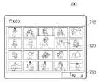
도 7a 및 도 7b는 도 5의 방법을 보다 구체적으로 설명하기 위한 도면이다. 도 7a 및 도 7b는 태그 기록 장치에서 수행되는 도 5의 단계(S510) 및 단계(S520)의 다른 실시 예를 나타내고 있다.7A and 7B illustrate the method of FIG. 5 in more detail. 7A and 7B illustrate another embodiment of steps S510 and S520 of FIG. 5 performed by the tag recording apparatus.
도 7a에서 태그 기록 장치(700)는 복수 개의 디스플레이 화면(710)을 디스플레이할 수 있으며, 이 중 특정 디스플레이 화면(720)이 사용자에 의해 선택될 수 있다. 여기서, 도 7b에서처럼, 사용자가 마우스 등을 이용하여 선택된 디스플레이 화면(720)을 태그 기록 영역(730)에 '드래그 앤 드롭(drag and drop)'할 수 있다. 이 경우, 사용자는 태그 기록 영역(730)에 옮겨진 선택된 디스플레이 화면(720)에 디스플레이 태그를 대향 배치하여 디스플레이 화면을 캡쳐할 수 있다.In FIG. 7A, the
이상에서는 본 발명의 바람직한 실시 예에 대하여 도시하고 설명하였지만, 당해 발명이 속하는 기술분야에서 통상의 지식을 가진 자라면, 누구든지 본 발명의 기술적 사상 및 범위를 벗어나지 않는 범주 내에서 본 발명의 바람직한 실시 예를 다양하게 변경할 수 있음은 물론이다. 따라서 본 발명은 특허청구범위에서 청구하는 본 발명의 요지를 벗어나지 않는다면 다양한 변형 실시가 가능할 것이며, 이러한 변형 실시들은 본 발명의 기술적 사상이나 전망으로부터 개별적으로 이해되어져서는 안될 것이다.Although the preferred embodiments of the present invention have been illustrated and described above, those skilled in the art to which the present invention pertains should preferably practice the present invention without departing from the spirit and scope of the present invention. Of course, the examples can be changed in various ways. Therefore, various modifications may be made without departing from the spirit of the invention as claimed in the claims, and such modifications should not be individually understood from the technical spirit or outlook of the invention.
도 1은 본 발명의 일 실시 예에 따른 디스플레이 태그를 나타내는 도면.1 is a view showing a display tag according to an embodiment of the present invention.
도 2는 도 1의 디스플레이 태그를 보다 구체적으로 나타내는 도면.FIG. 2 illustrates the display tag of FIG. 1 in more detail.
도 3은 본 발명의 일 실시 예에 따른 디스플레이 태그 구성 요소의 배치를 나타내는 도면.3 is a diagram illustrating an arrangement of display tag components according to an exemplary embodiment.
도 4는 본 발명의 일 실시 에에 따른 디스플레이 태그 시스템을 나타내는 도면.4 illustrates a display tag system according to an embodiment of the present invention.
도 5는 본 발명의 일 실시 에에 따른 디스플레이 태그 시스템의 태그 정보 기록 방법을 나타내는 흐름도.5 is a flowchart illustrating a tag information recording method of a display tag system according to an exemplary embodiment of the present invention.
도 6a 내지 도 6b는 도 5의 방법을 보다 구체적으로 설명하기 위한 도면.6A-6B illustrate the method of FIG. 5 in more detail.
도 7a 및 도 7b는 도 5의 방법을 보다 구체적으로 설명하기 위한 도면.7A and 7B illustrate the method of FIG. 5 in more detail.
* 도면의 주요 부분에 대한 설명 *Description of the main parts of the drawing
100, 420, 620 : 디스플레이 태그 110 : 센싱부100, 420, 620: display tag 110: sensing unit
120 : 디스플레이부 130 : 전원 발생부120: display unit 130: power generation unit
140 : 태그 정보 저장부 150 : 구동 회로부140: tag information storage unit 150: driving circuit unit
160 : 스위칭부 400 : 디스플레이 태그 시스템160: switching unit 400: display tag system
410, 610, 710 : 태그 기록 장치410, 610, 710: tag recording device
Claims (12)
Translated fromKoreanPriority Applications (5)
| Application Number | Priority Date | Filing Date | Title |
|---|---|---|---|
| KR1020080049236AKR20090123259A (en) | 2008-05-27 | 2008-05-27 | Display tag, display tag system including the same, and tag information recording method |
| US12/330,878US8400280B2 (en) | 2008-05-27 | 2008-12-09 | Display tag, display tag system having display tag, and method for writing display tag information |
| CNA2009100041867ACN101593267A (en) | 2008-05-27 | 2009-02-20 | Display label, display label system and method of writing display label information |
| US13/775,948US20130212518A1 (en) | 2008-05-27 | 2013-02-25 | Display tag, display tag system having display tag, and method for writing display tag information |
| US14/046,369US20140033114A1 (en) | 2008-05-27 | 2013-10-04 | Display tag, display tag system having display tag, and method for writing display tag information |
Applications Claiming Priority (1)
| Application Number | Priority Date | Filing Date | Title |
|---|---|---|---|
| KR1020080049236AKR20090123259A (en) | 2008-05-27 | 2008-05-27 | Display tag, display tag system including the same, and tag information recording method |
Publications (1)
| Publication Number | Publication Date |
|---|---|
| KR20090123259Atrue KR20090123259A (en) | 2009-12-02 |
Family
ID=41379088
Family Applications (1)
| Application Number | Title | Priority Date | Filing Date |
|---|---|---|---|
| KR1020080049236AAbandonedKR20090123259A (en) | 2008-05-27 | 2008-05-27 | Display tag, display tag system including the same, and tag information recording method |
Country Status (3)
| Country | Link |
|---|---|
| US (3) | US8400280B2 (en) |
| KR (1) | KR20090123259A (en) |
| CN (1) | CN101593267A (en) |
Cited By (1)
| Publication number | Priority date | Publication date | Assignee | Title |
|---|---|---|---|---|
| KR101505888B1 (en)* | 2013-09-23 | 2015-03-26 | 주식회사 비트컴퓨터 | Batteryless sensor display apparatus and batteryless local sensor system |
Families Citing this family (11)
| Publication number | Priority date | Publication date | Assignee | Title |
|---|---|---|---|---|
| US9122964B2 (en)* | 2010-05-14 | 2015-09-01 | Mark Krawczewicz | Batteryless stored value card with display |
| JP2011248768A (en)* | 2010-05-28 | 2011-12-08 | Sony Corp | Information processor, information processing system and program |
| JP5908239B2 (en)* | 2011-09-20 | 2016-04-26 | ソニー株式会社 | Display device |
| WO2013116669A1 (en) | 2012-02-03 | 2013-08-08 | Siemens Healthcare Diagnostic Inc. | Status displaying sample carrier |
| EP2860879B1 (en)* | 2012-05-25 | 2019-08-14 | Slim HMI Technology | Non-display signal coding method |
| USD766914S1 (en)* | 2013-08-16 | 2016-09-20 | Yandex Europe Ag | Display screen with graphical user interface having an image search engine results page |
| USD766913S1 (en)* | 2013-08-16 | 2016-09-20 | Yandex Europe Ag | Display screen with graphical user interface having an image search engine results page |
| KR20150092560A (en)* | 2014-02-05 | 2015-08-13 | 엘지전자 주식회사 | Mobile terminal and method for controlling the same |
| US12254369B2 (en)* | 2017-04-19 | 2025-03-18 | Sensormatic Electronics, LLC | Systems and methods for providing a security tag with synchronized display |
| EP3612986B1 (en)* | 2017-04-19 | 2024-02-14 | Sensormatic Electronics, LLC | Systems and methods for encoding security tags with dynamic display feature |
| CN113395471A (en)* | 2021-05-31 | 2021-09-14 | 广东长虹电子有限公司 | Television with static tag |
Family Cites Families (26)
| Publication number | Priority date | Publication date | Assignee | Title |
|---|---|---|---|---|
| US6924781B1 (en)* | 1998-09-11 | 2005-08-02 | Visible Tech-Knowledgy, Inc. | Smart electronic label employing electronic ink |
| JP2000306061A (en) | 1999-04-21 | 2000-11-02 | Haneda Hume Pipe Co Ltd | Id tag utilizing electromagnetic wave |
| JP2004517384A (en)* | 2000-09-21 | 2004-06-10 | アプライド・サイエンス・フィクション | Dynamic image correction and image system |
| KR101016529B1 (en)* | 2001-08-28 | 2011-02-24 | 소니 주식회사 | Information processing apparatus and method |
| US7180627B2 (en)* | 2002-08-16 | 2007-02-20 | Paxar Corporation | Hand-held portable printer with RFID read/write capability |
| JP3738761B2 (en)* | 2003-01-16 | 2006-01-25 | コニカミノルタビジネステクノロジーズ株式会社 | Composite image processing device |
| US20060146765A1 (en)* | 2003-02-19 | 2006-07-06 | Koninklijke Philips Electronics, N.V. | System for ad hoc sharing of content items between portable devices and interaction methods therefor |
| US7131584B2 (en)* | 2003-11-13 | 2006-11-07 | Eastman Kodak Company | Apparatus and means for updating a memory display |
| JP4341388B2 (en)* | 2003-11-28 | 2009-10-07 | セイコーエプソン株式会社 | Data communication system, identification tag, and elapsed period notification method |
| GB2409365B (en)* | 2003-12-19 | 2009-07-08 | Nokia Corp | Image handling |
| US7812860B2 (en)* | 2004-04-01 | 2010-10-12 | Exbiblio B.V. | Handheld device for capturing text from both a document printed on paper and a document displayed on a dynamic display device |
| JP4285277B2 (en)* | 2004-03-03 | 2009-06-24 | カシオ計算機株式会社 | Image capturing apparatus, electronic tag information and image data management system, and program |
| US7129938B2 (en)* | 2004-04-12 | 2006-10-31 | Nuelight Corporation | Low power circuits for active matrix emissive displays and methods of operating the same |
| US7229021B2 (en)* | 2004-06-07 | 2007-06-12 | Nokia Corporation | Indicia reader with synchronized light source and associated methods and computer program product |
| JP2006095886A (en)* | 2004-09-29 | 2006-04-13 | Canon Inc | Image forming apparatus and method |
| WO2006061890A1 (en)* | 2004-12-08 | 2006-06-15 | Fujitsu Limited | Tag information selecting method, electronic device, and program |
| JP2006229855A (en)* | 2005-02-21 | 2006-08-31 | Konica Minolta Photo Imaging Inc | Imaging apparatus |
| KR100746242B1 (en) | 2005-05-14 | 2007-08-08 | 아람테크 주식회사 | Active RDF Tag and RDF System Using Solar Cell |
| KR20070008988A (en)* | 2005-07-14 | 2007-01-18 | 주식회사 유컴테크놀러지 | Tire air pressure monitoring device using RFID system |
| US7900844B2 (en)* | 2005-09-12 | 2011-03-08 | Alden Ray M | Configurable RFID apparatus and process |
| JP2007079809A (en)* | 2005-09-13 | 2007-03-29 | Fuji Xerox Co Ltd | Electronic paper system |
| US7403797B2 (en)* | 2005-09-19 | 2008-07-22 | Silverbrook Research Pty Ltd | Obtaining a physical product via a coded surface |
| US7769345B2 (en)* | 2006-09-29 | 2010-08-03 | Sony Ericsson Mobile Communications Ab | Device and method for guiding a user to a communication position |
| US7775431B2 (en)* | 2007-01-17 | 2010-08-17 | Metrologic Instruments, Inc. | Method of and apparatus for shipping, tracking and delivering a shipment of packages employing the capture of shipping document images and recognition-processing thereof initiated from the point of shipment pickup and completed while the shipment is being transported to its first scanning point to facilitate early customs clearance processing and shorten the delivery time of packages to point of destination |
| US9507375B2 (en)* | 2007-06-05 | 2016-11-29 | Samsung Electronics Co., Ltd. | Display apparatus and method for recognizing location |
| US8130083B2 (en)* | 2007-10-31 | 2012-03-06 | Validfill Llc | System and method for displaying presentations based on codes written to and read from RFID tags |
- 2008
- 2008-05-27KRKR1020080049236Apatent/KR20090123259A/ennot_activeAbandoned
- 2008-12-09USUS12/330,878patent/US8400280B2/ennot_activeExpired - Fee Related
- 2009
- 2009-02-20CNCNA2009100041867Apatent/CN101593267A/enactivePending
- 2013
- 2013-02-25USUS13/775,948patent/US20130212518A1/ennot_activeAbandoned
- 2013-10-04USUS14/046,369patent/US20140033114A1/ennot_activeAbandoned
Cited By (1)
| Publication number | Priority date | Publication date | Assignee | Title |
|---|---|---|---|---|
| KR101505888B1 (en)* | 2013-09-23 | 2015-03-26 | 주식회사 비트컴퓨터 | Batteryless sensor display apparatus and batteryless local sensor system |
Also Published As
| Publication number | Publication date |
|---|---|
| US8400280B2 (en) | 2013-03-19 |
| US20130212518A1 (en) | 2013-08-15 |
| US20090295549A1 (en) | 2009-12-03 |
| CN101593267A (en) | 2009-12-02 |
| US20140033114A1 (en) | 2014-01-30 |
Similar Documents
| Publication | Publication Date | Title |
|---|---|---|
| KR20090123259A (en) | Display tag, display tag system including the same, and tag information recording method | |
| CN105980968B (en) | Micromachined Ultrasonic Transducers and Displays | |
| EP3382514B1 (en) | Electronic device with a fingerprint scan module | |
| US10395233B2 (en) | Mobile terminal and method for controlling the same | |
| US10044928B2 (en) | Mobile terminal and method for controlling the same | |
| CN105393261B (en) | The display of ultrasonic wave biological gage probe with periphery configuration | |
| KR102398836B1 (en) | Mobile terminal | |
| KR102353487B1 (en) | Mobile terminal and method for controlling the same | |
| US10191655B2 (en) | Mobile terminal and method for controlling the same | |
| US9148502B2 (en) | Portable multimedia playback apparatus, portable media playback system, and method for controlling operations thereof | |
| CN108883435A (en) | The drive scheme read for ultrasonic transducer pixel | |
| EP3144784B1 (en) | Mobile terminal and control method for the mobile terminal | |
| US20170322665A1 (en) | Mobile terminal and method for controlling the same | |
| CN109597520A (en) | Piezoelectric forces sense array | |
| CN105100388A (en) | Mobile terminal and method of controlling the same | |
| US10620766B2 (en) | Mobile terminal and method for controlling the same | |
| CN110413837A (en) | Video recommendation method and device | |
| US20170024736A1 (en) | Mobile terminal and method for controlling the same | |
| US20190005571A1 (en) | Mobile terminal and method for controlling same | |
| CN110609642B (en) | Electronic device control method, device, storage medium, and electronic device | |
| KR102415667B1 (en) | mobile terminal | |
| KR20250065275A (en) | Electronic shelf label and controlling method thereof | |
| KR102486275B1 (en) | Mobile terminal and method for controlling the same | |
| JP2013214301A (en) | Electronic paper and printing device | |
| US11503142B2 (en) | Mobile terminal |
Legal Events
| Date | Code | Title | Description |
|---|---|---|---|
| PA0109 | Patent application | Patent event code:PA01091R01D Comment text:Patent Application Patent event date:20080527 | |
| PG1501 | Laying open of application | ||
| A201 | Request for examination | ||
| PA0201 | Request for examination | Patent event code:PA02012R01D Patent event date:20130524 Comment text:Request for Examination of Application Patent event code:PA02011R01I Patent event date:20080527 Comment text:Patent Application | |
| E902 | Notification of reason for refusal | ||
| PE0902 | Notice of grounds for rejection | Comment text:Notification of reason for refusal Patent event date:20140328 Patent event code:PE09021S01D | |
| E701 | Decision to grant or registration of patent right | ||
| PE0701 | Decision of registration | Patent event code:PE07011S01D Comment text:Decision to Grant Registration Patent event date:20140928 | |
| PC1904 | Unpaid initial registration fee |