KR20090122461A - Efficient light injector - Google Patents
Efficient light injectorDownload PDFInfo
- Publication number
- KR20090122461A KR20090122461AKR1020097020191AKR20097020191AKR20090122461AKR 20090122461 AKR20090122461 AKR 20090122461AKR 1020097020191 AKR1020097020191 AKR 1020097020191AKR 20097020191 AKR20097020191 AKR 20097020191AKR 20090122461 AKR20090122461 AKR 20090122461A
- Authority
- KR
- South Korea
- Prior art keywords
- light
- light guide
- injector
- lambertian
- tapered solid
- Prior art date
- Legal status (The legal status is an assumption and is not a legal conclusion. Google has not performed a legal analysis and makes no representation as to the accuracy of the status listed.)
- Granted
Links
Images

Classifications
- G—PHYSICS
- G02—OPTICS
- G02B—OPTICAL ELEMENTS, SYSTEMS OR APPARATUS
- G02B6/00—Light guides; Structural details of arrangements comprising light guides and other optical elements, e.g. couplings
- G02B6/24—Coupling light guides
- G02B6/26—Optical coupling means
- G—PHYSICS
- G02—OPTICS
- G02B—OPTICAL ELEMENTS, SYSTEMS OR APPARATUS
- G02B6/00—Light guides; Structural details of arrangements comprising light guides and other optical elements, e.g. couplings
- G02B6/24—Coupling light guides
- G02B6/42—Coupling light guides with opto-electronic elements
- G02B6/4201—Packages, e.g. shape, construction, internal or external details
- G02B6/4202—Packages, e.g. shape, construction, internal or external details for coupling an active element with fibres without intermediate optical elements, e.g. fibres with plane ends, fibres with shaped ends, bundles
- G02B6/4203—Optical features
- G—PHYSICS
- G02—OPTICS
- G02B—OPTICAL ELEMENTS, SYSTEMS OR APPARATUS
- G02B6/00—Light guides; Structural details of arrangements comprising light guides and other optical elements, e.g. couplings
- G02B6/0001—Light guides; Structural details of arrangements comprising light guides and other optical elements, e.g. couplings specially adapted for lighting devices or systems
- G02B6/0005—Light guides; Structural details of arrangements comprising light guides and other optical elements, e.g. couplings specially adapted for lighting devices or systems the light guides being of the fibre type
- G02B6/0006—Coupling light into the fibre
- G—PHYSICS
- G02—OPTICS
- G02B—OPTICAL ELEMENTS, SYSTEMS OR APPARATUS
- G02B6/00—Light guides; Structural details of arrangements comprising light guides and other optical elements, e.g. couplings
- G02B6/24—Coupling light guides
- G02B6/42—Coupling light guides with opto-electronic elements
- G—PHYSICS
- G02—OPTICS
- G02B—OPTICAL ELEMENTS, SYSTEMS OR APPARATUS
- G02B6/00—Light guides; Structural details of arrangements comprising light guides and other optical elements, e.g. couplings
- G02B6/24—Coupling light guides
- G02B6/26—Optical coupling means
- G02B6/262—Optical details of coupling light into, or out of, or between fibre ends, e.g. special fibre end shapes or associated optical elements
- G—PHYSICS
- G02—OPTICS
- G02B—OPTICAL ELEMENTS, SYSTEMS OR APPARATUS
- G02B6/00—Light guides; Structural details of arrangements comprising light guides and other optical elements, e.g. couplings
- G02B6/24—Coupling light guides
- G02B6/42—Coupling light guides with opto-electronic elements
- G02B6/4201—Packages, e.g. shape, construction, internal or external details
- G02B6/4204—Packages, e.g. shape, construction, internal or external details the coupling comprising intermediate optical elements, e.g. lenses, holograms
- G02B6/4212—Packages, e.g. shape, construction, internal or external details the coupling comprising intermediate optical elements, e.g. lenses, holograms the intermediate optical element being a coupling medium interposed therebetween, e.g. epoxy resin, refractive index matching material, index grease, matching liquid or gel
Landscapes
- Physics & Mathematics (AREA)
- General Physics & Mathematics (AREA)
- Optics & Photonics (AREA)
- Planar Illumination Modules (AREA)
- Optical Couplings Of Light Guides (AREA)
- Non-Portable Lighting Devices Or Systems Thereof (AREA)
- Light Guides In General And Applications Therefor (AREA)
Abstract
Translated fromKoreanDescription
Translated fromKorean본 발명은 효율적인 광 주입기(light injector)에 관한 것이며, 더욱 상세하게는 램버시안 광원(lambertian light source)으로부터의 광을 효율적으로 투과시키는 테이퍼형 고체 광 주입기(tapered solid light injector)에 관한 것이다.FIELD OF THE INVENTION The present invention relates to efficient light injectors, and more particularly to tapered solid light injectors that efficiently transmit light from a Lambertian light source.
발광 다이오드(light emitting diode, LED)와 같은 고상(solid state) 광원은 흔히 그들의 작은 크기, 순수한 색상 및 긴 수명으로 인해 많은 응용에 있어서 바람직한 광원이다. 그러나, 패키징된 LED는 흔히 임의의 특정한 응용에 대해서는 최적화되지 못하며, 설계자는 특정 용도를 위해 광 출력을 수집 및 지향시키도록 모든 노력을 다한다. 효율적으로 이용되지 못하는 광은 사실상 낭비된다.Solid state light sources such as light emitting diodes (LEDs) are often the preferred light sources for many applications because of their small size, pure color and long lifetime. However, packaged LEDs are often not optimized for any particular application, and designers make every effort to collect and direct light output for a particular application. Light that is not used efficiently is wasted.
유리 또는 중합체와 같은 광학적으로 투과성인 재료는 광을 전파하는 도광체(light guide)로서 사용될 수 있다. 도광체는 흔히 광원으로부터 광을 수광하도록 구성된 적어도 하나의 표면 및 도광체를 통해 전파되는 광을 반사하기 위한 광학적으로 매끄러운 표면을 포함한다. 도광체의 통상의 예는 전통적으로 데이터 통신 산업에 사용되는 광섬유 및 더욱 최근에는 조명 목적으로 사용되는 도광체를 포함한다. 예를 들어, 미국 특허 제5,432,876호는 도광체를 이용하는 하나의 그러한 조명 장치를 개시한다. 이러한 장치에서, 광은 도광체의 적어도 하나의 단부 내로 주입되어, 도광체의 길이를 따른 미리설정된 위치 또는 위치들에서 도광체를 빠져나갈 수 있다. 광 추출 구조체 또는 노치가 도광체 내에 형성된다. 추출 구조체는 제1 및 제2 반사 표면을 형성하며, 이 표면들은 도광체를 통해 축방향으로 전파되는 광의 일부를 반경방향으로 반사시킨다. 반사된 광은 내부 전반사의 원리에 따라 도광체를 따른 연속되는 전파에 필요한 임계각 미만의 각도로 지향된다. 결과적으로, 반사된 광은 도광체로부터 추출된다.Optically transmissive materials such as glass or polymers can be used as light guides that propagate light. The light guide often includes at least one surface configured to receive light from a light source and an optically smooth surface for reflecting light propagating through the light guide. Typical examples of light guides include optical fibers traditionally used in the data communications industry and, more recently, light guides used for lighting purposes. For example, US Pat. No. 5,432,876 discloses one such lighting device using a light guide. In such a device, light may be injected into at least one end of the light guide to exit the light guide at a predetermined position or locations along the length of the light guide. A light extraction structure or notch is formed in the light guide. The extraction structure forms first and second reflective surfaces that reflect radially some of the light propagating axially through the light guide. The reflected light is directed at an angle below the critical angle required for continuous propagation along the light guide according to the principle of total internal reflection. As a result, the reflected light is extracted from the light guide.
램버시안 LED 광원으로부터 광을 수집하고 그 광을 도광체 내부로 결합시키는 것은 흔히 어려운데, 그 이유는 이러한 광이 LED로부터 모든 방향으로 방출되고, 이러한 광은 내부 전반사에 의해 효율적으로 유지될 수 있는 도광체의 개구수(numerical aperture) 내로 방향전환되어야 하기 때문이다. 단순한 반사기가 사용될 때, 반사 표면의 불완전 정반사는 광의 일정 부분이 매 반사 바운스(reflection bounce)마다 손실된다는 것을 의미한다. 램버시안 광원의 시준을 위해 설계된 반사기는 대개 원하는 출력각을 달성하기 위해 큰 종횡비(aspect ratio)를 필요로 한다. 이러한 종횡비는 또한 반사기를 가로지르는 광에 대한 상대적으로 많은 바운스 수를 의미하며, 더 많은 바운스는 더 많은 손실과 동일시된다.It is often difficult to collect light from a Lambertian LED light source and combine the light into the light guide, because this light is emitted from the LED in all directions, and the light can be efficiently maintained by total internal reflection. This is because it must be redirected into the numerical aperture of the sieve. When a simple reflector is used, incomplete specular reflection of the reflective surface means that some portion of the light is lost at every reflection bounce. Reflectors designed for the collimation of Lambertian light sources usually require large aspect ratios to achieve the desired output angle. This aspect ratio also means a relatively high number of bounces for light traversing the reflector, with more bounces equating to more losses.
본 발명은 램버시안 광원으로부터의 광의 효율적인 수집 및 투과에 관한 것이다. 특히, 본 발명은 효율을 최대화하기 위해 정반사 및 내부 전반사 둘 모두를 이용하는 소형의 반사성 원추형 광 수집기/주입기에 관한 것이다.The present invention relates to the efficient collection and transmission of light from a Lambertian light source. In particular, the present invention relates to a compact reflective conical light collector / injector that utilizes both specular reflection and total internal reflection to maximize efficiency.
제1 실시예에서, 광 주입기는 광 입력 단부, 대향하는 광 출력 단부, 및 이들 사이의 종방향 외부 표면을 형성하는 내부 전반사 표면을 갖는 테이퍼형 고체 도광체를 포함한다. 광 출력 단부는 광 입력 단부보다 더 큰 원주를 갖는다. 광 입력 단부는 개구 표면에 의해 형성되는, 테이퍼형 고체 도광체 내로 연장하는 개구를 포함한다. 정반사 층 또는 필름은 내부 전반사 표면에 인접하게 배치된다. 정반사 층 또는 필름과 내부 전반사 표면 사이의 간격이 제1 공기 간극을 형성한다. 개구는 램버시안 광원을 수용하도록 구성된다.In a first embodiment, the light injector comprises a tapered solid light guide having a light input end, an opposing light output end, and an internal total reflection surface forming a longitudinal outer surface therebetween. The light output end has a larger circumference than the light input end. The light input end includes an opening extending into the tapered solid light guide formed by the opening surface. The specular reflection layer or film is disposed adjacent to the total internal reflection surface. The spacing between the specular reflection layer or the film and the total internal reflection surface forms a first air gap. The opening is configured to receive a Lambertian light source.
다른 실시예에서, 광 주입기 조립체는 제1 단부, 대향하는 제2 단부, 및 이들 사이의 튜브 길이부를 갖는 긴 튜브를 포함한다. 긴 튜브는 내부 표면 및 내부 표면에 인접하게 배치되는 정반사 층 또는 필름을 갖는다. 제1 단부는 램버시안 광원을 수용하도록 구성된다. 테이퍼형 고체 도광체가 긴 튜브 내에 배치된다. 테이퍼형 고체 도광체는 광 입력 단부, 대향하는 광 출력 단부, 및 이들 사이의 종방향 외부 표면을 형성하는 내부 전반사 표면을 갖는다. 제1 공기 간극이 정반사 층 또는 필름과 내부 전반사 표면 사이의 간격에 의해 형성된다. 광 출력 단부는 광 입력 단부보다 더 큰 원주를 갖는다. 광 입력 단부는 개구 표면에 의해 형성되는, 테이퍼형 고체 도광체 내로 연장하는 개구를 포함한다. 개구는 램버시안 광원을 수용하도록 구성된다.In another embodiment, the light injector assembly includes an elongated tube having a first end, an opposing second end, and a tube length therebetween. The elongate tube has an inner surface and a specular layer or film disposed adjacent to the inner surface. The first end is configured to receive a Lambertian light source. A tapered solid light guide is disposed in the long tube. The tapered solid light guide has an internal total reflection surface that forms a light input end, an opposing light output end, and a longitudinal outer surface therebetween. The first air gap is formed by the spacing between the specular reflection layer or the film and the total internal reflection surface. The light output end has a larger circumference than the light input end. The light input end includes an opening extending into the tapered solid light guide formed by the opening surface. The opening is configured to receive a Lambertian light source.
추가의 실시예에서, 광 주입기 조립체를 형성하는 방법은 긴 튜브 및 테이퍼형 고체 도광체를 제공하는 단계를 포함한다. 긴 튜브는 제1 단부, 대향하는 제2 단부, 및 이들 사이의 튜브 길이부를 포함한다. 긴 튜브는 내부 표면 및 내부 표면에 인접하게 배치되는 경우 정반사 층 또는 필름을 갖는다. 램버시안 광원은 제1 단부에 인접하게 배치된다. 테이퍼형 고체 도광체는 광 입력 단부, 대향하는 광 출력 단부, 및 이들 사이의 종방향 외부 표면을 형성하는 내부 전반사 표면을 포함한다. 광 출력 표면은 광 입력 단부보다 더 큰 원주를 갖는다. 광 입력 단부는 개구 표면에 의해 형성되는, 테이퍼형 고체 도광체 내로 연장하는 개구를 포함한다. 방법은 램버시안 광원이 개구 내에 배치되고 제1 공기 간극에 의해 개구 표면으로부터 이격되도록 그리고 내부 전반사 표면이 제2 공기 간극에 의해 긴 튜브의 내부 표면으로부터 이격되도록 테이퍼형 고체 도광체를 긴 튜브 내로 삽입하여, 도광체 조립체를 형성하는 단계를 추가로 포함한다.In a further embodiment, a method of forming a light injector assembly includes providing an elongated tube and tapered solid light guide. The elongated tube includes a first end, an opposing second end, and a tube length therebetween. The long tube has an inner surface and a specular reflection layer or film when disposed adjacent to the inner surface. The Lambertian light source is disposed adjacent to the first end. The tapered solid light guide includes an internal total reflection surface that forms a light input end, an opposing light output end, and a longitudinal outer surface therebetween. The light output surface has a larger circumference than the light input end. The light input end includes an opening extending into the tapered solid light guide formed by the opening surface. The method inserts a tapered solid light guide into the long tube such that the Lambertian light source is disposed in the opening and spaced apart from the opening surface by the first air gap and the total internal reflection surface is spaced from the inner surface of the long tube by the second air gap. Thereby forming the light guide assembly.
본 명세서에 설명된 광 주입기 및 광 주입기 조립체를 포함하는 조명 조립체가 또한 설명된다. 이들 조립체는 테이퍼형 고체 도광체의 광 출력 단부로부터 방출되는 광을 수광하도록 위치되는 도광체 광 입력 단부를 갖는 긴 원통형 도광체를 포함한다. 몇몇 실시예에서, 이들 광 주입기 및 긴 원통형 도광체는 일체형 요소를 형성한다.Also described are lighting assemblies that include the light injectors and light injector assemblies described herein. These assemblies include an elongated cylindrical light guide having a light guide light input end positioned to receive light emitted from the light output end of the tapered solid light guide. In some embodiments, these light injectors and the elongate cylindrical light guide form an integral element.
본 발명은 첨부 도면과 관련하여 본 발명의 다양한 실시예에 대한 하기의 상세한 설명을 고려하여 더욱 완벽하게 이해될 수 있다.The invention may be more fully understood in view of the following detailed description of various embodiments of the invention in connection with the accompanying drawings.
도 1은 예시적인 조명 조립체의 개략 단면도.1 is a schematic cross-sectional view of an exemplary lighting assembly.
도 2는 예시적인 광 주입기 조립체의 단면 사시도.2 is a cross-sectional perspective view of an exemplary light injector assembly.
도면은 반드시 축척대로 도시된 것은 아니다. 도면에 사용된 동일한 도면 부호는 동일한 구성요소를 지칭한다. 그러나, 주어진 도면에서 구성요소를 지칭하기 위한 도면 부호의 사용은 동일한 도면 부호로 표시된 다른 도면의 구성요소를 제한하고자 하는 것이 아님을 이해할 것이다.The drawings are not necessarily drawn to scale. Like numbers used in the drawings refer to like elements. However, it will be understood that the use of a reference numeral to refer to a component in a given figure is not intended to limit the components of another figure denoted by the same reference numeral.
이하의 설명에서, 본 명세서의 일부를 형성하고 예로서 몇몇 특정 실시예가 도시된 첨부 도면을 참조한다. 다른 실시예들이 고려되며 본 발명의 사상 또는 범주로부터 벗어남이 없이 이루어질 수 있음을 이해해야 한다. 따라서, 이하의 상세한 설명은 제한하는 의미로 고려되지 않아야 한다.In the following description, reference is made to the accompanying drawings, which form a part hereof, and in which, by way of illustration, certain specific embodiments are shown. It is to be understood that other embodiments are contemplated and may be made without departing from the spirit or scope of the invention. Accordingly, the following detailed description should not be considered in a limiting sense.
본 명세서에 사용된 모든 과학적이고 기술적인 용어는 달리 명시되지 않는 한 당업계에서 통상적으로 사용되는 의미를 갖는다. 본 명세서에 제공되는 정의는 본 명세서에서 자주 사용되는 소정의 용어들에 대한 이해를 용이하게 하기 위한 것이며 본 발명의 범주를 제한하려는 것은 아니다.All scientific and technical terms used herein have the meanings commonly used in the art unless otherwise specified. The definitions provided herein are intended to facilitate understanding of certain terms frequently used herein and are not intended to limit the scope of the invention.
달리 지시되지 않는 한, 명세서 및 청구의 범위에서 사용되는, 특징부 크기, 양 및 물리적 특성을 표현하는 모든 수치는 모든 경우 "약"이라는 용어에 의해 수식되는 것으로 이해되어야 한다. 따라서, 반대로 지시되지 않는 한, 전술한 명세서 및 첨부된 청구의 범위에 기술된 수치적 파라미터는 근사치이며, 이 근사치는 본 명세서에 개시된 교시 내용을 이용하는 당업자가 얻고자 하는 원하는 특성에 따라 달라질 수 있다.Unless otherwise indicated, all numbers expressing feature sizes, quantities, and physical properties, as used in the specification and claims, are to be understood as being modified in all instances by the term "about." Accordingly, unless indicated to the contrary, the numerical parameters set forth in the foregoing specification and the appended claims are approximations, which may vary depending upon the desired properties desired by those skilled in the art using the teachings disclosed herein. .
종점(endpoint)에 의한 수치 범위의 언급은 그 범위 내에 포함되는 모든 수(예를 들어, 1 내지 5는 1, 1.5, 2, 2.75, 3, 3.80, 4 및 5를 포함함)와 그 범위 내의 임의의 범위를 포함한다.Reference to a numerical range by endpoint refers to any number within the range (eg, 1 to 5 includes 1, 1.5, 2, 2.75, 3, 3.80, 4, and 5) and within that range. It includes any range.
본 명세서 및 첨부된 청구의 범위에서 사용되는 바와 같이, 단수 형태("a", "an" 및 "the")는 그 내용이 명백하게 다르게 지시하지 않는 한 복수의 지시 대상을 갖는 실시예를 포함한다.As used in this specification and the appended claims, the singular forms “a,” “an,” and “the” include embodiments having plural referents, unless the content clearly dictates otherwise. .
본 발명은 램버시안 광원으로부터의 광의 효율적인 수집 및 투과에 관한 것이다. 특히, 본 발명은 램버시안 광원으로부터 방출되는 광의 효율적인 수집 및 투과를 최대화하기 위해 정반사 및 내부 전반사(TIR) 둘 모두를 이용하는 소형의 반사성 원추형 광 수집기/주입기에 관한 것이다. 그러나, 본 발명은 이와 같이 제한되지 않으며, 본 발명의 다양한 태양에 대한 이해를 이하에 제공된 예들의 논의를 통해 얻게 될 것이다.The present invention relates to the efficient collection and transmission of light from a Lambertian light source. In particular, the present invention relates to a compact reflective conical light collector / injector that utilizes both specular reflection and total internal reflection (TIR) to maximize the efficient collection and transmission of light emitted from a Lambertian light source. However, the invention is not so limited, and an understanding of various aspects of the invention will be gained through a discussion of the examples provided below.
소형의 반사성 원추형 광 주입기/수집기는 고효율의 정반사기에 의해 둘러싸인 테이퍼형 광학 요소이다. 원추 형상의 광학 요소는 공기 간극에 의해 반사기로부터 분리된다. 램버시안 광원은 원추 형상의 광학 요소의 좁은 단부 내의 개구 내에 배치된다. 몇몇 실시예에서, 램버시안 광원은 공기 간극에 의해 개구 표면으로부터 분리된다. 이러한 원추 형상의 광학 요소 구성으로 인해, 광이 원추 형상의 광학 요소를 가로지를 때, 바운스각의 연속적인 감소가 일어난다. 결과적으로, 수집되는 광은 원추 형상의 광학 요소의 내부 전반사를 위한 임계각 요건을 충족할 것이다. 일단 광이 원추 형상의 광학 요소 내부로 결합되면, 후속하는 반사 바운스는 TIR에 기인할 것이며 무손실일 것이다.The compact reflective conical light injector / collector is a tapered optical element surrounded by a high efficiency specular reflector. The conical optical element is separated from the reflector by an air gap. The Lambertian light source is disposed in an opening in the narrow end of the conical shaped optical element. In some embodiments, the Lambertian light source is separated from the opening surface by an air gap. Due to this conical optical element configuration, a continuous reduction in the bounce angle occurs when light traverses the conical optical element. As a result, the collected light will meet the critical angle requirement for total internal reflection of the conical shaped optical element. Once the light is coupled into the conical optical element, subsequent reflection bounce will be due to the TIR and will be lossless.
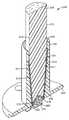
도 1은 광 주입기(110) 및 긴 원통형 도광체(105)를 포함하는 조명 조립 체(100)를 도시한다. 광 주입기(110)는 도광체(105)에 결합된다. 많은 실시예에서, 광 주입기(110)는 광 주입기(110)와 도광체(105) 사이의 계면(107)에서 굴절률 정합 겔 또는 접착제에 의해 도광체(105)에 결합된다. 몇몇 실시예에서, 주입기(110)는 일체형 요소 또는 본체를 형성하도록 도광체(105)의 단부 상에 형성될 수 있으며, 이에 따라 광학 계면, 및 주입기를 도광체에 결합 또는 접합시킬 필요성을 제거할 수 있다.1 shows a
광 주입기(110)는 광 입력 단부(114), 대향하는 광 출력 단부(116), 및 이들 사이의 종방향 외부 표면을 형성하는 내부 전반사 표면(118)을 갖는 테이퍼형 고체 도광체(112)를 포함한다. 광 출력 단부(116)는 광 입력 단부(114)보다 더 큰 원주를 갖는다. 광 입력 단부(114)는 테이퍼형 고체 도광체(112) 내부로의 광의 투과를 증가시키는 임의의 형상을 가질 수 있는 개구 표면(113)에 의해 형성되는, 테이퍼형 고체 도광체(112) 내로 연장하는 개구(111)를 포함한다. 많은 실시예에서, 개구 표면(113)은 1 주기의 코사인 곡선, 반구형 개구 표면 등과 같은 곡선형 개구 표면(113)이다. 몇몇 실시예에서, 개구 표면(113)은 일반적으로 램버시안 광원(120)의 외부 표면에 대응하여, 램버시안 광원(120)이 개구 표면(113)과 정합될 수 있다.The
테이퍼형 고체 도광체(112)는 임의의 유용한 형상을 가질 수 있다. 많은 실시예에서, 테이퍼형 고체 도광체(112)는 원추 형상 또는 장방형 원추 형상을 가질 수 있다(예를 들어, 광 출력 단부(116)에서 타원형 단면 및 광 입력 단부(114)에서 타원형 또는 원형 단면을 가짐). 원추 형상은 긴 원통 도광체 내부로 광을 주입하 는 데 유용할 수 있다. 장방형 원추 형상은 타원형 또는 직사각형 단면을 갖는 도광체 내부로 광을 주입하는 데 유용할 수 있다. 광 입력 단부(114)로부터 광 출력 단부(116)로 테이퍼지는 정도는 광 출력 단부(116)로부터 특정한 광 출력 빔 형상을 달성하도록 선택될 수 있다.The tapered solid
몇몇 실시예에서, 테이퍼형 고체 도광체(112)는 램버시안 광원(120)에 의해 방출되는 광으로 광 출력 단부(116) 개구수를 실질적으로(즉, 95% 이상) 채우도록 구성된다. 이는 몇몇 실시예에서, 20 내지 50도 또는 20 내지 35도의 범위로 테이퍼각(테이퍼형 고체 도광체(112)의 내부 전반사 표면(118) 및 종축에 의해 형성됨)을 선택함으로써 달성될 수 있다. 이들 테이퍼형 고체 도광체(112)는 분산된 광 빔을 필요로 하는 응용, 예를 들어 도광체 디스플레이 또는 조명 응용에 유용할 수 있다.In some embodiments, the tapered solid
몇몇 실시예에서, 테이퍼형 고체 도광체(112)는 램버시안 광원(120)에 의해 광 출력 단부(116)로부터 방출되는 광을 실질적으로(즉, 95% 이상) 시준하도록 구성된다. 이는 몇몇 실시예에서, 10 내지 20도의 범위로 테이퍼각(전술됨)을 선택함으로써 달성될 수 있다. 이들 테이퍼형 고체 도광체(112)는 시준된 광 빔을 필요로 하는 응용, 예를 들어 광 투사 응용에 유용할 수 있다.In some embodiments, tapered solid
몇몇 실시예에서, 테이퍼형 고체 도광체(112)는 램버시안 광원(120)에 의해 광 출력 단부(116)로부터 방출되는 광을 제1 축을 따라 실질적으로(즉, 95% 이상) 시준하고, 램버시안 광원(120)에 의해 광 출력 단부(116)로부터 방출되는 광을 제1 축에 직교하는 제2 축을 따라 실질적으로 시준하도록 구성된다. 이는 몇몇 실시예 에서, 광 출력 단부(116)에 장방형, 타원형 또는 직사각형 단면을 형성하는 테이퍼각(전술됨)을 선택함으로써 달성될 수 있다. 이들 테이퍼형 고체 도광체(112)는 하나의 축을 따라 분산된 광 빔을 그리고 직교하는 축을 따라 시준된 광 빔을 필요로 하는 응용, 예를 들어 도광체 디스플레이 또는 조명 응용에 유용할 수 있다.In some embodiments, the tapered solid
정반사 층 또는 필름(115)은 내부 전반사 표면(118)에 인접하지만 그로부터 이격되어 배치된다. 정반사 층 또는 필름(115)과 내부 전반사 표면(118) 사이의 간격이 제1 공기 간극(117)을 형성한다. 많은 실시예에서, 공기 간극(117)은 내부 전반사 표면(118)을 완전하게 둘러싼다.The specular reflection layer or
램버시안 광원(120)은 개구(111) 내에 배치된다. 많은 실시예에서, 개구 표면(113)과 램버시안 광원(120) 사이의 간격이 제2 공기 간극(119)을 형성한다. 몇몇 실시예에서, 공기 간극(119)은 램버시안 광원(120)을 완전하게 둘러싼다. 다른 실시예에서, 개구 표면(113)과 램버시안 광원(120) 사이의 간격은, 굴절률 정합 겔 또는 접착제로 채워지고 그에 따라 개구 표면(113)과 램버시안 광원(120)을 광학적으로 결합시키는 간극(119)이다.The Lambertian
몇몇 실시예에서, 개구(111) 표면(113)은 일반적으로 램버시안 광원(120)의 외부 표면에 대응하여, 램버시안 광원(120)이 개구(111) 표면(113)과 정합된다. 몇몇 실시예에서, 테이퍼형 고체 도광체(112)는 램버시안 광원(120)과 함께 성형 또는 형성될 수 있으며, 그에 따라 개구(111) 표면(113)은 일반적으로 램버시안 광원(120)의 외부 표면에 대응하는 상보적인 개구(111) 표면(113)을 달성하기 위해 램버시안 광원(120) 상에 형성될 수 있다.In some embodiments, the
도광체(105) 및 테이퍼형 고체 도광체(112)는 임의의 유용한 상보적인 형상일 수 있다. 많은 실시예에서, 테이퍼형 고체 도광체(112)는 원추 형상이고, 도광체(105)는 긴 원통 형상이다.The
도광체(105) 및 테이퍼형 고체 도광체(112)는 유리, 석영, 및/또는 중합체 재료와 같은 임의의 유용한 광 투과성 재료로 독립적으로 형성될 수 있다. 유용한 중합체 재료에는 폴리에스테르, 폴리카르보네이트, 폴리이미드, 폴리아크릴레이트, 폴리메틸스티렌, 실리콘, 예컨대 GE의 인비시실(Invisisil) 액상 사출 성형성 재료 등이 포함된다. 도광체(105) 및 테이퍼형 고체 도광체(112)는 개별 부품이든지 조합된 부품이든지 간에 사출 성형, 주조, 압출에 의해, 또는 고체 재료를 기계가공함으로써, 또는 임의의 다른 적합한 공정에 의해 제조될 수 있다. 많은 실시예에서, 도광체(105) 및 테이퍼형 고체 도광체(112)는 1.4 이상, 또는 1.5 이상, 또는 1.4 내지 1.7의 범위의 굴절률을 갖는 재료로 형성된다.The
본 명세서에 설명된 광 주입기(110)는 내부 전반사 표면(118)에 인접하지만 밀접하거나 광학적으로 접촉하지 않게 배치되는 정반사 층(115)을 포함한다. 정반사 층은 내부 전반사 표면(118)과 밀접하게 접촉하지 않기 때문에, 광은 대부분 직접 방출을 통해 또는 내부 전반사(TIR)를 통해 광 주입기(110) 외부로 이동한다. 내부 전반사 표면(118)을 통해 빠져나가는 광은 정반사 층(115)을 통해 정반사된다. 이러한 구성은 광 주입기(110)의 효율을 개선하는 것으로 밝혀졌다. 정반사 층(115)은 예를 들어 금속 또는 유전체 재료와 같은 임의의 유용한 정반사 층일 수 있다. 예시적인 정반사 금속 층 또는 필름은 은 도금된 미러, 폴리싱된 금속 또는 금속화된 표면을 포함한다.The
많은 실시예에서, 본 명세서에 설명된 광 주입기는 정반사 층(115)으로서의 다층 광학 필름의 고유의 유리한 특성을 이용한다. 그러한 필름의 이점, 특징 및 제조는 본 명세서에 참고로 포함된 미국 특허 제5,882,774호에 설명되어 있다. 다층 광학 필름은 예를 들어 고효율 스펙트럴 미러(spectral mirror)로서 유용하다. 다층 광학 필름의 특성 및 특징에 대한 비교적 간략한 설명이 이하 제공된다. 많은 실시예에서, 다층 중합체 미러 필름은 미국 미네소타주 세인트 폴 소재의 쓰리엠 컴퍼니(3M Company)로부터 입수가능한 비퀴티(Vikuiti)(등록상표) ESR 필름이다. 이러한 다층 중합체 미러 필름은 다층 중합체 필름에 임의의 각도로 입사하는 광의 95% 초과를 반사한다.In many embodiments, the light injectors described herein utilize the inherent beneficial properties of the multilayer optical film as the
본 발명과 함께 사용되는 바와 같은 다층 광학 미러 필름은 축외(off-axis) 광 및 수직 광선에 대한 높은 반사율(reflectivity)뿐만 아니라 입사 광에 대한 상대적으로 낮은 흡수율(absorption)을 나타낸다. 다층 광학 필름의 고유의 특성 및 이점은 공지된 광 주입기 시스템과 비교할 때 낮은 흡수 손실을 나타내는 매우 효율적인 광 주입기를 설계하는 기회를 제공한다. 예시적인 다층 광학 미러 필름은 본 명세서에 참고로 포함된 미국 특허 제6,924,014호에 설명되어 있다(예 1 및 예 2 참조).Multilayer optical mirror films as used in conjunction with the present invention exhibit high reflectivity for off-axis light and vertical light as well as relatively low absorption for incident light. The inherent properties and advantages of multilayer optical films offer the opportunity to design highly efficient light injectors that exhibit low absorption losses compared to known light injector systems. Exemplary multilayer optical mirror films are described in US Pat. No. 6,924,014, which is incorporated herein by reference (see Examples 1 and 2).
예시적인 다층 광학 미러 필름은 적어도 2개의 재료의 교번하는 층들을 갖는 다층 스택(stack)을 포함한다. 재료들 중 적어도 하나는 응력 유도 복굴절 특성을 가져서, 재료의 굴절률(n)이 신장 공정에 의해 영향을 받는다. 층들 사이의 각각 의 경계에서의 굴절률 차이는 광선의 일부를 반사되게 할 것이다. 단축 내지 이축 배향의 범위에 걸쳐 다층 스택을 신장시킴으로써, 상이하게 배향된 평면-편광된 입사 광에 대한 일정 범위의 반사율을 갖도록 필름이 생성된다. 따라서, 다층 스택은 미러로서 유용하게 제조될 수 있다. 이와 같이 구성된 다층 광학 필름은 매우 크거나 존재하지 않는 브루스터각(Brewster angle)(층 계면들 중 임의의 계면에 입사된 광에 대해 반사율이 0이 되는 각도)을 나타낸다. 그 결과, 이들 중합체 다층 스택은 넓은 대역폭에 걸쳐 s 및 p 편광된 광 둘 모두에 대해 높은 반사율을 갖고, 광범위한 각도에 걸쳐 반사가 달성될 수 있다.Exemplary multilayer optical mirror films include a multilayer stack having alternating layers of at least two materials. At least one of the materials has a stress induced birefringence characteristic such that the refractive index n of the material is affected by the stretching process. The difference in refractive index at each boundary between the layers will cause some of the light rays to be reflected. By stretching the multilayer stack over a range of uniaxial to biaxial orientations, the film is produced to have a range of reflectances for differently oriented planar-polarized incident light. Thus, the multilayer stack can be usefully manufactured as a mirror. The multilayer optical film thus constructed exhibits a very large or nonexistent Brewster angle (an angle at which the reflectance is zero for light incident at any of the layer interfaces). As a result, these polymer multilayer stacks have high reflectivity for both s and p polarized light over a wide bandwidth, and reflection can be achieved over a wide range of angles.
다층 중합체 미러 필름은 수십, 수백 또는 수천 개의 층을 포함할 수 있고, 각각의 층은 다수의 상이한 재료들 중 임의의 재료로부터 제조될 수 있다. 특정 스택에 대한 재료 선택을 결정하는 특징은 스택의 원하는 광학 성능에 따른다. 스택은 스택 내에 존재하는 층만큼의 많은 재료를 포함할 수 있다. 용이한 제조를 위해, 바람직한 얇은 광학 필름 스택은 단지 몇 개의 상이한 재료만을 포함한다. 재료들 또는 상이한 물리적 특성을 갖는 화학적으로 동일한 재료들 사이의 경계는 급하거나 점진적일 수 있다. 해석해(analytical solution)를 갖는 일부 단순한 경우를 제외하고는, 연속적으로 변화하는 굴절률을 갖는 후자 유형의 층상(stratified) 매질의 분석은 급한 경계를 갖지만 인접한 층들 사이의 특성이 단지 적게 변화하는 훨씬 더 많은 개수의 더 얇고 균일한 층들로서 보통 처리된다. 많은 실시예에서, 다층 중합체 미러 필름은 저/고 굴절률 쌍의 필름 층을 포함하고, 여기서 각각의 저/고 굴절률 쌍의 층은 반사하도록 설계된 대역의 중심 파장의 1/2의 조합된 광학 두께를 갖는다.Multilayer polymeric mirror films can include tens, hundreds, or thousands of layers, each layer can be made from any of a number of different materials. The characteristics that determine the material selection for a particular stack depend on the desired optical performance of the stack. The stack can include as many materials as the layers present in the stack. For ease of manufacture, preferred thin optical film stacks contain only a few different materials. The boundary between materials or chemically identical materials having different physical properties may be hurried or gradual. With the exception of some simple cases with analytical solution, the analysis of the latter type of stratified media with continuously varying refractive indices has a much more rapid boundary but with much smaller changes between adjacent layers. It is usually treated as a number of thinner and more uniform layers. In many embodiments, the multilayer polymer mirror film comprises a low / high refractive index pair of film layers, wherein each low / high refractive index pair layer has a combined optical thickness of one half of the center wavelength of the band designed to reflect. Have
다층 중합체 미러 필름의 경우, 각각의 편광의 광 및 입사 평면에 대한 원하는 평균 투과율은 일반적으로 반사 미러 필름의 의도된 용도에 따른다. 다층 미러 필름을 생성하는 하나의 방법은 저/고 굴절률 쌍의 고굴절률 층으로서 복굴절 재료를 포함하는 다층 스택을 이축 신장하는 것이다. 고효율 반사 필름의 경우, 가시광 스펙트럼(400-700 ㎚)에 걸친 수직 입사시 각각의 신장 방향에 따른 평균 투과율은 바람직하게는 10% 미만(90% 초과의 반사율), 또는 5% 미만(95% 초과의 반사율), 또는 2% 미만(98% 초과의 반사율), 또는 1% 미만(99% 초과의 반사율)이다. 400-700 ㎚로부터의 법선으로부터 60도에서의 평균 투과율은 바람직하게는 20% 미만(80% 초과의 반사율), 또는 10% 미만(90% 초과의 반사율), 또는 5% 미만(95% 초과의 반사율), 또는 2% 미만(98% 초과의 반사율), 또는 1% 미만(99% 초과의 반사율)이다.In the case of a multilayer polymer mirror film, the desired average transmission for each plane of light and the plane of incidence generally depends on the intended use of the reflective mirror film. One method of producing a multilayer mirror film is to biaxially stretch a multilayer stack comprising birefringent material as a high index layer of low / high index pairs. For highly efficient reflective films, the average transmission along each direction of stretching at normal incidence over the visible light spectrum (400-700 nm) is preferably less than 10% (> 90% reflectivity), or less than 5% (> 95%). Reflectance), or less than 2% (> 98% reflectivity), or <1% (> 99% reflectance). The average transmission at 60 degrees from the normal from 400-700 nm is preferably less than 20% (greater than 80% reflectivity), or less than 10% (greater than 90% reflectance), or less than 5% (greater than 95%). Reflectance), or less than 2% (> 98% reflectivity), or <1% (> 99% reflectance).
전술한 미국 특허 제5,882,774호에 설명된 설계 고려 사항에 의해, 당업자는 원하는 굴절률 관계를 생성하도록 선택된 조건 하에서 처리될 때 광범위한 재료가 다층 중합체 반사 미러 필름을 형성하는 데 사용될 수 있다는 것을 쉽게 알 수 있을 것이다. 원하는 굴절률 관계는 (예를 들어, 유기 중합체의 경우) 필름 형성 중 또는 그 후의 신장, (예를 들어 액정 재료의 경우) 압출, 또는 코팅을 포함하는 다양한 방법으로 달성될 수 있다. 또한, 2개의 재료는 공압출될 수 있도록 유사한 유동학적 특성(예를 들어, 용융 점도)을 갖는 것이 바람직하다.By virtue of the design considerations described in U.S. Patent No. 5,882,774 described above, one of ordinary skill in the art will readily recognize that a wide range of materials can be used to form a multilayer polymeric reflective mirror film when treated under conditions selected to produce the desired refractive index relationship. will be. The desired refractive index relationship can be achieved in a variety of ways, including stretching during or after film formation (eg for organic polymers), extrusion (eg for liquid crystal materials), or coating. In addition, the two materials preferably have similar rheological properties (eg, melt viscosity) so that they can be coextruded.
일반적으로, 적절한 조합이 제1 재료로서 결정질 또는 반결정질 재료, 바람 직하게는 중합체를 선택함으로써 달성될 수 있다. 다음에, 제2 재료는 결정질, 반결정질 또는 비결정질일 수 있다. 제2 재료는 제1 재료와는 반대의 복굴절을 가질 수 있다. 또는, 제2 재료는 복굴절을 갖지 않거나, 제1 재료보다 작은 복굴절을 가질 수 있다. 적합한 재료의 구체예에는 폴리에틸렌 나프탈레이트(PEN) 및 그 이성체(예를 들어, 2,6-, 1,4-, 1,5-, 2,7-, 및 2,3-PEN), 폴리알킬렌 테레프탈레이트(예를 들어, 폴리에틸렌 테레프탈레이트, 폴리부틸렌 테레프탈레이트, 및 폴리-1,4-사이클로헥산다이메틸렌 테레프탈레이트), 폴리이미드(예를 들어, 폴리아크릴릭 이미드), 폴리에테르이미드, 어탁틱(atactic) 폴리스티렌, 폴리카르보네이트, 폴리메타크릴레이트(예를 들어, 폴리아이소부틸 메타크릴레이트, 폴리프로필메타크릴레이트, 폴리에틸메타크릴레이트, 및 폴리메틸메타크릴레이트), 폴리아크릴레이트(예를 들어, 폴리부틸아크릴레이트 및 폴리메틸아크릴레이트), 신디오탁틱(syndiotactic) 폴리스티렌(sPS), 신디오탁틱 폴리-알파-메틸 스티렌, 신디오탁틱 폴리다이클로로스티렌, 이들 폴리스티렌들 중 임의의 폴리스티렌의 공중합체 및 블렌드, 셀룰로오스 유도체(예를 들어, 에틸 셀룰로오스, 셀룰로오스 아세테이트, 셀룰로오스 프로피오네이트, 셀룰로오스 아세테이트 부티레이트, 및 셀룰로오스 니트레이트), 폴리알킬렌 중합체(예를 들어, 폴리에틸렌, 폴리프로필렌, 폴리부틸렌, 폴리아이소부틸렌, 및 폴리(4-메틸)펜텐), 플루오르화 중합체(예를 들어, 퍼플루오로알콕시 수지, 폴리테트라플루오로에틸렌, 플루오르화 에틸렌-프로필렌 공중합체, 폴리비닐리덴 플루오라이드, 및 폴리클로로트라이플루오로에틸렌), 염소화 중합체(예를 들어, 폴리비닐리덴 클로라이드 및 폴리비닐클로라이드), 폴리설폰, 폴리에 테르설폰, 폴리아크릴로니트릴, 폴리아미드, 실리콘 수지, 에폭시 수지, 폴리비닐아세테이트, 폴리에테르-아미드, 이오노머 수지, 탄성중합체(예를 들어, 폴리부타디엔, 폴리아이소프렌, 및 네오프렌), 및 폴리우레탄이 포함된다. 또한 적합한 것은 공중합체, 예를 들어 PEN의 공중합체(예를 들어, 2,6-, 1,4-, 1,5-, 2,7-, 및/또는 2,3-나프탈렌 다이카르복실산 또는 그 에스테르와, (a) 테레프탈산 또는 그 에스테르; (b) 아이소프탈산 또는 그 에스테르; (c) 프탈산 또는 그 에스테르; (d) 알칸 글리콜; (e) 사이클로알칸 글리콜(예를 들어, 사이클로헥산 다이메탄 다이올); (f) 알칸 다이카르복실산; 및/또는 (g) 사이클로알칸 다이카르복실산(예를 들어, 사이클로헥산 다이카르복실산)과의 공중합체), 폴리알킬렌 테레프탈레이트의 공중합체(예를 들어, 테레프탈산 또는 그 에스테르와, (a) 나프탈렌 다이카르복실산 또는 그 에스테르; (b) 아이소프탈산 또는 그 에스테르; (c) 프탈산 또는 그 에스테르; (d) 알칸 글리콜; (e) 사이클로알칸 글리콜(예를 들어, 사이클로헥산 다이메탄 다이올); (f) 알칸 다이카르복실산; 및/또는 (g) 사이클로알칸 다이카르복실산(예를 들어, 사이클로헥산 다이카르복실산)과의 공중합체), 및 스티렌 공중합체(예를 들어, 스티렌-부타디엔 공중합체 및 스티렌-아크릴로니트릴 공중합체), 4,4'-바이벤조산 및 에틸렌 글리콜이다. 더욱이, 각각의 개별 층은 2가지 이상의 전술된 중합체들 또는 공중합체들의 블렌드(예를 들어, sPS 및 어탁틱 폴리스티렌의 블렌드)를 포함할 수 있다. 설명된 coPEN은 또한 적어도 하나의 성분이 나프탈렌 다이카르복실산을 기재로 하는 중합체이고 다른 성분이 기타 폴리에스테르 또는 폴리카르보네이트, 예를 들어 PET, PEN 또는 co-PEN인 펠렛의 블렌드일 수 있다.In general, a suitable combination can be achieved by selecting a crystalline or semicrystalline material, preferably a polymer, as the first material. The second material can then be crystalline, semicrystalline or amorphous. The second material may have a birefringence opposite to the first material. Alternatively, the second material may have no birefringence or may have a smaller birefringence than the first material. Specific examples of suitable materials include polyethylene naphthalate (PEN) and isomers thereof (eg, 2,6-, 1,4-, 1,5-, 2,7-, and 2,3-PEN), polyalkyls Lene terephthalate (eg, polyethylene terephthalate, polybutylene terephthalate, and poly-1,4-cyclohexanedimethylene terephthalate), polyimide (eg, polyacrylic imide), polyetherimide, Atactic polystyrene, polycarbonate, polymethacrylate (eg, polyisobutyl methacrylate, polypropylmethacrylate, polyethylmethacrylate, and polymethylmethacrylate), polyacrylates Rates (e.g., polybutylacrylate and polymethylacrylate), syndiotactic polystyrene (sPS), syndiotactic poly-alpha-methyl styrene, syndiotactic polydichlorostyrene, of these polystyrenes random Copolymers and blends of ristyrene, cellulose derivatives (e.g. ethyl cellulose, cellulose acetate, cellulose propionate, cellulose acetate butyrate, and cellulose nitrate), polyalkylene polymers (e.g. polyethylene, polypropylene, Polybutylene, polyisobutylene, and poly (4-methyl) pentene), fluorinated polymers (eg, perfluoroalkoxy resins, polytetrafluoroethylene, fluorinated ethylene-propylene copolymers, polyvinylidene Fluorides, and polychlorotrifluoroethylene), chlorinated polymers (eg, polyvinylidene chloride and polyvinylchloride), polysulfones, polyethersulfones, polyacrylonitrile, polyamides, silicone resins, epoxy resins , Polyvinylacetate, polyether-amide, ionomer resins, elastomers (e.g. Air, polybutadiene, polyisoprene, and neoprene), and include polyurethanes. Also suitable are copolymers, for example copolymers of PEN (eg 2,6-, 1,4-, 1,5-, 2,7-, and / or 2,3-naphthalene dicarboxylic acid Or its esters, and (a) terephthalic acid or its esters; (b) isophthalic acid or its esters; (c) phthalic acid or its esters; (d) alkane glycols; (e) cycloalkane glycols (e.g., cyclohexane di Methane diol); (f) alkane dicarboxylic acid; and / or (g) a copolymer with cycloalkane dicarboxylic acid (e.g., cyclohexane dicarboxylic acid)), polyalkylene terephthalate Copolymers (e.g. terephthalic acid or esters thereof, (a) naphthalene dicarboxylic acid or esters thereof; (b) isophthalic acid or esters thereof; (c) phthalic acid or esters thereof; (d) alkane glycol; (e ) Cycloalkane glycol (e.g., cyclohexane dimethane diol); (f) alkane di Leic acid; and / or (g) a copolymer with a cycloalkane dicarboxylic acid (eg cyclohexane dicarboxylic acid), and a styrene copolymer (eg styrene-butadiene copolymer and styrene -Acrylonitrile copolymer), 4,4'-bibenzoic acid and ethylene glycol. Moreover, each individual layer may comprise a blend of two or more of the aforementioned polymers or copolymers (eg, a blend of sPS and atactic polystyrene). The coPENs described may also be blends of pellets in which at least one component is a polymer based on naphthalene dicarboxylic acid and the other component is other polyester or polycarbonate, for example PET, PEN or co-PEN. .
많은 실시예에서, 다층 중합체 반사 미러 필름의 교번하는 층에는 PET/엑델(Ecdel), PEN/엑델, PEN/sPS, PEN/THV, PEN/co-PET, 및 PET/sPS가 포함되며, 여기서 "co-PET"는 테레프탈산을 기재로 하는 공중합체 또는 블렌드를 지칭한다. 엑델은 이스트만 케미칼 컴퍼니(Eastman Chemical Co.)로부터 구매가능한 열가소성 폴리에스테르이며, THV는 미국 미네소타주 세인트 폴 소재의 쓰리엠 컴퍼니로부터 구매가능한 플루오로중합체이다.In many embodiments, alternating layers of a multilayer polymeric reflective mirror film include PET / Ecdel, PEN / Exdel, PEN / sPS, PEN / THV, PEN / co-PET, and PET / sPS, where “ co-PET "refers to a copolymer or blend based on terephthalic acid. Exdel is a thermoplastic polyester commercially available from Eastman Chemical Co. and THV is a fluoropolymer commercially available from 3M Company, St. Paul, Minn.
필름 내의 층의 개수는 필름 두께, 가요성 및 경제적인 이유로 최소 개수의 층을 사용하여 원하는 광학 특성을 달성하도록 선택된다. 층의 개수는 10,000 미만, 또는 5,000 미만, 또는 2,000 미만일 수 있다. 신장전 온도, 신장 온도, 신장률, 신장비, 열경화 온도, 열경화 시간, 열경화 완화, 및 교차-신장 완화가 원하는 굴절률 관계를 갖는 다층 필름을 생성하도록 선택된다. 이들 변수는 상호 의존적이며, 따라서, 예를 들어 상대적으로 낮은 신장률이 예컨대 상대적으로 낮은 신장 온도와 결합되는 경우 사용될 수 있다. 원하는 다층 필름을 달성하기 위해 이들 변수들의 적절한 조합을 어떻게 선택하는지는 당업자에게 명백할 것이다. 그러나, 일반적으로, 신장 방향으로 1:2 내지 1:10(또는 1:3 내지 1:7)의 범위 및 신장 방향에 직교하는 방향으로 1:0.2 내지 1:10 (또는 1:0.3 내지 1:7)의 범위의 신장비가 바람직하다.The number of layers in the film is chosen to achieve the desired optical properties using a minimum number of layers for film thickness, flexibility and economic reasons. The number of layers can be less than 10,000, or less than 5,000, or less than 2,000. Pre-expansion temperature, elongation temperature, elongation rate, elongation ratio, thermosetting temperature, thermal curing time, thermal curing relaxation, and cross-extension relaxation are selected to produce a multilayer film having a desired refractive index relationship. These variables are interdependent and thus can be used, for example, when a relatively low elongation is combined with a relatively low elongation temperature, for example. It will be apparent to those skilled in the art how to select the appropriate combination of these variables to achieve the desired multilayer film. However, in general, the range of 1: 2 to 1:10 (or 1: 3 to 1: 7) in the stretching direction and in the direction orthogonal to the stretching direction is 1: 0.2 to 1:10 (or 1: 0.3 to 1: 1). Elongation ratios in the range of 7) are preferred.
본 명세서에 설명된 광 주입기(110)는 매우 효율적인 광 수집기/주입기를 제공한다. 램버시안 광원과 테이퍼형 고체 도광체 사이의 공기 간극이 존재하는 테이퍼형 고체 도광체 내부로 램버시안 방출 광을 결합시키는 것은 대개 4% 이상의 광 손실을 야기한다. 본 명세서에 설명된 광 주입기는 램버시안 광원으로부터의 광 출력 및 광 주입기의 광 출력을 파악하여 측정할 때, 97% 이상, 또는 98% 이상의 수집기/주입기 효율을 제공할 수 있다.The
예시적인 일례에서, 소형의 반사성 원추형 도광체를 폴리메틸메타크릴레이트(PMMA)로부터 제조하여 광학적 마무리(optical finish)로 폴리싱하였다. 원추형 도광체는 6 밀리미터의 기부 또는 광 입력 단부 직경, 12 밀리미터의 광 출력 단부 직경, 및 48 밀리미터의 높이를 가졌다. 반구형 개구를 광 입력 단부에 형성하였다. 반구형 개구는 5.35 밀리미터의 원주 및 2.67 밀리미터의 반경을 가졌다. 다층 중합체 미러 필름(미국 미네소타주 세인트 폴 소재의 쓰리엠 컴퍼니로부터 입수가능한 비퀴티(등록상표) ESR 필름)을 다층 중합체 미러 필름과 반사성 원추형 도광체 사이에 약간의 공기 간극을 두고 소형의 반사성 원추형 도광체 둘레로 감쌌다.In an illustrative example, small reflective conical light guides were prepared from polymethylmethacrylate (PMMA) and polished to an optical finish. The conical light guide had a base or light input end diameter of 6 millimeters, a light output end diameter of 12 millimeters, and a height of 48 millimeters. A hemispherical opening was formed in the light input end. The hemispherical opening had a circumference of 5.35 millimeters and a radius of 2.67 millimeters. A multilayer polymeric mirror film (Vicquity® ESR film, available from 3M Company, St. Paul, Minn.) Is a small reflective cone light guide with a slight air gap between the multilayer polymer mirror film and the reflective conical light guide. Wrapped around
램버시안 룩세온 V 화이트(Luxeon V white) LED(미국 캘리포니아주 새너제이 소재의 필립스 루밀레즈(Phillips Lumileds)로부터 입수 가능함)를 히트 싱크(heat sink) 상에 장착하고 99.1 ㎝ (39") 옵트로닉 랩스 적분구(Optronic Labs integrating sphere) 내에서 전력을 공급하여, 약 10분 동안 작동시켜서 정상 상태에 도달하게 하였다. 일단 정상 상태가 되면, 적분구를 사용하여 광 출력 측정을 수행하였다. 램버시안 룩세온 V 화이트 LED는 122.4 루멘(lumen)의 광 출력을 가졌다.A Lambertian Luxeon V white LED (available from Phillips Lumileds, San Jose, Calif.) Is mounted on a heat sink and a 99.1 cm (39 ") Optronic Power was supplied in the Optronic Labs integrating sphere to operate for about 10 minutes to reach steady state Once the steady state was achieved, light output measurements were made using the integrating sphere. The Seon V white LED had a light output of 122.4 lumens.
그 후, ESR 필름으로 감싼 소형의 반사성 원추형 도광체를 반구형 개구 내에 서 램버시안 룩세온 V 화이트 LED 위에, 공기 간극이 LED를 둘러싸는 상태로 설치하였다. LED에 전력이 공급하였으며, ESR 필름으로 감싼 소형의 반사성 원추형 도광체의 광 출력 단부로부터 방출되는 광을 정상 상태에서 적분구에 의해 측정하였다. ESR 필름으로 감싼 소형의 반사성 원추형 도광체는 120.3 루멘의 광 출력을 가졌다. 따라서, ESR 필름으로 감싼 소형의 반사성 원추형 도광체는 98.3%의 광 수집/주입 효율을 가졌다.Thereafter, a small reflective conical light guide wrapped with ESR film was placed on the Lambertian Luxeon V White LED in a hemispherical opening, with the air gap surrounding the LED. The LED was powered and the light emitted from the light output end of the small reflective conical light guide wrapped with ESR film was measured by the integrating sphere at steady state. The compact reflective conical light guide wrapped with ESR film had a light output of 120.3 lumens. Thus, the compact reflective conical light guide wrapped with ESR film had a light collection / injection efficiency of 98.3%.
도 2는 예시적인 광 주입기 조립체(210)의 단면 사시도이다. 광 주입기 조립체(210)는 긴 튜브(230) 및 긴 튜브(230) 내에 배치된 테이퍼형 고체 도광체(212)(전술됨)를 포함한다.2 is a cross-sectional perspective view of an exemplary
전술된 바와 같이, 조명 조립체는 광 주입기 조립체(210) 및 긴 원통형 도광체(도시 안됨)를 포함할 수 있다. 테이퍼형 고체 도광체(212)가 도광체에 결합된다. 많은 실시예에서, 테이퍼형 고체 도광체(212)는 테이퍼형 고체 도광체(212)와 도광체 사이의 계면에서 굴절률 정합 겔 또는 접착제에 의해 도광체에 결합된다. 몇몇 실시예에서, 테이퍼형 고체 도광체(212)는 일체형 요소 또는 본체를 형성하도록 도광체의 단부 상에 형성될 수 있으며, 이에 따라 광학 계면, 및 주입기를 도광체에 결합 또는 접합시킬 필요성을 제거할 수 있다.As described above, the lighting assembly may include a
도광체 및 테이퍼형 고체 도광체(212)는 임의의 유용한 상보적인 형상일 수 있다. 많은 실시예에서, 테이퍼형 고체 도광체(212)는 원추 형상이고, 도광체는 긴 원통 형상이다.The light guide and tapered solid
많은 실시예에서, 테이퍼형 고체 도광체(212)는 긴 튜브(230)에 결합된다. 많은 실시예에서, 테이퍼형 고체 도광체(212)는 긴 튜브(230) 내로 삽입되어 광 주입기 조립체(210)를 형성한다. 긴 튜브(230)는, 예를 들어 중합체 재료와 같은 임의의 유용한 재료로 형성될 수 있다. 몇몇 실시예에서, 긴 튜브(230)는 성형 또는 압출 공정을 통해 형성된다.In many embodiments, tapered solid
긴 튜브(230)는 제1 단부(232), 대향하는 제2 단부(234), 및 이들 사이의 튜브 길이부를 갖는다. 제1 단부(232)는 램버시안 광원(220)을 수용하도록 구성된다. 긴 튜브(230)는 내부 표면(231) 및 내부 표면(231)에 인접하게 배치되는 정반사 층 또는 필름(215)(전술됨)을 갖는다. 몇몇 실시예에서, 정반사 층 또는 필름(215)은, 예를 들어 접착제에 의해 긴 튜브(230)의 내부 표면(231)에 고정 또는 부착된다.The
몇몇 실시예에서, 긴 튜브의 내부 표면(231)은 평행한 원통 벽을 형성한다. 다른 실시예에서, 긴 튜브의 내부 표면(231)은 테이퍼형 원통 벽을 형성한다. 테이퍼형 원통 벽은 테이퍼형 고체 도광체(212)와 유사하거나 동일한 원추각을 가질 수 있으며, 그에 따라 테이퍼형 원통 벽은 테이퍼형 고체 도광체(212)를 형성하는 종방향 외부 표면과 평행할 수 있다.In some embodiments, the
램버시안 광원(220)은 제1 단부(232)에 인접하게 배치된다. 많은 실시예에서, 긴 튜브(230)는 장착 플랜지(233)를 포함한다. 장착 플랜지(233)는 긴 튜브(230)의 제1 단부(232)에 배치될 수 있으며, 또는 장착 플랜지(233)는 긴 튜브(230)의 제2 단부(234)에 배치될 수 있다(도시 안됨).The Lambertian
테이퍼형 고체 도광체(212)는 광 입력 단부(214), 대향하는 광 출력 단 부(216), 및 이들 사이의 종방향 외부 표면을 형성하는 내부 전반사 표면(218)을 갖는다. 제1 공기 간극(217)이 정반사 층 또는 필름(215)과 내부 전반사 표면(218) 사이의 간격에 의해 형성된다. 광 출력 단부(216)는 광 입력 단부(214)보다 더 큰 원주를 갖는다.The tapered solid
광 입력 단부(214)는 개구 표면(213)(전술됨)에 의해 형성되는, 테이퍼형 고체 도광체(212) 내로 연장하는 개구(211)를 포함한다. 램버시안 광원(220)은 개구(211) 내에 배치된다. 많은 실시예에서, 개구 표면(213)과 램버시안 광원(220) 사이의 간격이 제2 공기 간극(219)을 형성한다. 몇몇 실시예에서, 공기 간극(219)은 램버시안 광원(220)을 완전하게 둘러싼다. 다른 실시예에서, 개구 표면(213)과 램버시안 광원(220) 사이의 간격은, 굴절률 정합 겔 또는 접착제로 채워지고 그에 따라 개구 표면(213)과 램버시안 광원(220)을 광학적으로 결합시키는 간극(219)이다.
이와 같이, 효율적인 광 주입기의 실시예가 개시되어 있다. 당업자는 개시된 것과 다른 실시예가 고려된다는 것을 알 수 있을 것이다. 개시된 실시예는 제한이 아닌 예시를 목적으로 제공된 것이며, 본 발명은 하기의 청구의 범위 및 그들의 등가물에 의해서만 제한되어야 한다.As such, embodiments of efficient light injectors are disclosed. Those skilled in the art will appreciate that other embodiments than the disclosed ones are contemplated. The disclosed embodiments are provided for purposes of illustration and not limitation, and the invention is to be limited only by the following claims and their equivalents.
Claims (27)
Translated fromKoreanApplications Claiming Priority (3)
| Application Number | Priority Date | Filing Date | Title |
|---|---|---|---|
| US11/688,102US7611271B2 (en) | 2007-03-19 | 2007-03-19 | Efficient light injector |
| US11/688,102 | 2007-03-19 | ||
| PCT/US2008/052182WO2008115618A1 (en) | 2007-03-19 | 2008-01-28 | Efficient light injector |
Publications (2)
| Publication Number | Publication Date |
|---|---|
| KR20090122461Atrue KR20090122461A (en) | 2009-11-30 |
| KR101455432B1 KR101455432B1 (en) | 2014-10-27 |
Family
ID=39766304
Family Applications (1)
| Application Number | Title | Priority Date | Filing Date |
|---|---|---|---|
| KR1020097020191AExpired - Fee RelatedKR101455432B1 (en) | 2007-03-19 | 2008-01-28 | Efficient light injector |
Country Status (9)
| Country | Link |
|---|---|
| US (1) | US7611271B2 (en) |
| EP (1) | EP2130077A4 (en) |
| JP (1) | JP5415965B2 (en) |
| KR (1) | KR101455432B1 (en) |
| CN (1) | CN101636678B (en) |
| BR (1) | BRPI0808894A2 (en) |
| CA (1) | CA2680012A1 (en) |
| TW (1) | TWI453482B (en) |
| WO (1) | WO2008115618A1 (en) |
Families Citing this family (24)
| Publication number | Priority date | Publication date | Assignee | Title |
|---|---|---|---|---|
| WO2007080772A1 (en)* | 2006-01-10 | 2007-07-19 | Rohm Co., Ltd. | Light guiding member and linear light source apparatus using same |
| JP2009021158A (en)* | 2007-07-13 | 2009-01-29 | Rohm Co Ltd | Linear light source device |
| US9448375B2 (en) | 2007-07-16 | 2016-09-20 | Trimble Navigation Limited | Data collector with expanded functionality |
| CN103791451B (en) | 2008-04-30 | 2017-03-01 | 3M创新有限公司 | Illuminator and its light injection bonder |
| ITMI20091188A1 (en)* | 2009-07-06 | 2011-01-07 | Cinemeccanica S P A | PROJECTION SYSTEM |
| US20110085348A1 (en)* | 2009-10-13 | 2011-04-14 | Dobson Paul J | LED light source for fiber optic cable |
| JP5478232B2 (en)* | 2009-12-11 | 2014-04-23 | オリンパス株式会社 | Lighting device |
| JP5533505B2 (en)* | 2009-12-18 | 2014-06-25 | ウシオ電機株式会社 | Linear light source |
| JP4865883B2 (en)* | 2010-04-27 | 2012-02-01 | シャープ株式会社 | Light source device and pseudo-sunlight irradiation device provided with the same |
| JP2012043630A (en)* | 2010-08-18 | 2012-03-01 | Iina:Kk | Pillar-shaped light-emitting body |
| US8956006B2 (en) | 2010-08-23 | 2015-02-17 | Energy Focus, Inc. | Elongated LED lamp for replacing a fluorescent lamp |
| US8480276B2 (en) | 2010-09-09 | 2013-07-09 | Energy Focus, Inc. | Elongated lighting system |
| US8690408B2 (en) | 2010-12-03 | 2014-04-08 | At&T Intellectual Property I, L. P. | Methods, systems, and products for illuminating displays |
| JP2012078844A (en)* | 2011-11-14 | 2012-04-19 | Necディスプレイソリューションズ株式会社 | Projection display device |
| US8891918B2 (en) | 2011-11-17 | 2014-11-18 | At&T Intellectual Property I, L.P. | Methods, systems, and products for image displays |
| EP2813754B1 (en)* | 2012-02-07 | 2020-01-22 | Mitsubishi Electric Corporation | Light-source device |
| CN102867462A (en)* | 2012-08-31 | 2013-01-09 | 京东方科技集团股份有限公司 | Optical fiber display light source structure and optical fiber display device |
| JP2014182181A (en)* | 2013-03-18 | 2014-09-29 | Ushio Inc | Optical unit |
| EP3422059B1 (en) | 2013-07-18 | 2025-09-03 | Quarkstar LLC | Illumination device in which source light injection is non-parallel to device's optical axis |
| KR101500387B1 (en)* | 2013-09-12 | 2015-03-09 | 기아자동차 주식회사 | Head light module |
| US20170367273A1 (en)* | 2016-06-24 | 2017-12-28 | Ryan Bylsma | Devices and Methods for Illuminating Plants |
| US20180114870A1 (en)* | 2016-10-23 | 2018-04-26 | Nanya Technology Corporation | Optical package structure |
| TWI630345B (en)* | 2017-12-26 | 2018-07-21 | 財團法人工業技術研究院 | Illumination apparatus |
| JP7131177B2 (en)* | 2018-07-30 | 2022-09-06 | セイコーエプソン株式会社 | Light source device and projector |
Family Cites Families (29)
| Publication number | Priority date | Publication date | Assignee | Title |
|---|---|---|---|---|
| US3923381A (en) | 1973-12-28 | 1975-12-02 | Univ Chicago | Radiant energy collection |
| DE3902807C1 (en) | 1989-01-31 | 1990-08-09 | Messerschmitt-Boelkow-Blohm Gmbh, 8012 Ottobrunn, De | |
| US5055978A (en) | 1989-12-29 | 1991-10-08 | Gte Products Corporation | Uniform light source |
| US5432876C1 (en) | 1992-10-19 | 2002-05-21 | Minnesota Mining & Mfg | Illumination devices and optical fibres for use therein |
| US5882774A (en) | 1993-12-21 | 1999-03-16 | Minnesota Mining And Manufacturing Company | Optical film |
| US5554100A (en) | 1994-03-24 | 1996-09-10 | United States Surgical Corporation | Arthroscope with shim for angularly orienting illumination fibers |
| US6080467A (en)* | 1995-06-26 | 2000-06-27 | 3M Innovative Properties Company | High efficiency optical devices |
| AU6854196A (en) | 1995-09-01 | 1997-03-27 | Fiberstars, Inc. | Lighting apparatus and method |
| US5757557A (en)* | 1997-06-09 | 1998-05-26 | Tir Technologies, Inc. | Beam-forming lens with internal cavity that prevents front losses |
| DE19924411A1 (en) | 1999-05-27 | 2000-11-30 | Hella Kg Hueck & Co | Rod-shaped light guide |
| TWI240788B (en) | 2000-05-04 | 2005-10-01 | Koninkl Philips Electronics Nv | Illumination system, light mixing chamber and display device |
| US6527411B1 (en)* | 2000-08-01 | 2003-03-04 | Visteon Corporation | Collimating lamp |
| US6648485B1 (en) | 2000-11-13 | 2003-11-18 | International Business Machines Corporation | Highly collimating tapered light guide for uniform illumination of flat panel displays |
| JP4049267B2 (en) | 2001-06-01 | 2008-02-20 | フィリップス ルミレッズ ライティング カンパニー リミテッド ライアビリティ カンパニー | Compact lighting system and display device |
| KR20040071707A (en) | 2001-12-07 | 2004-08-12 | 루미리즈 라이팅 유에스 엘엘씨 | Compact lighting system and display device |
| US6560038B1 (en)* | 2001-12-10 | 2003-05-06 | Teledyne Lighting And Display Products, Inc. | Light extraction from LEDs with light pipes |
| EP1478954B1 (en)* | 2002-02-22 | 2007-12-05 | Lumileds Lighting B.V. | Compact lighting system and display device |
| JP3931127B2 (en)* | 2002-09-03 | 2007-06-13 | オリンパス株式会社 | LIGHTING DEVICE AND DISPLAY DEVICE USING THE SAME |
| US7798692B2 (en)* | 2003-03-26 | 2010-09-21 | Optim, Inc. | Illumination device |
| US6850095B2 (en)* | 2003-04-25 | 2005-02-01 | Visteon Global Technologies, Inc. | Projector optic assembly |
| US6937791B2 (en) | 2003-05-02 | 2005-08-30 | The Boeing Company | Optical coupling apparatus and method |
| US7281860B2 (en) | 2003-06-06 | 2007-10-16 | Sharp Kabushiki Kaisha | Optical transmitter |
| JP2005056941A (en) | 2003-08-07 | 2005-03-03 | Citizen Electronics Co Ltd | Light emitting diode |
| JP4242810B2 (en)* | 2004-07-07 | 2009-03-25 | オリンパス株式会社 | Light guide member, lighting device, projector |
| JP2006091257A (en) | 2004-09-22 | 2006-04-06 | Olympus Corp | Light guiding apparatus, illumination apparatus and image projection apparatus |
| ES2368839T3 (en)* | 2004-09-24 | 2011-11-22 | Koninklijke Philips Electronics N.V. | LIGHTING SYSTEM. |
| KR101080355B1 (en)* | 2004-10-18 | 2011-11-04 | 삼성전자주식회사 | Light emitting diode, lens for the same |
| JP4771723B2 (en)* | 2005-03-24 | 2011-09-14 | 市光工業株式会社 | Vehicle lighting |
| JP2006330492A (en)* | 2005-05-27 | 2006-12-07 | Seiko Epson Corp | Light guide, lighting device and projector |
- 2007
- 2007-03-19USUS11/688,102patent/US7611271B2/ennot_activeExpired - Fee Related
- 2008
- 2008-01-28EPEP08728377.6Apatent/EP2130077A4/ennot_activeWithdrawn
- 2008-01-28WOPCT/US2008/052182patent/WO2008115618A1/enactiveApplication Filing
- 2008-01-28CNCN200880008915XApatent/CN101636678B/ennot_activeExpired - Fee Related
- 2008-01-28BRBRPI0808894patent/BRPI0808894A2/ennot_activeIP Right Cessation
- 2008-01-28KRKR1020097020191Apatent/KR101455432B1/ennot_activeExpired - Fee Related
- 2008-01-28CACA002680012Apatent/CA2680012A1/ennot_activeAbandoned
- 2008-01-28JPJP2009554607Apatent/JP5415965B2/ennot_activeExpired - Fee Related
- 2008-02-18TWTW097105617Apatent/TWI453482B/ennot_activeIP Right Cessation
Also Published As
| Publication number | Publication date |
|---|---|
| US20080232740A1 (en) | 2008-09-25 |
| CN101636678B (en) | 2011-11-16 |
| EP2130077A4 (en) | 2013-08-28 |
| KR101455432B1 (en) | 2014-10-27 |
| JP2010522414A (en) | 2010-07-01 |
| CA2680012A1 (en) | 2008-09-25 |
| CN101636678A (en) | 2010-01-27 |
| TWI453482B (en) | 2014-09-21 |
| BRPI0808894A2 (en) | 2015-03-24 |
| TW200907445A (en) | 2009-02-16 |
| WO2008115618A1 (en) | 2008-09-25 |
| EP2130077A1 (en) | 2009-12-09 |
| JP5415965B2 (en) | 2014-02-12 |
| US7611271B2 (en) | 2009-11-03 |
Similar Documents
| Publication | Publication Date | Title |
|---|---|---|
| KR101455432B1 (en) | Efficient light injector | |
| US8920015B2 (en) | Backlight wedge with adjacent reflective surfaces | |
| US7740387B2 (en) | Backlight wedge with side mounted light source | |
| US9207384B2 (en) | Backlight asymmetric light input wedge | |
| JP6983014B2 (en) | Immersed reflected reflector with high off-axis reflectance | |
| US8794809B2 (en) | Light injection coupler for coupling light guides | |
| US7317182B2 (en) | Backlight wedge with encapsulated light source | |
| US6924014B2 (en) | High efficiency optical devices |
Legal Events
| Date | Code | Title | Description |
|---|---|---|---|
| PA0105 | International application | St.27 status event code:A-0-1-A10-A15-nap-PA0105 | |
| PG1501 | Laying open of application | St.27 status event code:A-1-1-Q10-Q12-nap-PG1501 | |
| A201 | Request for examination | ||
| E13-X000 | Pre-grant limitation requested | St.27 status event code:A-2-3-E10-E13-lim-X000 | |
| P11-X000 | Amendment of application requested | St.27 status event code:A-2-2-P10-P11-nap-X000 | |
| P13-X000 | Application amended | St.27 status event code:A-2-2-P10-P13-nap-X000 | |
| PA0201 | Request for examination | St.27 status event code:A-1-2-D10-D11-exm-PA0201 | |
| E902 | Notification of reason for refusal | ||
| PE0902 | Notice of grounds for rejection | St.27 status event code:A-1-2-D10-D21-exm-PE0902 | |
| P11-X000 | Amendment of application requested | St.27 status event code:A-2-2-P10-P11-nap-X000 | |
| P13-X000 | Application amended | St.27 status event code:A-2-2-P10-P13-nap-X000 | |
| E701 | Decision to grant or registration of patent right | ||
| PE0701 | Decision of registration | St.27 status event code:A-1-2-D10-D22-exm-PE0701 | |
| GRNT | Written decision to grant | ||
| PR0701 | Registration of establishment | St.27 status event code:A-2-4-F10-F11-exm-PR0701 | |
| PR1002 | Payment of registration fee | St.27 status event code:A-2-2-U10-U12-oth-PR1002 Fee payment year number:1 | |
| PG1601 | Publication of registration | St.27 status event code:A-4-4-Q10-Q13-nap-PG1601 | |
| FPAY | Annual fee payment | Payment date:20170919 Year of fee payment:4 | |
| PR1001 | Payment of annual fee | St.27 status event code:A-4-4-U10-U11-oth-PR1001 Fee payment year number:4 | |
| LAPS | Lapse due to unpaid annual fee | ||
| PC1903 | Unpaid annual fee | St.27 status event code:A-4-4-U10-U13-oth-PC1903 Not in force date:20181022 Payment event data comment text:Termination Category : DEFAULT_OF_REGISTRATION_FEE | |
| PC1903 | Unpaid annual fee | St.27 status event code:N-4-6-H10-H13-oth-PC1903 Ip right cessation event data comment text:Termination Category : DEFAULT_OF_REGISTRATION_FEE Not in force date:20181022 |