KR20090118794A - Cyclone dust collector - Google Patents
Cyclone dust collectorDownload PDFInfo
- Publication number
- KR20090118794A KR20090118794AKR1020080060945AKR20080060945AKR20090118794AKR 20090118794 AKR20090118794 AKR 20090118794AKR 1020080060945 AKR1020080060945 AKR 1020080060945AKR 20080060945 AKR20080060945 AKR 20080060945AKR 20090118794 AKR20090118794 AKR 20090118794A
- Authority
- KR
- South Korea
- Prior art keywords
- cyclone
- cover
- dust
- unit
- cones
- Prior art date
- Legal status (The legal status is an assumption and is not a legal conclusion. Google has not performed a legal analysis and makes no representation as to the accuracy of the status listed.)
- Ceased
Links
Images


Classifications
- A—HUMAN NECESSITIES
- A47—FURNITURE; DOMESTIC ARTICLES OR APPLIANCES; COFFEE MILLS; SPICE MILLS; SUCTION CLEANERS IN GENERAL
- A47L—DOMESTIC WASHING OR CLEANING; SUCTION CLEANERS IN GENERAL
- A47L9/00—Details or accessories of suction cleaners, e.g. mechanical means for controlling the suction or for effecting pulsating action; Storing devices specially adapted to suction cleaners or parts thereof; Carrying-vehicles specially adapted for suction cleaners
- A47L9/10—Filters; Dust separators; Dust removal; Automatic exchange of filters
- A47L9/16—Arrangement or disposition of cyclones or other devices with centrifugal action
- A47L9/1616—Multiple arrangement thereof
- A47L9/1625—Multiple arrangement thereof for series flow
- A47L9/1633—Concentric cyclones
- A—HUMAN NECESSITIES
- A47—FURNITURE; DOMESTIC ARTICLES OR APPLIANCES; COFFEE MILLS; SPICE MILLS; SUCTION CLEANERS IN GENERAL
- A47L—DOMESTIC WASHING OR CLEANING; SUCTION CLEANERS IN GENERAL
- A47L9/00—Details or accessories of suction cleaners, e.g. mechanical means for controlling the suction or for effecting pulsating action; Storing devices specially adapted to suction cleaners or parts thereof; Carrying-vehicles specially adapted for suction cleaners
- A47L9/10—Filters; Dust separators; Dust removal; Automatic exchange of filters
- A47L9/16—Arrangement or disposition of cyclones or other devices with centrifugal action
- A47L9/1658—Construction of outlets
- A47L9/1666—Construction of outlets with filtering means
- A—HUMAN NECESSITIES
- A47—FURNITURE; DOMESTIC ARTICLES OR APPLIANCES; COFFEE MILLS; SPICE MILLS; SUCTION CLEANERS IN GENERAL
- A47L—DOMESTIC WASHING OR CLEANING; SUCTION CLEANERS IN GENERAL
- A47L9/00—Details or accessories of suction cleaners, e.g. mechanical means for controlling the suction or for effecting pulsating action; Storing devices specially adapted to suction cleaners or parts thereof; Carrying-vehicles specially adapted for suction cleaners
- A47L9/10—Filters; Dust separators; Dust removal; Automatic exchange of filters
- A47L9/16—Arrangement or disposition of cyclones or other devices with centrifugal action
- A47L9/1683—Dust collecting chambers; Dust collecting receptacles
Landscapes
- Engineering & Computer Science (AREA)
- Mechanical Engineering (AREA)
- Filters For Electric Vacuum Cleaners (AREA)
- Cyclones (AREA)
Abstract
Translated fromKoreanDescription
Translated fromKorean본 발명은 사이클론 집진장치에 관한 것으로, 더욱 상세하게는 흡입구체를 통해 유입된 먼지를 공기로부터 분리하여 수거하고, 필터링된 공기를 배출하는 진공청소기용 사이클론 집진장치에 관한 것이다.The present invention relates to a cyclone dust collector, and more particularly, to a cyclone dust collector for a vacuum cleaner that separates and collects the dust introduced through the suction port from the air, and discharges the filtered air.
일반적으로 진공청소기는 청소기 본체에 설치된 흡입모터를 사용하여 흡입력을 발생시키고, 이 흡입력을 이용하여 흡입노즐로 피청소면에 있는 먼지나 오물을 공기와 함께 흡입한다. 오물을 포함한 공기는, 청소기 본체에 설치된 사이클론 집진장치를 통과하면서 오물이 제거되고, 필터링된 공기가 청소기 본체의 외부로 배출된다.In general, a vacuum cleaner generates a suction force by using a suction motor installed in the cleaner body, and uses the suction force to suck dust or dirt on the surface to be cleaned together with the air using the suction nozzle. The air containing the dirt passes through the cyclone dust collector installed in the cleaner body, and the dirt is removed, and the filtered air is discharged to the outside of the cleaner body.
이와 같은 종래의 사이클론 집진장치는 각 부품들 간의 결합부분의 씰링이 양호하지 못한 관계로 공기가 외부로 누출되는 현상이 발생하고, 이로 인해 사이클론 집진장치 내의 압력손실이 생겨 결국, 흡입력을 약화시키는 문제가 있었다.The conventional cyclone dust collector has a problem that air leaks to the outside due to the poor sealing of the coupling portion between the parts, resulting in a pressure loss in the cyclone dust collector, thereby weakening the suction force There was.
따라서, 종래의 사이클론 집진장치를 이러한 부품들 간의 씰링을 위해 별도의 씰링장치 또는 씰링부재를 구비해야 하는 문제가 있었으며, 이는 사이클론 집진장치의 구성을 복잡하게 만들기 때문에 유지보수가 용이하지 못한 문제가 있었다.Therefore, there is a problem that the conventional cyclone dust collector has to have a separate sealing device or a sealing member for sealing between these parts, which has a problem that maintenance is not easy because it complicates the configuration of the cyclone dust collector. .
상기한 문제를 감안하여 안출된 본 발명은, 사이클론 집진장치 내에서 상호 결합되는 부품간의 씰링을 자체적으로 행함에 따라, 공기의 누출로 인한 압력손실을 최소화하고 구조를 간단하게 할 수 있는 사이클론 집진장치를 제공하는 데 그 목적이 있다.The present invention devised in view of the above problems, by performing the sealing between the components coupled to each other in the cyclone dust collector by itself, the cyclone dust collector that can minimize the pressure loss due to air leakage and simplify the structure The purpose is to provide.
상기 목적을 달성하기 위해, 본 발명은 유입된 공기로부터 먼지를 분리하기 위한 사이클론챔버를 갖는 1차 사이클론부와, 상기 사이클론챔버와 격리된 상태로 상기 1차 사이클론부에 포함되며 미세먼지를 분리하기 위한 다수의 콘을 갖는 2차 사이클론부를 포함하는 사이클론유닛; 및, 상기 사이클론유닛의 상측에 설치되어 상기 2차 사이클론부로부터 배출되는 공기를 모아서 외부 배출을 안내하는 커버유닛;을 포함하며, 상기 1차 사이클론부는 하부에 상기 다수의 콘과 연통되는 다수의 구멍이 형성된 차단판을 포함하는 것을 특징으로 하는 사이클론 집진장치를 제공한다.In order to achieve the above object, the present invention includes a primary cyclone portion having a cyclone chamber for separating dust from the introduced air, and the primary cyclone portion in a state separated from the cyclone chamber and separating fine dust A cyclone unit comprising a secondary cyclone portion having a plurality of cones for the; And a cover unit installed at an upper side of the cyclone unit and collecting air discharged from the secondary cyclone unit to guide external discharge, wherein the primary cyclone unit has a plurality of holes communicating with the plurality of cones at a lower portion thereof. Provided is a cyclone dust collector including the formed blocking plate.
상기 차단판의 다수의 구멍에는 상기 1차 사이클론부 내측으로 돌출되어 상기 다수의 콘 하부가 삽입되는 다수의 돌출관을 포함할 수 있다. 이 경우, 상기 다수의 콘은 하부가 상기 돌출관과 면접촉을 통한 씰링이 이루어진다. 또한 상기 다수의 콘은 상광하협으로 이루어지고 상기 다수의 콘 하부 외주에 상기 돌출관에 압박 삽입되는 연장부를 포함할 수 있다.The plurality of holes of the blocking plate may include a plurality of protruding pipes protruding into the primary cyclone part to insert the plurality of cone lower parts. In this case, the plurality of cones are sealed through the bottom contact with the protruding tube. In addition, the plurality of cones may include an extension part which is made of a light receiving narrow and is press-inserted into the protruding tube on the outer circumference of the plurality of cones.
상기 1차 사이클론부는 상기 차단판과 일체로 사출 성형되고, 상기 2차 사이클론부는 다수의 콘이 일체로 사출 형성되는 것이 바람직하다.Preferably, the primary cyclone part is injection molded integrally with the blocking plate, and the secondary cyclone part is integrally injection molded with a plurality of cones.
상기 커버유닛은 상기 2차 사이클론부 상측에 배치된 가스켓을 통해 상기 2차 사이클론부와 상호 탄성적으로 씰링이 이루어지는 제1 커버; 및, 상기 제1 커버 상측에 면접촉을 통해 상호 면씰링되는 제2 커버;를 포함할 수 있으며, 상기 제1 커버는 상기 2차 사이클론부의 다수의 콘으로부터 각각 공기를 배출하기 위한 다수의 배출관을 구비하며, 상기 제1 커버의 상면에는 상기 다수의 배출관의 구멍을 포함하도록 폐곡선 상으로 이루어진 씰링돌기를 포함하고, 상기 씰링돌기는 상기 제2 커버의 공기가 모아지는 공간의 외곽선과 대응 형성되는 것이 바람직하다.The cover unit may include a first cover which is elastically sealed to the secondary cyclone portion through a gasket disposed above the secondary cyclone portion; And a second cover that is face-sealed to each other through surface contact on the first cover, wherein the first cover has a plurality of discharge pipes for discharging air from the plurality of cones of the secondary cyclone part, respectively. And a sealing protrusion formed on a closed curve to include holes of the plurality of discharge pipes on an upper surface of the first cover, wherein the sealing protrusion corresponds to an outline of a space in which air of the second cover is collected. desirable.
이 경우, 상기 제1 커버는 제2 커버의 다수의 결합구멍에 삽입되는 다수의 결합돌기가 형성되고, 상기 제1 및 제2 커버는 다수의 나사에 의해 체결될 수 있다.In this case, the first cover has a plurality of engaging projections are inserted into the plurality of coupling holes of the second cover, the first and second cover can be fastened by a plurality of screws.
또한 상기 커버유닛은 상기 2차 사이클론부 상측에 배치되고 상기 2차 사이클론부의 다수의 콘으로부터 각각 공기를 배출하기 위한 다수의 배출관을 구비하며, 상기 상면과 하면에 각각 상기 다수의 배출관의 구멍을 포함하도록 폐곡선 상으로 이루어진 씰링돌기가 형성되는 제1 커버; 및, 상기 제1 커버 상측에 결합되는 제2 커버;를 포함할 수 있으며, 상기 제1 커버는 하면의 씰링돌기에 의해 상기 2차 사이클론부와 상호 면접촉 상태로 씰링되고, 상면의 씰링돌기에 의해 상기 제2 커버와 상호 면접촉 상태로 씰링된다.In addition, the cover unit is disposed above the secondary cyclone portion and has a plurality of discharge pipes for discharging air from each of the plurality of cones of the secondary cyclone portion, each of the upper and lower surfaces of the plurality of discharge pipe holes A first cover having a sealing protrusion formed on the closed curve to be formed; And a second cover coupled to an upper side of the first cover, wherein the first cover is sealed in a surface contact state with the secondary cyclone part by a sealing protrusion on a lower surface of the first cover. It is sealed in the surface contact state with the second cover.
상기 1차 사이클론부는 내부를 육안으로 확인할 수 있도록 적어도 일부가 투 명한 재질로 이루어지는 것도 가능한다.The primary cyclone portion may be made of a material at least partially transparent so that the inside can be visually checked.
상기 본 발명은 상기 사이클론유닛 하측에 배치되고 격벽에 의해 1차 및 2차 먼지수거챔버로 구획되는 먼지수거부를 더 포함할 수 있으며, 상기 먼지수거부는 상기 1차 먼지수거챔버에 수거된 먼지가 내부기류에 의해 유동하는 것을 억제하기 위한 먼지유동억제리브가 저면으로부터 돌출되는 것이 바람직하다.The present invention may further include a dust collecting unit disposed below the cyclone unit and partitioned into primary and secondary dust collection chambers by partition walls, and the dust collecting unit is dust collected in the primary dust collection chamber. It is preferable that the dust flow inhibiting rib protrudes from the bottom surface to suppress the flow of the gas by the internal airflow.
상기와 같은 본 발명에 있어서는, 사이클론유닛과 커버유닛 간의 양호한 씰링이 이루어짐에 따라, 사이클론 유닛으로부터 누출되는 현상을 미연에 방지하여 사이클론 집진장치 내의 압력손실이 최소화하여 흡입력 저하를 방지할 수 있다.In the present invention as described above, as a good sealing between the cyclone unit and the cover unit is made, it is possible to prevent the leakage from the cyclone unit in advance, thereby minimizing the pressure loss in the cyclone dust collector, thereby preventing a decrease in suction force.
또한, 본 발명은 부품들 간의 씰링을 자체적으로 해결함에 따라 사이클론 집진장치의 구성을 심플하게 유지할 수 있어, 유지보수를 용이하게 행할 수 있다.In addition, the present invention can easily maintain the configuration of the cyclone dust collector by solving the sealing between the parts itself, it is possible to easily maintain.
이하, 첨부된 도면을 참고하여 본 발명의 일 실시예에 따른 사이클론 집진장치의 구성을 설명한다.Hereinafter, the configuration of a cyclone dust collector according to an embodiment of the present invention with reference to the accompanying drawings.
도 1 내지 5를 참고하면, 사이클론 집진장치(10)는 사이클론유닛(100), 커버유닛(200) 및 먼지수거부(300)를 포함한다.1 to 5, the
사이클론유닛(100)은 청소기 본체(미도시)의 흡입구체(미도시)를 통해 피청소면으로부터 공기와 함게 유입된 먼지를 원심력을 통해 공기로부터 분리시킨다. 사이클론유닛(100)은 공기로부터 큰 먼지를 분리하기 위한 1차 사이클론부(110)와 1차 사이클론부(110)에 의해 필터링된 공기로부터 미세먼지를 분리하기 위한 2차 사이클론부(130)를 포함한다.The
먼저, 1차 사이클론부(110)는 상부가 개방된 몸체(111)를 구비하고, 몸체(111) 내측에는 분리벽(113)에 의해 구획된 사이클론챔버(115)와 후술하는 2차 사이클론부(130)의 다수의 콘(133)을 수용하기 위한 수용공간(117)이 마련되며, 흡입구체(미도시)에 의해 청소기 본체(미도시)로 유입된 먼지 및 공기를 1차 사이클론부(110)로 안내하기 위한 유입파이프(119)가 형성된다.First, the
몸체(111)는 내부를 육안으로 확인할 수 있도록 전체 또는 일부가 투명하게 이루어진다. 또한, 몸체(111)는 하단(111a)을 따라 씨일링(seal ring)(140)이 삽입되고, 이 씨일링(140)은 먼지수거통(300)과 1차 사이클론부(110) 사이의 기밀을 유지해 줌으로써, 1차 사이클론부(110) 내부의 압력이 저하되는 것을 방지하며 먼지가 사이클론 집진장치(10) 외부로 누출되는 것을 방지할 수 있다. 더욱이 몸체(111)는 수용공간(117)의 하부를 폐쇄하여 먼지수거통(300)의 2차 먼지수거챔버(350)에 수거된 미세먼지가 수용공간(117)으로 유입되는 것을 차단하기 위한 차단판(112)이 일체로 사출 성형되며, 이 차단판(112)은 수용공간(117)으로 돌출된 다수의 돌출관(112a)을 갖는다. 이러한 다수의 돌출관(112a)은 서로 동일하게 낮은 높이를 가지며 후술하는 다수의 콘(133)의 하부가 밀착 삽입되며, 아울러 다수의 콘(133)으로부터 공기와 분리되어 낙하하는 미세먼지를 2차 먼지수거챔버(350)로 수거되도록 2차 먼지수거챔버(350)와 연통된다.The
사이클론챔버(115)는 몸체(111)의 내부에서 일측으로 편심 배치되며, 수용공간(117)은 분리벽(113)의 일측 주변을 따라 형성된다. 또한 사이클론챔버(115) 내 측에는 원심력에 의해 공기와 분리된 큰 먼지가 2차 사이클론부(130)로 유입되는 것을 방지하기 위한 그릴필터(116)가 배치된다.The
그릴필터(116)는 상단(116a)이 분리벽(113)의 상측에 형성된 공기배출구멍(113a)을 관통하여 2차 사이클론부(130)의 유입공(131)에 착탈 가능하게 설치된다. 또한 그릴필터(116) 하단에는 외주를 따라 스커트(116b)가 돌출 형성되며, 이 스커트(116b)는 사이클론챔버(115) 내에서 공기와 분리되어 먼지수거통(300)으로 낙하하여 수거된 먼지가 사이클론챔버(115) 내의 기류에 의해 비산하여 사이클론챔버(115)로 역류하는 것을 방지한다. 아울러 그릴필터(116)는 사이클론챔버(115)에서 큰 먼지와 분리된 공기가 유입되는 다수의 그릴공(116c)이 타공된다.The
2차 사이클론부(130)는 일측에 1차 사이클론부(110)의 배출공(113a)으로부터 배출되는 1차 필터링된 공기가 유입되는 유입공(131)을 구비한다. 또한 2차 사이클론부(130)는 타측에 1차 사이클론부(110)의 수용공간(117)에 수용되는 다수의 콘(133)이 사이클론 집진장치(10)의 길이방향으로 배열된다. 이 경우, 2차 사이클론부(130)는 유입공(131)과 다수의 콘(133) 사이에 유입공(131)으로부터 유입된 공기를 각 콘(133)의 유입구(133a)로 안내하기 위한 다수의 안내채널(132)이 형성된다. 이러한 다수의 안내채널(132)은 다수의 콘(133)의 유입구(133a)에 접선방향으로 연통되며, 이에 따라 유입구(133a)로 유입되는 공기는 소정의 선회력이 부여된 상태로 다수의 콘(133) 내부에서 선회함에 따라 원심력에 의해 미세먼지와 분리된다.The
다수의 콘(133)은 상부에서 하측으로 갈수록 경사지도록 상광하협으로 배치 되며 하부(133b)에는 외주를 따라 수직으로 연장 형성된 연장부(134)가 형성된다. 이러한 연장부(134)는 상기 차단판(112)의 다수의 돌출관(112a)에 다수의 콘(133) 하부(133b)가 압박 삽입될 때, 다수의 돌출관(112a)의 내주에 연장부(134)의 외주가 서로 면 접촉 상태로 씰링된다. 이러한 연장부(134)와 돌출관(112a) 간의 면접촉에 의한 씰링(sealing)은 차단판(112)이 미처 차단하지 못한 미세먼지가 연장부(134)와 돌출관(112a) 사이를 통해 수용공간(117)으로 유입되는 것을 원천적으로 방지할 수 있다. 이와 관련하여, 수용공간(117)이 다수의 콘(133) 내부에서 형성되는 공기의 배출기류에 영향을 미치지 않도록 다수의 콘(133)과 상호 격리됨에 따라 사이클론유닛(100) 내측의 압력손실을 줄일 수 있어 흡입력 저하를 방지할 수 있다.The plurality of
커버유닛(200)은 사이클론유닛(100) 상측에 설치되며, 제1 커버(210), 제2 커버(230) 및 외부커버(250)를 포함한다.The
제1 커버(210)는 2차 사이클론부(130)의 상부를 폐쇄하며, 이 경우 2차 사이클론부(130)와 제1 커버(210) 사이에는 가스켓(400)이 설치됨에 따라, 2차 사이클론부(130) 상측과 제1 커버(210) 사이에 기밀이 유지된다. 또한, 제1 커버(210)는 2차 사이클론부(130)의 다수의 콘(133)에 각각 대응하는 다수의 배출관(211)을 구비한다. 다수의 배출관(211)은 가스켓(400)에 형성된 다수의 삽입구멍(410)을 관통하여, 다수의 콘(133)의 상부에 다수의 콘(133)과 동축으로 배치된다. 더욱이 제1 커버(210)는 제2 커버(230)와의 기밀을 유지하기 위한 씰링돌기(213)가 제1 커버(210) 상면에 돌출 형성된다. 이러한 씰링돌기(213)는 다수의 배출관(211)의 상 부(211a)를 포함하도록 폐곡선 상으로 이루어진다.The
제2 커버(230)는 제1 커버(210) 상측에 결합되고, 제1 커버(210)의 배출관(211)으로부터 배출된 공기가 모이는 합류챔버(235)를 이루기 위한 외벽(231)이 형성된다. 이 경우 합류챔버(235)의 외곽선은 제1 커버(210)의 씰링돌기(213)의 폐곡선에 대응함에 따라, 제1 및 제2 커버(210,230) 결합 시 씰링돌기(213)의 외주면(213a)이 외벽(231)의 내주면(231a)과 면접촉상태로 씰링 결합된다.The
또한 제2 커버(230)는 합류챔버(231)에 모인 공기를 집진장치(10) 외부로 배출하기 위한 배출파이프(233)를 구비한다. 배출파이프(233)는 청소기 본체(미도시) 내에 설치된 흡입모터(미도시)와 연통되도록 청소기 본체의 일부와 연통된다.In addition, the
외부커버(250)는 제2 커버(230)를 보호하도록 제2 커버(230) 상측에 배치된다.The
이와 같은 커버유닛(200)과 가스켓(400)은 사이클론유닛(100)의 상측에 순차적으로 결합된다. 즉, 도 1 및 도 2를 참고하면, 2차 사이클론부(130)의 상면에 형성된 다수의 결합돌기(136)가 가스켓(400), 제1 커버(210) 및 제2 커버(230)에 형성된 다수의 결합구멍(416;216;236)에 결합됨에 따라 1차 결합을 이루고, 다수의 나사(500)가 외부커버(250), 제2 커버(230), 제1 커버(210) 및 2차 사이클론부(130)에 형성된 다수의 체결구멍(257;237;217;137)을 순차적으로 관통하여 1차 사이클론부(110)의 다수의 나사홈(118)에 체결됨으로써 2차 결합이 이루어진다.The
상술한 바와 같이, 1차 및 2차 사이클론부(110,130)는 연장부(134)와 돌출관(112a) 간의 면접촉에 의해 상호 면씰링(sealing)되고, 2차 사이클론부(130)와 제1 커버(210) 사이에는 가스켓(410)에 의해 탄성적으로 씰링되며, 제1 및 제2 커버(210)는 씰링돌기(213)의 외주면(213a)이 외벽(231)의 내주면(231a)이 면접촉상태로 면씰링된다. 이와 같이, 공기의 유로가 형성되는 사이클론유닛(100) 및 커버유닛(200)은 공기의 누출을 방지하도록 구성 간 여러 단계로 씰링하여 압력손실을 최소한으로 줄임으로써, 사이클론유닛(100)은 물론이고 진공 청소기의 흡입력 저하를 방지할 수 있다.As described above, the primary and
한편, 본 실시예에서는 2차 사이클론부(130)와 제1 커버(210) 사이에 가스켓(400)을 게재함으로써 탄성 씰링되는 구조를 설명하였으나, 이에 제한되지 않고 가스켓(400)을 생략한 상태에서도 2차 사이클론부(130)와 제1 커버(210) 간의 씰링이 가능하다. 즉, 도 6에 도시된 바와 같이, 제1 커버(210)의 저면에 다수의 배출관(211)을 포함하는 폐속선 상의 또 다른 씰링돌기(215)를 형성한다. 이 씰링돌기(215)는 다수의 안내채널(132)과 2차 사이클론부(130)의 유입공(131)과 다수의 콘(133)의 유입공(133a)에 인접한 공간이 함께 이루는 외곽선에 대응함에 따라, 제1 커버(230)를 제2 사이클론유닛(130) 상측에 결합 시 씰링돌기(215)의 외주면(215a)이 상기 공간의 외곽선을 이루는 2차 사이클론부(130)의 내주면(130a)과 면접촉상태로 씰링 결합된다. 이에 따라 2차 사이클론부(130)와 제1 커버(210) 사이에 면씰링을 통해 상호 기밀을 유지시킬 수 있다.Meanwhile, in the present embodiment, a structure in which the
먼지수거부(300)는 사이클론유닛(100) 하측에 배치되며, 격벽(310)에 의해 1차 및 2차 먼지수거챔버(330, 350)로 구획된다. 1차 먼지수거챔버(330)는 1차 사이클론부(110)에 의해 분리된 큰 먼지를 수거하도록 사이클론챔버(115)에 대응하는 위치에 설정되며, 2차 먼지수거챔버(350)는 2차 사이클론부(130)에 의해 분리된 미세먼지를 수거하도록 다수의 콘(133)이 수용되는 수용공간(117)에 대응하는 위치에 설정된다.The
또한, 먼지수거부(300)는 1차 사이클론부(110)로부터 수거된 먼지가 1차 수거챔버(330)의 내부기류에 의해 유동하는 것을 방지하도록 먼지수거부(300)의 저면으로부터 돌출되는 다수의 먼지유동억제리브(390)를 구비한다.In addition, the
상기와 같이 구성된 본 발명의 일 실시예에 따른 사이클론 집진장치의 작용을 설명하면 다음과 같다.Referring to the operation of the cyclone dust collector according to an embodiment of the present invention configured as described above are as follows.
먼저, 청소기 본체(미도시)의 흡입모터(미도시)를 작동시키고 흡입구체(미도시)를 피청소면에 안착시켜 먼지 및 공기를 청소기 본체로 유입한다.First, the suction motor (not shown) of the cleaner body (not shown) is operated, and the suction port (not shown) is seated on the surface to be cleaned to introduce dust and air into the cleaner body.
이렇게 유입된 먼지 및 공기는 청소기 본체(미도시)를 따라 사이클론유닛(100)의 유입파이프(119)로 유입된다.The dust and air introduced in this way is introduced into the
도 5를 참고하면, 유입파이프(119)를 통해 1차 사이클론부(110)의 사이클론챔버(115)로 유입된 먼지 및 공기는 사이클론챔버(115) 내에서 선회하게 되고, 이 경우 원심력에 의해 큰 먼지는 공기와 분리되어 분리벽(113)의 내벽을 따라 선회하면서 하강한다. 이에 따라 큰 먼지는 1차 먼지수거챔버(330)로 수거되고, 큰 먼지와 분리된 공기는 그릴필터(116)의 그릴공(116c)을 통해 그릴필터(116) 내로 유입된다.Referring to FIG. 5, dust and air introduced into the
이와 같이, 그릴필터(116)로 유입된 공기는 계속해서 유입공(131)을 통해 2차 사이클론부(130)로 유입된다. 이어서 공기는 다수의 안내채널(132)을 따라 다수 의 콘(133)으로 각각 유입된 후, 소정의 선회력이 부여된 상태로 다수의 콘(133) 내부에서 선회한다. 이에 따라 미세먼지는 원심력에 의해 공기와 분리된 후 낙하하여 먼지수거통(300)의 2차 먼지수거챔버(350)로 수거되며, 미세먼지와 분리된 공기는 다수의 배출관(211)을 통해 각각 다수의 콘(133)으로부터 제2 커버(230)의 합류챔버(231)로 배출된다.As such, the air introduced into the
합류챔버(231)로 배출된 공기는 배출관(233)을 통해 집진장치(10) 외부로 배출된 후, 청소기 본체(미도시)를 따라 이동하여 흡입모터(미도시)를 지나 청소기 본체(미도시) 외부로 배출된다.The air discharged to the
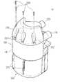
도 1은 청소기 본체로부터 분리된 상태의 본 발명의 일 실시예에 따른 사이클론 집진장치를 나타내는 사시도,1 is a perspective view showing a cyclone dust collector according to an embodiment of the present invention in a state separated from the cleaner body,
도 2은 본 발명의 일 실시예에 따른 사이클론 집진장치의 후방을 나타내는 사시도,Figure 2 is a perspective view showing the rear of the cyclone dust collector according to an embodiment of the present invention,
도 3은 본 발명의 일 실시예에 따른 사이클론 집진장치의 분해 사시도,3 is an exploded perspective view of a cyclone dust collector according to an embodiment of the present invention;
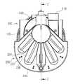
도 4는 본 발명의 일 실시예에 따른 사이클론 집진장치의 평면도,4 is a plan view of a cyclone dust collector according to an embodiment of the present invention,
도 5는 도 4에 표시된 Ⅴ-Ⅴ선을 따라 나타낸 단면도,5 is a cross-sectional view taken along the line VV of FIG. 4;
도 6은 도 3에 도시된 제1 커버의 다른 실시예를 나타낸 사시도,6 is a perspective view illustrating another embodiment of the first cover illustrated in FIG. 3;
도 7은 도 2에 도시된 먼지수거부 내측의 먼지유동억제리브를 보여주는 사시도이다.FIG. 7 is a perspective view illustrating a dust flow inhibiting rib inside the dust collecting unit illustrated in FIG. 2.
*도면 내 주요부분에 대한 부호설명** Description of Signs for Main Parts in Drawings *
100: 사이클론유닛110: 1차 사이클론부100: cyclone unit 110: primary cyclone portion
112: 차단판112a: 돌출관112: blocking
130: 2차 사이클론부200: 커버유닛130: secondary cyclone portion 200: cover unit
210: 제1 커버213,215: 씰링돌기210:
230: 제2 커버400: 가스켓230: second cover 400: gasket
Claims (13)
Translated fromKoreanPriority Applications (5)
| Application Number | Priority Date | Filing Date | Title |
|---|---|---|---|
| US12/284,546US7819933B2 (en) | 2008-05-14 | 2008-09-23 | Cyclone dust collector |
| GB0821446AGB2460102B (en) | 2008-05-14 | 2008-11-24 | Cyclonic dust collector |
| CA2645364ACA2645364C (en) | 2008-05-14 | 2008-11-27 | Cyclone dust collector |
| AU2008255167AAU2008255167B2 (en) | 2008-05-14 | 2008-12-08 | Cyclone dust collector |
| CN200810186924.XACN101612025B (en) | 2008-05-14 | 2008-12-10 | Cyclone dust collector |
Applications Claiming Priority (2)
| Application Number | Priority Date | Filing Date | Title |
|---|---|---|---|
| US12756308P | 2008-05-14 | 2008-05-14 | |
| US61/127,563 | 2008-05-14 |
Related Child Applications (1)
| Application Number | Title | Priority Date | Filing Date |
|---|---|---|---|
| KR1020140003215ADivisionKR101573732B1 (en) | 2008-05-14 | 2014-01-10 | Cyclone Dust Collecting Apparatus |
Publications (1)
| Publication Number | Publication Date |
|---|---|
| KR20090118794Atrue KR20090118794A (en) | 2009-11-18 |
Family
ID=41492056
Family Applications (2)
| Application Number | Title | Priority Date | Filing Date |
|---|---|---|---|
| KR1020080060945ACeasedKR20090118794A (en) | 2008-05-14 | 2008-06-26 | Cyclone dust collector |
| KR1020140003215AExpired - Fee RelatedKR101573732B1 (en) | 2008-05-14 | 2014-01-10 | Cyclone Dust Collecting Apparatus |
Family Applications After (1)
| Application Number | Title | Priority Date | Filing Date |
|---|---|---|---|
| KR1020140003215AExpired - Fee RelatedKR101573732B1 (en) | 2008-05-14 | 2014-01-10 | Cyclone Dust Collecting Apparatus |
Country Status (2)
| Country | Link |
|---|---|
| KR (2) | KR20090118794A (en) |
| CN (1) | CN101612025B (en) |
Cited By (3)
| Publication number | Priority date | Publication date | Assignee | Title |
|---|---|---|---|---|
| KR20140136591A (en)* | 2013-05-20 | 2014-12-01 | 주식회사 일렉파워전자 | Cyclone vaccum cleaner |
| CN110037615A (en)* | 2019-05-15 | 2019-07-23 | 宁波普净环保科技有限公司 | A kind of dust catcher and its working method with multistage cyclone separated structure |
| KR102069763B1 (en)* | 2019-02-18 | 2020-01-23 | (주)에이스일렉트로닉스 | Dust collector and vacuum cleaner having the same |
Families Citing this family (17)
| Publication number | Priority date | Publication date | Assignee | Title |
|---|---|---|---|---|
| CA2599303A1 (en) | 2007-08-29 | 2009-02-28 | Gbd Corp. | Surface cleaning apparatus |
| US10165912B2 (en) | 2006-12-15 | 2019-01-01 | Omachron Intellectual Property Inc. | Surface cleaning apparatus |
| US20140237764A1 (en) | 2013-02-28 | 2014-08-28 | G.B.D. Corp. | Cyclone such as for use in a surface cleaning apparatus |
| US9775484B2 (en) | 2013-03-01 | 2017-10-03 | Omachron Intellectual Property Inc. | Surface cleaning apparatus |
| FR3048172B1 (en)* | 2016-02-26 | 2018-06-22 | Seb Sa | ANTI-RECIRCULATION DEVICE |
| US9936846B2 (en) | 2016-04-25 | 2018-04-10 | Omachron Intellectual Property Inc. | Cyclone assembly for surface cleaning apparatus and a surface cleaning apparatus having same |
| US10149587B2 (en) | 2016-04-25 | 2018-12-11 | Omachron Intellectual Property Inc. | Cyclone assembly for surface cleaning apparatus and a surface cleaning apparatus having same |
| US10201260B2 (en) | 2016-04-25 | 2019-02-12 | Omachron Intellectual Property Inc. | Cyclone assembly for surface cleaning apparatus and a surface cleaning apparatus having same |
| US10537219B2 (en) | 2016-04-25 | 2020-01-21 | Omachron Intellectual Property Inc. | Cyclone assembly for surface cleaning apparatus and a surface cleaning apparatus having same |
| US10251521B2 (en) | 2016-04-25 | 2019-04-09 | Omachron Intellectual Property Inc. | Cyclone assembly for surface cleaning apparatus and a surface cleaning apparatus having same |
| US11930987B2 (en) | 2018-04-20 | 2024-03-19 | Omachron Intellectual Property Inc. | Surface cleaning apparatus |
| US10932634B2 (en) | 2018-05-30 | 2021-03-02 | Omachron Intellectual Property Inc. | Surface cleaning apparatus |
| US10827889B2 (en) | 2018-05-30 | 2020-11-10 | Omachron Intellectual Property Inc. | Surface cleaning apparatus |
| US10882059B2 (en) | 2018-09-21 | 2021-01-05 | Omachron Intellectual Property Inc. | Multi cyclone array for surface cleaning apparatus and a surface cleaning apparatus having same |
| KR20210138236A (en)* | 2020-05-12 | 2021-11-19 | 삼성전자주식회사 | Dust container and robot cleaner having the same |
| US11779178B2 (en) | 2021-08-05 | 2023-10-10 | Omachron Intellectual Property Inc. | Household appliance having an improved cyclone and a cyclone for same |
| US12075966B2 (en) | 2021-08-05 | 2024-09-03 | Omachron Intellectual Property Inc. | Household appliance having an improved cyclone and a cyclone for same |
Family Cites Families (7)
| Publication number | Priority date | Publication date | Assignee | Title |
|---|---|---|---|---|
| KR100398685B1 (en)* | 2000-11-27 | 2003-09-19 | 삼성광주전자 주식회사 | Cyclone dust-collecting apparatus for vacuum cleaner |
| KR100500829B1 (en)* | 2003-06-09 | 2005-07-12 | 삼성광주전자 주식회사 | Dust collecting apparatus of vacuum cleaner having two cyclones |
| KR100536504B1 (en)* | 2003-09-09 | 2005-12-14 | 삼성광주전자 주식회사 | A cyclone separating apparatus and vacumm cleaner equipped whth such a device |
| KR100554237B1 (en)* | 2003-09-08 | 2006-02-22 | 삼성광주전자 주식회사 | Cyclone Separator and Vacuum Cleaner With the Same |
| KR100595918B1 (en)* | 2004-02-11 | 2006-07-05 | 삼성광주전자 주식회사 | Cyclone dust collector |
| US7547336B2 (en)* | 2004-12-13 | 2009-06-16 | Bissell Homecare, Inc. | Vacuum cleaner with multiple cyclonic dirt separators and bottom discharge dirt cup |
| KR100607442B1 (en)* | 2005-03-29 | 2006-08-02 | 삼성광주전자 주식회사 | Multi cyclone dust collector and vacuum cleaner using the same |
- 2008
- 2008-06-26KRKR1020080060945Apatent/KR20090118794A/ennot_activeCeased
- 2008-12-10CNCN200810186924.XApatent/CN101612025B/ennot_activeExpired - Fee Related
- 2014
- 2014-01-10KRKR1020140003215Apatent/KR101573732B1/ennot_activeExpired - Fee Related
Cited By (3)
| Publication number | Priority date | Publication date | Assignee | Title |
|---|---|---|---|---|
| KR20140136591A (en)* | 2013-05-20 | 2014-12-01 | 주식회사 일렉파워전자 | Cyclone vaccum cleaner |
| KR102069763B1 (en)* | 2019-02-18 | 2020-01-23 | (주)에이스일렉트로닉스 | Dust collector and vacuum cleaner having the same |
| CN110037615A (en)* | 2019-05-15 | 2019-07-23 | 宁波普净环保科技有限公司 | A kind of dust catcher and its working method with multistage cyclone separated structure |
Also Published As
| Publication number | Publication date |
|---|---|
| KR20140012766A (en) | 2014-02-03 |
| KR101573732B1 (en) | 2015-12-04 |
| CN101612025B (en) | 2014-08-20 |
| CN101612025A (en) | 2009-12-30 |
Similar Documents
| Publication | Publication Date | Title |
|---|---|---|
| KR20090118794A (en) | Cyclone dust collector | |
| US7819933B2 (en) | Cyclone dust collector | |
| CN112043204B (en) | Air treatment component and cleaning equipment with same | |
| KR101003417B1 (en) | Dust collector of vacuum cleaner | |
| CN101909500B (en) | Hard surface vacuum | |
| KR100630952B1 (en) | Multi cyclone dust collector for vacuum cleaner and vacuum cleaner having same | |
| WO2020108492A1 (en) | Handheld cleaning apparatus | |
| US20090300871A1 (en) | Cyclone dust-collecting apparatus and vacuum cleaner having the same | |
| JP2006320713A (en) | Multi cyclone dust collector | |
| JP2006272322A (en) | Cyclone dust collector | |
| KR100778127B1 (en) | Vacuum cleaner | |
| KR101546839B1 (en) | Dust collector and vacuum cleaner | |
| KR100546629B1 (en) | Dust collector of vacuum cleaner | |
| WO2015180319A1 (en) | Cyclone separation device, dust collector, surface cleaning device, and cyclone separation method | |
| KR101262385B1 (en) | Multi cyclone dust collector in vacuum cleaner | |
| KR101566411B1 (en) | Wet type dust collecting apparatus for vacuum cleaner | |
| KR101473781B1 (en) | Cyclone Appratus for Collecting Dust | |
| KR20100093446A (en) | Dust separating apparatus of vacuum cleaner | |
| KR100789837B1 (en) | Cyclone dust collector | |
| CN111263606B (en) | filter box | |
| CN216293940U (en) | Dust separation module for cleaning machine and cleaning machine | |
| CN112237398B (en) | Electric vacuum cleaner | |
| KR102054419B1 (en) | Cyclone vaccum cleaner | |
| CN202778110U (en) | Dust separator | |
| RU2339290C2 (en) | Vacuum cleaner (versions) |
Legal Events
| Date | Code | Title | Description |
|---|---|---|---|
| PA0109 | Patent application | Patent event code:PA01091R01D Comment text:Patent Application Patent event date:20080626 | |
| PG1501 | Laying open of application | ||
| N231 | Notification of change of applicant | ||
| PN2301 | Change of applicant | Patent event date:20110324 Comment text:Notification of Change of Applicant Patent event code:PN23011R01D | |
| A201 | Request for examination | ||
| PA0201 | Request for examination | Patent event code:PA02012R01D Patent event date:20130626 Comment text:Request for Examination of Application Patent event code:PA02011R01I Patent event date:20080626 Comment text:Patent Application | |
| A302 | Request for accelerated examination | ||
| PA0302 | Request for accelerated examination | Patent event date:20131007 Patent event code:PA03022R01D Comment text:Request for Accelerated Examination Patent event date:20080626 Patent event code:PA03021R01I Comment text:Patent Application | |
| E902 | Notification of reason for refusal | ||
| PE0902 | Notice of grounds for rejection | Comment text:Notification of reason for refusal Patent event date:20131112 Patent event code:PE09021S01D | |
| A107 | Divisional application of patent | ||
| PA0107 | Divisional application | Comment text:Divisional Application of Patent Patent event date:20140110 Patent event code:PA01071R01D | |
| E902 | Notification of reason for refusal | ||
| PE0902 | Notice of grounds for rejection | Comment text:Notification of reason for refusal Patent event date:20140306 Patent event code:PE09021S01D | |
| E601 | Decision to refuse application | ||
| PE0601 | Decision on rejection of patent | Patent event date:20140521 Comment text:Decision to Refuse Application Patent event code:PE06012S01D Patent event date:20140306 Comment text:Notification of reason for refusal Patent event code:PE06011S01I Patent event date:20131112 Comment text:Notification of reason for refusal Patent event code:PE06011S01I | |
| J201 | Request for trial against refusal decision | ||
| PJ0201 | Trial against decision of rejection | Patent event date:20140527 Comment text:Request for Trial against Decision on Refusal Patent event code:PJ02012R01D Patent event date:20140521 Comment text:Decision to Refuse Application Patent event code:PJ02011S01I Appeal kind category:Appeal against decision to decline refusal Appeal identifier:2014101003163 Request date:20140527 | |
| J301 | Trial decision | Free format text:TRIAL DECISION FOR APPEAL AGAINST DECISION TO DECLINE REFUSAL REQUESTED 20140527 Effective date:20141023 Free format text:TRIAL NUMBER: 2014101003163; TRIAL DECISION FOR APPEAL AGAINST DECISION TO DECLINE REFUSAL REQUESTED 20140527 Effective date:20141023 | |
| PJ1301 | Trial decision | Patent event code:PJ13011S01D Patent event date:20141023 Comment text:Trial Decision on Objection to Decision on Refusal Appeal kind category:Appeal against decision to decline refusal Request date:20140527 Decision date:20141023 Appeal identifier:2014101003163 |