KR20090117813A - Dental Implants, Abutment Structures, and Dental Implants - Google Patents
Dental Implants, Abutment Structures, and Dental ImplantsDownload PDFInfo
- Publication number
- KR20090117813A KR20090117813AKR1020097019431AKR20097019431AKR20090117813AKR 20090117813 AKR20090117813 AKR 20090117813AKR 1020097019431 AKR1020097019431 AKR 1020097019431AKR 20097019431 AKR20097019431 AKR 20097019431AKR 20090117813 AKR20090117813 AKR 20090117813A
- Authority
- KR
- South Korea
- Prior art keywords
- abutment
- component
- tubular
- screw
- dental implant
- Prior art date
- Legal status (The legal status is an assumption and is not a legal conclusion. Google has not performed a legal analysis and makes no representation as to the accuracy of the status listed.)
- Withdrawn
Links
Images


Classifications
- A—HUMAN NECESSITIES
- A61—MEDICAL OR VETERINARY SCIENCE; HYGIENE
- A61C—DENTISTRY; APPARATUS OR METHODS FOR ORAL OR DENTAL HYGIENE
- A61C8/00—Means to be fixed to the jaw-bone for consolidating natural teeth or for fixing dental prostheses thereon; Dental implants; Implanting tools
- A—HUMAN NECESSITIES
- A61—MEDICAL OR VETERINARY SCIENCE; HYGIENE
- A61C—DENTISTRY; APPARATUS OR METHODS FOR ORAL OR DENTAL HYGIENE
- A61C8/00—Means to be fixed to the jaw-bone for consolidating natural teeth or for fixing dental prostheses thereon; Dental implants; Implanting tools
- A61C8/0048—Connecting the upper structure to the implant, e.g. bridging bars
- A61C8/005—Connecting devices for joining an upper structure with an implant member, e.g. spacers
- A61C8/0069—Connecting devices for joining an upper structure with an implant member, e.g. spacers tapered or conical connection
- A—HUMAN NECESSITIES
- A61—MEDICAL OR VETERINARY SCIENCE; HYGIENE
- A61C—DENTISTRY; APPARATUS OR METHODS FOR ORAL OR DENTAL HYGIENE
- A61C8/00—Means to be fixed to the jaw-bone for consolidating natural teeth or for fixing dental prostheses thereon; Dental implants; Implanting tools
- A61C8/0048—Connecting the upper structure to the implant, e.g. bridging bars
- A61C8/005—Connecting devices for joining an upper structure with an implant member, e.g. spacers
- A61C8/006—Connecting devices for joining an upper structure with an implant member, e.g. spacers with polygonal positional means, e.g. hexagonal or octagonal
Landscapes
- Health & Medical Sciences (AREA)
- Oral & Maxillofacial Surgery (AREA)
- Orthopedic Medicine & Surgery (AREA)
- Dentistry (AREA)
- Epidemiology (AREA)
- Life Sciences & Earth Sciences (AREA)
- Animal Behavior & Ethology (AREA)
- General Health & Medical Sciences (AREA)
- Public Health (AREA)
- Veterinary Medicine (AREA)
- Dental Prosthetics (AREA)
Abstract
Translated fromKoreanDescription
Translated fromKorean본 발명은 관상(coronal) 구성요소의 지지를 위한 치과용 임플란트에 관한 것으로서, 상기 임플란트는 상기 임플란트의 정점 뼈 접촉 부품을 형성하는 고정 부품과, 상기 임플란트의 관상 구성요소 지지 부품을 형성하는 지대치 부품과, 지대치 스크류를 포함하며, 상기 지대치 부품은 상기 치과용 임플란트의 조립 상태에서 상기 지대치 스크류에 의해 상기 고정 부품에 고정되도록 배치되는 것인 치과용 임플란트에 관한 것이다.The present invention relates to a dental implant for the support of a coronal component, said implant comprising a stationary component forming a vertex bone contact part of said implant and abutment component forming a tubular component support part of said implant And abutment screw, wherein the abutment component is disposed to be fixed to the fixed part by the abutment screw in an assembled state of the dental implant.
본 발명은 또한 관상 구성요소를 지지하도록 되어 있는 치과용 임플란트에서 사용하기 위한 지대치 구조에 관한 것으로서, 상기 지대치 구조는 상기 임플란트의 고정 부품에 의해 지지되도록 되어 있으며, 상기 지대치 구조는 적어도 지대치 부품 및 지대치 스크류를 포함하고, 상기 지대치 부품은 상기 지대치 스크류에 의해 상기 고정 부품에 고정되도록 되어 있는 것인 지대치 구조에 관한 것이다.The invention also relates to abutment structure for use in a dental implant adapted to support a tubular component, wherein the abutment structure is adapted to be supported by a stationary part of the implant, wherein the abutment structure is at least abutment part and abutment. And abutment parts, wherein the abutment component is adapted to be fixed to the fixed component by the abutment screw.
본 발명은 또한 치과용 임플란트의 이식 방법에 관한 것이다.The present invention also relates to a method for implanting a dental implant.
치과용 임플란트 시스템은 손상되거나 손실된 자연 치아를 대체하기 위해 광범위하게 사용된다. 이러한 치과용 임플란트 시스템에 있어서, 고정 부품은 보통 환자의 위턱 또는 아래턱의 뼈 조직에 이식되어 자연 치근을 대체한다. 이때, 하나 또는 수 개의 부품을 포함하는 지대치 구조가 고정부에 부착되어, 뼈 조직으로부터 부드러운 잇몸 조직을 통해 환자의 입 안쪽으로 돌출되는 보철 치아의 부품을 위한 코어를 형성할 수 있다. 보철물 또는 치관(crown)이 상기 지대치 구조 상에 최종적으로 자리할 수 있다.Dental implant systems are widely used to replace damaged or lost natural teeth. In such dental implant systems, the fixation component is usually implanted into the bone tissue of the upper or lower jaw of the patient to replace the natural root. At this time, the abutment structure including one or several parts may be attached to the fixing part to form a core for the part of the prosthetic tooth protruding from the bone tissue into the patient's mouth through the soft gum tissue. A prosthesis or crown may finally be placed on the abutment structure.
전술한 바와 같이, 지대치 구조가 하나의 부품으로 이루어지는 치과용 임플란트가 존재하며, 지대치 구조가 2개 이상의 부품으로 이루어지는 치과용 임플란트가 존재한다. 지대치 구조가 수 개의 부품을 포함하는 경우, 제1 부품은 고정 부품에 대해 배치되는 지대치 부품일 수 있다. 예컨대, 상기 지대치 부품의 일부는 상기 고정 부품의 보어에 부분적으로 삽입될 수 있다. 고정 부품에 삽입되는 이러한 지대치 부품 부분은, 예컨대 육각형 또는 토르스(torx) 프로파일로 이루어질 수 있다. 이때, 고정 부품은 바람직하게는 대응하는 프로파일로 이루어지며, 상기 지대치 부품은, 상기 프로파일로 이루어지는 지대치 부품 부분이 고정 부품에 일단 삽입되면 고정 부품에 대해 회전으로 잠길 수 있게 된다. 지대치 부품은 또한 어떠한 부분도 고정 부품 내에 삽입되지 않고 고정 부품에 대해 배치되는 슬리브일 수 있다. 이들 구조 중 어느 구조에 있어서, 이때 지대치 구조의 제2 부품은 지대치 부품과 고정 부품을 맞물림 상태로 존속시키거나 유지시키기 위해 사용될 수 있다. 이러한 유지 요소는 예컨대 스크류일 수 있다. 임플란트가 조립 상태에 있을 경우, 스크류는 지대치 부품과 고정 부품의 실질적인 종방향 연장부를 따라 지대치 부품과 고정 부품에 마련되는 보어에서 연장될 수 있다. 이러한 경우에 있어서, 고정 부품에서 연장되는 보어는 바람직하게는 스크류의 나사와 맞물리기 위한 나사산 형성부를 포함한다.As described above, there is a dental implant in which the abutment structure consists of one part, and there is a dental implant in which the abutment structure consists of two or more parts. If the abutment structure includes several parts, the first part may be abutment part disposed relative to the stationary part. For example, part of the abutment part may be partially inserted into the bore of the stationary part. This abutment part portion, which is inserted into the stationary part, may for example consist of a hexagonal or tors profile. At this time, the fixing part is preferably made of a corresponding profile, and the abutment part can be locked in rotation with respect to the fixing part once the abutment part part consisting of the profile is inserted into the fixing part. The abutment part can also be a sleeve disposed relative to the stationary part without any part inserted into the stationary part. In any of these structures, the second part of the abutment structure can then be used to maintain or maintain the abutment part and the stationary part in engagement. Such a retaining element may for example be a screw. When the implant is in the assembled state, the screw may extend in the bore provided in the abutment part and the stationary part along a substantial longitudinal extension of the abutment part and the stationary part. In this case, the bore extending from the fastening part preferably comprises a threaded portion for engaging the screw of the screw.
최종적인 보철물은 기능성 및 심미성 양자를 위해 환자의 나머지 치아와 자연스럽게 어울리도록 크기 및 구조가 결정되어야만 한다. 환자의 나머지 치아와 조화를 이루도록 최종적인 보철물의 크기 및 구조를 결정하기 위해, 지대치 구조는 이에 따라 크기가 결정되어야만 한다. 또한, 지대치 구조는 의도된 방식으로 치아형 보철물을 지지할 수 있어야 하기 때문에, 지대치 구조는 긴 형상을 갖는 것이 유리하며, 즉 자연 치아와 같이 높이에 비해 다소 작은 직경을 갖는 것이 유리하다. 이때, 지대치 부품의 벽 두께는 매우 작아질 수 있다. 이는 특히 2부품 지대치 구조와 관련될 수 있는데, 왜냐하면 이 경우에는 지대치 부품에 유지 요소를 위한 보어를 배치하는 것이 바람직하기 때문이다. 지대치 구조의 바람직한 높이를 감안하면, 제작 관점에서 달성하기가 곤란하고 비용이 많이 소요될 수 있다.The final prosthesis must be sized and structured to fit naturally with the rest of the patient's teeth for both functionality and aesthetics. In order to determine the size and structure of the final prosthesis to match the rest of the patient's teeth, the abutment structure must be sized accordingly. In addition, since the abutment structure must be able to support the dental prosthesis in the intended manner, it is advantageous for the abutment structure to have a long shape, i. At this time, the wall thickness of the abutment part can be very small. This may in particular be related to a two-part abutment structure, in which case it is desirable to place a bore for the retaining element in the abutment part. Given the desired height of the abutment structure, it can be difficult and costly to achieve from a manufacturing standpoint.
또한, 치과용 임플란트 및 치과용 임플란트의 지대치 구조는 힘을 받을 수 있게 되어 있으며, 지탱을 위한 강도를 가져야만 한다. 이러한 힘은 환자의 구강 내에 치과용 임플란트를 이식하는 동안에 그리고 또한 치과용 임플란트를 갖춘 환자가 씹을 때와 같이 사용하는 동안에 발생할 수 있다. 보철물을 지지하는 지대치 구조의 벽 두께가 지대치 구조의 높이에 비해 작은 경우, 지대치 구조의 강도는 요구되고/요구되거나 필요한 수준보다 낮아질 수 있다.In addition, the dental implant and the abutment structure of the dental implant are capable of receiving force and must have strength for support. This force can occur during implantation of a dental implant into the mouth of a patient and also during use, such as when a patient with a dental implant chews. If the wall thickness of the abutment structure supporting the prosthesis is small relative to the height of the abutment structure, the strength of the abutment structure may be required and / or lower than required.
따라서, 지대치 구조의 강도와 관련하여 전술한 문제 없이 환자의 구강 내에 보철물을 지지하기 위해 이에 맞게 치수가 설정될 수 있는 적어도 2개의 부품을 갖 춘 지대치 구조를 포함하는 것인 치과용 임플란트에 대한 요구가 존재한다.Thus, there is a need for a dental implant that includes abutment structure having at least two parts that can be dimensioned accordingly to support the prosthesis in the patient's mouth without the aforementioned problems with regard to the strength of the abutment structure. Is present.
따라서, 본 발명의 목적은 이러한 요구를 충족하는 지대치 구조를 치과용 임플란트에 마련하는 것이다.Accordingly, it is an object of the present invention to provide a dental implant with abutment structures that meet these needs.
본 발명의 목적은 독립 청구항 1, 2 및 3 중 임의의 청구항에 따른 치과용 임플란트를 이용하여 달성된다. 본 발명의 목적은 또한 독립 청구항 26, 27 및 28 중 임의의 청구항에 따른 지대치 구조를 이용하여 달성된다. 본 발명의 목적은 또한 청구항 50, 51 및 52 중 임의의 청구항에 따른 방법을 이용하여 달성된다.The object of the present invention is achieved using a dental implant according to any of the
"관상(coronal)"이라는 용어는 본 명세서에서 그리고 본 출원 전체에 걸쳐 언급되는 구성요소의 상부 단부(head end) 또는 하부 단부(tail end)를 향하는 방향을 지시하기 위해 사용된다. 예를 들면, 지대치가 고정부에 연결되어 있는 상황에서, 지대치의 관상 방향은, 고정부로부터 먼 쪽을 향하는 지대치의 부품을 향하는 방향이다. 마찬가지로, "정점(apical)"이라는 용어는 구성요소의 삽입 단부를 향하는 방향을 지시한다. 고정부에 연결되는 지대치에 대해서, 정점 방향은 고정부를 향하는 방향이다. 따라서, 정점 방향과 관상 방향은 반대 방향이다. 또한, "축방향"이라는 용어는 본 출원 전체에 걸쳐 관상 단부로부터 정점 단부까지 취한 방향 또는 반대로 취한 방향을 지시하기 위해 사용된다.The term "coronal" is used to indicate the direction towards the head end or the tail end of the components referred to herein and throughout this application. For example, in the situation where the preparation tooth is connected to the fixed part, the tubular direction of the preparation tooth is a direction toward the component of the preparation tooth facing away from the fixing part. Likewise, the term "apical" indicates the direction towards the insertion end of the component. With respect to the preparation tooth connected to the fixed part, the vertex direction is the direction toward the fixed part. Therefore, the vertex direction and the coronal direction are opposite directions. In addition, the term "axial direction" is used throughout this application to indicate the direction taken from the tubular end to the apex end or vice versa.
본 발명의 일 양태에 따르면, 시멘트로 유지되는 관상 구성요소를 지지하기 위한 치과용 임플란트가 마련되며, 상기 임플란트는 상기 임플란트의 정점 뼈 접촉 부품을 형성하는 고정 부품과, 상기 임플란트의 관상 구성요소 지지 부품을 형성하는 지대치 부품과, 지대치 스크류를 포함하고, 상기 지대치 부품은 상기 치과용 임플란트의 조립 상태에서 상기 지대치 스크류에 의해 상기 고정 부품에 고정되도록 배치되며, 상기 지대치 스크류의 관상 단부 부분은 조립 상태에서 상기 지대치 부품의 관상 단부 부분의 관상으로 배치된다.According to one aspect of the invention, there is provided a dental implant for supporting a tubular component retained with cement, the implant supporting a stationary component forming a vertex bone contact component of the implant, and the tubular component support of the implant. Abutment parts forming a part and abutment screws, the abutment parts being arranged to be fixed to the fixed part by the abutment screws in an assembled state of the dental implant, the tubular end portion of the abutment screw being assembled In the tubular end portion of the abutment component.
본 발명의 또 다른 양태에 따라, 치과용 임플란트가 마련되며, 상기 치과용 임플란트는 상기 임플란트의 정점 뼈 접촉 부품을 형성하는 고정 부품, 상기 임플란트의 관상 구성요소 지지 부품을 형성하는 지대치 부품, 및 대체로 원통형인 관상 부분을 포함하는 지대치 스크류를 포함하고, 상기 지대치 부품은 상기 치과용 임플란트의 조립 상태에서 상기 지대치 스크류에 의해 상기 고정 부품에 고정되도록 배치되며, 상기 지대치 스크류의 관상 단부 부분은 조립 상태에서 상기 지대치 부품의 관상 단부 부분의 관상으로 위치하도록 배치된다.According to another aspect of the invention, a dental implant is provided, the dental implant comprising a stationary part forming the apical bone contact part of the implant, abutment part forming the tubular component support part of the implant, and generally Abutment screw including a cylindrical tubular portion, the abutment component being arranged to be secured to the stationary component by the abutment screw in the assembled state of the dental implant, the tubular end portion of the abutment screw being in the assembled state The tubular end portion of the abutment component is arranged to be tubular.
본 발명의 또 다른 양태에 따라, 치과용 임플란트가 마련되며, 상기 치과용 임플란트는 상기 임플란트의 정점 뼈 접촉 부품을 형성하는 고정 부품, 상기 임플란트의 관상 구성요소 지지 부품을 형성하는 지대치 부품, 및 지대치 스크류를 포함하고, 상기 지대치 부품은 상기 치과용 임플란트의 조립 상태에서 상기 지대치 스크류에 의해 상기 고정 부품에 고정되도록 배치되며, 상기 지대치 스크류는 상기 지대치 스크류의 관상 단부 표면에 배치되는 구동 수단을 포함하고, 상기 외측 관상 단부 표면은 상기 지대치 스크류의 축방향에 실질적으로 수직하며, 상기 지대치 스크류의 관상 단부 부분은 상기 조립 상태에서 상기 지대치 부품의 관상 단부 부분의 관상으로 위치하도록 배치된다.According to another aspect of the invention, a dental implant is provided, the dental implant comprising a stationary component forming a vertex bone contact component of the implant, abutment component forming a tubular component support component of the implant, and abutment And abutment component is arranged to be secured to the fixed component by the abutment screw in an assembled state of the dental implant, the abutment screw including drive means disposed on the tubular end surface of the abutment screw; The outer coronal end surface is substantially perpendicular to the axial direction of the abutment screw, the tubular end portion of the abutment screw being arranged to be tubularly positioned in the tubular end portion of the abutment component in the assembled state.
본 발명의 기본적인 개념은, 이에 따라 임플란트가 조립되어 있을 때 지대치 스크류의 일부가 지대치 부품의 관상 단부 부분의 관상으로 연장되도록 하는 치과용 임플란트를 제공하는 것이다. 치과용 치관, 치과용 브릿지의 일부, 번아웃 실린더(burn-out cylinder), 힐링 캡(healing cap), 왁싱 슬리브(waxing sleeve), 또는 임프레션 픽업(impression pick-up)과 같은 관상 구성요소는 이에 따라 상기 치과용 임플란트에 장착될 때 지대치 스크류의 관상 부분과 접촉하고 이 관상 부분에 의해 적어도 부분적으로 지지된다. 관상 구성요소는 또한 지대치 부품에도 접촉하고 적어도 부분적으로 이 지대치 부품에 의해 지지되는 것이 바람직할 수 있다. 예를 들면, 지대치 스크류는 치과용 임플란트의 종축에 수직한 방향으로 관상 구성요소 상에 작용할 수 있는 힘 성분을 지탱하는 방식으로 관상 구성요소를 지지할 수 있다. 지대치 부품은 이때 관상 구성요소에 작용할 수 있는 회전력을 지탱하는 방식으로 관상 구성요소를 지지할 수 있다.The basic idea of the invention is thus to provide a dental implant such that when the implant is assembled a portion of the preparation screw extends into the tubular portion of the tubular end portion of the preparation component. Tubular components such as dental crowns, parts of dental bridges, burn-out cylinders, healing caps, waxing sleeves, or impression pick-ups It is thus in contact with and supported at least in part by the tubular portion of the abutment screw when mounted to the dental implant. The tubular component may also preferably be in contact with the abutment part and at least partially supported by the abutment part. For example, the abutment screw can support the tubular component in a manner that supports a force component that can act on the tubular component in a direction perpendicular to the longitudinal axis of the dental implant. The abutment component can then support the tubular component in a manner that supports the rotational force that can act on the tubular component.
지대치 스크류는 중실 단편으로 제작될 수 있다. 이로 인한 결과로서, 관상 구성요소를 지지하는 부품의 얇은 벽 두께와 관련된 전술한 문제는, 적어도 부분적으로 줄어들 수 있다. 이에 따라, 심지어 지대치 스크류의 직경이 그 높이에 비해 다소 작을 때에도, 지대치 스크류의 강도는 만족스러울 정도로 높을 수 있다. 따라서, 지대치 구조의 강도는 이식 및 관상 구성요소의 지지 양자 모두에 대해 만족스러울 정도로 높을 수 있다.The abutment screw can be made of solid pieces. As a result of this, the aforementioned problems associated with the thin wall thickness of the part supporting the tubular component can be at least partially reduced. Thus, even when the diameter of the abutment screw is somewhat smaller than its height, the strength of the abutment screw can be satisfactorily high. Thus, the strength of the abutment structure can be satisfactorily high for both implantation and support of the tubular component.
상기 지대치 스크류는 상기 지대치 스크류의 관상 단부 표면에 배치되는 구동 수단을 포함하는 것이 적절할 수 있으며, 상기 관상 단부 표면은 상기 지대치 스크류의 축방향에 실질적으로 수직하다.The abutment screw may suitably comprise drive means disposed on the tubular end surface of the abutment screw, the tubular end surface being substantially perpendicular to the axial direction of the abutment screw.
이는, 고정 부품에 대해 지대치 스크류를 조이고 풀기 위한 구동 수단을 배치하는 방법에 있어서 유리한 방식일 수 있다. 이때 관상 단부 표면은 바람직하게는 지대치 스크류의 외측 관상 단부 표면이다. 그러나, 지대치 스크류의 관상 부분에서 예컨대 내측 또는 외측 육각형 프로파일로서 구동 수단을 배치하는 것이 가능할 수 있다. 또한, 지대치 스크류의 정점 부분에는 나사산이 마련되어 치과용 임플란트가 조립되어 있을 때 고정 부품의 대응하는 부분에 나사식으로 맞물리는 것이 적절할 수 있다.This may be advantageous in the way of arranging the drive means for tightening and releasing the abutment screw relative to the stationary component. The tubular end surface is then preferably the outer tubular end surface of the abutment screw. However, it may be possible to arrange the drive means in the tubular portion of the abutment screw, for example as an inner or outer hexagonal profile. It may also be appropriate for a vertex portion of the abutment screw to be threaded to engage the corresponding portion of the fastening component when the dental implant is assembled.
바람직하게는, 상기 치과용 임플란트는 시멘트로 유지되는 관상 구성요소를 지지하도록 되어 있다.Preferably, the dental implant is adapted to support tubular components held in cement.
관상 구성요소는 상기 치과용 임플란트에 대해 시멘트로 유지될 수 있다. 그러나, 또한 지대치 스크류 및/또는 지대치 부품에 나사산을 배치하여 치과용 임플란트에 대해 치과용 구성요소를 나사식으로 유지하는 것도 가능할 수 있다.The tubular component may be retained in cement relative to the dental implant. However, it may also be possible to thread the dental abutment screw and / or the abutment component to retain the dental component relative to the dental implant.
바람직하게는, 상기 지대치 스크류는 실질적으로 원통형인 관상 부분을 포함한다.Preferably, the abutment screw comprises a substantially cylindrical tubular portion.
그러나, 또한 관상 부분에는 외측 육각형 프로파일 또는 임의의 다른 적절한 프로파일이 마련될 수 있다.However, the tubular portion may also be provided with an outer hexagonal profile or any other suitable profile.
바람직하게는, 상기 지대치 스크류의 상기 구동 수단은 적어도 하나의 노치를 포함한다.Preferably, said drive means of said abutment screw comprises at least one notch.
구동 수단에 있는 적어도 하나의 노치는 치과용 임플란트에 대해 지대치 스크류를 조이거나 제거할 수 있도록 하는 유리한 구조일 수 있다. 또한, 2개의 노치를 구동 수단에 마련하는 것이 적절할 수 있다. 이들 노치는 지대치 스크류의 관상 단부 표면에 배치될 수 있으며, 서로에 대해 수직일 수 있고 서로 교차할 수 있다. 이러한 구조는 치과용 임플란트의 고정 부품에 대한 지대치 스크류의 조임 및 제거에 있어서 사용자에게 훨씬 더 도움이 될 수 있다.At least one notch in the drive means may be of an advantageous construction that allows for tightening or removal of the abutment screw for the dental implant. It may also be appropriate to provide two notches in the drive means. These notches may be disposed on the tubular end surface of the abutment screw and may be perpendicular to each other and intersect with each other. This structure can be much more helpful to the user in tightening and removing the abutment screw to the stationary part of the dental implant.
바람직하게는, 상기 지대치 스크류의 상기 관상 단부 부분은 상기 치과용 임플란트의 관상 단부 부분을 형성한다.Preferably, the tubular end portion of the abutment screw forms a tubular end portion of the dental implant.
바람직하게는, 상기 지대치 부품의 관상으로 연장되는 상기 지대치 스크류의 상기 관상 단부 부분은 상기 관상 구성요소를 지지하도록 배치된다.Preferably, the tubular end portion of the abutment screw extending tubularly of the abutment component is arranged to support the tubular component.
이에 의해, 관상 구성요소는 지대치 스크류의 관상 부분에 의해 적어도 부분적으로 지지될 수 있다. 그러나, 치과용 임플란트에 조립되어 있을 때 관상 구성요소는 또한 지대치 부품과 접촉하고 부분적으로 지대치 부품에 의해 지지되는 것이 바람직할 수 있다. 예를 들면, 지대치 스크류는, 치과용 임플란트의 종축에 수직한 방향으로 관상 구성요소 상에 작용할 수 있는 힘 성분과, 지대치 부품에 의해 지탱될 수 있는 관상 구성요소 상에 작용하는 회전력을 지탱하는 방식으로 관상 구성요소를 지지할 수 있다. 이는, 필요한 하중을 지탱하도록 치과용 임플란트를 배치하고, 동시에 원하는 형상, 예컨대 치과용 임플란트의 직경이 그 높이에 비해 약간 작은 구조를 갖는 치과용 임플란트를 구성하도록 할 수 있는 가능성을 제공한다.Thereby, the tubular component can be at least partially supported by the tubular portion of the abutment screw. However, it may be desirable for the tubular component to be in contact with the abutment part and partially supported by the abutment part when assembled to a dental implant. For example, the abutment screw supports a force component that can act on the tubular component in a direction perpendicular to the longitudinal axis of the dental implant and a rotational force acting on the tubular component that can be supported by the abutment component. To support the tubular component. This offers the possibility of placing the dental implant to bear the necessary loads, while at the same time making it possible to construct a dental implant with a desired shape, for example a diameter of the dental implant slightly smaller than its height.
바람직하게는, 상기 지대치 부품의 적어도 일부는 상기 치과용 임플란트의 적어도 관상 방향으로 테이퍼진 원추 형상을 갖는다.Preferably, at least a portion of the abutment component has a conical shape that is tapered in at least the tubular direction of the dental implant.
바람직하게는, 상기 지대치 스크류의 적어도 일부는 상기 치과용 임플란트의 적어도 관상 방향으로 테이퍼진 원추 형상을 갖는다.Preferably, at least a portion of the abutment screw has a conical shape that is tapered in at least the tubular direction of the dental implant.
지대치 부품 및/또는 지대치 스크류의 테이퍼진 형상 또는 각진 형상은, 환자의 턱 뼈에서 치과용 임플란트의 위치 설정에 도움이 된다. 치과용 임플란트가 위치하게 되는 턱뼈의 형상은 다양한 환자마다 변할 수 있다. 따라서, 고정 부품이 위치하게 되는 턱뼈에 있는 보어 구멍은 때때로 기울어진 방향으로 제작되어야만 한다. 서로 나란하게 여러 개의 치과용 임플란트를 위치 설정하는 경우, 이때 치과용 임플란트에 관상 구성요소를 조립하려고 시도하는 과정에서 충돌이 있을 수 있다. 또한, 단지 하나의 치과용 임플란트를 이식하는 경우에 치과용 임플란트를 둘러싸는 기존의 치아와도 이러한 충돌이 일어날 수 있다. 지대치 부품 및/또는 지대치 스크류의 테이퍼진 형상 또는 각진 형상을 이용하여, 이러한 충돌을 적어도 부분적으로 줄일 수 있다. 따라서, 지대치 부품 및 지대치 스크류 중 어느 하나 또는 양자 모두의 테이퍼진 형상은 환자의 턱뼈에서 구멍을 뚫기 위한 공차를 증가시킨다. 상기 치과용 임플란트의 조립 상태에서 지대치 부품의 관상으로 연장되도록 되어 있는 부분에 있어서 지대치 스크류가 테이퍼져 있는 것이 바람직할 수 있다.The tapered or angular shape of the abutment component and / or the abutment screw assists in positioning the dental implant in the jaw bone of the patient. The shape of the jawbone where the dental implant is placed can vary from patient to patient. Therefore, the bore hole in the jawbone where the fixing part is to be placed must sometimes be made in an inclined direction. If multiple dental implants are positioned next to each other, there may be a conflict in the process of attempting to assemble the tubular component to the dental implant. In addition, such a collision may also occur with existing teeth surrounding the dental implant in the case of implantation of only one dental implant. Tapered or angular shapes of abutment parts and / or abutment screws can be used to at least partially reduce this collision. Thus, the tapered shape of either or both of the abutment component and the abutment screw increases the tolerance for drilling holes in the jawbone of the patient. It may be desirable for the abutment screw to be tapered at the portion intended to extend in the tubular form of the abutment component in the assembled state of the dental implant.
상기 지대치 부품에는 상기 지대치 부품의 축방향으로 연장되는 내측 보어가 마련되는 것이 바람직하며, 상기 보어에는 테이퍼진 부분이 마련되고, 이 부분은 상기 지대치 부품의 정점 방향으로 테이퍼지게 된다.The abutment component is preferably provided with an inner bore extending in the axial direction of the abutment component, the bore is provided with a tapered portion, which is tapered in the apex direction of the abutment component.
상기 지대치 부품에서의 내측 보어는 지대치 부품을 통한 지대치 스크류의 삽입에 있어서 유리하다. 상기 지대치 부품의 내측 보어에 테이퍼진 부분이 마련되어 있다면 더 유리하며, 지대치 스크류에는 지대치 부품의 테이퍼진 부분에 접합되도록 되어 있는 대응부가 마련된다. 이러한 테이퍼진 부분 또는 쇼울더(shoulder)는, 이제 상기 치과용 임플란트의 조립 상태에서, 즉 지대치 스크류가 상기 보어를 통해 연장되고 고정 부품과 나사식으로 맞물리도록 배치되어 있을 때 지대치 부품의 축방향 이동을 방지할 수 있다.The inner bore in the abutment part is advantageous for the insertion of the abutment screw through the abutment part. It is more advantageous if the tapered portion is provided in the inner bore of the abutment component, and the abutment screw is provided with a corresponding portion adapted to be joined to the tapered portion of the abutment component. This tapered part or shoulder now supports the axial movement of the abutment part in the assembled state of the dental implant, ie when the abutment screw is arranged to extend through the bore and threadedly engage the stationary part. You can prevent it.
바람직하게는, 상기 지대치 스크류는 상기 치과용 임플란트의 상기 조립 상태에서 상기 지대치 부품 및 상기 고정 부품에 각각 배치된 보어에서 연장되도록 배치된다.Preferably, the abutment screw is arranged to extend in the bore disposed respectively in the abutment part and the stationary part in the assembled state of the dental implant.
이는, 의도한 방식으로 조립할 수 있도록 치과용 임플란트를 배치하는 방식에 있어서 유리한 방식이다.This is an advantageous way of placing the dental implant so that it can be assembled in the intended way.
상기 지대치 부품 및/또는 상기 지대치 스크류에는 상기 관상 구성요소와 맞물리도록 배치되는 스냅 피팅(snap fitting)이 마련되는 것이 바람직할 수 있다.It may be desirable for the abutment component and / or the abutment screw to be provided with a snap fitting arranged to engage the tubular component.
지대치 부품 및/또는 지대치 스크류에 배치되는 스냅 피팅은, 치과용 임플란트에 대해 관상 구성요소를 고정하는 방식에 있어서 유리한 방식일 수 있다. 스냅 피팅은 예컨대 지대치 부품에서의 홈을 포함할 수 있다. 이때 관상 구성요소에는 대응부가 마련될 수 있으며, 이 대응부는 치과용 임플란트에 대해 관상 구성요소를 장착할 때 홈 내부에 스냅식으로 채결될 수 있다.Snap fittings disposed on the abutment component and / or the abutment screw can be advantageous in the manner of securing the tubular component relative to the dental implant. The snap fitting may for example comprise a groove in the abutment part. The tubular component may be provided with a counterpart, which may be snapped into the groove when the tubular component is mounted to the dental implant.
상기 관상 구성요소를 지지하도록 의도되는 상기 지대치 부품의 적어도 일부에는 상기 지대치 부품의 유지 능력을 향상시키기 위한 수단이 마련되는 것이 바람직할 수 있다.It may be desirable for at least some of the abutment parts intended to support the tubular component to be provided with means for improving the holding capacity of the abutment parts.
향상된 유지 능력 또는 마찰 능력은, 관상 구성요소가 의도치 않게 치과용 임플란트로부터 분리되지 못하도록 함에 있어서 유리할 수 있다. 이러한 향상된 유지 능력은, 예컨대 블래스트 처리된 표면, 에칭 처리된 표면, 널링 처리된 표면 또는 홈이 형성된 표면을 지대치 부품에 제공함으로써 마련될 수 있다.Improved retention or frictional capacity may be advantageous in preventing the tubular component from being inadvertently detached from the dental implant. This improved retention capability can be provided, for example, by providing the abutment part with a blasted surface, an etched surface, a knurled surface or a grooved surface.
바람직하게는, 상기 지대치 부품에는 부착된 관상 구성요소가 회전하지 못하도록 하기 위한 하나 이상의 회전 정지부가 마련된다.Preferably, the abutment part is provided with one or more rotation stops to prevent the attached tubular component from rotating.
일단 관상 구성요소가 원하는 배향으로 치과용 임플란트에 부착되면, 관상 구성요소의 회전 가능성을 제한하는 것이 유리하다. 회전 정지부는 지대치 부품의 상부 또는 관상 부분에 리세스 또는 컷아웃으로서 배치될 수 있다. 관상 구성요소의 내측부 상에 마련되는 돌출부는 이때 조립 상태에서 리세스 내부에 끼워질 수 있으며, 이에 따라 치과용 임플란트에 대해 관상 구성요소가 회전할 가능성을 없애거나 제한한다. 지대치 부품의 관상 부분에서 회전 정지부로서 기능하도록 의도된 여러 개의 컷아웃 또는 리세스를 배치하는 것도 또한 가능하다.Once the tubular component is attached to the dental implant in the desired orientation, it is advantageous to limit the possibility of rotation of the tubular component. The rotation stop can be disposed as a recess or cutout in the upper or tubular portion of the abutment part. Projections provided on the inner side of the tubular component can then fit inside the recess in the assembled state, thereby eliminating or limiting the possibility of the tubular component rotating relative to the dental implant. It is also possible to arrange several cutouts or recesses intended to function as rotation stops in the tubular part of the abutment part.
바람직하게는, 상기 관상 구성요소를 지지하도록 의도된, 상기 지대치 부품의 외측 둘레의 적어도 일부는 비원형 외형을 갖는다.Preferably, at least a portion of the outer perimeter of the abutment component, intended to support the tubular component, has a non-circular shape.
지대치 부품의 비원형 외형의 적어도 일부는, 치과용 임플란트에 대해 관상 구성요소의 회전 가능성을 없애거나 또는 적어도 제한함에 있어서 유리한 방식이다. 비원형 외형은, 예컨대 타원형, 정사각형, 직사각형 또는 삼각형일 수 있다. 바람직하게는, 관상 구성요소의 내측면의 일부, 즉 관상 구성요소가 치과용 임플란트 상에 장착될 때 지대치 부품과 접촉하는 부분은 대응하는 형상을 갖는다.At least a portion of the non-circular contour of the abutment part is advantageous in eliminating or at least limiting the possibility of rotation of the tubular component relative to the dental implant. Non-circular contours can be, for example, oval, square, rectangular or triangular. Preferably, a portion of the inner side of the tubular component, ie the portion that contacts the abutment component when the tubular component is mounted on the dental implant, has a corresponding shape.
바람직하게는, 상기 치과용 임플란트의 상기 조립 상태에서 상기 지대치 부품의 관상 단부 부분의 관상으로 연장되는 상기 지대치 스크류의 상기 관상 단부 부분은, 축방향으로 1 내지 7 mm의 길이를 갖는다.Preferably, the tubular end portion of the abutment screw extending tubularly of the tubular end portion of the abutment component in the assembled state of the dental implant has a length of 1 to 7 mm in the axial direction.
바람직하게는, 사용 중에 상기 치과용 임플란트에 부착된 관상 구성요소와 접촉할 수 있는 상기 지대치 부품의 일부는, 축방향으로 1 내지 5 mm의 길이를 갖는다.Preferably, the portion of the abutment part that can contact the tubular component attached to the dental implant during use has a length of 1 to 5 mm in the axial direction.
바람직하게는, 사용 중에 상기 치과용 임플란트에 부착된 관상 구성요소와 접촉할 수 있는 상기 지대치 부품의 일부는 축방향으로 2 내지 2.5 mm의 길이를 갖는다.Preferably, the portion of the abutment part that can contact the tubular component attached to the dental implant during use has a length of 2 to 2.5 mm in the axial direction.
바람직하게는, 사용 중에 관상 구성요소와 접촉하고 이 관상 구성요소를 지지할 수 있는 지대치 스크류의 일부 또는 지대치 부품의 일부의 전체 길이는 축방향으로 3 내지 8 mm이다.Preferably, the total length of the portion of the abutment screw or the portion of the abutment component that is in contact with and can support the tubular component during use is 3 to 8 mm in the axial direction.
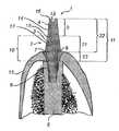
조립 상태에서 치과용 임플란트의 고정 부품의 관상으로 위치하는 치과용 임플란트의 지대치 구조 부분은, 3개의 부분으로 간주될 수 있다. 제1 부분은 지대치 부품 조직 연장 부분이다. 이 부분은, 지대치 부품 중 사용하는 동안 고정 부품에 가장 근접하게 위치하는 부분이다. 이 부분의 목적은, 환자의 조직 또는 잇몸에 대해 오버브릿지(overbridge)하는 것이다. 지대치 부품 조직 연장 부분은, 환자의 잇몸의 두께에 따라 0.5 내지 5 mm의 축방향 높이를 갖는다. 제2 부분은 지대치 부품 치관 맞물림 부분이라고 불리는 부분이다. 이 부분은 지대치 부품의 일부로서, 관상 구성요소를 임플란트에 부착할 때 관상 구성요소와 접촉하고 이 관상 구성요소를 지지할 수 있다. 관상 구성요소는 치관일 수 있지만, 또한 예컨대 왁싱 슬리브, 번아웃 실린더, 치과용 브릿지의 일부, 임프레션 픽업, 또는 임의의 다른 관상 구성요소일 수 있다. 이 부분의 높이는 치과용 임플란트의 구조에 따라 1 내지 5 mm 사이에서 변경될 수 있다. 지대치 스크류가 사용 중에 지대치 구조에 작용하는 힘의 대부분을 지탱하도록 지대치 구조를 구성하는 경우, 지대치 부품 치관 맞물림 부분은 축방향으로 1 내지 2 mm일 수 있다. 그러나, 또 다른 구조에 있어서, 지대치 부품은 지대치 구조에 작용하는 힘 중 더 많은 비율을 지탱할 수 있으며, 지대치 부품 치관 맞물림 부의 길이는 이때 2 내지 5 mm일 수 있다. 지대치 부품 치관 맞물림 부분의 높이는 2 내지 2.5 mm인 것이 또한 바람직할 수 있다. 이러한 높이는, 사용 중에 관상 구성요소에 인가될 수 있는 힘의 일부, 즉 주로 치과용 임플란트 상에 인가되는 회전력을 지탱하기에 적합할 수 있다. 지대치 부품에서 회전 정지부를 제공할 수 있도록 크기를 결정하는 것이 또한 적절할 수 있다. 고정 부품의 관상으로 연장되는 지대치 구조의 제3 부분은, 지대치 스크류의 관상 단부 부분이다. 지대치 스크류는 사용 중에 바람직하게는 지대치 부품을 관통하는 보어에서 고정 부품으로부터 연장되며, 지대치 부품의 관상 단부 부품의 관상으로 연장되는 관상 단부 부분을 갖는다. 이러한 관상 단부 부분은 또한 지대치 스크류 치관 맞물림 부분이라고 불릴 수도 있다. 지대치 스크류 치관 맞물림 부분의 길이는 또한 치과용 임플란트의 구조에 따라, 예컨대 치과용 임플란트를 삽입하려고 하는 환자의 턱뼈에서의 위치에 따라 변할 수 있다. 지대치 스크류 치관 맞물림 부분의 길이는 이에 따라 1 내지 7 mm 사이에서 변할 수 있다. 지대치 스크류 치관 맞물림 부분의 길이는 또한 지대치 부품 치관 맞물림 부분의 길이에 따라 변할 수 있다. 이에 따라, 지대치 부품 치관 맞물림 부분의 길이가 1 내지 2 mm 사이에서 변하는 구조에 있어서 지대치 스크류 치관 맞물림 부분의 길이는 2 내지 7 mm 사이에서 변하는 것이 바람직할 수 있다. 또한, 지대치 부품 치관 맞물림 부분이 2 내지 5 mm 사이에서 변하는 구조에 있어서 지대치 스크류 치관 맞물림 부분의 길이는 1 내지 6 mm 사이에서 변하는 것이 바람직할 수 있다. 지대치 부품 치관 맞물림 부분이 약 2 내지 2.5 mm인 구조에 있어서, 지대치 스크류 치관 맞물림 부분의 길이는 1 내지 6 mm 사이에서 변할 수 있다.The abutment structure portion of the dental implant positioned in the tubular position of the stationary part of the dental implant in the assembled state can be considered three parts. The first part is the abutment part tissue extension part. This part is the part of the abutment part closest to the stationary part during use. The purpose of this section is to overbridge the tissue or gums of the patient. The abutment component tissue extending portion has an axial height of 0.5 to 5 mm, depending on the thickness of the patient's gums. The second part is a part called the abutment part crown engaging part. This part is part of the abutment part and can contact and support the tubular component when attaching the tubular component to the implant. The tubular component may be a crown, but may also be, for example, a waxing sleeve, burnout cylinder, part of a dental bridge, impression pickup, or any other tubular component. The height of this part can vary between 1 and 5 mm depending on the structure of the dental implant. When the abutment screw is configured such that the abutment screw bears most of the force acting on the abutment structure during use, the abutment component crown engagement portion can be 1 to 2 mm in the axial direction. However, in another structure, the abutment component can support a greater proportion of the force acting on the abutment structure, and the length of the abutment component crown engagement portion can then be 2 to 5 mm. It may also be desirable for the abutment component crown engagement portion to have a height of 2 to 2.5 mm. This height may be suitable for supporting a portion of the force that may be applied to the tubular component during use, ie a rotational force applied primarily on the dental implant. It may also be appropriate to size to provide a rotational stop in the abutment part. The third portion of the abutment structure extending tubularly of the fixed part is the tubular end portion of the abutment screw. The abutment screw preferably extends from the stationary part in the bore through the abutment part during use and has a tubular end part extending into the tubular end part of the tubular end part of the abutment part. This tubular end portion may also be called abutment screw crown engagement portion. The length of the abutment screw crown engagement portion may also vary depending on the structure of the dental implant, such as its position in the jawbone of the patient attempting to insert the dental implant. The length of the abutment screw crown engagement portion may thus vary between 1 and 7 mm. The length of the abutment screw crown engagement portion may also vary depending on the length of the abutment component crown engagement portion. Accordingly, in a structure in which the length of the abutment component crown engagement portion varies between 1 and 2 mm, it may be desirable for the length of the abutment screw crown engagement portion to vary between 2 and 7 mm. Further, in a structure in which the abutment component crown engagement portion varies between 2 and 5 mm, it may be desirable for the length of the abutment screw crown engagement portion to vary between 1 and 6 mm. In structures where the abutment component crown engagement portion is about 2 to 2.5 mm, the length of the abutment screw crown engagement portion may vary between 1 and 6 mm.
또한, 사용 중에 관상 구성요소와 접촉할 수 있는 지대치 스크류의 일부 및 지대치 부품의 일부, 즉 지대치 부품 치관 맞물림 부분 및 지대치 스크류 치관 맞물림 부분의 전체 길이는 3 내지 8 mm인 것이 바람직할 수 있다. 다시 말하면, 임플란트를 이식할 때 지대치 구조가 환자의 잇몸의 관상으로 연장될 수 있는 전체 높이는 3 내지 8 mm이다. 이는 관상 구성요소를 지지하기에 적절할 수 있다.It may also be desirable for the total length of the portion of the abutment screw and the portion of the abutment component, ie the abutment part crown engagement portion and the abutment screw crown engagement portion, which may be in contact with the tubular component during use, to be 3 to 8 mm. In other words, the total height at which the abutment structure can extend into the coronary of the patient's gums when implanting is 3 to 8 mm. This may be appropriate to support the tubular component.
바람직하게는 상기 지대치 스크류의 상기 관상 단부 부분은 상기 치과용 임플란트의 상기 조립 상태에서 상기 지대치 부품의 상기 관상 단부 부분의 관상으로 적어도 1 mm 연장되도록 배치된다.Preferably the tubular end portion of the abutment screw is arranged to extend at least 1 mm into the tubular portion of the tubular end portion of the abutment component in the assembled state of the dental implant.
1 mm는 상기 지대치 스크류의 관상 단부 부분이 관상 구성요소를 지지할 수 있도록 하는 최소 요구 높이일 수 있다. 또한, 지대치 스크류는, 조립 상태에서 지대치 스크류의 관상 단부 부분이 지대치 부품의 관상 단부의 관상으로 7 mm까지 연장되도록 위치하게 되어 있을 수 있다.1 mm may be the minimum required height that allows the tubular end portion of the abutment screw to support the tubular component. In addition, the abutment screw may be positioned such that, in the assembled state, the tubular end portion of the abutment screw extends to 7 mm into the tubular end of the abutment component.
상기 치과용 임플란트의 조립 상태에서 고정 부품의 관상으로 위치하는 상기 지대치 부품의 일부의 길이는, 바람직하게는 적어도 1.5 mm이다. 즉, 지대치 부품 조직 연장 부분의 길이는 적어도 0.5 mm이며, 지대치 부품 치관 맞물림 부분의 길이는 적어도 1 mm이다. 그러나, 또한 치과용 임플란트 상에 가해지는 힘을 지탱하고 지대치 부품에서 회전 정지부의 배치가 용이하도록, 지대치 부품 치관 맞물림 부분은 적어도 2 mm인 것이 더욱 바람직할 수 있다. 치과용 임플란트의 조립 상태에서 고정 부품의 관상으로 위치하는 상기 지대치 부품의 일부의 길이는 이때 바람직하게는 적어도 2.5 mm일 수 있다. 상기 지대치 스크류의 길이는, 부분적으로, 상기 치과용 임플란트가 조립되어 있을 때 상기 고정 부품에 위치하게 되는 상기 지대치 스크류의 일부의 길이에 따라 좌우된다. 바람직하게는, 상기 치과용 임플란트의 조립 상태에서 상기 고정 부품의 관상으로 위치하는 지대치 스크류의 일부의 길이는 3.5 내지 13 mm이다. 바람직하게는, 지대치 스크류는 지대치 부품의 관상 단부 부분의 관상으로 1 mm 이상 7 mm 이하로 연장된다. 지대치 부품 치관 맞물림 부분의 길이가 2 내지 2.5 mm일 때, 지대치 스크류는 지대치 부품의 관상 단부 부분의 관상으로 1 mm 이상 6 mm 이하로 연장되는 것이 바람직할 수 있다.The length of a part of the abutment part, which is positioned in the tubular shape of the fixed part in the assembled state of the dental implant, is preferably at least 1.5 mm. That is, the length of the abutment component tissue extending portion is at least 0.5 mm, and the length of the abutment component crown engaging portion is at least 1 mm. However, it may be more desirable for the abutment part crown engagement portion to be at least 2 mm to support the force exerted on the dental implant and to facilitate placement of the rotational stop in the abutment part. The length of the portion of the abutment part which is located in the tubular position of the stationary part in the assembled state of the dental implant can then preferably be at least 2.5 mm. The length of the abutment screw depends, in part, on the length of the portion of the abutment screw that will be placed on the stationary component when the dental implant is assembled. Preferably, the length of the portion of the abutment screw positioned in the tubular position of the fastening part in the assembled state of the dental implant is 3.5 to 13 mm. Preferably, the abutment screw extends 1 mm or more and 7 mm or less in the tubular shape of the tubular end portion of the abutment part. When the abutment component crown engagement portion is 2 to 2.5 mm in length, it may be desirable for the abutment screw to extend from 1 mm to 6 mm in the tubular shape of the tubular end portion of the abutment component.
상기 치과용 임플란트의 조립 상태에서 상기 고정 부품의 관상으로 위치하는 지대치 부품의 일부는 적어도 1.5 mm인 것이 바람직하며, 즉 0.5 mm는 소위 지대치 부품 조직 연장 부분이고 1 mm는 소위 지대치 부품 치관 맞물림 부분이다. 상기 치과용 임플란트의 조립 상태에서 상기 고정 부품의 관상으로 위치하는 상기 지대치 스크류의 일부의 길이는 바람직하게는 13 mm 이하이다. 최대 길이인 경우에 있어서, 지대치 스크류 중 5 mm는 지대치 부품의 조직 연장 부분을 통해 연장되며, 8 mm는 지대치 부품의 조직 연장 부분의 관상으로 연장된다. 그러나, 상기 치과용 임플란트의 조립 상태에서 상기 고정 부품의 관상으로 위치하는 지대치 부품의 일부는 적어도 3 mm인 것이 훨씬 더 바람직할 수 있는데, 예컨대 1 mm는 지대치 부품 조직 연장 부분이고 적어도 2 mm는 지대치 부품 치관 맞물림 부분이다.Preferably, the part of the abutment component that is positioned in the tubular position of the fixation part in the assembled state of the dental implant is at least 1.5 mm, i. . The length of a portion of the abutment screw, which is positioned in the tubular shape of the fixed part in the assembled state of the dental implant, is preferably 13 mm or less. In the maximum length, 5 mm of the abutment screw extends through the tissue extending portion of the abutment component and 8 mm extends tubularly of the tissue extending portion of the abutment component. However, in the assembly of the dental implant it may be even more preferred that some of the abutment parts which are located in the tubular position of the fixation part are at least 3 mm, for example 1 mm is the abutment part tissue extension and at least 2 mm is the abutment. Component crown engagement.
치과용 임플란트가 조립되어 있을 때, 지대치 스크류는 지대치 부품의 관상 단부의 관상으로 그 길이의 일부가 연장될 수 있다. 지대치 스크류의 또 다른 일부는 지대치 부품에 마련되는 보어 내에서 연장될 수 있으며, 지대치 스크류의 제3 부분은 고정 부품과 맞물릴 수 있다. 지대치 부품의 일부는 조립 상태에서 고정부에 위치할 수 있다. 따라서, 지대치 부품에서 보어 내에 위치하는 지대치 스크류의 일부는 또한 고정부에 위치하게 된다.When the dental implant is assembled, the abutment screw can extend a portion of its length into the tubular end of the tubular end of the abutment component. Another portion of the abutment screw may extend within the bore provided in the abutment component and the third portion of the abutment screw may engage the stationary component. Some of the abutment parts may be located in the fixture in the assembled state. Thus, part of the abutment screw located in the bore in the abutment part is also located in the fixture.
바람직하게는, 상기 지대치 부품의 축방향으로 연장되는 상기 보어의 직경은 1.5 내지 5 mm이다. 상기 지대치 부품의 축방향으로 연장되는 상기 보어의 직경은 2 내지 4 mm인 것이 훨씬 더 바람직할 수 있다.Preferably, the diameter of the bore extending in the axial direction of the abutment component is 1.5 to 5 mm. It may be even more preferred that the diameter of the bore extending in the axial direction of the abutment part is 2 to 4 mm.
특정 치과용 임플란트에 있어서, 예컨대 심미적 동기를 위한 경우에는, 다소 작은 직경을 갖도록 요구될 수 있다. 이때, 지대치 부품에서 연장되는 보어의 직경이 전술한 범위 내에서 유지될 수 있다면 유리할 수 있다. 지대치 스크류의 직경은 지대치 부품 내의 보어의 직경에 대응하는 직경으로 제작될 수 있으며, 즉 1.5 내지 5 mm, 보다 바람직하게는 2 내지 4 mm이다.In certain dental implants, for example for aesthetic motives, it may be required to have a rather small diameter. At this time, it may be advantageous if the diameter of the bore extending from the abutment part can be maintained within the above-mentioned range. The diameter of the abutment screw can be made to a diameter corresponding to the diameter of the bore in the abutment part, ie 1.5 to 5 mm, more preferably 2 to 4 mm.
지대치 스크류의 관상 단부 부분의 직경은 1.5 내지 5 mm일 수 있다.The diameter of the tubular end portion of the abutment screw can be 1.5 to 5 mm.
지대치 부품의 관상 단부 부분의 직경은 2 내지 5 mm일 수 있다.The diameter of the tubular end portion of the abutment part can be 2 to 5 mm.
지대치 부품의 관상 단부에서 지대치 부품의 벽 두께는 0.2 내지 1.5 mm일 수 있다.The wall thickness of the abutment part at the tubular end of the abutment part can be 0.2 to 1.5 mm.
본 발명의 목적을 달성하기 위해, 즉 다소 긴 구조를 가지며 동시에 인가되는 힘에 견딜 수 있는 치과용 임플란트를 얻기 위해, 전술한 비율은 유리할 수 있다.In order to achieve the object of the present invention, ie to obtain a dental implant having a rather long structure and capable of withstanding the forces applied at the same time, the above ratios may be advantageous.
전술한 바와 같은 치과용 임플란트는 바람직하게는 환자의 구강에서 관상 구성요소를 지지하기 위해 사용된다.Dental implants as described above are preferably used to support the coronal components in the oral cavity of the patient.
본 발명의 또 다른 양태에 따르면, 치과용 임플란트에서 사용하기 위한 지대치 구조가 마련되며, 상기 지대치 구조는 시멘트로 유지되는 관상 구성요소를 지지하도록 되어 있고, 상기 지대치 구조는 상기 임플란트의 고정 부품에 의해 지지되도록 되어 있으며, 상기 지대치 구조는 적어도 지대치 부품 및 지대치 스크류를 포함하고, 상기 지대치 부품은 상기 지대치 스크류에 의해 상기 고정 부품에 고정되도록 되어 있으며, 상기 지대치 부품이 상기 지대치 스크류에 의해 상기 고정 부품에 고정될 때 상기 지대치 스크류의 관상 단부 부분이 상기 지대치 부품의 관상 단부 부분의 관상으로 위치하도록 상기 지대치 부품은 축방향 연장부를 갖는다.According to another aspect of the present invention, there is provided abutment structure for use in a dental implant, the abutment structure adapted to support a tubular component held in cement, the abutment structure being secured by a stationary part of the implant. Wherein the abutment structure comprises at least abutment component and abutment screw, the abutment component being secured to the fixed component by the abutment screw, wherein the abutment component is secured to the fixed component by the abutment screw. The abutment component has an axial extension such that when secured the tubular end portion of the abutment screw is positioned tubularly of the tubular end portion of the abutment component.
본 발명의 또 다른 양태에 따르면, 치과용 임플란트에서 사용하기 위한 지대치 구조가 마련되며, 상기 지대치 구조는 상기 임플란트의 고정 부품에 의해 지지되도록 되어 있고, 상기 지대치 구조는 적어도 지대치 부품 및 지대치 스크류를 포함하며, 상기 지대치 부품은 상기 지대치 스크류에 의해 상기 고정 부품에 고정되도록 되어 있고, 상기 지대치 스크류는 대체로 원통형인 관상 부분을 포함하며, 상기 지대치 부품이 상기 지대치 스크류에 의해 상기 고정 부품에 고정될 때 상기 지대치 스크류의 관상 단부 부분이 상기 지대치 부품의 관상 단부 부분의 관상으로 위치하도록 상기 지대치 부품은 축방향 연장부를 갖는다.According to another aspect of the invention, there is provided abutment structure for use in a dental implant, the abutment structure being adapted to be supported by a stationary part of the implant, wherein the abutment structure comprises at least abutment part and abutment screw. Wherein the abutment component is adapted to be secured to the stationary component by the abutment screw, the abutment screw comprising a generally cylindrical tubular portion, when the abutment component is secured to the stationary component by the abutment screw. The abutment component has an axial extension such that the tubular end portion of the abutment screw is positioned tubularly of the tubular end portion of the abutment component.
본 발명의 또 다른 양태에 따르면, 치과용 임플란트에서 사용하기 위한 지대치 구조가 마련되며, 상기 지대치 구조는 상기 임플란트의 고정 부품에 의해 지지되도록 되어 있고, 상기 지대치 구조는 적어도 지대치 부품 및 지대치 스크류를 포함하며, 상기 지대치 부품은 상기 지대치 스크류에 의해 상기 고정 부품에 고정되도록 되어 있고, 상기 지대치 스크류는 상기 지대치 스크류의 관상 단부 표면에 배치되는 구동 수단을 포함하며, 상기 지대치 스크류의 상기 관상 단부 표면은 상기 지대치 스크류의 축방향에 실질적으로 수직하고, 상기 지대치 부품이 상기 지대치 스크류에 의해 상기 고정 부품에 고정될 때 상기 지대치 스크류의 관상 단부 부분이 상기 지대치 부품의 관상 단부 부분의 관상으로 위치하도록 상기 지대치 부품은 축방향 연장부를 갖는다.According to another aspect of the invention, there is provided abutment structure for use in a dental implant, the abutment structure being adapted to be supported by a stationary part of the implant, wherein the abutment structure comprises at least abutment part and abutment screw. Wherein the abutment component is adapted to be fixed to the fixed component by the abutment screw, the abutment screw comprising drive means disposed on the tubular end surface of the abutment screw, the tubular end surface of the abutment screw being The abutment part substantially perpendicular to the axial direction of the abutment screw, such that the tubular end portion of the abutment screw is positioned tubularly of the tubular end portion of the abutment component when the abutment component is secured to the fixed part by the abutment screw. Has an axial extension The.
따라서, 본 발명의 기본적인 개념은, 지대치 구조가 치과용 임플란트의 고정 부품에 조립될 때 지대치 스크류의 일부가 지대치 부품의 관상 단부 부분의 관상으로 연장되도록 되어 있는 지대치 구조를 제공하는 것이다. 따라서, 치과용 치관, 치과용 브릿지의 일부, 번아웃 실린더, 힐링 캡, 왁싱 슬리브, 또는 임프레이션 픽업과 같은 관상 구성요소는, 상기 지대치 구조에 장착될 때 적어도 부분적으로 지대치 스크류의 관상 부분에 의해 지지될 수 있다. 관상 구성요소는 또한 지대치 부품과 접촉하고 적어도 부분적으로 지대치 부품에 의해 지지되는 것이 바람직할 수 있다. 예를 들면, 치과용 임플란트의 종축에 수직한 방향으로 관상 구성요소에 작용할 수 있는 힘 성분을 지대치 스크류가 지탱하는 방식으로, 지대치 스크류는 관상 구성요소를 지지할 수 있다. 이때, 지대치 부품은 관상 구성요소에 가해질 수 있는 회전력을 지탱하는 방식으로 관상 구성요소를 지지할 수 있다.Accordingly, the basic idea of the present invention is to provide abutment structure in which a portion of the abutment screw extends into the tubular portion of the tubular end portion of the abutment component when the abutment structure is assembled to the stationary component of the dental implant. Thus, tubular components such as dental crowns, portions of dental bridges, burnout cylinders, healing caps, waxing sleeves, or impulse pick-ups are, at least in part, mounted by the tubular portion of the abutment screw when mounted to the abutment structure. Can be supported. The tubular component may also preferably be in contact with and supported at least in part by the abutment part. For example, the abutment screw can support the tubular component in such a way that the abutment screw carries a force component that can act on the tubular component in a direction perpendicular to the longitudinal axis of the dental implant. At this time, the abutment component may support the tubular component in a manner that supports the rotational force that may be applied to the tubular component.
지대치 스크류는 중실 단편으로 제작될 수 있다. 이러한 결과로서, 관상 구성요소를 지지하는 구조의 작은 벽 두께와 관련된 전술한 문제는 적어도 부분적으로 줄어들 수 있다. 따라서, 심지어 지대치 스크류의 직경 및 이에 따른 지대치 구조의 직경이 그 높이에 비해 다소 작은 경우에도 지대치 스크류의 강도는 만족스러운 정도로 높을 수 있다. 따라서, 이식 중에 그리고 사용 중에, 가해질 수 있는 힘을 처리할 수 있는 지대치 구조가 달성된다.The abutment screw can be made of solid pieces. As a result of this, the aforementioned problems associated with the small wall thickness of the structure supporting the tubular component can be at least partially reduced. Thus, even when the diameter of the abutment screw and thus the diameter of the abutment structure is somewhat smaller than its height, the strength of the abutment screw can be as high as satisfactory. Thus, abutment structures are achieved that can handle the forces that can be applied during implantation and during use.
상기 지대치 스크류가 상기 지대치 스크류의 관상 단부 표면에 배치되는 구동 수단을 포함한다면 적절할 수 있으며, 상기 관상 단부 표면은 상기 지대치 스크류의 축방향에 실질적으로 수직하다.It may be suitable if the abutment screw comprises a drive means disposed on the tubular end surface of the abutment screw, the tubular end surface being substantially perpendicular to the axial direction of the abutment screw.
상기 지대치 스크류의 관상 단부 표면, 즉 상기 지대치 스크류의 관상 단부에 위치하는 표면 스크류에 배치되는 구동 수단은, 고정 부품에 대해 지대치 스크류를 조이고 풀 수 있도록 하기에 유리할 수 있다. 구동 수단이 배치되는 표면은 지대치 스크류의 축방향에 대해 수직할 수 있다. 또한, 지대치 스크류의 정점 부분에는 나사산이 마련되어 지대치 구조가 고정부에 조립될 때 고정 부품의 대응하는 부분과 나사식으로 맞물릴 수 있는 것이 적절할 수 있다.The drive means arranged on the tubular end surface of the abutment screw, ie a surface screw located at the tubular end of the abutment screw, may be advantageous to allow tightening and loosening of the abutment screw relative to the stationary component. The surface on which the drive means is arranged may be perpendicular to the axial direction of the abutment screw. It may also be appropriate for the apex portion of the abutment screw to be threaded so that the abutment structure can be threadedly engaged with a corresponding portion of the fastening component when assembled.
바람직하게는, 상기 지대치 구조는 시멘트로 유지되는 관상 구성요소를 지지하도록 되어 있다.Preferably, the abutment structure is adapted to support tubular components held in cement.
관상 구성요소는 지대치 구조에 대해 시멘트로 유지될 수 있다. 그러나, 또한, 지대치 스크류 및/또는 지대치 부품에 나사산을 마련하는 것도 가능할 수 있다. 이에 의해, 관상 구성요소는 지대치 구조에 대해 스크류로 유지될 수 있다.The tubular component can be cemented to the abutment structure. However, it may also be possible to thread the abutment screw and / or abutment component. Thereby, the tubular component can be held screwed against the abutment structure.
바람직하게는, 상기 지대치 스크류는 실질적으로 원통형인 관상 부분을 포함한다.Preferably, the abutment screw comprises a substantially cylindrical tubular portion.
지대치 스크류의 관상 부분에는 또한 외측 육각형 프로파일 또는 적절할 수 있는 임의의 다른 프로파일이 마련될 수 있다. 관상 구성요소의 내측면, 즉 사용 중에 지대치 구조와 접촉하도록 배치되는 관상 구성요소의 표면은 바람직하게는 대응하는 구조를 포함할 수 있다.The tubular portion of the abutment screw may also be provided with an outer hexagonal profile or any other profile that may be appropriate. The inner side of the tubular component, ie the surface of the tubular component disposed to contact the abutment structure during use, may preferably comprise a corresponding structure.
바람직하게는, 상기 지대치 부품이 상기 고정 부품에 고정되도록 하는 상기 지대치 스크류의 상기 구동 수단은, 적어도 하나의 노치를 포함한다.Preferably, said drive means of said abutment screw for securing said abutment component to said stationary component comprises at least one notch.
노치는 구동 수단을 제공하기 위한 유리한 구조일 수 있다. 구동 수단은 또한, 서로 수직하며 교차하도록 배치될 수 있는 2개의 노치를 포함할 수 있다. 2개의 노치는 치과용 임플란트의 고정 부품과의 맞물림부에 대한 지대치 스크류의 조임 및 제거 과정을 단순화시킬 수 있다.The notch can be an advantageous structure for providing the drive means. The drive means may also comprise two notches which can be arranged perpendicular to each other and intersect. The two notches can simplify the process of tightening and removing the abutment screw to the engagement with the stationary part of the dental implant.
바람직하게는, 조립 상태에서 상기 지대치 부품의 관상으로 연장되는 것인 상기 지대치 스크류의 상기 관상 단부 부분은 관상 구성요소를 지지하도록 배치된다.Preferably, the tubular end portion of the abutment screw, which extends tubularly of the abutment component in an assembled state, is arranged to support a tubular component.
이는, 요구되는 형상을 갖는 지대치 구조, 예컨대 지대치 구조의 직경이 그 높이에 비해 다소 작고 동시에 가해질 수 있는 힘을 견딜 수 있는 구조를 구성할 수 있는 가능성을 제공한다.This offers the possibility of constructing a structure having a desired shape, such as a structure whose diameter of the abutment structure is somewhat smaller than its height and capable of withstanding forces that can be applied at the same time.
바람직하게는, 상기 지대치 부품의 적어도 일부는 적어도 상기 지대치 부품의 관상 방향으로 테이퍼진 원추 형상을 갖는다.Preferably, at least a portion of the abutment part has a conical shape tapered at least in the tubular direction of the abutment part.
또한, 상기 지대치 스크류의 적어도 일부는 적어도 상기 지대치 스크류의 관상 방향으로 테이퍼진 원추 형상을 갖는 것이 바람직할 수 있다.It may also be desirable for at least a portion of the abutment screw to have a conical shape tapered at least in the tubular direction of the abutment screw.
지대치 부품 및/또는 지대치 스크류의 테이퍼진 형상 또는 각진 형상은 환자의 턱뼈에서 치과용 임플란트의 위치를 설정하는 데 도움이 된다. 치과용 임플란트가 위치하게 될 턱뼈의 형상은 다양한 환자마다 변할 수 있다. 따라서, 고정 부품이 위치하게 될 턱뼈 내의 보어 구멍은 종종 경사진 방향으로 제작되어야만 한다. 서로 나란한 여러 개의 치과용 임플란트를 위치 설정하는 경우, 치과용 임플란트의 관상 구성요소를 조립하려고 시도할 때 충돌이 일어날 수 있다. 또한, 단지 하나의 치과용 임플란트를 이식하는 경우 치과용 임플란트를 둘러싸는 기존의 치아와 이러한 충돌이 일어날 수 있다. 지대치 부품 및/또는 지대치 스크류의 테이퍼진 형상 또는 각진 형상을 이용하면, 이러한 충돌을 적어도 부분적으로 줄일 수 있다. 따라서, 지대치 부품 및 지대치 스크류 중 어느 하나 또는 양자 모두의 테이퍼진 형상은 환자의 턱뼈에서 구멍을 뚫는 데 대한 공차를 증가시킨다. 지대치 스크류는 적어도 상기 치과용 임플란트의 조립 상태에서 지대치 부품의 관상으로 연장되도록 되어 있는 부분에서 테이퍼져 있는 것이 바람직할 수 있다.The tapered or angular shape of the abutment component and / or the abutment screw helps to position the dental implant in the jawbone of the patient. The shape of the jawbone in which the dental implant will be placed can vary from patient to patient. Therefore, the bore hole in the jawbone where the fastening part will be placed must often be made in an inclined direction. When positioning several dental implants next to each other, a collision may occur when attempting to assemble the tubular components of the dental implant. In addition, such a collision may occur with existing teeth surrounding the dental implant when only one dental implant is implanted. The use of tapered or angular shapes of abutment parts and / or abutment screws can at least partially reduce such collisions. Accordingly, the tapered shape of either or both the abutment component and the abutment screw increases the tolerance for drilling holes in the jawbone of the patient. The abutment screw may preferably be tapered at a portion that is intended to extend at least in the tubular portion of the abutment component in the assembled state of the dental implant.
바람직하게는, 상기 지대치 부품에는 상기 지대치 부품의 축방향으로 연장되는 내측 보어가 마련되며, 상기 보어에는 테이퍼진 부분이 마련되고, 이 부분은 상기 지대치 부품의 정점 방향으로 테이퍼져 있다.Preferably, the abutment component is provided with an inner bore extending in the axial direction of the abutment component, the bore is provided with a tapered portion, which is tapered in the apex direction of the abutment component.
바람직하게는, 상기 지대치 부품은 실질적으로 상기 지대치 부품의 축방향으로 연장되는 보어를 포함하며, 상기 보어는 상기 지대치 스크류를 수용하도록 되어 있다.Preferably, the abutment component comprises a bore extending substantially in the axial direction of the abutment component, the bore adapted to receive the abutment screw.
지대치 스크류를 수용하기 위해 지대치 부품을 통해 연장되는 보어는, 지대치 부품이 상기 지대치 스크류에 의해 치과용 임플란트의 고정부에 고정되도록 배치하는 방법에 있어서 유리한 방식이다.The bore extending through the abutment component to receive the abutment screw is an advantageous way of arranging the abutment component to be secured to the fixture of the dental implant by the abutment screw.
상기 지대치 부품에서의 내측 보어는 지대치 부품을 통한 지대치 스크류의 삽입에 유리하다. 상기 지대치 부품에는 테이퍼진 부분이 마련되는 것이 더 유리하며, 지대치 스크류에는 지대치 부품의 테이퍼진 부분에 접합되도록 되어 있는 대응 부분이 마련된다. 이 경우 이러한 테이퍼진 부분 또는 쇼울더는 지대치 구조가 조립되고 사용될 때, 즉 지대치 스크류가 보어를 통해 연장되고 예컨대 고정 부품과 나사식으로 맞물려 배치될 때 지대치 부품이 축방향으로 이동하지 못하도록 할 수 있다.The inner bore in the abutment part is advantageous for the insertion of the abutment screw through the abutment part. The abutment component is more advantageously provided with a tapered portion, and the abutment screw is provided with a corresponding portion adapted to be joined to the tapered portion of the abutment component. This tapered part or shoulder can in this case prevent the abutment part from moving axially when the abutment structure is assembled and used, i.e. when the abutment screw extends through the bore and is threadedly engaged with the stationary part, for example.
상기 지대치 부품 및/또는 상기 지대치 스크류에는 관상 구성요소와의 맞물림을 위해 배치되는 스냅 피팅이 마련되는 것이 바람직할 수 있다.It may be desirable for the abutment component and / or the abutment screw to be provided with a snap fitting disposed for engagement with the tubular component.
지대치 부품 또는 지대치 스크류에 마련되는 스냅 피팅은 지대치 구조에 대한 관상 구성요소의 장착의 관점에서 유리할 수 있다. 스냅 피팅은 예컨대 지대치 부품에 있는 홈을 포함할 수 있다. 이때 관상 구성요소에는 관상 구성요소를 지대치 구조에 조립할 때 홈과 맞물려 스냅식으로 결합되는 대응 부분이 마련될 수 있다.Snap fittings provided on abutment parts or abutment screws may be advantageous in terms of mounting tubular components to the abutment structure. The snap fitting may for example comprise a groove in the abutment part. In this case, the tubular component may be provided with a corresponding portion that is snapped to engage the groove when assembling the tubular component to the abutment structure.
관상 구성요소를 지지하도록 되어 있는 상기 지대치 부품의 적어도 일부에는 상기 지대치 부품의 유지 능력을 향상시키기 위한 수단이 마련되는 것이 바람직할 수 있다.It may be desirable for at least a portion of the abutment component adapted to support a tubular component to be provided with means for improving the holding capacity of the abutment component.
향상된 유지 능력 또는 마찰 능력은, 관상 구성요소가 지대치 구조 및 치과용 임플란트로부터 의도치 않게 분리되지 못하도록 함에 있어서 유리할 수 있다. 이러한 향상된 유지 능력은 지대치 부품에 예컨대 블래스트 처리된 표면, 에칭 처리된 표면, 널링 처리된 표면 또는 홈이 형성된 표면을 제공함으로써 마련될 수 있다.Improved retention or frictional capacity may be advantageous in preventing the tubular component from being inadvertently separated from the abutment structure and the dental implant. This improved retention capability can be provided by providing the abutment part, for example, with a blasted surface, an etched surface, a knurled surface, or a grooved surface.
바람직하게는, 상기 지대치 부품에는 부착된 관상 구성요소가 회전하지 못하도록 하기 위한 하나 이상의 회전 정지부가 마련된다.Preferably, the abutment part is provided with one or more rotation stops to prevent the attached tubular component from rotating.
바람직하게는, 관상 구성요소를 지지하도록 되어 있는 상기 지대치 부품의 외측 둘레의 적어도 일부는 비원형 외형을 갖는다.Preferably, at least a portion of the outer perimeter of the abutment component adapted to support the tubular component has a non-circular shape.
일단 관상 구성요소가 원하는 배향으로 지대치 구조에 부착되면, 관상 구성요소가 회전하지 못하도록 억제하는 것이 유리하다. 이는, 지대치 부품에 하나 이상의 회전 정지부를 마련함으로써 달성될 수 있다. 회전 정지부는 지대치 부품의 관상 부분에, 즉 지대치 부품의 치관 맞물림 부분에 하나 이상의 리세스 또는 컷아웃을 배치함으로써 마련될 수 있다. 관상 구성요소의 내측면에 마련되는 하나 또는 수 개의 돌출부는 이때 대응하는 리세스에 조립될 수 있어서, 치과용 임플란트에 대한 관상 구성요소의 회전 가능성을 없애거나 또는 억제하게 된다. 또한, 지대치 부품의 적어도 일부에 비원형 외형을 마련함으로써, 부착된 관상 구성요소의 회전 가능성은 훨씬 더 제한될 수 있다. 이러한 비원형 외형은 예컨대 타원, 정사각형, 직사각형, 또는 삼각형일 수 있다. 관상 구성요소가 지대치 구조 상에 장착될 때 지대치 부품과 접촉할 수 있는 관상 구성요소의 일부는, 대응하는 비원형 내측면을 가질 수 있다.Once the tubular component is attached to the abutment structure in the desired orientation, it is advantageous to restrain the tubular component from rotating. This can be accomplished by providing one or more rotational stops on the preparation part. The rotation stop may be provided by placing one or more recesses or cutouts in the tubular portion of the abutment component, ie in the crown engagement portion of the abutment component. One or several protrusions provided on the inner side of the tubular component can then be assembled in corresponding recesses, thereby eliminating or inhibiting the possibility of rotation of the tubular component relative to the dental implant. Furthermore, by providing a non-circular contour to at least a portion of the abutment component, the possibility of rotation of the attached tubular component can be even more limited. Such non-circular contours can be, for example, ellipses, squares, rectangles, or triangles. Some of the tubular components that may come into contact with the abutment component when the tubular component is mounted on the abutment structure may have a corresponding non-circular inner side.
바람직하게는, 상기 치과용 임플란트의 조립 상태에서 상기 지대치 부품의 관상 단부 부분의 관상으로 연장되는 상기 지대치 스크류의 상기 관상 단부 부분은, 축방향으로 1 내지 7 mm의 길이를 갖는다.Preferably, the tubular end portion of the abutment screw extending tubularly of the tubular end portion of the abutment component in the assembled state of the dental implant has a length of 1 to 7 mm in the axial direction.
바람직하게는, 사용 중에 상기 치과용 임플란트에 부착된 관상 구성요소와 접촉할 수 있는 상기 지대치 부품의 일부는, 축방향으로 1 내지 5 mm의 길이를 갖는다.Preferably, the portion of the abutment part that can contact the tubular component attached to the dental implant during use has a length of 1 to 5 mm in the axial direction.
바람직하게는, 사용 중에 상기 치과용 임플란트에 부착된 관상 구성요소와 접촉할 수 있는 상기 지대치 부품의 일부는, 축방향으로 2 내지 2.5 mm의 길이를 갖는다.Preferably, the portion of the abutment part that can contact the tubular component attached to the dental implant during use has a length of 2 to 2.5 mm in the axial direction.
바람직하게는, 사용 중에 관상 구성요소와 접촉하고 이 관상 구성요소를 지지할 수 있는 지대치 부품의 일부 및 지대치 스크류의 일부의 전체 길이는 축방향으로 3 내지 8 mm이다.Preferably, the total length of the portion of the abutment part and of the portion of the abutment screw that is in contact with and can support the tubular component during use is 3 to 8 mm in the axial direction.
조립 상태에서 치과용 임플란트의 고정 부품의 관상으로 위치하는 치과용 임플란트의 지대치 구조 부분은, 3개의 부분으로 간주될 수 있다. 제1 부분은 지대치 부품 조직 연장 부분이다. 이 부분은, 사용 중에 고정 부품에 가장 근접하게 위치하는 지대치 부품의 일부이다. 이러한 부분의 목적은 환자의 조직 또는 잇몸에 대해 오버브릿지하는 것이다. 지대치 부품 조직 연장 부분은 환자의 잇몸의 두께에 따라 축방향으로 0.5 내지 5 mm의 높이를 가질 수 있다. 제2 부분은 지대치 부품 치관 맞물림 부분이라 불릴 수 있는 부분이다. 이 부분은, 관상 구성요소가 지대치 구조에 부착될 때 관상 구성요소와 접촉하고 이 관상 구성요소를 지지할 수 있는 지대치 부품의 일부이다. 관상 구성요소는 치관일 수 있지만, 또한 예컨대 왁싱 슬리브, 번아웃 실린더, 치과용 브릿지의 일부, 임프레션 픽업 또는 임의의 다른 관상 구성요소일 수 있다. 이 부분의 높이는 치과용 임플란트의 구조에 따라 1 내지 5 mm 사이에서 변할 수 있다. 지대치 스크류가 사용 중에 지대치 구조에 작용하는 힘의 대부분을 지탱하도록 지대치 구조가 구성될 때, 지대치 부품 치관 맞물림 부분은 축방향으로 1 내지 2 mm 사이일 수 있다. 그러나, 다른 구조에 있어서, 지대치 부품은 지대치 구조 상에 작용하는 힘의 더 많은 비율을 지탱할 수 있고, 이때 지대치 부품 치관 맞물림 부분의 길이는 2 내지 5 mm 사이일 수 있다. 지대치 부품 치관 맞물림 부분의 축방향 길이는 2 내지 2.5 mm 사이인 것이 또한 바람직할 수 있다. 이러한 길이는, 사용 중에 치과용 임플란트에 인가될 수 있는 힘의 일부, 즉 주로 치과용 임플란트에 인가되는 회전력을 지탱하기에 적절할 수 있다. 이는 또한, 지대치 부품에 회전 정지부를 마련할 수 있도록 적절한 크기일 수 있다. 고정 부품의 관상으로 연장되는 지대치 구조의 제3 부분은 지대치 스크류의 관상 단부 부분이다. 지대치 스크류는 사용 중에 고정 부품으로부터, 바람직하게는 지대치 부품을 통해 보어 내에서 연장되며, 지대치 부품의 관상 단부 부분의 관상으로 연장되는 관상 단부 부분을 갖는다. 이러한 관상 단부 부분은 또한 지대치 스크류 치관 맞물림 부품이라고 불릴 수 있다. 지대치 스크류 치관 맞물림 부품의 길이는 또한 치과용 임플란트의 구조에 따라, 예컨대 치과용 임플란트가 삽입될 환자의 턱뼈에서의 위치에 따라 변할 수 있다. 지대치 스크류 치관 맞물림 부분의 길이는 이에 따라 1 내지 7 mm 사이에서 변할 수 있다. 지대치 스크류 치관 맞물림 부분의 길이는 또한 지대치 부품 치관 맞물림 부분의 길이에 따라 좌우될 수 있다. 이에 따라, 지대치 부품 치관 맞물림 부분의 길이가 1 내지 2 mm 사이에서 변하는 구조에 있어서 지대치 스크류 치관 맞물림 부분의 길이는 2 내지 7 mm 사이에서 변하는 것이 바람직할 수 있다. 또한, 지대치 부품 치관 맞물림 부분이 2 내지 5 mm 사이에서 변하는 구조에 있어서 지대치 스크류 치관 맞물림 부분의 길이는 1 내지 6 mm 사이에서 변하는 것이 바람직할 수 있다. 지대치 부품 치관 맞물림 부분이 2 내지 2.5 mm 사이인 구조에 있어서, 지대치 스크류 치관 맞물림 부분의 길이는 1 내지 6 mm 사이에서 변할 수 있다.The abutment structure portion of the dental implant positioned in the tubular position of the stationary part of the dental implant in the assembled state can be considered three parts. The first part is the abutment part tissue extension part. This part is the part of the abutment part which is located closest to the stationary part during use. The purpose of this section is to overbridge the tissue or gums of the patient. The abutment component tissue extending portion may have a height of 0.5 to 5 mm in the axial direction depending on the thickness of the patient's gums. The second portion is a portion that may be referred to as abutment component crown engagement portion. This part is part of the abutment part that can contact and support the tubular component when the tubular component is attached to the abutment structure. The tubular component may be a crown, but may also be, for example, a waxing sleeve, burnout cylinder, part of a dental bridge, impression pickup or any other tubular component. The height of this part can vary between 1 and 5 mm depending on the structure of the dental implant. When the abutment structure is configured such that the abutment screw bears most of the force acting on the abutment structure during use, the abutment component crown engagement portion may be between 1 and 2 mm in the axial direction. However, in other constructions, the abutment component can withstand a greater proportion of the force acting on the abutment structure, where the length of the abutment component crown engagement portion can be between 2 and 5 mm. It may also be desirable for the axial length of the abutment component crown engagement portion to be between 2 and 2.5 mm. This length may be suitable to support a portion of the force that may be applied to the dental implant during use, ie primarily the rotational force applied to the dental implant. It may also be appropriately sized to provide a rotational stop in the abutment part. The third portion of the abutment structure extending tubularly of the fastening part is the tubular end portion of the abutment screw. The abutment screw has a tubular end portion extending from the stationary part during use, preferably in the bore through the abutment part, and extending tubularly of the tubular end portion of the abutment part. This tubular end portion may also be called abutment screw crown engagement component. The length of the abutment screw crown engagement part may also vary depending on the structure of the dental implant, eg, the position in the jawbone of the patient into which the dental implant is to be inserted. The length of the abutment screw crown engagement portion may thus vary between 1 and 7 mm. The length of the abutment screw crown engagement portion may also depend on the length of the abutment component crown engagement portion. Accordingly, in a structure in which the length of the abutment component crown engagement portion varies between 1 and 2 mm, it may be desirable for the length of the abutment screw crown engagement portion to vary between 2 and 7 mm. Further, in a structure in which the abutment component crown engagement portion varies between 2 and 5 mm, it may be desirable for the length of the abutment screw crown engagement portion to vary between 1 and 6 mm. In structures where the abutment component crown engagement portion is between 2 and 2.5 mm, the length of the abutment screw crown engagement portion may vary between 1 and 6 mm.
또한, 사용 중에 관상 구성요소, 즉 지대치 부품 치관 맞물림 부분 및 지대치 스크류 치관 맞물림 부분과 접촉하게 될 수 있는 지대치 구조 부분의 전체 길이는 3 내지 8 mm 사이인 것이 바람직할 수 있다. 다시 말하면, 임플란트가 이식되었을 때 환자의 잇몸의 관상으로 연장될 수 있는 지대치 구조의 전체 높이는 3 내지 8 mm이다. 이는 관상 구성요소를 지지하기에 적절할 수 있다.It may also be desirable for the total length of the abutment structure portion to be brought into contact with the tubular component, i.e., the abutment component crown engagement portion and the abutment screw crown engagement portion, during use. In other words, the total height of the preparation structure that can extend into the coronary of the patient's gums when the implant is implanted is 3 to 8 mm. This may be appropriate to support the tubular component.
바람직하게는, 상기 지대치 스크류의 상기 관상 단부 부분은 조립 상태에서 상기 지대치 부품의 상기 관상 단부 부분의 관상으로 적어도 1 mm 연장되도록 배치된다.Preferably, the tubular end portion of the abutment screw is arranged to extend at least 1 mm into the tubular portion of the tubular end portion of the abutment component in an assembled state.
1 mm는, 의도된 방식으로 상기 지대치 스크류의 관상 단부 부분이 관상 구성요소를 지지할 수 있도록 하기 위한 최소 요구 높이일 수 있다. 지대치 스크류는 또한 지대치 스크류의 관상 단부 부분이 상기 지대치 구조의 조립 상태에서 지대치 부품의 관상 단부의 관상으로 7 mm까지 연장되도록 배치될 수 있다.1 mm may be the minimum required height to enable the tubular end portion of the abutment screw to support the tubular component in an intended manner. The abutment screw can also be arranged such that the tubular end portion of the abutment screw extends up to 7 mm into the tubular end of the abutment component in the assembled state of the abutment structure.
치과용 임플란트의 조립 상태에서 고정 부품의 관상으로 위치하는 상기 지대치 부품의 일부의 길이는 바람직하게는 적어도 1.5 mm이다. 즉, 지대치 부품 조직 연장 부분의 길이는 적어도 0.5 mm이고, 지대치 부품 치관 맞물림 부분의 길이는 적어도 1 mm이다. 그러나, 치과용 임플란트에 가해지는 힘을 지탱하고 지대치 부품에 회전 정지부를 배치하기 용이하도록 지대치 부품 치관 맞물림 부분은 적어도 2 mm인 것이 더욱 바람직할 수 있다. 이때 치과용 임플란트의 조립 상태에서 고정 부품의 관상으로 위치하는 상기 지대치 부품의 일부의 길이는 바람직하게는 적어도 2.5 mm일 수 있다. 상기 지대치 스크류의 길이는 부분적으로, 지대치 구조가 치과용 임플란트에 조립되어 있을 때 고정 부품에 위치하게 되는 상기 지대치 스크류의 일부의 길이에 따라 좌우된다. 바람직하게는, 상기 치과용 임플란트의 조립 상태에서 상기 고정 부품의 관상으로 위치하는 지대치 스크류의 일부의 길이는 3.5 내지 13 mm 사이이다. 바람직하게는, 지대치 스크류는 지대치 부품의 관상 단부 부분의 관상으로 1 mm 이상 7 mm 이하로 연장된다. 지대치 부품 치관 맞물림 부분이 2 내지 2.5 mm의 길이를 갖는 경우, 지대치 스크류는 지대치 부품의 관상 단부 부분의 관상으로 1 mm 이상 6 mm 이하로 연장되는 것이 바람직할 수 있다.The length of the portion of the abutment part which is located in the tubular position of the stationary part in the assembled state of the dental implant is preferably at least 1.5 mm. That is, the length of the abutment component tissue extending portion is at least 0.5 mm, and the length of the abutment component crown engaging portion is at least 1 mm. However, it may be more desirable that the abutment component crown engagement portion is at least 2 mm to support the force applied to the dental implant and to facilitate placement of the rotational stop on the abutment component. In this case, the length of a part of the abutment part that is positioned in the tubular shape of the fixed part in the assembled state of the dental implant may be preferably at least 2.5 mm. The length of the abutment screw depends in part on the length of the portion of the abutment screw that will be placed on the stationary component when the abutment structure is assembled to the dental implant. Preferably, the length of the portion of the abutment screw, which is located in the tubular position of the fixation part in the assembled state of the dental implant, is between 3.5 and 13 mm. Preferably, the abutment screw extends 1 mm or more and 7 mm or less in the tubular shape of the tubular end portion of the abutment part. If the abutment component crown engagement portion has a length of 2 to 2.5 mm, the abutment screw may preferably extend from 1 mm to 6 mm in the tubular shape of the tubular end portion of the abutment component.
치과용 임플란트의 조립 상태에서 고정 부품의 관상으로 위치하는 지대치 부품의 일부는, 바람직하게는 적어도 1.5 mm, 즉 소위 지대치 조직 연장 부분은 적어도 0.5 mm이고 소위 지대치 부품 치관 맞물림 부분은 적어도 1 mm이다. 치과용 임플란트의 조립 상태에서 고정 부품의 관상으로 위치하는 상기 지대치 스크류의 일부의 길이는 바람직하게는 13 mm 이하이다. 최대 길이의 경우에 있어서, 지대치 스크류 중 5 mm는 지대치 부품의 조직 연장 부분을 통해 연장되며, 8 mm는 지대치 부품의 조직 연장 부분의 관상으로 연장된다. 이에 의해, 지대치 스크류는 지대치 부품의 관상 단부의 관상으로 7 mm 연장될 수 있다. 그러나, 상기 치과용 임플란트의 조립 상태에서 상기 고정 부품의 관상으로 위치하는 지대치 부품의 일부는 적어도 3 mm이며, 예컨대 적어도 1 mm는 지대치 부품 조직 연장 부분이고 적어도 2 mm는 지대치 부품 치관 맞물림 부분인 것이 훨씬 더 바람직할 수 있다.The part of the abutment part that is positioned in the tubular position of the stationary part in the assembled state of the dental implant is preferably at least 1.5 mm, ie the so called abutment tissue extension part is at least 0.5 mm and the so-called abutment part crown engagement part is at least 1 mm. The length of a portion of the abutment screw, which is located in the tubular position of the stationary part in the assembled state of the dental implant, is preferably 13 mm or less. In the case of the maximum length, 5 mm of the abutment screw extends through the tissue extending portion of the abutment component and 8 mm extends tubularly of the tissue extending portion of the abutment component. Thereby, the abutment screw can extend 7 mm into the tubular end of the tubular end of the abutment component. However, in the assembled state of the dental implant, the part of the abutment part that is positioned in the tubular position of the fixation part is at least 3 mm, for example at least 1 mm is the abutment part tissue extension part and at least 2 mm is the abutment part crown engagement part. Even more desirable.
치과용 임플란트가 조립되어 있을 때, 지대치 스크류는 지대치 부품의 관상 단부의 관상으로 그 길이의 일부가 연장될 수 있다. 지대치 스크류의 또 다른 부분은 지대치 부품에 마련되는 보어 내에서 연장될 수 있으며, 지대치 스크류의 제3 부분은 예컨대 나사식 맞물림에 의해 고정 부품과 맞물릴 수 있다. 지대치 부품의 일부는 또한 조립 상태에서 고정 부품에 위치할 수 있다. 따라서, 지대치 부품에서 보어 내에 위치하는 지대치 스크류의 일부는 또한 고정 부품 내에 위치하게 된다.When the dental implant is assembled, the abutment screw can extend a portion of its length into the tubular end of the tubular end of the abutment component. Another part of the abutment screw may extend in the bore provided in the abutment part and the third part of the abutment screw may be engaged with the stationary part, for example by threaded engagement. Some of the abutment parts may also be located in the stationary part in the assembled state. Thus, part of the abutment screw located in the bore in the abutment part is also located in the stationary part.
또한, 지대치 구조가 조립되어 있을 때 지대치 스크류 중 적어도 1 mm가 지대치 부품의 관상으로 연장되는 것이 유리할 수 있다.It may also be advantageous when at least 1 mm of the abutment screw extends tubularly of the abutment component when the abutment structure is assembled.
바람직하게는, 상기 지대치 부품의 축방향으로 연장되는 상기 보어의 직경은 1.5 내지 5 mm이다.Preferably, the diameter of the bore extending in the axial direction of the abutment component is 1.5 to 5 mm.
예컨대 심미적 동기에 의한 경우에는, 환자의 구강에서 지대치 구조가 위치하게 되는 위치에 따라 다양한 크기로 지대치 구조를 마련하는 것이 유리할 수 있다. 따라서, 지대치 부품의 축방향으로 연장되는 보어의 직경은 1.5 내지 5 mm 사이에서 변할 수 있는 것이 유리할 수 있다. 보다 구체적으로, 상기 지대치 부품의 축방향으로 연장되는 상기 보어의 직경은 2 내지 4 mm인 것이 유리할 수 있다. 지대치 스크류의 직경은 결과적으로 지대치 부품의 축방향으로 연장되는 보어에 맞도록 다양한 직경으로 마련될 수 있다. 마찬가지로, 고정 부품에 마련되며 지대치 스크류의 정점 부분을 수용하도록 되어 있는 보어는 다양한 크기로 마련될 수 있다.For example, in the case of aesthetic motives, it may be advantageous to provide abutment structures in various sizes depending on where the abutment structure is located in the mouth of the patient. Thus, it may be advantageous for the diameter of the bore extending in the axial direction of the abutment part to vary between 1.5 and 5 mm. More specifically, it may be advantageous that the diameter of the bore extending in the axial direction of the abutment component is 2 to 4 mm. The diameter of the abutment screw can be provided in various diameters to fit the bore extending in the axial direction of the abutment component as a result. Likewise, bores provided in the stationary component and adapted to receive the vertex portion of the abutment screw can be provided in various sizes.
지대치 스크류의 관상 단부 부분의 직경은 1.5 내지 5 mm일 수 있다.The diameter of the tubular end portion of the abutment screw can be 1.5 to 5 mm.
지대치 부품의 관상 단부 부분의 직경은 2 내지 5 mm일 수 있다.The diameter of the tubular end portion of the abutment part can be 2 to 5 mm.
지대치 부품의 축방향으로 연장되는 보어의 직경은, 보어를 통해 연장되도록 되어 있는 지대치 스크류의 직경에 대응하는 것이 바람직하다. 보어의 직경은 바람직하게는 1.5 내지 5 mm일 수 있다. 지대치 부품의 관상 단부 부분의 벽 두께는 바람직하게는 0.2 내지 1.5 mm일 수 있다. 원하는 형상을 가지며 사용 중에 지대치 구조 상에 작용할 수 있는 힘을 견딜 수 있는 지대치 구조를 제공하기 위해서는 전술한 비율이 유리할 수 있다.The diameter of the bore extending in the axial direction of the abutment component preferably corresponds to the diameter of the abutment screw which is adapted to extend through the bore. The diameter of the bore may preferably be between 1.5 and 5 mm. The wall thickness of the tubular end portion of the abutment part may preferably be between 0.2 and 1.5 mm. The ratios described above may be advantageous to provide abutment structures that have the desired shape and are capable of withstanding forces that may act on the abutment structures during use.
전술한 바와 같은 지대치 구조는 환자의 구강에서 관상 구성요소를 지지하기 위해 사용하기에 유리할 수 있다.The abutment structure as described above may be advantageous for use to support coronal components in the mouth of a patient.
또 다른 양태에 따르면, 본 발명은 치과용 임플란트를 이식하는 방법을 제공하며, 상기 방법은According to another aspect, the present invention provides a method for implanting a dental implant, the method
- 고정 부품이 상기 치과용 임플란트의 정점 뼈 접촉 부품을 형성하도록 상기 고정 부품을 적어도 부분적으로 뼈 내에 삽입하는 단계,Inserting the fixation part at least partially into the bone such that the fixation part forms the vertex bone contact part of the dental implant,
- 상기 지대치 부품이 상기 고정 부품에 의해 지지되고 상기 고정 부품의 관상으로 연장되도록 하는 방식으로 지대치 부품을 상기 고정 부품에 대해 배치하는 단계,Placing the abutment part relative to the stationary part in such a way that the abutment part is supported by the stationary part and extends in the tubular shape of the stationary part,
- 상기 지대치 스크류의 관상 단부 부분이 상기 지대치 부품의 관상 단부 부분의 관상으로 위치하도록 하는 방식으로 지대치 스크류를 이용하여 상기 지대치 부품을 상기 고정 부품에 고정시키는 단계,Securing the abutment part to the stationary part using a abutment screw in such a way that the tubular end portion of the abutment screw is positioned in the tubular position of the tubular end portion of the abutment component,
- 관상 구성요소를 환자의 구강 내에 배치하는 단계로서, 상기 관상 구성요소는 상기 지대치 부품 및 상기 지대치 스크류의 상기 관상으로 연장되는 부분에 의해 지지되는 것인 단계, 및Placing the tubular component in the oral cavity of the patient, wherein the tubular component is supported by the abutment component and the tubularly extending portion of the abutment screw, and
- 상기 관상 구성요소를 시멘트에 의해 상기 치과용 임플란트에 유지시키는 단계Maintaining the tubular component in the dental implant by cement.
를 포함한다.It includes.
또 다른 양태에 따르면, 본 발명은 치과용 임플란트를 이식하는 방법을 제공하며, 상기 방법은According to another aspect, the present invention provides a method for implanting a dental implant, the method
- 고정 부품이 상기 치과용 임플란트의 정점 뼈 접촉 부품을 형성하도록 상기 고정 부품을 적어도 부분적으로 뼈 내에 삽입하는 단계,Inserting the fixation part at least partially into the bone such that the fixation part forms the vertex bone contact part of the dental implant,
- 상기 지대치 부품이 상기 고정 부품에 의해 지지되고 상기 고정 부품의 관상으로 연장되도록 하는 방식으로 지대치 부품을 상기 고정 부품에 대해 배치하는 단계, 및Placing the abutment part relative to the stationary part in such a way that the abutment part is supported by the stationary part and extends tubularly of the stationary part, and
- 상기 지대치 스크류의 관상 단부 부분이 상기 지대치 부품의 관상 단부 부분의 관상으로 위치하도록 하는 방식으로 대체로 원통형인 관상 부분을 포함하는 지대치 스크류에 의해 상기 고정 부품에 상기 지대치 부품을 고정시키는 단계Securing the abutment component to the stationary component by means of abutment screw comprising a generally cylindrical tubular portion in such a way that the tubular end portion of the abutment screw is positioned tubularly of the tubular end portion of the abutment component.
를 포함한다.It includes.
또 다른 양태에 따르면, 본 발명은 치과용 임플란트를 이식하는 방법을 제공하며, 상기 방법은According to another aspect, the present invention provides a method for implanting a dental implant, the method
- 상기 고정 부품이 상기 치과용 임플란트의 정점 뼈 접촉 부품을 형성하도록 고정 부품을 적어도 부분적으로 뼈 내에 삽입하는 단계,Inserting the fixation part at least partially into the bone such that the fixation part forms a vertex bone contact part of the dental implant,
- 상기 지대치 부품이 상기 고정 부품에 의해 지지되고 상기 고정 부품의 관상으로 연장되도록 하는 방식으로 상기 고정 부품에 대해 지대치 부품을 배치하는 단계, 및Placing the abutment part relative to the stationary part in such a way that the abutment part is supported by the stationary part and extends in the tubular shape of the stationary part, and
- 상기 지대치 스크류의 관상 단부 부분이 상기 지대치 부품의 관상 단부 부분의 관상으로 위치하도록 하는 방식으로, 지대치 스크류를 조임으로써 상기 지대치 부품을 상기 고정 부품에 고정시키는 단계로서, 상기 지대치 스크류는 상기 지대치 스크류의 관상 단부 표면에 배치되는 구동 수단을 구비하며, 상기 관상 단부 표면은 상기 지대치 스크류의 축방향에 실질적으로 수직한 것인 단계Securing the abutment part to the stationary part by tightening the abutment screw in such a manner that the tubular end portion of the abutment screw is positioned in the tubular position of the tubular end portion of the abutment component, wherein the abutment screw is mounted on the abutment screw. Drive means disposed on the tubular end surface of the tubular end surface, the tubular end surface being substantially perpendicular to the axial direction of the abutment screw.
를 포함한다.It includes.
바람직하게는, 상기 방법은Preferably, the method
- 환자의 구강 내에 관상 구성요소를 배치하는 단계로서, 상기 관상 구성요소는 상기 지대치 부품 및 상기 지대치 스크류의 상기 관상으로 연장되는 부분에 의해 지지되는 것인 단계, 및Placing the tubular component in the oral cavity of the patient, wherein the tubular component is supported by the abutment component and the tubularly extending portion of the abutment screw, and
- 상기 관상 구성요소를 시멘트에 의해 상기 치과용 임플란트에 고정시키는 단계Securing the tubular component to the dental implant by cement.
를 더 포함한다.It further includes.
따라서, 본 발명의 기본적인 개념은, 지대치 스크류의 일부가 지대치 부품의 관상 단부 부분의 관상으로 연장되도록 하는 방식으로 치과용 임플란트를 이식하는 것이다. 치과용 치관, 치과용 브릿지의 일부, 번아웃 실린더, 힐링 캡, 왁싱 슬리브, 또는 임프레션 픽업과 같은 관상 구성요소는, 이에 따라 지대치 구조에 장착될 때 적어도 부분적으로 지대치 스크류의 관상 부분에 의해 지지될 수 있다. 관상 구성요소는 또한 지대치 부품과 접촉하고 적어도 부분적으로 이 지대치 부품에 의해 역시 지지되는 것이 바람직할 수 있다. 예를 들면, 지대치 스크류가 치과용 임플란트의 종축에 수직한 방향으로 관상 구성요소에 작용할 수 있는 힘 성분을 지탱하도록 하는 방식으로 지대치 스크류는 관상 구성요소를 지지할 수 있다. 지대치 부품은 이때, 관상 구성요소에 가해질 수 있는 회전력을 지탱하는 방식으로 관상 구성요소를 지지할 수 있다. 관상 구성요소와 접촉하고 이 관상 구성요소를 지지하는 지대치 부품의 길이는 축방향으로 약 2 내지 2.5 mm의 길이를 갖는 것이 바람직할 수 있다. 또한, 부착된 관상 구성요소가 회전하지 못하도록 지대치 부품에는 하나 이상의 회전 정지부가 마련되는 것이 바람직할 수 있다.Thus, the basic idea of the present invention is to implant a dental implant in such a way that a portion of the abutment screw extends into the tubular portion of the tubular end portion of the abutment component. Tubular components such as dental crowns, parts of dental bridges, burnout cylinders, healing caps, waxing sleeves, or impression pickups are thus supported at least partially by the tubular portion of the abutment screw when mounted to the abutment structure. Can be. It may also be desirable for the tubular component to be in contact with the abutment part and at least partially supported by the abutment part as well. For example, the abutment screw can support the tubular component in a manner such that the abutment screw carries a force component that can act on the tubular component in a direction perpendicular to the longitudinal axis of the dental implant. The abutment component can then support the tubular component in a manner that supports the rotational force that may be applied to the tubular component. The length of the abutment component in contact with and supporting the tubular component may preferably have a length of about 2 to 2.5 mm in the axial direction. It may also be desirable for the abutment part to be provided with one or more rotation stops to prevent the attached tubular component from rotating.
지대치 스크류는 중실 단편으로 제작될 수 있다. 이러한 결과로서, 관상 구성요소를 지지하는 부품의 벽 두께와 관련된 전술한 문제는 적어도 부분적으로 줄어들 수 있다. 이에 따라, 심지어 지대치 스크류의 직경 및 이에 따른 지대치 구조의 직경이 그 높이에 비해 다소 작을 경우에도 지대치 스크류의 강도는 만족할만한 정도로 높을 수 있다.The abutment screw can be made of solid pieces. As a result of this, the aforementioned problems associated with the wall thickness of the parts supporting the tubular component can be at least partially reduced. Thus, even when the diameter of the abutment screw and thus the diameter of the abutment structure is somewhat smaller than its height, the strength of the abutment screw can be satisfactorily high.
관상 구성요소는 이후에 지대치 구조, 즉 지대치 부품 및 지대치 스크류에 시멘트로 유지될 수 있다. 그러나, 관상 구성요소는 또한 예컨대 나사식으로 유지될 수 있다.The tubular component can then be cemented to the abutment structure, ie the abutment component and the abutment screw. However, the tubular component can also be held threaded, for example.
이제 예로서, 도면의 첨부 도면을 참고하여 본 발명의 실시예를 설명한다.As an example, embodiments of the present invention will now be described with reference to the accompanying drawings in the drawings.
도 1은 본 발명에 따른 치과용 임플란트의 조립 상태에서의 단면도이다.1 is a cross-sectional view in an assembled state of a dental implant according to the present invention.
도 2a는 본 발명에 따른 지대치 구조의 사시도이다.2A is a perspective view of abutment structure according to the present invention.
도 2b는 도 2a에 도시된 지대치 구조의 평면도이다.FIG. 2B is a plan view of the abutment structure shown in FIG. 2A.
본 발명의 개념은 치과용 임플란트, 지대치 구조 및 치과용 임플란트의 이식 방법에 관한 것이다.The concept of the present invention relates to a dental implant, abutment structure and a method of implantation of the dental implant.
본 발명에 따른 개념의 실시예는 도 1 내지 도 2b와 관련하여 이제 설명될 것이다.An embodiment of the concept according to the invention will now be described with reference to FIGS. 1-2.
임플란트(1)는 환자의 위턱 또는 아래턱에 이식하기 위한 치과용 임플란트이며, 치관, 치과용 브릿지의 일부, 번아웃 실린더, 힐링 캡, 왁싱 슬리브 또는 임프레션 픽업과 같은 관상 구성요소를 지지하도록 되어 있다.The implant 1 is a dental implant for implantation in the upper or lower jaw of a patient and is adapted to support a tubular component such as a crown, part of a dental bridge, a burnout cylinder, a healing cap, a waxing sleeve or an impression pickup.
치과용 임플란트(1)는 대체로 원통 형상을 갖는 고정 부품(5)을 포함한다. 고정 부품의 길이는 바람직하게는 6 내지 19 mm이며 최대 폭은 약 3 내지 6 mm이다. 고정 부품(5)은 위턱 또는 아래턱의 뼈 조직에 뚫려 있는 보어 구멍 내로 삽입되도록 되어 있다. 고정 부품(5)은 보어 구멍의 경계 벽의 뼈 조직과 임플란트의 골유착(osseointegration)을 촉진하기 위해 상업적으로 입수 가능한 순수한 티타늄, 티타늄 합금, 다른 생체적합성 금속 또는 금속 합금, 혹은 세라믹으로 제작된다.The dental implant 1 comprises a fixing
고정 부품은 원통형 외측면을 제공하는 망상조직 부분과, 뼈 조직에서 보어 구멍에 설치되었을 때 일반적으로 외피 뼈 조직 층과 맞물리는 외피 부분을 구비한다.The stationary part has a reticular portion that provides a cylindrical outer surface and a sheath portion that, when installed in the bore hole in the bone tissue, generally engages the sheath layer of bone tissue.
고정 부품(5)에는, 지대치 구조(2)를 수용하기 위해 최상부에 있는 개방 단부를 구비하는 소켓이 마련되며, 이 지대치 구조는 보어 구멍 위에 있는 잇몸(15)을 브릿지시키며 관상 구성요소를 지지/제공한다.The
지대치 구조(2)는 적어도 2개의 부품, 즉 지대치 부품(3) 및 이 지대치 부품(3)을 고정 부품(5)에 고정시키도록 되어 있는 지대치 스크류(4)를 포함한다. 지대치 구조(2)는 여러 가지 다양한 길이로 마련될 수 있다. 지대치 구조(2)의 요구되는 길이는, 환자의 구강에서 지대치 구조가 삽입되도록 되어 있는 위치에 따라 좌우되며, 또한 구강 내의 각각의 위치에서 각각의 환자의 잇몸(15)의 두께에 따라 좌우된다. 이 길이는 예컨대 3.5 mm 내지 13 mm 사이에서 변할 수 있으며, 임플란트가 조립 상태일 때 고정 부품의 관상 부분으로부터 측정된다. 축방향에 있어서 지대치 스크류(4)의 전체 길이는 6 mm 내지 21 mm 사이에서 변할 수 있다. 축방향에 있어서 지대치 부품(3)의 전체 길이는 또한 1.5 mm 내지 15 mm 사이에서 변할 수 있다. 또한 도 1에서 알 수 있는 바와 같이, 지대치 부품에 있는 보어 내에 위치하는 지대치 스크류의 일부는 또한 고정 부품 내에 위치한다. 조립 상태에서 지대치 부품의 정점 단부의 관상으로 연장되는 지대치 스크류의 일부의 길이는, 바람직하게는 3.5 내지 18 mm이다.The
본 실시예에 있어서 지대치 부품(3)에는 육각형의 하위 부분(6)이 마련되며, 이 하위 부분은 치과용 임플란트를 이식할 때 고정 부품(5) 내에 삽입된다. 지대치 부품(3)은 고정 부품(5)을 환자의 뼈에 이식한 직후에 고정 부품(5) 내로 삽입될 수 있지만, 또한 더 늦은 시점에 삽입될 수도 있다. 고정 부품(5)에는 지대치 부품(3)을 수용하기 위한 대응 부분이 마련된다. 육각형 프로파일(6)에 의해 고정 부품(5)에 대한 지대치 부품(3)의 회전이 방지된다. 또한, 치과용 임플란트(1)의 조립 상태에서 지대치 부품(3)은 지대치 스크류(4)에 의해 고정 부품에 고정되며, 이는 지대치 부품(3)이 고정 부품(5)에 대해 축방향으로 변위되는 것을 방지하는데, 즉 지대치 부품(3)이 고정 부품으로부터 제거되는 것을 방지한다. 도 1에서 알 수 있는 바와 같이, 지대치 스크류(4)를 수용하기 위해 지대치 부품(3)을 통해 연장되는 구멍은, 균일하게 성형되지 않는다. 이 구멍은 지대치 스크류(4)를 위한 시트(seat)로서 기능하는 경사진 표면 또는 각진 표면(7)을 갖는다. 또한, 도 1에서 알 수 있는 바와 같이, 지대치 스크류(4)에는 대응하게 성형된 각진 부분(8)이 마련된다. 또한 도 2a에서 알 수 있는 바와 같이, 지대치 스크류(4)에는 그 정점 부분에 나사산이 형성된 부분이 마련된다. 나사산이 형성된 이러한 부분은 치과용 임플란트의 고정 부품(5)의 대응 부분과 나사식으로 맞물리도록 배치된다.In this embodiment the abutment part 3 is provided with a hexagonal
지대치 스크류(4)에는 그 관상 단부에 2개의 노치(13)가 마련되며, 이들 노치는 서로에 대해 직각으로 배치되고, 서로 교차한다. 이들 노치(13)는 대응하는 도구를 수용할 수 있으며, 이때 고정 부품(5)에 대해 지대치 스크류(4)를 조이고 고정 부품(5)으로부터 지대치 스크류(4)를 풀기 위한 구동 수단으로서 기능한다.The abutment screw 4 is provided with two
상기 치과용 임플란트의 조립 상태에서 고정 부품의 관상으로 위치하는, 즉 고정 부품의 관상 단부 외측으로 연장되는 지대치 부품(3)의 일부(10)는 바람직하게는 1.5 내지 10 mm이며, 훨씬 더 바람직하게는 3 내지 8 mm이다. 상기 치과용 임플란트의 조립 상태에서 고정 부품의 관상으로 위치하는, 즉 마찬가지로 고정 부품의 관상 단부 외측으로 연장되는 지대치 스크류(4)의 일부(11)는, 바람직하게는 3.5 내지 13 mm이다. 지대치 부품(3)의 일부(21)의 길이, 즉 조립 상태에서 환자의 잇몸(15)의 표면의 관상으로 연장되는 지대치 부품의 일부의 길이는, 1 내지 5 mm일 수 있다. 그러나, 이러한 실시예에 있어서, 상기 길이는 2 내지 2.5 mm인 것이 바람직하다. 지대치 부품의 일부(23), 즉 치과용 임플란트의 조립 상태에서 환자의 잇몸에 대해 오버브릿지하는 부분은, 0.5 내지 5 mm의 길이를 가질 수 있다. 환자의 잇몸(15)의 표면으로부터 지대치 구조(2)의 관상 단부, 즉 지대치 스크류(4)의 관상 단부 표면(16)까지의 전체 높이(22)는 3 내지 8 mm일 수 있다.The
조립 상태로 치과용 임플란트를 도시하는 도 1에서 알 수 있는 바와 같이, 지대치 스크류(4)의 관상 단부 부분(9)은 지대치 부품(3)의 관상 단부 부분(18)의 관상으로 위치한다. 지대치 스크류(4)의 이러한 관상 단부 부분(9)은 1 내지 7 mm 사이일 수 있다. 지대치 부품의 일부(23)는 지대치 부품 조직 연장 부분으로 간주될 수 있다. 지대치 부품의 일부(21)는 지대치 부품 치관 맞물림 부분으로서 간주될 수 있다. 지대치 스크류의 일부(9)는 지대치 스크류 치관 맞물림 부분으로 간주될 수 있다. 따라서, 이러한 구성을 이용하여 지대치 스크류(4)의 관상 부분, 즉 지대치 스크류 치관 맞물림 부분(9)과, 지대치 부품(3)의 관상 부분, 즉 지대치 부품 치관 맞물림 부분 양자를 이용하여 관상 구성요소를 지지하도록 할 수 있다. 2 내지 2.5 mm인 지대치 부품 치관 맞물림 부분의 높이는 이러한 예에서 치과용 임플란트 상에 가해지는 힘을 지탱하기에 적절하며, 또한 지대치 부품 치관 맞물림 부분에 하나 이상의 회전 정지부를 배치하기 용이하도록 하기에 적절하다.As can be seen in FIG. 1, which shows the dental implant in an assembled state, the tubular end portion 9 of the abutment screw 4 is positioned tubularly of the
도 1 내지 도 2b에서 알 수 있는 바와 같이, 환자의 구강 내로 이식될 때 잇몸(15)의 관상으로 위치하도록 되어 있는 지대치 부품(3)의 일부는, 약간 각지거나 또는 테이퍼져 있다. 이러한 각은 예컨대 6 °로 형성될 수 있다. 도 1 내지 도 2에서 알 수 있는 바와 같이, 지대치 스크류(4)는 또한 관상 방향으로 테이퍼진 원추 형상을 갖는다. 지대치 스크류(4)는 적어도 지대치 부품(3)의 외측으로 연장되는 부분의 일부에서 테이퍼져 있다. 이러한 각은 예컨대 4 내지 8 °로 형성될 수 있다. 이러한 각도 형성의 목적은 서로 나란하게, 즉 여러 개의 치아를 대체할 때, 예를 들어 관상 구성요소를 장착하거나 장착 해제하는 동안 각각의 치과용 임플란트에 고정될 관상 구성요소가 서로 충돌하지 못하게 하거나 또는 주위의 치아와 충돌하지 않도록 하면서 여러 개의 치과용 임플란트를 위치시킬 수 있도록 하는 것이다.As can be seen in FIGS. 1 and 2B, some of the abutment parts 3, which are intended to be placed in the coronation of the
지대치 부품(3)의 약간 각진 부분 아래에서, 지대치 부품(3)에는 노치(12)가 마련되며, 이 노치는 특징부 상의 스냅으로서 기능한다. 관상 구성요소에는 노치에 대응하는 부분이 마련되며, 관상 구성요소를 치과용 임플란트에 장착할 때 관상 구성요소는 이에 따라 치과용 임플란트에 의해 유지된다. 노치(12), 즉 특징부 상의 스냅은 또한 지대치 스크류의 관상 부분(9), 즉 치과용 임플란트의 조립 상태에서 지대치 부품의 관상으로 연장되는 지대치 스크류의 일부에 배치될 수 있다.Below the slightly angled portion of the abutment component 3, the abutment component 3 is provided with a
관상 구성요소와 접촉하게 되는 지대치 부품(3)의 일부는 유지 능력의 향상을 위해 샌드블래스트 처리될 수 있으며, 즉 지대치 부품(3)의 일부의 마찰은 향상될 수 있다. 지대치 부품(3)의 유지 능력 또는 마찰을 향상시키기 위한 다른 수단은, 관상 구성요소와 접촉하게 되는 지대치 부품(3)의 일부를 널링 처리하거나, 에칭 처리하거나, 또는 홈을 형성하는 것일 수 있다. 도 2a에서 또한 알 수 있는 바와 같이, 지대치 부품에는 부착된 관상 구성요소가 회전하지 못하도록 하기 위한 소정 회전 정지부(20)가 마련된다. 본 실시예에서, 회전 정지부는 지대치 부품의 관상 부분에 있는 리세스에 의해 마련된다. 관상 구성요소의 내측면에 배치되는 돌출부는 조립시에 리세스 내에 결합될 수 있으며, 이에 따라 관상 구성요소는 치과용 임플란트에 대해 회전하지 못하게 되거나 또는 적어도 방해를 받게 된다.The part of the abutment part 3 which comes into contact with the tubular component can be sandblasted to improve the holding capacity, ie the friction of the part of the abutment part 3 can be improved. Another means for improving the holding capacity or friction of the abutment component 3 may be to knurled, etch, or form a groove in the portion of the abutment component 3 which comes into contact with the tubular component. As can also be seen in FIG. 2A, the abutment part is provided with a predetermined rotation stop 20 to prevent the attached tubular component from rotating. In this embodiment, the rotation stop is provided by a recess in the tubular part of the abutment part. The protrusions disposed on the inner side of the tubular component may be engaged in the recess during assembly, such that the tubular component may not rotate or at least interfere with the dental implant.
도 2b에서 알 수 있는 바와 같이, 본 실시예에서는 지대치 부품(3)의 둘레가 타원형이다. 이는, 관상 구성요소가 지대치 부품(3) 및 이에 따른 고정 부품(1)에 대해 회전할 수 없도록 하거나 이러한 회전을 억제하기 위함이다. 그러나, 지대치 부품(3)이 반드시 타원인 외형을 가질 필요는 없다. 예를 들면, 삼각형, 정사각형 또는 직사각형인 외형도 또한 관상 구성요소가 지대치 부품(3)에 대해 회전하지 못하도록 하는 데 도움이 된다.As can be seen in FIG. 2B, the circumference of the preparation part 3 is elliptical in this embodiment. This is to prevent the tubular component from rotating relative to the abutment component 3 and thus the stationary component 1 or to suppress such rotation. However, the abutment component 3 does not necessarily have an elliptical appearance. For example, a triangular, square or rectangular contour also helps prevent the tubular component from rotating about the abutment part 3.
지대치 스크류(4)의 직경, 및 임플란트의 크기는 환자의 턱뼈에서 임플란트가 이식되는 위치에 따라 좌우된다. 따라서, 지대치 스크류(4)의 직경 및 결과적으로 지대치 부품(3)을 관통하는 구멍의 직경은, 약 1.5 내지 5 mm 사이에서 변할 수 있다.The diameter of the abutment screw 4 and the size of the implant depend on the position at which the implant is implanted in the jawbone of the patient. Thus, the diameter of the preparation screw 4 and consequently the diameter of the hole penetrating the preparation component 3 can vary between about 1.5 to 5 mm.
본 발명의 개념에 따른 치과용 임플란트를 이식할 때, 고정부는 우선 환자의 턱뼈에 있는 보어 구멍 내부에 삽입된다. 이후, 지대치 부품(3)의 하위 육각형 부분은 고정 부품(5)에 대해 회전 면에서 잠기게 되도록 하는 방식으로 고정부의 대응하는 개구 내부에 삽입된다. 지대치 스크류(4)는 이후 지대치 부품(3)을 통해 연장되는 보어(17) 내부로 삽입된다. 조작자는, 이후 노치(13)를 이용하여 지대치 스크류(4)의 하위 부분을 고정 부품(5)의 대응하는 부분과 나사식으로 고정시킨다. 이후, 관상 구성요소는 지대치 구조(2)에 장착되고 고정될 수 있다.When implanting a dental implant according to the inventive concept, the fixation part is first inserted into a bore hole in the jawbone of the patient. The lower hexagonal part of the preparation part 3 is then inserted inside the corresponding opening of the fixing part in such a way that it is locked in the rotational surface with respect to the fixing
예시적인 실시예를 참고로 본 발명을 예시하였으며 본 발명은 첨부된 청구 범위의 범위 내에서 다수의 다양한 방식으로 변경될 수 있음을 이해할 것이다.The invention has been illustrated with reference to exemplary embodiments and it will be understood that the invention can be modified in many different ways within the scope of the appended claims.
Claims (53)
Translated fromKoreanApplications Claiming Priority (2)
| Application Number | Priority Date | Filing Date | Title |
|---|---|---|---|
| EP07103620.6 | 2007-03-06 | ||
| EP07103620AEP1967158A1 (en) | 2007-03-06 | 2007-03-06 | Dental implant, abutment structure and method for implanting a dental implant |
Publications (1)
| Publication Number | Publication Date |
|---|---|
| KR20090117813Atrue KR20090117813A (en) | 2009-11-12 |
Family
ID=38324127
Family Applications (1)
| Application Number | Title | Priority Date | Filing Date |
|---|---|---|---|
| KR1020097019431AWithdrawnKR20090117813A (en) | 2007-03-06 | 2008-03-03 | Dental Implants, Abutment Structures, and Dental Implants |
Country Status (9)
| Country | Link |
|---|---|
| US (1) | US8057229B2 (en) |
| EP (2) | EP1967158A1 (en) |
| JP (1) | JP2010519995A (en) |
| KR (1) | KR20090117813A (en) |
| CN (1) | CN101621970A (en) |
| AU (1) | AU2008223902B2 (en) |
| BR (1) | BRPI0808636A2 (en) |
| CA (1) | CA2679140A1 (en) |
| WO (1) | WO2008107417A1 (en) |
Cited By (4)
| Publication number | Priority date | Publication date | Assignee | Title |
|---|---|---|---|---|
| KR20140067030A (en)* | 2011-09-14 | 2014-06-03 | 덴츠플라이 아이에이치 에이비 | A dental component, a dental fixture and a dental implant |
| KR20180016429A (en)* | 2015-06-08 | 2018-02-14 | 덴탈포인트 아게 | Dental prosthesis system |
| KR20190122730A (en)* | 2017-03-20 | 2019-10-30 | 스트라우만 홀딩 에이쥐 | Implant Analog |
| US11675210B2 (en) | 2011-10-28 | 2023-06-13 | Lg Innotek Co., Ltd. | Camera module having a buffer unit |
Families Citing this family (12)
| Publication number | Priority date | Publication date | Assignee | Title |
|---|---|---|---|---|
| EP2173280A1 (en)* | 2007-07-03 | 2010-04-14 | Vlaamse Instelling Voor Technologisch Onderzoek (Vito) | Surgical implant composed of a porous core and a dense surface layer |
| US20110229850A1 (en)* | 2010-03-18 | 2011-09-22 | Bretton Joseph N | Dental coping and assembly with aligning anti-rotation feature |
| CN101924768B (en)* | 2010-08-20 | 2013-05-15 | 华南理工大学 | A communication control method of distributed RFID middleware |
| ES2363021B1 (en)* | 2010-12-27 | 2012-02-24 | Terrats Mecanizados, S.L. | IMPROVED PROTESTIC ADDITION. |
| GB201212125D0 (en)* | 2012-07-09 | 2012-08-22 | Nobel Biocare Services Ag | Abutment system and dental methods |
| JP5837522B2 (en)* | 2013-02-15 | 2015-12-24 | 株式会社コアデンタルラボ横浜 | Abutment design method and abutment manufacturing method |
| CN105147403A (en)* | 2015-09-09 | 2015-12-16 | 周建明 | Artificial implanting tooth |
| US10245128B2 (en) | 2016-09-01 | 2019-04-02 | National Guard Health Affairs | Damping dental root post key |
| KR200490420Y1 (en)* | 2017-07-10 | 2019-11-08 | (주)포인트닉스 | Tightening apparatus with structure for anti-loosing and dental implant including the same |
| KR200490694Y1 (en)* | 2017-07-26 | 2020-01-22 | (주)포인트닉스 | Tightening apparatus for implant with structure for anti-loosing and implant assembly including the same |
| US20190142552A1 (en)* | 2017-11-11 | 2019-05-16 | Jiachang Zhang | Gingival cone collars for dental implants |
| WO2021148674A1 (en)* | 2020-01-24 | 2021-07-29 | Valoc Ag | Dental restoration system and method of building a restoration |
Family Cites Families (20)
| Publication number | Priority date | Publication date | Assignee | Title |
|---|---|---|---|---|
| US5344457A (en)* | 1986-05-19 | 1994-09-06 | The University Of Toronto Innovations Foundation | Porous surfaced implant |
| US5152687A (en)* | 1987-10-30 | 1992-10-06 | Kyocera Corporation | Composite implant member |
| US5035619A (en)* | 1989-10-20 | 1991-07-30 | Fereidoun Daftary | Anatomical restoration dental implant system with improved healing cap and abutment |
| DE8914415U1 (en)* | 1989-12-07 | 1990-02-08 | ZL Microdent-Attachment GmbH, 5805 Breckerfeld | Screw body for screwing a multi-part dental prosthesis |
| US5120221A (en)* | 1989-12-29 | 1992-06-09 | Orenstein Jonathan H | Dental clamp for use in implant restorative dentistry |
| CA2025885A1 (en)* | 1990-09-20 | 1992-03-21 | Jean Piche | Implant assembly for the anchoring of an artificial tooth |
| US5328271A (en) | 1992-05-06 | 1994-07-12 | Maxtor Corporation | Hydrodynamic spindle bearing for ultra-slim disk storage unit |
| DE4235801C2 (en)* | 1992-10-23 | 1997-03-06 | Friatec Keramik Kunststoff | Dental implant |
| US5431567A (en) | 1993-05-17 | 1995-07-11 | Daftary; Fereidoun | Anatomical restoration dental implant system with interlockable various shaped healing cap assembly and matching abutment member |
| US5527182A (en)* | 1993-12-23 | 1996-06-18 | Adt Advanced Dental Technologies, Ltd. | Implant abutment systems, devices, and techniques |
| JPH07275267A (en) | 1994-04-05 | 1995-10-24 | Nikon Corp | Component combinations for intraosseous implants |
| DE69420258T2 (en)* | 1994-06-17 | 2000-08-31 | Soadco S.L., Escaldes-Engordany | Dental implant |
| DE4433671C1 (en) | 1994-09-21 | 1996-03-28 | Imz Fertigung Vertrieb | Endosseous implant for dentures |
| US5938443A (en)* | 1994-11-08 | 1999-08-17 | Implant Innovations, Inc. | Impression coping for use in an open tray and closed tray impression methodology |
| US5829977A (en)* | 1995-05-25 | 1998-11-03 | Implant Innovations, Inc. | Two-piece dental abutment |
| JP2000504593A (en)* | 1996-02-02 | 2000-04-18 | インプラント・イノヴェーションズ・インコーポレーテッド | Emergency profiling device with combined healing abutment and impression compression |
| US5810592A (en) | 1996-05-06 | 1998-09-22 | Daftary; Fereidoun | Anatomical restoration dental implant system with healing abutment member and matching abutment member |
| US6497573B2 (en)* | 1998-07-30 | 2002-12-24 | Centerpulse Dental Inc. | Composite dental abutment |
| KR100545852B1 (en) | 2002-10-17 | 2006-01-31 | (주) 코웰메디 | Abutments for Bridge Implants |
| KR100540447B1 (en) | 2004-02-20 | 2006-01-10 | (주) 코웰메디 | Crown type implant |
- 2007
- 2007-03-06EPEP07103620Apatent/EP1967158A1/ennot_activeWithdrawn
- 2007-03-06EPEP11157004Apatent/EP2368519A1/ennot_activeWithdrawn
- 2008
- 2008-03-03CACA002679140Apatent/CA2679140A1/ennot_activeAbandoned
- 2008-03-03WOPCT/EP2008/052549patent/WO2008107417A1/enactiveApplication Filing
- 2008-03-03USUS12/073,217patent/US8057229B2/ennot_activeExpired - Fee Related
- 2008-03-03AUAU2008223902Apatent/AU2008223902B2/ennot_activeCeased
- 2008-03-03JPJP2009552186Apatent/JP2010519995A/ennot_activeAbandoned
- 2008-03-03CNCN200880007115Apatent/CN101621970A/enactivePending
- 2008-03-03KRKR1020097019431Apatent/KR20090117813A/ennot_activeWithdrawn
- 2008-03-03BRBRPI0808636-2Apatent/BRPI0808636A2/ennot_activeIP Right Cessation
Cited By (4)
| Publication number | Priority date | Publication date | Assignee | Title |
|---|---|---|---|---|
| KR20140067030A (en)* | 2011-09-14 | 2014-06-03 | 덴츠플라이 아이에이치 에이비 | A dental component, a dental fixture and a dental implant |
| US11675210B2 (en) | 2011-10-28 | 2023-06-13 | Lg Innotek Co., Ltd. | Camera module having a buffer unit |
| KR20180016429A (en)* | 2015-06-08 | 2018-02-14 | 덴탈포인트 아게 | Dental prosthesis system |
| KR20190122730A (en)* | 2017-03-20 | 2019-10-30 | 스트라우만 홀딩 에이쥐 | Implant Analog |
Also Published As
| Publication number | Publication date |
|---|---|
| US20090291412A1 (en) | 2009-11-26 |
| JP2010519995A (en) | 2010-06-10 |
| CN101621970A (en) | 2010-01-06 |
| WO2008107417A1 (en) | 2008-09-12 |
| AU2008223902A1 (en) | 2008-09-12 |
| EP2368519A1 (en) | 2011-09-28 |
| CA2679140A1 (en) | 2008-09-12 |
| BRPI0808636A2 (en) | 2014-08-05 |
| AU2008223902B2 (en) | 2011-04-14 |
| EP1967158A1 (en) | 2008-09-10 |
| US8057229B2 (en) | 2011-11-15 |
Similar Documents
| Publication | Publication Date | Title |
|---|---|---|
| KR20090117813A (en) | Dental Implants, Abutment Structures, and Dental Implants | |
| EP1448113B1 (en) | Components for improved impression making | |
| JP5017285B2 (en) | Ceramic / metal dental abutment | |
| EP1581139B1 (en) | Device and arrangement for fixture installation | |
| EP2869782B1 (en) | Abutment system | |
| CA2004451C (en) | Enossal implant | |
| US20030194679A1 (en) | Universal implant | |
| EP0879580A2 (en) | Non-submergible, one part, root form endosseous dental implants | |
| US20030082499A1 (en) | Components and method for improved impression making | |
| RU2637612C2 (en) | Dental implant kit | |
| EP1003438A1 (en) | Dental implant systems | |
| AU2002347710A1 (en) | Components and method for improved impression making | |
| EP1021996A1 (en) | Device for an endosteal dental implant | |
| JP2010046153A (en) | Dental implant | |
| US20060127849A1 (en) | Dental implant system | |
| JP6639286B2 (en) | Numerous dentures fixed through | |
| JP2010252902A (en) | Implant | |
| JP5131716B2 (en) | Dental implant | |
| CN105101906B (en) | One-piece or multi-piece planting system having a mounting element with one or more outer rings | |
| US20140120498A1 (en) | Dental implant and dental implant system | |
| US10004577B2 (en) | Transfixed multiple dental prosthesis | |
| RU2774601C1 (en) | Dental implant system | |
| EP3863556B1 (en) | Dental implant system | |
| JPH07328041A (en) | Healing superstructure |
Legal Events
| Date | Code | Title | Description |
|---|---|---|---|
| PA0105 | International application | Patent event date:20090917 Patent event code:PA01051R01D Comment text:International Patent Application | |
| PG1501 | Laying open of application | ||
| PC1203 | Withdrawal of no request for examination | ||
| WITN | Application deemed withdrawn, e.g. because no request for examination was filed or no examination fee was paid |