KR20090115078A - Home appliance systems, including home appliances and home appliances - Google Patents
Home appliance systems, including home appliances and home appliancesDownload PDFInfo
- Publication number
- KR20090115078A KR20090115078AKR1020090038248AKR20090038248AKR20090115078AKR 20090115078 AKR20090115078 AKR 20090115078AKR 1020090038248 AKR1020090038248 AKR 1020090038248AKR 20090038248 AKR20090038248 AKR 20090038248AKR 20090115078 AKR20090115078 AKR 20090115078A
- Authority
- KR
- South Korea
- Prior art keywords
- sound
- signal
- unit
- sound signal
- frequency
- Prior art date
- Legal status (The legal status is an assumption and is not a legal conclusion. Google has not performed a legal analysis and makes no representation as to the accuracy of the status listed.)
- Granted
Links
Images


Classifications
- H—ELECTRICITY
- H04—ELECTRIC COMMUNICATION TECHNIQUE
- H04M—TELEPHONIC COMMUNICATION
- H04M11/00—Telephonic communication systems specially adapted for combination with other electrical systems
- H04M11/002—Telephonic communication systems specially adapted for combination with other electrical systems with telemetering systems
Landscapes
- Engineering & Computer Science (AREA)
- Signal Processing (AREA)
- Control Of Washing Machine And Dryer (AREA)
Abstract
Translated fromKoreanDescription
Translated fromKorean본 발명은 가전기기 및 가전기기를 포함하는 가전기기 시스템에 관한 것으로서, 더 상세하게는 상기 가전기기의 제품정보를 포함하는 음을 외부로 출력하는 가전기기와, 상기 가전기기를 포함하는 가전기기 시스템에 관한 것이다.The present invention relates to a home appliance system including a home appliance and a home appliance, and more particularly, a home appliance for outputting a sound including product information of the home appliance to the outside, and a home appliance system including the home appliance. It is about.
종래에는 가전기기를 사용자가 이용하던 중 고장이 발생한 경우, 사용자는 서비스센터등에 직접 전화를 하여 고장원인을 설명하고, 고장원인을 문의하는 것이 일반적이었다.Conventionally, when a failure occurs while a user is using a home appliance, the user generally calls a service center or the like to explain the cause of the failure and inquires about the failure.
한편, 출원번호 EP0510519에는 가전기기의 고장정보를 상기 가전기기에 연결된 모뎀을 통하여 전화망을 이용하여 서비스센터로 전달하는 기술이 기재되어 있으나, 이 경우 상기 가전기기에는 상시 모뎀이 연결되어있어야 하는 문제점이 있었다. 특히 세탁물 처리기기와 같은 가전기기는 실외에 설치되는 것이 일반적인바, 상기 세탁물 처리기기와 전화망을 연결하기 위해서는 장소적인 제약이 있었다.On the other hand, the application number EP0510519 describes a technology for transmitting the failure information of the home appliance to the service center using a telephone network through the modem connected to the home appliance, in this case, there is a problem that the modem should always be connected to the home appliance there was. In particular, home appliances such as laundry treatment equipment are generally installed outdoors, and there are limitations in place in order to connect the laundry treatment equipment and the telephone network.
특허등록번호 US5987105에는 전화망을 이용하여 가전기기의 고장정보를 가청주파수대의 음으로 변환하고 이를 전화기를 통하여 서비스센터등에 전송하는 기술 이 기재되어 있다. 가전기기의 고장정보가 가청주파수대의 음으로 변환된 후, 이를 다시 전화기의 수화기로 전달하는 과정에서, 주변환경에 따라 신호 간섭이 생길 수도 있으며, 또한 상기 음이 전화망을 통하여 전송되는 과정에 있어서, 전화망의 특성에 따라 데이터의 손실이 발생 할 수 있는 문제점이 있다.Patent No. US5987105 describes a technique for converting fault information of a home appliance into an audible frequency band using a telephone network and transmitting it to a service center through a telephone. In the process of transmitting the fault information of the home appliance to the sound of the audible frequency band and transmitting it to the handset of the telephone, signal interference may occur depending on the surrounding environment, and in the process of transmitting the sound through the telephone network, There is a problem that data loss may occur depending on the characteristics of the telephone network.
본 발명은 가전기기 및 가전기기 시스템에 관한 것으로서, 제품정보를 음향신호로 변환하여 상기 음향신호에 의해 구동되는 음향출력부를 통해 상기 음향신호와 대응하는 음을 출력하는 가전기기를 제공하고, 상기 가전기기는 상기 음향출력부에서 출력되는 음의 특성을 조절함으로서 상기 제품정보를 정확하게 전달할 수 있는 가전기기 및 가전기기 시스템을 제공하는 것을 목적으로 한다.The present invention relates to a home appliance and a home appliance system, and provides a home appliance that converts product information into a sound signal and outputs a sound corresponding to the sound signal through an sound output unit driven by the sound signal. An object of the device is to provide a home appliance and a home appliance system that can accurately transmit the product information by adjusting the characteristics of the sound output from the sound output unit.
본 발명의 가전기기는, 고장진단을 위해 가전기기의 제품정보를 통해 유/무선 통신망을 통해 서비스센터로 전송하여, 상기 가전기기의 고장을 진단할 수 있는 가전기기 시스템에 있어서, 상기 가전기기는, 음을 출력하는 음향출력부; 사용자로부터 고장진단을 실시하기 위한 제어명령을 입력받는 입력부; 상기 고장진단을 위한 상기 가전기기의 제품정보를 저장하는 저장부를 구비하고, 상기 입력부를 통해 고장진단을 위한 제어명령이 입력되면, 상기 저장부에 저장된 상기 제품정보를 로딩하여 상기 음향출력부를 통해 출력되는 음의 특성을 조절하는 제어신호를 출력하는 제어부; 및 상기 제어부와 음향출력부 사이에 구비되어, 상기 제어신호에 따라 상기 음향출력부를 구동시키도록 적어도 하나의 음향신호를 발생시키는 변환부를 포함한다.In the home appliance system of the present invention, a home appliance system capable of diagnosing a failure of the home appliance by transmitting to a service center through a wired / wireless communication network through the product information of the home appliance for the failure diagnosis, A sound output unit for outputting sound; An input unit for receiving a control command for performing a fault diagnosis from a user; And a storage unit for storing product information of the home appliance for the failure diagnosis, and when a control command for failure diagnosis is input through the input unit, the product information stored in the storage unit is loaded and output through the sound output unit. A control unit for outputting a control signal for adjusting the characteristic of the sound; And a conversion unit provided between the control unit and the sound output unit to generate at least one sound signal to drive the sound output unit according to the control signal.
상기 제어부는, 상기 적어도 하나의 음향신호의 진폭을 조절할 수 있다. 또한, 상기 가전기기는, 상기 제어부에 의해 조절되는 상기 적어도 하나의 음향신호의 진폭을 설정하는 진폭조절부를 더 포함할 수 있고, 상기 입력부 및 진폭조절부 중 적어도 하나가 구비되는 컨트롤 패널을 더 포함하는 가전기기.The controller may adjust the amplitude of the at least one sound signal. In addition, the home appliance may further include an amplitude adjusting unit that sets an amplitude of the at least one sound signal controlled by the control unit, and further includes a control panel including at least one of the input unit and the amplitude adjusting unit. Home appliances.
여기서, 상기 진폭조절부는, 클릭에 의하여 입력을 하는 푸시방식, 터치에 의하여 입력을 하는 터치방식 및 회전에 의해 입력을 하는 다이얼방식 중의 적어도 어느 하나로 구현될 수 있다.The amplitude adjusting unit may be implemented by at least one of a push method for input by a click, a touch method for input by a touch, and a dial method for input by a rotation.
또한, 상기 가전기기는, 상기 적어도 하나의 음향신호의 진폭에 따른 음의 크기를 화상으로 출력하는 표시부를 더 포함할 수 있다.In addition, the home appliance may further include a display unit configured to output a sound level according to an amplitude of the at least one sound signal as an image.
한편, 상기 제어부는, 상기 입력부에 상기 제어명령이 입력되어 상기 변환부가 상기 제품정보를 제 1음향신호로 변환하고, 상기 음향출력부가 상기 제 1음향신호에 대응하는 제 1음을 출력한 후, 상기 입력부에 다시 상기 제어신호가 입력되면 상기 변환부가 상기 제품정보를 상기 제 1음향신호와 진폭이 다른 제 2음향신호로 변환하도록 제어할 수 있다. 이때, 상기 제 2음향신호는 상기 제 1음향신호 보다 진폭이 큰 신호일 수 있다.On the other hand, the control unit, after the control command is input to the input unit, the conversion unit converts the product information into a first sound signal, and the sound output unit outputs a first sound corresponding to the first sound signal, When the control signal is input to the input unit again, the converter may control to convert the product information into a second sound signal having a different amplitude from the first sound signal. In this case, the second sound signal may be a signal having a larger amplitude than the first sound signal.
한편, 상기 가전기기는, 외부로부터 재전송요청음을 입력받아 상기 제어부에 전달하는 음향입력부를 더 포함할 수 있고, 상기 제어부는, 상기 변환부가 상기 제품정보를 제1음향신호로 변환하고, 상기 음향출력부가 상기 제 1음향신호를 출력한 후, 상기 음향입력부에 상기 재전송요청음이 입력되면, 상기 변환부가 상기 제품정보를 상기 제 1음향신호와 진폭이 다른 제 2음향신호로 변환하도록 제어할 수 있다. 이때, 상기 제 2음향신호는 상기 제 1음향신호 보다 진폭이 큰 신호일 수 있다.The home appliance may further include a sound input unit configured to receive a retransmission request sound from the outside and transmit the received sound to the control unit, wherein the control unit converts the product information into a first sound signal and the sound. After the output unit outputs the first sound signal, when the retransmission request sound is input to the sound input unit, the conversion unit may control to convert the product information into a second sound signal having a different amplitude from the first sound signal. have. In this case, the second sound signal may be a signal having a larger amplitude than the first sound signal.
다르게는, 상기 제어부는, 상기 적어도 하나의 음향신호의 주파수 대역을 제어할 수 있고, 가전기기는. 상기 제어부에 의해 조절되는 상기 적어도 하나의 음향신호의 주파수 대역을 설정하는 주파수 선택부를 더 포함할 수 있다.Alternatively, the controller may control the frequency band of the at least one sound signal, the home appliance. The apparatus may further include a frequency selector configured to set a frequency band of the at least one sound signal controlled by the controller.
여기서, 상기 제어부는, 상기 입력부를 통해 상기 제어명령이 입력되면, 상기 변환부가 상기 제품정보를 제1음향신호로 변환한 후, 상기 제품정보를 상기 제 1음향신호와 다른 주파수 대역의 신호인 제 2음향신호로 변환하도록 제어할 수 있다. 이때, 상기 제 1음향신호는 일정한 시간 동안 지속하는 복수의 제 1단위신호를 포함할 수 있고, 상기 복수의 제 1단위신호 각각은 제 1주파수 신호 또는 상기 제 1주파수신호와 다른 주파수의 제 2 주파수신호이고, 상기 제 2음향신호는 일정한 시간 동안 지속하는 복수의 제 2단위신호를 포함할 수 있고, 상기 복수의 제 2단위신호 각각은 제 3 주파수신호 또는 상기 제 3 주파수신호와 다른 주파수의 제 4 주파수신호이다.Here, when the control command is input through the input unit, the controller converts the product information into a first sound signal, and then converts the product information into a signal having a frequency band different from that of the first sound signal. It can be controlled to convert to two sound signals. In this case, the first sound signal may include a plurality of first unit signals lasting for a predetermined time, and each of the plurality of first unit signals may be a first frequency signal or a second frequency different from the first frequency signal. The second sound signal may include a plurality of second unit signals lasting for a predetermined time, and each of the plurality of second unit signals may be a third frequency signal or a frequency different from the third frequency signal. Fourth frequency signal.
한편, 상기 제어부는, 상기 입력부를 통해 상기 제어명령이 입력되어 상기 변환부가 상기 제품정보를 제1음향신호로 변환하고, 상기 출력부가 상기 제1음향신호에 대응하는 제 1음을 출력한 후, 상기 입력부에 다시 상기 제어명령이 입력되면, 상기 변환부가 상기 제품정보를 상기 제1음향신호와 다른 주파수 대역의 신호 인 제 2음향신호로 변환하도록 제어할 수 있다. 여기서, 상기 제1음향신호는 일정한 시간 동안 지속하는 복수의 제 1단위신호를 포함할 수 있고, 상기 복수의 제 1단위신호 각각은 제 1주파수신호 또는 상기 제 1 주파수신호와 다른 주파수의 제 2 주파수 신호이고, 상기 제 2음향신호는 일정한 시간 동안 지속하는 복수의 제 2단위신호를 포함할 수 있고, 상기 복수의 제 2단위신호 각각은 제 3 주파수신호 또는 상기 제 3 주파수 신호와 다른 주파수의 제 4 주파수신호이다.On the other hand, the control unit, after the control command is input through the input unit, the conversion unit converts the product information into a first sound signal, and the output unit outputs a first sound corresponding to the first sound signal, When the control command is input to the input unit again, the converter may control to convert the product information into a second sound signal which is a signal having a frequency band different from that of the first sound signal. Here, the first sound signal may include a plurality of first unit signals lasting for a predetermined time, and each of the plurality of first unit signals may be a first frequency signal or a second frequency different from the first frequency signal. The second sound signal may include a plurality of second unit signals lasting for a predetermined time, and each of the plurality of second unit signals may have a third frequency signal or a frequency different from that of the third frequency signal. Fourth frequency signal.
한편, 본 발명의 가전기기는, 외부로부터 재전송요청음을 입력받아 상기 제어부에 전달하는 음향입력부를 더 포함할 수 있고, 상기 제어부는, 상기 입력부를 통해 상기 제어명령이 입력되어 상기 변환부가 상기 제품정보를 제1음향신호로 변환하고 상기 음향출력부가 상기 제1음향신호에 대응하는 제 1음을 출력한 후, 상기 음향입력부에 재전송요청음이 입력되면, 상기 변환부가 상기 제품정보를 상기 제1음향신호와 다른 주파수 대역의 신호인 제 2음향신호로 변환하도록 제어할 수 있다.On the other hand, the home appliance of the present invention may further include a sound input unit for receiving a re-transmission request sound from the outside to the control unit, the control unit, the control command is input through the input unit the conversion unit is the product After converting the information into a first sound signal and the sound output unit outputs a first sound corresponding to the first sound signal, and if a retransmission request sound is input to the sound input unit, the conversion unit converts the product information into the first sound signal. The second sound signal may be controlled to be converted into a second sound signal which is a signal of a frequency band different from that of the sound signal.
본 발명의 가전기기 시스템은, 고장진단을 위한 제어명령이 입력되면, 제품정보를 적어도 하나의 음향신호로 변환하여 상기 음향신호에 대응하는 음을 출력하며, 상기 음의 출력특성을 조절하는 가전기기; 통신망과 연결되어 상기 음을 통신망을 통하여 송신하는 외부단말기; 및 상기 음을 수신하여 상기 제품정보로 역변환하는 관리장치를 포함할 수 있다. 여기서 상기 관리장치는, 상기 외부 단말기와 상기 통신망으로 연결되어, 상기 통신망을 통하여 상기 음을 수신하는 송수신부; 상기 음을 상기 제품정보로 변환하는 신호변환부; 및 상기 변환된 상기 제품정보를 판독하는 관리장치 제어부를 포함할 수 있다.In the home appliance system of the present invention, when a control command for fault diagnosis is input, the home appliance system converts product information into at least one sound signal to output a sound corresponding to the sound signal, and adjusts the output characteristics of the sound. ; An external terminal connected to a communication network and transmitting the sound through the communication network; And a management device for receiving the sound and inversely converting the product information into the product information. Here, the management device, connected to the external terminal and the communication network, the transceiver for receiving the sound through the communication network; A signal converter for converting the sound into the product information; And it may include a management device control unit for reading the converted product information.
본 발명의 가전기기는, 음향출력부에서 출력되는 음의 특성을 조절하여 사용환경에 따라 발생할 수 있는 신호의 간섭으로 인한 데이터의 손실을 최소화한다.The home appliance of the present invention minimizes data loss due to interference of a signal that may occur according to a use environment by adjusting a sound characteristic output from the sound output unit.
본 발명의 가전기기 시스템은, 가전기기로 부터 제품정보를 전달받고 상기 제품정보를 분석함으로써, 상기 가전기기의 고장 진단을 용이하게 할 수 있다.The home appliance system of the present invention can facilitate diagnosis of a failure of the home appliance by receiving product information from the home appliance and analyzing the product information.
본 발명에 따른 가전기기 시스템은, 상기 제품정보가 포함된 음을 정확하게 관리장치로 전송하기 위하여, 상기 전송받는 제품정보에 손실이 있는 경우, 상기 관리장치가 재전송요청을 함으로서 정확한 제품정보를 전송받을 수 있다.In the home appliance system according to the present invention, in order to accurately transmit the sound containing the product information to the management device, if there is a loss in the received product information, the management device receives the correct product information by retransmission request Can be.
본 발명은 가전기기 및 가전기기 시스템에 관한 것이다. 다만, 이하에서는 상기 가전기기의 일 실시예로서 세탁물 처리기기를 중심으로 설명한다. 또한, 이하에서는 상기 가전기기 시스템의 일 실시예로서 세탁물 처리기기 시스템에 관하여 설명한다.The present invention relates to a home appliance and a home appliance system. However, hereinafter, a laundry treatment device will be described as an embodiment of the home appliance. In addition, hereinafter, a laundry treatment machine system will be described as an embodiment of the home appliance system.
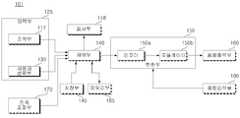
도 1은 본 발명의 일실시예에 따른 세탁물 처리기기(101)의 사시도이다. 도 2는 도 1에 도시된 세탁물 처리기기(101)의 개략적인 구성도이다. 도 1 및 도 2를 참조하면, 세탁물 처리기기(101)는, 캐비닛(111)과, 캐비닛(111) 내부에 배치되며 세탁물의 세정이 이루어지는 터브(122)와, 터브(122)를 구동시키는 모터(미도시)와, 터브(122)의 세탁수를 공급하는 세탁수공급장치(미도시)와, 세정이 끝난 후에 세탁수를 외부로 배출하는 배수장치(미도시)를 포함할 수 있다.1 is a perspective view of a
캐비닛(111)은, 캐비닛 본체(112)와, 캐비닛 본체(112)의 상측에 배치되어 결합하는 캐비닛 커버(113)와, 캐비닛 커버(114) 상측에 배치되며 세탁물 처리기기(101)의 운전을 제어하는 컨트롤패널(116)과, 컨트롤패널(116) 상측에 배치되며 캐비닛 본체(112)와 결합하는 탑 플레이트(115)를 포함한다. 캐비닛 커버(113)는 세탁물이 출입하는 홀(미도시)과, 상기 홀을 개폐 가능하도록 회동하는 도어(114)를 포함한다.The
컨트롤패널(116)은, 세탁물 처리기기의(101) 작동을 조작하기 위한 조작부(117)와, 사용자에게 세탁물 처리기기(101)의 작동상태를 소리로서(예컨데, 음성) 인지시키는 스피커 또는 버저(119)와, 세탁물 처리기기(101)의 작동상태를 제 어부(140)의 신호에 따라 이미지의 형태로 표시하는 표시부(118)를 포함할 수 있다.The
도 2를 참조하면, 세탁물 처리기기(101)는, 세탁물 처리기기(101)의 외부로부터 입력 신호를 입력받는 입력부(125)와, 제품정보를 저장하는 저장부(145)와, 입력부(125)를 통해 고장진단을 위한 제어명령을 포함하는 신호가 입력되면, 저장부(145)에 저장된 상기 제품정보를 로딩하고 제어신호를 출력하는 제어부(140)와, 상기 제품정보를 포함하는 제어신호를 적어도 하나의 음향신호로 변환하는 변환부(150)와, 상기 적어도 하나의 음향신호에 대응하여 음을 출력하는 음향출력부(160)를 포함한다. 음향출력부(160)에 의해 출력되는 음의 특성은 제어부(140)가 출력하는 상기 제어신호에 의해 조절될 수 있다.Referring to FIG. 2, the
저장부(145)는 제어부(140)에 포함될 수 있으며, EEPROM(Electrically Erasable Programmable Read-Only Memory)으로 구현되는 것이 가능하다.The
세탁물 처리기기(101)는 입력부(125)로부터 전송된 데이터를 임시 저장하는 메모리부(165)를 더 포함할 수 있다.The
입력부(125)는 고장진단을 위한 제어명령을 입력받는 사용자 선택부(130)를 포함할 수 있다. 사용자가 사용자 선택부(130)를 통해 상기 제어명령 또는 신호변환명령을 입력하면, 제어부(140)는 상기 제품 정보를 적어도 하나의 음향 신호로 변환하도록 변환부(150)를 제어할 수 있다. 음향출력부(140)는 변환부(150)에 의해 생성된 상기 적어도 하나의 음향신호를 음으로서 출력할 수 있다.The
변환부(150)는 인코더(150a, incoder)와 모듈레이터(150b, modulator)를 포 함할 수 있다. 인코더(150a)는 상기 제품정보의 각각의 비트(bit)를 심볼(symbol)들로 인코딩(incoding)한다. 모듈레이터(150b)는 상기 심볼들을 아날로그 신호로 변조한다. 상기 변조된 신호(즉, 전술한 적어도 하나의 음향신호) 음향출력부(160)로 출력되고, 음향출력부(160)는 상기 변조된 신호를 입력받아 음으로써 출력한다.The
모듈레이터(150b)는 상기 심볼들을 변조하는데, 예를 들어, 주파수 편이 방식(frequency shift keying method), 진폭 편이 방식(amplitude shift keying method) 또는 위상 편이 방식(phase shift keying method) 등을 이용할 수 있다. 상기 주파수 편이 방식이란, 상기 제품정보의 데이터 값들을 기 설정된 주파수로 변조하는 방식이고, 상기 진폭 변조 방식이란 상기 데이터 값에 따라 진폭 레벨을 다르게 하는 방식이고, 상기 위상 변조 방식이란 상기 제품정보의 데이터 값에 따라 위상을 다르게 하는 방식이다.The
음향출력부(160)는 버저(buzzer) 또는 스피커(speaker)로 구현될 수 있다.The
한편, 상기 제품정보는 세탁물 처리기기(101)의 운전정보 및/또는 고장정보 등을 포함할 수 있다.On the other hand, the product information may include operation information and / or failure information of the
세탁물 처리기기(101)는, 상기 음향신호의 진폭을 조절하는 진폭조절부(170)를 더 포함할 수 있다. 즉, 사용자가 진폭조절부(170)를 통하여 상기 음향신호의 진폭을 설정할 수 있다. 제어부(140)는, 변환부(150)가 상기 설정된 진폭에 따라 상기 제품정보를 상기 음향신호로 변환하도록 제어한다.The
한편, 세탁물 처리기기(101)는 조작부(117)를 더 포함할 수 있다. 조작부(117)는 일종의 컨트롤 수단으로 세탁물 처리기기(101)의 작동과 관련한 전반적 인 명령을 입력 받을 수 있다. 예를 들어, 사용자는 조작부(117)를 통해 세탁코스, 헹굼코스, 탈수코스 또는 건조코스 등의 사용자 운전코스를 설정할 수 있거나, 세탁 조건에 따라 다양한 옵션사항을 설정할 수 있다.On the other hand, the
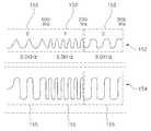
도 3은 도 2에 도시된 변환부(150)가 생성하는 제품정보를 포함하는 음향신호의 진폭특성을 도시한 그래프이다. 사용자가 사용자 선택부(130)를 통해 고장진단을 위한 제어명령을 입력하면, 제어부(140)는 변환부(150)가 상기 제품정보를 기 설정된 주파수 및 진폭 신호인 제 1음향신호(152)로 변환하도록 제어한다.3 is a graph illustrating amplitude characteristics of an acoustic signal including product information generated by the
제 1음향신호(152)는 복수개의 단위신호(153)를 포함하고, 각각의 단위신호(153)는 상기 기설정된 주파수 대역에 포함되는 제 1주파수신호 또는 제 2주파수신호이고, 상기 제 1주파수신호와 상기 제 2주파수신호는 서로 다른 주파수를 갖는 신호이다. 이하, 제 1음향신호(152)는 3Khz~4Khz인 주파수 대역의 신호이고, 상기 제 1주파수신호는 3.0Khz의 주파수신호이고, 상기 제 2주파수신호는 3.5Khz의 주파수신호인 것으로 설명한다.The
상기 제품정보는 0 또는 1의 논리적 데이터의 조합으로 이루어진 디지털데이터로 구성된다. 즉, 세탁물 처리기기(101)에 구비된 저장부(145)에 상기 제품정보가 디지털데이터로 저장되어 있고, 변환부(150)는 상기 디지털데이터를 주파수를 가지는 전기신호로 변환하는 일종의 디지털-아날로그 컨버터(이하 AD 컨버터라고 한다.)이다. 물론, 상기 AD컨버터는 아날로그 신호를 디지털신호로 변환하는 것도 가능하게 구현될 수 있다.The product information is composed of digital data consisting of a combination of zero or one logical data. That is, the product information is stored as digital data in the
변환부(150)는 상기 제품정보를 포함하는 디지털데이터를 아날로그 신호인 음향신호로 변환함에 있어서, 데이터 '0'을 제 1주파수 신호로 변환하고, 데이터 '1'을 제 2 주파수 신호로 변환한다. 이때, 제어부(140)는 상기 저장수단에 저장된 데이터를 검색하여, 데이터 '0'이 검색되면, 변환부(150)가 3.0Khz를 가지는 상기 제 1주파수 신호를 기 설정된 설정시간(t) 동안 생성하도록 하고, 데이터 '1'이 검색되면, 3.5Khz를 가지는 상기 제 2 주파수 신호를 시간 t 동안 생성하도록 제어한다. t=100ms 로 설정될 수 있다.The
사용자가 진폭조절부(170)를 통해 진폭을 설정하면, 제어부(140)는 변환부(160)가 상기 제품정보를 상기 설정된 진폭의 음향신호로 변환하도록 제어하고, 음향출력부(160)는 상기 설정된 진폭의 음을 출력한다. 즉, 주변환경 또는 통신망의 특성에 의해 신호의 간섭이 발생할 경우, 사용자는 진폭조절부(170)를 통해 상기 음향신호의 진폭을 크게 함으로서 상기 음의 크기를 키울 수 있다. 반면, 사용자가 조용한 환경을 원할 경우에는 진폭조절부(170)를 통해 상기 음향신호의 진폭을 작게 함으로서 상기 음의 크기를 줄일 수 있다.When the user sets the amplitude through the
이때, 사용자가 진폭조절부(170)를 통해 진폭을 설정하면, 제어부(140)는 변환부(150)가 상기 제품정보를 제 2음향신호(154)로 변환하도록 제어하고, 상기 제 2음향신호는 상기 제 1주파수신호와 주파수는 동일하나 진폭이 다른 제 3주파수신호 및 상기 제 2주파수신호와 주파수는 동일하나 진폭이 다른 제4주파수신호 중 적어도 하나를 포함한다. 즉, 제 1음향신호(152)와 제 2음향신호(154)는 주파수는 동일하나 진폭의 크기가 다르게 구성된다.In this case, when the user sets the amplitude through the
도 4는 본 발명의 일 실시예에 따른 세탁물 처리기기 시스템(301)의 개략적 인 구성도이다. 도 4를 참조하면, 세탁물 처리기기 시스템(301)은 전술한 세탁물 처리기기(101)와, 통신망(195)과 통신 가능한 외부단말기(190)와, 상기 제품정보가 포함된 음을 전달받아 제품정보로 역변환하는 관리장치(200)를 포함한다.4 is a schematic diagram of a laundry
관리장치(200)는, 상기 통신망을 통하여 받아들인 상기 음을 후술하는 신호변환부(220)로 전송함과 아울러, 신호변환부(220)로부터 일정한 신호가 전송되면 상기 통신망을 통해 외부단말기(190)로 송신하는 역할도 겸하는 송수신부(210)와, 송수신부(210)에서 수신한 상기 음을 후술하는 관리장치 제어부(230)가 판독 가능한 신호로 변환시키는 신호변환부(220)와, 신호변환부(220)로부터 받은 상기 신호를 판독하는 관리장치 제어부(230)와, 관리장치(200)를 제어하는 운영체제 및 상기 제품정보 등이 저장되는 관리장치 저장부(250)를 포함한다.The
관리장치 제어부(230)는 관리장치(200)의 전반적인 제어 및 상기 데이터를 분석하여 상기 제품정보를 판독하고, 관리장치 저장부(250)에 저장된 운영체제를 통해서 상기 제품정보에 포함된 제품의 고장정보 등을 분석하기 위한 컴퓨터 시스템으로 이루어진 것이 일반적이다. 따라서, 신호변환부(220)로 출력된 상기 신호는 상기 컴퓨터 시스템이 판독 가능한 형태인 디지털신호인 것이 바람직하다.The
한편, 상기 통신망은 유선 또는 이동통신망으로 구성될 수 있으며, 외부 단말기(190)는 유/무선 전화기 또는 이동통신 단말기로 구성될 수 있다. 일반적으로 가정에서는 세탁물 처리기기(101)가 베란다 등의 실외에 설치되는 경우가 많고, 상기 음향출력부(160)를 통해 출력되는 음을 수신하기 위해서는 이동통신 단말기등의 이동이 용이한 통신 장비가 쓰이는 것이 바람직하다.Meanwhile, the communication network may be configured by a wired or mobile communication network, and the
송수신부(210)는, 상기 통신망을 통해 외부단말기(190)와 연결되고, 신호변환부(220)와 전기적으로 연결되어 통신 가능하다. 즉, 송수신부(210)는 통신망(195)을 통하여 전송받은 상기 제품정보가 포함된 음을 아날로그 신호로 변환하고, 신호변환부(220)로부터 일정한 신호를 받아 상기 통신망을 통해 전송 가능한 신호로 변환하는 일종의 모뎀이다.The
신호변환부(220)는, 송수신부(210)로부터 상기 제품정보가 포함된 아날로그 신호를 전송받아 디지털신호로 변환하는 AD컨버터의 역할을 한다. 이때, 신호변환부(220)를 통하여 출력된 신호는 디지털 신호로서, 후술하는 관리장치 제어부(230)가 판독한다. 관리장치 제어부(230)는, 관리장치(200)를 전반적으로 제어함과 아울러, 신호변환부(220)로부터 출력된 상기 제품정보가 포함된 디지털신호를 판독하는 역할을 한다. 관리장치(200)는 상기 제품정보를 화상으로 출력하여 상기 제품정보에 포함된 운전정보 또는 고장정보를 수리자가 볼 수 있도록하는 관리장치 표시부(240)를 더 포함할 수 있다.The
관리장치 제어부(230)가 상기 디지털신호를 판독할 수 없는 경우 즉, 상기 제품정보를 포함하는 데이터를 판독하는 과정에 에러가 발생한 경우, 관리장치 제어부(230)는 송수신부(220)를 통해 재전송요청신호를 송신한다. 상기 재전송요청신호는 통신망(195)을 통하여 외부 단말기(190)로 전송되고, 사용자는 외부 단말기(190)의 스피커를 통하여 재전송요청음을 청취한다. 즉, 상기 재전송요청음은, "데이터가 제대로 전송되지 않았으니 다시 한번 전송버턴을 눌러주세요"와 같은 음성정보로 구성될 수 있다.When the
이때, 사용자가 사용자 선택부(130)를 통해 상기 제어명령(또는, 신호변환명령)을 다시 입력하면, 제어부(140)는 변환부(150)가 상기 제품정보를 상기 제 1음향신호(152)보다 더 큰 진폭을 가지는 제 2음향신호(154)로 변환하도록 제어한다. 물론, 사용자는 사용자 선택부(130)를 통해 상기 신호변환명령을 입력하기 전에 진폭조절부(170)를 통해 미리 상기 제 2음향신호(154)의 진폭을 설정할 수 있고, 이 경우, 제어부(140)는 변환부(150)가 상기 설정된 진폭에 따라 상기 제품정보를 제 2음향신호(154)로 변환시키도록하고, 음향출력부(160)는 제 2음향신호(154)에 대응하는 제 2음을 출력한다.In this case, when the user inputs the control command (or signal conversion command) again through the
한편, 세탁물 처리기기(101)는 외부로부터 음을 입력받는 음향입력부(180)를 더 포함할 수 있다. 세탁물 처리기기(101)의 운전에 이상이 발생한 경우, 사용자는 외부단말기(190)를 통하여 관리장치(200)와 통화연결을 한 후, 상기 통화 연결된 상태에서 외부 단말기(190)의 마이크로폰(미도시)을 세탁기의 음향출력부(160)와 근접한 거리로 가져다 댄다. 그 후, 사용자는 사용자 선택부(130)를 통해 고장진단을 위한 제어명령을 입력한다. 상기 제어명령이 입력되면, 제어부(140)는 변환부(150)가 상기 제품정보를 제 1음향신호(152)로 변환하도록 제어하고, 음향출력부(160)는 제 1음향신호(152)에 대응하는 제 1음을 출력한다. 이 경우, 관리장치 제어부(230)는, 상기 제품정보를 포함하고 신호변환부(220)를 통해 출력된 디지털신호를 판독한다. 이때, 상기 디지털신호의 판독이 어려울 경우, 관리장치 제어부(230)는 송수신부(210)가 재전송요청신호를 송신하도록 제어한다.On the other hand, the
한편, 음향입력부(180)는 일종의 마이크로폰으로써 외부로부터 소리를 입력 받는 장치이고, 음향입력부(180)로 입력된 외부음은 아날로그 신호로 변환되고, 변환부(150)는 상기 아날로그 신호를 디지털신호로 변환한다. 이때, 제어부(140)는 상기 디지털신호를 판독하여, 재전송요청이 포함된 경우, 변환부(150)가 상기 제품정보를 제 2음향신호(154)로 변환하도록 제어하고, 음향출력부(160)는 제 2음향신호(154)에 대응하는 상기 제 2음을 출력한다. 즉, 이 경우, 변환부(150)는 아날로그 신호를 디지털 신호로 변환시키는 역할을 한다.On the other hand, the
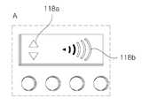
도 5는 도 1에 도시된 컨트롤 패널(116)의 확대 사시도이다. 도 6은 도 5에 도시된 A부분의 확대도이다. 도 3을 참조하면, A부분은 컨트롤패널(116)에 배치된 표시부(118), 조작부(117) 및 상기 음향신호의 진폭을 설정하는 진폭조절부 (117a) 및 출력부(150)를 통해 출력되는 상기 음향신호에 대응하는 음의 크기를 표시하는 디스플레이(117b, display)를 포함한다. 진폭조절부(117a)는, 사용자가 누르는 횟수에 따라 음향출력부(160)를 통해 출력되는 음의 크기를 키우거나 줄일 수 있는 장치로서, 푸시방식의 전자식/기계식 버튼으로 구성될 수 있다. 즉, 사용자가 일정회수 반복하여 진폭조절부(117a)를 누르면 상기 음의 크기가 커지다가 일정한 크기 이상에 도달한 후에는 다시 줄어들게 구성된다.FIG. 5 is an enlarged perspective view of the
디스플레이(117b)는 사용자에 의해 조절된 상기 음의 크기를 표시하기 위한 복수개의 LED장치를 포함할 수 있다. 즉, 상기 음의 크기가 증가함에 따라 상기 복수개의 LED 장치가 하측에서 상측으로 차례로 점등되게 하여 사용자로 하여금 현재의 상기 음의 크기를 시각적으로 인식할 수 있도록 한다.The
도 7은 도 5에 도시된 A부분의 다른 실시예이다. 도 7을 참조하면, 표시 부(118)는 터치스크린으로 구성된다. 즉, 표시부(118)의 표면에는 압력을 감지하는 소자가 배치되어 사용자가 표시부(118)의 표면에 압력을 가하면, 이를 감지하여 신호화함과 아울러, 표면에 화상을 출력할 수 있는 장치이다.FIG. 7 is another embodiment of part A shown in FIG. 5. Referring to FIG. 7, the
진폭조절부(118a)는 표시부(118)에 화상으로 표시된 버튼 모양으로 구성되어, 상기 버튼모양이 표시된 영역에 압력이 가해지면 제어부(140)에 진폭조절명령이 입력되어, 상기 음향신호의 진폭이 조절된다. 이때, 음향출력부(160)를 통하여 출력되는 음의 크기는 표시부(118)에 화상(118b)으로 표시된다.The
도 8는 도 5에 도시된 A부분의 또 다른 실시예이다. 도 8을 참조하면, 진폭조절부(170)는 다이얼식으로 구성되어 있으며, 다이얼(117c)을 좌우로 회전하여 상기 음향신호의 진폭을 조절하고, 상기 음향신호에 대응하여 출력되는 음의 크기를 표시부(118)가 화상(118b)으로 표시한다.FIG. 8 is another embodiment of part A shown in FIG. Referring to FIG. 8, the
도 9는 본 발명의 다른 실시예에 따른 세탁물 처리기기(102)의 개략적인 구성도이다. 도 9를 참조하면, 세탁물 처리기기(102)는, 제어명령을 입력받는 입력부(125)와, 제품정보를 적어도 하나의 음향신호로 변환하는 변환부(150), 상기 적어도 하나의 음향신호에 대응하는 음을 출력하는 음향출력부(160)를 포함한다.9 is a schematic configuration diagram of a
입력부(125)는 고장진단을 위한 제어명령을 입력받는 사용자 선택부(130)를 포함할 수 있다. 사용자가 사용자 선택부(130)를 통해 제어명령 또는 상기 제어명령을 입력하면, 제어부(140)는 상기 제품 정보를 적어도 하나의 음향 신호로 변환하도록 변환부(150)를 제어할 수 있다. 음향출력부(160)는 변환부(150)에 의해 생성된 상기 적어도 하나의 음향신호를 음으로서 세탁물 처리기기(102)의 외부로 출 력할 수 있다. 상기 음향신호는 음향출력부(160)를 구동시키는 전기신호로서, 주파수를 갖는 신호이다. 즉, 상기 음향신호를 구성하는 주파수의 특성에 따라 음향출력부(160)는 그에 대응하는 음을 출력하게 된다. 음향출력부(160)는 버져나 스피커 등으로 구성될 수 있다. 상기 제품정보는 제품의 운전정보, 고장정보 등을 포함할 수 있다.The
한편, 변환부(150)는 인코더(150a, incoder)와 모듈레이터(150b, modulator)를 포함할 수 있다. 인코더(150a)는 상기 제품정보의 각각의 비트(bit)를 심볼(symbol)들로 인코딩(incoding)할 수 있다. 모듈레이터(150b)는 상기 심볼들을 아날로그 신호로 변조한다. 상기 변조된 신호(즉, 전술한 적어도 하나의 음향신호) 음향출력부(160)로 출력되고, 음향출력부(160)는 상기 변조된 신호를 입력받아 음으로써 출력한다.On the other hand, the
모듈레이터(150b)는 상기 심볼들을 변조하는데, 예를 들어, 주파수 편이 방식(frequency shift keying method), 진폭 편이 방식(amplitude shift keying method) 또는 위상 편이 방식(phase shift keying method) 등을 이용할 수 있다. 상기 주파수 편이 방식이란, 상기 제품정보의 데이터 값들을 기 설정된 주파수로 변조하는 방식이고, 상기 진폭 변조 방식이란 상기 데이터 값에 따라 진폭 레벨을 다르게 하는 방식이고, 상기 위상 변조 방식이란 상기 제품정보의 데이터 값이 따라 위상을 다르게 하는 방식이다.The
한편, 조작부(117)는 일종의 컨트롤 수단으로 세탁물 처리기기(100)의 작동과 관련한 전반적인 명령을 입력 받을 수 있다. 예를 들어, 사용자는 조작부(117) 를 통해 세탁코스, 헹굼코스, 탈수코스 또는 건조코스 등의 사용자 운전코스를 설정할 수 있거나, 세탁 조건에 따라 다양한 옵션사항을 설정할 수 있다.On the other hand, the
도 10은 도 9에 도시된 변환부(150)가 생성하는 제품정보를 포함하는 음향신호의 주파수 특성을 도시한 그래프이다. 사용자가 고장진단을 위한 제어신호를 입력하면, 제어부(140)는 변환부(150)가 상기 제품정보를 기설정된 주파수대역의 신호인 제 1음향신호(252)로 변환하도록 제어한다.FIG. 10 is a graph illustrating frequency characteristics of an acoustic signal including product information generated by the
제 1음향신호(252)는 복수개의 제 1단위신호(253)를 포함하고, 각각의 제 1단위신호(253)는 상기 기설정된 주파수 대역에 포함되는 제 1주파수신호 또는 제 2주파수신호이고, 상기 제 1주파수신호와 상기 제 2주파수신호는 서로 다른 주파수를 갖는 신호이다. 이하, 제1음향신호(252)는 2Khz~3Khz인 주파수 대역의 신호이고, 상기 제 1주파수신호는 2.5Khz의 주파수신호이고, 상기 제 2주파수신호는 2.9Khz의 주파수신호인 것으로 설명한다.The
상기 제품정보는 0 또는 1의 논리적 데이터의 조합으로 이루어진 디지털데이터로 구성된다. 상기 제품정보는 세탁물 처리기기(102)에 구비된 저장부(145)에 디지털 데이터로로서 저장될 수 있고, 변환부(150)는 상기 디지털데이터를 주파수를 가지는 전기신호로 변환하는 일종의 디지털-아날로그 컨버터(이하 AD 컨버터라고 한다.)이다. 물론, 상기 AD컨버터는 아날로그 신호를 디지털신호로 변환하는 것도 가능하게 구현될 수 있다.The product information is composed of digital data consisting of a combination of zero or one logical data. The product information may be stored as digital data in a
변환부(150)는 상기 제품정보를 포함하는 디지털데이터를 아날로그 신호인 음향신호로 변환함에 있어서, 데이터 '0'을 제 1주파수 신호로 변환하고, 데이터 '1'을 제 2 주파수 신호로 변환한다. 이때, 제어부(140)는 저장부(145)에 저장된 데이터를 검색하여, 데이터 '0'이 검색되면, 변환부(150)가 2.5Khz를 가지는 상기 제 1주파수 신호를 기 설정된 설정시간(t) 동안 생성하도록 하고, 데이터 '1'이 검색되면, 2.9Khz를 가지는 상기 제 2 주파수 신호를 시간 t 동안 생성하도록 제어한다. t=100ms 로 설정될 수 있다.The
세탁물 처리기기(102)는, 보다 정확하게 제품정보를 전달하기 위하여, 상기 제품정보를 포함하고 진동특성이 서로 다른 음을 복수회 출력한다. 즉, 변환부(150)는 상기 제품정보를 주파수 대역이 다른 복수의 음향신호들로 변환하고, 음향출력부(160)는 상기 복수의 음향신호들에 대응하는 서로 다른 진동특성을 가진 복수의 음들을 연속하여 출력한다. 이하, 제 1음을 출력한 후 제 2음을 출력하는 것으로 설명한다.The
변환부(150)는 상기 제품정보를 제 1음향신호(252)로 변환한 후, 다시 상기 제품정보를 제 2음향신호(254)로 변환한다. 제 2음향신호(154)는 제 1음향신호(252)와 주파수 대역을 달리하는 신호이다. 이때, 제 2음향신호(254)는 복수개의 제 2단위신호(255)를 포함하고, 각각의 제 2단위신호(255)는 제 2음향신호(254)의 주파수 대역에 포함되는 제 3 주파수신호 또는 상기 제 3주파수신호와 주파수가 다른 제 4주파수신호이다. 이하, 제 2음향신호(254)는 3Khz~4Khz대의 대역폭 신호로 구성되고, 상기 제 3주파수 신호는 3.0Khz의 주파수 신호이고, 상기 제 4주파수 신호는 3.5Khz의 주파수 신호인 것으로 설명한다.The
전술한 바와 같이, 변환부(150)가 상기 제품정보를 주파수대역이 서로 다른 제 1음향신호(252) 및 제 2음향신호(254)로 변환하기 때문에, 결과적으로 음향출력부(160)는 제 1음향신호(252)에 대응하는 상기 제 1음 및 제 2음향신호(254)에 대응하는 상기 제 2음을 출력한다. 이때, 상기 제 1음 및 제 2음은 상기 제품정보를 각각 포함한다.As described above, the
따라서, 세탁물 처리기기(102)의 주변환경에 의해 신호의 간섭현상이 발생한 경우에도, 세탁물 처리기기(102)는 상기 제품정보를 서로 진동특성이 상이한 상기 제 1음 및, 상기 제 2음으로 연속하여 출력하기 때문에, 상기 제품정보를 보다 정확하게 전달할 수 있다. 물론, 음향출력부(160)는 서로 주파수대역이 다른 두개 이상의 음을 연속하여 출력할 수도 있다.Therefore, even when the interference of the signal occurs due to the surrounding environment of the
도 9를 참조하면, 세탁물 처리기기(102)는 상기 음향신호의 주파수대역 및, 상기 음향신호를 구성하는 단위신호의 주파수를 선택하는 주파수 선택부(175)를 더 포함할 수 있다. 즉, 사용자가 주파수 선택부(175)를 통하여 상기 음향신호의 주파수 대역 및 상기 음향신호가 포함하는 제 1주파수신호 및 제 2주파수신호의 각각의 주파수 선택명령을 입력한다. 제어부(140)는 상기 주파수 선택명령에 따라 변환부(150)가 상기 선택된 결과에 따라 상기 제품정보를 상기 음향신호로 변환하도록 제어한다. 한편, 주파수 선택부(175)는 기 설정된 복수의 주파수설정모드에 따라 상기 음향신호의 주파수 대역 및 상기 제 1주파수신호 및 제 2 주파수신호 각각의 주파수를 선택하게 구성될 수도 있다.Referring to FIG. 9, the
도 11은 본 발명의 다른 실시예에 따른 세탁물 처리기기 시스템(302)의 개략적인 구성도이다. 도 11을 참조하면, 세탁물 처리기기 시스템(302)은 전술한 세탁 물 처리기기(102)와, 통신망(195)과 통신가능한 외부단말기(190)와, 상기 제품정보가 포함된 음을 전달받아 제품정보로 역변환하는 관리장치(200)를 포함한다.11 is a schematic diagram of a laundry
관리장치(200)는, 통신망(195)을 통하여 받아들인 상기 음을 후술하는 신호변환부(220)로 전송함과 아울러, 신호변환부(220)로부터 일정한 신호가 전송되면 상기 통신망을 통해 외부단말기(190)로 송신하는 역할도 겸하는 송수신부(210)와, 송수신부(210)에서 수신한 상기 음을 후술하는 관리장치 제어부(230)가 판독 가능한 신호로 변환시키는 신호변환부(220)와, 신호변환부(220)로부터 받은 상기 신호를 판독하는 관리장치 제어부(230)와, 관리장치(200)를 제어하는 운영체제 및 상기 제품정보 등이 저장되는 관리장치 저장부(250)를 포함한다.The
관리장치 제어부(230)는 관리장치(200)의 전반적인 제어 및 상기 데이터를 분석하여 상기 제품정보를 판독하고, 관리장치 저장부(250)에 저장된 운영체제를 통해서 상기 제품정보에 포함된 제품의 고장정보 등을 분석하기 위한 컴퓨터 시스템으로 이루어진 것이 일반적이다. 따라서, 신호변환부(220)로 출력된 상기 신호는 상기 컴퓨터 시스템이 판독가능한 형태인 디지털신호인 것이 바람직하다.The
한편, 통신망(195)은 유선 또는 이동통신망으로 구성될 수 있으며, 외부 단말기(190)는 유/무선 전화기 또는 이동통신 단말기로 구성될 수 있다. 일반적으로 가정에서는 세탁물 처리기기(102)가 베란다 등의 실외에 설치되는 경우가 많고, 음향출력부(160)를 통해 출력되는 음을 수신하기 위해서는 이동통신 단말기등의 이동이 용이한 통신 장비가 쓰이는 것이 바람직하다.Meanwhile, the
송수신부(210)는, 상기 통신망을 통해 외부단말기(160)와 연결되고, 신호변 환부(220)와 전기적으로 연결되어 통신 가능하다. 즉, 송수신부(210)는 상기 통신망을 통하여 전송받은 상기 제품정보가 포함된 음을 아날로그 신호로 변환하고, 신호변환부(220)로부터 일정한 신호를 받아 상기 통신망을 통해 전송가능한 신호로 변환하는 일종의 모뎀이다.The
신호변환부(220)는, 송수신부(210)로부터 상기 제품정보가 포함된 아날로그 신호를 전송받아 디지털신호로 변환하는 AD컨버터의 역할을 한다. 이때, 신호변환부(220)를 통하여 출력된 신호는 디지털 신호로서, 후술하는 관리장치 제어부(230)가 판독한다.The
관리장치 제어부(230)는, 관리장치(200)를 전반적으로 제어함과 아울러, 신호변환부(220)로부터 출력된 상기 제품정보가 포함된 디지털신호를 판독하는 역할을 한다. 이때, 관리장치 제어부(230)가 상기 디지털신호를 판독할 수 없는 경우 즉, 상기 제품정보를 포함하는 데이터를 판독하는 과정에 에러가 발생한 경우, 관리장치 제어부(230)는 송수신부(220)를 통해 재전송 요청 정보가 포함된 신호를 송신한다.The management
관리장치(200)는 상기 제품정보를 화상으로 출력하여 상기 제품정보에 포함된 운전정보 또는 고장정보를 수리자가 볼 수 있도록하는 관리장치 표시부(240)를 더 포함할 수 있다.The
도 12는 세탁물 처리기기 시스템(302)의 제어흐름의 일례를 도시한 순서도이다. 도11 및 도 12를 참조하면, 사용자는 세탁물 처리기기(102)의 운전에 이상이 발생한 경우, 외부단말기(190)를 통하여 관리장치(200)와 통화연결을 한 후, 상기 통화연결된 상태에서 외부 단말기(190)의 마이크로폰(미도시)을 세탁기의 음향출력부(160)와 근접한 거리로 가져다 댄다.12 is a flow chart showing an example of the control flow of the laundry
그 후, 사용자는 사용자 선택부(130)를 통해 고장진단을 위한 제어명령을 입력한다. 상기 제어명령이 입력되면, 제어부(140)는 변환부(150)가 상기 제품정보를 제 1음향신호(252)로 변환하도록 제어하고, 음향출력부(160)는 제 1음향신호(252)에 대응하는 제 1음을 출력한다.(S110)Thereafter, the user inputs a control command for fault diagnosis through the
한편, 관리장치 제어부(230)는, 상기 제품정보를 포함하고 신호변환부(150)를 통해 출력된 디지털신호를 판독한다.(S120) 이때, 상기 디지털신호의 판독이 어려울 경우, 관리장치 제어부(230)는 송수신부(210)가 재전송요청신호를 송신하도록 제어한다.(S130)Meanwhile, the management
상기 재전송요청신호는 상기 통신망을 통하여 외부 단말기(190)에 수신되고, 사용자는 외부 단말기(190)의 스피커를 통하여 상기 재전송 요청 정보를 청취한다. 즉, 상기 재전송 요청 정보는, "데이터가 제대로 전송되지 않았으니 다시 한번 전송버턴을 눌러주세요"와 같은 음성정보로 구성된다.The retransmission request signal is received by the
이때, 사용자가 사용자 선택부(130)를 통해 재전송명령을 입력하면(S140), 제어부(140)는 변환부(150)가 상기 제품정보를 제 2음향신호(254)로 변환하도록 제어하고, 음향출력부(160)는 제 2음향신호(254)에 대응하는 제 2음을 출력한다(S150).At this time, when the user inputs a retransmission command through the user selection unit 130 (S140), the
즉, 사용자가 외부 단말기(190)를 통하여 관리장치(200)로부터 재전송요청을 받았을 경우, 기 출력한 상기 제 1음과 다른 진동특성을 가지는 상기 제 2음을 출 력할 것인지를 결정한다.That is, when the user receives the retransmission request from the
이 경우, 사용자는 주파수 선택부(175)를 통하여 제 2음향신호(254)의 주파수 특성을 결정한 후 사용자 선택부(130)를 통해서 상기 신호변환명령을 입력할 수도 있다.In this case, the user may determine the frequency characteristic of the
도 13은 세탁물 처리기기 시스템(302)의 제어흐름의 다른 예를 도시한 순서도이다. 도 11 및 도 13을 참조하면, 세탁물 처리기기(102)는 외부로부터 음을 입력받는 음향입력부(180)를 더 포함한다.13 is a flowchart illustrating another example of the control flow of the laundry
사용자는 세탁물 처리기기(102)의 운전에 이상이 발생한 경우, 외부단말기(190)를 통하여 관리장치(200)와 통화연결을 한 후, 상기 통화연결된 상태에서 외부 단말기(190)의 마이크로폰(미도시)을 세탁기의 음향출력부(160)와 근접한 거리로 가져다 댄다. 그 후, 사용자는 사용자 선택부(130)를 통해 신호변환명령을 입력한다. 상기 신호변환명령이 입력되면, 제어부(140)는 변환부(150)가 상기 제품정보를 제 1음향신호(252)로 변환하도록 제어하고, 음향출력부(160)는 제 1음향신호(152)에 대응하는 제 1음을 출력한다(S210).When the user has an abnormality in the operation of the
관리장치 제어부(230)는, 상기 제품정보를 포함하고 신호변환부(150)를 통해 출력된 디지털신호를 판독한다.(S220) 이때, 상기 디지털신호의 판독이 어려울 경우, 관리장치 제어부(230)는 송수신부(210)가 재전송요청신호를 송신하도록 제어한다.(S230)The management
한편, 음향입력부(180)는 일종의 마이크로폰으로써 외부로부터 소리를 입력받는 장치이고, 음향입력부(180)로 입력된 외부음은 아날로그 신호로 변환되고, 변 환부(150)는 상기 아날로그 신호를 디지털신호로 변환한다. 이때, 제어부(140)는 상기 디지털신호를 판독하여, 재전송요청이 포함된 경우, 변환부(150)가 상기 제품정보를 제 2음향신호(254)로 변환하도록 제어하고, 음향출력부(160)는 제 2음향신호(254)에 대응하는 상기 제 2음을 출력한다(S250). 즉, 이경우, 변환부(150)는 아날로그 신호를 디지털 신호로 변환시키는 역할을 한다.On the other hand, the
본 발명은 도면에 도시된 실시예를 참고로 설명되었으나 이는 예시적인 것에 불과하며, 본 기술 분야의 통상의 지식을 가진 자라면 이로부터 다양한 변형 및 균등한 다른 실시예가 가능하다는 점을 이해할 것이다. 따라서, 본 발명의 진정한 기술적 보호 범위는 첨부된 특허청구범위의 기술적 사상에 의하여 정해져야 할 것이다.Although the present invention has been described with reference to the embodiments shown in the drawings, this is merely exemplary, and it will be understood by those skilled in the art that various modifications and equivalent other embodiments are possible. Therefore, the true technical protection scope of the present invention will be defined by the technical spirit of the appended claims.
도 1은 본 발명의 일실시예에 따른 세탁물 처리기기의 사시도이다.1 is a perspective view of a laundry treatment machine according to an embodiment of the present invention.
도 2는 도 1에 도시된 세탁물 처리기기의 개략적인 구성도이다.2 is a schematic configuration diagram of a laundry treatment machine shown in FIG. 1.
도 3은 도 2에 도시된 변환부가 생성하는 제품정보를 포함하는 음향신호의 진폭특성을 도시한 그래프이다.FIG. 3 is a graph illustrating amplitude characteristics of an acoustic signal including product information generated by the converter illustrated in FIG. 2.
도 4는 본 발명의 일 실시예에 따른 세탁물 처리기기 시스템의 개략적인 구성도이다.Figure 4 is a schematic diagram of a laundry treatment machine system according to an embodiment of the present invention.
도 5는 도 1에 도시된 컨트롤 패널의 확대 사시도이다. 도 6은 도 5에 도시된 A부분의 확대도이다.FIG. 5 is an enlarged perspective view of the control panel shown in FIG. 1. FIG. 6 is an enlarged view of a portion A shown in FIG. 5.
도 7은 도 5에 도시된 A부분의 다른 실시예이다.FIG. 7 is another embodiment of part A shown in FIG. 5.
도 8는 도 5에 도시된 A부분의 또 다른 실시예이다.FIG. 8 is another embodiment of part A shown in FIG.
도 9는 본 발명의 다른 실시예에 따른 세탁물 처리기기의 개략적인 구성도이다.9 is a schematic configuration diagram of a laundry treatment machine according to another embodiment of the present invention.
도 10은 도 9에 도시된 변환부가 생성하는 제품정보를 포함하는 음향신호의 주파수 특성을 도시한 그래프이다.FIG. 10 is a graph illustrating frequency characteristics of an acoustic signal including product information generated by the converter illustrated in FIG. 9.
도 11은 본 발명의 다른 실시예에 따른 세탁물 처리기기 시스템의 개략적인 구성도이다.11 is a schematic configuration diagram of a laundry treatment machine system according to another embodiment of the present invention.
도 12는 세탁물 처리기기 시스템의 제어흐름의 일 예를 도시한 순서도이다.12 is a flow chart showing an example of the control flow of the laundry treatment machine system.
도 13은 세탁물 처리기기 시스템의 제어흐름의 다른 예를 도시한 순서도이다.13 is a flow chart showing another example of the control flow of the laundry treatment machine system.
<도면의 주요 부분에 대한 부호의 설명><Explanation of symbols for the main parts of the drawings>
101, 102: 가전기기, 세탁물 처리기기125: 입력부101, 102: home appliances, laundry treatment equipment 125: input unit
117: 조작부130: 사용자 선택부117: operation unit 130: user selection unit
118: 표시부145: 저장부118: display unit 145: storage unit
150: 변환부160: 음향출력부150: converter 160: sound output unit
170: 진폭 조절부175: 주파수 선택부170: amplitude control unit 175: frequency selection unit
180: 음향입력부190: 외부 단말기180: sound input unit 190: external terminal
195: 통신망200: 관리장치195: communication network 200: management device
210: 송수신부220: 신호변환부210: transceiver 220: signal conversion unit
230: 관리장치 제어부240: 관리장치 표시부230: management device control unit 240: management device display unit
250: 관리장치 저장부250: management device storage unit
Claims (41)
Translated fromKoreanApplications Claiming Priority (4)
| Application Number | Priority Date | Filing Date | Title |
|---|---|---|---|
| KR20080040679 | 2008-04-30 | ||
| KR20080040678 | 2008-04-30 | ||
| KR1020080040679 | 2008-04-30 | ||
| KR1020080040678 | 2008-04-30 |
Publications (2)
| Publication Number | Publication Date |
|---|---|
| KR20090115078Atrue KR20090115078A (en) | 2009-11-04 |
| KR101464295B1 KR101464295B1 (en) | 2014-11-21 |
Family
ID=41681279
Family Applications (1)
| Application Number | Title | Priority Date | Filing Date |
|---|---|---|---|
| KR1020090038248AExpired - Fee RelatedKR101464295B1 (en) | 2008-04-30 | 2009-04-30 | Home appliance and home appliance system |
Country Status (2)
| Country | Link |
|---|---|
| US (1) | US20100040213A1 (en) |
| KR (1) | KR101464295B1 (en) |
Cited By (3)
| Publication number | Priority date | Publication date | Assignee | Title |
|---|---|---|---|---|
| WO2012005512A3 (en)* | 2010-07-06 | 2012-05-18 | 엘지전자 주식회사 | Apparatus for diagnosing home appliances |
| US9013320B2 (en) | 2012-07-09 | 2015-04-21 | Lg Electronics Inc. | Home appliance and its system |
| US9495859B2 (en) | 2012-07-03 | 2016-11-15 | Lg Electronics Inc. | Home appliance and method of outputting signal sound for diagnosis |
Families Citing this family (21)
| Publication number | Priority date | Publication date | Assignee | Title |
|---|---|---|---|---|
| US8286288B2 (en) | 2008-07-01 | 2012-10-16 | Whirlpool Corporation | Method of indicating operational information for a bulk dispensing system |
| US7950088B2 (en)* | 2008-07-01 | 2011-05-31 | Whirlpool Corporation | Method of indicating operational information for a dispensing system having both single use and bulk dispensing |
| US8397544B2 (en) | 2008-07-01 | 2013-03-19 | Whirlpool Corporation | Household cleaning appliance with a single water flow path for both non-bulk and bulk dispensing |
| US10138587B2 (en) | 2008-07-01 | 2018-11-27 | Whirlpool Corporation | Household cleaning appliance with a dispensing system operable between a single use dispensing system and a bulk dispensing system |
| US8196441B2 (en) | 2008-07-01 | 2012-06-12 | Whirlpool Corporation | Household cleaning appliance with a dispensing system operable between a single use dispensing system and a bulk dispensing system |
| US20100000264A1 (en) | 2008-07-01 | 2010-01-07 | Whirlpool Corporation | Method for converting a household cleaning appliance with a non-bulk dispensing system to a household cleaning appliance with a bulk dispensing system |
| US9709327B2 (en)* | 2011-03-17 | 2017-07-18 | Dry Ventures, Inc. | Rapid rescue of inundated cellphones |
| KR20130029250A (en)* | 2011-09-14 | 2013-03-22 | 한국전자통신연구원 | Method and apparatus for requesting examination and fault detection |
| KR101985337B1 (en)* | 2011-10-26 | 2019-09-04 | 삼성전자 주식회사 | Method for transmitting of message according to electronic device operation and system therefor |
| US10876792B2 (en) | 2012-02-01 | 2020-12-29 | Revive Electronics, LLC | Methods and apparatuses for drying electronic devices |
| US11713924B2 (en) | 2012-02-01 | 2023-08-01 | Revive Electronics, LLC | Methods and apparatuses for drying electronic devices |
| US10690413B2 (en) | 2012-02-01 | 2020-06-23 | Revive Electronics, LLC | Methods and apparatuses for drying electronic devices |
| US12276454B2 (en) | 2020-04-21 | 2025-04-15 | Revive Electronics, LLC | Methods and apparatuses for drying electronic devices |
| US12215925B2 (en) | 2020-04-21 | 2025-02-04 | Revive Electronics, LLC | Methods and apparatuses for drying electronic devices |
| US10240867B2 (en) | 2012-02-01 | 2019-03-26 | Revive Electronics, LLC | Methods and apparatuses for drying electronic devices |
| US12281847B2 (en) | 2020-04-21 | 2025-04-22 | Revive Electronics, LLC | Methods and apparatuses for drying electronic devices |
| AT514901A1 (en)* | 2013-07-25 | 2015-04-15 | Fronius Int Gmbh | energy device |
| KR101828460B1 (en)* | 2013-07-30 | 2018-02-14 | 삼성전자주식회사 | Home appliance and controlling method thereof |
| CN104168132B (en)* | 2014-06-18 | 2017-12-12 | 华为技术有限公司 | Method for diagnosing faults, equipment and system |
| US11640232B2 (en) | 2021-09-02 | 2023-05-02 | Electrolux Home Products, Inc. | Cost efficient method for communicating from an appliance to an external device |
| CN119105301A (en)* | 2024-09-02 | 2024-12-10 | 珠海格力电器股份有限公司 | Electrical equipment linkage control method, device, electronic equipment and smart home system |
Family Cites Families (50)
| Publication number | Priority date | Publication date | Assignee | Title |
|---|---|---|---|---|
| US3910322A (en)* | 1972-08-24 | 1975-10-07 | Westinghouse Electric Corp | Test set controlled by a remotely positioned digital computer |
| JPS5894288A (en)* | 1981-11-30 | 1983-06-04 | Sony Corp | Video signal recording device |
| US5103214A (en)* | 1990-09-07 | 1992-04-07 | Minnesota Mining And Manufacturing Company | Auxiliary alarm |
| US5210784A (en)* | 1991-06-28 | 1993-05-11 | Lifeline Systems, Inc. | Adaptive speakerphone system |
| US5268666A (en)* | 1991-12-23 | 1993-12-07 | At&T Bell Laboratories | Appliance control system providing out-of-context usage |
| US5452344A (en)* | 1992-05-29 | 1995-09-19 | Datran Systems Corporation | Communication over power lines |
| JPH06284216A (en)* | 1993-03-25 | 1994-10-07 | Sony Corp | Check and adjustment system for electronic device using telephone line |
| US5774529A (en)* | 1994-09-28 | 1998-06-30 | Johannsen; James | Apparatus to provide a remote display of the operating condition of a water treatment system |
| JP3197785B2 (en)* | 1995-05-15 | 2001-08-13 | 三洋電機株式会社 | Remote management system |
| KR19990000871A (en)* | 1997-06-11 | 1999-01-15 | 배순훈 | How to process the service mode of the washing machine |
| EP0887989A3 (en)* | 1997-06-25 | 2001-02-28 | FISHER & PAYKEL LIMITED | Appliance communication system |
| US6759954B1 (en)* | 1997-10-15 | 2004-07-06 | Hubbell Incorporated | Multi-dimensional vector-based occupancy sensor and method of operating same |
| US6121593A (en)* | 1998-08-19 | 2000-09-19 | Duck Creek Energy, Inc. | Home appliances provided with control systems which may be actuated from a remote location |
| IL127569A0 (en)* | 1998-09-16 | 1999-10-28 | Comsense Technologies Ltd | Interactive toys |
| US6763458B1 (en)* | 1999-09-27 | 2004-07-13 | Captaris, Inc. | System and method for installing and servicing an operating system in a computer or information appliance |
| US7337457B2 (en)* | 2000-04-12 | 2008-02-26 | Lg Electronics Inc. | Apparatus and method for providing and obtaining product information through a broadcast signal |
| AU7879801A (en)* | 2000-08-05 | 2002-02-18 | Lg Electronics Inc | Washing machine with device for data exchange to/from external device |
| TW593950B (en)* | 2000-09-11 | 2004-06-21 | Toshiba Corp | Remote inspection system for refrigerator |
| US6778868B2 (en)* | 2000-09-12 | 2004-08-17 | Kabushiki Kaisha Toshiba | Remote control of laundry appliance |
| US6906617B1 (en)* | 2000-11-17 | 2005-06-14 | Koninklijke Philips Electronics N.V. | Intelligent appliance home network |
| KR100411057B1 (en)* | 2000-12-27 | 2003-12-18 | 현대자동차주식회사 | Method for detecting gear state by using frequency demodulation method |
| US6710715B2 (en)* | 2001-01-25 | 2004-03-23 | Douglas Arthur Deeds | Alarm system with integrated weather alert function |
| KR100434270B1 (en)* | 2001-05-30 | 2004-06-04 | 엘지전자 주식회사 | Control System for Home Appliance Network |
| US6515909B1 (en)* | 2001-10-05 | 2003-02-04 | Micron Technology Inc. | Flash memory device with a variable erase pulse |
| US6570480B1 (en)* | 2002-01-02 | 2003-05-27 | Albert Huang | Circuit breaker |
| JP2003204596A (en)* | 2002-01-04 | 2003-07-18 | Matsushita Electric Ind Co Ltd | Loudspeaker broadcasting system and loudspeaker |
| US6697466B2 (en)* | 2002-03-05 | 2004-02-24 | Emware, Inc. | Audio status communication from an embedded device |
| US6775642B2 (en)* | 2002-04-17 | 2004-08-10 | Motorola, Inc. | Fault detection system having audio analysis and method of using the same |
| US6741554B2 (en)* | 2002-08-16 | 2004-05-25 | Motorola Inc. | Method and apparatus for reliably communicating information packets in a wireless communication network |
| JP4084694B2 (en)* | 2003-04-22 | 2008-04-30 | シャープ株式会社 | Washing machine |
| CA2528045A1 (en)* | 2003-06-05 | 2004-12-16 | Enfo Broadcast As | A method and a system for automatic management of demand for non-durables |
| DE10345359B4 (en)* | 2003-09-29 | 2006-11-02 | Berghof Labor- Und Automationstechnik Gmbh | Serial data bus, motion system and method for event-driven transmission of messages |
| US7424809B2 (en)* | 2003-10-23 | 2008-09-16 | Lg Electronics Inc. | Washing machine with melody generating assembly |
| GB0328708D0 (en)* | 2003-12-11 | 2004-01-14 | Ncr Int Inc | An acoustic coupling product label |
| US7319407B2 (en)* | 2003-12-19 | 2008-01-15 | Lg Electronics Inc. | Display unit for refrigerator |
| KR100600734B1 (en)* | 2004-02-25 | 2006-07-14 | 엘지전자 주식회사 | Home network system and its control method |
| US7439439B2 (en)* | 2004-03-09 | 2008-10-21 | Electrolux Home Products, Inc. | Appliance audio notification device |
| JP2005309077A (en)* | 2004-04-21 | 2005-11-04 | Fuji Xerox Co Ltd | Fault diagnostic method, fault diagnostic system, transporting device, and image forming apparatus, and program and storage medium |
| JP4828812B2 (en)* | 2004-09-27 | 2011-11-30 | 株式会社東芝 | Television broadcast receiver |
| CN100555238C (en)* | 2004-12-17 | 2009-10-28 | 韩国标准科学研究院 | Be used for the emergency protection of vacuum pump and the accurate diagnostic method and the accurate diagnostic system of anticipatory maintenance |
| DE102005013418A1 (en)* | 2005-03-23 | 2006-09-28 | B. Braun Medizintechnologie Gmbh | Blood treatment device with alarm device |
| US7498936B2 (en)* | 2005-04-01 | 2009-03-03 | Strauss Acquisitions, L.L.C. | Wireless event status communication system, device and method |
| CN101305350A (en)* | 2005-06-09 | 2008-11-12 | 惠而浦公司 | Software architecture system and method for communicating with and managing at least one component within a household appliance |
| US8027752B2 (en)* | 2005-06-09 | 2011-09-27 | Whirlpool Corporation | Network for changing resource consumption in an appliance |
| US8204189B2 (en)* | 2006-08-11 | 2012-06-19 | Fisher & Paykel Appliances Limited | Data download system and method |
| JP2008268187A (en)* | 2007-03-26 | 2008-11-06 | Nippon Steel Corp | Abnormality diagnosis method and apparatus for extremely low speed rotating machine |
| KR101627219B1 (en)* | 2008-04-29 | 2016-06-03 | 엘지전자 주식회사 | Home appliance and home appliance system |
| US20090282308A1 (en)* | 2008-05-09 | 2009-11-12 | Jan Gutsche | Memory Cell Arrangement and Method for Reading State Information From a Memory Cell Bypassing an Error Detection Circuit |
| KR20110010374A (en)* | 2009-07-24 | 2011-02-01 | 엘지전자 주식회사 | Home appliance diagnostic system and method |
| KR101472402B1 (en)* | 2009-07-31 | 2014-12-12 | 엘지전자 주식회사 | Home appliance diagnosis system and its diagnosis method |
- 2009
- 2009-04-29USUS12/432,132patent/US20100040213A1/ennot_activeAbandoned
- 2009-04-30KRKR1020090038248Apatent/KR101464295B1/ennot_activeExpired - Fee Related
Cited By (3)
| Publication number | Priority date | Publication date | Assignee | Title |
|---|---|---|---|---|
| WO2012005512A3 (en)* | 2010-07-06 | 2012-05-18 | 엘지전자 주식회사 | Apparatus for diagnosing home appliances |
| US9495859B2 (en) | 2012-07-03 | 2016-11-15 | Lg Electronics Inc. | Home appliance and method of outputting signal sound for diagnosis |
| US9013320B2 (en) | 2012-07-09 | 2015-04-21 | Lg Electronics Inc. | Home appliance and its system |
Also Published As
| Publication number | Publication date |
|---|---|
| KR101464295B1 (en) | 2014-11-21 |
| US20100040213A1 (en) | 2010-02-18 |
Similar Documents
| Publication | Publication Date | Title |
|---|---|---|
| KR101464295B1 (en) | Home appliance and home appliance system | |
| KR101629644B1 (en) | Home appliance and home appliance system | |
| EP2277302B1 (en) | Home appliance and home appliance system | |
| EP2277281B1 (en) | Home appliance system and operation method thereof | |
| KR20110010374A (en) | Home appliance diagnostic system and method | |
| US20090323913A1 (en) | Home appliance and home appliance system | |
| US8761361B2 (en) | Management unit with microphone | |
| US8532273B2 (en) | Home appliance and home appliance system | |
| KR100466361B1 (en) | Telephone having a function of a home-gateway | |
| KR20110010373A (en) | Home appliance diagnostic system and method | |
| JP2004218848A (en) | Remote controller communication system for housing equipment and instrument | |
| JP2010010779A (en) | Remote controller for water heater and water heater | |
| CA2801725C (en) | Management unit with microphone | |
| KR19980021099A (en) | Washing machine with remote control | |
| KR20000017568U (en) | An integrating controlling device of household electric appliances using remote controller with multi-function | |
| KR20100026861A (en) | Home appliance system | |
| KR20000017569U (en) | An integrating controlling device of household electric appliances using remote controller with multi-function | |
| KR20050120509A (en) | Remocon function study method and execution method in using mobile communication terminal | |
| KR20110013067A (en) | Home appliance and home appliance diagnostic system | |
| KR20030073110A (en) | Control of electric home appliance method for using ip-phone | |
| KR20050027482A (en) | Multi functional information device |
Legal Events
| Date | Code | Title | Description |
|---|---|---|---|
| PA0109 | Patent application | St.27 status event code:A-0-1-A10-A12-nap-PA0109 | |
| R18-X000 | Changes to party contact information recorded | St.27 status event code:A-3-3-R10-R18-oth-X000 | |
| PG1501 | Laying open of application | St.27 status event code:A-1-1-Q10-Q12-nap-PG1501 | |
| A201 | Request for examination | ||
| PA0201 | Request for examination | St.27 status event code:A-1-2-D10-D11-exm-PA0201 | |
| E902 | Notification of reason for refusal | ||
| PE0902 | Notice of grounds for rejection | St.27 status event code:A-1-2-D10-D21-exm-PE0902 | |
| AMND | Amendment | ||
| E13-X000 | Pre-grant limitation requested | St.27 status event code:A-2-3-E10-E13-lim-X000 | |
| P11-X000 | Amendment of application requested | St.27 status event code:A-2-2-P10-P11-nap-X000 | |
| P13-X000 | Application amended | St.27 status event code:A-2-2-P10-P13-nap-X000 | |
| E601 | Decision to refuse application | ||
| PE0601 | Decision on rejection of patent | St.27 status event code:N-2-6-B10-B15-exm-PE0601 | |
| J201 | Request for trial against refusal decision | ||
| PJ0201 | Trial against decision of rejection | St.27 status event code:A-3-3-V10-V11-apl-PJ0201 | |
| AMND | Amendment | ||
| E13-X000 | Pre-grant limitation requested | St.27 status event code:A-2-3-E10-E13-lim-X000 | |
| P11-X000 | Amendment of application requested | St.27 status event code:A-2-2-P10-P11-nap-X000 | |
| P13-X000 | Application amended | St.27 status event code:A-2-2-P10-P13-nap-X000 | |
| PB0901 | Examination by re-examination before a trial | St.27 status event code:A-6-3-E10-E12-rex-PB0901 | |
| B701 | Decision to grant | ||
| PB0701 | Decision of registration after re-examination before a trial | St.27 status event code:A-3-4-F10-F13-rex-PB0701 | |
| GRNT | Written decision to grant | ||
| PR0701 | Registration of establishment | St.27 status event code:A-2-4-F10-F11-exm-PR0701 | |
| PR1002 | Payment of registration fee | St.27 status event code:A-2-2-U10-U11-oth-PR1002 Fee payment year number:1 | |
| PG1601 | Publication of registration | St.27 status event code:A-4-4-Q10-Q13-nap-PG1601 | |
| PN2301 | Change of applicant | St.27 status event code:A-5-5-R10-R13-asn-PN2301 St.27 status event code:A-5-5-R10-R11-asn-PN2301 | |
| P22-X000 | Classification modified | St.27 status event code:A-4-4-P10-P22-nap-X000 | |
| PR1001 | Payment of annual fee | St.27 status event code:A-4-4-U10-U11-oth-PR1001 Fee payment year number:4 | |
| P22-X000 | Classification modified | St.27 status event code:A-4-4-P10-P22-nap-X000 | |
| LAPS | Lapse due to unpaid annual fee | ||
| PC1903 | Unpaid annual fee | St.27 status event code:A-4-4-U10-U13-oth-PC1903 Not in force date:20181118 Payment event data comment text:Termination Category : DEFAULT_OF_REGISTRATION_FEE | |
| PC1903 | Unpaid annual fee | St.27 status event code:N-4-6-H10-H13-oth-PC1903 Ip right cessation event data comment text:Termination Category : DEFAULT_OF_REGISTRATION_FEE Not in force date:20181118 | |
| PN2301 | Change of applicant | St.27 status event code:A-5-5-R10-R13-asn-PN2301 St.27 status event code:A-5-5-R10-R11-asn-PN2301 |