KR20090105922A - Coaxial cable - Google Patents
Coaxial cableDownload PDFInfo
- Publication number
- KR20090105922A KR20090105922AKR1020097013781AKR20097013781AKR20090105922AKR 20090105922 AKR20090105922 AKR 20090105922AKR 1020097013781 AKR1020097013781 AKR 1020097013781AKR 20097013781 AKR20097013781 AKR 20097013781AKR 20090105922 AKR20090105922 AKR 20090105922A
- Authority
- KR
- South Korea
- Prior art keywords
- winding
- layer
- coaxial cable
- test
- outer conductor
- Prior art date
- Legal status (The legal status is an assumption and is not a legal conclusion. Google has not performed a legal analysis and makes no representation as to the accuracy of the status listed.)
- Withdrawn
Links
- 238000004804windingMethods0.000claimsabstractdescription124
- 239000004020conductorSubstances0.000claimsabstractdescription105
- 239000010410layerSubstances0.000claimsdescription146
- 238000000034methodMethods0.000claimsdescription8
- 239000011253protective coatingSubstances0.000claimsdescription3
- 230000000694effectsEffects0.000description23
- 238000010586diagramMethods0.000description6
- 229910052751metalInorganic materials0.000description6
- 239000002184metalSubstances0.000description6
- 229910052782aluminiumInorganic materials0.000description5
- XAGFODPZIPBFFR-UHFFFAOYSA-NaluminiumChemical compound[Al]XAGFODPZIPBFFR-UHFFFAOYSA-N0.000description5
- 239000011888foilSubstances0.000description5
- 239000000463materialSubstances0.000description5
- RYGMFSIKBFXOCR-UHFFFAOYSA-NCopperChemical compound[Cu]RYGMFSIKBFXOCR-UHFFFAOYSA-N0.000description4
- 229920000139polyethylene terephthalatePolymers0.000description4
- 239000005020polyethylene terephthalateSubstances0.000description4
- 229920000915polyvinyl chloridePolymers0.000description4
- 239000004800polyvinyl chlorideSubstances0.000description4
- 238000010998test methodMethods0.000description4
- 230000000052comparative effectEffects0.000description3
- 229910052802copperInorganic materials0.000description3
- 239000010949copperSubstances0.000description3
- 238000007765extrusion coatingMethods0.000description3
- 229920001577copolymerPolymers0.000description2
- 238000013016dampingMethods0.000description2
- 230000002349favourable effectEffects0.000description2
- 238000010030laminatingMethods0.000description2
- -1polytetrafluoroethylenePolymers0.000description2
- 229920001343polytetrafluoroethylenePolymers0.000description2
- 239000004810polytetrafluoroethyleneSubstances0.000description2
- 230000001681protective effectEffects0.000description2
- BQCADISMDOOEFD-UHFFFAOYSA-NSilverChemical compound[Ag]BQCADISMDOOEFD-UHFFFAOYSA-N0.000description1
- 238000010521absorption reactionMethods0.000description1
- 230000007423decreaseEffects0.000description1
- 239000003989dielectric materialSubstances0.000description1
- 238000001125extrusionMethods0.000description1
- 238000004519manufacturing processMethods0.000description1
- 238000001465metallisationMethods0.000description1
- 229910052709silverInorganic materials0.000description1
- 239000004332silverSubstances0.000description1
Images


Classifications
- H—ELECTRICITY
- H01—ELECTRIC ELEMENTS
- H01B—CABLES; CONDUCTORS; INSULATORS; SELECTION OF MATERIALS FOR THEIR CONDUCTIVE, INSULATING OR DIELECTRIC PROPERTIES
- H01B11/00—Communication cables or conductors
- H01B11/18—Coaxial cables; Analogous cables having more than one inner conductor within a common outer conductor
- H01B11/1869—Construction of the layers on the outer side of the outer conductor
Landscapes
- Communication Cables (AREA)
- Insulated Conductors (AREA)
Abstract
Translated fromKoreanDescription
Translated fromKorean본 발명은 동축 케이블에 관한 것이다.The present invention relates to a coaxial cable.
종래, 동축 케이블 중에는 실드 효과를 향상시켜서 감쇠량의 저감을 도모하는 것을 목적으로 하고, 외부 도체를 이 동축 케이블의 길이 축방향에 대하여 일정한 각도로 유전체층에 권회한 것이 있다. 그리고, 본 출원인은 외부 도체로서 절연 테이프에 알루미늄 또는 구리 등의 금속을 증착 또는 이것들의 박(箔)을 접착시킨 금속 테이프를 사용한 동축 케이블(일본 특허 공개 2000-057863호 공보 참조)과, 외부 도체로서 복수개의 도전성 소선(素線)을 사용한 동축 케이블(일본 특허 공개 2003-092031호 공보 참조)을 제안하고 있다.Conventionally, some coaxial cables aim to improve the shielding effect and to reduce the amount of attenuation, and some of the external conductors are wound around the dielectric layer at an angle with respect to the longitudinal axial direction of the coaxial cable. The present applicant also uses a coaxial cable (see Japanese Patent Application Laid-Open No. 2000-057863) and an outer conductor using a metal tape in which a metal such as aluminum or copper is deposited on an insulating tape or bonded to a foil thereof as an external conductor. As a coaxial cable (see Japanese Patent Laid-Open No. 2003-092031) using a plurality of conductive element wires is proposed.
일본 특허 공개 2000-057863호 공보의 동축 케이블은 외부 도체가 되는 금속 테이프를 유전체층의 상부로부터 권회하고 있고, 이 금속 테이프를 동축 케이블의 길이 축방향에 대하여 0°∼25°의 각도로 권회하고 있다. 그리고, 소정 범위내의 각도로 금속 테이프를 권회함으로써 일본 특허 공개 2000-057863호 공보의 동축 케이블에서는 충분한 실드 효과를 얻고, 더욱 감쇠량의 저감을 도모하고 있다.The coaxial cable of Unexamined-Japanese-Patent No. 2000-057863 winds the metal tape used as an outer conductor from the upper part of a dielectric layer, and this metal tape is wound by the angle of 0 degrees-25 degrees with respect to the longitudinal axial direction of a coaxial cable. . By winding the metal tape at an angle within a predetermined range, a sufficient shielding effect is obtained in the coaxial cable of JP-A-2000-057863, which further reduces attenuation.
일본 특허 공개 2003-092031호 공보의 동축 케이블은 외부 도체가 되는 복수개의 도전성 소선을 유전체의 상부로부터 나선상으로 권회하고 있고, 이 복수개의 도전성 소선을 동축 케이블의 길이 축방향에 대하여 8°∼19°의 각도로 권회하고 있다. 그리고, 소정 범위내의 각도로 복수개의 도전성 소선을 권회함으로써 일본 특허 공개 2003-092031호 공보의 동축 케이블에서는 실드 효과 등의 전기적 특성이 우수한 동축 케이블을 제공하고 있다.In the coaxial cable of Japanese Patent Laid-Open No. 2003-092031, a plurality of conductive wires serving as external conductors are wound spirally from the top of the dielectric, and the plurality of conductive wires are 8 ° to 19 ° with respect to the longitudinal axial direction of the coaxial cable. It is wound at an angle of. By winding a plurality of conductive element wires at an angle within a predetermined range, the coaxial cable of JP2003-092031A provides a coaxial cable having excellent electrical characteristics such as a shielding effect.
상술한 동축 케이블에서는 외부 도체가 되는 금속 테이프 또는 복수개의 도전성 소선을 소정 각도로 유전체층에 권회함으로써 충분한 실드 특성을 얻고 있고, 감쇠량의 저감을 도모하고 있다.In the above-described coaxial cable, a sufficient shielding characteristic is obtained by winding a metal tape or a plurality of conductive element wires serving as external conductors to a dielectric layer at a predetermined angle, and attenuation amount is reduced.
이에 대하여, 기기의 고성능화가 진행되는 전자 기기 업계 등으로부터는 가요성을 갖고, 또한 더욱 높은 실드 특성을 구비하고, 감쇠량의 저감을 도모하는 것이 가능하고, 감쇠량 변동이 작은 동축 케이블을 사용하고자 하는 요망이 강하게 되어 있다.On the other hand, from the electronic device industry, etc., where the performance of equipment is being advanced, it is desired to use a coaxial cable that has flexibility, has a higher shielding characteristic, can reduce attenuation amount, and has a small variation in attenuation amount. This is supposed to be strong.
본 발명은 상기한 바와 같은 여러가지 과제를 감안하여 이루어진 것이며 그 목적은 가요성을 갖고, 또한 더욱 높은 실드 특성을 구비하고, 감쇠량을 저감시킴과 아울러 그 변동이 작은 동축 케이블을 제공하는 것에 있다.This invention is made | formed in view of the above various subjects, and the objective is to provide the coaxial cable which has flexibility, has a higher shielding characteristic, reduces the attenuation amount, and has the small fluctuation | variation.
상기 목적 달성을 위해 본 발명의 동축 케이블에서는 내부 도체와, 이 내부 도체의 외주에 형성된 유전체층과, 이 유전체층의 외주에 형성된 외부 도체층과, 이 외부 도체층의 외주에 형성된 보호 피막층을 구비한 동축 케이블로서, 상기 외부 도체층과 상기 보호 피막층 사이에는 이 외부 도체층을 권회한 권회대(卷回帶)로 이루어진 권회대층이 형성되어 있고, 상기 권회대층은 상기 동축 케이블의 길이 축방향에 대하여 소정 각도로 권회되어 있는 것을 특징으로 하고 있다.In the coaxial cable of the present invention for achieving the above object, a coaxial having an inner conductor, a dielectric layer formed on the outer circumference of the inner conductor, an outer conductor layer formed on the outer circumference of the dielectric layer, and a protective film layer formed on the outer circumference of the outer conductor layer. As a cable, a winding stand layer formed of a winding stand wound around the outer conductor layer is formed between the outer conductor layer and the protective coating layer, and the wound stand layer is predetermined with respect to the longitudinal axial direction of the coaxial cable. It is characterized by being wound at an angle.
이에 따라, 본 발명의 동축 케이블에서는 동축 케이블의 외부 도체층 상부로부터 더욱 권회대를 권회하게 된다. 따라서, 외부 도체층이 권회대에 의해 가압되므로 외부 도체층이 조여지게 되고, 외부 도체층의 밀착도가 향상되어서 실드 특성이 향상된다. 또한, 외부 도체가 조여지게 되므로 동축 케이블을 만곡시켰을 때에 외부 도체층에 간극이 발생하기 어렵고, 실드 특성이 향상된 상태를 안정적으로 유지하는 것이 가능하게 된다.Accordingly, in the coaxial cable of the present invention, the winding band is further wound from the outer conductor layer upper portion of the coaxial cable. Therefore, since the outer conductor layer is pressed by the winding band, the outer conductor layer is tightened, the adhesion of the outer conductor layer is improved, and the shielding property is improved. In addition, since the outer conductor is tightened, a gap is hardly generated in the outer conductor layer when the coaxial cable is bent, and it is possible to stably maintain a state in which the shield property is improved.
또한, 본 발명의 동축 케이블에서는 상기 권회대는 금속화 테이프인 것이 적합하다. 이에 따라, 권회대층이 실드층이 되므로 외부 도체층과 권회대층의 2개의 실드를 구비하게 되고, 실드 특성을 더욱 향상시키는 것이 가능하게 된다. 또한, 이 동축 케이블에서는 권회대층과 외부 도체층을 밀착시켜서 실드 특성이 향상된 상태를 안정적으로 유지하는 것도 가능하게 된다.Moreover, in the coaxial cable of this invention, it is suitable that the said winding table is a metallized tape. Thereby, since a winding large layer becomes a shield layer, it is provided with two shields, an outer conductor layer and a winding large layer, and it becomes possible to improve a shield characteristic further. In this coaxial cable, it is also possible to keep the state in which the shielding property is improved by making the wound large layer and the outer conductor layer adhere to each other.
또한, 본 발명의 동축 케이블에서는 상기 소정 각도는 25°∼50°의 범위내인 것이 적합하다. 이에 따라, 본 발명의 동축 케이블에서는 생산 효율을 유지하면서, 권회대층에 의해 외부 도체를 확실히 조이는 것이 가능하게 되고, 실드 특성을 향상시키는 것이 가능하게 된다.Moreover, in the coaxial cable of this invention, it is suitable that the said predetermined angle exists in the range of 25 degrees-50 degrees. As a result, in the coaxial cable of the present invention, it is possible to reliably tighten the outer conductor by the wound large layer while maintaining the production efficiency, thereby improving the shielding characteristic.
또한, 본 발명의 동축 케이블에서는 상기 외부 도체층은 1중 횡권(橫卷)되어 있는 것을 특징으로 하고 있다. 또한, 본 발명의 동축 케이블에서는 상기 외부 도체층은 2중 횡권되어 있는 것을 특징으로 하고 있다. 이에 따라, 본 발명의 동축 케이블에서는 외부 도체층이 1중 횡권이어도 2중 횡권이어도 그 상부로부터 권회대를 권회하여 외부 도체층을 조이는 것이 가능하게 되므로 외부 도체층의 권수가 증가하더라도 본 발명을 적용하는 것이 가능하게 된다.Moreover, in the coaxial cable of this invention, the said outer conductor layer is characterized by the single transverse winding. Moreover, in the coaxial cable of this invention, the said outer conductor layer is characterized by being double-wound. Accordingly, in the coaxial cable of the present invention, even if the outer conductor layer is a single transverse winding or a double transverse winding, it is possible to wind the winding band from the top thereof to tighten the outer conductor layer, so that the present invention applies even if the number of turns of the outer conductor layer increases. It becomes possible.
도 1은 본 발명의 실시형태에 의한 동축 케이블(1)을 나타낸 도면이다.1 is a view showing a
도 2는 동축 케이블(1)의 실드 시험의 결과를 나타낸 제 1 도면이다.2 is a first diagram showing the results of a shield test of the
도 3은 동축 케이블(1)의 실드 시험의 결과를 나타낸 제 2 도면이다.3 is a second view showing the results of the shield test of the
도 4는 동축 케이블(1)의 권회 시험의 시험 방법을 나타낸 도면이다.4 is a diagram illustrating a test method for the winding test of the
도 5는 동축 케이블(1)의 권회 시험의 결과를 나타낸 제 1 도면이다.FIG. 5: is a 1st figure which shows the result of the winding test of the
도 6은 동축 케이블(1)의 권회 시험의 결과를 나타낸 제 2 도면이다.6 is a second diagram showing the result of the winding test of the
도 7은 동축 케이블(1)의 권회 시험의 결과를 나타낸 제 3 도면이다.7 is a third view showing the result of the winding test of the
도 8은 외부 도체층이 2중 횡권되어 있는 동축 케이블(1)의 권회 시험의 결과를 나타낸 제 1 도면이다.FIG. 8: is a 1st figure which shows the result of the winding test of the
도 9는 외부 도체층이 2중 횡권되어 있는 동축 케이블(1)의 권회 시험의 결과를 나타낸 제 2 도면이다.9 is a second diagram showing the result of the winding test of the
도 10은 외부 도체층이 2중 횡권되어 있는 동축 케이블(1)의 권회 시험의 결과를 나타낸 제 3 도면이다.FIG. 10: is a 3rd figure which shows the result of the winding test of the
이하, 본 발명의 제 1 실시형태를 도면을 참조해서 설명한다. 또한, 이하에 설명하는 실시형태는 특허청구의 범위에 의한 발명을 한정하는 것이 아니고, 또한 실시형태 중에서 설명되어 있는 특징의 조합 모두가 본 발명의 성립에 필수적이라 고는 할 수 없다.EMBODIMENT OF THE INVENTION Hereinafter, 1st Embodiment of this invention is described with reference to drawings. In addition, embodiment described below does not limit invention by the claim, and all the combination of the characteristics demonstrated in embodiment are not necessarily essential to the establishment of this invention.
우선, 본 실시형태의 동축 케이블(1)의 구성에 대해서 도 1을 이용하여 설명한다. 여기서, 도 1 중 도 1(a)는 본 실시형태의 동축 케이블(1)의 사시도이며, 도 1(b)는 본 실시형태의 동축 케이블(1)의 단면도이며, 도 1(c)는 동축 케이블(1)의 권회대를 권회하는 공정을 나타낸 도면이다.First, the structure of the
도 1에 도시된 바와 같이, 본 실시형태의 동축 케이블(1)은 중심 도체(11)(내부 도체)와, 유전체층(12)과, 외부 도체층(13)과, 본 발명의 특징적인 부분인 권회대층(14)과, 재킷(15)(보호 피막층)에 의해 대략 구성되어 있다. 그리고, 이 동축 케이블(1)은 이하의 순서에 의해 형성된다.As shown in Fig. 1, the
즉, 이 동축 케이블(1)은 복수개의 도체(11a)를 합쳐 꼬아서 중심 도체(11)를 형성하고, 이 중심 도체(11)의 외주에 압출기(도시되지 않음)를 사용하여 유전체(12a)를 압출 피복해서 유전체층(12)을 형성한다. 그리고, 이 유전체층(12)의 외주에 복수개의 도체 소선(13a)을 횡권하여 외부 도체층(13)을 형성하고, 이 외부 도체층(13)의 외주에, 예를 들면, 도체 소선(13a)의 횡권 방향과는 반대 방향으로 금속화 테이프인 예를 들면 ALPET(14a)(권회대)을 나선상으로 권회하여 본 발명의 특징적인 부분인 권회대층(14)을 형성한다. 그리고, 이 권회대층(14)의 외주에 재킷(15)을 압출 피복해서 형성한다. 이와 같이 하여 동축 케이블(1)이 형성되어 있다.That is, this
이 동축 케이블(1)의 재질은 예를 들면, 도선(11a)의 재질이 은도금 연동선, 유전체(12a)의 재질이 테트라플루오로에틸렌ㆍ헥사플루오로프로필렌 공중합체(이 하, 단지 FEP라 함), 도체 소선(13a)의 재질이 주석 도금 연동선, 재킷(15)의 재질이 FEP로 되어 있다.The material of the
또한, 본 실시형태의 동축 케이블(1)의 재질은 상술한 재질에 한정되는 것이 아니고, 통상 동축 케이블에 사용되는 것 이외의 재질의 것을 이용하는 것도 가능하다. 예를 들면, 유전체에는 폴리테트라플루오로에틸렌(PTFE) 또는 테트라플루오로에틸렌-퍼플루오로알킬비닐에테르 공중합체(PFA) 등의 다른 불소 수지를 이용하는 것도 가능하다. 또한, 본 실시형태의 동축 케이블(1)에서는 권회대층(14)을 권회하는 방향은 외부 도체층(13)으로서 횡권된 도체 소선(13a)이 조여지게 되면 도체 소선(13a)의 횡권 방향과 동방향이어도 좋다.In addition, the material of the
또한, ALPET(14a)는 알루미늄 박과 폴리에틸렌테레프탈레이트(이하, 단지 PET라 함)를 폴리염화비닐(이하, 단지 PVC라 함)을 통해 적층해서 테이프상으로 형성한 것이다. 그리고, 이 ALPET(14a)는 알루미늄 박이 외부 도체층(13)과 접촉하는 형태이고, 외부 도체층(13)의 상부로부터 권회된다.In addition, ALPET 14a is formed by laminating aluminum foil and polyethylene terephthalate (hereinafter referred to simply as PET) through polyvinyl chloride (hereinafter referred to simply as PVC) to form a tape. And this ALPET 14a is a form in which aluminum foil contacts the
상술하는 본 실시형태의 동축 케이블(1)에서는, 도 1(c)에 도시된 바와 같이, 외부 도체층(13)으로서 도체 소선(13a)을 횡권하고 있고, 이 외부 도체층(13)의 상부로부터 권회대층(14)을 형성하는 ALPET(14a)를 동축 케이블(1)의 길이 축방향에 대하여 소정 각도(θ)로 나선상으로 권회하고 있다. 따라서, 외부 도체층(13)은 이 권회대층(14)에 의해 소망하는 응력이 가해져서 조여지게 되고, 외부 도체층(13)의 도체 소선(13a)끼리의 밀착도가 향상된다. 또한, 복수개의 도체 소선(13a)이 권회대층(14)에 의해 조여져 있기 때문에 이 권회대층(14)에 의해 도체 소선(13a)이 밀착된 상태를 유지하게 되어 있고, 예컨대, 동축 케이블(1)이 만곡되어도 그 굴곡 부분에서 도체 소선(13a)끼리 이격되는 것을 억제하는 것도 가능하게 되어 있다. 그리고, 이 권회대층(14)은 ALPET(14a)에 의해 형성되어 있기 때문에 이 권회대층(14) 자체도 실드로서 작용하게 된다.In the
이에 따라, 본 실시형태의 동축 케이블(1)에서는 외부 도체층(13)과, 권회대층(14)의 2개의 실드 효과를 갖는 층을 구비하게 되고, 또한 외부 도체층(13)의 도체 소선(13a)이 권회대층(14)에 의해 조여지게 되므로 도체 소선(13a)끼리의 밀착도를 향상시켜서 더욱 그 밀착 상태가 유지되게 되고, 외부 도체층(13)의 실드 효과를 더 높이는 것이 가능하게 된다.Accordingly, in the
이어서, 본 실시형태의 동축 케이블(1)에 있어서의 권회대층(14)을 권회하는 소정 각도(θ)에 대해서 그 범위를 특정하기 위한 시험을 행했으므로 이 시험에 대해서 도 2∼도 10을 이용하여 설명한다.Subsequently, since the test for specifying the range was performed about the predetermined angle (theta) wound around the winding
또한, 이번의 시험에서는 상기 소정 각도(θ)와 실드 효과의 특성과의 관계를 구해서 소정 각도(θ)의 범위를 특정하는 실드 시험과, 상기 소정 각도(θ)와 감쇠량의 관계를 구해서 소정 각도(θ)의 범위를 특정하는 권회 시험의 2개의 시험을 행했다. 그리고, 실드 시험의 시험 결과를 도 2, 도 3에, 권회 시험의 시험법을 도 4에, 권회 시험의 시험 결과를 도 5∼도 10에 도시한다. 우선, 실드 시험에 대해서, 도 2, 도 3을 이용하여 상세히 설명한다.In this test, a shield test for determining the relation between the predetermined angle θ and the characteristics of the shielding effect to specify a range of the predetermined angle θ, and obtaining a relationship between the predetermined angle θ and the amount of attenuation to obtain a predetermined angle Two tests of the winding test which specify the range of (theta) were performed. The test results of the shield test are shown in FIGS. 2 and 3, the test method of the winding test is shown in FIG. 4, and the test results of the winding test are shown in FIGS. 5 to 10. First, the shield test will be described in detail with reference to FIGS. 2 and 3.
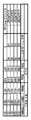
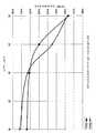
도 2는 실드 시험의 시험 결과를 나타낸 표이며, 도 3은 실드 시험의 시험 결과를 나타낸 도면이다. 이 실드 시험에서는 권회대층(14)을 권회하는 소정 각도 (θ)를 변화시킨 4개의 동축 케이블(1)을 길이 3m로 조정해서 시험용 케이블(A∼D)로 하고 이 시험용 케이블(A∼D)에 삽입한 신호가 시험용 케이블(A∼D)의 외부에 누설되는 양을 RF(Radio Frequency) 네트워크 애널라이저를 사용하여 검출하는 흡수 클램프법이라고 하는 방법으로 행했다. 또한, 삽입한 신호는 0㎐로부터 1㎓까지 순차 변화시키고, 그동안의 실드 효과의 변화를 측정했다. 또한, 비교를 위해 종래 사용되어 있었던 편조 타입 동축 케이블에도 마찬가지로 시험을 행했다.2 is a table showing the test results of the shield test, Figure 3 is a view showing the test results of the shield test. In this shield test, four
이 실드 시험에서 사용한 4개의 시험용 케이블(A∼D)의 구성은 외경 0.102㎜의 은도금 연동선을 7개 합쳐 꼬아서 중심 도체(11)를 형성하고, 이 중심 도체(11)의 외주에 FEP를 피복해서 외경 0.9㎜가 되도록 유전체층(12)을 형성하고, 이 유전체층(12)의 외주에 도체 소선(13a)에 맞는 외경 0.102㎜의 주석 도금 연동선을 29개, 동축 케이블의 길이 축방향에 대하여 9.6°의 각도를 주어서 횡권하여 외부 도체층(13)을 형성하고, 이 외부 도체층(13)의 외주에 두께 10㎛의 알루미늄 박과 두께 12㎛의 PET를 두께 2∼3㎛의 PVC을 통해 적층해서 이루어진 ALPET(14a)를 나선상으로 권회하여 권회대층(14)을 형성하고, 이 권회대층(14)의 외주가 두께 0.12㎜의 FEP로 이루어진 재킷(15)을 압출 피복해서 형성한 것이며, 이 시험용 케이블(A∼D)의 외경은 1,37㎜로 되어 있다.The configuration of the four test cables A to D used in this shield test is a combination of seven silver-plated copper wires having an outer diameter of 0.102 mm to form a
또한, 종래의 편조 타입 동축 케이블의 구성은 외형 0.102㎜의 은도금 연동선을 7개 합쳐 꼬아서 중심 도체를 형성하고, 이 중심 도체의 외주에 FEP를 피복해서 외경 0.88㎜이 되도록 유전체층을 형성하고, 이 유전체층의 외주에 외경 0.05㎜의 주석 도금 연동선을 이용해서 타수 16, 지수 6의 편조 구조로 외부 도체층을 형 성하고, 이 외부 도체층의 외주에 두께 0.12㎜의 FEP로 이루어진 재킷을 압출 피복해서 형성한 것이며, 이 종래의 편조 타입 동축 케이블의 외경은 1,37㎜로 되어 있다.In addition, the conventional braided coaxial cable has a center conductor formed by twisting seven silver-plated copper wires having an outer shape of 0.102 mm and forming a dielectric layer to cover the outer circumference of the center conductor so that the outer diameter is 0.88 mm. An outer conductor layer is formed on the outer circumference of the dielectric layer with a braided structure having a stroke number of 16 and an index of 6 using a tin-plated interlocking wire having an outer diameter of 0.05 mm. The outer diameter of this conventional braided type coaxial cable is 1,37 mm.
그리고, 시험용 케이블(A∼D)은 권회대층(14)을 권회하는 각도(θ)를 각각 변경하고 있고, 시험용 케이블(A)은 권회대층(14)을 동축 케이블(1)의 길이 축방향에 대하여 20°, 시험용 케이블(B)은 권회대층(14)을 동축 케이블(1)의 길이 축방향에 대하여 25°, 시험용 케이블(C)은 권회대층(14)을 동축 케이블(1)의 길이 축방향에 대하여 30°, 시험용 케이블(D)은 권회대층(14)을 동축 케이블(1)의 길이 축방향에 대하여 40°의 각도로 각각 나선상으로 권회되어 있다.The test cables A to D each change the angle θ of winding the wound
도 2, 도 3으로부터 명확한 바와 같이, 본 실시형태의 동축 케이블(1)의 특징적인 구성을 갖는 시험용 케이블(A∼D)은 편조 타입 동축 케이블에 비해 전체적으로 실드 효과가 높은 것으로 판명된다. 또한, 시험용 케이블(A∼D)을 비교하면, 시험용 케이블(A)은 신호가 10㎒일 때의 실드 효과는 -51.7㏈, 신호가 100㎒일 때의 실드 효과는 -48.5㏈이며, 시험용 케이블(B)은 신호가 10㎒일 때의 실드 효과는 -52.5㏈, 신호가 100㎒일 때의 실드 효과는 -49.8㏈이며, 시험용 케이블(C)은 신호가 10㎒일 때의 실드 효과는 -53.4㏈, 신호가 100㎒일 때의 실드 효과는 -50.0㏈이며, 시험용 케이블(D)은 신호가 10㎒일 때의 실드 효과는 -55.1㏈, 신호가 100㎒일 때의 실드 효과는 -51.1㏈이다.As apparent from Figs. 2 and 3, the test cables A to D having the characteristic constitution of the
따라서, 본 실시형태의 동축 케이블(1)은 종래의 동축 케이블과 비교해서 높은 실드 효과를 구비하고 있고, 또한 권회대층(14)을 권회하는 각도(θ)가 큰쪽이 보다 높은 실드 효과가 얻어지는 것으로 판명된다. 즉, 실드 시험의 결과에서는 권회대층(14)을 권회하는 각도(θ)는 20° 이상이 바람직하다고 할 수 있다. 단, 권회하는 각도(θ)가 커지면, 권회대층(14)의 ALPET(14a)의 폭이 각도(θ)에 반비례해서 좁아지기 때문에 동축 케이블(1)의 생산성이 저하된다. 따라서, 권회대층(14)을 권회하는 각도(θ)는 생산성을 고려하면 50°가 상한이 된다. 따라서, 실드 시험에서는 권회대층(14)을 권회하는 각도(θ)는 20° 이상 50° 이하가 바람직한 각도가 된다. 이어서, 권회 시험에 대해서 도 4∼도 10을 이용하여 상세히 설명한다.Therefore, the
도 4는 권회 시험의 시험법을 설명하기 위한 도면이다. 우선, 도 4를 이용하여 권회 시험의 시험 방법에 대해서 설명한다. 권회 시험은 시험용 케이블을 외경 10㎜의 파이프(20)에 10㎜의 간격을 형성하도록 해서 12회 권회하고, 이 권회한 시험용 케이블에 5㎓와 6㎓의 2종류의 신호를 삽입해서 신호의 감쇠량을 측정한 것이다.It is a figure for demonstrating the test method of the winding test. First, the test method of the winding test is demonstrated using FIG. In the winding test, the test cable was wound 12 times so that a 10 mm gap was formed in the
이 권회 시험에서는 도 2, 도 3에서 설명한 실드 시험과 동일한 시험용 케이블(A∼D)을 사용한 시험과, 실드 시험과는 다른 시험용 케이블(F∼H)을 사용한 시험의 2종류의 권회 시험을 행했다. 우선, 실드 시험과 동일한 시험용 케이블(A∼D)을 사용한 시험의 결과에 대해서 도 5∼도 7을 이용하여 설명한다.In this winding test, two types of winding tests were performed: a test using the same test cables A to D as the shield test described in FIGS. 2 and 3, and a test using the test cables F to H different from the shield test. . First, the result of the test using the test cables A-D similar to the shield test will be described with reference to FIGS. 5 to 7.
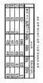
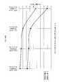
도 5는 권회 시험의 시험 결과를 나타낸 표, 도 6은 권회 시험의 감쇠량과 권회대층(14)의 권회 각도(θ)의 관계를 나타낸 도면, 도 7은 권회 시험의 감쇠량의 변동값과 권회대층(14)의 권회 각도(θ)의 관계를 나타낸 도면이다. 또한, 이 권회 시험에서는 비교를 위해 종래 사용되어 있었던 편조 타입 동축 케이블에도 마 찬가지 시험을 행했다.Fig. 5 is a table showing the test results of the winding test, Fig. 6 is a diagram showing the relationship between the amount of attenuation of the winding test and the winding angle θ of the winding
도 5로부터 명확한 바와 같이, 편조 타입 동축 케이블의 감쇠량이 5㎓시에 3.67㏈/m, 6㎓시에 4.03㏈/m인 것에 대해, 본 실시형태의 동축 케이블(1)의 특징적인 구성을 갖는 시험용 케이블(A∼D)에서는 시험용 케이블(A)의 감쇠량은 5㎓시에 3.360㏈/m, 6㎓시에 3.692㏈/m이며, 시험용 케이블(B)의 감쇠량은 5㎓시에 3.305㏈/m, 6㎓시에 3.626㏈/m이며, 시험용 케이블(C)의 감쇠량은 5㎓시에 3.233㏈/m, 6㎓시에 3.554㏈/m이며, 시험용 케이블(D)의 감쇠량은 5㎓시에 3.192㏈/m, 6㎓시에 3.510㏈/m이다. 따라서, 본 실시형태의 동축 케이블(1)의 특징적인 구성을 갖는 시험용 케이블(A∼D)은 편조 타입 동축 케이블에 비해 전체적으로 감쇠량이 저감하고 있는 것으로 판명된다.As apparent from Fig. 5, the attenuation amount of the braided coaxial cable has a characteristic configuration of the
또한, 도 5∼도 7로부터 명확한 바와 같이, 시험용 케이블(A∼D) 중에서는 권회대층(14)을 동축 케이블의 길이 축방향에 대하여 40°로 나선상으로 권회하고 있는 시험용 케이블(D)이 감쇠량 및 감쇠량 변동의 값이 가장 작아지고 있고, 시험용 케이블(A)과 시험용 케이블(D)에서는 감쇠량에 약 0.2㏈/m의 차이가 발생한다. 따라서, 본 실시형태의 동축 케이블(1)은 종래의 동축 케이블과 비교해서 감쇠량이 저감하고 있고, 또한 권회대층(14)을 권회하는 각도(θ)를 크게 하면 감쇠량이 보다 저감하는 것으로 판명된다.5 to 7, the amount of attenuation of the test cable D spirally wound around the winding
또한, 시험용 케이블(C)의 감쇠량과 시험용 케이블(D)의 감쇠량의 차이는 약0.04㏈/m로 그 차이가 작아지고 있고, 감쇠량 변동은 6㎓시에서는 대부분 차이가 없어져 있다. 이것으로부터 감쇠량의 저감은 권회대층(14)을 권회하는 각도(θ)가 30°를 초과하면 감쇠량의 변화가 거의 보합세를 이루게 되므로 이 30°를 경계로 어느 정도 더이상 오르지 않는 것으로 판명된다. 따라서, 권회대층(14)을 권회하는 각도(θ)가 40° 이상이어도 감쇠량의 값은 크게 변화되지 않고, 양호한 상태를 유지할 수 있는 것으로 사료된다. 그리고, 실드 시험의 결과에서도 언급한 바와 같이, 권회대층(14)을 권회하는 각도(θ)는 생산성을 고려하면 50°가 상한이 된다.The difference between the attenuation amount of the test cable C and the attenuation amount of the test cable D is about 0.04 dB / m, and the difference is small, and the attenuation amount variation is almost no difference at 6 Hz. From this, it is found that the reduction in the amount of attenuation does not increase any more around this 30 ° because the change in the amount of damping is almost flat when the angle? Of the winding of the winding
또한, 본 실시형태의 동축 케이블(1)에서는, 도 5∼도 7로부터 판명된 바와 같이, 감쇠량이 종래의 것에 비해서 대폭 향상됨과 아울러 그 변동량이 작아지는 권회대층(14)의 권회하는 각도(θ)는 약 25°가 된다.Moreover, in the
이상, 이 감쇠량 시험의 결과에서 권회대층(14)을 권회하는 각도(θ)는 하한이 25°가 되고, 50°가 상한이 된다. 그리고, 감쇠량과 생산성을 고려했을 경우, 감쇠량의 변화가 거의 보합세가 되고 있는 30° 이상 40° 이하가 권회대층(14)을 권회하는 가장 바람직한 각도라고 할 수 있다. 이어서, 다른 시험용 케이블을 이용한 권회 시험에 대해서 도 8∼도 10을 이용하여 상세히 설명한다.As mentioned above, as for the angle (theta) which wound the winding
도 8은 다른 시험용 케이블(F∼H)을 이용한 권회 시험의 시험 결과를 나타낸 표, 도 9는 다른 시험용 케이블(F∼H)을 이용한 권회 시험의 감쇠량과 권회대층(14)의 권회 각도(θ)의 관계를 나타낸 도면, 도 10은 다른 시험용 케이블(F∼H)을 이용한 권회 시험의 감쇠량의 변동값과 권회대층(14)의 권회 각도(θ)의 관계를 나타낸 도면이다.Fig. 8 is a table showing the test results of the winding test using different test cables F to H, and Fig. 9 is the attenuation amount of the winding test using the different test cables F to H and the winding angle θ of the winding
이 권회 시험에서 사용한 3개의 시험용 케이블(F∼H)의 구성은 외경 0.079㎜의 은도금 연동선을 7개 합쳐 꼬아서 중심 도체(11)를 형성하고, 이 중심 도체(11) 의 외주에 FEP를 피복해서 외경 0.7㎜이 되도록 유전체층(12)을 형성하고, 이 유전체층(12)의 외주에 도체 소선(13a)에 맞는 외경 0.05㎜의 주석 도금 연동선을 91개, 동축 케이블의 길이 축방향에 대하여 8.3°의 각도를 주어서 2중 횡권하여 외부 도체층(13)을 형성하고, 이 외부 도체층(13)의 외주에 두께 10㎛의 알루미늄 박과 두께 12㎛의 PET를 두께 2∼3㎛의 PVC을 통해 적층해서 이루어진 ALPET(14a)를 나선상으로 권회하여 권회대층(14)을 형성하고, 이 권회대층(14)의 외주에 두께 0.12m의 FEP로 이루어진 재킷(15)을 압출 피복해서 형성한 것이며, 이 시험용 케이블(F∼H)의 외경은 1,13㎜로 되어 있다.In the configuration of the three test cables F to H used in this winding test, the silver conductors of 0.079 mm in diameter are combined together to form a
그리고, 시험용 케이블(F∼H)은 권회대층(14)을 권회하는 각도(θ)를 각각 변경하고 있고, 시험용 케이블(F)은 권회대층(14)을 동축 케이블의 길이 축방향에 대하여 19°, 시험용 케이블(G)은 권회대층(14)을 동축 케이블의 길이 축방향에 대하여 25°, 시험용 케이블(H)은 권회대층(14)을 동축 케이블의 길이 축방향에 대하여 32°의 각도로 각각 나선상으로 권회되어 있다. 또한, 이 감쇠량 시험에서 사용된 비교 시험용 케이블(E)은 시험용 케이블(F∼H)에 권회대층(14)이 구비되어 있지 않은 것이다.The test cables F to H each change the angle θ of winding the wound
도 8로부터 명확한 바와 같이, 비교 시험용 케이블(E)의 감쇠량이 5㎓시에 4.940㏈/m, 6㎓시에 5.58㏈/m인 것에 대해, 본 실시형태의 동축 케이블(1)의 특징적인 구성을 갖는 시험용 케이블(F∼H)에서는 시험용 케이블(F)의 감쇠량은 5㎓시에 4.21㏈/m, 6㎓시에 4.65㏈/m이며, 시험용 케이블(G)의 감쇠량은 5㎓시에 4.11㏈/m, 6㎓시에 4.53㏈/m이며, 시험용 케이블(H)의 감쇠량은 5㎓시에 4.05㏈/m, 6㎓시 에 4.45㏈/m이다. 따라서, 본 실시형태의 동축 케이블(1)의 특징적인 구성을 갖는 시험용 케이블(F∼H)은 비교 시험용 케이블(E)에 비해 전체적으로 감쇠량이 저감하고 있는 것으로 판명된다.As apparent from Fig. 8, the characteristic configuration of the
또한, 도 8∼도 10로부터 명확한 바와 같이, 시험용 케이블(F∼H) 중에서는 권회대층(14)을 동축 케이블의 길이 축방향에 대하여 32°로 나선상으로 권회하고 있는 시험용 케이블(H)이 감쇠량 및 감쇠량 변동의 값이 가장 작게 되어 있고, 시험용 케이블(F)과 시험용 케이블(H)에서는 감쇠량에 약 0.2㏈/m의 차이가 발생한다. 따라서, 본 실시형태의 동축 케이블(1)은 종래의 동축 케이블과 비교해서 감쇠량이 저감하고 있고, 또한 외부 도체층(13)을 2중 횡권했을 경우에도 권회대층(14)을 권회하는 각도(θ)를 크게 하면 감쇠량이 보다 저감하는 것으로 판명된다.8 to 10, the amount of attenuation of the test cable H, in which the winding
또한, 시험용 케이블(G)의 감쇠량과 시험용 케이블(H)의 감쇠량의 차이는 약 0.06㏈/m로 그 차이가 작아지고 있고, 감쇠량 변동은 시험용 케이블(G)과 시험용 케이블(H) 사이에서 대부분 차이가 없게 되어 있다. 이것으로부터 감쇠량의 저감은 권회대층(14)을 권회하는 각도(θ)가 25∼32°의 사이, 환언하면 약 30°에서 감쇠량의 변화가 거의 보합세를 이루게 되므로 약 30°에서 어느 정도 한계점이 되는 것으로 판명된다. 따라서, 권회대층(14)을 권회하는 각도(θ)가 32°이상이어도 감쇠량의 값은 크게 변화되지 않고, 양호한 상태를 유지할 수 있는 것으로 사료된다. 그리고, 실드 시험의 결과에서도 언급한 바와 같이, 권회대층(14)을 권회하는 각도(θ)는 생산성을 고려하면 50°가 상한이 된다.In addition, the difference between the attenuation of the test cable G and the attenuation of the test cable H is about 0.06 dB / m, and the difference is small, and the attenuation fluctuation is mostly between the test cable G and the test cable H. There is no difference. From this, the reduction of the attenuation becomes a certain limit at about 30 ° because the change in the attenuation is almost flat at about 30 ° while the angle θ of winding the winding
또한, 본 실시형태의 동축 케이블(1)에서는 외부 도체층이 2중 횡권인 경우, 도 8∼도 10로부터 판명된 바와 같이, 감쇠량이 종래의 것에 비해서 대폭 향상됨과 아울러 그 변동량이 작아지는 권회대층(14)의 권회하는 각도(θ)는 약 25°가 된다.Moreover, in the
이상, 이 감쇠량 시험의 결과에서 권회대층(14)을 권회하는 각도(θ)는 하한은 25°가 되고, 50°가 상한이 된다. 그리고, 감쇠량과 생산성을 고려했을 경우 감쇠량의 변화가 거의 보합세를 이루게 되는 30° 이상 40° 이하가 권회대층(14)을 권회하는 가장 바람직한 각도라고 할 수 있다.As mentioned above, the angle (theta) which wound the winding
이상, 3종류의 시험 결과에서 권회대층(14)을 권회하는 소정 각도(θ)의 범위는 요청되는 감쇠량의 값으로부터 하한이 25°, 생산성의 관점에서 상한이 50°가 된다. 그리고, 바람직한 범위로서는 30° 이상 40° 이하가 권회대층(14)을 권회하는 가장 바람직한 각도라고 할 수 있다.As mentioned above, the range of the predetermined angle (theta) which winds up the winding-
이상, 상술한 본 실시형태의 동축 케이블(1)은 외부 도체층(13)이 도체 소선(13a)에 의해 횡권 형성되어 있으므로 가요성이 풍부함과 아울러 종래의 동축 케이블과 비교해서 높은 실드 효과를 구비하고 있고, 또한 감쇠량도 저감하고 있는 것으로 판명된다. 그리고, 권회대층(14)을 권회하는 각도(θ)를 크게 함으로써 실드 효과가 보다 향상되고, 감쇠량이 보다 저감하는 것으로 판명된다. 이것은 권회대층(14)을 권회하는 각도(θ)를 크게 하면 그 만큼 권회대층(14)에 의한 외부 도체층(13)을 조이는 힘이 강해지기 때문에 외부 도체층(13)의 도체 소선(13a)끼리의 밀착도가 그 만큼 향상되기 때문이다. 도체 소선(13a)끼리의 밀착도가 향상되면 도체 소선(13a)끼리의 사이에 간극이 발생하기 어려워진다. 따라서, 도체 소선(13a) 끼리의 사이에 간극이 발생함으로 인한 실드 효과의 저감을 방지하는 것이 가능해 지고, 실드 효과가 향상한다. 또한, 이 권회대층(14)은 ALPET(14a)에 의해 형성되어 있기 때문에 이 권회대층(14) 자체도 실드로서 작용하게 된다.As described above, the
이에 따라, 본 실시형태의 동축 케이블(1)은 외부 도체층(13)과, 권회대층(14)의 2개의 실드 효과를 갖는 층을 구비하게 되고, 또한 외부 도체층(13)의 도체 소선(13a)이 권회대층(14)에 의해 조여지게 되므로 도체 소선(13a)끼리의 밀착도를 향상시켜서 더욱 그 밀착 상태가 유지되게 되고, 외부 도체층(13)의 실드 효과를 보다 높이는 것이 가능하게 되고, 또한 감쇠량의 저감을 도모할 수도 있다.Therefore, the
한편, 본 실시형태에서는 권회대층(14)은 금속화 테이프인 ALPET(14a)에 의해 형성되어 있었지만 본 발명의 권회대층은 이것에 한정되는 것이 아니다. 예를 들면, 외부 도체층을 조이는 것이 가능하면 어떤 것이라도 상관없다.In addition, in this embodiment, although the winding
본 발명의 동축 케이블은 어떤 기기라도 적용 가능하다. 예를 들면, 컴퓨터, 계산기, 휴대전화 등의 전자기기라도 적용 가능하고, 또한 자동차, 비행기 등의 제어 기기를 협소부에 탑재할 필요가 있는 기계의 제어 회로에도 적용 가능하다.The coaxial cable of the present invention can be applied to any device. For example, it is applicable to electronic devices, such as a computer, a calculator, and a mobile telephone, and also it is applicable to the control circuit of the machine which needs to mount control devices, such as an automobile and an airplane, in a narrow part.
Claims (5)
Translated fromKoreanApplications Claiming Priority (3)
| Application Number | Priority Date | Filing Date | Title |
|---|---|---|---|
| JP2007006320AJP2008171778A (en) | 2007-01-15 | 2007-01-15 | Coaxial cable |
| JPJP-P-2007-006320 | 2007-01-15 | ||
| PCT/JP2008/050310WO2008087919A1 (en) | 2007-01-15 | 2008-01-08 | Coaxial cable |
Publications (1)
| Publication Number | Publication Date |
|---|---|
| KR20090105922Atrue KR20090105922A (en) | 2009-10-07 |
Family
ID=39635923
Family Applications (1)
| Application Number | Title | Priority Date | Filing Date |
|---|---|---|---|
| KR1020097013781AWithdrawnKR20090105922A (en) | 2007-01-15 | 2008-01-08 | Coaxial cable |
Country Status (5)
| Country | Link |
|---|---|
| JP (1) | JP2008171778A (en) |
| KR (1) | KR20090105922A (en) |
| CN (1) | CN101601104A (en) |
| TW (1) | TW200837778A (en) |
| WO (1) | WO2008087919A1 (en) |
Cited By (1)
| Publication number | Priority date | Publication date | Assignee | Title |
|---|---|---|---|---|
| WO2024117806A1 (en)* | 2022-11-30 | 2024-06-06 | 엘에스전선 주식회사 | Submarine cable having shielding layer that considers dynamic characteristics |
Families Citing this family (7)
| Publication number | Priority date | Publication date | Assignee | Title |
|---|---|---|---|---|
| JP5315815B2 (en)* | 2008-06-25 | 2013-10-16 | 住友電気工業株式会社 | Thin coaxial cable |
| JP5309734B2 (en)* | 2008-07-02 | 2013-10-09 | 株式会社オートネットワーク技術研究所 | coaxial cable |
| JP5351642B2 (en)* | 2009-02-27 | 2013-11-27 | 日立電線株式会社 | cable |
| CN102339662B (en)* | 2010-07-16 | 2013-12-25 | 住友电气工业株式会社 | Twisted-pair cable and method for manufacturing same |
| DE102012204554A1 (en)* | 2012-03-21 | 2013-09-26 | Leoni Kabel Holding Gmbh | Signal cable and method for high-frequency signal transmission |
| US10043599B2 (en)* | 2015-04-24 | 2018-08-07 | Sumitomo Electric Industries, Ltd. | Multi-core cable |
| CN109448897B (en)* | 2018-10-09 | 2020-04-24 | 江阴凯博通信科技有限公司 | Bending fatigue resistant coaxial cable and production process thereof |
Family Cites Families (8)
| Publication number | Priority date | Publication date | Assignee | Title |
|---|---|---|---|---|
| JPH0741053Y2 (en)* | 1990-06-22 | 1995-09-20 | 日立電線株式会社 | Multi-core shielded cable |
| JP3299172B2 (en)* | 1998-02-17 | 2002-07-08 | 株式会社オーディオテクニカ | Communication cable |
| JP2000057863A (en)* | 1998-08-11 | 2000-02-25 | Junkosha Co Ltd | Coaxial cable |
| JP3606141B2 (en)* | 1999-04-05 | 2005-01-05 | 住友電気工業株式会社 | Coaxial strand, coaxial cable, and electronic equipment using the same |
| EP1267362B1 (en)* | 2001-06-15 | 2004-10-13 | Nexans | Transmission cable for electrical signals |
| JP3900864B2 (en)* | 2001-07-05 | 2007-04-04 | 日立電線株式会社 | 2-core parallel micro coaxial cable |
| JP3678179B2 (en)* | 2001-07-25 | 2005-08-03 | 日立電線株式会社 | Double horizontal winding 2-core parallel micro coaxial cable |
| JP3738774B2 (en)* | 2004-04-15 | 2006-01-25 | 住友電気工業株式会社 | Shielded wire |
- 2007
- 2007-01-15JPJP2007006320Apatent/JP2008171778A/enactivePending
- 2007-12-19TWTW096148630Apatent/TW200837778A/enunknown
- 2008
- 2008-01-08CNCNA2008800021782Apatent/CN101601104A/enactivePending
- 2008-01-08KRKR1020097013781Apatent/KR20090105922A/ennot_activeWithdrawn
- 2008-01-08WOPCT/JP2008/050310patent/WO2008087919A1/enactiveApplication Filing
Cited By (1)
| Publication number | Priority date | Publication date | Assignee | Title |
|---|---|---|---|---|
| WO2024117806A1 (en)* | 2022-11-30 | 2024-06-06 | 엘에스전선 주식회사 | Submarine cable having shielding layer that considers dynamic characteristics |
Also Published As
| Publication number | Publication date |
|---|---|
| TW200837778A (en) | 2008-09-16 |
| CN101601104A (en) | 2009-12-09 |
| JP2008171778A (en) | 2008-07-24 |
| WO2008087919A1 (en) | 2008-07-24 |
Similar Documents
| Publication | Publication Date | Title |
|---|---|---|
| US6677534B2 (en) | Double-laterally-wound two-core parallel extrafine coaxial cable | |
| US10763012B2 (en) | Shielded cable | |
| US8026441B2 (en) | Coaxial cable shielding | |
| KR20090105922A (en) | Coaxial cable | |
| CN106067347B (en) | Multi-core cable | |
| US20180108455A1 (en) | Parallel pair cable | |
| JP3900864B2 (en) | 2-core parallel micro coaxial cable | |
| JP5330888B2 (en) | High-speed differential cable | |
| KR20140001728A (en) | Insulated wire, coaxial cable and multiconductor cable | |
| CN110675978A (en) | A microwave low-loss phase-stable cable | |
| JP2021028898A (en) | Small diameter coaxial cable excellent in flexibility | |
| JP2008293729A (en) | Coaxial cable | |
| JP7340384B2 (en) | Small diameter coaxial cable with excellent flexibility | |
| US12112861B2 (en) | Coaxial cable | |
| JP5314821B2 (en) | coaxial cable | |
| JP2010073463A (en) | High-speed differential cable | |
| JP2003031046A (en) | 2-core parallel micro coaxial cable with vertical deposition tape | |
| JP2003031045A (en) | 2-core parallel micro coaxial cable with vertical deposition tape | |
| JP2004119240A (en) | Flexible high frequency coaxial cable | |
| JP2021099973A (en) | Multicore communication cable | |
| WO2022130801A1 (en) | Multicore parallel cable and method for manufacturing same | |
| JP7353039B2 (en) | Coaxial cable with excellent bending phase stability | |
| WO2022209876A1 (en) | Coaxial cable | |
| JP2022170784A (en) | 2-core parallel coaxial cable | |
| JP2024148544A (en) | Composite Cable |
Legal Events
| Date | Code | Title | Description |
|---|---|---|---|
| PA0105 | International application | Patent event date:20090701 Patent event code:PA01051R01D Comment text:International Patent Application | |
| PG1501 | Laying open of application | ||
| PC1203 | Withdrawal of no request for examination | ||
| WITN | Application deemed withdrawn, e.g. because no request for examination was filed or no examination fee was paid |