KR20090078784A - Trans connector - Google Patents
Trans connectorDownload PDFInfo
- Publication number
- KR20090078784A KR20090078784AKR1020097006553AKR20097006553AKR20090078784AKR 20090078784 AKR20090078784 AKR 20090078784AKR 1020097006553 AKR1020097006553 AKR 1020097006553AKR 20097006553 AKR20097006553 AKR 20097006553AKR 20090078784 AKR20090078784 AKR 20090078784A
- Authority
- KR
- South Korea
- Prior art keywords
- bone fixation
- bridge member
- bone
- locking
- elements
- Prior art date
- Legal status (The legal status is an assumption and is not a legal conclusion. Google has not performed a legal analysis and makes no representation as to the accuracy of the status listed.)
- Granted
Links
Images


Classifications
- A—HUMAN NECESSITIES
- A61—MEDICAL OR VETERINARY SCIENCE; HYGIENE
- A61B—DIAGNOSIS; SURGERY; IDENTIFICATION
- A61B17/00—Surgical instruments, devices or methods
- A61B17/56—Surgical instruments or methods for treatment of bones or joints; Devices specially adapted therefor
- A61B17/58—Surgical instruments or methods for treatment of bones or joints; Devices specially adapted therefor for osteosynthesis, e.g. bone plates, screws or setting implements
- A61B17/68—Internal fixation devices, including fasteners and spinal fixators, even if a part thereof projects from the skin
- A61B17/70—Spinal positioners or stabilisers, e.g. stabilisers comprising fluid filler in an implant
- A61B17/7049—Connectors, not bearing on the vertebrae, for linking longitudinal elements together
- A—HUMAN NECESSITIES
- A61—MEDICAL OR VETERINARY SCIENCE; HYGIENE
- A61B—DIAGNOSIS; SURGERY; IDENTIFICATION
- A61B17/00—Surgical instruments, devices or methods
- A61B17/56—Surgical instruments or methods for treatment of bones or joints; Devices specially adapted therefor
- A61B17/58—Surgical instruments or methods for treatment of bones or joints; Devices specially adapted therefor for osteosynthesis, e.g. bone plates, screws or setting implements
- A61B17/68—Internal fixation devices, including fasteners and spinal fixators, even if a part thereof projects from the skin
- A61B17/70—Spinal positioners or stabilisers, e.g. stabilisers comprising fluid filler in an implant
- A61B17/7049—Connectors, not bearing on the vertebrae, for linking longitudinal elements together
- A61B17/7052—Connectors, not bearing on the vertebrae, for linking longitudinal elements together of variable angle or length
- A—HUMAN NECESSITIES
- A61—MEDICAL OR VETERINARY SCIENCE; HYGIENE
- A61B—DIAGNOSIS; SURGERY; IDENTIFICATION
- A61B17/00—Surgical instruments, devices or methods
- A61B17/56—Surgical instruments or methods for treatment of bones or joints; Devices specially adapted therefor
- A61B17/58—Surgical instruments or methods for treatment of bones or joints; Devices specially adapted therefor for osteosynthesis, e.g. bone plates, screws or setting implements
- A61B17/68—Internal fixation devices, including fasteners and spinal fixators, even if a part thereof projects from the skin
- A61B17/82—Internal fixation devices, including fasteners and spinal fixators, even if a part thereof projects from the skin for bone cerclage
- A—HUMAN NECESSITIES
- A61—MEDICAL OR VETERINARY SCIENCE; HYGIENE
- A61B—DIAGNOSIS; SURGERY; IDENTIFICATION
- A61B17/00—Surgical instruments, devices or methods
- A61B17/56—Surgical instruments or methods for treatment of bones or joints; Devices specially adapted therefor
- A61B17/58—Surgical instruments or methods for treatment of bones or joints; Devices specially adapted therefor for osteosynthesis, e.g. bone plates, screws or setting implements
- A61B17/68—Internal fixation devices, including fasteners and spinal fixators, even if a part thereof projects from the skin
- A61B17/84—Fasteners therefor or fasteners being internal fixation devices
- A61B17/86—Pins or screws or threaded wires; nuts therefor
- A—HUMAN NECESSITIES
- A61—MEDICAL OR VETERINARY SCIENCE; HYGIENE
- A61F—FILTERS IMPLANTABLE INTO BLOOD VESSELS; PROSTHESES; DEVICES PROVIDING PATENCY TO, OR PREVENTING COLLAPSING OF, TUBULAR STRUCTURES OF THE BODY, e.g. STENTS; ORTHOPAEDIC, NURSING OR CONTRACEPTIVE DEVICES; FOMENTATION; TREATMENT OR PROTECTION OF EYES OR EARS; BANDAGES, DRESSINGS OR ABSORBENT PADS; FIRST-AID KITS
- A61F2/00—Filters implantable into blood vessels; Prostheses, i.e. artificial substitutes or replacements for parts of the body; Appliances for connecting them with the body; Devices providing patency to, or preventing collapsing of, tubular structures of the body, e.g. stents
- A61F2/02—Prostheses implantable into the body
- A61F2/30—Joints
- A61F2/44—Joints for the spine, e.g. vertebrae, spinal discs
- A—HUMAN NECESSITIES
- A61—MEDICAL OR VETERINARY SCIENCE; HYGIENE
- A61B—DIAGNOSIS; SURGERY; IDENTIFICATION
- A61B17/00—Surgical instruments, devices or methods
- A61B17/56—Surgical instruments or methods for treatment of bones or joints; Devices specially adapted therefor
- A61B17/58—Surgical instruments or methods for treatment of bones or joints; Devices specially adapted therefor for osteosynthesis, e.g. bone plates, screws or setting implements
- A61B17/68—Internal fixation devices, including fasteners and spinal fixators, even if a part thereof projects from the skin
- A61B17/70—Spinal positioners or stabilisers, e.g. stabilisers comprising fluid filler in an implant
- A61B17/7001—Screws or hooks combined with longitudinal elements which do not contact vertebrae
- A61B17/7032—Screws or hooks with U-shaped head or back through which longitudinal rods pass
- A—HUMAN NECESSITIES
- A61—MEDICAL OR VETERINARY SCIENCE; HYGIENE
- A61B—DIAGNOSIS; SURGERY; IDENTIFICATION
- A61B17/00—Surgical instruments, devices or methods
- A61B17/56—Surgical instruments or methods for treatment of bones or joints; Devices specially adapted therefor
- A61B17/58—Surgical instruments or methods for treatment of bones or joints; Devices specially adapted therefor for osteosynthesis, e.g. bone plates, screws or setting implements
- A61B17/68—Internal fixation devices, including fasteners and spinal fixators, even if a part thereof projects from the skin
- A61B17/70—Spinal positioners or stabilisers, e.g. stabilisers comprising fluid filler in an implant
- A61B17/7001—Screws or hooks combined with longitudinal elements which do not contact vertebrae
- A61B17/7035—Screws or hooks, wherein a rod-clamping part and a bone-anchoring part can pivot relative to each other
- A61B17/7037—Screws or hooks, wherein a rod-clamping part and a bone-anchoring part can pivot relative to each other wherein pivoting is blocked when the rod is clamped
Landscapes
- Health & Medical Sciences (AREA)
- Orthopedic Medicine & Surgery (AREA)
- Life Sciences & Earth Sciences (AREA)
- Surgery (AREA)
- Neurology (AREA)
- Biomedical Technology (AREA)
- Engineering & Computer Science (AREA)
- General Health & Medical Sciences (AREA)
- Heart & Thoracic Surgery (AREA)
- Animal Behavior & Ethology (AREA)
- Public Health (AREA)
- Veterinary Medicine (AREA)
- Medical Informatics (AREA)
- Molecular Biology (AREA)
- Nuclear Medicine, Radiotherapy & Molecular Imaging (AREA)
- Oral & Maxillofacial Surgery (AREA)
- Cardiology (AREA)
- Transplantation (AREA)
- Vascular Medicine (AREA)
- Surgical Instruments (AREA)
- Prostheses (AREA)
- Photoreceptors In Electrophotography (AREA)
- Discharging, Photosensitive Material Shape In Electrophotography (AREA)
- Lasers (AREA)
- Mechanical Coupling Of Light Guides (AREA)
- Feeding And Controlling Fuel (AREA)
Abstract
Translated fromKoreanDescription
Translated fromKorean본 출원은 인용에 의해 그 전체 내용이 본 명세서에 합체되는, 2006년 9월 26일자로 출원된 미국 특허 가출원 번호 60/827,016의 우선권을 주장한다.This application claims the priority of US Patent Provisional Application No. 60 / 827,016, filed September 26, 2006, the entire contents of which are hereby incorporated by reference.
본 발명은 척추 고정(spinal fixation)용 장치에 관한 것으로서, 보다 상세하게, 세로 척추 봉 (longitudinal spinal rods) 또는 다른 가늘고 긴 부재들을 연결하기 위한 트랜스컨넥터에 관한 것이다.The present invention relates to a device for spinal fixation, and more particularly, to a transconnector for connecting longitudinal spinal rods or other elongated members.
척추 융합(spinal fusion)은 척추뼈들(vertebra)의 서로에 대한 이동을 제한하기 위해 2개 또는 그 이상의 인접한 척추뼈를 척추 고정 장치로 결합하는 것과 관련된 시술이다. 여러가지 알려진 이유들에 의해, 척추 고정 장치들은 인접한 척추체들(vertebral bodies) 사이의 바람직한 관계를 정렬 및/또는 고정하는 척추 수술에 사용된다. 그러한 장치들은 전형적으로 예를 들어, 척추(vertebral column)의 가시 돌기(spinous processes)의 어느 하나의 측면의 후방 척추(posterior spine)에 길이 방향으로 배치된, 상대적으로 단단한 고정 봉(fixation rod), 동적이거나 유연한 척추 봉, 플레이트 등과 같은 한 쌍의 척추 고정 요소들을 포함한다. 척추 고정 요소들은 예를 들어, 후크, 볼트, 와이어, 스크류 등과 같은 다양한 뼈 고정 요소들에 척추 고정 요소를 부착함으로써 인접한 척추뼈에 연결된다. 뼈 고정 요소 들은 통상적으로 척추 고정 요소가 삽입된 후 클램핑되는 봉-수납 채널(rod-receiving channel)을 가진 본체부를 포함한다. 외과의사들은 통상적으로 주어진 척추 질환을 치료하기 위해, 다수의 뼈 고정 요소들뿐만 아니라 다수의 척추 고정 요소들의 설치를 선택할 수 있다. 척추 고정 요소들은 미리 결정된 외형(contour)을 가질 수 있으며, 일단 설치되면, 척추 고정 요소는 필요한 치료 또는 척추 융합이 달성되기까지 또는 어느 정도 긴 시간까지 필요한 공간적 관계로 척추뼈를 유지할 수 있다.Spinal fusion is a procedure involving joining two or more adjacent vertebrae into a spinal fixation device to limit the movement of the vertebrae to each other. For various known reasons, spinal fixation devices are used in spinal surgery to align and / or fix the desired relationship between adjacent vertebral bodies. Such devices are typically, for example, relatively rigid fixation rods, longitudinally disposed in the posterior spine of either side of the spinous processes of the vertebral column, And a pair of spinal fixation elements such as dynamic or flexible spinal rods, plates, and the like. Spinal fixation elements are connected to adjacent vertebrae, for example, by attaching the spinal fixation element to various bone fixation elements such as hooks, bolts, wires, screws, and the like. Bone fixation elements typically include a body portion having a rod-receiving channel that is clamped after the spinal fixation element is inserted. Surgeons typically choose to install multiple spinal fixation elements as well as multiple bone fixation elements to treat a given spinal disease. Spinal fixation elements may have a predetermined contour, and once installed, the spinal fixation element may maintain the vertebrae in the necessary spatial relationship until the required treatment or spinal fusion is achieved or for some time.
또한, 이중(dual) 척추 봉 조립체의 강도와 안정성은, 가늘고 긴 척추 봉들을 상호 연결하기 위해 척추 봉을 실질적으로 가로질러 확장하고 척추를 실질적으로 수평 방향으로 가로지르는 횡단-꺾쇠(corss-brace) 또는 트랜스컨넥터를 이용하여 두 개의 척추 봉들을 연결시킴에 의해 향상될 수 있다. 그러나, 트랜스컨넥터의 사용은 외과의사들에게 하나 또는 그 이상의 어려움을 제공할 수 있다. 트랜스컨넥터가 사용될 수 있는 가장 간단한 상황은, 두 개의 척추 봉들이 서로 실질적으로 평행한 경우, 즉 중간-측면(medial-lateral) 방향으로 봉의 수렴 또는 분기가 없어서, 두 개의 척추 봉들이 전방-후방(anterior-posterior) 방향에서 볼 때 관상 평면(coronal plane)에 대해 동일한 방위를 가지는, 즉 척추 봉들이 측면에서 볼 때 동일 평면이고, 두 개의 척추 봉들이 미리 정해진 간격으로 서로로부터 고정되게 위치될 때 발생한다. 그러나, 다양한 인자들 때문에, 두 개의 척추 봉들은 진료 상황에서 기하적으로 그렇게 잘 정렬되지는 않는다.In addition, the strength and stability of a dual spinal rod assembly extends substantially across the spinal rod and interconnects the vertebrae substantially horizontally to interconnect the elongated spinal rods. Or by connecting two spinal rods using a transconnector. However, the use of transconnectors can present one or more difficulties for surgeons. The simplest situation in which a transconnector can be used is that if the two vertebral rods are substantially parallel to each other, i.e. there is no convergence or branching of the rods in the medial-lateral direction, the two vertebral rods are forward-rear ( Occurs when the spinal rods are coplanar when viewed from the side in the anterior-posterior direction, i.e. the spinal rods are coplanar when viewed from the side, and the two vertebral rods are fixedly positioned from each other at predetermined intervals. do. However, due to various factors, the two spinal rods are not geometrically so well aligned in the clinical setting.
따라서, 척추 봉 정렬에 있어서, 다양한 변형들에 적응하기 위해 조절될 수 있는 트랜스컨넥터를 제공하는 것이 유용하다. 그러나, 그러한 조절성의 추가는 시술 환경에서 조립과 사용을 어렵게 할 수 있는 많은 부품을 트랜스컨넥터가 필요하게 할 수 있다.Thus, in spinal rod alignment, it is useful to provide a transconnector that can be adjusted to adapt to various variations. However, the addition of such control may require the transconnector to have many parts that can be difficult to assemble and use in the surgical environment.
더군다나, 트랜스컨넥터들이 인접한 척추 봉들에 위치될 때, 장치의 확장된 부분(extended profile)은 가끔씩 부드러운 조직의 외상을 유발시킬 수 있다. 따라서, 부드러운 조직에 대한 외상의 총 발생량을 가능한 줄이고, 이에 수반되는 합병증의 발병을 최소화하기 위해 작은 측면(즉, 횡단) 프로파일(profile)을 가진 트랜스컨넥터를 제공하는 것이 바람직하다. 또한, 작은 측면 프로파일을 가진 트랜스컨넥터를 제공하는 것은 이러 저러한 이유로 뼈 고정 요소들이 서로 가깝게 위치된 세로 방향 척추 봉들의 결합을 시도할 때 유용하다.Furthermore, when transconnectors are located in adjacent spinal rods, an extended profile of the device can sometimes cause trauma of soft tissue. Accordingly, it is desirable to provide a transconnector with a small lateral (ie transverse) profile to reduce the total incidence of trauma to soft tissues as much as possible and to minimize the onset of complications associated therewith. Also, providing a transconnector with a small lateral profile is useful for this reason when attempting to engage longitudinal spinal rods with bone fixation elements located close to each other.
또한, 일단 조립되면 트랜스컨넥터 조립체의 개별 조각들의 분리를 방지하여, 환자에 시술하는 동안 트랜스컨넥터의 갑작스런 분리 가능성을 줄임으로써 트랜스컨넥터의 시술을 용이하게 도울 수 있는 트랜스컨넥터를 제공하는 것이 바람직하다. 또한, 세로 척추 봉들에 대한 트랜스컨넥터의 위치 고정에 필요한 총 공정 수를 줄임으로써, 환자 이식을 위해 필요한 시간 및 노력을 절감하여 트랜스컨넥터의 시술을 용이하게 할 수 있는 트랜스컨넥터를 제공하는 것이 바람직하다.It is also desirable to provide a transconnector that, once assembled, prevents the separation of individual pieces of the transconnector assembly, thereby facilitating the procedure of the transconnector by reducing the likelihood of sudden disconnection of the transconnector during the procedure in a patient. In addition, it is desirable to provide a transconnector that can facilitate the operation of the transconnector by reducing the total number of processes required to secure the position of the transconnector to the longitudinal spinal rods, thereby reducing the time and effort required for patient implantation. .
따라서, 변화하는 척추 봉 정렬에 대해 유용하게 조절할 수 있고, 관련된 조직 외상을 줄이기 위해 감소된 측면 모양을 가지며, 환자에 시술시 선-조립(pre-assemble) 상태가 그대로 유지될 수 있는, 인접한 척추 봉들의 연결을 위한 개선된 트랜스컨넥터에 대한 필요가 존재한다.Thus, adjacent spine, which can be usefully adjusted for changing spinal rod alignment, has a reduced lateral shape to reduce associated tissue trauma, and can remain pre-assembled during the procedure in a patient. There is a need for an improved transconnector for connecting rods.
본 발명은 인접한 세로 척추 봉들의 연결을 위한 트랜스컨넥터에 관한 것으로서, 척추 봉들은 다수의 뼈 고정 요소들에 의해 환자의 척추뼈에 고정되어 있다. 뼈 고정 요소는 바람직하게 뼈 앵커(bone anchor) 및 본체부를 포함하고, 본체부는 봉-수납 채널 및 봉-수납 채널에 척추 봉을 고정하기 위하여 선택적인 밀폐 캡을 포함할 수 있다.The present invention relates to a transconnector for the connection of adjacent longitudinal spinal rods, wherein the spinal rods are secured to the vertebra of the patient by a plurality of bone anchoring elements. The bone fixation element preferably includes a bone anchor and a body portion, the body portion may include an optional closure cap for securing the spinal rod to the rod-containing channel and the rod-containing channel.
트랜스컨넥터는 브리지 부재와 제1 및 제2 뼈 고정 커플링 요소들을 포함할 수 있다. 브리지 부재는 제1 및 제2 끝단을 포함할 수 있다. 바람직하게, 제1 및 제2 뼈 고정 커플링 요소들은 (i) 브리지 부재의 제1 및 제2 끝단에 결합하고 (ii) 뼈 고정 요소들의 어느 하나에 결합하도록 구성된다.The transconnector may comprise a bridge member and first and second bone fixation coupling elements. The bridge member may include first and second ends. Preferably, the first and second bone fixation coupling elements are configured to (i) couple to the first and second ends of the bridge member and (ii) to either of the bone fixation elements.
바람직하게, 뼈 고정 커플링 요소들은 뼈 고정 요소들의 본체부에 결합하도록 구성된다. 하나의 예시적인 실시예에 있어서, 뼈 고정 커플링 요소들은 파스너를 포함할 수 있고, 파스너는 뼈 고정 요소와 결합하도록 구성된다. 예를 들어, 파스너는 뼈 고정 요소의 본체부에 형성된 다수의 나사산들과 나사 결합하도록 구성될 수 있다. 대안적으로, 파스너는 뼈 고정 요소의 선택적인 밀폐 캡에 형성된 내부 나사 구멍과 나사 결합하도록 구성될 수도 있다.Preferably, the bone fixation coupling elements are configured to engage the body portion of the bone fixation elements. In one exemplary embodiment, the bone fixation coupling elements may comprise a fastener, the fastener configured to engage the bone fixation element. For example, the fastener may be configured to screw into a plurality of threads formed in the body portion of the bone fixation element. Alternatively, the fastener may be configured to screw into an internal threaded hole formed in the optional closure cap of the bone fixation element.
다른 예시적인 실시예에 있어서, 뼈 고정 커플링 요소들은 뼈 고정 요소의 본체부의 외측 표면에 형성된 돌기 또는 리세스의 어느 하나와 결합하기 위해 그 위에 형성된 돌기 또는 리세스의 어느 하나를 포함할 수 있다. 대안적으로, 뼈 고정 커플링 요소들은 예를 들어, 간섭 고정, 가압-고정, 스냅-고정, 또는 텅(tongue) 또는 그루브 형태의 연결을 통해 뼈 고정 요소들의 본체부와 결합할 수 있다.In another exemplary embodiment, the bone fixation coupling elements may include any of the protrusions or recesses formed thereon to engage with any of the protrusions or recesses formed on the outer surface of the body portion of the bone fixation element. . Alternatively, the bone fixation coupling elements can engage with the body portion of the bone fixation elements, for example, via interference fixation, push-fix, snap-fix, or tongue or groove shaped connection.
하나의 예시적인 실시예에 있어서, 뼈 고정 커플링 요소들은 각각 록킹 캡, 부싱 및 너트를 포함할 수 있고, 부싱은 록킹 캡을 브리지 부재와 상호 연결하도록 구성되어 있다. 또한, 록킹 캡은 뼈 고정 요소와 결합하기 위한 제1 나사산 세트, 너트와 결합하기 위한 제2 나사산 세트, 및 제1 나사산 세트와 제2 나사산 세트 사이에 위치된 테이퍼진 중앙부를 포함할 수 있다. 부싱은 외측 표면과 중앙 통로를 포함할 수 있고, 중앙 통로는 록킹 캡의 테이퍼진 중앙부를 그 안에 수납하도록 구성된다. 뼈 고정 커플링 요소는 제1 위치와 제2 위치 사이에서 움직일 수 있고, 뼈 고정 요소가 제1 위치에 있을 때, 브리지 부재는 부싱에 의해 록킹 캡에 대해 각이 질 수 있으며, 뼈 고정 커플링 요소가 제2 위치에 있을 때, 브리지 부재는 록킹 캡에 대해 고정되게 확보될 수 있다. 바람직하게, 너트의 회전은 뼈 고정 커플링 요소를 제1 위치로부터 제2 위치까지 움직이게 한다.In one exemplary embodiment, the bone fixation coupling elements may each comprise a locking cap, a bushing and a nut, the bushing being configured to interconnect the locking cap with the bridge member. The locking cap may also include a first set of threads for engaging the bone fixation element, a second set of threads for engaging the nut, and a tapered center portion positioned between the first set of threads and the second set of threads. The bushing may comprise an outer surface and a central passage, the central passage being configured to receive a tapered central portion of the locking cap therein. The bone fixation coupling element can move between the first position and the second position, and when the bone fixation element is in the first position, the bridge member can be angled with respect to the locking cap by the bushing, and the bone fixation coupling When the element is in the second position, the bridge member can be secured against the locking cap. Preferably, the rotation of the nut causes the bone fixation coupling element to move from the first position to the second position.
사용 시, 록킹 캡은 뼈 고정 요소에 브리지 부재가 접촉하는 것을 방지하도록 구성될 수 있다. 예를 들어, 록킹 캡은 적어도 부분적으로 테이퍼질 수 있으며, 테이퍼진 부분은 뼈 고정 요소에 브리지 부재가 접촉하는 것을 방지하도록 구성되어 있다. 대안적으로, 예를 들어, 록킹 캡은 뼈 고정 요소에 브리지 부재가 결합하는 것을 방지하기 위한 돌출부(ledge)를 포함할 수 있다.In use, the locking cap can be configured to prevent the bridge member from contacting the bone fixation element. For example, the locking cap may be at least partially tapered and the tapered portion is configured to prevent the bridge member from contacting the bone fixation element. Alternatively, for example, the locking cap may comprise a ledge to prevent the bridge member from coupling to the bone fixation element.
또한, 브리지 부재는 록킹 캡과 부싱을 수납하기 위해 그 어느 끝단에 형성된 적어도 하나의 구멍을 포함할 수 있다. 적어도 어느 하나의 구멍은 가늘고 긴 슬롯 형태일 수 있다.In addition, the bridge member may comprise at least one hole formed at either end for receiving the locking cap and the bushing. At least one of the holes may be in the form of an elongated slot.
브리지 부재는 길이 조절이 가능한 브리지 부재로서 구성될 수 있다. 즉, 브리지 부재는 제1 부재와 이동 가능하게 연결된 제2 부재를 포함할 수 있다.The bridge member may be configured as an adjustable bridge member. That is, the bridge member may include a second member movably connected with the first member.
브리지 부재의 하나의 예시적인 실시예에 있어서, 제1 부재는 외부 끼움 봉(telescopic rod) 형태일 수 있고 제2 부재는 내부 끼움 봉 형태일 수 있으며, 외부 끼움 봉은 내부 끼움 봉을 수납하기 위한 내측 보어를 가진다. 또한, 브리지 부재는 외부 끼움 봉 주변에 배치된 링을 포함할 수 있고, 링은 제1 위치로부터 제2 위치까지 외부 끼움 봉 주변에 미끄러지게 배치되고, 여기서, 링이 제1 위치에 있을 때 내부 끼움 봉은 외부 끼움 봉에 대해 자유롭게 움직일 수 있고, 봉이 제2 위치에 있을 때 내부 끼움 봉의 위치는 외부 끼움 봉에 대해 고정된다. 제1 위치로부터 제2 위치로까지 링의 이동이 외부 끼움 봉의 적어도 일부분이 내부 끼움 봉에 대해 압착할 수 있도록 외부 끼움 봉은 그 끝단으로부터 확장되는 다수의 슬롯을 포함할 수 있다.In one exemplary embodiment of the bridge member, the first member may be in the form of an telescopic rod and the second member may be in the form of an inner fitting rod, wherein the outer fitting rod is an inner side for receiving the inner fitting rod. Have a bore In addition, the bridge member may comprise a ring disposed around the outer fitting rod, wherein the ring is disposed slid around the outer fitting rod from the first position to the second position, where the inner when the ring is in the first position The fitting rod is free to move relative to the outer fitting rod, and the position of the inner fitting rod is fixed relative to the outer fitting rod when the rod is in the second position. The outer fitting rod may comprise a plurality of slots extending from its ends such that movement of the ring from the first position to the second position may compress at least a portion of the outer fitting rod against the inner fitting rod.
브리지 부재의 다른 예시적인 실시예에 있어서, 제1 부재는 제1 플레이트 부재 형태일 수 있고 제2 부재는 제2 플레이트 부재의 형태일 수 있으며, 바람직하게 제2 플레이트 부재는 제1 플레이트 부재에 대해 제1 플레이트 부재 안에서 슬라이딩 가능하다. 제1 및 제2 플레이트 부재들은 나사가 형성된 파스너 및 선택적인 너트를 수납하도록 구성될 수 있다. 너트의 회전이 제2 플레이트 부재의 위치를 제1 플레이트 부재의 위치에 대해 고정시키도록 나사가 형성된 파스너는 제1 및 제2 플레이트 부재들에 형성된 구멍을 통해 확장하도록 구성될 수 있다.In another exemplary embodiment of the bridge member, the first member may be in the form of a first plate member and the second member may be in the form of a second plate member, preferably the second plate member is in relation to the first plate member. It is slidable within the first plate member. The first and second plate members may be configured to receive a threaded fastener and an optional nut. The screwed fastener may be configured to extend through a hole formed in the first and second plate members such that rotation of the nut fixes the position of the second plate member relative to the position of the first plate member.
브리지 부재의 다른 예시적인 실시예에 있어서, 제1 및 제2 부재들은 트랜스커넥터의 세로 축을 실질적으로 교차하는 회동 축에 대해 서로 회동 가능하게 연결될 수 있다. 이 실시예에 있어서, 바람직하게 제1 및 제2 부재들의 하나는 그 안에 형성된 구멍을 포함하고, 구멍은 제1 및 제2 부재들의 다른 하나로부터 확장되는 복수의 탭들을 수납하도록 구성된다. 또한, 브리지 부재는 나사가 형성된 파스너를 포함할 수 있고, 파스너는 제1 및 제2 부재들의 어느 하나와 결합 가능하므로 파스너의 회전은 복수의 탭들을 확장하게 함으로써 제2 부재에 대해 제1 부재의 위치를 고정되게 한다.In another exemplary embodiment of the bridge member, the first and second members may be rotatably connected to each other about a pivot axis substantially intersecting the longitudinal axis of the transconnector. In this embodiment, one of the first and second members preferably comprises a hole formed therein, the hole configured to receive a plurality of tabs extending from the other of the first and second members. In addition, the bridge member may comprise a threaded fastener, and the fastener is engageable with either of the first and second members so that rotation of the fastener causes the plurality of tabs to expand, thereby allowing the first member to engage with the second member. Make sure the position is fixed.
브리지 부재의 다른 예시적인 실시예에 있어서, 브리지 부재는 그 어느 하나의 끝단에서 록킹 요소를 가진 측면 봉 형태일 수 있다. 록킹 요소는 제1 위치로부터 제2 위치까지 움직일 수 있으며, 여기서, 제1 위치에서 록킹 요소는 연결된 뼈 고정 커플링 요소에 대해 측면 봉을 움직이게 하고 제2 위치에서 록킹 요소는 연결된 뼈 고정 연결 요소에 대해 측면 봉의 위치를 고정한다. 록킹 요소는 록킹 슬리브 및 칼라(collar)를 포함할 수 있고, 칼라는 록킹 슬리브를 수납하기 위한 관통 보어를 가지므로 칼라는 록킹 슬리브의 길이를 따라 미끄러지게 위치될 수 있고, 록킹 슬리브는 측면 봉을 미끄러지게 수납하기 위한 관통 보어를 가지므로 록킹 슬리브는 측면 봉의 길이 방향을 따라 미끄러지게 위치될 수 있다.In another exemplary embodiment of the bridge member, the bridge member may be in the form of a side rod with a locking element at either end. The locking element can be moved from the first position to the second position, in which the locking element moves the side rods relative to the connected bone fixation coupling element and in the second position the locking element is connected to the connected bone fixation connection element. Secure the position of the side rods against. The locking element may comprise a locking sleeve and a collar, the collar having a through bore for receiving the locking sleeve so that the collar can be slid along the length of the locking sleeve and the locking sleeve The locking sleeve can be slidably positioned along the longitudinal direction of the side rods as it has a through bore for slidingly receiving.
다른 예시적인 실시예에 있어서, 뼈 고정 커플링 요소는 뼈 고정 요소의 본체부를 수납하도록 구성될 수 있으므로, 뼈 고정 요소가 환자의 목속에 시술되고 척추 봉이 뼈 고정 요소의 봉-수납 채널 내부에 놓여진 후, 뼈 고정 커플링 요소들은 뼈 고정 요소의 본체부에 위치되어 그 아래로 가압될 수 있다. 뼈 고정 커플링 요소는, 간섭 고정, 가압-고정, 스냅-고정, 또는 텅 및 그루브 형태의 연결 중 어느 하나에 의해 뼈 고정 요소의 본체부를 수납하도록 구성될 수 있다. 또한, 뼈 고정 커플링 요소는 록킹 부품을 포함할 수 있으며, 록킹 부품은 제1 위치로부터 제2 위치까지 뼈 고정 커플링 요소에 대해 미끄러지게 이동할 수 있으며, 여기서 제2 위치에서 록킹 부품은 뼈 고정 커플링 요소를 더 가압하여 뼈 고정 요소의 본체부와 연결시킨다. 대안적으로, 뼈 고정 커플링 요소는 뼈 고정 요소의 적어도 일부분과 나사 결합하기 위한 세트 스크류를 역시 포함한다.In another exemplary embodiment, the bone fixation coupling element may be configured to receive a body portion of the bone fixation element, such that the bone fixation element is implanted in the patient's neck and the spinal rod is placed inside the rod-receiving channel of the bone fixation element. The bone fixation coupling elements can then be positioned and pressed down to the body portion of the bone fixation element. The bone fixation coupling element may be configured to receive the body portion of the bone fixation element by any of interference fixation, push-fix, snap-fix, or tongue and groove shaped connections. In addition, the bone fixation coupling element may comprise a locking part, the locking part may slide with respect to the bone fixation coupling element from the first position to the second position, in which the locking part is bone fixed. The coupling element is further pressed to connect with the body portion of the bone fixation element. Alternatively, the bone fixation coupling element also includes a set screw for screwing into at least a portion of the bone fixation element.
뼈 고정 커플링 요소의 예시적인 실시예에 있어서, 뼈 고정 커플링 요소들은 하우징과 슬라이더(slider)를 포함할 수 있고, 여기서 슬라이더는 하우징에 의해 미끄러지게 수납되도록 구성된다. 바람직하게, 슬라이더와 하우징은 더브테일(dovetail) 형태의 연결에 의해 서로 미끄러지게 연결된다. 뼈 고정 커플링 요소는 하우징에 형성된 나사 구멍과 나사 결합을 위한 세트 스크류를 더 포함할 수 있고, 세트 스크류를 회전시키면 하우징에 대해 슬라이더가 이동하여 슬라이더는 뼈 고정 요소와 결합하게 된다.In an exemplary embodiment of the bone fixation coupling element, the bone fixation coupling elements may comprise a housing and a slider, wherein the slider is configured to be slidably received by the housing. Preferably, the slider and the housing are slidly connected to each other by a dovetail type connection. The bone fixation coupling element may further comprise a set screw for screwing and a screw hole formed in the housing, the rotation of the set screw causes the slider to move relative to the housing such that the slider engages the bone fixation element.
뻐 고정 커플링 요소의 다른 예시적인 실시예에 있어서, 뼈 고정 커플링 요소는 하나 또는 그 이상의 빔(beam) 요소들을 구비할 수 있으며, 빔 요소들은 세트 스크류의 회전 시, 세트 스트류는 빔 요소들이 뼈 고정 요소의 본체부와 접촉됨으로써 뼈 고정 요소에 대한 뼈 고정 커플링 요소의 위치를 고정하도록 구성된다.In another exemplary embodiment of a quick fix coupling element, the bone fix coupling element may comprise one or more beam elements, the beam elements being rotated by the set screw, the set strand being the beam element. Are configured to fix the position of the bone fixation coupling element relative to the bone fixation element by contacting the body portion of the bone fixation element.
뼈 고정 커플링 요소의 또 다른 예시적인 실시예에 있어서, 뼈 고정 커플링 요소들은 중간 부품을 포함할 수 있으며, 중간 부품은 척추 봉과의 접촉하기 위해 뼈 고정 요소의 봉-수납 채널 속으로 삽입되게 구성되고, 여기서 중간 부품은 밀폐 캡을 수납하기 위해 그 안에 형성된 보어를 포함하므로 밀폐 캡은 뼈 고정 요소에 형성된 나사산과 결합할 수 있다.In another exemplary embodiment of the bone fixation coupling element, the bone fixation coupling elements may comprise an intermediate part, the intermediate part being inserted into the rod-receiving channel of the bone fixation element for contact with the spinal rod. And wherein the intermediate part includes a bore formed therein for receiving the closure cap so that the closure cap can engage the threads formed in the bone fixation element.
브리지 부재의 다른 예시적인 실시예에 있어서, 브리지 부재는 뼈 고정 커플링 요소들의 외측 표면에 형성된 리세스와 결합하기 위해 그 어느 끝단에 형성된 한 쌍의 작은 구멍(eyelet)을 포함할 수 있다.In another exemplary embodiment of the bridge member, the bridge member may include a pair of eyelets formed at either end to engage a recess formed in the outer surface of the bone fixation coupling elements.
브리지 부재의 또 다른 예시적인 실시예에 있어서, 브리지 부재는 통합 뼈 고정 커플링 요소를 포함할 수 있고, 통합 뼈 고정 커플링 요소는 나사 결합 방식으로 세트 스크류를 수납하기 위한 나사 보어를 포함하고, 세트 스크류는 뼈 고정 요소에 고정된 밀폐 캡과 나사 결합될 수 있다.In another exemplary embodiment of the bridge member, the bridge member may comprise an integrated bone fixation coupling element, wherein the integrated bone fixation coupling element includes a screw bore for receiving the set screw in a threaded manner, The set screw can be screwed into the closure cap secured to the bone fixation element.
트랜스컨넥터의 또 다른 예시적인 실시예에 있어서, 트랜스컨넥터는 제1 끝단 및 제2 끝단을 가진 브리지 부재 및 제2 뼈 고정 커플링 요소들을 포함할 수 있다. 브리지 부재의 제1 및 제2 끝단들은 각각 제1 및 제2 뼈 고정 커플링 요소들을 수납하기 위한 적어도 하나의 구멍을 포함한다. 각각의 뼈 고정 커플링 요소들은 록킹 캡, 부싱 및 너트를 포함할 수 있다. 록킹 캡은 뼈 고정 요소에 결합하기 위한 제1 나사산 세트, 너트와 결합하기 위한 제2 나사산 세트 및 제1 및 제2 나사산 세트들 사이에 위치된 테이퍼진 중앙부를 포함할 수 있다. 부싱은 외측 구형 표면 및 중앙 통로를 포함할 수 있고, 중앙 통로는 록킹 캡의 테이퍼진 중앙부를 그 안에 수납하도록 구성된다. 너트를 회전시키면 브리지 부재는 부싱에 의해 록킹 캡에 대해 각이 질 수 있는 제1 위치로부터 브리지 부재가 록킹 캡에 대해 고정되게 확보되는 제2 위치까지 뼈 고정 커플링 요소를 이동시킨다.In another exemplary embodiment of a transconnector, the transconnector can include a bridge member having a first end and a second end and second bone fixation coupling elements. The first and second ends of the bridge member each comprise at least one hole for receiving the first and second bone fixation coupling elements. Each bone fixation coupling element may comprise a locking cap, a bushing and a nut. The locking cap may comprise a first set of threads for engaging the bone fixation element, a second set of threads for engaging the nut and a tapered center positioned between the first and second set of threads. The bushing may comprise an outer spherical surface and a central passage, the central passage being configured to receive a tapered central portion of the locking cap therein. Rotating the nut causes the bridge member to move the bone anchoring coupling element from a first position that may be angled with respect to the locking cap by the bushing to a second position where the bridge member is secured relative to the locking cap.
트랜스컨넥터의 또 다른 예시적인 실시예에 있어서, 트랜스컨넥터는 제1 끝단과 제2 끝단을 가진 브리지 부재 및 제2 연결 요소들을 포함할 수 있다. 각각의 뼈 고정 커플링 요소들은 뼈 고정 요소의 본체부의 외측 표면에 형성된 돌기 또는 리세스 중 어느 하나에 결합하기 위해 그에 형성된 적어도 어느 하나의 돌기 또는 리세스를 포함할 수 있다. 또한, 각각의 뼈 고정 커플링 요소들은 브리지 부재의 제1 및 쩨2 끝단의 어느 하나를 수납하기 위한 구멍을 포함할 수 있다. 브리지 부재의 제1 및 제2 끝단은 각각 그 위에 위치된 록킹 요소를 포함하고, 록킹 요소는 열린 위치와 닫힌 위치를 포함한다. 열린 위치에 있어서, 뼈 고정 커플링 요소들은 브리지 부재에 대해 움직일 수 있는 반면 단힌 위치에서 뼈 고정 커플링 요소들은 브리지 부재에 대해 고정된다. 록킹 요소들은 록킹 슬리브 및 칼라를 포함할 수 있으며, 록킹 슬리브는 브리지 부재에 미끄러지게 배치되고, 칼라는 록킹 슬리브에 미끄러지게 배치되며, 록킹 슬리브에 대한 칼라의 이동은 록킹 요소가 열린 위치로부터 닫힌 위치로 이동시킨다.In another exemplary embodiment of a transconnector, the transconnector may comprise a bridge member having a first end and a second end and second connecting elements. Each bone fixation coupling element may include at least one protrusion or recess formed therein for coupling to any of the protrusions or recesses formed on the outer surface of the body portion of the bone fixation element. Further, each bone fixation coupling element may include a hole for receiving either one of the first and 쩨 2 ends of the bridge member. The first and second ends of the bridge member each comprise a locking element positioned thereon, the locking element comprising an open position and a closed position. In the open position, the bone fixation coupling elements can move relative to the bridge member while in the closed position the bone fixation coupling elements are fixed relative to the bridge member. The locking elements may comprise a locking sleeve and a collar, the locking sleeve slidingly disposed on the bridge member, the collar slidingly positioned on the locking sleeve, and the movement of the collar relative to the locking sleeve is in a closed position from the open position of the locking element. Move to.
시스템은 첨부된 예시적인 도면들에서 더 상세히 설명된다. 도면들은 바람직한 장치들의 구성을 단지 예시할 뿐이고, 본 명세서에 개시된 특징들은 독자적으로 또는 다른 특징들과 결합되어 사용될 수 있으며, 어느 한 실시예에 도시된 특징들은 다른 실시예들에도 기꺼이 적용될 수도 있다. 청구범위는 도시된 실시예들에 한 정되는 것은 아니다.The system is described in more detail in the accompanying illustrative drawings. The drawings merely illustrate the configuration of the preferred apparatus, the features disclosed herein may be used alone or in combination with other features, and the features shown in one embodiment may be readily applied to other embodiments. The claims are not limited to the illustrated embodiments.
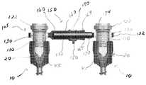
도 1은 트랜스컨넥터의 예시적인 실시예의 사시도이다.1 is a perspective view of an exemplary embodiment of a transconnector.
도 2는 도 1에 도시된 트랜스컨넥터의 측면도이다.FIG. 2 is a side view of the transconnector shown in FIG. 1. FIG.
도 3은 도 1에 도시된 트랜스컨넥터의 단면도이다.3 is a cross-sectional view of the trans connector shown in FIG.
도 4는 도 1의 트랜스컨넥터와 연결에 사용되는 록킹 캡의 측면도이다.4 is a side view of the locking cap used to connect with the transconnector of FIG.
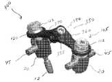
도 5는 트랜스컨넥터의 대안적인 예시적 실시예의 사시도이다.5 is a perspective view of an alternative exemplary embodiment of a transconnector.
도 6은 도 5의 트랜스컨넥터의 부분 사시도이다.FIG. 6 is a partial perspective view of the transconnector of FIG. 5. FIG.
도 7은 도 5에 도시된 트랜스컨넥터의 저면도이다.FIG. 7 is a bottom view of the transconnector shown in FIG. 5. FIG.
도 8은 트랜스컨넥터의 대안적인 예시적 실시예의 사시도이다.8 is a perspective view of an alternative exemplary embodiment of a transconnector.
도 9는 도 8에 도시된 트랜스컨넥터의 측면도이다.FIG. 9 is a side view of the transconnector shown in FIG. 8. FIG.
도 10은 도 8에 도시된 트랜스컨넥터의 부분 단면도이다.FIG. 10 is a partial cross-sectional view of the transconnector shown in FIG. 8.
도 11은 트랜스컨넥터의 대안적인 예시적 실시예의 사시도이다.11 is a perspective view of an alternative exemplary embodiment of a transconnector.
도 12는 도 11에 도시된 트랜스컨넥터의 측면도이다.12 is a side view of the transconnector shown in FIG. 11.
도 13은 도 11에 도시된 트랜스컨넥터의 부분 단면도이다.FIG. 13 is a partial cross-sectional view of the transconnector shown in FIG. 11.
도 14는 도 11의 트랜스컨넥터의 연결에 사용되는 록킹 캡의 측면도이다.FIG. 14 is a side view of the locking cap used to connect the transconnector of FIG. 11. FIG.
도 15는 트랜스컨넥터의 대안적인 예시적 실시예의 사시도이다.15 is a perspective view of an alternative exemplary embodiment of a transconnector.
도 16은 도 15에 도시된 트랜스컨넥터의 다른 사시도이다.FIG. 16 is another perspective view of the transconnector shown in FIG. 15.
도 17a는 트랜스컨넥터의 대안적인 예시적 실시예의 부분 사시도이다.17A is a partial perspective view of an alternative exemplary embodiment of a transconnector.
도 17b는 도 17a의 트랜스컨넥터의 연결에 사용되는 예시적인 뼈 고정 커플링 요소의 사시도이다.FIG. 17B is a perspective view of an exemplary bone fixation coupling element used for connecting the transconnector of FIG. 17A. FIG.
도 17c는 도 17a의 트랜스컨넥터의 연결에 사용되는 세트 스크류의 예시적 실시예의 측면도이다.17C is a side view of an exemplary embodiment of a set screw used for connecting the transconnector of FIG. 17A.
도 17d는 도 17a의 트랜스컨넥터의 연결에 사용되는 하우징의 예시적 실시예의 사시도이다.17D is a perspective view of an exemplary embodiment of a housing used for connecting the transconnector of FIG. 17A.
도 17e는 도 17a의 트랜스컨넥터의 연결에 사용되는 슬라이더의 예시적 실시예의 사시도이다.FIG. 17E is a perspective view of an exemplary embodiment of a slider used to connect the transconnector of FIG. 17A. FIG.
도 17f는 도 17a의 트랜스컨넥터의 연결에 사용되는 뼈 고정 커플링 요소의 예시적 실시예의 단면도로서, 뼈 고정 커플링 요소는 열린 위치에 있다.FIG. 17F is a cross-sectional view of an exemplary embodiment of a bone fixation coupling element used for connection of the transconnector of FIG. 17A, with the bone fixation coupling element in an open position. FIG.
도 17g는 도 17a의 트랜스컨넥터의 연결에 사용되는 뼈고정 커플링 요소의 단면도로서, 뼈 고정 커플링 요소는 닫힌 위치에 있다.FIG. 17G is a cross-sectional view of the bone fixation coupling element used for the connection of the transconnector of FIG. 17A, with the bone fixation coupling element in a closed position. FIG.
도 18a는 트랜스컨넥터의 다른 예시적인 실시예의 부분 사시도이다.18A is a partial perspective view of another exemplary embodiment of a transconnector.
도 18b는 도 18a에 도시된 트랜스컨넥터의 측면도이다.FIG. 18B is a side view of the transconnector shown in FIG. 18A. FIG.
도 19a는 트랜스컨넥터의 다른 예시적 실시예의 부분 사시도이다.19A is a partial perspective view of another exemplary embodiment of a transconnector.
도 19b는 도 19a에 도시된 트랜스컨넥터의 단면도이다.FIG. 19B is a cross-sectional view of the transconnector shown in FIG. 19A.
도 20a는 뼈 고정 커플링 요소의 다른 예시적 실시예의 단면도로서, 뼈 고정 커플링 요소는 열린 위치에 있다.20A is a cross-sectional view of another exemplary embodiment of a bone fixation coupling element, wherein the bone fixation coupling element is in the open position.
도 20b는 도 20a에 도시된 뼈 고정 커플링 요소의 단면도로서, 뼈 고정 커플링 요소는 닫힌 위치에 있다.20B is a cross-sectional view of the bone fixation coupling element shown in FIG. 20A, with the bone fixation coupling element in a closed position.
도 21a는 뼈 고정 커플링 요소의 다른 예시적인 실시예의 다시도이다.21A is a back view of another exemplary embodiment of a bone fixation coupling element.
도 21b는 도 21a에 도시된 뼈 고정 커플링 요소의 측면도이다.FIG. 21B is a side view of the bone fixation coupling element shown in FIG. 21A.
도 22a는 뼈 고정 커플링 요소의 다른 예시적인 실시예의 사시도이다.22A is a perspective view of another exemplary embodiment of a bone fixation coupling element.
도 22b는 도 22a에 도시된 뼈 고정 커플링 요소의 단면도이다.22B is a cross-sectional view of the bone fixation coupling element shown in FIG. 22A.
도 23은 뼈 고정 커플링 요소의 다른 예시적 실시예의 사시도이다.23 is a perspective view of another exemplary embodiment of a bone fixation coupling element.
도 24는 뼈 고정 커플링 요소의 다른 예시적 실시예의 사시도이다.24 is a perspective view of another exemplary embodiment of a bone fixation coupling element.
도 25는 뼈 고정 커플링 요소의 다른 예시적 실시예의 사시도이다.25 is a perspective view of another exemplary embodiment of a bone fixation coupling element.
이하에서, 특정의 예시적인 실시예들은 도면들을 참조하여 설명될 것이며, 유사한 참조부호들은 시종일관 유사한 구성요소들을 지칭하는데 사용된다. 대체적으로, 그러한 실시예들은 횡단-꺾쇠(cross-brace) 즉, 트랜스컨넥터(여기서는 전체적으로 '트랜스컨넥터'라 함)에 관한 것으로서, 비제한적인 예시로서, 트랜스컨넥터는 후방 척추 고정 시술에서 한 쌍의 세로 척추 봉들의 연결에 사용된다. 본 발명은 다른 적용예 및 용도들을 가질 수도 있으며 설명되고 예시된 구조 또는 용도에 제한되어서는 안된다. 이하에서 더 상세히 설명되는 바와 같이, 트랜스컨넥터는 바람직하게 세로 척추 봉에 대향되는 것으로서 뼈 고정 요소를 수납 및/또는 결합한다. 뼈 고정 요소를 직접 수납 및/또는 결합하는 트랜스컨넥터를 제공함으로써, 트랜스컨넥터는 (i) 대체적으로 이식이 더 간단해 질 수 있고, (ii) 종래의 트랜스컨넥터와 비교하여 보다 강하고 단단한 고정 시스템을 제공할 수 있고, (iii) 측면 프로파일(profile)을 최소화할 수 있다.In the following, certain example embodiments will be described with reference to the drawings, wherein like reference numerals are used to refer to like elements throughout. In general, such embodiments relate to cross-braces, ie transconnectors (herein referred to collectively as 'transconnectors'), and by way of non-limiting example, transconnectors are a pair of posterior spinal fixation procedures. Used to connect longitudinal spinal rods. The invention may have other applications and uses and should not be limited to the structures or uses described and illustrated. As will be explained in more detail below, the transconnector preferably receives and / or engages a bone fixation element as opposed to the longitudinal spinal rod. By providing a transconnector that directly stores and / or engages bone fixation elements, the transconnector can (i) be generally implanted more simply, and (ii) provide a stronger and rigid fixation system compared to conventional transconnectors. And (iii) minimize side profile.
사용 시, 바람직하게, 트랜스컨넥터가 변화하는 척추 봉 정렬을 적응하는 것을 허용하도록 트랜스컨넥터는 구성된다. 예를 들어, 바람직하게, 트랜스컨넥터는 뼈 고정 요소들에 대해 각져서 이동하도록 구성될 수 있으므로, 예를 들어, 변화하는 봉 분리 간격들을 가진 수렴 및/또는 분기 세로 척추 봉들, 비-공면(coplanar) 세로 척추 봉들, 및 세로 척추 봉들에 트랜스컨넥터가 적응하게 된다.In use, the transconnector is preferably configured to allow the transconnector to adapt to varying spinal rod alignment. For example, preferably, the transconnector can be configured to move angularly relative to the bone fixation elements, such as, for example, convergent and / or diverging longitudinal spinal rods, coplanar with varying rod separation intervals. ) The transconnector is adapted to the longitudinal spinal rods, and the longitudinal spinal rods.
또한, 트랜스컨넥터는 일반적으로 척추(예들 들어, 요추, 흉추 또는 경추 영역)에 사용되는 것으로서 설명되고 있지만, 당업자라면 예를 들어, 조인트, 긴 뼈 또는 손, 안면, 다리 등의 뼈와 같은 신체의 다른 부분의 고정에도 트랜스컨넥터가 사용될 수 있음을 이해할 것이다. 나아가, 트랜스컨넥터는 예를 들어, 환자의 몸 밖에서 봉들이 접합되는 경우에, 예를 들어, 환자의 척추뼈, 긴 뼈 등과 같은 신체의 외부 고정에 사용될 수도 있다.Transconnectors are also generally described as being used in the spine (e.g., lumbar, thoracic or cervical spine regions), but those skilled in the art will appreciate, for example, that of the body, It will be appreciated that the transconnector can also be used for fastening other parts. Furthermore, the transconnector may be used for external fixation of the body, for example in the case of rods being joined outside the patient's body, for example in the patient's vertebrae, long bones and the like.
트랜스컨넥터는 스테인리스 스틸, 티타늄, 티타늄 합금, 폴리머, 형상 기억 합금 등을 포함하지만 그에 한정되지 않는 그 어떤 생체적합성 물질들로 구성될 수 있다.The transconnector may be comprised of any biocompatible materials, including but not limited to stainless steel, titanium, titanium alloys, polymers, shape memory alloys, and the like.
세로 척추 봉은 강성 봉, 비-강성 봉, 유연성 또는 다이나믹 봉 등을 포함할 수 있지만 이에 제한되지는 않는 점을 이해할 것이다. 대안적으로, 세로 척추 봉은 전혀 봉이 아닐 수 있으며 예를 들어, 플레이트 모양일 수도 있다. 트랜스컨넥터는 그 용도에 있어서 세로 척추 봉의 그 어떤 형태로 제한되는 것은 아님을 이해해야 한다.It will be appreciated that longitudinal spinal rods may include, but are not limited to, rigid rods, non-rigid rods, flexible or dynamic rods, and the like. Alternatively, the longitudinal spinal rod may not be a rod at all or may be plate-shaped, for example. It is to be understood that the transconnector is not limited to any form of longitudinal spinal rod in its use.
아래에서 더 상세히 설명되는 바와 같이, 트랜스컨넥터는 뼈 고정 요소들과 함께 사용될 수 있다. 당업자에 의해 대체적으로 이해되는 바와 같이, 뼈 고정 요소는 다축 또는 단축 척추경 나사, 척추경 후크를 포함하는 후크들(단축 및 다축 모두), 교차 돌기 후크(transverse process hook), 고리판밑 후크(sublaminar hook), 또는 다른 파스너, 클램프 또는 임플란트를 포함할 수 있지만 이에 제한되는 것은 아님을 이해해야 한다. 도면들에 대체적으로 도시된 바와 같이, 뼈 고정 요소(10)은 확대된 헤드부(미도시)를 가진 뼈 앵커(뼈 스크류로 도시됨)(12), 한 쌍의 이격된 아암들(28)(30)에 의해 구획되는 봉-수납 채널(25)(상부 로딩 U-자형 봉-수납 채널로 도시됨)을 포함할 수 있다. 일반적으로 알려진 바와 같이, 뼈 고정 요소들(10)은 삽입 조립체(32)(예를 들어, 도 20a 및 도 20b에 도시된 바와 같이)를 포함할 수 있으며, 삽입 조립체(32)는 본체부(20) 내부에 슬라이딩되게 배치될 수 있다. 삽입 조립체(32)는 하나의 조각으로 된 삽입 부재일 수 있다. 대안적으로, 삽입 조립체(32)는 2개 또는 그 이상의 조각들의 형태일 수 있다. 또한, 뼈 고정 요소들(10)은 도 16에 가장 잘 도시된 바와 같이, 밀폐 캡(40)을 일반적으로 포함할 수 있다. 사용 시, 뼈 앵커(12)의 확대된 단부는 본체부(20)의 하단으로부터 분리되어 그 내부에 배치될 수 있으므로 뼈 앵커(12)는 본체부(20)에 대해 다축 회전을 할 수 있다. 대안적으로, 뼈 앵커(12)는 때때로 일축(mono-axial) 뼈 고정 요소로서 불려지는 하나로 된 구조를 형성하기 위해 본체부(20)와 일체로 형성될 수 있다.As described in more detail below, the transconnector can be used with bone fixation elements. As generally understood by one of ordinary skill in the art, the bone fixation element may be a multiaxial or uniaxial pedicle screw, hooks (both short and multiaxial) including pedicle hooks, transverse process hooks, sublaminar hooks hooks, or other fasteners, clamps or implants, but are not limited thereto. As generally shown in the figures, the
척추 봉(spinal rod)(45)이 봉-수납 채널(25)에 삽입된 후, 외과의사는 예를 들어, 밀폐 캡(40)을 회전시킴에 의해 본체부(20)에 대한 척추 봉(45)의 위치 및 본체부(20)에 대한 뼈 앵커(12)의 위치를 고정할 수 있다. 밀폐 캡(40)을 회전시키면, 밀폐 캡(40)은 봉-수납 채널(25)에 수납된 척추 봉(45)에 하방 힘을 가하고, 이어서, 척추 봉(45)은 삽입 조립체(32)에 하방 힘을 가하고, 삽입 조립체(32)는 뼈 앵커(12)의 확대된 헤드부 주위를 가압하여, 본체부(20)에 대해 뼈 앵커(12)의 위치를 고정하게 된다. 또한, 밀폐 캡(40)을 회전시키면, 밀폐 캡(45)과 삽입 조립체(32) 사이에 척추 봉(45)을 끼움으로써 본체부(20)에 대한 척추 봉(45)의 위치를 고정할 수 있다. 그러나, 트랜스컨넥터의 사용은, 뼈 고정 요소(10) 및 예를 들어 사이드 로딩(side loading)과 같은 다른 스타일의 그 어떤 특정한 형태에 제한되는 것은 아니며, 예를 들어, 삽입 조립체를 사용하지 않거나, 삽입 부재를 사용하지 않거나, 밀폐 캡을 사용하지 않는 등과 같이 다른 형태들로 사용될 수 있음을 이해해야 한다.After a
도 1 내지 도 4에 도시된 바와 같이, 트랜스컨넥터(100)은 뼈 고정 커플링 요소(105) 및 브리지 부재(150)를 포함할 수 있다. 뼈 고정 커플링 요소(105)는 록킹 캡(110), 부싱(130) 및 너트(122)를 포함할 수 있다. 부싱(130)은 대체로 록킹 캡(110) 및 브리지 부재(150)를 연결하도록 구성되는 한편 트랜스컨넥터(100)가 위치에 록킹될 때까지 록킹 캡(110)에 대한 브리지 부재(150)의 이동을 용이하게 한다. 도 3에 가장 잘 도시된 바와 같이, 부싱(130)은 외부 표면(132)과 중앙 통로(134)를 포함할 수 있고, 중앙 통로(134), 바람직하게 아래에서 더 상세히 설명되는 바와 같이, 록킹 캡(110)의 테이퍼진 중앙부(118)는 록킹 캡(110)을 그 안에 수납하도록 구성되어 있다. 부싱(130)의 외부 표면(132)은 아치형 표면을 포함할 수 있으므로, 사용 시, 부싱(130)은 록킹 캡(110)에 대한 브리지 부재(150)의 이동, 바람직하게 다축 이동 따라서, 그에 부착된 뼈 고정 요소(10)에 대한 브리지 부재(150)의 이동, 바람직하게 다축 이동을 가능 및/또는 용이하게 한다. 부싱(130)을 통한 다축 연결을 제공함으로써, 록킹 캡(110)을 결합시키기 위해 브리지 부재(150)를 구부릴 필요가 실질적으로 또는 완전히 제거된다. 따라서, 이것은 결과적으로 조립 실패를 야기하게 되는, 브리지 부재(150)의 부정확한 구부림의 결과로서 뼈 고정 요소에 발생할 수도 있는 그 어떤 사전-로딩(pre-loading)을 실질적으로 제거한다. 또한, 다축 연결의 제공은 정확한 브리지 부재(150)의 사전-선택(pre-selecting)의 위험성을 감소시킴으로써 총 수술 시간과 시행 착오를 실질적으로 경감한다. 또한, 부싱(130)은 그 안에 형성된 슬롯(136)(도 1에 가장 잘 도시됨)을 포함할 수 있다. 당업자에 의해 평가되는 바와 같이, 슬롯(136)은 그것이 록킹 캡(110)의 테이퍼진 중앙부(118) 위로 움직일 때 부싱(130)의 팽창을 허용한다.As shown in FIGS. 1-4, the
도 4에 가장 잘 도시된 바와 같이, 록킹 캡(110)은 근위단(112), 원위단(114), 및 그 사이에 위치된 중앙부(116)를 포함할 수 있다. 중앙부(116)는 부싱(130)을 수납하도록 구성된다. 중앙부(116)는 테이퍼진 표면(118)을 포함할 수 있다. 바람직하게, 원위단(114)은 뼈 고정 요소(10)에 형성된 내부 나사산과의 결합을 위한 다수의 외부 나사산(116)을 포함한다. 대안적으로, 원위단(114)은 뼈 고정 요소(10)에 형성된 외부 나사산과의 결합을 위한 내부 나사산 또는 스냅-고정, 부분 캠 고정 등을 포함하지만 그에 한정되지 않는 그 어떤 다른 연결 수단을 포함할 수 있다. 이런 식으로, 바람직하게 록킹 캡(110)은 뼈 고정 요소(10)의 본체부(20)와 직접 결합한다. 본질적으로, 본 실시예에 있어서, 바람직하게, 록킹 캡(110)은 뼈 고정 요소들(10)과 함께 대체로 사용되는 밀폐 캡(40)을 대체 및/또 는 그것으로서 작용한다. 또한, 록킹 캡(110)은 수술 도구와 결합을 위한 드라이드 리세스(drive recess)(119)를 바람직하게 포함한다.As best shown in FIG. 4, the locking
도시된 바와 같이, 또한, 록킹 캡(110)의 근위단(112)은 내부 나사가 형성된 너트(122)와의 결합을 위한 다수의 외부 나사산(120)을 포함할 수 있다. 대안적으로, 근위단(112)은 외부 나사산이 형성된 너트 또는 캡과의 결합을 위한 다수의 내부 나사산을 포함할 수 있다. 나사가 형성된 너트(122)를 회전시키면, 부싱(130)을 통해 록킹 캡(110)에 대한 브리지 부재(150)의 다축 연결을 이루어 고정된다. 즉, 나사가 형성된 너트(122)를 회전시키면, 너트(122)는 부싱(130)의 상면에 접촉되고, 결과적으로 부싱(130)은 록킹 캡(110)에 대해 하방으로 움직인다. 록킹 캡(110)의 테이퍼진 중앙부(118)를 따른 부싱(130)의 하방 이동은 부싱(130)을 팽창되게 하고, 이어서 록킹 캡(110)과 브리지 부재(150) 사이에 부싱(130)을 박히게 하여, 결과적으로 브리지 부재(150)의 위치를 록킹 캡(110), 따라서 뼈 고정 요소(10)와 그에 고정된 세로 척추 봉(45)에 대해 고정시킨다.As shown, the proximal end 112 of the
사용 시, 바람직하게 록킹 캡(110)과 부싱(130)은 브리지 부재(150)가 뼈 고정 요소(10)의 본체부(20)에 접촉되지 않도록 구성된다. 예를 들어, 록킹 캡(110)의 테이퍼진 중앙부(118)와 부싱(130)의 중앙 통로(134)는 브리지 부재(150)가 뼈 고정 요소(10)의 본체부(20)에 접촉되지 않도록 구성된다. 대안적으로, 록킹 캡(110)은 돌기 또는 멈춤 부재 바람직하게 브리지 부재(150)가 뼈 고정 요소(10)의 본체부(20)에 접촉되는 것을 방지하는 원주 돌출부(circumferential ledge)를 구비할 수 있다(이하에서 더욱 상세히 설명됨).In use, the locking
수술 시, 외과의사는 록킹 캡(110)에 형성된 드라이브 리세스(119)에 동시에 결합하도록 구성된 수술 도구(예, 드라이브 툴)에 너트(122)를 결합하고, 수술 도구를 회전시키게 되면, 록킹 캡(110)이 뼈 고정 요소(10)에 대해 정지된 채 유지되도록 너트(122)를 결합하는 한편 록킹 캡(110)에 대해 너트(122)가 회전하도록 너트(122)를 결합한다. 이러한 방식으로, 나사산이 형성된 너트(122)를 회전시키면 너트(122)를 부싱(130)의 상부 표면에 접촉시켜, 록킹 캡(110) 따라서 전술한 바와 같이 뼈 고정 요소(10) 및 그에 부착된 세로 척추 봉(45)에 대한 브리지 부재(150)의 위치를 고정한다. 뼈 고정 요소(10)에 대해 록킹 캡(110)이 더 이상 회전되는 것을 방지함으로써, 뼈 고정 요소(10)의 파괴를 유발시켜 뼈 고정 요소(10)를 포함하는 전체 구성을 교체하게 될 수도 있는 과도한 조임의 가능성이 실질적으로 방지된다. 또한, 뼈 고정 요소(10)에 대한 록킹 캡(110)의 추가적인 회전을 방지하고 브리지 부재(150)가 뼈 고정 요소(10)의 본체부(20)에 접촉되는 것을 방지함으로써, 뼈 고정 요소(10)의 로딩(loading)이 실질적으로 감소 및/또는 경감되어, 구조물의 파괴의 가능성이 더욱 감소된다.During surgery, the surgeon couples the
바람직하게, 브리지 부재(150)는 록킹 캡(110)과 부싱(130)을 수납하기 위해 그 어느 일단에 형성된 적어도 하나의 구멍(152)을 포함한다. 또한, 브리지 부재(130)는 제1 부재(160)와 제2 부재(170)를 포함할 수 있고, 제1 부재(160)와 제2 부재(170)는 서로에 대해 움직일 수 있으므로 트랜스컨넥터(100)의 길이는 뼈 고정 커플링 요소들(105) 사이, 따라서 세로 척추 봉들(45) 사이의 간격에 상응하게 조절될 수 있다. 브리지 부재(150)의 길이를 조절 가능하게 함으로써, 트랜스컨넥 터(100)는 변화된 중간 내지 측면 조절을 허용할 수 있다. 대안적으로, 브리지 부재(150)는 단일의, 조절불가능한 고정된 길이를 가진 부재 형태일 수 있다. 여러가지의 고정 길이 브리지 부재들(150)은 키트 형태로 제공될 수 있다.Preferably, the
도 1 내지 도 3에 도시된 바와 같이, 제1 부재(160)는 외부 끼움 봉(telescopic rod)(162)의 형태일 수 있는 반면 제2 부재(170)는 내부 끼움 봉(172) 형태일 수 있으며, 내부 끼움 봉(172)은 외부 끼움 봉(162) 내부에 신축 가능하게 수납된다. 외부 끼움 봉(162)은 그 안에 형성된 내부 보어(164)를 가진 속이 빈 실린더로서 형성될 수 있다. 보어(164)는 내부 끼움 봉(172)을 슬라이딩 가능하게 수납하도록 구성됨으로써 내부 끼움 봉(172)은 트랜스컨넥터(100)의 세로 축에 대해 회전할 수 있고 그것을 따라 이동할 수 있다. 또한, 제1 및 제2 부재들(160)(170)은 브리지 부재의 길이가 조절되도록 서로에 대해 미끄러지는 측면 부재들 형태일 수 있다. 제1 및 제2 부재들의 다른 배열들 역시 조절 가능한 브리지 부재를 구성하기 위해 고려될 수 있다.As shown in FIGS. 1-3, the
또한, 브리지 부재(150)는 서로에 대하여 제1 및 제2 부재들(160)(170)(예, 내측 및 외부 끼움 부재(162)(172))의 위치를 고정하기 위한 메커니즘을 포함할 수 있다. 상기 메커니즘은 예를 들어, 스크류, 볼트, 라체트 등을 포함하지만 이에 한정되지 않는 그 어떤 메커니즘일 수 있다. 도시된 바와 같이, 바람직하게, 브리지 부재(150)는 외부 끼움 봉(162) 주변에 배치된 링(18)을 포함할 수 있고, 링(180)은 제1 위치로부터 제2 위치까지 외부 끼움 봉(162) 주변에 미끄러지게 배치되며, 여기서, 제1 위치(도 3에 가장 잘 도시됨)에서 내부 끼움 봉(172)은 외부 끼움 봉(162)에 대해 자유롭게 움직일 수 있지만 링(180)이 제2 위치(도 2에 가장 잘 도시됨)로 움직일 때 내부 끼움 봉(172)은 외부 끼움 봉(172)에 대해 고정된다. 바람직하게, 외부 끼움 봉(162)은 링(180)이 제2 위치로 움직일 때 링(180)에 의해 압착-록킹 즉, 압축되도록 구성된다. 도시된 바와 같이, 외부 끼움 봉(162)은 그 일단으로부터 확장하는 복수의 슬롯(166)을 가지도록 구성될 수 있으며, 바람직하게, 슬롯(166)에 인접한 봉(162)의 적어도 일 부분은 두껍게 된 영역 및/또는 하나 또는 그 이상의 돌기들(167)과 통합되므로 슬롯(166)은 링(180)이 제2 위치로 움직일 때 외부 끼움 봉(162)의 압착 록킹을 용이하게 한다. 즉, 제1 위치로부터 제2 위치까지 링(180)이 움직이면, 외부 끼움 봉(162)에 형성된 슬롯(166)을 압축시켜 외부 끼움 봉(162)에 형성된 두껍게 된 영역 및/또는 돌기들(167)을 내부 끼움 봉(172)의 상대 위치에 접촉 및 고정시키게 된다.In addition, the
트랜스컨넥터(200)의 대안적 실시예가 도 5 내지 도 7에 도시된다. 이 실시예에 있어서, 브리지 부재(250)의 제1 및 제2 부재들(260)(270)은 플레이트 부재들(262)(272)의 형태일 수 있으며, 여기서 제2 플레이트 부재(272)는 제1 플레이트 부재(262)에 대해 미끄러지고 바람직하게 그 내부에 수납 가능하므로, 제2 플레이트 부재(272)는 트랜스컨넥터(200)의 상대 길이를 조절하기 위해 트랜스컨넥터(200)의 세로 축을 따라 제1 플레이트 부재(262)에 대해 이동할 수 있다. 도 7에 가장 잘 도시된 바와 같이, 제1 플레이트 부재(262)는 제2 플레이트 부재(272)를 미끄러지게 수납하기 위한 텅(tongue)(264)을 포함할 수 있다.An alternative embodiment of
브리지 부재(250)는 제1 플레이트 부재(262)에 대한 제2 플레이트 부재(272) 의 위치를 고정하기 위한 나사산이 형성된 파스너(280) 및 너트(282)를 포함할 수 있다. 그러나, 전술한 바와 같이, 제1 및 제2 플레이트 부재들(262)(272)의 위치를 서로에 대해 고정하기 위한 다른 수단들의 통합을 생각해 볼 수 있다. 보다 바람직하게, 제1 플레이트 부재(262)는 가늘고 긴 슬롯(266)을 포함하는 한편 제2 플레이트 부재(272)는 그 안에 형성된 구멍(276)을 포함한다. 구멍(276)은 나사산이 형성된 파스너(280)를 수납하도록 구성된다. 바람직하게, 구멍(276)과 파스너(280)는 너트(282)가 회전될 때 파스너(280)가 회전되는 것을 방지하기 위해, 각각 리세스(278) 및 돌출부(284)를 가지도록 구성된다(도 7에 가장 잘 도시됨). 사용 시, 너트(282)를 회전시켜 제1 및 제2 플레이트 부재들(262)(272)의 상대 위치를 고정한다.The
도 5 내지 도 7에 도시된 뼈 고정 커플링 요소는 도 1 내지 도 4와 관련하여 도시되고 설명된 뼈 고정 커플링 요소(105)와 동일하므로, 뼈 고정 커플링 요소에 대한 설명은 생략한다.Since the bone fixation coupling element shown in FIGS. 5-7 is the same as the bone
트랜스컨넥터(300)의 대안적인 실시예가 도 8 내지 도 10에 도시된다. 이 실시예에 있어서, 브리지 부재(350)는 제1 및 제2 부재들(360)(370)의 형태일 수 있으며, 여기서 제1 부재(360)는 제2 부재(370)에 회동 가능하게 연결 또는 힌지 결합된다. 도시된 바와 같이, 바람직하게, 제1 부재(360)는 트랜스컨넥터(300)의 세로 축을 실질적으로 교차할 수 있는 회동 축(380)을 통해 제2 부재(370)에 회동 가능하게 연결 또는 힌지 결합된다. 즉, 제1 및 제2 부재들(360)(370)의 회동 조절은 브리지 부재(350)가 해부학적 축평면에서 굴곡되게 할 수 있다. 이러한 방식에서, 제2 부재(370)에 대한 제1 부재(360)의 회동 조절은 트랜스컨넥터(300)의 길이를 변경할 것이다. 제2 부재(370)에 대한 제1 부재(360)의 회동 조절은 브리지 부재(350)가 배면으로 움직이게 하여 트랜스컨넥터의 총 길이를 감소시킬 수 있다.Alternative embodiments of the
도시된 바와 같이, 바람직하게 제2 부재(370)는 그 안에 형성된 구멍들(373)를 포함하고, 구멍(372)은 제1 부재(360)로부터 확장하는 돌기(361)을 수납하도록 구성되고, 바람직하게 돌기(361)는 복수의 탭(362)를 포함한다. 브리지 부재(350)는 나사산이 형성된 파스너 또는 세트 스크류(385)를 더 포함할 수 있다. 바람직하게, 파스너(385)는 제1 부재(360)에 결합될 수 있으므로 파스너(385)를 회전시키면 돌기(362), 더 바람직하게 복수의 탭(362)를 팽창시키게 되고 제1 부재(360)의 위치를 제2 부재(370)에 대해 고정시킨다.As shown, the second member 370 preferably comprises holes 373 formed therein, the
도 8 내지 도 10에 도시된 뼈 고정 커플링 요소는 도 1 내지 도 4와 관련하여 도시되고 전술된 뼈 고정 커플링 요소(105)와 동일하므로, 뼈 고정 커플링 요소의 설명은 생략한다.The bone fixation coupling element shown in FIGS. 8-10 is the same as the bone
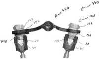
트랜스컨넥터(400)의 대안적인 실시예가 도 11 내지 도 14에 도시된다. 이 실시예에 있어서, 트랜스컨넥터의 부가적인 중간-측면 조절을 제공하기 위해 브리지 부재(450)의 하나 또는 양쪽 끝단(일 끝단만 도시됨)이 록킹 캡(410)를 수납하기 위한 가늘고 긴 슬롯(452)을 포함할 수 있는 것을 제외하고는 브리지 부재(450)는 도 8 내지 도 10과 관련하여 전술한 브리지 부재(350)와 실질적으로 동일하다. 당업자에 의해 평가되는 바와 같이, 가늘고 긴 슬롯(452)을 제공함으로써, 트랜스컨넥터(400)는 록킹 캡(110)(410)과 결합하는 부가적인 유연성이 제공될 수 있다. 도시된 바와 같이, 바람직하게, 가늘고 긴 슬롯(452)이 통합되는 경우, 부싱(130)이 배제될 수 있다. 그러나, 부싱(130)은 가늘고 긴 슬롯(452)과 함께 사용될 수 있음을 이해해야 한다. 또한, 바람직하게, 부싱(130)이 배제되는 경우, 전술한 이유들에 의해 브리지 부재(450)가 뼈 고정 요소(10)와 접촉하는 것을 방지하기 위해 록킹 캡(410)은 주변 돌기 또는 멈춤 부재(415)를 포함한다.An alternative embodiment of
트랜스컨넥터(400)는 가늘고 긴 슬롯(452)을 포함하는 것처럼 설명되고 도시되었지만, 본 명세서에서 설명된 그 어떤 트랜스컨넥터들도 가늘고 긴 슬롯을 포함하도록 개량될 수 있음을 유의해야 한다.Although the
도 11 내지 도 14에 도시된 부싱 및 너트를 포함하는 뼈 고정 커플링 요소의 다른 구성요소들은 도 1 내지 도 4와 관련하여 전술된 부싱(130) 및 너트(122)와 동일하므로, 이들 구성요소들의 설명은 생략한다.The other components of the bone fixation coupling element comprising the bushings and the nuts shown in FIGS. 11-14 are the same as the
사용 시, 브리지 부재는 미리-조립된 형태로 제공될 수 있다. 또한, 브리지 부재는 그곳에 부싱이 부착된 미리-조립된 형태로 제공될 수 있다. 그러나, 브리지 부재는 미리-조립된 형태로 제공될 수 있지만, 브리지 부재의 제1 및 제2 부재들은 서로에 대해 이동가능하게 및/또는 회전가능하게 조절될 수 있다. 즉, 예를 들어, 브리지 부재의 제1 및 제2 부재들은 서로에 대해 여전히 자유롭게 이동가능하다(예, 이동, 회전 등).In use, the bridge member may be provided in a pre-assembled form. In addition, the bridge member may be provided in a pre-assembled form with a bushing attached thereto. However, although the bridge member may be provided in a pre-assembled form, the first and second members of the bridge member may be adjusted to be movable and / or rotatable relative to each other. That is, for example, the first and second members of the bridge member are still freely movable (eg, moving, rotating, etc.) with respect to each other.
뼈 고정 요소들(10)이 환자의 척추뼈를 따라 그들의 필요한 방위 및 위치에서 환자의 척추뼈의 중간선의 어느 한 측면에 이식된 후 그리고 세로 척추 봉들(45)이 뼈 고정 요소(10)의 봉-수납 채널(25) 내부에 안착된 후, 세로 척추 봉 들(45)을 뼈 고정 요소들(10)의 봉-수납 채널(25)에 고정하기 위해 록킹 캡이 표준 밀폐 캡(40) 대신에 사용될 수도 있다. 다음, 브리지 부재들은 브리지 부재를 록킹 캡에 위치 및/또는 고정시켜, 한 쌍의 세로 척추 봉들(45) 사이에 시술될 수 있다. 바람직하게, 전술한 바와 같이, 부싱 및/또는 록킹 캡은 브리지 부재가 뼈 고정 요소(10)의 본체부(20)에 직접 접촉하는 것을 방지하도록 구성될 수 있다. 브리지 부재의 위치, 방위, 및/또는 길이는 그 필요한 위치가 달성될 때까지 그 후에 조절될 수 있다. 일단 달성되면, 너트(122)는 뼈 고정 요소(10)에 대한 브리지 부재의 위치를 고정되게 유지하기 위해 단단히 조여질 수 있다. 또한, 링(180)의 이동, 너트(282)의 회전, 스크류(385)의 회전 등은 서로에 대한 브리지 부재의 제1 및 제2 부재들의 상대 위치를 고정하기 위해 수행될 수 있다. 대안적으로, 링(180)의 이동, 너트(282)의 회전, 스크류(285)의 회전 등은 너트(122)의 회전에 앞서 수행될 수 있다.After the
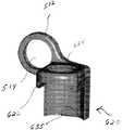
도 15 및 도 16을 참조하여, 트랜스컨넥터(500)의 또 다른 예시적인 실시예가 설명된다. 트랜스컨넥터(500)는 한 쌍의 뼈 고정 커플링 요소들(510) 및 브리지 부재(550)를 포함할 수 있다.With reference to FIGS. 15 and 16, another exemplary embodiment of a
인용에 의해 그 전체 내용이 본 명세서에 합체되고 '척추 봉들의 커플링을 위한 연결 트랜스컨넥터'로 명명된 미국 특허 출원 번호 10/684,351에 개시된 바와 같이, 브리지 부재(550)는 측면 봉(560)의 어느 일단에 위치 및/또는 그에 부착된 록킹 요소(580)를 가진 측면 봉(560)의 형태일 수 있다. 도시된 바와 같이, 측면 봉(560)은 원통형 단면 영역과 인접한 뼈 고정 커플링 요소들(510) 사이로 확장하 기에 충분한 길이를 가질 수 있다. 당업자에 의해 인정되는 바와 같이, 그러나, 측면 봉(560)은 직사각형, 정사각형, 플레이트 형상 등을 포함하지만 이에 한정되지 않는 그 어떤 적절한 형상을 취할 수 있다.As disclosed in US patent application Ser. No. 10 / 684,351, the entire contents of which are incorporated herein by reference and designated as 'connecting transconnectors for coupling of spinal rods', the
측면 봉(560)의 필요한 위치가 얻어지면, 뼈 고정 커플링 요소(510)에 대한, 따라서 그 안에 안착된 뼈 고정 요소(10) 및 세로 척추 봉(45)에 대한 측면 봉(560)의 고정을 유지하기 위해 록킹 요소(580)가 제공될 수 있다. 즉, 록킹 요소(580)는 제1 위치로부터 제2 위치까지 움직이도록 구성될 수 있다. 제1 위치에서, 록킹 요소(580)는 측면 봉(560)에 대한 뼈 고정 커플링 요소들(510)의 회전 및/또는 이동을 조절할 수 있다. 제2 위치에서, 록킹 요소(580)는, 회전 및 이동되게, 연결된 뼈 고정 커플링 요소들(510)에 대한 측면 봉(560)의 위치를 고정할 수 있으므로, 세로 척추 봉들(45)에 대한 측면 봉(560)의 상대 위치를 고정할 수 있다. 록킹 요소(580)에 힘을 가하면, 록킹 요소(580)는 제2 위치에 구성될 수 있다.Once the required position of the side rods 560 is obtained, the fixation of the side rods 560 relative to the bone anchoring
록킹 요소(580)는 록킹 슬리브(585)와 칼라(collar)(590)을 포함할 수 있다. 대안적으로, 그러나, 록킹 요소(580)는 예를 들어, 뼈 고정 커플링 요소들(510)과 측면 봉(560)에 직접 상호 연결될 수 있는 단일의 부품 형태일 수 있는 다른 실시예들을 취할 수 있다.The locking
록킹 슬리브(585)는 측면 봉(560)의 길이를 따라 슬라이딩 가능하게 위치될 수 있으므로 트랜스컨넥터(500)가 세로 척추 봉들(45) 사이의 변화하는 중간 측면 간격들을 수용할 수 있다. 도시된 바와 같이, 록킹 슬리브(585)는 그곳을 확장하여 관통하는 관통 보어를 가진 대체로 원통형 부재 형태일 수 있다. 바람직하게, 관통 보어는 측면 봉(560)을 수납하기 위한 형상인 반면 록킹 슬리브(585)의 외부 표면은, 아래에서 더 상세히 설명되는 바와 같이, 칼라(590)의 관통 보어를 수납하는 형상이다. 보다 바람직하게, 록킹 슬리브(580)의 관통 보어는 측면 봉(560)을 미끄러지게 수납할 수 있는 크기를 가지므로 트랜스컨넥터(500)는 측면 봉(560)의 길이를 따라 록킹 요소들(580)의 슬라이딩에 의해 세로 척추 봉들(45) 사이의 변화하는 간격들을 수용 가능하게 한다.The locking
바람직하게, 일 끝단에 인접한 록킹 슬리브(585)의 외부 표면의 외경이 다른 끝단에 인접한 록킹 슬리브(585)의 외부 표면의 직경보다 더 크도록, 록킹 슬리브(585)는 그 일 끝단으로부터 확장하는 테이퍼진 외부 표면을 가진다. 또한, 바람직하게 록킹 슬리브(585)는 일단으로부터 타단까지 확장하는 관통 벽 슬릿(through wall slit)을 포함한다. 바람직하게, 슬릿은 록킹 슬리브(585)가 확장하여 측면 봉(560)에서 록킹 슬리브(585)의 설치를 용이하게 한다. 아래에서 더 상세히 설명되는 바와 같이, 록킹 요소(580)에 대한 측면 봉(560)의 위치를 고정하기 위한 힘이 록킹 슬리브(585)에 가해질 때와 같이, 또한 바람직하게 슬릿은 록킹 슬리브(585)가 측면 봉(560) 주위에 접촉하는 것을 허용한다.Preferably, the locking
전술한 바와 같이, 또한 록킹 요소(580)는 칼라(590)을 포함할 수 있고, 칼라(590)는 록킹 슬리브(585)와 뼈 고정 커플링 요소(510) 사이의 포지셔닝을 위한 그 어떤 적절한 모양을 가질 수 있다. 측면 봉(560)이 뼈 고정 커플링 요소들(510)에 대해 보편적으로 조절될 수 있고, 측면 봉(560)이 세로 척추 봉들(45)에 대해 보편적으로 조절될 수 있도록, 칼라(590)는 록킹 슬리브(585)와 뼈 고정 커플링 요 소(510) 사이에 위치되도록 구성될 수 있다. 즉, 바람직하게, 뼈 고정 커플링 요소(510)에 대한 측면 봉(560)의 보편적인 조절을 용이하게 하도록, 칼라(590)는 뼈 고정 커플링 요소(510)에 형성된 내부 오목 표면과 결합하기 위한 볼록 외부 표면을 포함한다. 이러한 보편적인 조절은 트랜스컨넥터(500)가 예를 들어, 척추 봉들 및 비-공면 척추 봉들(45)의 수렴 또는 분기를 포함하는 변화하는 척추 봉 정렬들을 수용하는 것을 허용한다.As noted above, the locking
또한, 칼라(590)는 그곳을 통해 관통하여 확장하는 관통 보어를 가질 수 있고, 관통 보어는 록킹 슬리브(585) 및 측면 봉(560)을 그 안에 수납하기 위한 모양을 갖는다. 바람직하게, 칼라(590)는 록킹 슬리브(585)의 전체 길이보다 더 작은 전체 길이를 가지므로, 칼라(590)는 록킹 슬리브(585)의 끝단들 사이에 미끄러지게 위치되도록 구성되고 칼라(590)는 록킹 슬리브(585)의 길이를 따라 조절되게 위치될 수 있다. 또한, 칼라(590)는 제1 끝단으로부터 제2 끝단까지 확장하는 관통 벽 슬릿을 포함할 수 있고, 슬릿은 록킹 슬리브(585)에 대한 칼라(590)의 보다 쉬운 설치를 허용한다. 즉, 록킹 슬리브(585)에 형성된 슬릿과 유사하게, 칼라(590)에 형성된 슬릿은 보다 용이한 설치를 허용하기 위해 칼라가 확장되는 것을 허용한다.The
조립하는 동안, 트랜스컨넥터의 개별 부품들의 설치 용이성에 부가하여, 록킹 슬리브(585)와 칼라(590)에 형성된 슬릿들은 두 개의 부품들이 축방향 및 회전 방향으로 서로 록킹되는 것을 허용한다. 즉, 바람직하게 록킹 슬리브(585)의 외부 표면은 칼라(590)의 비확장 관통 보어의 직경보다 더 작도록 구성된 제1 끝단 부근의 직경을 가지는 한편, 록킹 슬리브(585)의 외부 표면은 칼라(590)의 비확장 관통 보어의 직경 보다 더 크게 구성된 제2 끝단 부근의 직경을 가진다. 따라서, 칼라(590)가 록킹 슬리브(585)의 제1 끝단 부근에 위치될 때, 록킹 슬리브(585)와 칼라(590)는 서로에 대해 자유롭게 움직일 수 있다. 그러나, 칼라(590)가 록킹 슬리브(585)의 제2 끝단 부근에 위치될 때, 록킹 슬리브(585)의 더 큰 직경은 칼라(590)의 내부 표면과 간섭되어, 록킹 슬리브(585)와 칼라(590) 사이의 마찰 록킹을 야기한다. 이 힘은 측면 봉(560)의 외부 표면에 대하여 록킹 슬리브(585)가 압착을 일으키는 한편 동시에 뼈 고정 커플링 요소(510)와 결합하도록 칼라(590)를 확장시킴으로써, 서로에 대하여 측면 봉(560)과 록킹 요소(580)의 상대 위치를 회전 및 이동되게 록킹하게 된다. 즉, 바람직하게, 이 록킹 작용은 록킹 슬리브(585)의 약간의 압착과 칼라(50)의 약간의 팽창을 야기하여, 바람직하게 측면 봉(560)에 대한 록킹 슬리브(585)의 마찰 록킹 및 뼈 고정 커플링 요소(510)에 대한 칼라(590)의 마찰 록킹을 용이하게 한다.During assembly, in addition to the ease of installation of the individual parts of the transconnector, the slits formed in the locking
전술한 바와 같이, 또한 트랜스컨넥터(500)는 한 쌍의 뼈 고정 커플링 요소들(510)을 포함할 수 있다. 바람직하게, 뼈 고정 커플링 요소들(510)은 뼈 고정 요소들, 바람직하게 뼈 고정 요소들(10)의 본체부(20)와 서로 결합하는 한편 록킹 요소들(580)을 통해 브리지 부재(550)와 결합하도록 구성된다.As mentioned above, the
도시된 바와 같이, 브리지 부재(550)는 브리지 부재(550)(예, 측면 봉(560))와 록킹 요소(580)를 수납하도록 구성된 개구(514)를 가진 측면 봉 결합부(512)를 포함할 수 있다. 개구(514)는 록킹 요소(580), 바람직하게 칼라(590)의 외측 볼록 표면을 조절되게 수납하기 위한 내측 오목 표면을 가질 수 있으므로, 구형 조절 조 립체를 제공한다. 대안적으로, 개구(514)는 칼라(590)의 외측 오목 표면을 조절되게 수납하기 위한 내측 볼록 표면을 가질 수 있다. 이러한 구형 조절 구성은 측면 봉(560)이 각각의 뼈 고정 커플링 요소(510)에 대해, 따라서 세로 척추 봉들(45)에 대해 보편적으로 조절되게 함으로써, 다양한 종류의 척추 봉 장치들을 트랜스컨넥터(500)가 용이하게 수용하도록 허용한다.As shown,
본 명세서에서 측면 봉 결합부(512)는 고리 또는 원형 모양을 가진 것으로서 설명 및 도시되었지만, 측면 봉 결합부(512)는 계란형, 타원형, 정사각형, 직사각형 등을 포함하지만 이에 한정되지는 않는 브리지 부재(550)(예, 측면 봉(560)) 및 록킹 요소(580)를 수용하기 위한 그 어떤 적절한 형태를 취할 수 있다. 바람직하게, 측면 봉 결합부(512), 측면 봉(560), 및 록킹 요소(580)의 결합 표면들 모두는 실질적으로 유사한 모양을 가진다. 뼈 고정 커플링 요소(510)는 예를 들어, 스크류와 같은 기구적 연결을 포함하지만 그에 한정되지는 않는 그 어떤 공지의 수단에 의해 브리지 부재(550)에 연결될 수 있다.Although the side
전술한 바와 같이, 뼈 고정 커플링 요소들(510)은 또한 바람직하게 뼈 고정 요소들(10), 보다 바람직하게 뼈 고정 요소들(10)의 본체부(20)와 직접 결합하기 위한 메커니즘을 포함한다. 뼈 고정 커플링 요소들(510)은 스냅-고정 연결, 가압-고정 연결, 텅 및 그루브 형태 연결, 예를 들어 나사산 스크류, 볼트 등과 같은 기구적 연결을 포함하지만 이에 한정되지는 않는 그 어떤 수단에 의해 뼈 고정 요소(10)의 본체부(20)에 결합될 수 있다. 도 15 및 도 16에 가장 잘 도시된 바와 같이, 뼈 고정 커플링 요소(510)는 바람직하게 뼈 고정 요소(10)의 본체부(20)를 수 납하도록 구성되므로, 뼈 고정 요소(10)가 환자의 몸에 이식되고 세로 척추 봉(45)이 뼈 고정 요소(10)의 봉-수납 채널(25) 내부에 안착 및 고정된 후, 뼈 고정 커플링 요소들(510)은 뼈 고정 요소(10)의 본체부(20)에 배치되어 하방으로 가압할 수 있다. 바람직하게, 뼈 고정 커플링 요소(510)는 뼈 고정 요소(10)의 본체부(20)에 가압-고정 또는 스냅-고정되게 구성될 수 있다. 보다 바람직하게, 뼈 고정 커플링 요소(10)의 본체부(20)는 본체부(20)의 외부 표면에 형성된 하나 또는 그 이상의 리세스들(35)을 포함할 수 있고, 리세스들(35)은 뼈 고정 커플링 요소들(510)의 내부 표면에 형성된 돌기(635)(도 17d 및 도 17e에 가장 잘 도시됨)와 결합하도록 구성되므로 뼈 고정 커플링 요소들(510)이 뼈 고정 요소들(10)의 본체부(20)에 배치되어 하방으로 가압될 때, 뼈 고정 커플링 요소들(510)에 형성된 돌기(635)은 뼈 고정 요소(10)의 본체부(20)에 형성된 리세스(35)와 결합할 수 있다.As mentioned above, the bone
부가적으로 및/또는 대안적으로, 뼈 고정 커플링 요소들(510)은 뼈 고정 요소(10)와 나사 결합하도록 구성된 파스너(516)를 포함할 수 있다. 도시된 바와 같이, 파스너(516)는 밀폐 캡(40)에 형성된 내부 나사산과 나사 결합하도록 구성될 수 있다. 이러한 방식으로, 뼈 고정 요소들(10)은 환자의 척추뼈의 필요한 위치에 고정될 수 있다. 세로 척추 봉들(45)은 당업자에 의해 일반적으로 알려진 바와 같이 밀폐 캡(40)에 의해 뼈 고정 요소들(10)의 봉-수납 채널(25) 내부에 안착 및 고정될 수 있다. 다음, 트랜스컨넥터(500)는 그들의 필요한 위치들 및/또는 요구되는 바와 같은 뼈 고정 요소들(10)에 연결될 수 있다. 대안적으로, 밀폐 캡(40)은 본체부(20)로부터 제거될 수 있고 파스너(516)는 뼈 고정 요소(10)의 본체부(20)에 형 성된 내부 나사산과 직접 결합하도록 구성될 수 있다.Additionally and / or alternatively, the bone
사용 시, 트랜스컨넥터(500)는 선-조립체 형태로 제공될 수 있으므로, 뼈 고정 커플링 요소들(510)과 록킹 요소들(580)은 브리지 부재(550)(예, 측면 봉(560))의 각각의 끝단에 임시적으로 부착된다. 트랜스컨넥터(500)는 선-조립된 형태로 제공될 수 있지만, 측면 봉(560)과 뼈 고정 커플링 요소들(510)은 서로에 대해 이동되게 및/또는 회전되게 조절될 수 있다. 즉, 록킹 슬리브(585)는 여전히 측면 봉(560)을 따라 자유롭게 이동할 수 있고, 칼라(590)와 뼈 고정 커플링 요소(510)의 구형 조절 조립체는 뼈 고정 커플링 부재(510)가 측면 봉(560)에 대해 보편적으로 회전되게 한다.In use, the
다음, 선-조립된 트랜스컨넥터(500)는 요구되는 뼈 고정 요소들(10) 위에 뼈 고정 커플링 요소들(510)을 배치 및 가압에 의해 한 쌍의 세로 척추 봉(45) 사이에서 뼈 고정 요소들(10) 위에 설치될 수 있다. 브리지 부재(550)는 그 후, 그 필요한 위치가 확보될 때까지 회전 및 이동되게 조절될 수 있다. 그러한 확보 후에, 뼈 고정 커플링 요소들(510)은 뼈 고정 요소들(10)에 고정되게 확보될 수 있다. 그 후, 로깅 슬리브(585)와 칼라(590)를 결합시키기 위해 도구가 사용될 수 있고, 두 개의 구성요소들(585)(590)은 도구를 사용하여 서로에 대해 움직일 수 있다. 록킹 슬리브(585)에 대한 칼라(590)의 이동은, 록킹 슬리브(585)의 증가하는 테이퍼가 록킹 슬리브(585)의 외부 표면과 칼라(590)의 내부 표면 사이의 간섭을 일으키기 때문에, 록킹 슬리브(585)는 칼라(590) 내부에서 슬라이딩 한다. 이러한 간섭은 록킹 슬리브(585)의 압착 및 칼라(590)의 팽창을 야기하여, 측면 봉(560)에 대한 록 킹 슬리브(585)의 위치, 뼈 고정 커플링 요소(510)에 대한 칼라(590)의 위치, 및 칼라(590)에 대한 록킹 슬리브(585)의 위치를 고정하게 된다. 구성요소들 사이의 모든 결합은 본질적으로 마찰이므로, 칼라(590)와 록킹 슬리브(585) 사이의 반대 힘의 적용은 구성요소들이 해체시킬 수 있으므로 그들은 서로에 대해 다시 조절될 수 있다.Next, the
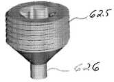
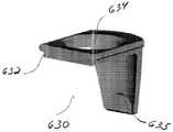
도 15 및 도 16과 관련하여 전술된 단일 부품 뼈 고정 커플링 요소(510)와 대비하여, 뼈 고정 커플링 요소들은 대안적으로 도 17a 내지 도 17g에 가장 잘 도시된 바와 같이, 다중-부품 형태의 뼈 고정 커플링 요소(610)일 수 있다. 다중-부품 뼈 고정 커플링 요소(610)는 하우징(620)과 슬라이더(630)를 포함할 수 있고, 슬라이더(630)는 하우징(620)에 의해 미끄러지게 수납되도록 구성된다. 바람직하게, 도시된 바와 같이, 하우징(620)은 슬라이더(630)에 형성된 돌기(632)를 미끄러지게 수납하기 위한 리세스(622)를 포함하므로 슬라이더(630)와 하우징(620)은 더브테일 조인트 형태의 연결에 의해 상호 연결될 수 있다. 도시된 바와 같이, 하우징(620)은 또한 세트 스크류(625)를 수납하기 위한 나사가 형성된 구멍(624)을 포함할 수 있고, 세트 스크류(620)는 뼈 고정 요소(10)의 밀폐 캡(40)의 드라이브 리세스(42)에서 트랜스컨넥터의 센터링을 위해 그에 형성된 포스트(post)(626)을 포함한다. 슬라이더(630)는 또한 포스트(626)가 그곳을 관통시키기 위해 그에 형성된 관통 구멍(634)을 포함할 수 있다. 이것은 바람직하게 세트 스크류(625)의 적어도 일 부분이 슬라이더(630)를 관통하여 움직이는 것을 허용한다.In contrast to the single part bone
도 17f 및 도 17g에 가장 잘 도시된 바와 같이, 사용 시, 슬라이더(630)는 하우징(620) 내부에 미끄러지게 수납될 수 있고 세트 스크류(625)는 하우징(620)에 형성된 나사 구멍(624)에 대향되어 나사 결합될 수 있다. 개방된 위치에서, 도 17f에 가장 잘 도시된 바와 같이, 뼈 고정 커플링 요소(610)는 뼈 고정 요소(10)의 본체부(20) 위에 느슨하게 배치될 수 있으므로 하우징(620)에 형성된 돌기(635)는 뼈 고정 요소(10)의 본체부(20)의 일 측면에 형성된 리세스(35)와 결합될 수 있다. 그러나, 개방 위치에서, 슬라이더(630)에 형성된 돌기(635)는 본체부(20)의 다른 측면에 형성된 리세스(35)와 결합되지 않을 수 있다. 대안적으로, 슬라이더(630)에 형성된 돌기(635)는 본체부(20)에 형성된 리세스(35)와 결합될 수 있는 한편 하우징(620)에 형성된 돌기(635)는 본체부(20)에 형성된 리세스(35)와 결합하지 않을 수 있다. 대안적으로, 하우징(620)과 슬라이더(630)에 형성된 그 어떤 돌기(635)도 본체부(20)에 형성된 리세스(35)와 결합하지 않을 수 있다. 하우징(620) 속으로 세트 스크류(625)를 회전시키면, 세트 스크류(625),바람직하게 세트 스크류(635)의 원뿔형 바닥면은 슬라이더(630), 바람직하게 슬라이더(630)에 형성된 관통 구멍(634)의 경계에 접촉하게 된다. 그 후, 세트 스크류(625)의 연속된 회전은 슬라이더(630)가 하우징(620)에 대해 당겨지게 하고 슬라이더(630)가 뼈 고정 요소(10)의 본체부(20) 쪽으로 움직이게 한다. 도 17g에 가장 잘 도시된 바와 같이, 세트 스크류(625)가 하우징(620)에 대해 완전히 결합될 때, 슬라이더(630)에 형성된 돌기(635)는 뼈 고정 요소(10)의 본체부(20)의 타 측면에 형성된 리세스(35)와 결합할 수 있으므로 뼈 고정 요소(10)에 대한 뼈 고정 커플링 부재(610)의 위치를 고정하게 된다.As best shown in FIGS. 17F and 17G, in use, the
하우징(620)과 슬라이더(630)는 바람직하게 서로에 대하여 하우징(620)과 슬라이더(630)의 분해를 방지하기 위한 메커니즘을 가지도록 구성된다. 상기 메커니즘은 예를 들어, 슬라이더(630)가 그 안에 위치되는 동안 더브테일 리세스를 통해 측면으로부터 하우징(620)을 변형시키는 것을 포함하는 공지된 그 어떤 메커니즘일 수 있다.The
뼈 고정 커플링 요소들은 또한 다른 방식으로 뼈 고정 요소들(10)의 본체부(20)에 직접 결합될 수 있다. 예를 들어, 도 18a 및 도 18b에 도시된 바와 같이, 뼈 고정 커플링 요소(710)는 모든 자유도들이 단일 스크류(725)의 조임을 통해 고정되게 유지되는 그러한 방식으로 제공될 수 있다. 즉, 이 실시예에 있어서, 바람직하게 뼈 고정 커플링 요소(710)에 대한 브리지 부재(750)의 이동과 뼈 고정 요소(10)에 대한 세로 척추 봉(45)의 이동은 본체부(25)에 대한 단일 스크류(725)의 회전에 의해 고정되게 확보된다.The bone fixation coupling elements can also be directly coupled to the
도시된 바와 같이, 브리지 부재(750)는 그 하나의 끝단의 한 쌍의 작은 구멍들(754)을 가진 강성 바아(solid bar)(752)로서 형성될 수 있다. 작은 구멍들(754)은 뼈 고정 커플링 요소(710)를 수납하도록 구성된다. 브리지 부재(750)는 예를 들어 브리지 부재(750)가 플레이트, 봉 등의 다른 형태로 제공될 수 있음을 주의해야 한다.As shown, the bridge member 750 may be formed as a
뼈 고정 커플링 요소(710)는 하우징(720)의 형태일 수 있으며 하우징(720)은 뼈 고정 요소(10)의 본체부(20)를 수납하도록 구성된다. 하우징은 도 15 및 도 16과 관련하여 전술한 단일 부품 또는 도 17a 내지 도 17g와 관련하여 전술한 2-부품 하우징(720) 형태일 수 있다.The bone
뼈 고정 커플링 요소(710)는 또한 적어도 부분적으로 그 위에서 확장하는 주변 리세스(circumferential recess)(712)를 포함할 수 있고, 주변 리세스(712)는 브리지 부재(750)에 형성된 작은 구멍들(754)의 어느 하나를 수납하도록 구성된다. 작은 구멍들(754)과 뼈 고정 커플링 요소들(710)은 바람직하게 뼈 고정 커플링 요소(710)가 브리지 부재(750)에 대해 이동하는 것을 허용하도록 구성된다. 사용 시, 브리지 부재(750)에 연결된 뼈 고정 커플링 요소(710)는 뼈 고정 커플링 요소들(710)에 형성된 돌기(635)를 뼈 고정 요소(10)의 본체부(20)에 형성된 리세스(35)에 정렬시킴에 의해 뼈 고정 요소(10)의 본체부(20)에 일시적으로 위지될 수 있다. 이 위치에서, 브리지 부재(750)는 바람직하게 중간-측면 방향 뿐만 아니라 뼈 고정 요소(10) 주변에서 회전되게 자유롭게 움직일 수 있다. 브리지 부재(750)의 필요한 위치가 얻어지면, 세트 스크류(725)의 회전은 바람직하게 (i) 봉-수납 채널 내부에 안착된 세로 척추 봉에 직접적으로 또는 간접적으로 가해지는 힘에 의해 뼈 고정 커플링 요소(710)의 위치가 뼈 고정 요소(10)에 대해 고정되게 하고, (ii) 브리지 부재(550)에 기대어 하우징(720)을 방사상으로 확장함으로써, 바람직하게 작은 구멍(754)에 맞대어 하우징(720)을 방사상으로 확장함으로써 뼈 고정 커플링 요소(710)의 위치가 브리지 부재(750)에 대해 고정되게 한다.The bone
또 다른 실시예에 있어서, 도 19a 및 도 19b에 가장 잘 도시된 바와 같이, 뼈 고정 커플링 요소(810)는 뼈 고정 요소(10)의 본체부(20)를 수납하도록 구성된 하우징(820)을 포함할 수 있다. 또한, 하우징(820)은 하나 또는 그 이상의 빔 요소 들(beam elements)(822)을 구비할 수 있고, 세트 스크류(825)의 회전 시, 세트 스크류(825)가 빔 요소들(822)을 뼈 고정 요소(10)의 본체부(20), 바람직하게 본체부(20)에 형성된 리세스(35)와 접촉시키도록 빔 요소들(822)이 구성된다. 보다 구체적으로, 세트 스크류(825)의 회전은 하우징(820)이 뼈 고정 요소(10)의 본체부(20)에 대해 상방으로 움직이게 하는 한편 동시에 빔 요소들(822)을 하방 내측으로 움직여 뼈 고정 요소(10)의 본체부(20)에 형성된 리세스(35)에 접촉되게 함으로써, 뼈 고정 요소(10)에 대한 뼈 고정 커플링 요소(810)의 위치를 고정하게 된다.In another embodiment, as best shown in FIGS. 19A and 19B, the bone
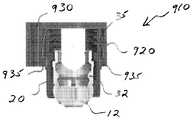
또 다른 실시예에 있어서, 도 20a 및 도 20b에 가장 잘 도시된 바와 같이, 뼈 고정 커플링 요소(910)는 하우징(920)을 포함할 수 있고, 하우징(920)은 뼈 고정 요소(10)의 본체부(20)를 수납하도록 구성된다. 또한, 하우징(920)은 하나 또는 그 이상의 슬라이드 요소들(930)을 수납하기 위한 리세스(922)를 포함할 수 있고, 여기서 슬라이드 요소들(930)의 삽입은 하우징(920)을 뼈 고정 요소(10), 바람직하게 뼈 고정 요소(10)의 본체부(20)에 형성된 리세스(35)와 결합하기 위해 하우징(920)에 형성된 돌기(935)와 결합시킨다. 보다 상세하게, 도시된 바와 같이, 이 실시예에 있어서, 도 19a 및 도 19b의 세트 스크류(825)는 하나 또는 그 이상의 슬라이드 요소들(slide elements)(930)에 의해 대체되고, 여기서 슬라이드 요소(930)의 하방 이동은 하우징(920)을 뼈 고정 요소(10)의 본체부(20)와 결합시키게 한다.In another embodiment, as best shown in FIGS. 20A and 20B, the bone
또 다른 실시예에 있어서, 도 21a 및 도 21b에 가장 잘 도시된 바와 같이, 브리지 부재(1050)는 뼈 고정 커플링 요소(1010)와 일체로 형성될 수 있다. 보다 상세하게, 도시된 바와 같이, 브리지 부재(1050)는 세트 스크류(1025)를 수납하기 위한 나사가 형성된 보어(1062)를 가진 돌출부(1060)를 포함할 수 있다. 세트 스크류(1025)는 뼈 고정 요소(10)의 밀폐 캡(40)과 나사 결합하도록 구성된다. 보다 바람직하게, 도시된 바와 같이, 브리지 부재(1050)에 형성된 돌출부(1060)와 뼈 고정 요소(10)의 밀폐 캡(40)은 상응하는 깎여진(grind) 패턴들(1075)(예, 치차, 톱니, 융기 등)을 가지도록 구성된다. 깎여진 패턴(1075)은 세트 스크류(1025)의 결합 시, 축방향 및 회전 방향 모두의 부가적 고정을 제공하도록 작용한다.In another embodiment, as best shown in FIGS. 21A and 21B, the
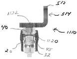
또 다른 실시예에 있어서, 도 22a 및 도 22b에 가장 잘 도시된 바와 같이, 뼈 고정 커플링 요소(1110)는 뼈 고정 요소(10)의 봉-수납 채널(20) 속으로 삽입되도록 구성된 중간 부품(intermediary component)(1120)을 포함할 수 있다. 중간 부품(1120)은 세로 척추 봉(45)과 접촉하도록 구성된다. 중간 부품(1120)은 밀폐 캡(40)을 수납하도록 그 안에 형성된 보어(1122)를 더 구비하므로 밀폐 캡(40)은 뼈 고정 요소(10)의 본체부(20)에 형성된 내부 나사산과 결합된 뼈 고정 요소(10)의 봉-수납 채널(25) 내부에 수납될 수 있다. 밀폐 캡(40)의 회전은 중간 부품(1120)을 세로 척추 봉(45)에 접촉되게 하여 뼈 고정 요소(10)에 대한 세로 척추 봉(45)의 위치 및 뼈 고정 요소(10)에 대한 트랜스컨넥터의 위치를 고정하게 된다.In another embodiment, as best shown in FIGS. 22A and 22B, the bone
또 다른 실시예에 있어서, 도 23에 가장 잘 도시된 바와 같이, 뼈 고정 커플링 요소(1210)는 뼈 고정 요소(10)의 본체부(20)를 수납하도록 구성된 하우징(1220)을 포함할 수 있다. 하우징(1220)은 바람직하게 간섭 또는 가압 고정 형태의 연결에 의해 뼈 고정 요소(10)의 본체부(20)를 수납하도록 구성된다. 뼈 고정 커플링 요소(1210)는 또한 록킹 부품(1230)을 포함할 수 있고, 록킹 부품(1230)은 제1 위치로부터 제2 위치까지 하우징(1220)에 대해 미끄러지게 움직일 수 있으며, 여기서, 뼈 고정 커플링 요소(1210)가 뼈 고정 요소(10)에 대해 느슨해지는 것을 방지하기 위해 추가적인 보장 및/또는 단단함을 제공하기 위해, 제2 위치에서 록킹 부품(1230)은 하우징(1220)을 뼈 고정 요소(10)의 본체부(20)와 결합하도록 더 가압한다.In another embodiment, as best shown in FIG. 23, the bone
또 다른 실시예에 있어서, 도 24에 가장 잘 도시된 바와 같이, 뼈 고정 커플링 요소(1310)는 뼈 고정 요소(10)의 본체부(20)를 수납하도록 구성된 하우징(1320)을 포함할 수 있다. 뼈 고정 요소(10)의 본체부(20)는 바람직하게 그 안에 형성된 그루브(1335)를 포함하고, 구르부(1335)는 바람직하게 본체부(20)의 상부 표면으로부터 확장한다. 그루브(1335)는 하우징(1310)을 미끄러지게 수납하도록 구성된다. 바람직하게, 그루브(1335)는 하우징(1320)에 형성된 텅(1330)을 미끄러지게 수납하도록 구성된다. 이러한 방식으로, 하우징(1320)과 뼈 고정 요소(10)의 본체부(20)는 키(key)-형태 또는 텅과 그루브 형태의 장치를 통해 결합될 수 있다. 뼈 고정 커플링 요소(1310)는 또한 세트 스크류(1325)를 포함할 수 있으므로, 세트 스크류(1325)와 하우징(1320) 및/또는 뼈 고정 요소(10)의 회전 및/또는 결합은 뼈 고정 커플링 요소(1310)가 뼈 고정 요소(10)에 대해 느슨해지는 것을 방지하기 위한 추가적인 보장 및/또는 단단함을 제공할 수 있다. 세트 스크류(1325)의 회전은 하우징(1320)을 약간 상방으로 움직이게 하여 하우징(1320)에 형성된 돌기가 뼈 고정 요소(10)의 본체부(20)에 형성된 리세스(35)에 결합되게 된다.In another embodiment, as best shown in FIG. 24, the bone
또 다른 실시예에 있어서, 도 25에 가장 잘 도시된 바와 같이, 뼈 고정 커플 링 요소(1410)는 뼈 고정 요소(10)의 본체부(20)를 수납하도록 구성된 하우징(1420)을 포함할 수 있다. 하우징(1420)은 바람직하게 서로 바이어스된 한 쌍의 핑거들(1422)을 포함하므로, 핑거들(1422)은 스냅 고정 형태의 장치에 의해 뼈 고정 요소(10)의 본체부(20)와 결합할 수 있다. 보다 바람직하게, 핑거들(1422)은 각각 바람직하게 뼈 고정 요소(10)의 본체부(20)에 형성된 리세스(35)에 결합 및/또는 스냅 고정하기 위해 그 위에 형성된 돌기(1435)를 포함한다. 뼈 고정 커플링 요소(1410)는 뼈 고정 요소(1410)를, 따라서 브리지 부재를 뼈 고정 요소(10)에 더 고정시키기 위해 하우징(1420) 및/또는 뼈 고정 요소(10)를 나사 결합시키기 위한 세트 스크류(미도시)를 더 포함할 수 있다.In another embodiment, as best shown in FIG. 25, bone fixation coupling element 1410 may include a
뼈 고정 요소의 본체부에 형성된 하나 또는 그 이상의 리세스들과의 결합을 위해 뼈 고정 커플링 요소는 그 위에 형성된 하나 또는 그 이상의 돌기들을 포함하는 것처럼 개시 및 도시되었지만, 뼈 고정 커플링 요소는 뼈 고정 요소에 형성된 하나 또는 그 이상의 돌기들과 결합하기 위한 하나 또는 그 이상의 리세스들을 가지도록 구성될 수 있음을 유의해야 한다.Although the bone fixation coupling element has been disclosed and illustrated as including one or more protrusions formed thereon for engagement with one or more recesses formed in the body portion of the bone fixation element, the bone fixation coupling element is a bone It should be noted that it may be configured to have one or more recesses for engaging with one or more protrusions formed in the fixing element.
또한, 비록 뼈 고정 커플링 요소들의 몇몇 실시예들은 세로 척추 봉이 밀폐 캡을 통해 이미 뼈 고정 요소의 봉-수납 채널 내부에 고정되게 확보된 뼈 고정 요소들과 함께 사용되고, 다른 실시예들은 세로 척추 봉이 밀폐 캡을 통해 뼈 고정 요소의 봉-수납 채널 내부에 고정되게 확보되지 않은 뼈 고정 요소들과 함께 사용되는 것으로서 설명되었지만, 다양한 뼈 고정 커플링 요소들의 설계들이 변형 및/또는 개조됨으로써 밀폐 캡이 모든 실시예들에서 더 이상 필요하지 않을 수 있고 그 반대의 경우도 가능함을 고려할 수 있다.Furthermore, although some embodiments of bone fixation coupling elements are used with bone fixation elements that have been secured to have a longitudinal spinal rod already secured inside a rod-storing channel of the bone fixation element via a closure cap, other embodiments have a longitudinal spinal rod Although described as being used with bone fixation elements that are not secured to be secured inside the rod-storage channel of the bone fixation element through the closure cap, the designs of the various bone fixation coupling elements have been modified and / or modified so that the closure cap is It is contemplated that embodiments may no longer be needed and vice versa.
당업자에 의해 평가되는 바와 같이, 예를 들어, 브리지 부재, 뼈 고정 커플링 요소들 등과 같이, 본 명세서에서 설명된 그 어떤 또는 모든 부품들은 세트 또는 키트 형태로 제공될 수 있으므로 외과의사는 고정 시술을 수행하기 위해 부품들의 여러가지 조합들을 선택하여 환자의 특정한 요구/해부학적 구조에 적합하도록 구성된 고정 시스템을 생성할 수 있다. 하나 또는 그 이상의 각각의 구성요소는 키트 또는 세트 형태로 제공될 수 있음을 유의해야 한다. 어떤 키트 또는 세트에 있어서, 동일한 구성요소는 다른 모양 및/또는 크기로 제공될 수 있다.As assessed by one of ordinary skill in the art, any or all of the parts described herein, such as, for example, bridge members, bone fixation coupling elements, etc., may be provided in the form of sets or kits, so the surgeon performs the fixation procedure. Various combinations of parts can be selected to create a fixed system configured to suit the particular needs / anatomical structure of the patient. It should be noted that one or more of each of the components may be provided in a kit or set form. In some kits or sets, the same components may be provided in different shapes and / or sizes.
전술한 상세한 설명과 도면들은 본 발명의 바람직한 실시예들을 나타내지만, 첨부된 청구범위에 정의된 바와 같이 본 발명의 범위 및 정신을 벗어나지 않는 한 다양한 부가, 변형, 조합 및/또는 대체들이 가능함을 이해해야 한다. 예를 들어, 여러가지의 브리지 부재들 및/또는 뼈 고정 커플링 요소들이 본 명세서에서 설명되었지만, 모든 브리지 부재가 각각 그리고 모든 뼈 고정 커플링 요소와 함께 사용될 수 있도록 다른 브리지 부재들 및 뼈 고정 커플링 요소들이 혼합 또는 조화될 수 있음을 고려해야 한다. 예를 들어, 도 1 내지 도 14의 브리지 부재들은 도 15 내지 도 25에 개시된 뼈 고정 커플링 요소들과 함께 사용될 수 있다. 유사하게, 도 15 내지 도 25의 브리지 부재들은 도 1 내지 도 14의 뼈 고정 커플링 요소와 함께 사용될 수 있다. 특히, 본 발명은 그 특징의 정신과 본질을 벗어나지 않고 다른 구성요소들, 물질, 부품들과 함께 다른 특정한 형태, 구조, 배열, 비례에 구체화 될 수 있음은 당업자에게 명백할 것이다. 본 발명은 발명의 원칙을 벗어나지 않는 범위에서 특정의 환경 및 작동 조건들에 특히 적합한 구조, 배열, 비례, 부품들의 많은 변형과 함께 사용될 수 있음을 당업자는 평가할 것이다. 예를 들어, 본 명세서에 개시된 트랜스컨넥터는 중간-측면 및 두개골-꼬리 구성 모두에, 다축 및 단일축 스크류 쌍 모두 또는 그들의 조합에 대한 안정성을 연결 및 제공할 뿐만 아니라 평행 봉 구성에 대한 안정성을 연결 및 제공하는데 사용될 수 있다. 또한, 본 명세서에 개시된 특징들은 단독적으로 또는 다른 특징들과 결합하여 사용될 수 있다. 현재 개시된 실시예들은 따라서 모든 점에서 예시적이고 비제한적인 것으로 간주되어야 하며, 본 발명의 범위는 청구범위에 의해 정의되며, 전술한 상세한 설명에 한정되는 것은 아니다.While the foregoing description and drawings illustrate preferred embodiments of the invention, it should be understood that various additions, modifications, combinations and / or substitutions are possible without departing from the scope and spirit of the invention as defined in the appended claims. do. For example, although various bridge members and / or bone fixation coupling elements have been described herein, other bridge members and bone fixation couplings can be used so that all bridge members can be used with each and all bone fixation coupling elements. It should be taken into account that the elements may be mixed or harmonized. For example, the bridge members of FIGS. 1-14 can be used with the bone fixation coupling elements disclosed in FIGS. 15-25. Similarly, the bridge members of FIGS. 15-25 can be used with the bone fixation coupling element of FIGS. 1-14. In particular, it will be apparent to those skilled in the art that the present invention may be embodied in other specific forms, structures, arrangements, proportions with other components, materials, and components without departing from the spirit and essence of the features. Those skilled in the art will appreciate that the present invention can be used with many modifications of structure, arrangement, proportions, and components that are particularly suited to particular environments and operating conditions without departing from the principles of the invention. For example, the transconnectors disclosed herein connect and provide stability to both parallel and uniaxial screw pairs, as well as to both mid-side and skull-tail configurations, as well as to stability in parallel rod configurations. And to provide. In addition, the features disclosed herein may be used alone or in combination with other features. The presently disclosed embodiments are therefore to be considered in all respects as illustrative and not restrictive, the scope of the invention being defined by the claims, and not limited to the foregoing description.
Claims (25)
Translated fromKoreanApplications Claiming Priority (3)
| Application Number | Priority Date | Filing Date | Title |
|---|---|---|---|
| US82701606P | 2006-09-26 | 2006-09-26 | |
| US60/827,016 | 2006-09-26 | ||
| PCT/US2007/079426WO2008039777A2 (en) | 2006-09-26 | 2007-09-25 | Transconnector |
Publications (2)
| Publication Number | Publication Date |
|---|---|
| KR20090078784Atrue KR20090078784A (en) | 2009-07-20 |
| KR101360009B1 KR101360009B1 (en) | 2014-02-06 |
Family
ID=39106356
Family Applications (1)
| Application Number | Title | Priority Date | Filing Date |
|---|---|---|---|
| KR1020097006553AExpired - Fee RelatedKR101360009B1 (en) | 2006-09-26 | 2007-09-25 | transconnector |
Country Status (13)
| Country | Link |
|---|---|
| US (2) | US8277489B2 (en) |
| EP (1) | EP2073732B1 (en) |
| JP (1) | JP5187594B2 (en) |
| KR (1) | KR101360009B1 (en) |
| CN (1) | CN101568308B (en) |
| AT (1) | ATE486534T1 (en) |
| AU (1) | AU2007300144A1 (en) |
| BR (1) | BRPI0716962A2 (en) |
| CA (1) | CA2664591C (en) |
| CO (1) | CO6180488A2 (en) |
| DE (1) | DE602007010333D1 (en) |
| WO (1) | WO2008039777A2 (en) |
| ZA (1) | ZA200902128B (en) |
Families Citing this family (148)
| Publication number | Priority date | Publication date | Assignee | Title |
|---|---|---|---|---|
| US7833250B2 (en) | 2004-11-10 | 2010-11-16 | Jackson Roger P | Polyaxial bone screw with helically wound capture connection |
| US7862587B2 (en) | 2004-02-27 | 2011-01-04 | Jackson Roger P | Dynamic stabilization assemblies, tool set and method |
| US8876868B2 (en) | 2002-09-06 | 2014-11-04 | Roger P. Jackson | Helical guide and advancement flange with radially loaded lip |
| US7621918B2 (en) | 2004-11-23 | 2009-11-24 | Jackson Roger P | Spinal fixation tool set and method |
| US7377923B2 (en) | 2003-05-22 | 2008-05-27 | Alphatec Spine, Inc. | Variable angle spinal screw assembly |
| US7766915B2 (en) | 2004-02-27 | 2010-08-03 | Jackson Roger P | Dynamic fixation assemblies with inner core and outer coil-like member |
| US8366753B2 (en) | 2003-06-18 | 2013-02-05 | Jackson Roger P | Polyaxial bone screw assembly with fixed retaining structure |
| US8926670B2 (en) | 2003-06-18 | 2015-01-06 | Roger P. Jackson | Polyaxial bone screw assembly |
| US7776067B2 (en) | 2005-05-27 | 2010-08-17 | Jackson Roger P | Polyaxial bone screw with shank articulation pressure insert and method |
| US7967850B2 (en) | 2003-06-18 | 2011-06-28 | Jackson Roger P | Polyaxial bone anchor with helical capture connection, insert and dual locking assembly |
| US7179261B2 (en) | 2003-12-16 | 2007-02-20 | Depuy Spine, Inc. | Percutaneous access devices and bone anchor assemblies |
| US11419642B2 (en) | 2003-12-16 | 2022-08-23 | Medos International Sarl | Percutaneous access devices and bone anchor assemblies |
| US7527638B2 (en) | 2003-12-16 | 2009-05-05 | Depuy Spine, Inc. | Methods and devices for minimally invasive spinal fixation element placement |
| JP2007525274A (en) | 2004-02-27 | 2007-09-06 | ロジャー・ピー・ジャクソン | Orthopedic implant rod reduction instrument set and method |
| US7160300B2 (en) | 2004-02-27 | 2007-01-09 | Jackson Roger P | Orthopedic implant rod reduction tool set and method |
| US11241261B2 (en) | 2005-09-30 | 2022-02-08 | Roger P Jackson | Apparatus and method for soft spinal stabilization using a tensionable cord and releasable end structure |
| US8152810B2 (en) | 2004-11-23 | 2012-04-10 | Jackson Roger P | Spinal fixation tool set and method |
| US8926672B2 (en) | 2004-11-10 | 2015-01-06 | Roger P. Jackson | Splay control closure for open bone anchor |
| US9168069B2 (en) | 2009-06-15 | 2015-10-27 | Roger P. Jackson | Polyaxial bone anchor with pop-on shank and winged insert with lower skirt for engaging a friction fit retainer |
| WO2006057837A1 (en) | 2004-11-23 | 2006-06-01 | Jackson Roger P | Spinal fixation tool attachment structure |
| US8308782B2 (en) | 2004-11-23 | 2012-11-13 | Jackson Roger P | Bone anchors with longitudinal connecting member engaging inserts and closures for fixation and optional angulation |
| US9980753B2 (en) | 2009-06-15 | 2018-05-29 | Roger P Jackson | pivotal anchor with snap-in-place insert having rotation blocking extensions |
| US8444681B2 (en) | 2009-06-15 | 2013-05-21 | Roger P. Jackson | Polyaxial bone anchor with pop-on shank, friction fit retainer and winged insert |
| WO2006058221A2 (en) | 2004-11-24 | 2006-06-01 | Abdou Samy M | Devices and methods for inter-vertebral orthopedic device placement |
| US7901437B2 (en) | 2007-01-26 | 2011-03-08 | Jackson Roger P | Dynamic stabilization member with molded connection |
| US8100946B2 (en) | 2005-11-21 | 2012-01-24 | Synthes Usa, Llc | Polyaxial bone anchors with increased angulation |
| CA2664591C (en) | 2006-09-26 | 2014-12-02 | Synthes Usa, Llc | Transconnector |
| CA2670988C (en) | 2006-12-08 | 2014-03-25 | Roger P. Jackson | Tool system for dynamic spinal implants |
| US10792074B2 (en) | 2007-01-22 | 2020-10-06 | Roger P. Jackson | Pivotal bone anchor assemly with twist-in-place friction fit insert |
| US8568453B2 (en)* | 2007-01-29 | 2013-10-29 | Samy Abdou | Spinal stabilization systems and methods of use |
| WO2008131084A2 (en) | 2007-04-17 | 2008-10-30 | K2M, Inc. | Minimally open interbody access retraction device and surgical method |
| US8979904B2 (en) | 2007-05-01 | 2015-03-17 | Roger P Jackson | Connecting member with tensioned cord, low profile rigid sleeve and spacer with torsion control |
| US9439681B2 (en) | 2007-07-20 | 2016-09-13 | DePuy Synthes Products, Inc. | Polyaxial bone fixation element |
| US9060813B1 (en) | 2008-02-29 | 2015-06-23 | Nuvasive, Inc. | Surgical fixation system and related methods |
| EP2265202B1 (en)* | 2008-04-22 | 2012-08-29 | Synthes GmbH | Bone fixation element with reduction tabs |
| US9504494B2 (en)* | 2008-04-28 | 2016-11-29 | DePuy Synthes Products, Inc. | Implants for securing spinal fixation elements |
| EP2299918B1 (en) | 2008-04-30 | 2017-03-22 | Moximed, Inc. | Mounts for implantable extra-articular systems |
| US8313487B2 (en)* | 2008-06-24 | 2012-11-20 | Extremity Medical Llc | Fixation system, an intramedullary fixation assembly and method of use |
| US8328806B2 (en)* | 2008-06-24 | 2012-12-11 | Extremity Medical, Llc | Fixation system, an intramedullary fixation assembly and method of use |
| AU2010260521C1 (en) | 2008-08-01 | 2013-08-01 | Roger P. Jackson | Longitudinal connecting member with sleeved tensioned cords |
| US20100049252A1 (en)* | 2008-08-21 | 2010-02-25 | Southern Spine, Llc | Transverse Connector Device for Extending an Existing Spinal Fixation System |
| JP5815407B2 (en) | 2008-09-12 | 2015-11-17 | ジンテス ゲゼルシャフト ミット ベシュレンクテル ハフツング | Spinal stabilization and guided fixation system |
| KR20110081208A (en) | 2008-09-29 | 2011-07-13 | 신세스 게엠바하 | Multi-Axis Bottom-Loading Screw and Rod Assemblies |
| US20100087864A1 (en)* | 2008-10-03 | 2010-04-08 | Assaf Klein | Fastener assembly that fastens to polyaxial pedicle screw |
| US20100087867A1 (en)* | 2008-10-03 | 2010-04-08 | Assaf Klein | Fastener assembly that fastens to pedicle screw |
| CA2742399A1 (en) | 2008-11-03 | 2010-06-03 | Dustin M. Harvey | Uni-planar bone fixation assembly |
| US8246665B2 (en)* | 2008-12-22 | 2012-08-21 | Life Spine, Inc. | Posterior cervical cross connector assemblies |
| KR20120013312A (en) | 2009-04-15 | 2012-02-14 | 신세스 게엠바하 | Orthodontic Connectors for Spinal Structures |
| EP2421454A4 (en)* | 2009-04-23 | 2013-12-11 | Spinal Elements Inc | Transverse connectors |
| US9668771B2 (en) | 2009-06-15 | 2017-06-06 | Roger P Jackson | Soft stabilization assemblies with off-set connector |
| US8998959B2 (en) | 2009-06-15 | 2015-04-07 | Roger P Jackson | Polyaxial bone anchors with pop-on shank, fully constrained friction fit retainer and lock and release insert |
| CN103826560A (en) | 2009-06-15 | 2014-05-28 | 罗杰.P.杰克逊 | Polyaxial Bone Anchor with Socket Stem and Winged Inserts with Friction Fit Compression Collars |
| US11229457B2 (en) | 2009-06-15 | 2022-01-25 | Roger P. Jackson | Pivotal bone anchor assembly with insert tool deployment |
| CA2764841A1 (en) | 2009-06-17 | 2010-12-23 | Synthes Usa, Llc | Revision connector for spinal constructs |
| WO2011004222A1 (en)* | 2009-07-10 | 2011-01-13 | Kamil Bal | Pedicular screw system |
| EP2485654B1 (en) | 2009-10-05 | 2021-05-05 | Jackson P. Roger | Polyaxial bone anchor with non-pivotable retainer and pop-on shank, some with friction fit |
| US8870923B2 (en)* | 2009-11-06 | 2014-10-28 | Marc E. Richelsoph | Rod to rod connector with load sharing |
| US8764806B2 (en) | 2009-12-07 | 2014-07-01 | Samy Abdou | Devices and methods for minimally invasive spinal stabilization and instrumentation |
| EP2555696B1 (en)* | 2010-04-08 | 2017-07-26 | Globus Medical, Inc. | Jointed rod |
| US12383311B2 (en) | 2010-05-14 | 2025-08-12 | Roger P. Jackson | Pivotal bone anchor assembly and method for use thereof |
| US9198696B1 (en) | 2010-05-27 | 2015-12-01 | Nuvasive, Inc. | Cross-connector and related methods |
| US20120271353A1 (en)* | 2010-08-16 | 2012-10-25 | Mark Barry | System and method for aligning vertebrae in the amelioration of aberrant spinal column deviation conditions in patients requiring the accomodation of spinal column growth or elongation |
| US8523911B2 (en)* | 2010-09-16 | 2013-09-03 | Globus Medical, Inc. | Transverse connector including locking cap with bearing surface |
| US9301787B2 (en)* | 2010-09-27 | 2016-04-05 | Mmsn Limited Partnership | Medical apparatus and method for spinal surgery |
| US8834540B2 (en)* | 2010-10-20 | 2014-09-16 | Alphatec Spine, Inc. | Polyaxial bone screw with lateral connector |
| US8414623B2 (en)* | 2010-10-29 | 2013-04-09 | Warsaw Orthopedic, Inc. | Connector for connecting elongated members |
| AU2011324058A1 (en) | 2010-11-02 | 2013-06-20 | Roger P. Jackson | Polyaxial bone anchor with pop-on shank and pivotable retainer |
| US20120130436A1 (en)* | 2010-11-23 | 2012-05-24 | Aesculap Implant Systems, Llc | Head to head connector for bone fixation assemblies |
| US20120203278A1 (en)* | 2011-02-04 | 2012-08-09 | Warsaw Orthopedic, Inc. | Crosslink Devices for a Growing Spinal Column Segment |
| US20120203279A1 (en)* | 2011-02-08 | 2012-08-09 | Alphatec Spine, Inc. | Systems and methods for correcting spinal deformities |
| US20120221056A1 (en)* | 2011-02-24 | 2012-08-30 | Alphatec Spine, Inc. | Apparatus for linking implants and reducing deformities |
| US9387013B1 (en) | 2011-03-01 | 2016-07-12 | Nuvasive, Inc. | Posterior cervical fixation system |
| US9247964B1 (en)* | 2011-03-01 | 2016-02-02 | Nuasive, Inc. | Spinal Cross-connector |
| US8672978B2 (en) | 2011-03-04 | 2014-03-18 | Zimmer Spine, Inc. | Transverse connector |
| JP5865479B2 (en) | 2011-03-24 | 2016-02-17 | ロジャー・ピー・ジャクソン | Multiaxial bone anchor with compound joint and pop-mounted shank |
| CA2831081A1 (en) | 2011-04-07 | 2012-10-11 | Mike Hammer | Clamp for spinal cross connecting device |
| US8845728B1 (en) | 2011-09-23 | 2014-09-30 | Samy Abdou | Spinal fixation devices and methods of use |
| US8556942B2 (en) | 2011-12-30 | 2013-10-15 | Blackstone Medical, Inc. | Occipito-cervical fixation assembly and method for constructing same |
| US8945186B2 (en)* | 2011-12-30 | 2015-02-03 | Blackstone Medical, Inc. | Multi-axial spinal cross connecting device |
| US8911479B2 (en) | 2012-01-10 | 2014-12-16 | Roger P. Jackson | Multi-start closures for open implants |
| US9254149B2 (en)* | 2012-01-18 | 2016-02-09 | Neurosurj Research and Development, LLC | Spinal fixation method and apparatus |
| US20130226240A1 (en) | 2012-02-22 | 2013-08-29 | Samy Abdou | Spinous process fixation devices and methods of use |
| WO2013192489A1 (en)* | 2012-06-21 | 2013-12-27 | Aesculap Implant Systems, Llc | Low profile bone stabilization systems |
| US9510866B2 (en)* | 2012-08-15 | 2016-12-06 | Blackstone Medical, Inc. | Pivoting spinal fixation devices |
| US9198767B2 (en) | 2012-08-28 | 2015-12-01 | Samy Abdou | Devices and methods for spinal stabilization and instrumentation |
| EP2712560B1 (en)* | 2012-09-07 | 2014-12-24 | K2M, Inc. | Growing spinal rod system |
| US20140074169A1 (en)* | 2012-09-13 | 2014-03-13 | Warsaw Orthopedic, Inc. | Spinal correction system and method |
| US9320617B2 (en) | 2012-10-22 | 2016-04-26 | Cogent Spine, LLC | Devices and methods for spinal stabilization and instrumentation |
| EP2911599B1 (en)* | 2012-10-23 | 2020-04-29 | Nexus Spine, L.L.C. | Surgical construct coupling system |
| EP2724679A1 (en)* | 2012-10-23 | 2014-04-30 | Nexus Spine, L.L.C. | Transverse connector and related methods |
| US9023087B2 (en)* | 2012-11-09 | 2015-05-05 | Blackstone Medical, Inc. | Percutaneous modular head-to-head cross connector |
| CN103800058A (en)* | 2012-11-14 | 2014-05-21 | 天津市新中医疗器械有限公司 | Adjustable pressurizing lengthening device |
| US8911478B2 (en) | 2012-11-21 | 2014-12-16 | Roger P. Jackson | Splay control closure for open bone anchor |
| US10058354B2 (en) | 2013-01-28 | 2018-08-28 | Roger P. Jackson | Pivotal bone anchor assembly with frictional shank head seating surfaces |
| US8852239B2 (en) | 2013-02-15 | 2014-10-07 | Roger P Jackson | Sagittal angle screw with integral shank and receiver |
| US20140277146A1 (en)* | 2013-03-15 | 2014-09-18 | Blackstone Medical, Inc. | Cross-braced bilateral spinal rod connector |
| WO2014172445A1 (en)* | 2013-04-17 | 2014-10-23 | Ebi, Llc | Cross connector system |
| WO2015023420A2 (en) | 2013-07-25 | 2015-02-19 | Latitude Holdings, Llc | Percutaneous pedicle screw revision system |
| US9566092B2 (en) | 2013-10-29 | 2017-02-14 | Roger P. Jackson | Cervical bone anchor with collet retainer and outer locking sleeve |
| US9717533B2 (en) | 2013-12-12 | 2017-08-01 | Roger P. Jackson | Bone anchor closure pivot-splay control flange form guide and advancement structure |
| US9451993B2 (en) | 2014-01-09 | 2016-09-27 | Roger P. Jackson | Bi-radial pop-on cervical bone anchor |
| US9707015B2 (en) | 2014-01-14 | 2017-07-18 | Life Spine, Inc. | Implant for immobilizing cervical vertebrae |
| US20170065302A9 (en)* | 2014-03-11 | 2017-03-09 | Warsaw Orthopedic, Inc. | Spinal construct and method |
| US9597119B2 (en) | 2014-06-04 | 2017-03-21 | Roger P. Jackson | Polyaxial bone anchor with polymer sleeve |
| US10064658B2 (en) | 2014-06-04 | 2018-09-04 | Roger P. Jackson | Polyaxial bone anchor with insert guides |
| BR112017005408B1 (en)* | 2014-09-19 | 2022-05-10 | Duet Spine Holdings, Llc | Single-level fusion system and assembly method thereof |
| EP3193755B1 (en) | 2014-09-19 | 2022-02-09 | In Queue Innovations, LLC | Fusion systems of assembly and use |
| US20160128734A1 (en)* | 2014-11-11 | 2016-05-12 | Intrepid Orthopedics | Threaded Setscrew Crosslink |
| CA2917676A1 (en)* | 2015-01-13 | 2016-07-13 | Stryker European Holdings I, Llc | Growing rods and methods of use |
| FR3034979B1 (en)* | 2015-04-17 | 2021-08-27 | Implanet | DEVICE, SYSTEM AND METHOD FOR FIXING A SPINAL VERTEBRA ON A ROD. |
| US9763703B2 (en) | 2015-05-05 | 2017-09-19 | Degen Medical, Inc. | Cross connectors, kits, and methods |
| US20170079687A1 (en)* | 2015-09-22 | 2017-03-23 | Eric Oberlander | Articulating spinal crosslink apparatus |
| US10857003B1 (en) | 2015-10-14 | 2020-12-08 | Samy Abdou | Devices and methods for vertebral stabilization |
| US9603634B1 (en) | 2015-11-13 | 2017-03-28 | Amendia, Inc. | Percutaneous rod-to-rod cross connector |
| WO2017107883A1 (en)* | 2015-12-23 | 2017-06-29 | 马向阳 | Screw-rod fixation device specially used for posterior atlantoaxial vertebrae |
| US10321939B2 (en) | 2016-05-18 | 2019-06-18 | Medos International Sarl | Implant connectors and related methods |
| US10517647B2 (en) | 2016-05-18 | 2019-12-31 | Medos International Sarl | Implant connectors and related methods |
| US10786285B2 (en) | 2016-06-06 | 2020-09-29 | Stryker European Holdings I, Llc | Paraxial revision rod-to-rod connector |
| EP3278751B1 (en) | 2016-07-15 | 2024-03-06 | Stryker European Operations Holdings LLC | Spinal fixation assembly |
| RU170604U1 (en)* | 2016-08-08 | 2017-05-02 | Саидкасим Наркулович Пардаев | MEDICAL INSTRUMENT FOR TEMPORARY STABILIZATION OF THE SPINE WHEN CORRECTING ITS DEFORMATION |
| US10413330B2 (en)* | 2016-08-09 | 2019-09-17 | Warsaw Orthopedic, Inc. | Spinal implant system and method |
| AU2017313725B2 (en) | 2016-08-15 | 2022-09-22 | Triqueue Holdings, Llc | Bone fusion device, system and methods |
| US10973648B1 (en) | 2016-10-25 | 2021-04-13 | Samy Abdou | Devices and methods for vertebral bone realignment |
| US10744000B1 (en) | 2016-10-25 | 2020-08-18 | Samy Abdou | Devices and methods for vertebral bone realignment |
| US10966760B2 (en)* | 2016-10-28 | 2021-04-06 | Warsaw Orthopedic, Inc. | Spinal implant system and method |
| US10398476B2 (en) | 2016-12-13 | 2019-09-03 | Medos International Sàrl | Implant adapters and related methods |
| US10492835B2 (en) | 2016-12-19 | 2019-12-03 | Medos International Sàrl | Offset rods, offset rod connectors, and related methods |
| US10413331B2 (en)* | 2016-12-21 | 2019-09-17 | Spine Wave, Inc. | Spinal stabilization system with head to head cross connector |
| US10238432B2 (en)* | 2017-02-10 | 2019-03-26 | Medos International Sàrl | Tandem rod connectors and related methods |
| US20180228516A1 (en)* | 2017-02-14 | 2018-08-16 | Warsaw Orthopedic, Inc. | Spinal implant system and method |
| US10966761B2 (en) | 2017-03-28 | 2021-04-06 | Medos International Sarl | Articulating implant connectors and related methods |
| US10561454B2 (en) | 2017-03-28 | 2020-02-18 | Medos International Sarl | Articulating implant connectors and related methods |
| US10362982B2 (en) | 2017-04-28 | 2019-07-30 | Warsaw Orthopedic, Inc. | Spinal implant system and method |
| US10258386B2 (en)* | 2017-06-15 | 2019-04-16 | Warsaw Orthopedic, Inc. | Spinal construct and method |
| CN110831530A (en)* | 2017-06-25 | 2020-02-21 | 普利马脊柱有限公司 | Multi-level spinal implant system |
| US10456174B2 (en)* | 2017-07-31 | 2019-10-29 | Medos International Sarl | Connectors for use in systems and methods for reducing the risk of proximal junctional kyphosis |
| US10463403B2 (en) | 2017-07-31 | 2019-11-05 | Medos International Sarl | Systems and methods for reducing the risk of proximal junctional kyphosis using a bone anchor or other attachment point |
| US11076890B2 (en) | 2017-12-01 | 2021-08-03 | Medos International Sàrl | Rod-to-rod connectors having robust rod closure mechanisms and related methods |
| US11446064B2 (en) | 2018-04-26 | 2022-09-20 | Stryker European Operations Holdings Llc | Orthopedic growing devices |
| US10993746B2 (en)* | 2018-05-03 | 2021-05-04 | K2M, Inc. | Head to head transverse connector |
| IT201800009083A1 (en) | 2018-10-02 | 2020-04-02 | Medacta Int Sa | ALIGNMENT DEVICE FOR PERIACETABULAR OSTEOTOMY |
| US11179248B2 (en) | 2018-10-02 | 2021-11-23 | Samy Abdou | Devices and methods for spinal implantation |
| US11653956B2 (en)* | 2018-11-14 | 2023-05-23 | Quandary Medical, Llc | Cross connection system for strengthening a stabilization construct |
| US10893894B2 (en) | 2019-04-24 | 2021-01-19 | Aesculap Implant Systems, Llc | Transverse coupling for surgical implant extensions |
| US11571244B2 (en)* | 2019-05-22 | 2023-02-07 | Nuvasive, Inc. | Posterior spinal fixation screws |
| JP7702694B2 (en)* | 2021-04-08 | 2025-07-04 | ミズホ株式会社 | Percutaneous Spinal Stabilization System |
| US11331125B1 (en) | 2021-10-07 | 2022-05-17 | Ortho Inventions, Llc | Low profile rod-to-rod coupler |
| DE102023105067A1 (en)* | 2023-03-01 | 2024-09-05 | Aesculap Ag | Stabilization bridge for an implant screw and implant screw with a stabilization bridge |
Family Cites Families (136)
| Publication number | Priority date | Publication date | Assignee | Title |
|---|---|---|---|---|
| US2330095A (en) | 1941-11-15 | 1943-09-21 | Thompson Prod Inc | Joint construction |
| PL114098B1 (en) | 1978-04-14 | 1981-01-31 | Wyzsza Szkola Inzynierska | Apparatus for correcting spinal curvature |
| US4258607A (en)* | 1978-05-08 | 1981-03-31 | Microdot Inc. | Vibration resistant screw |
| PL127121B1 (en) | 1980-07-30 | 1983-09-30 | Wyzsza Szkola Inzynierska | Surgical strut for treating spinal affections |
| DE3121272A1 (en) | 1981-05-29 | 1982-12-23 | Ulrich, Max Bernhard, 7900 Ulm | CORRECTIONAL IMPLANT FOR LUMBOSACRAL SPONDYLODESIS |
| DE3219575A1 (en) | 1982-05-25 | 1983-12-01 | Patrick Dr.med. 3590 Bad Wildungen Kluger | Implant system for correction of the position and stabilisation of the spine |
| FR2545350B1 (en) | 1983-05-04 | 1985-08-23 | Cotrel Yves | DEVICE FOR SHRINKAGE OF THE RACHIS |
| US4611582A (en) | 1983-12-27 | 1986-09-16 | Wisconsin Alumni Research Foundation | Vertebral clamp |
| DE3639810C2 (en) | 1986-11-21 | 1998-04-09 | Heinrich Ulrich | Implant for spine correction and / or stabilization |
| FR2615095B1 (en) | 1987-05-15 | 1989-08-18 | Fabrication Materiel Orthopedi | OSTEOSYNTHESIS INSTRUMENTATION FOR THE CORRECTION OF LUMBAR SCOLIOSES BY POSTERIOR PATHWAY |
| GB8718708D0 (en) | 1987-08-07 | 1987-09-16 | Mehdian S M H | Apparatus for treatment of spinal disorders |
| US7534254B1 (en)* | 1988-06-13 | 2009-05-19 | Warsaw Orthopedic, Inc. | Threaded frusto-conical interbody spinal fusion implants |
| FR2633177B1 (en) | 1988-06-24 | 1991-03-08 | Fabrication Materiel Orthopedi | IMPLANT FOR A SPINAL OSTEOSYNTHESIS DEVICE, ESPECIALLY IN TRAUMATOLOGY |
| GB8825909D0 (en) | 1988-11-04 | 1988-12-07 | Showell A W Sugicraft Ltd | Pedicle engaging means |
| US4981406A (en)* | 1988-12-05 | 1991-01-01 | Ford Motor Company | Fastener screw thread and pilot to avoid cross threading |
| GB2254394B (en) | 1988-12-21 | 1993-03-17 | Bristol Myers Squibb Co | Coupler assembly |
| US4955885A (en) | 1988-12-21 | 1990-09-11 | Zimmer, Inc. | Surgical slider instrument and method of using instrument |
| US5084049A (en) | 1989-02-08 | 1992-01-28 | Acromed Corporation | Transverse connector for spinal column corrective devices |
| JPH0620466B2 (en) | 1989-03-31 | 1994-03-23 | 有限会社田中医科器械製作所 | Spinal column correction device |
| FR2645427A1 (en) | 1989-04-11 | 1990-10-12 | Cotrel Yves | Transverse fixing bar for spinal osteosynthesis device |
| US5261913A (en) | 1989-07-26 | 1993-11-16 | J.B.S. Limited Company | Device for straightening, securing, compressing and elongating the spinal column |
| FR2658413B1 (en) | 1990-02-19 | 1997-01-03 | Sofamor | OSTEOSYNTHESIS DEVICE FOR THE CORRECTION OF SPINAL DEVIATIONS. |
| FR2659225B1 (en) | 1990-03-08 | 1995-09-08 | Sofamor | TRANSVERSE FIXING DEVICE FOR PROVIDING A RIGID CROSS-LINK BETWEEN TWO RODS OF A SPINAL OSTEOSYNTHESIS SYSTEM. |
| WO1991016020A1 (en) | 1990-04-26 | 1991-10-31 | Danninger Medical Technology, Inc. | Transpedicular screw system and method of use |
| FR2676354B1 (en)* | 1991-05-17 | 1997-11-07 | Vignaud Jean Louis | LOCKABLE CONNECTION DEVICE OF SPINAL OSTEOSYNTHESIS ANCHORING ELEMENTS. |
| US5209752A (en) | 1991-12-04 | 1993-05-11 | Danek Medical, Inc. | Lateral offset connector for spinal implant system |
| AU659912B2 (en) | 1992-03-10 | 1995-06-01 | Bristol-Myers Squibb Company | Perpendicular rod connector for spinal fixation device |
| US5281222A (en) | 1992-06-30 | 1994-01-25 | Zimmer, Inc. | Spinal implant system |
| US5312405A (en) | 1992-07-06 | 1994-05-17 | Zimmer, Inc. | Spinal rod coupler |
| US5334203A (en) | 1992-09-30 | 1994-08-02 | Amei Technologies Inc. | Spinal fixation system and methods |
| US5275600A (en) | 1992-10-05 | 1994-01-04 | Zimmer, Inc. | Telescoping rod to rod coupler for a spinal system |
| ZA937672B (en) | 1992-10-22 | 1994-05-16 | Danek Medical Inc | Spinal rod transverse connector for supporting vertebral fixation elements |
| US5527314A (en) | 1993-01-04 | 1996-06-18 | Danek Medical, Inc. | Spinal fixation system |
| US5423818A (en) | 1993-02-17 | 1995-06-13 | Danek Medical, Inc. | Clamp for attaching a vertebral fixation element to a spinal rod |
| US5549607A (en) | 1993-02-19 | 1996-08-27 | Alphatec Manufacturing, Inc, | Apparatus for spinal fixation system |
| US5531745A (en) | 1993-03-11 | 1996-07-02 | Danek Medical, Inc. | System for stabilizing the spine and reducing spondylolisthesis |
| FR2709411B1 (en) | 1993-09-03 | 1995-11-17 | Sofamor | Stabilizing forceps of a cervical spinal segment. |
| DE4330837A1 (en) | 1993-09-11 | 1995-03-16 | Michael Hahn | Pedicle screw and internal fixator |
| US5439463A (en) | 1993-11-12 | 1995-08-08 | Lin; Chih-I | Spinal clamping device |
| JP2605313Y2 (en) | 1993-12-28 | 2000-07-10 | 旭光学工業株式会社 | Fixation device for posterior spine correction member |
| FR2714590A1 (en) | 1994-01-05 | 1995-07-07 | Lenfant Jean Pierre | Transverse fixing member for spinal column supporting rods |
| US5522816A (en) | 1994-03-09 | 1996-06-04 | Acromed Corporation | Transverse connection for spinal column corrective devices |
| US5601552A (en) | 1994-03-18 | 1997-02-11 | Sofamor, S.N.C. | Fixing device for a rigid transverse connection device between rods of a spinal osteosynthesis system |
| US5498263A (en) | 1994-06-28 | 1996-03-12 | Acromed Corporation | Transverse connector for spinal column corrective devices |
| US5575791A (en) | 1994-07-27 | 1996-11-19 | Lin; Chih-I | Universal eccentric fixation mechanism for orthopedic surgery |
| US5507746A (en) | 1994-07-27 | 1996-04-16 | Lin; Chih-I | Holding and fixing mechanism for orthopedic surgery |
| US5620443A (en) | 1995-01-25 | 1997-04-15 | Danek Medical, Inc. | Anterior screw-rod connector |
| US5688272A (en) | 1995-03-30 | 1997-11-18 | Danek Medical, Inc. | Top-tightening transverse connector for a spinal fixation system |
| US5716355A (en) | 1995-04-10 | 1998-02-10 | Sofamor Danek Group, Inc. | Transverse connection for spinal rods |
| US5630816A (en) | 1995-05-01 | 1997-05-20 | Kambin; Parviz | Double barrel spinal fixation system and method |
| US5947966A (en) | 1995-06-06 | 1999-09-07 | Sdgi Holdings, Inc. | Device for linking adjacent rods in spinal instrumentation |
| WO1996039090A1 (en)* | 1995-06-06 | 1996-12-12 | Sdgi Holdings, Inc. | Device for linking adjacent rods in spinal instrumentation |
| US5676665A (en) | 1995-06-23 | 1997-10-14 | Bryan; Donald W. | Spinal fixation apparatus and method |
| JP3060284B2 (en)* | 1995-08-22 | 2000-07-10 | マックス株式会社 | Drilling screw |
| US5702392A (en) | 1995-09-25 | 1997-12-30 | Wu; Shing-Sheng | Coupling plate for spinal correction and a correction device of using the same |
| US5693053A (en)* | 1995-10-19 | 1997-12-02 | Sdgi Holdings, Inc. | Variable angle and transitional linking member |
| US5752955A (en) | 1995-10-30 | 1998-05-19 | Fastenetix, L.L.C. | Sliding shaft variable length cross-link device for use with dual rod apparatus |
| US5709684A (en) | 1995-12-04 | 1998-01-20 | Fastenetix, Llc | Advanced compression locking variable length cross-link device |
| US5667507A (en) | 1995-12-04 | 1997-09-16 | Fastenetix, Llc | Compression locking variable length cross-link device for use with dual rod apparatus |
| US5669910A (en) | 1996-01-02 | 1997-09-23 | Pioneer Laboratories, Inc. | Crosslink for implantable rods |
| FR2743712B1 (en) | 1996-01-19 | 1998-04-30 | Louis Rene | POSTERIOR VERTEBRAL OSTEOSYNTHESIS ANCHORING DEVICE |
| FR2748386B1 (en) | 1996-05-09 | 1998-11-20 | Breard Francis Henri | ANTI-TRIP SYSTEM FOR SPINE ARTHRODESIS BAR |
| US5681312A (en) | 1996-05-31 | 1997-10-28 | Acromed Corporation | Spine construct with band clamp |
| FR2749156B1 (en) | 1996-06-03 | 1998-12-04 | Stryker France Sa | DEVICE FOR RIGID TRANSVERSE CONNECTION BETWEEN TWO RODS OF OSTEOSYNTHESIS OF THE RACHIS |
| FR2750033B1 (en) | 1996-06-20 | 1998-09-11 | Euros Sa | DEVICE FOR CROSS-CONNECTION OF RODS OF IMPLANTS |
| US5707372A (en) | 1996-07-11 | 1998-01-13 | Third Millennium Engineering, Llc. | Multiple node variable length cross-link device |
| US5885284A (en) | 1996-07-11 | 1999-03-23 | Third Millennium Engineering, L.L.C. | Hinged variable length cross-link device |
| US6171311B1 (en) | 1996-10-18 | 2001-01-09 | Marc Richelsoph | Transverse connector |
| US6416515B1 (en) | 1996-10-24 | 2002-07-09 | Spinal Concepts, Inc. | Spinal fixation system |
| US6783526B1 (en) | 1997-05-15 | 2004-08-31 | Howmedica Osteonics Corp. | Transverse rod connector clip |
| US5980523A (en) | 1998-01-08 | 1999-11-09 | Jackson; Roger | Transverse connectors for spinal rods |
| US6083226A (en) | 1998-04-22 | 2000-07-04 | Fiz; Daniel | Bone fixation device and transverse linking bridge |
| DE29808593U1 (en) | 1998-05-13 | 1999-09-23 | Howmedica GmbH, 24232 Schönkirchen | Device for connecting two spaced longitudinal rods of a spinal implant |
| US5989251A (en) | 1998-06-17 | 1999-11-23 | Surgical Dynamics, Inc. | Apparatus for spinal stabilization |
| US6264658B1 (en) | 1998-07-06 | 2001-07-24 | Solco Surgical Instruments Co., Ltd. | Spine fixing apparatus |
| CN100376219C (en)* | 1998-07-06 | 2008-03-26 | 株式会社率高 | spinal fixation device |
| US6110173A (en) | 1998-09-15 | 2000-08-29 | Advanced Spine Fixation Systems, Inc. | Transverse connector for spinal fixation systems |
| FR2783411B1 (en) | 1998-09-18 | 2000-12-01 | Eurosurgical | POSTERIOR SPINAL OSTEOSYNTHESIS DEVICE |
| US6355038B1 (en) | 1998-09-25 | 2002-03-12 | Perumala Corporation | Multi-axis internal spinal fixation |
| DE60037352T2 (en) | 1999-03-30 | 2008-11-13 | Howmedica Osteonics Corp. | Apparatus for stabilizing the spine |
| US6234705B1 (en) | 1999-04-06 | 2001-05-22 | Synthes (Usa) | Transconnector for coupling spinal rods |
| US6283967B1 (en) | 1999-12-17 | 2001-09-04 | Synthes (U.S.A.) | Transconnector for coupling spinal rods |
| ES2154227B1 (en) | 1999-06-30 | 2001-11-16 | Surgival Co S A | POLYAXIAL SYSTEM OF FIXATION OF VERTEBRAS. |
| US7122036B2 (en) | 1999-07-01 | 2006-10-17 | Spinevision, S.A. | Connector for an osteosynthesis system intended to provide a connection between two rods of a spinal osteosynthesis system, osteosynthesis system using such a connector, and method of implanting such an osteosynthesis system |
| AU6633900A (en) | 1999-08-12 | 2001-03-13 | Osteotech, Inc. | Rod-to-rod coupler |
| US6238396B1 (en) | 1999-10-07 | 2001-05-29 | Blackstone Medical, Inc. | Surgical cross-connecting apparatus and related methods |
| US6217578B1 (en) | 1999-10-19 | 2001-04-17 | Stryker Spine S.A. | Spinal cross connector |
| CN1191791C (en) | 2000-01-13 | 2005-03-09 | 库尔斯恩蒂斯股份公司 | Device for detachably clamping a longitudinal carrier in a surgical implant |
| US6432108B1 (en) | 2000-01-24 | 2002-08-13 | Depuy Orthopaedics, Inc. | Transverse connector |
| US6261288B1 (en) | 2000-02-08 | 2001-07-17 | Roger P. Jackson | Implant stabilization and locking system |
| US6309391B1 (en) | 2000-03-15 | 2001-10-30 | Sdgi Holding, Inc. | Multidirectional pivoting bone screw and fixation system |
| US6616668B2 (en) | 2000-06-09 | 2003-09-09 | Cross Medical Products, Inc. | Adjustable transverse connector for use with a spinal implant system |
| US6551318B1 (en) | 2000-07-26 | 2003-04-22 | Stahurski Consulting Inc. | Spinal column retaining apparatus |
| US6524310B1 (en) | 2000-08-18 | 2003-02-25 | Blackstone Medical, Inc. | Surgical cross-connecting apparatus having locking lever |
| US6485491B1 (en) | 2000-09-15 | 2002-11-26 | Sdgi Holdings, Inc. | Posterior fixation system |
| US6887241B1 (en) | 2000-10-06 | 2005-05-03 | Spinal Concepts, Inc. | Adjustable transverse connector with cam activated engagers |
| FR2816195B1 (en) | 2000-11-07 | 2003-01-03 | Medicrea | VERTEBRAL ARTHRODESIS MATERIAL |
| JP2002213425A (en)* | 2000-11-14 | 2002-07-31 | Meidoo:Kk | bolt |
| US6602253B2 (en) | 2001-02-12 | 2003-08-05 | Marc Richelsoph | Rod to rod connector |
| US6666638B2 (en)* | 2001-02-15 | 2003-12-23 | Phillips Screw Company | Deck screw having multiple threaded sections |
| US6802844B2 (en) | 2001-03-26 | 2004-10-12 | Nuvasive, Inc | Spinal alignment apparatus and methods |
| US20020143327A1 (en) | 2001-03-27 | 2002-10-03 | Endius Incorporated | Transverse connector for use in spinal corrective surgery |
| US6554832B2 (en)* | 2001-04-02 | 2003-04-29 | Endius Incorporated | Polyaxial transverse connector |
| ATE382298T1 (en) | 2001-04-24 | 2008-01-15 | Coligne Ag | INSTRUMENTS FOR STABILIZING CERTAIN VERTEBRATES OF THE SPINE |
| TW524094U (en) | 2001-05-02 | 2003-03-11 | Jung-Chiuan Ye | Retaining and recovering apparatus for spines |
| JP2002355252A (en) | 2001-05-31 | 2002-12-10 | Kyocera Corp | Cross-link device for vertebral correction rod |
| US6675679B2 (en)* | 2001-07-12 | 2004-01-13 | Dj Technologies, Inc. | Internal gripping pipe wrench |
| US20030045874A1 (en) | 2001-08-31 | 2003-03-06 | Thomas James C. | Transverse connector assembly for spine fixation system |
| US6793657B2 (en) | 2001-09-10 | 2004-09-21 | Solco Biomedical Co., Ltd. | Spine fixing apparatus |
| JP4171631B2 (en)* | 2001-09-25 | 2008-10-22 | 株式会社青山製作所 | bolt |
| US6918727B2 (en)* | 2002-05-01 | 2005-07-19 | Joker Industrial Co., Ltd. | Anchoring screw with double heads and triple threads of different depths of thread |
| US8137386B2 (en)* | 2003-08-28 | 2012-03-20 | Jackson Roger P | Polyaxial bone screw apparatus |
| US7635367B2 (en)* | 2003-08-05 | 2009-12-22 | Medicrea International | Osteosynthesis clip and insertion tool for use with bone tissue fragments |
| US7481827B2 (en) | 2003-10-09 | 2009-01-27 | Synthes (U.S.A.) | Linking transconnector for coupling spinal rods |
| US7213999B2 (en)* | 2004-01-30 | 2007-05-08 | Torque-Traction Technologies, Llc. | Fastener with opposite hand threads for securing two components together |
| US7819902B2 (en) | 2004-02-27 | 2010-10-26 | Custom Spine, Inc. | Medialised rod pedicle screw assembly |
| US7717939B2 (en) | 2004-03-31 | 2010-05-18 | Depuy Spine, Inc. | Rod attachment for head to head cross connector |
| US7645294B2 (en)* | 2004-03-31 | 2010-01-12 | Depuy Spine, Inc. | Head-to-head connector spinal fixation system |
| US20050228377A1 (en)* | 2004-04-07 | 2005-10-13 | Depuy Spine, Inc. | Spinal cross-connectors |
| US8034082B2 (en)* | 2004-07-08 | 2011-10-11 | Globus Medical, Inc. | Transverse fixation device for spinal fixation systems |
| US7794477B2 (en)* | 2004-10-05 | 2010-09-14 | Warsaw Orthopedic, Inc. | Spinal implants and methods with extended multi-axial anchor assemblies |
| EP1830722A2 (en) | 2004-11-19 | 2007-09-12 | Alphaspine, Inc. | Rod-coupling assemblies |
| EP1892426B1 (en)* | 2005-06-13 | 2011-08-10 | Aoyama Seisakusho Co., Ltd. | Use of a guide portion on a bolt |
| DE202006000479U1 (en)* | 2006-01-12 | 2006-03-16 | Abc Verbindungstechnik Gmbh & Co. Kg | Self-piercing and thread-forming screw |
| US8371603B2 (en)* | 2006-03-10 | 2013-02-12 | John R. Columbia | Maximum security/maximum versatility ball mount assembly |
| US20070217887A1 (en)* | 2006-03-16 | 2007-09-20 | Ching-Kuei Lin | Screw |
| US7867255B2 (en)* | 2006-04-07 | 2011-01-11 | Warsaw Orthopedic, Inc. | Spinal rod connector system and method for a bone anchor |
| CA2664591C (en) | 2006-09-26 | 2014-12-02 | Synthes Usa, Llc | Transconnector |
| AU2007301485B2 (en)* | 2006-09-28 | 2012-09-06 | Ogen Innovative Medical Devices Ltd. | Orthopedic bone fixation |
| US7892260B2 (en)* | 2006-10-06 | 2011-02-22 | Depuy Spine, Inc. | Unilateral placement |
| US8439617B2 (en)* | 2007-10-31 | 2013-05-14 | Carl Strom | Self-tapping and self-aligning insert to replace damaged threads |
| US8172280B2 (en)* | 2008-05-16 | 2012-05-08 | Fischer Herbert J | Sheet metal corner for duct flanges |
| DE102008042141A1 (en)* | 2008-09-16 | 2010-03-25 | Kamax-Werke Rudolf Kellermann Gmbh & Co. Kg | Self-centering screw |
| US8246657B1 (en)* | 2009-06-29 | 2012-08-21 | Nuvasive, Inc. | Spinal cross connector |
| US8221466B2 (en)* | 2009-12-23 | 2012-07-17 | Spinecraft, LLC | Transconnector for coupling first and second spinal fixation elements |
| KR101191910B1 (en)* | 2010-07-28 | 2012-10-17 | (주)소프트켐 | Plastic female screw connector using an injection moulding |
- 2007
- 2007-09-25CACA2664591Apatent/CA2664591C/ennot_activeExpired - Fee Related
- 2007-09-25KRKR1020097006553Apatent/KR101360009B1/ennot_activeExpired - Fee Related
- 2007-09-25CNCN2007800435891Apatent/CN101568308B/enactiveActive
- 2007-09-25ATAT07843151Tpatent/ATE486534T1/ennot_activeIP Right Cessation
- 2007-09-25JPJP2009530558Apatent/JP5187594B2/enactiveActive
- 2007-09-25ZAZA200902128Apatent/ZA200902128B/enunknown
- 2007-09-25USUS12/442,647patent/US8277489B2/enactiveActive
- 2007-09-25WOPCT/US2007/079426patent/WO2008039777A2/enactiveApplication Filing
- 2007-09-25AUAU2007300144Apatent/AU2007300144A1/ennot_activeAbandoned
- 2007-09-25DEDE602007010333Tpatent/DE602007010333D1/enactiveActive
- 2007-09-25BRBRPI0716962-0Apatent/BRPI0716962A2/ennot_activeApplication Discontinuation
- 2007-09-25EPEP07843151Apatent/EP2073732B1/enactiveActive
- 2009
- 2009-04-24COCO09041602Apatent/CO6180488A2/enactiveIP Right Grant
- 2012
- 2012-08-30USUS13/598,920patent/US8784452B2/enactiveActive
Also Published As
| Publication number | Publication date |
|---|---|
| KR101360009B1 (en) | 2014-02-06 |
| CO6180488A2 (en) | 2010-07-19 |
| JP2010504833A (en) | 2010-02-18 |
| ATE486534T1 (en) | 2010-11-15 |
| BRPI0716962A2 (en) | 2013-10-29 |
| US8784452B2 (en) | 2014-07-22 |
| CA2664591C (en) | 2014-12-02 |
| US20130006306A1 (en) | 2013-01-03 |
| WO2008039777A3 (en) | 2008-09-18 |
| EP2073732A2 (en) | 2009-07-01 |
| US8277489B2 (en) | 2012-10-02 |
| EP2073732B1 (en) | 2010-11-03 |
| CA2664591A1 (en) | 2008-04-03 |
| US20100094345A1 (en) | 2010-04-15 |
| AU2007300144A1 (en) | 2008-04-03 |
| ZA200902128B (en) | 2010-03-31 |
| CN101568308B (en) | 2011-04-20 |
| CN101568308A (en) | 2009-10-28 |
| JP5187594B2 (en) | 2013-04-24 |
| DE602007010333D1 (en) | 2010-12-16 |
| WO2008039777A2 (en) | 2008-04-03 |
Similar Documents
| Publication | Publication Date | Title |
|---|---|---|
| KR101360009B1 (en) | transconnector | |
| US12089877B2 (en) | Revision connector for spinal constructs | |
| US20230346432A1 (en) | Method of assembling a pivotal bone anchor assembly with snap-in-place bushing | |
| US11813000B2 (en) | Spinal connectors and related methods | |
| US20240023996A1 (en) | Orthopedic tethered implants and system | |
| US11607251B2 (en) | Orthopedic tethered implants and system | |
| US9649134B2 (en) | Uniplanar screw assembly and methods of use | |
| JP5006926B2 (en) | Method and apparatus for interconnecting bone appliers | |
| EP2355725B1 (en) | Bone fixation assembly | |
| US10588668B2 (en) | Articulating rod assembly | |
| US8361120B2 (en) | Outrigger | |
| US20060200128A1 (en) | Bone anchor | |
| KR20020057790A (en) | Pedicle screw assembly | |
| CA2540143A1 (en) | Polyaxial bone screw with torqueless fastening | |
| US20220395301A1 (en) | Laminoplasty plates, systems, and devices, and methods relating to the same | |
| US10687860B2 (en) | Segmental correction of lumbar lordosis | |
| JP2021529583A (en) | Modular screw system with adjustable length | |
| WO2015128811A2 (en) | Segmental correction of lumbar lordosis |
Legal Events
| Date | Code | Title | Description |
|---|---|---|---|
| E13-X000 | Pre-grant limitation requested | St.27 status event code:A-2-3-E10-E13-lim-X000 | |
| PA0105 | International application | St.27 status event code:A-0-1-A10-A15-nap-PA0105 | |
| P11-X000 | Amendment of application requested | St.27 status event code:A-2-2-P10-P11-nap-X000 | |
| P13-X000 | Application amended | St.27 status event code:A-2-2-P10-P13-nap-X000 | |
| PG1501 | Laying open of application | St.27 status event code:A-1-1-Q10-Q12-nap-PG1501 | |
| A201 | Request for examination | ||
| E13-X000 | Pre-grant limitation requested | St.27 status event code:A-2-3-E10-E13-lim-X000 | |
| P11-X000 | Amendment of application requested | St.27 status event code:A-2-2-P10-P11-nap-X000 | |
| P13-X000 | Application amended | St.27 status event code:A-2-2-P10-P13-nap-X000 | |
| PA0201 | Request for examination | St.27 status event code:A-1-2-D10-D11-exm-PA0201 | |
| E701 | Decision to grant or registration of patent right | ||
| PE0701 | Decision of registration | St.27 status event code:A-1-2-D10-D22-exm-PE0701 | |
| GRNT | Written decision to grant | ||
| PR0701 | Registration of establishment | St.27 status event code:A-2-4-F10-F11-exm-PR0701 | |
| PR1002 | Payment of registration fee | St.27 status event code:A-2-2-U10-U12-oth-PR1002 Fee payment year number:1 | |
| PG1601 | Publication of registration | St.27 status event code:A-4-4-Q10-Q13-nap-PG1601 | |
| LAPS | Lapse due to unpaid annual fee | ||
| PC1903 | Unpaid annual fee | St.27 status event code:A-4-4-U10-U13-oth-PC1903 Not in force date:20170128 Payment event data comment text:Termination Category : DEFAULT_OF_REGISTRATION_FEE | |
| PC1903 | Unpaid annual fee | St.27 status event code:N-4-6-H10-H13-oth-PC1903 Ip right cessation event data comment text:Termination Category : DEFAULT_OF_REGISTRATION_FEE Not in force date:20170128 |