KR20090074757A - Process for making an optical film - Google Patents
Process for making an optical filmDownload PDFInfo
- Publication number
- KR20090074757A KR20090074757AKR1020097006878AKR20097006878AKR20090074757AKR 20090074757 AKR20090074757 AKR 20090074757AKR 1020097006878 AKR1020097006878 AKR 1020097006878AKR 20097006878 AKR20097006878 AKR 20097006878AKR 20090074757 AKR20090074757 AKR 20090074757A
- Authority
- KR
- South Korea
- Prior art keywords
- film
- stretching
- optical
- along
- stretching step
- Prior art date
- Legal status (The legal status is an assumption and is not a legal conclusion. Google has not performed a legal analysis and makes no representation as to the accuracy of the status listed.)
- Withdrawn
Links
- 238000000034methodMethods0.000titleclaimsabstractdescription137
- 239000012788optical filmSubstances0.000titleclaimsdescription142
- 230000008569processEffects0.000titledescription89
- 239000000463materialSubstances0.000claimsabstractdescription189
- 238000012545processingMethods0.000claimsabstractdescription24
- 239000010408filmSubstances0.000claimsdescription353
- 229920000642polymerPolymers0.000claimsdescription60
- 230000009477glass transitionEffects0.000claimsdescription30
- 238000011282treatmentMethods0.000claimsdescription29
- 238000004519manufacturing processMethods0.000claimsdescription11
- 238000000137annealingMethods0.000claimsdescription8
- 239000002861polymer materialSubstances0.000claimsdescription8
- 239000000853adhesiveSubstances0.000claimsdescription5
- 230000001070adhesive effectEffects0.000claimsdescription5
- 238000004381surface treatmentMethods0.000claimsdescription4
- 238000003851corona treatmentMethods0.000claimsdescription3
- 238000001035dryingMethods0.000claimsdescription3
- 239000010410layerSubstances0.000description82
- 230000003287optical effectEffects0.000description69
- 229920003207poly(ethylene-2,6-naphthalate)Polymers0.000description53
- 229920000139polyethylene terephthalatePolymers0.000description44
- 239000005020polyethylene terephthalateSubstances0.000description44
- LYCAIKOWRPUZTN-UHFFFAOYSA-NEthylene glycolChemical compoundOCCOLYCAIKOWRPUZTN-UHFFFAOYSA-N0.000description27
- 229920000728polyesterPolymers0.000description26
- 239000000203mixtureSubstances0.000description24
- 229920001577copolymerPolymers0.000description21
- -1sodium sulfonated isophthalic acidChemical class0.000description20
- 230000000903blocking effectEffects0.000description17
- 238000010438heat treatmentMethods0.000description17
- 230000009467reductionEffects0.000description17
- 238000001029thermal curingMethods0.000description17
- 239000000178monomerSubstances0.000description14
- 229920003229poly(methyl methacrylate)Polymers0.000description14
- 239000004926polymethyl methacrylateSubstances0.000description13
- 239000000126substanceSubstances0.000description13
- 239000011241protective layerSubstances0.000description12
- 239000004372Polyvinyl alcoholSubstances0.000description11
- 229920002451polyvinyl alcoholPolymers0.000description11
- 235000019422polyvinyl alcoholNutrition0.000description11
- 239000012790adhesive layerSubstances0.000description10
- 238000002425crystallisationMethods0.000description9
- 230000008025crystallizationEffects0.000description9
- WGCNASOHLSPBMP-UHFFFAOYSA-NhydroxyacetaldehydeNatural productsOCC=OWGCNASOHLSPBMP-UHFFFAOYSA-N0.000description9
- 238000002844meltingMethods0.000description9
- 230000008018meltingEffects0.000description9
- 239000011521glassSubstances0.000description8
- 150000007942carboxylatesChemical class0.000description7
- 230000000694effectsEffects0.000description7
- 239000004973liquid crystal related substanceSubstances0.000description7
- 230000010287polarizationEffects0.000description7
- 238000010791quenchingMethods0.000description7
- KKEYFWRCBNTPAC-UHFFFAOYSA-NTerephthalic acidChemical compoundOC(=O)C1=CC=C(C(O)=O)C=C1KKEYFWRCBNTPAC-UHFFFAOYSA-N0.000description6
- 239000002253acidSubstances0.000description6
- 230000006870functionEffects0.000description6
- 230000001965increasing effectEffects0.000description6
- 230000002829reductive effectEffects0.000description6
- 239000002356single layerSubstances0.000description6
- 229920001634CopolyesterPolymers0.000description5
- 230000005540biological transmissionEffects0.000description5
- 238000006243chemical reactionMethods0.000description5
- 239000004417polycarbonateSubstances0.000description5
- 229920000515polycarbonatePolymers0.000description5
- 239000011112polyethylene naphthalateSubstances0.000description5
- 230000000171quenching effectEffects0.000description5
- 230000004044responseEffects0.000description5
- 238000002791soakingMethods0.000description5
- SOGAXMICEFXMKE-UHFFFAOYSA-NButylmethacrylateChemical compoundCCCCOC(=O)C(C)=CSOGAXMICEFXMKE-UHFFFAOYSA-N0.000description4
- 150000007513acidsChemical class0.000description4
- WNLRTRBMVRJNCN-UHFFFAOYSA-Nadipic acidChemical compoundOC(=O)CCCCC(O)=OWNLRTRBMVRJNCN-UHFFFAOYSA-N0.000description4
- 238000010586diagramMethods0.000description4
- WOZVHXUHUFLZGK-UHFFFAOYSA-Ndimethyl terephthalateChemical compoundCOC(=O)C1=CC=C(C(=O)OC)C=C1WOZVHXUHUFLZGK-UHFFFAOYSA-N0.000description4
- 238000009826distributionMethods0.000description4
- 229920001519homopolymerPolymers0.000description4
- BDJRBEYXGGNYIS-UHFFFAOYSA-Nnonanedioic acidChemical compoundOC(=O)CCCCCCCC(O)=OBDJRBEYXGGNYIS-UHFFFAOYSA-N0.000description4
- 239000000047productSubstances0.000description4
- CXMXRPHRNRROMY-UHFFFAOYSA-Nsebacic acidChemical compoundOC(=O)CCCCCCCCC(O)=OCXMXRPHRNRROMY-UHFFFAOYSA-N0.000description4
- 239000004743PolypropyleneSubstances0.000description3
- 239000004820Pressure-sensitive adhesiveSubstances0.000description3
- DNIAPMSPPWPWGF-UHFFFAOYSA-NPropylene glycolChemical compoundCC(O)CODNIAPMSPPWPWGF-UHFFFAOYSA-N0.000description3
- 229920010524Syndiotactic polystyrenePolymers0.000description3
- 230000009471actionEffects0.000description3
- 238000005266castingMethods0.000description3
- 230000008859changeEffects0.000description3
- 238000001723curingMethods0.000description3
- MTHSVFCYNBDYFN-UHFFFAOYSA-Ndiethylene glycolChemical compoundOCCOCCOMTHSVFCYNBDYFN-UHFFFAOYSA-N0.000description3
- 239000006185dispersionSubstances0.000description3
- 150000002148estersChemical class0.000description3
- 238000001125extrusionMethods0.000description3
- 238000003475laminationMethods0.000description3
- KYTZHLUVELPASH-UHFFFAOYSA-Nnaphthalene-1,2-dicarboxylic acidChemical compoundC1=CC=CC2=C(C(O)=O)C(C(=O)O)=CC=C21KYTZHLUVELPASH-UHFFFAOYSA-N0.000description3
- 229920001155polypropylenePolymers0.000description3
- 239000002987primer (paints)Substances0.000description3
- 239000002904solventSubstances0.000description3
- NIXOWILDQLNWCW-UHFFFAOYSA-MAcrylateChemical compound[O-]C(=O)C=CNIXOWILDQLNWCW-UHFFFAOYSA-M0.000description2
- IJGRMHOSHXDMSA-UHFFFAOYSA-NAtomic nitrogenChemical compoundN#NIJGRMHOSHXDMSA-UHFFFAOYSA-N0.000description2
- JIGUQPWFLRLWPJ-UHFFFAOYSA-NEthyl acrylateChemical compoundCCOC(=O)C=CJIGUQPWFLRLWPJ-UHFFFAOYSA-N0.000description2
- VVQNEPGJFQJSBK-UHFFFAOYSA-NMethyl methacrylateChemical compoundCOC(=O)C(C)=CVVQNEPGJFQJSBK-UHFFFAOYSA-N0.000description2
- 239000004952PolyamideSubstances0.000description2
- 239000004698PolyethyleneSubstances0.000description2
- VYPSYNLAJGMNEJ-UHFFFAOYSA-NSilicium dioxideChemical compoundO=[Si]=OVYPSYNLAJGMNEJ-UHFFFAOYSA-N0.000description2
- PPBRXRYQALVLMV-UHFFFAOYSA-NStyreneChemical compoundC=CC1=CC=CC=C1PPBRXRYQALVLMV-UHFFFAOYSA-N0.000description2
- 229920006397acrylic thermoplasticPolymers0.000description2
- 235000011037adipic acidNutrition0.000description2
- 239000001361adipic acidSubstances0.000description2
- 125000000217alkyl groupChemical group0.000description2
- 239000000956alloySubstances0.000description2
- 229910045601alloyInorganic materials0.000description2
- 230000015572biosynthetic processEffects0.000description2
- IISBACLAFKSPIT-UHFFFAOYSA-Nbisphenol AChemical compoundC=1C=C(O)C=CC=1C(C)(C)C1=CC=C(O)C=C1IISBACLAFKSPIT-UHFFFAOYSA-N0.000description2
- 229920001400block copolymerPolymers0.000description2
- WERYXYBDKMZEQL-UHFFFAOYSA-Nbutane-1,4-diolChemical compoundOCCCCOWERYXYBDKMZEQL-UHFFFAOYSA-N0.000description2
- 238000001816coolingMethods0.000description2
- 239000013078crystalSubstances0.000description2
- 230000007547defectEffects0.000description2
- 230000002950deficientEffects0.000description2
- 230000002708enhancing effectEffects0.000description2
- 238000009998heat settingMethods0.000description2
- 229910052740iodineInorganic materials0.000description2
- QQVIHTHCMHWDBS-UHFFFAOYSA-Nisophthalic acidChemical compoundOC(=O)C1=CC=CC(C(O)=O)=C1QQVIHTHCMHWDBS-UHFFFAOYSA-N0.000description2
- RXOHFPCZGPKIRD-UHFFFAOYSA-Nnaphthalene-2,6-dicarboxylic acidChemical compoundC1=C(C(O)=O)C=CC2=CC(C(=O)O)=CC=C21RXOHFPCZGPKIRD-UHFFFAOYSA-N0.000description2
- 229910052757nitrogenInorganic materials0.000description2
- PNJWIWWMYCMZRO-UHFFFAOYSA-Npent‐4‐en‐2‐oneNatural productsCC(=O)CC=CPNJWIWWMYCMZRO-UHFFFAOYSA-N0.000description2
- XNGIFLGASWRNHJ-UHFFFAOYSA-Nphthalic acidChemical compoundOC(=O)C1=CC=CC=C1C(O)=OXNGIFLGASWRNHJ-UHFFFAOYSA-N0.000description2
- 229920003023plasticPolymers0.000description2
- 239000004033plasticSubstances0.000description2
- 229920001483poly(ethyl methacrylate) polymerPolymers0.000description2
- 229920002647polyamidePolymers0.000description2
- 229920000573polyethylenePolymers0.000description2
- 229920000098polyolefinPolymers0.000description2
- 229920002635polyurethanePolymers0.000description2
- 239000004814polyurethaneSubstances0.000description2
- 229920002981polyvinylidene fluoridePolymers0.000description2
- 229920005604random copolymerPolymers0.000description2
- 230000008707rearrangementEffects0.000description2
- 230000002040relaxant effectEffects0.000description2
- 229920000638styrene acrylonitrilePolymers0.000description2
- 239000002344surface layerSubstances0.000description2
- KKEYFWRCBNTPAC-UHFFFAOYSA-Lterephthalate(2-)Chemical compound[O-]C(=O)C1=CC=C(C([O-])=O)C=C1KKEYFWRCBNTPAC-UHFFFAOYSA-L0.000description2
- ISXSCDLOGDJUNJ-UHFFFAOYSA-Ntert-butyl prop-2-enoateChemical compoundCC(C)(C)OC(=O)C=CISXSCDLOGDJUNJ-UHFFFAOYSA-N0.000description2
- 238000012546transferMethods0.000description2
- 230000007704transitionEffects0.000description2
- ILJSQTXMGCGYMG-UHFFFAOYSA-Ntriacetic acidChemical compoundCC(=O)CC(=O)CC(O)=OILJSQTXMGCGYMG-UHFFFAOYSA-N0.000description2
- ARCGXLSVLAOJQL-UHFFFAOYSA-Ntrimellitic acidChemical compoundOC(=O)C1=CC=C(C(O)=O)C(C(O)=O)=C1ARCGXLSVLAOJQL-UHFFFAOYSA-N0.000description2
- 238000011144upstream manufacturingMethods0.000description2
- BQCIDUSAKPWEOX-UHFFFAOYSA-N1,1-DifluoroetheneChemical compoundFC(F)=CBQCIDUSAKPWEOX-UHFFFAOYSA-N0.000description1
- IGGDKDTUCAWDAN-UHFFFAOYSA-N1-vinylnaphthaleneChemical compoundC1=CC=C2C(C=C)=CC=CC2=C1IGGDKDTUCAWDAN-UHFFFAOYSA-N0.000description1
- IAXFZZHBFXRZMT-UHFFFAOYSA-N2-[3-(2-hydroxyethoxy)phenoxy]ethanolChemical compoundOCCOC1=CC=CC(OCCO)=C1IAXFZZHBFXRZMT-UHFFFAOYSA-N0.000description1
- QPGBFKDHRXJSIK-UHFFFAOYSA-N2-tert-butylbenzene-1,3-dicarboxylic acidChemical compoundCC(C)(C)C1=C(C(O)=O)C=CC=C1C(O)=OQPGBFKDHRXJSIK-UHFFFAOYSA-N0.000description1
- NEQFBGHQPUXOFH-UHFFFAOYSA-N4-(4-carboxyphenyl)benzoic acidChemical compoundC1=CC(C(=O)O)=CC=C1C1=CC=C(C(O)=O)C=C1NEQFBGHQPUXOFH-UHFFFAOYSA-N0.000description1
- ZCYVEMRRCGMTRW-UHFFFAOYSA-N7553-56-2Chemical compound[I]ZCYVEMRRCGMTRW-UHFFFAOYSA-N0.000description1
- 239000004953Aliphatic polyamideSubstances0.000description1
- 229920003313Bynel®Polymers0.000description1
- 101100347998Caenorhabditis elegans nas-21 geneProteins0.000description1
- BVKZGUZCCUSVTD-UHFFFAOYSA-LCarbonateChemical compound[O-]C([O-])=OBVKZGUZCCUSVTD-UHFFFAOYSA-L0.000description1
- 229920002284Cellulose triacetatePolymers0.000description1
- 101100440919Escherichia phage 186 CP80 geneProteins0.000description1
- 239000005977EthyleneSubstances0.000description1
- PEDCQBHIVMGVHV-UHFFFAOYSA-NGlycerineChemical compoundOCC(O)COPEDCQBHIVMGVHV-UHFFFAOYSA-N0.000description1
- OFOBLEOULBTSOW-UHFFFAOYSA-NMalonic acidChemical compoundOC(=O)CC(O)=OOFOBLEOULBTSOW-UHFFFAOYSA-N0.000description1
- 229920002292Nylon 6Polymers0.000description1
- 229920000305Nylon 6,10Polymers0.000description1
- 229920002302Nylon 6,6Polymers0.000description1
- 229920005439Perspex®Polymers0.000description1
- 239000002202Polyethylene glycolSubstances0.000description1
- 239000004642PolyimideSubstances0.000description1
- 239000004793PolystyreneSubstances0.000description1
- ZJCCRDAZUWHFQH-UHFFFAOYSA-NTrimethylolpropaneChemical compoundCCC(CO)(CO)COZJCCRDAZUWHFQH-UHFFFAOYSA-N0.000description1
- NNLVGZFZQQXQNW-ADJNRHBOSA-N[(2r,3r,4s,5r,6s)-4,5-diacetyloxy-3-[(2s,3r,4s,5r,6r)-3,4,5-triacetyloxy-6-(acetyloxymethyl)oxan-2-yl]oxy-6-[(2r,3r,4s,5r,6s)-4,5,6-triacetyloxy-2-(acetyloxymethyl)oxan-3-yl]oxyoxan-2-yl]methyl acetateChemical compoundO([C@@H]1O[C@@H]([C@H]([C@H](OC(C)=O)[C@H]1OC(C)=O)O[C@H]1[C@@H]([C@@H](OC(C)=O)[C@H](OC(C)=O)[C@@H](COC(C)=O)O1)OC(C)=O)COC(=O)C)[C@@H]1[C@@H](COC(C)=O)O[C@@H](OC(C)=O)[C@H](OC(C)=O)[C@H]1OC(C)=ONNLVGZFZQQXQNW-ADJNRHBOSA-N0.000description1
- ORLQHILJRHBSAY-UHFFFAOYSA-N[1-(hydroxymethyl)cyclohexyl]methanolChemical compoundOCC1(CO)CCCCC1ORLQHILJRHBSAY-UHFFFAOYSA-N0.000description1
- YIMQCDZDWXUDCA-UHFFFAOYSA-N[4-(hydroxymethyl)cyclohexyl]methanolChemical compoundOCC1CCC(CO)CC1YIMQCDZDWXUDCA-UHFFFAOYSA-N0.000description1
- BWVAOONFBYYRHY-UHFFFAOYSA-N[4-(hydroxymethyl)phenyl]methanolChemical compoundOCC1=CC=C(CO)C=C1BWVAOONFBYYRHY-UHFFFAOYSA-N0.000description1
- 238000002835absorbanceMethods0.000description1
- 150000001252acrylic acid derivativesChemical class0.000description1
- 239000004676acrylonitrile butadiene styreneSubstances0.000description1
- 230000002411adverseEffects0.000description1
- 125000001931aliphatic groupChemical group0.000description1
- 229920003231aliphatic polyamidePolymers0.000description1
- 125000005907alkyl ester groupChemical group0.000description1
- 229920006125amorphous polymerPolymers0.000description1
- 238000013459approachMethods0.000description1
- 230000000712assemblyEffects0.000description1
- 238000000429assemblyMethods0.000description1
- 230000008901benefitEffects0.000description1
- IHWUGQBRUYYZNM-UHFFFAOYSA-Nbicyclo[2.2.1]hept-2-ene-3,4-dicarboxylic acidChemical compoundC1CC2(C(O)=O)C(C(=O)O)=CC1C2IHWUGQBRUYYZNM-UHFFFAOYSA-N0.000description1
- WZZPVFWYFOZMQS-UHFFFAOYSA-Nbicyclo[2.2.1]heptane-3,4-diolChemical compoundC1CC2(O)C(O)CC1C2WZZPVFWYFOZMQS-UHFFFAOYSA-N0.000description1
- BVKZGUZCCUSVTD-UHFFFAOYSA-Ncarbonic acidChemical compoundOC(O)=OBVKZGUZCCUSVTD-UHFFFAOYSA-N0.000description1
- 150000001732carboxylic acid derivativesChemical class0.000description1
- 150000001733carboxylic acid estersChemical group0.000description1
- 150000001735carboxylic acidsChemical class0.000description1
- 239000011248coating agentSubstances0.000description1
- 238000000576coating methodMethods0.000description1
- 238000010960commercial processMethods0.000description1
- 238000009833condensationMethods0.000description1
- 230000005494condensationEffects0.000description1
- 238000007796conventional methodMethods0.000description1
- 238000004132cross linkingMethods0.000description1
- QYQADNCHXSEGJT-UHFFFAOYSA-Ncyclohexane-1,1-dicarboxylate;hydronChemical classOC(=O)C1(C(O)=O)CCCCC1QYQADNCHXSEGJT-UHFFFAOYSA-N0.000description1
- QSAWQNUELGIYBC-UHFFFAOYSA-Ncyclohexane-1,2-dicarboxylic acidChemical compoundOC(=O)C1CCCCC1C(O)=OQSAWQNUELGIYBC-UHFFFAOYSA-N0.000description1
- 239000004914cyclooctaneSubstances0.000description1
- 230000003247decreasing effectEffects0.000description1
- 230000032798delaminationEffects0.000description1
- 238000000280densificationMethods0.000description1
- 238000000113differential scanning calorimetryMethods0.000description1
- JGJWEXOAAXEJMW-UHFFFAOYSA-Ndimethyl naphthalene-1,2-dicarboxylateChemical compoundC1=CC=CC2=C(C(=O)OC)C(C(=O)OC)=CC=C21JGJWEXOAAXEJMW-UHFFFAOYSA-N0.000description1
- GWZCCUDJHOGOSO-UHFFFAOYSA-Ndiphenic acidChemical compoundOC(=O)C1=CC=CC=C1C1=CC=CC=C1C(O)=OGWZCCUDJHOGOSO-UHFFFAOYSA-N0.000description1
- 229920001971elastomerPolymers0.000description1
- 239000000806elastomerSubstances0.000description1
- 230000007613environmental effectEffects0.000description1
- 125000004494ethyl ester groupChemical group0.000description1
- 239000012467final productSubstances0.000description1
- 239000012530fluidSubstances0.000description1
- 229920002313fluoropolymerPolymers0.000description1
- 239000004811fluoropolymerSubstances0.000description1
- 229920000578graft copolymerPolymers0.000description1
- 238000013007heat curingMethods0.000description1
- XXMIOPMDWAUFGU-UHFFFAOYSA-Nhexane-1,6-diolChemical compoundOCCCCCCOXXMIOPMDWAUFGU-UHFFFAOYSA-N0.000description1
- 125000004356hydroxy functional groupChemical groupO*0.000description1
- 229910010272inorganic materialInorganic materials0.000description1
- 239000011147inorganic materialSubstances0.000description1
- 230000003993interactionEffects0.000description1
- 239000013461intermediate chemicalSubstances0.000description1
- 239000011630iodineSubstances0.000description1
- 210000003734kidneyAnatomy0.000description1
- 230000000670limiting effectEffects0.000description1
- 239000007788liquidSubstances0.000description1
- FPYJFEHAWHCUMM-UHFFFAOYSA-Nmaleic anhydrideChemical compoundO=C1OC(=O)C=C1FPYJFEHAWHCUMM-UHFFFAOYSA-N0.000description1
- 239000011159matrix materialSubstances0.000description1
- 150000002734metacrylic acid derivativesChemical class0.000description1
- 125000002496methyl groupChemical group[H]C([H])([H])*0.000description1
- 238000012986modificationMethods0.000description1
- 230000004048modificationEffects0.000description1
- 238000012544monitoring processMethods0.000description1
- 125000005487naphthalate groupChemical group0.000description1
- SLCVBVWXLSEKPL-UHFFFAOYSA-Nneopentyl glycolChemical compoundOCC(C)(C)COSLCVBVWXLSEKPL-UHFFFAOYSA-N0.000description1
- 238000005457optimizationMethods0.000description1
- 239000011368organic materialSubstances0.000description1
- WXZMFSXDPGVJKK-UHFFFAOYSA-NpentaerythritolChemical compoundOCC(CO)(CO)COWXZMFSXDPGVJKK-UHFFFAOYSA-N0.000description1
- 230000000704physical effectEffects0.000description1
- 229920005575poly(amic acid)Polymers0.000description1
- 229920001084poly(chloroprene)Polymers0.000description1
- 229920002492poly(sulfone)Polymers0.000description1
- 229920000058polyacrylatePolymers0.000description1
- 229920001748polybutylenePolymers0.000description1
- 229920001707polybutylene terephthalatePolymers0.000description1
- 229920006267polyester filmPolymers0.000description1
- 229920001225polyester resinPolymers0.000description1
- 239000004645polyester resinSubstances0.000description1
- 229920001601polyetherimidePolymers0.000description1
- 229920001223polyethylene glycolPolymers0.000description1
- 229920005644polyethylene terephthalate glycol copolymerPolymers0.000description1
- 229920001721polyimidePolymers0.000description1
- 229920006254polymer filmPolymers0.000description1
- 229920000193polymethacrylatePolymers0.000description1
- 229920002223polystyrenePolymers0.000description1
- 239000004800polyvinyl chlorideSubstances0.000description1
- SCUZVMOVTVSBLE-UHFFFAOYSA-Nprop-2-enenitrile;styreneChemical compoundC=CC#N.C=CC1=CC=CC=C1SCUZVMOVTVSBLE-UHFFFAOYSA-N0.000description1
- 230000001681protective effectEffects0.000description1
- 230000005855radiationEffects0.000description1
- 239000011347resinSubstances0.000description1
- 229920005989resinPolymers0.000description1
- 230000000452restraining effectEffects0.000description1
- 238000000518rheometryMethods0.000description1
- 230000009291secondary effectEffects0.000description1
- 238000001338self-assemblyMethods0.000description1
- 238000000926separation methodMethods0.000description1
- 238000004904shorteningMethods0.000description1
- 239000000377silicon dioxideSubstances0.000description1
- 229910052708sodiumInorganic materials0.000description1
- 239000011734sodiumSubstances0.000description1
- 239000007787solidSubstances0.000description1
- 238000000807solvent castingMethods0.000description1
- 230000003595spectral effectEffects0.000description1
- 229920001169thermoplasticPolymers0.000description1
- 239000004416thermosoftening plasticSubstances0.000description1
- 238000005809transesterification reactionMethods0.000description1
- 238000002834transmittanceMethods0.000description1
- 229920002554vinyl polymerPolymers0.000description1
- 230000037373wrinkle formationEffects0.000description1
Images


Classifications
- B—PERFORMING OPERATIONS; TRANSPORTING
- B29—WORKING OF PLASTICS; WORKING OF SUBSTANCES IN A PLASTIC STATE IN GENERAL
- B29D—PRODUCING PARTICULAR ARTICLES FROM PLASTICS OR FROM SUBSTANCES IN A PLASTIC STATE
- B29D11/00—Producing optical elements, e.g. lenses or prisms
- B—PERFORMING OPERATIONS; TRANSPORTING
- B29—WORKING OF PLASTICS; WORKING OF SUBSTANCES IN A PLASTIC STATE IN GENERAL
- B29C—SHAPING OR JOINING OF PLASTICS; SHAPING OF MATERIAL IN A PLASTIC STATE, NOT OTHERWISE PROVIDED FOR; AFTER-TREATMENT OF THE SHAPED PRODUCTS, e.g. REPAIRING
- B29C55/00—Shaping by stretching, e.g. drawing through a die; Apparatus therefor
- B29C55/02—Shaping by stretching, e.g. drawing through a die; Apparatus therefor of plates or sheets
- B29C55/10—Shaping by stretching, e.g. drawing through a die; Apparatus therefor of plates or sheets multiaxial
- B29C55/12—Shaping by stretching, e.g. drawing through a die; Apparatus therefor of plates or sheets multiaxial biaxial
- B29C55/14—Shaping by stretching, e.g. drawing through a die; Apparatus therefor of plates or sheets multiaxial biaxial successively
- B29C55/146—Shaping by stretching, e.g. drawing through a die; Apparatus therefor of plates or sheets multiaxial biaxial successively firstly transversely to the direction of feed and then parallel thereto
- B—PERFORMING OPERATIONS; TRANSPORTING
- B29—WORKING OF PLASTICS; WORKING OF SUBSTANCES IN A PLASTIC STATE IN GENERAL
- B29D—PRODUCING PARTICULAR ARTICLES FROM PLASTICS OR FROM SUBSTANCES IN A PLASTIC STATE
- B29D7/00—Producing flat articles, e.g. films or sheets
- B29D7/01—Films or sheets
- G—PHYSICS
- G02—OPTICS
- G02B—OPTICAL ELEMENTS, SYSTEMS OR APPARATUS
- G02B5/00—Optical elements other than lenses
- G02B5/30—Polarising elements
- G02B5/3083—Birefringent or phase retarding elements
- B—PERFORMING OPERATIONS; TRANSPORTING
- B29—WORKING OF PLASTICS; WORKING OF SUBSTANCES IN A PLASTIC STATE IN GENERAL
- B29K—INDEXING SCHEME ASSOCIATED WITH SUBCLASSES B29B, B29C OR B29D, RELATING TO MOULDING MATERIALS OR TO MATERIALS FOR MOULDS, REINFORCEMENTS, FILLERS OR PREFORMED PARTS, e.g. INSERTS
- B29K2995/00—Properties of moulding materials, reinforcements, fillers, preformed parts or moulds
- B29K2995/0018—Properties of moulding materials, reinforcements, fillers, preformed parts or moulds having particular optical properties, e.g. fluorescent or phosphorescent
- B29K2995/0031—Refractive
- B29K2995/0032—Birefringent
Landscapes
- Engineering & Computer Science (AREA)
- Mechanical Engineering (AREA)
- Physics & Mathematics (AREA)
- Health & Medical Sciences (AREA)
- Manufacturing & Machinery (AREA)
- Ophthalmology & Optometry (AREA)
- General Physics & Mathematics (AREA)
- Optics & Photonics (AREA)
- Polarising Elements (AREA)
- Shaping By String And By Release Of Stress In Plastics And The Like (AREA)
- Laminated Bodies (AREA)
Abstract
Translated fromKoreanDescription
Translated fromKorean본 발명은 일반적으로 광학 필름 및 광학 필름의 제조 방법에 관한 것이다.The present invention generally relates to optical films and methods of making optical films.
상업적 공정에서, 중합체 재료들 또는 재료들의 블렌드(blend)로부터 제조되는 광학 필름은 전형적으로 다이로부터 압출되거나 용매로부터 주조(cast)된다. 이어서, 압출된 또는 주조된 필름은 재료의 적어도 일부에서의 복굴절의 생성 및/또는 향상을 위해 신장된다. 재료 및 신장 과정은 반사성 광학 필름, 예컨대 반사 편광기 또는 거울과 같은 광학 필름을 제조하도록 선택될 수 있다. 몇몇의 이러한 광학 필름은 휘도 향상 광학 필름(brightness-enhancing optical film)으로 지칭될 수 있는데, 이는 액정 광학 디스플레이의 휘도가 이러한 광학 필름을 그 내부에 포함함으로써 증가될 수 있기 때문이다.In a commercial process, optical films made from polymer materials or blends of materials are typically extruded from a die or cast from a solvent. The extruded or cast film is then stretched to create and / or enhance birefringence in at least a portion of the material. The material and stretching process may be selected to produce reflective optical films, such as optical films such as reflective polarizers or mirrors. Some such optical films may be referred to as brightness-enhancing optical films because the brightness of liquid crystal optical displays can be increased by including such optical films therein.
발명의 개요Summary of the Invention
예시적인 일 구현에서, 본 발명은 광학 필름의 제조 방법에 관한 것이다. 한 가지 예시적인 방법은 적어도 하나의 중합체 재료를 포함하는 필름을 제공하는 단계; 필름에 생성된 복굴절이 존재하더라도 낮도록 필름을 제1 연신 단계에서 제1 세트의 처리 조건 하에서 웨브 횡단(TD) 방향을 따라 넓히는 단계; 및 필름을 제2 연신 단계에서, 필름이 웨브 횡단(TD) 방향을 따라 이완되게 하면서, 제2 세트의 처리 조건 하에서 웨브 하류(MD) 방향을 따라 연신시키는 단계를 포함하며, 제2 세트의 처리 조건은 중합체 재료에 평면내 복굴절 및 MD를 따른 유효 배향축을 생성한다.In one exemplary embodiment, the present invention relates to a method of making an optical film. One exemplary method includes providing a film comprising at least one polymeric material; Widening the film along the web transverse (TD) direction in a first stretching step under a first set of processing conditions such that the birefringence produced in the film is low; And stretching the film in a second stretching step along the web downstream (MD) direction under a second set of processing conditions while allowing the film to relax along the web crossing (TD) direction, the second set of treatments The conditions create in-plane birefringence and an effective orientation axis along the MD in the polymeric material.
본 발명의 다른 예시적인 방법은 적어도 제1 중합체 재료 및 제2 중합체 재료를 포함하는 필름을 제공하는 단계; 제1 및 제2 중합체 재료에 낮은 평면내 복굴절이 생성되도록 필름을 제1 연신 단계에서 제1 세트의 처리 조건 하에서 웨브 횡단(TD) 방향을 따라 연신시켜서 필름을 넓히는 단계; 및 필름을 제2 연신 단계에서, 필름이 웨브 횡단(TD) 방향을 따라 이완되게 하면서, 제2 세트의 처리 조건 하에서 웨브 하류(MD) 방향을 따라 연신시켜서, 제1 및 제2 중합체 재료 중 적어도 하나의 중합체 재료에 평면내 복굴절 및 MD를 따른 유효 배향축을 생성하는 단계를 포함한다.Another exemplary method of the present invention includes providing a film comprising at least a first polymeric material and a second polymeric material; Widening the film by stretching the film along the web transverse (TD) direction under a first set of treatment conditions in a first stretching step such that low in-plane birefringence is produced in the first and second polymeric materials; And stretching the film in a second stretching step along the web downstream (MD) direction under a second set of treatment conditions, while allowing the film to relax along the web crossing (TD) direction, thereby providing at least one of the first and second polymeric materials. Creating an in-plane birefringence and an effective orientation axis along the MD in one polymeric material.
본 발명의 또 다른 예시적인 방법은 적어도 제1 중합체 재료 및 제2 중합체 재료를 포함하는 제1 필름을 제공하는 단계; 제1 및 제2 중합체 재료에 낮은 평면내 복굴절이 생성되도록 제1 필름을 제1 연신 단계에서 제1 세트의 처리 조건 하에서 웨브 횡단(TD) 방향을 따라 연신시켜서 제1 필름을 넓히는 단계; 제1 필름을 제2 연신 단계에서, 필름이 웨브 횡단(TD) 방향을 따라 이완되게 하면서, 제2 세트의 처리 조건 하에서 웨브 하류(MD) 방향을 따라 연신시켜서, 제1 및 제2 중합체 재료 중 적어도 하나의 중합체 재료에 평면내 복굴절 및 MD를 따른 유효 배향축을 생성하는 단계; 및 제2 필름을 제1 광학 필름에 부착하는 단계를 포함한다.Another exemplary method of the invention includes providing a first film comprising at least a first polymeric material and a second polymeric material; Widening the first film by stretching the first film along a web transverse (TD) direction under a first set of treatment conditions in a first stretching step such that low in-plane birefringence is produced in the first and second polymeric materials; The first film is stretched along the web downstream (MD) direction under a second set of processing conditions while allowing the film to relax along the web transverse (TD) direction in a second stretching step, so that the first and second polymer materials Creating an in-plane birefringence and an effective orientation axis along the MD in at least one polymeric material; And attaching the second film to the first optical film.
상기의 개요는 본 발명의 각각의 예시된 실시 형태 또는 모든 구현을 설명하 고자 하는 것은 아니다. 이하의 도면들과 상세한 설명은 이들 실시 형태를 더욱 상세하게 예시한다.The above summary is not intended to describe each illustrated embodiment or every implementation of the present invention. The figures and the detailed description which follow more particularly exemplify these embodiments.
본 발명은 첨부 도면과 관련된 본 발명의 다양한 실시 형태의 이하의 상세한 설명을 고려하여 더욱 완전하게 이해될 수 있다.The invention may be more fully understood in view of the following detailed description of various embodiments of the invention in conjunction with the accompanying drawings.
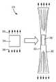
도 1 및 도 2는 광학 필름을 도시하는 도면.1 and 2 show an optical film.
도 3은 혼합 광학 필름(blended optical film)을 도시하는 도면.3 illustrates a blended optical film.
도 4는 본 발명에 따른 광학 필름을 제조하기 위한 장치 및 공정의 개략도.4 is a schematic representation of an apparatus and process for producing an optical film according to the present invention.
도 5는 본 발명의 일 실시 형태에 따른 신장 공정의 개략도.5 is a schematic diagram of an stretching process according to an embodiment of the present invention.
도 6은 배치(batch) 신장 공정 단계의 개략도.6 is a schematic of a batch stretching process step.
도 7A는 길이 배향기(length orienter)를 사용하는 필름 라인의 일 실시 형태의 개략도.7A is a schematic representation of one embodiment of a film line using a length orienter.
도 7B는 길이 배향기 스레딩 시스템(length orienter threading system)의 일 실시 형태의 개략도.7B is a schematic diagram of one embodiment of a length orienter threading system.
도 7C는 길이 배향기 스레딩 시스템의 다른 실시 형태의 개략도.7C is a schematic diagram of another embodiment of a length aligner threading system.
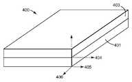
도 8은 제1 광학 필름이 제2 광학 필름에 부착된 적층 구조체를 도시하는 도면.8 shows a laminated structure with a first optical film attached to a second optical film.
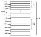
도 9A 및 도 9B는 본 발명에 따라 제조된 예시적인 구조체의 단면도.9A and 9B are cross-sectional views of exemplary structures made in accordance with the present invention.
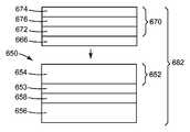
도 10A 내지 도 10C는 본 발명에 따라 제조된 예시적인 구조체의 단면도.10A-10C are cross-sectional views of exemplary structures made in accordance with the present invention.
도 11은 본 발명에 따라 제조된 예시적인 구조체의 단면도.11 is a cross-sectional view of an exemplary structure made in accordance with the present invention.
본 발명은 광학 필름, 예컨대 디스플레이의 휘도를 향상시킬 수 있는 광학 필름의 제조에 관한 것이다. 광학 필름은, 예를 들어 이러한 필름이 광학 디스플레이와 같은 특정한 최종 용도의 응용을 위해 설계된 광학적 균일성 및 충분한 광학적 품질을 필요로 한다는 점에서 다른 필름들과 상이하다. 본 출원의 목적에 대해, 광학 디스플레이에 사용하기에 충분한 품질은 모든 처리 단계 후의 그리고 다른 필름에의 적층 전의 롤 형태인 광학 필름에 현저한 가시적인 결함이 없는 것, 예를 들어 육안으로 관찰할 때 색줄(color streak) 또는 표면 리지(surface ridge)가 실질적으로 없는 것을 의미한다. 또한, 광학 품질 필름은 특정 응용에 대해 충분히 작은, 예컨대 필름의 평균 두께의 +/- 10%, +/- 5% 이하, +/- 3% 이하, 그리고 몇몇 경우에서는 +/- 1% 이하의 유용한 필름 영역에 걸친 캘리퍼(caliper) 변동을 가져야 한다. 본 발명에 따른 광학 필름의 바람직하지 않은 외관 또는 특성을 회피하기 위해, 캘리퍼 변동의 공간적 구배(spatial gradient) 역시 충분히 작아야 한다. 예를 들어, 동일한 양의 캘리퍼 변동이라도 더 큰 영역에 걸쳐 발생하는 경우 바람직하지 못한 정도가 덜 할 것이다.The present invention relates to the production of an optical film, such as an optical film capable of improving the brightness of a display. Optical films differ from other films in that such films require optical uniformity and sufficient optical quality designed for specific end use applications such as optical displays. For the purposes of the present application, a quality sufficient for use in an optical display is such that there is no significant visible defect in the optical film in the form of a roll after all processing steps and before lamination to other films, e.g. when viewed with the naked eye it means substantially no color streak or surface ridge. In addition, optical quality films are sufficiently small for a particular application, such as +/- 10%, +/- 5% or less, +/- 3% or less, and in some cases up to +/- 1% of the average thickness of the film. It should have caliper variation over the useful film area. In order to avoid the undesirable appearance or properties of the optical film according to the invention, the spatial gradient of caliper fluctuations must also be sufficiently small. For example, even the same amount of caliper variation will be less undesirable if it occurs over a larger area.
그 길이를 따라(MD를 따라) 차단 또는 편광축을 갖는 반사 편광 필름과 같은 넓은 배향된 광학 필름을 제조하기 위한 방법, 및 이러한 방법에 의해 제조될 수 있는 그 길이를 따라(MD를 따라) 차단 또는 편광축을 갖는 넓은 필름의 롤은, 모두 2006년 3월 31일자로 출원된, 공동 소유의 미국 특허 출원 제11/394,479호 및 제11/394,478호에 설명되어 있으며, 이들 출원의 개시 내용은 이로써 본 명세서에 참고로 포함된다. 반사 편광 필름은 다층 반사 편광 필름 및 확산 반사 편광 광학 필름을 포함할 수 있지만, 이에 제한되지 않는다. 몇몇 예시적인 실시 형태에서, 반사 편광 필름은 다른 광학 필름, 예컨대 흡수 편광기, 지연기(retarder), 확산기, 보호 필름, 표면 구조화된 필름 등에 롤-투-롤(roll-to-roll) 공정으로 적층될 수 있는 것이 유리하다.A method for producing a wide oriented optical film, such as a reflective polarizing film having a blocking or polarizing axis along its length (along the MD), and a blocking (along the MD) along its length that can be produced by such a method, or Rolls of wide films having polarization axes are described in commonly owned US patent applications Ser. Nos. 11 / 394,479 and 11 / 394,478, filed March 31, 2006, the disclosures of which are hereby incorporated by reference. It is incorporated herein by reference. The reflective polarizing film may include, but is not limited to, a multilayer reflective polarizing film and a diffuse reflective polarizing optical film. In some exemplary embodiments, the reflective polarizing film is laminated in a roll-to-roll process to other optical films such as absorbing polarizers, retarders, diffusers, protective films, surface structured films, and the like. It is advantageous to be able.
본 출원의 목적에 대해, "넓은"(wide) 또는 "넓은 형태"(wide format)라는 용어는 폭이 약 0.3 m 초과인 필름을 지칭한다. 당업자라면, "폭"이라는 용어는, 필름의 에지의 소정 부분이 예를 들어 텐터(tenter)의 파지 부재에 의해 사용할 수 없게 되거나 결함을 갖게 될 수 있기 때문에, 유용한 필름 폭에 관하여 사용될 것임을 쉽게 알 것이다. 본 발명의 넓은 광학 필름은 의도된 응용에 따라 변할 수 있는 폭을 갖지만, 전형적으로 0.3 m 초과 내지 10 m 범위의 폭을 갖는다. 몇몇 응용에서, 10 m보다 넓은 필름이 제조될 수 있지만, 이러한 필름은 운반하기에 어려울 수 있다. 예시적인 적합한 필름은 전형적으로 폭이 약 0.5 m 내지 약 2 m, 그리고 최대 약 7 m이며, 현재 이용가능한 디스플레이 필름 제품은 폭이 예컨대 0.65 m, 1.3 m, 1.6 m, 1.8 m 또는 2.0 m인 필름을 이용한다. "롤"(roll)이라는 용어는 길이가 10 m 이상인 연속 필름을 말한다. 본 발명의 몇몇 예시적인 실시 형태에서, 필름의 길이는 20 m 이상, 50 m 이상, 100 m 이상, 200 m 이상, 또는 임의의 다른 적합한 길이일 수 있다.For the purposes of the present application, the term "wide" or "wide format" refers to a film that is greater than about 0.3 m in width. Those skilled in the art will readily appreciate that the term "width" will be used with respect to useful film widths because certain portions of the edges of the film may become unusable or defective, for example by gripping members of the tenter. will be. The wide optical films of the present invention have a width that can vary depending on the intended application, but typically have a width in the range of more than 0.3 m to 10 m. In some applications, films wider than 10 m can be made, but such films can be difficult to transport. Exemplary suitable films typically range from about 0.5 m to about 2 m, and up to about 7 m, and currently available display film products are films that are, for example, 0.65 m, 1.3 m, 1.6 m, 1.8 m or 2.0 m wide. Use The term "roll" refers to a continuous film of 10 m or more in length. In some exemplary embodiments of the invention, the length of the film may be at least 20 m, at least 50 m, at least 100 m, at least 200 m, or any other suitable length.
하기의 설명은 여러 도면에서 동일한 요소들에 동일한 방식으로 번호가 부여된 도면들을 참조하여 이해되어야 한다. 반드시 축척대로 도시된 것은 아닌 도면들은 선택된 예시적인 실시 형태들을 도시하며, 본 발명의 범주를 제한하고자 하는 것이 아니다. 구성, 치수 및 재료의 예가 다양한 요소에 대하여 예시되어 있지만, 당업자라면 다수의 제공된 예들이 이용될 수 있는 적합한 대안을 가짐을 인식할 것이다.The following description should be understood with reference to the drawings, wherein like elements are numbered in the same manner in the various figures. The drawings, which are not necessarily drawn to scale, illustrate selected exemplary embodiments and are not intended to limit the scope of the invention. Although examples of configurations, dimensions, and materials are illustrated for various elements, those skilled in the art will recognize that many provided examples have suitable alternatives that may be used.
달리 지시되지 않는 한, 명세서 및 청구의 범위에서 사용되는 특징부 크기, 양 및 물리적 특성을 표현하는 모든 수치는 모든 경우 "약"이라는 용어에 의해 수식되는 것으로 이해되어야 한다. 따라서, 반대로 지시되지 않는 한, 전술한 명세서 및 첨부된 청구의 범위에 기술된 수치적 파라미터는 근사치이며, 이 근사치는 본 명세서에 개시된 교시 내용을 이용하는 당업자가 얻고자 하는 원하는 특성에 따라 달라질 수 있다.Unless otherwise indicated, all numbers expressing feature sizes, quantities, and physical properties used in the specification and claims are to be understood as being modified in all instances by the term "about." Accordingly, unless indicated to the contrary, the numerical parameters set forth in the foregoing specification and the appended claims are approximations, which may vary depending upon the desired properties desired by those skilled in the art using the teachings disclosed herein. .
종점(endpoint)에 의한 수치 범위의 언급은 그 범위 내에 포함되는 모든 수(예를 들어, 1 내지 5는 1, 1.5, 2, 2.75, 3, 3.80, 4 및 5를 포함함)와 그 범위 내의 임의의 범위를 포함한다.Reference to a numerical range by endpoint refers to any number within the range (eg, 1 to 5 includes 1, 1.5, 2, 2.75, 3, 3.80, 4, and 5) and within that range. It includes any range.
본 명세서 및 첨부된 청구의 범위에서 사용되는 바와 같이, 단수 형태("a", "an" 및 "the")는 그 내용이 명백하게 다르게 지시하지 않는 한 복수의 지시 대상을 갖는 실시 형태를 포함한다. 예를 들어, "하나의 필름"(a film)을 참조하는 것은 1개, 2개 또는 그 이상의 필름을 갖는 실시 형태를 포함한다. 본 명세서 및 첨부된 청구의 범위에서 사용되는 바와 같이, "또는"이라는 용어는 일반적으로 그 내용이 명백하게 다르게 지시하지 않는 한 "및/또는"을 포함하는 의미로 이용된다.As used in this specification and the appended claims, the singular forms “a,” “an,” and “the” include embodiments having plural referents, unless the content clearly dictates otherwise. . For example, referring to "a film" includes embodiments having one, two or more films. As used in this specification and the appended claims, the term “or” is generally employed in its sense including “and / or” unless the content clearly dictates otherwise.
"복굴절성"(birefringent)이라는 용어는 직교하는 x, y 및 z 방향에서의 굴절률들이 모두 동일하지는 않음을 의미한다. 본 명세서에서 설명되는 중합체 층의 경우, 축들은, x 및 y 축이 층의 평면 내에 있고 z 축이 층의 두께 또는 높이에 대응하도록 선택된다. 주축은 굴절률이 최대 및 최소값인 방향을 지칭한다. "평면내 복굴절"(in-plane birefringence)이라는 용어는 주 평면내 굴절률들(nx 및 ny) 간의 차이인 것으로 이해되어야 한다. "평면외 복굴절"(out-of-plane birefringence)이라는 용어는 주 평면내 굴절률들 중 하나(nx 또는 ny)와 주 평면외 굴절률(nz) 간의 차이인 것으로 이해되어야 한다. 주 평면내 방향들은 전형적으로, 특히 웨브를 교차하여 대칭인 공정의 필름 중앙에서 대체로 웨브 횡단/횡방향(TD) 및 웨브 하류/기계 방향(MD)으로 정렬된다. 주 평면외 방향은 수직 방향(ND)과 거의 같을 수 있다. 모든 복굴절 및 굴절률 값은 달리 지시되지 않는 한 632.8 ㎚ 광에 대해 보고된다.The term "birefringent" means that the refractive indices in the orthogonal x, y and z directions are not all the same. In the case of the polymer layer described herein, the axes are selected such that the x and y axes are in the plane of the layer and the z axis corresponds to the thickness or height of the layer. The major axis refers to the direction in which the refractive index is the maximum and minimum value. The term "in-plane birefringence" should be understood to be the difference between the major in-plane birefringence indexes nx and ny . The term "out-of-plane birefringence" should be understood to be the difference between one of the major in-plane refractive indices (nx or ny ) and the out-of-plane birefringence nz . The principal in-plane directions are typically aligned in a generally web transverse / transverse (TD) and web downstream / machine direction (MD), in particular in the film center of the process which is symmetrical across the web. The main out-of-plane direction may be approximately equal to the vertical direction ND. All birefringence and refractive index values are reported for 632.8 nm light unless otherwise indicated.
복굴절성의 배향된 층은 전형적으로 배향된 방향(즉, 신장 방향)과 평행한 편광면을 가진 입사 광선과 횡방향(즉, 신장 방향에 직교하는 방향)과 평행한 편광면을 가진 광선의 투과 및/또는 반사 간의 차이를 나타낸다. 예컨대, 배향가능한 폴리에스테르 필름이 x 축을 따라 신장될 때, 전형적인 결과는 nx ≠ ny이며, 여기서 nx 및 ny는 각각 "x" 및 "y" 축에 평행한 평면 내에서 편광된 광의 굴절률이다. 신장 방향을 따른 굴절률의 변경 정도는 신장량, 신장률, 신장 동안의 필름 온도, 필름 두께, 필름 두께의 변동, 및 필름의 조성과 같은 인자에 좌우될 것이다.A birefringent oriented layer typically transmits incident light rays with a polarization plane parallel to the oriented direction (ie, the stretching direction) and transmission of light rays with a polarization plane parallel to the transverse direction (ie, the direction perpendicular to the stretching direction) and And / or the difference between reflections. For example, when an oriented polyester film is stretched along the x axis, a typical result is nx ≠ ny where nx and ny are the polarizations of light polarized in a plane parallel to the "x" and "y" axes, respectively. Refractive index. The degree of change in the refractive index along the stretching direction will depend on factors such as the amount of elongation, elongation rate, film temperature during elongation, film thickness, variation in film thickness, and composition of the film.
재료의 굴절률은 파장의 함수인 것(즉, 재료는 전형적으로 분산을 나타냄)이 이해될 것이다. 따라서, 굴절률에 대한 광학 요건이 또한 파장의 함수이다. 2개의 광학적으로 연결된 재료의 굴절률 비는 2개 재료의 반사능(reflective power)을 계산하는 데에 사용될 수 있다. 특정 방향을 따라 편광된 광에 대한 2개의 재료들 사이의 굴절률 차이를 동일한 방향을 따라 편광된 광에 대한 이들 재료의 평균 굴절률로 나눈 절대값이 필름의 광학 성능을 설명한다. 이는 정규화된 굴절률 차이라 부를 것이다.It will be understood that the refractive index of the material is a function of the wavelength (ie, the material typically exhibits dispersion). Thus, optical requirements for refractive index are also a function of wavelength. The refractive index ratio of two optically connected materials can be used to calculate the reflective power of the two materials. The absolute value of the refractive index difference between the two materials for light polarized along a particular direction divided by the average refractive index of these materials for light polarized along the same direction accounts for the optical performance of the film. This will be called the normalized refractive index difference.
반사 편광기에서, 예를 들어 평면내(MD) 방향에서와 같은 부정합된(mismatched) 평면내 굴절률들의 정규화된 차이는, 만일 존재한다면, 약 0.06 이상, 더 바람직하게는 약 0.09 이상, 더욱 더 바람직하게는 약 0.11 이상 또는 그보다 큰 것이 일반적으로 바람직하다. 더욱 일반적으로, 이러한 차이는 광학 필름의 다른 양태를 현저하게 저하시키지 않고서 가능한 한 큰 것이 바람직하다. 또한, 예를 들어 평면내(TD) 방향에서와 같은 정합된(matched) 평면내 굴절률들의 정규화된 차이는, 만일 존재한다면, 약 0.06 미만, 더 바람직하게는 약 0.03 미만, 가장 바람직하게는 약 0.01 미만인 것이 일반적으로 바람직하다. 유사하게, 예를 들어 평면외(ND) 방향에서와 같이 편광 필름의 두께 방향의 굴절률들의 임의의 정규화된 차이는 약 0.11 미만, 약 0.09 미만, 약 0.06 미만, 더 바람직하게는 약 0.03 미만, 가장 바람직하게는 약 0.01 미만인 것이 바람직할 수 있다.In reflective polarizers, the normalized difference of mismatched in-plane refractive indices, such as in the in-plane (MD) direction, if present, is at least about 0.06, more preferably at least about 0.09, even more preferably Is preferably at least about 0.11 or greater. More generally, this difference is preferably as large as possible without significantly lowering other aspects of the optical film. In addition, the normalized difference of matched in-plane refractive indices, such as in the in-plane (TD) direction, if present, is less than about 0.06, more preferably less than about 0.03, most preferably about 0.01 It is generally preferred that it is less than. Similarly, any normalized difference in refractive indices in the thickness direction of the polarizing film, for example in the out-of-plane (ND) direction, is less than about 0.11, less than about 0.09, less than about 0.06, more preferably less than about 0.03, most It may be desirable to be less than about 0.01.
소정의 경우에, 다층 적층체 내의 2개의 인접한 재료의 두께 방향으로의 제어된 부정합을 갖는 것이 바람직할 수도 있다. 이러한 필름의 광학 성능에 대한 다층 필름 내의 2개의 재료의 z-축 굴절률의 영향은 발명의 명칭이 "광학 필름"(Optical Film)인 미국 특허 제5,882,774호; 발명의 명칭이 "변색 필름"(Color Shifting Film)인 미국 특허 제6,531,230호; 및 발명의 명칭이 "날카로운 밴드에지를 갖는 광학 필름"(Optical Film with Sharpened Bandedge)인 미국 특허 제6,157,490호에 더 상세히 설명되어 있고, 이들 특허의 내용은 본 명세서에 참고로 포함된다. 몇몇 예시적인 광학 필름에서, 비-신장 방향을 따라 편광된 광에 대한 굴절률(nx)과 두께 방향을 따라 편광된 광에 대한 굴절률(nz) 사이의 정규화된 차이는, 만일 존재한다면, 예컨대 약 0.06 미만, 더 바람직하게는 약 0.03 미만, 가장 바람직하게는 약 0.01 미만만큼 가능한 한 작은 것이 일반적으로 바람직하다.In certain cases, it may be desirable to have controlled mismatches in the thickness direction of two adjacent materials in a multilayer stack. The influence of the z-axis refractive index of the two materials in the multilayer film on the optical performance of such films is described in US Pat. No. 5,882,774, entitled "Optical Film"; US Patent No. 6,531,230, entitled "Color Shifting Film"; And US Pat. No. 6,157,490, entitled "Optical Film with Sharpened Bandedge," the contents of which are incorporated herein by reference. In some exemplary optical films, the normalized difference between the refractive index nx for light polarized along the non-elongation direction and the refractive index nz for light polarized along the thickness direction, if present, for example It is generally preferred to be as small as possible by less than about 0.06, more preferably less than about 0.03, most preferably less than about 0.01.
본 발명의 예시적인 실시 형태는 굴절률이 변형-유도 배향(strain-induced orientation)의 결과로서 가장 많이 변경된 평면내 방향인 "유효 배향축"을 특징으로 할 수 있다. 예를 들어, 유효 배향축은 전형적으로 반사 또는 흡수 편광 필름의 차단축과 일치한다. 일반적으로, 최대 및 최소 굴절률 값에 대응하는 평면내 굴절률들에 대한 2개의 주축이 있다. 주요 축 또는 신장 방향을 따라 편광된 광에 대해 굴절률이 증가하는 경향을 갖는 양의 복굴절성 재료의 경우, 유효 배향축은 최대 평면내 굴절률의 축과 일치한다. 주요 축 또는 신장 방향을 따라 편광된 광에 대해 굴절률이 감소하는 경향을 갖는 음의 복굴절성 재료의 경우, 유효 배향축은 최소 평면내 굴절률의 축과 일치한다.Exemplary embodiments of the present invention can be characterized by an "effective orientation axis" where the refractive index is the most altered in-plane direction as a result of strain-induced orientation. For example, the effective orientation axis typically coincides with the blocking axis of the reflective or absorbing polarizing film. In general, there are two major axes for in-plane refractive indices corresponding to the maximum and minimum refractive index values. For positive birefringent materials that have a tendency to increase in refractive index for light polarized along the major axis or extension direction, the effective orientation axis coincides with the axis of maximum in-plane refractive index. For negative birefringent materials that have a tendency to decrease in refractive index for light polarized along the major axis or extension direction, the effective orientation axis coincides with the axis of the minimum in-plane refractive index.
도 1은 이하 설명되는 공정에 사용될 수 있는 광학 필름 구조체(101)의 일부를 도시한다. 도시된 광학 필름(101)은 3개의 상호 직교하는 축 x, y 및 z를 참조하여 설명될 수 있다. 도시된 실시 형태에서, 2개의 직교하는 축 x 및 y는 필름(101)의 평면 내에 있으며, 제3 축(z-축)은 필름 두께 방향으로 연장한다. 몇몇 예시적인 실시 형태에서, 광학 필름(101)은 광학적으로 연결된 적어도 2개의 상이한 재료, 즉 제1 재료 및 제2 재료(예를 들어, 반사, 산란, 투과 등과 같은 광학 효과를 야기하도록 조합되는 2개의 재료)를 포함한다. 본 발명의 전형적인 실시 형태에서, 하나 또는 두 재료 모두는 중합체이다.1 shows a portion of an
제1 및 제2 재료는 필름(101)의 적어도 하나의 축을 따른, 예컨대 x 방향을 따른 방향에서의 굴절률들의 원하는 부정합을 생성하도록 선택될 수 있다. 바람직하게는, y 방향을 따른 굴절률들의 부정합은 0.05 이상, 0.07 이상, 0.1 이상, 더 바람직하게는 0.2 이상이다. 재료들은 또한 굴절률들이 부정합된 방향에 수직인 필름(101)의 적어도 하나의 다른 축을 따른, 예컨대 y 방향을 따른 방향에서의 굴절률들의 원하는 정합을 생성하도록 선택될 수 있다. 바람직하게는, x 방향을 따른 굴절률들 사이의 차이는 0.05 미만, 0.04 이하, 0.03 이하, 더 바람직하게는 0.02 이하이다. 몇몇 예시적인 실시 형태에서, 재료들은 또한 굴절률들이 부정합된 방향에 수직인 필름(101)의 2개의 축을 따른, 예컨대 y 및 x 두 방향 모두를 따른 방향에서의 굴절률들의 원하는 정합을 생성하도록 선택될 수 있다. 그러한 예시적인 실시 형태에서, x 및 y 방향을 따른 제1 및 제2 재료의 굴절률들 사이의 차이는 모두 0.05 미만, 0.04 이하, 0.03 이하, 더 바람직하게는 0.02 이하이다.The first and second materials may be selected to produce a desired mismatch of refractive indices along at least one axis of the
제1 및 제2 재료 중 적어도 하나의 재료는 소정 조건 하에서 음 또는 양의 복굴절을 발생시키기 쉬울 수 있다. 광학 필름에 사용되는 재료들은 공압출 공정의 요건을 충족시키기에 충분히 유사한 리올로지(rheology)를 갖도록 선택되는 것이 바람직하지만, 주조 필름이 또한 사용될 수 있다. 다른 예시적인 실시 형태에서, 광학 필름(101)은 단지 하나의 재료, 또는 2개 이상의 재료들의 혼화성 블렌드로 구성될 수 있다. 이러한 예시적인 실시 형태는 광학 디스플레이에서 지연기 또는 보상기로서 사용될 수 있다.At least one of the first and second materials may be susceptible to generating negative or positive birefringence under certain conditions. The materials used in the optical film are preferably selected to have a rheology sufficiently similar to meet the requirements of the coextrusion process, but cast films may also be used. In another exemplary embodiment, the
몇몇 예시적인 실시 형태에서, 본 발명의 광학 필름은 복굴절성 재료, 때로는 단지 하나의 복굴절성 재료를 포함한다. 다른 예시적인 실시 형태에서, 본 발명의 광학 필름은 적어도 하나의 복굴절성 재료 및 적어도 하나의 등방성 재료를 포함한다. 또 다른 예시적인 실시 형태에서, 광학 필름은 제1 복굴절성 재료 및 제2 복굴절성 재료를 포함한다. 이러한 몇몇 예시적인 실시 형태에서, 두 재료의 평면내 굴절률은 동일한 공정 조건에 응답하여 유사하게 변경된다. 일 실시 형태에서, 필름이 연신될 때, 제1 및 제2 재료의 굴절률은 모두 연신 방향(예컨대, MD)을 따라 편광된 광에 대해서는 증가하지만 신장 방향에 직교하는 방향(예컨대, TD)을 따라 편광된 광에 대해서는 감소할 것이다. 다른 실시 형태에서, 필름이 연신될 때, 제1 및 제2 재료의 굴절률은 모두 연신 방향(예컨대, MD)을 따라 편광된 광에 대해서는 감소하지만 신장 방향에 직교하는 방향(예컨대, TD)을 따라 편광된 광에 대해서는 증가할 것이다. 일반적으로, 1개, 2개 또는 그 이상의 복굴절성 재료가 본 발명에 따른 배향된 광학 필름에 사용되는 경우, 각각의 복굴절성 재료의 유효 배향축은 MD를 따라 정렬된다.In some exemplary embodiments, the optical film of the present invention comprises a birefringent material, sometimes only one birefringent material. In another exemplary embodiment, the optical film of the present invention comprises at least one birefringent material and at least one isotropic material. In yet another exemplary embodiment, the optical film includes a first birefringent material and a second birefringent material. In some of these exemplary embodiments, the in-plane refractive indices of the two materials change similarly in response to the same process conditions. In one embodiment, when the film is stretched, the refractive indices of the first and second materials both increase for light polarized along the stretching direction (eg, MD) but along a direction (eg, TD) orthogonal to the stretching direction. It will decrease for polarized light. In another embodiment, when the film is stretched, the refractive indices of the first and second materials both decrease for light polarized along the stretching direction (eg, MD) but along a direction (eg, TD) orthogonal to the stretching direction. It will increase for polarized light. In general, when one, two or more birefringent materials are used in the oriented optical film according to the invention, the effective orientation axis of each birefringent material is aligned along the MD.
연신 단계 또는 연신 단계들의 조합에 기인한 배향에 의해 하나의 평면내 방향에서의 2개의 재료의 굴절률들의 정합 및 다른 하나의 평면내 방향에서의 굴절률들의 실질적인 부정합이 형성된 때, 필름은 반사 편광기의 제조에 특히 적합하게 된다. 정합된 방향은 편광기에 대한 투과(통과) 방향을 형성하고, 부정합된 방향은 반사(차단) 방향을 형성한다. 일반적으로, 반사 방향에서의 굴절률들의 부정합이 커지고 투과 방향에서의 정합이 근접할수록, 편광기의 성능이 우수해진다.When the orientation due to the stretching step or the combination of the stretching steps forms a match of the refractive indices of the two materials in one in-plane direction and a substantial mismatch of the refractive indices in the other in-plane direction, the film produces a reflective polarizer. It is particularly suitable for. The matched direction forms the transmission (pass) direction for the polarizer and the mismatched direction forms the reflection (blocking) direction. In general, the greater the mismatch of the refractive indices in the reflection direction and the closer the match in the transmission direction, the better the performance of the polarizer.
한편, 복굴절성 재료 또는 재료들이 비-신장 방향을 따른, 예컨대 y 및 z 방향을 따른 굴절률들 사이의 차이를 나타내는 경우, 편광기 응용에 사용되는 몇몇 광학 필름은 오프-축 컬러(off-axis color)를 겪는다. 따라서, 본 발명의 예시적인 실시 형태에 포함되는 복굴절성 재료들은 비-신장 방향을 따른 굴절률들 사이의 부정합이 가능한 한 작아야 한다. 비-신장 방향(즉, y-방향 및 z-방향)에서의 굴절률들은 주어진 복굴절성 층 또는 영역에 대해 서로의 약 5% 이내, 하나 초과의 재료를 포함하는 실시 형태에서는 상이한 재료의 인접한 층 또는 영역의 대응하는 비-신장 방향들의 약 5% 이내인 것이 바람직하다.On the other hand, if the birefringent material or materials exhibit a difference between the refractive indices along the non-elongation direction, such as along the y and z directions, some optical films used in polarizer applications may have off-axis color. Suffers. Therefore, the birefringent materials included in the exemplary embodiment of the present invention should have as little mismatch as possible between the refractive indices along the non-elongation direction. The refractive indices in the non-extending direction (ie, the y- and z-directions) are within about 5% of each other for a given birefringent layer or region, in embodiments comprising more than one material, in adjacent layers of different materials or It is preferred to be within about 5% of the corresponding non-extending directions of the region.
도 2는 제2 재료(115)의 제2 층 상에 (예컨대, 공압출에 의해) 배치된 제1 재료(113)의 제1 층을 포함하는 다층 광학 필름(111)을 도시한다. 제1 및 제2 재료 중 어느 하나 또는 둘 모두가 복굴절성일 수 있다. 단지 2개의 층이 도 2에 도시되어 있고 본 명세서에서 일반적으로 설명되지만, 공정은 예를 들어 제1 재료(113)의 복수의 제1 층 및 제2 재료(115)의 복수의 제2 층과 같이 임의의 수의 상이한 재료로부터 제조되는 최대 수백 또는 수천 또는 그 이상의 층을 갖는 다층 광학 필름에 적용될 수 있다. 다층 광학 필름(111) 또는 광학 필름(101)은 추가의 층을 포함할 수 있다. 추가의 층은, 예컨대 추가의 광학적 기능을 수행하는 광학 층, 또는 예컨대 그 기계적 또는 화학적 특성을 위해 선택되는 비-광학 층, 또는 둘 모두일 수 있다. 본 명세서에 참고로 포함된 미국 특허 제6,179,948호에 논의된 바와 같이, 이들 추가의 층은 본 명세서에 설명된 공정 조건 하에서 배향가능할 수 있으며, 필름의 전체 광학적 및/또는 기계적 특성에 기여할 수 있지만, 명확함 및 단순함의 목적으로 이들 층은 본 명세서에서 추가로 논의되지 않을 것이다.FIG. 2 shows a multilayer
광학 필름(111)의 재료들은 필름(111)의 2개의 재료(113, 115)의 연신 거동을 적어도 부분적으로 분리시키기 위해 점탄성 특징을 갖도록 선택된다. 예를 들어, 몇몇 예시적인 실시 형태에서, 신장 또는 연신에 대한 2개의 재료(113, 115)의 응답을 분리시키는 것이 유리하다. 연신 거동을 분리시킴으로써, 재료들의 굴절률 변경이 배향 상태들의 다양한 조합 및 그에 따른 2개의 상이한 재료에서의 복굴절의 정도를 달성하도록 별도로 제어될 수 있다. 이러한 하나의 공정에서, 2개의 상이한 재료는 공압출된 다층 광학 필름과 같은 다층 광학 필름의 광학 층들을 형성한다. 이러한 층들의 굴절률은 초기 등방성을 가질 수 있지만(즉, 굴절률은 각각의 축을 따라 동일함), 주조 공정 동안 소정의 배향이 의도적으로 또는 우발적으로 압출 필름에 도입될 수도 있다.The materials of the
반사 편광기를 형성하는 하나의 접근법은 본 발명에 따른 처리의 결과로서 복굴절성이 되는 제1 재료, 및 연신 공정 동안 실질적으로 등방성으로 유지되는, 즉 감지할 수 있을 정도의 복굴절을 발생시키지 않는 굴절률을 갖는 제2 재료를 사용한다. 몇몇 예시적인 실시 형태에서, 제2 재료는 연신 후에 제1 재료의 비-연신 평면내 굴절률에 정합하는 굴절률을 갖도록 선택된다.One approach to forming reflective polarizers includes a first material that becomes birefringent as a result of the treatment according to the present invention, and a refractive index that remains substantially isotropic during the stretching process, i.e., does not produce a detectable birefringence. The second material which has is used. In some exemplary embodiments, the second material is selected to have a refractive index that matches the non-stretch in-plane refractive index of the first material after stretching.
도 1 및 도 2의 광학 필름에 사용하기에 적합한 재료는, 예를 들어 본 명세서에 참고로 포함된 미국 특허 제5,882,774호에 논의되어 있다. 적합한 재료는 중합체, 예컨대 폴리에스테르, 코폴리에스테르 및 개질된 코폴리에스테르를 포함한다. 이와 관련하여, "중합체"라는 용어는, 예를 들어 공압출에 의해 또는 예컨대 에스테르 교환(transesterification)을 포함하는 반응에 의해 혼화성 블렌드로 형성될 수 있는 중합체 또는 공중합체뿐만 아니라 단일중합체와 공중합체도 포함한다는 것을 이해할 것이다. "중합체" 및 "공중합체"라는 용어는 랜덤 및 블록 공중합체 모두를 포함한다. 본 발명에 따라 구성되는 광학체의 몇몇 예시적인 광학 필름에 사용하기에 적합한 폴리에스테르는 일반적으로 카르복실레이트 및 글리콜 서브유닛을 포함하며, 카르복실레이트 단량체 분자와 글리콜 단량체 분자의 반응에 의해 생성될 수 있다. 각각의 카르복실레이트 단량체 분자는 2개 이상의 카르복실산 또는 에스테르 작용기를 가지며, 각각의 글리콜 단량체 분자는 2개 이상의 하이드록시 작용기를 가진다. 카르복실레이트 단량체 분자는 모두 동일할 수도 있거나, 2개 이상의 상이한 유형의 분자가 존재할 수도 있다. 이는 동일하게 글리콜 단량체 분자에 적용된다. "폴리에스테르"라는 용어 내에 또한 포함되는 것은 글리콜 단량체 분자와, 탄산의 에스테르의 반응으로부터 유도되는 폴리카르보네이트이다.Materials suitable for use in the optical films of FIGS. 1 and 2 are discussed, for example, in US Pat. No. 5,882,774, which is incorporated herein by reference. Suitable materials include polymers such as polyesters, copolyesters and modified copolyesters. In this regard, the term “polymer” refers to homopolymers and copolymers as well as to polymers or copolymers which may be formed into miscible blends, for example by coextrusion or by reactions including transesterification, for example. It will also be understood to include. The terms "polymer" and "copolymer" include both random and block copolymers. Polyesters suitable for use in some exemplary optical films of the optics constructed in accordance with the present invention generally comprise carboxylates and glycol subunits, which may be produced by reaction of carboxylate monomer molecules with glycol monomer molecules. Can be. Each carboxylate monomer molecule has two or more carboxylic acid or ester functional groups, and each glycol monomer molecule has two or more hydroxy functional groups. The carboxylate monomer molecules may all be the same, or two or more different types of molecules may be present. This applies equally to glycol monomer molecules. Also included within the term "polyester" are polycarbonates derived from the reaction of glycol monomer molecules with esters of carbonic acid.
폴리에스테르 층의 카르복실레이트 서브유닛의 형성에 사용하기에 적합한 카르복실레이트 단량체 분자는, 예를 들어 2,6-나프탈렌 다이카르복실산 및 그 이성체; 테레프탈산; 아이소프탈산; 프탈산; 아젤라산; 아디프산; 세바식산; 노르보르넨 다이카르복실산; 바이-사이클로옥탄 다이카르복실산; 1,6-사이클로헥산 다이카르복실산 및 그 이성체; t-부틸 아이소프탈산, 트라이멜리트산, 소듐 설포네이티드 아이소프탈산(sodium sulfonated isophthalic acid); 2,2'-바이페닐 다이카르복실산 및 그 이성체; 및 이들 산의 저급 알킬 에스테르, 예를 들어 메틸 또는 에틸 에스테르를 포함한다. 이와 관련하여, "저급 알킬"이라는 용어는 C1-C10 직쇄 또는 분지형 알킬기를 지칭한다.Suitable carboxylate monomer molecules for use in forming the carboxylate subunits of the polyester layer include, for example, 2,6-naphthalene dicarboxylic acid and isomers thereof; Terephthalic acid; Isophthalic acid; Phthalic acid; Azelaic acid; Adipic acid; Sebacic acid; Norbornene dicarboxylic acid; Bi-cyclooctane dicarboxylic acid; 1,6-cyclohexane dicarboxylic acid and isomers thereof; t-butyl isophthalic acid, trimellitic acid, sodium sulfonated isophthalic acid; 2,2'-biphenyl dicarboxylic acid and isomers thereof; And lower alkyl esters of these acids, such as methyl or ethyl esters. In this regard, the term "lower alkyl" refers to a C1-C10 straight or branched alkyl group.
폴리에스테르 층의 글리콜 서브유닛의 형성에 사용하기에 적합한 글리콜 단량체 분자는 에틸렌 글리콜; 프로필렌 글리콜; 1,4-부탄다이올 및 그 이성체; 1,6-헥산다이올; 네오펜틸 글리콜; 폴리에틸렌 글리콜; 다이에틸렌 글리콜; 트라이사이클로데칸다이올; 1,4-사이클로헥산다이메탄올 및 그 이성체; 노르보르난다이올; 바이사이클로-옥탄다이올; 트라이메틸올 프로판; 펜타에리트리톨; 1,4-벤젠다이메탄올 및 그 이성체; 비스페놀 A; 1,8-다이하이드록시 바이페닐 및 그 이성체; 및 1,3-비스(2-하이드록시에톡시)벤젠을 포함한다.Suitable glycol monomer molecules for use in forming the glycol subunits of the polyester layer include ethylene glycol; Propylene glycol; 1,4-butanediol and its isomers; 1,6-hexanediol; Neopentyl glycol; Polyethylene glycol; Diethylene glycol; Tricyclodecanediol; 1,4-cyclohexanedimethanol and isomers thereof; Norbornanediol; Bicyclo-octanediol; Trimethylol propane; Pentaerythritol; 1,4-benzenedimethanol and its isomers; Bisphenol A; 1,8-dihydroxy biphenyl and isomers thereof; And 1,3-bis (2-hydroxyethoxy) benzene.
본 발명의 광학 필름에 유용한 예시적인 중합체는, 예컨대 나프탈렌 다이카르복실산과 에틸렌 글리콜의 반응에 의해 제조될 수 있는 폴리에틸렌 나프탈레이트(PEN)이다. 폴리에틸렌 2,6-나프탈레이트(PEN)는 흔히 제1 중합체로서 선택된다. PEN은 큰 양의 응력 광학 계수(positive stress optical coefficient)를 가지며, 신장 후 복굴절을 효과적으로 유지하고, 가시광 범위 내에서 흡광도(absorbance)를 거의 또는 전혀 갖지 않는다. PEN은 또한 등방성 상태에서 큰 굴절률을 갖는다. 550 ㎚ 파장의 편광된 입사광에 대한 그의 굴절률은 편광면이 신장 방향에 평행할 때 약 1.64로부터 약 1.9만큼 높게 증가한다. 분자 배향의 증대는 PEN의 복굴절을 증가시킨다. 분자 배향은 재료를 더 높은 신장비로 신장시키고 다른 신장 조건을 고정시켜 유지함으로써 증대될 수 있다. 제1 중합체로서 적합한 다른 반결정질 폴리에스테르는, 예를 들어 폴리부틸렌 2,6-나프탈레이트(PBN), 폴리에틸렌 테레프탈레이트(PET), 및 그 공중합체를 포함한다.Exemplary polymers useful in the optical films of the present invention are polyethylene naphthalates (PEN), which may be prepared, for example, by reaction of naphthalene dicarboxylic acid with ethylene glycol.
몇몇 예시적인 실시 형태에서, 제2 광학 층의 제2 중합체는 완성된 필름에서, 적어도 하나의 방향의 굴절률이 그 방향과 동일한 방향의 제1 중합체의 굴절률과 현저히 다르도록 선택되어야 한다. 중합체 재료는 전형적으로 분산성이기 때문에, 즉 그들의 굴절률이 파장에 따라 변하기 때문에, 이들 조건이 특정한 관심 스펙트럼 대역폭과 관련하여 고려되어야 한다. 전술한 논의로부터, 제2 중합체의 선택은 당해 다층 광학 필름의 의도된 응용뿐만 아니라, 제1 중합체에 대해 이루어진 선택 및 처리 조건에도 좌우된다는 것을 이해할 것이다.In some exemplary embodiments, the second polymer of the second optical layer should be selected such that in the finished film, the refractive index of at least one direction is significantly different from that of the first polymer in the same direction as that direction. Because polymeric materials are typically dispersible, that is, their refractive indices vary with wavelength, these conditions must be considered in relation to the particular spectral bandwidth of interest. From the foregoing discussion, it will be understood that the choice of the second polymer depends not only on the intended application of the multilayer optical film, but also on the selection and processing conditions made for the first polymer.
광학 필름에, 특히 제1 광학 층의 제1 중합체로서 사용하기에 적합한 다른 재료는, 예를 들어 본 명세서에 참고로 포함된 미국 특허 제6,352,762호 및 제6,498,683호와, 미국 특허 출원 제09/229724호, 제09/232332호, 제09/399531호 및 제09/444756호에 설명되어 있다. 제1 중합체로서 유용한 다른 폴리에스테르는 90 몰% 다이메틸 나프탈렌 다이카르복실레이트 및 10 몰% 다이메틸 테레프탈레이트로부터 유도된 카르복실레이트 서브유닛과 100 몰% 에틸렌 글리콜 서브유닛으로부터 유도된 글리콜 서브유닛을 가지며 고유 점도(intrinsic viscosity, IV)가 0.48 ㎗/g인 coPEN이다. 이 중합체의 굴절률은 대략 1.63이다. 중합체는 본 명세서에서 저융점(low melt) PEN (90/10)으로 지칭된다. 다른 유용한 제1 중합체는 이스트만 케미칼 컴퍼니(Eastman Chemical Company)(미국 테네시주 킹스포트)로부터 입수가능한, 고유 점도가 0.74 ㎗/g인 PET이다. 비-폴리에스테르 중합체가 또한 편광기 필름의 생성에 유용하다. 예를 들어, 폴리에테르 이미드가 폴리에스테르, 예컨대 PEN 및 coPEN과 함께 사용되어 다층 반사 거울을 형성할 수 있다. 다른 폴리에스테르/비-폴리에스테르 조합, 예컨대 폴리에틸렌 테레프탈레이트 및 폴리에틸렌(예를 들어, 미국 미시간주 미들랜드 소재의 다우 케미칼 코포레이션(Dow Chemical Corp.)으로부터 인게이지(Engage) 8200이라는 상표명으로 입수가능한 것)이 사용될 수 있다.Other materials suitable for use in optical films, in particular as first polymers of the first optical layer, are described, for example, in US Pat. Nos. 6,352,762 and 6,498,683 and US Patent Application No. 09/229724, which are incorporated herein by reference. Nos. 09/232332, 09/399531 and 09/444756. Other polyesters useful as the first polymer include carboxylate subunits derived from 90 mol% dimethyl naphthalene dicarboxylate and 10 mol% dimethyl terephthalate and glycol subunits derived from 100 mol% ethylene glycol subunits. CoPEN with an intrinsic viscosity (IV) of 0.48 ㎗ / g. The refractive index of this polymer is approximately 1.63. The polymer is referred to herein as low melt PEN (90/10). Another useful first polymer is PET with an intrinsic viscosity of 0.74 dl / g, available from Eastman Chemical Company (Kingsport, Tennessee, USA). Non-polyester polymers are also useful for the production of polarizer films. For example, polyether imides can be used with polyesters such as PEN and coPEN to form multilayer reflective mirrors. Other polyester / non-polyester combinations, such as polyethylene terephthalate and polyethylene (eg, available under the trade name Engage 8200 from Dow Chemical Corp., Midland, Mich.) This can be used.
제2 광학 층은 제1 중합체의 유리 전이 온도와 양립가능한 유리 전이 온도를 가지며 제1 중합체의 등방성 굴절률과 유사한 굴절률을 갖는 다양한 중합체로부터 제조될 수 있다. 광학 필름에, 특히 제2 광학 층에 사용하기에 적합한 다른 중합체의 예에는, 상기 논의된 CoPEN 중합체 외에, 비닐 나프탈렌, 스티렌, 말레산 무수물, 아크릴레이트 및 메타크릴레이트와 같은 단량체로부터 제조되는 비닐 중합체 및 공중합체가 포함된다. 그러한 중합체의 예는 폴리아크릴레이트, 폴리메타크릴레이트, 예컨대 폴리(메틸 메타크릴레이트)(PMMA) 및 아이소탁틱(isotactic) 또는 신디오탁틱(syndiotactic) 폴리스티렌을 포함한다. 다른 중합체는 축합 중합체, 예컨대 폴리설폰, 폴리아미드, 폴리우레탄, 폴리아믹산, 및 폴리이미드를 포함한다. 또한, 제2 광학 층은 폴리에스테르 및 폴리카르보네이트와 같은 중합체 및 공중합체로부터 형성될 수 있다.The second optical layer can be made from various polymers having a glass transition temperature compatible with the glass transition temperature of the first polymer and having a refractive index similar to the isotropic refractive index of the first polymer. Examples of other polymers suitable for use in optical films, particularly in the second optical layer, include, in addition to the CoPEN polymers discussed above, vinyl polymers made from monomers such as vinyl naphthalene, styrene, maleic anhydride, acrylates and methacrylates. And copolymers. Examples of such polymers include polyacrylates, polymethacrylates such as poly (methyl methacrylate) (PMMA) and isotactic or syndiotactic polystyrenes. Other polymers include condensation polymers such as polysulfones, polyamides, polyurethanes, polyamic acids, and polyimides. The second optical layer can also be formed from polymers and copolymers such as polyesters and polycarbonates.
특히 제2 광학 층에 사용하기에 적합한 다른 예시적인 중합체는 폴리메틸메타크릴레이트(PMMA)의 단일중합체, 예컨대 미국 델라웨어주 윌밍턴 소재의 이네오스 아크릴릭스, 인크.(Ineos Acrylics, Inc.)로부터 CP71 및 CP80이라는 상표명으로 입수가능한 것, 또는 PMMA보다 낮은 유리 전이 온도를 갖는 폴리에틸 메타크릴레이트(PEMA)를 포함한다. 추가의 제2 중합체는 PMMA의 공중합체(coPMMA), 예컨대 75 중량% 메틸메타크릴레이트(MMA) 단량체 및 25 중량% 에틸 아크릴레이트(EA) 단량체로부터 제조된 coPMMA(이네오스 아크릴릭스, 인크.로부터 퍼스펙스(Perspex) CP63이라는 상표명으로 입수가능한 것), MMA 공단량체 유닛 및 n-부틸 메타크릴레이트(nBMA) 공단량체 유닛으로 형성된 coPMMA, 또는 PMMA 및 폴리(비닐리덴 플루오라이드)(PVDF)의 블렌드, 예컨대 미국 텍사스주 휴스턴 소재의 솔베이 폴리머즈, 인크.(Solvay Polymers, Inc.)로부터 솔레프(Solef) 1008이라는 상표명으로 입수가능한 것을 포함한다.Other exemplary polymers that are particularly suitable for use in the second optical layer are homopolymers of polymethylmethacrylate (PMMA), such as Ineos Acrylics, Inc. of Wilmington, Delaware, USA. Commercially available under the trade names CP71 and CP80, or polyethyl methacrylate (PEMA) having a lower glass transition temperature than PMMA. Further second polymers are from copolymers of PMMA (coPMMA), such as coPMMA (Ineos Acrylics, Inc.) prepared from 75 wt% methylmethacrylate (MMA) monomers and 25 wt% ethyl acrylate (EA) monomers. Available under the brand name Perspex CP63), coPMMA formed from MMA comonomer units and n-butyl methacrylate (nBMA) comonomer units, or blends of PMMA and poly (vinylidene fluoride) (PVDF) Such as those available under the tradename Solf 1008, for example, from Solvay Polymers, Inc., Houston, Texas.
특히 제2 광학 층에 사용하기에 적합한 또 다른 중합체는 폴리올레핀 공중합체, 예컨대 다우-듀폰 엘라스토머즈(Dow-Dupont Elastomers)로부터 인게이지(Engage) 8200이라는 상표명으로 입수가능한 폴리(에틸렌-코-옥텐)(PE-PO), 미국 텍사스주 댈러스 소재의 피나 오일 앤드 케미칼 컴퍼니(Fina Oil and Chemical Co.)로부터 Z9470이라는 상표명으로 입수가능한 폴리(프로필렌-코-에틸렌)(PPPE), 및 미국 유타주 솔트 레이크 시티 소재의 헌츠만 케미칼 코포레이션(Huntsman Chemical Corp.)으로부터 렉스플렉스(Rexflex) W111이라는 상표명으로 입수가능한 아탁틱(atatctic) 폴리프로필렌(aPP) 및 아이소탁틱(isotatctic) 폴리프로필렌(iPP)의 공중합체를 포함한다. 광학 필름은 또한 예를 들어 제2 광학 층에 작용화된 폴리올레핀, 예컨대 미국 델라웨어주 윌밍턴 소재의 이.아이. 듀폰 디 네모아 앤드 컴퍼니, 인크.(E.I. duPont de Nemours & Co., Inc.)로부터 바이넬(Bynel) 4105라는 상표명으로 입수가능한 것과 같은 선형 저밀도 폴리에틸렌-g-말레산 무수물(LLDPE-g-MA)을 포함할 수 있다.Another polymer particularly suitable for use in the second optical layer is a polyolefin copolymer such as poly (ethylene-co-octene) available under the trade name Engage 8200 from Dow-Dupont Elastomers. (PE-PO), poly (propylene-co-ethylene) (PPPE), available under the trade name Z9470 from the Fina Oil and Chemical Co., Dallas, Texas, and Salt Lake City, Utah, USA Copolymers of attactic polypropylene (aPP) and isatactic polypropylene (iPP) available under the tradename Rexflex W111 from Huntsman Chemical Corp. do. Optical films are also described, for example, polyolefins functionalized in a second optical layer, such as E. I. Wilmington, Delaware, USA. Linear low density polyethylene-g-maleic anhydride (LLDPE-g-MA, such as available under the tradename Bynel 4105 from EI duPont de Nemours & Co., Inc.) ) May be included.
편광기의 경우에서의 재료들의 예시적인 조합은 PEN/co-PEN, 폴리에틸렌 테레프탈레이트(PET)/co-PEN, PEN/sPS, PEN/에스타(Eastar), 및 PET/에스타를 포함하며, 여기서 "co-PEN"은 (전술한 바와 같은) 나프탈렌 다이카르복실산을 기재로 하는 공중합체 또는 블렌드를 지칭하고, 에스타는 이스트만 케미칼 컴퍼니로부터 구매가능한 폴리사이클로헥산다이메틸렌 테레프탈레이트이다. 거울의 경우에서의 재료들의 예시적인 조합은 PET/coPMMA, PEN/PMMA 또는 PEN/coPMMA, PET/엑델(ECDEL), PEN/엑델, PEN/sPS, PEN/THV, PEN/co-PET, PET/co-PET 및 PET/sPS를 포함하며, 여기서 "co-PET"는 (전술한 바와 같은) 테레프탈산을 기재로 하는 공중합체 또는 블렌드를 지칭하고, 엑델은 이스트만 케미칼 컴퍼니로부터 구매가능한 열가소성 폴리에스테르이며, THV는 쓰리엠 컴퍼니(3M Company)로부터 구매가능한 플루오로중합체이다. PMMA는 폴리메틸 메타크릴레이트를 지칭하며, PETG는 제2 글리콜(대개 사이클로헥산다이메탄올)을 채용한 PET의 공중합체를 지칭한다. sPS는 신디오탁틱 폴리스티렌을 지칭한다.Exemplary combinations of materials in the case of polarizers include PEN / co-PEN, polyethylene terephthalate (PET) / co-PEN, PEN / sPS, PEN / Eastar, and PET / Esta, where “co -PEN "refers to a copolymer or blend based on naphthalene dicarboxylic acid (as described above), and esta is a polycyclohexanedimethylene terephthalate available from Eastman Chemical Company. Exemplary combinations of materials in the case of mirrors are PET / coPMMA, PEN / PMMA or PEN / coPMMA, PET / Exel (ECDEL), PEN / Exel, PEN / sPS, PEN / THV, PEN / co-PET, PET / co-PET and PET / sPS, wherein “co-PET” refers to a copolymer or blend based on terephthalic acid (as described above), Exel is a thermoplastic polyester commercially available from Eastman Chemical Company, THV is a fluoropolymer commercially available from 3M Company. PMMA refers to polymethyl methacrylate and PETG refers to a copolymer of PET employing a second glycol (usually cyclohexanedimethanol). sPS refers to syndiotactic polystyrene.
다른 실시 형태에서, 광학 필름은 혼합 광학 필름(blend optical film)이거나 이를 포함할 수 있다. 몇몇 예시적인 실시 형태에서, 혼합 광학 필름은 확산 반사 편광기일 수 있다. 본 발명에 따른 전형적인 혼합 필름에서, 적어도 2개의 상이한 재료의 블렌드(또는 혼합물)가 사용된다. 특정 축을 따른 2개 이상의 재료의 굴절률들의 부정합은 그 축을 따라 편광된 입사 광이 실질적으로 산란되게 하여 그 광의 상당한 정도의 확산 반사를 형성시키는 데 사용될 수 있다. 2개 이상의 재료의 굴절률들이 정합되는 축의 방향으로 편광되는 입사 광은 실질적으로 투과되거나, 적어도 훨씬 덜한 정도의 산란으로 투과될 것이다. 광학 필름의 다른 특성 중에서도 재료의 상대 굴절률을 제어함으로써, 확산 반사 편광기가 구성될 수 있다. 그러한 혼합 필름은 많은 상이한 형태를 취할 수 있다. 예를 들어, 혼합 광학 필름은 하나 이상의 상호연속 상(co-continuous phase), 하나 이상의 연속 상 또는 상호연속 상 내에 하나 이상의 분산 상을 포함할 수 있다. 다양한 혼합 필름의 일반적인 형성과 광학 특성은 그 개시 내용이 본 명세서에 참고로 포함된 미국 특허 제5,825,543호 및 제6,111,696호에 추가로 논의되어 있다.In other embodiments, the optical film may be or include a blend optical film. In some exemplary embodiments, the mixed optical film can be a diffuse reflective polarizer. In a typical mixed film according to the invention, a blend (or mixture) of at least two different materials is used. Mismatch of the refractive indices of two or more materials along a particular axis can be used to cause the incident light polarized along that axis to be substantially scattered to form a significant degree of diffuse reflection of that light. Incident light that is polarized in the direction of the axis where the refractive indices of the two or more materials are matched will be substantially transmitted or at least much less scattered. Among other properties of the optical film, by controlling the relative refractive index of the material, a diffuse reflective polarizer can be constructed. Such mixed films can take many different forms. For example, the mixed optical film can include one or more co-continuous phases, one or more continuous phases, or one or more dispersed phases within the intercontinuous phases. General formation and optical properties of various mixed films are further discussed in US Pat. Nos. 5,825,543 and 6,111,696, the disclosures of which are incorporated herein by reference.
도 3은 제1 재료 및 제1 재료에서 실질적으로 불혼화성인 제2 재료의 블렌드로 형성된 본 발명의 일 실시 형태를 도시한다. 도 3에서, 광학 필름(201)은 연속 (매트릭스) 상(203) 및 분산 (불연속) 상(207)으로 형성된다. 연속 상은 제1 재료를 포함할 수 있으며, 제2 상은 제2 재료를 포함할 수 있다. 필름의 광학 특성은 확산 반사 편광 필름을 형성하는 데 사용될 수 있다. 이러한 필름에서, 연속 및 분산 상 재료의 굴절률들은 하나의 평면내 축을 따라 실질적으로 정합되며, 다른 평면내 축을 따라 실질적으로 부정합된다. 일반적으로, 재료 중 하나 또는 둘 모두는 적절한 조건 하에서의 신장 또는 연신의 결과로서 평면내 복굴절을 발생시킬 수 있다. 도 3에 도시된 바와 같은 확산 반사 편광기에서, 필름의 하나의 평면내 축의 방향에서 재료의 굴절률들을 가능한 한 근접하게 정합시키는 한편 다른 평면내 축의 방향에서는 굴절률 부정합을 가능한 한 크게 하는 것이 바람직하다.3 illustrates one embodiment of the present invention formed of a blend of a first material and a second material that is substantially immiscible in the first material. In FIG. 3, the
광학 필름이 도 3에 도시된 바와 같이 분산 상 및 연속 상을 포함하는 혼합 필름이거나, 제1 상호연속 상 및 제2 상호연속 상을 포함하는 혼합 필름인 경우, 많은 상이한 재료가 연속 또는 분산 상으로서 사용될 수 있다. 이러한 재료들은 무기 재료, 예컨대 실리카 기반 중합체, 유기 재료, 예컨대 액정, 및 단량체, 공중합체, 그라프트(grafted) 중합체 및 그 혼합물 또는 블렌드를 포함하는 중합체 재료를 포함한다. 확산 반사 편광기의 특성을 갖는 혼합 광학 필름에 연속 상 및 분산 상으로서 또는 상호연속 상으로서 사용되도록 선택되는 재료는 몇몇 예시적인 실시 형태에서, 평면내 복굴절을 도입하도록 제2 세트의 처리 조건 하에서 배향가능한 적어도 하나의 광학 재료, 및 제2 세트의 처리 조건 하에서 감지할 수 있게 배향되지 않으며 감지할 수 있는 정도의 복굴절을 발생시키지 않는 적어도 하나의 재료를 포함할 수 있다.If the optical film is a mixed film comprising a disperse phase and a continuous phase as shown in FIG. 3, or a mixed film comprising a first intercontinuous phase and a second intercontinuous phase, many different materials are regarded as continuous or dispersed phases. Can be used. Such materials include inorganic materials such as silica based polymers, organic materials such as liquid crystals, and polymeric materials including monomers, copolymers, grafted polymers and mixtures or blends thereof. The material selected to be used as a continuous and disperse phase or as a continuous phase in a mixed optical film having the properties of a diffusely reflective polarizer is, in some exemplary embodiments, oriented under a second set of processing conditions to introduce in-plane birefringence. At least one optical material, and at least one material that is not detectably oriented under a second set of processing conditions and does not produce a detectable degree of birefringence.
혼합 필름을 위한 재료 선택에 관한 상세 사항은 모두 참고로 포함된 미국 특허 제5,825,543호 및 제6,590,705호에 기술되어 있다.Details regarding material selection for mixed films are described in US Pat. Nos. 5,825,543 and 6,590,705, both incorporated by reference.
연속 상에 적합한(또한, 소정의 구성에서 분산 상에 또는 상호연속 상에 사용될 수도 있는) 재료는 아이소프탈산, 아젤라산, 아디프산, 세바식산, 다이벤조산, 테레프탈산, 2,7-나프탈렌 다이카르복실산, 2,6-나프탈렌 다이카르복실산, 사이클로헥산다이카르복실산, 및 바이벤조산(4,4'-바이벤조산 포함)과 같은 카르복실산을 기재로 하는 단량체로부터 제조된 재료, 또는 상기한 산들의 대응 에스테르로부터 제조된 재료(즉, 다이메틸테레프탈레이트)를 포함하는 비정질, 반결정질, 또는 결정질 중합체 재료일 수 있다. 이들 중, 2,6-폴리에틸렌 나프탈레이트(PEN), PEN 및 폴리에틸렌 테레프탈레이트(PET)의 공중합체, PET, 폴리프로필렌 테레프탈레이트, 폴리프로필렌 나프탈레이트, 폴리부틸렌 테레프탈레이트, 폴리부틸렌 나프탈레이트, 폴리헥사메틸렌 테레프탈레이트, 폴리헥사메틸렌 나프탈레이트, 및 기타 결정질 나프탈렌 다이카르복실 폴리에스테르가 적합하다. PEN과 PET, 및 중간체 조성물의 공중합체가, 이들의 변형 유도 복굴절, 및 신장 후에 영구적으로 복굴절성을 유지하는 이들의 능력으로 인해 특히 바람직하다.Suitable materials for the continuous phase (also may be used in the dispersion phase or intercontinuous phase in certain configurations) areophthalic acid, azelaic acid, adipic acid, sebacic acid, dibenzoic acid, terephthalic acid, 2,7-naphthalene dikar Materials prepared from monomers based on carboxylic acids such as acids, 2,6-naphthalene dicarboxylic acids, cyclohexanedicarboxylic acids, and bibenzoic acids (including 4,4'-bibenzoic acid), or It may be an amorphous, semicrystalline, or crystalline polymeric material comprising a material made from the corresponding ester of one acids (ie dimethylterephthalate). Among them, copolymers of 2,6-polyethylene naphthalate (PEN), PEN and polyethylene terephthalate (PET), PET, polypropylene terephthalate, polypropylene naphthalate, polybutylene terephthalate, polybutylene naphthalate, Polyhexamethylene terephthalate, polyhexamethylene naphthalate, and other crystalline naphthalene dicarboxylic polyesters are suitable. Copolymers of PEN and PET, and intermediate compositions are particularly preferred because of their strain-induced birefringence and their ability to permanently retain birefringence after stretching.
몇몇 필름 구성에서 제2 중합체에 적합한 재료는 제1 중합체 재료에 적절한 수준의 복굴절을 생성시키는 데 사용되는 조건 하에 배향된 때 등방성이거나 복굴절성인 재료를 포함한다. 적합한 예에는 폴리카르보네이트(PC) 및 코폴리카르보네이트, 폴리스티렌-폴리메틸메타크릴레이트 공중합체(PS-PMMA), PS-PMMA-아크릴레이트 공중합체, 예컨대 미국 펜실베이니아주 문 타운쉽 소재의 노바 케미칼(Nova Chemical)로부터 MS 600(50% 아크릴레이트 함량) NAS 21(20% 아크릴레이트 함량)이라는 상표명으로 입수가능한 것, 폴리스티렌 말레산 무수물 공중합체, 예컨대 노바 케미칼로부터 다이라크(DYLARK)라는 상표명으로 입수가능한 것, 아크릴로니트릴 부타디엔 스티렌(ABS) 및 ABS-PMMA, 폴리우레탄, 폴리아미드, 특히 지방족 폴리아미드, 예컨대 나일론 6, 나일론 6,6, 및 나일론 6,10, 스티렌-아크릴로니트릴 중합체(SAN), 예컨대 미국 미시간주 미들랜드 소재의 다우 케미칼(Dow Chemical)로부터 입수가능한 타이릴(TYRIL), 및 폴리카르보네이트/폴리에스테르 블렌드 수지, 예컨대 바이엘 플라스틱스(Bayer Plastics)로부터 마크로블렌드(Makroblend)라는 상표명으로 입수가능한 폴리에스테르/폴리카르보네이트 얼로이(alloy), 지이 플라스틱스(GE Plastics)로부터 자이렉스(Xylex)라는 상표명으로 입수가능한 것, 및 이스트만 케미칼(Eastman Chemical)로부터 SA 100 및 SA 115라는 상표명으로 입수가능한 것, 폴리에스테르, 예컨대 CoPET 및 CoPEN을 포함하는 지방족 코폴리에스테르, 폴리비닐 클로라이드(PVC), 및 폴리클로로프렌이 포함된다.Suitable materials for the second polymer in some film configurations include materials that are isotropic or birefringent when oriented under the conditions used to produce an appropriate level of birefringence in the first polymer material. Suitable examples include polycarbonate (PC) and copolycarbonates, polystyrene-polymethylmethacrylate copolymers (PS-PMMA), PS-PMMA-acrylate copolymers such as Moon Township, Pennsylvania, USA. Available under the tradename MS 600 (50% acrylate content) NAS 21 (20% acrylate content) from Nova Chemical, a polystyrene maleic anhydride copolymer such as DYLARK from Nova Chemical Available as acrylonitrile butadiene styrene (ABS) and ABS-PMMA, polyurethanes, polyamides, especially aliphatic polyamides such as nylon 6, nylon 6,6, and nylon 6,10, styrene-acrylonitrile polymers (SAN), such as Tyryl, available from Dow Chemical, Midland, Mich., And polycarbonate / polyester blends Gie, such as polyester / polycarbonate alloy available from Bayer Plastics under the brand name Makroblend and Xylex available from GE Plastics. And those available under the trade names SA 100 and
일 태양에서, 본 발명은 예를 들어 광학 디스플레이에 유용한 넓은 배향된 광학 필름의 롤을 제조하는 방법에 관한 것이며, 배향된 광학 필름의 유효 배향축은 일반적으로 롤의 길이와 정렬된다. 반사 편광 필름과 같은 이러한 필름의 롤은 흡수 편광 필름과 같이, 그 길이를 따라 차단 상태축(block state axis)을 갖는 다른 광학 필름의 롤에 쉽게 적층될 수 있다. 하나의 예시적인 롤은 MD를 따른 유효 배향축 및 TD를 따라 편광된 광에 대한 굴절률과 ND를 따라 편광된 광에 대한 굴절률 사이의 정규화된 차이가 0.06 미만인 것을 특징으로 하는 복굴절성 재료를 포함하는 배향된 광학 필름을 포함한다.In one aspect, the invention relates to a method of making a roll of a wide oriented optical film useful for, for example, an optical display, wherein the effective orientation axis of the oriented optical film is generally aligned with the length of the roll. Rolls of such films, such as reflective polarizing films, can be easily laminated to rolls of other optical films having a block state axis along its length, such as absorbing polarizing films. One exemplary roll includes a birefringent material, characterized in that the normalized difference between the effective orientation axis along the MD and the refractive index for light polarized along the TD and the refractive index for light polarized along the ND is less than 0.06. Oriented optical film.
본 발명의 예시적인 방법은 적어도 하나의 중합체 재료, 바람직하게는 적어도 제1 및 제2 중합체 재료로 제조되는 광학 필름을 제공하는 단계를 포함하며, 중합체 재료 중 적어도 하나는 복굴절을 발생시킬 수 있다. 광학 필름은 필름에 평면내 복굴절이 발생되더라도 단지 낮은 평면내 복굴절이 발생되도록, 일반적으로 본 명세서에서 제1 연신 단계로서 지칭되는 제1 단계에서 제1 세트의 처리 조건 하에서 웨브 횡단(TD) 방향으로 신장 또는 연신되어 필름이 넓혀진다.Exemplary methods of the invention include providing an optical film made of at least one polymeric material, preferably at least first and second polymeric materials, wherein at least one of the polymeric materials can generate birefringence. The optical film is generally directed in the cross-web (TD) direction under a first set of treatment conditions in a first stage, referred to herein as the first stretching stage, so that even in-plane birefringence occurs in the film, only a low in-plane birefringence occurs. Stretch or stretch to widen the film.
본 명세서에 사용되는 바와 같이, 넓힌다라는 용어는 필름을 구성하는 중합체 분자 내로의 실질적인 분자 배향의 도입 없이, 바람직하게는 분자 배향을 전혀 도입함이 없이 필름 치수가 변경되는 공정 단계를 지칭한다. 필름이 제1 공정 단계에서 넓혀질 때, 예컨대 온도와 같은 공정 조건은 필름이 허용될 수 없을 정도로 불균일해지지 않고 제1 및 제2 공정 단계 후에 광학 필름에 대한 품질 요건을 충족시킬 수 있도록 선택되어야 한다.As used herein, the term broadens refers to a process step in which film dimensions are changed without introducing substantial molecular orientation into the polymer molecules making up the film, preferably without introducing any molecular orientation. When the film is widened in the first process step, process conditions such as temperature, for example, should be chosen so that the film does not become unacceptably uneven and meets the quality requirements for the optical film after the first and second process steps. .
본 명세서에 사용되는 바와 같이, 배향시킨다라는 용어는 필름 치수가 변경되고 분자 배향이 필름을 구성하는 하나 이상의 중합체 재료에 유도되는 공정 단계를 지칭한다. 일반적으로 본 명세서에서 제2 연신 단계로 지칭되는 제2 공정 단계에서, 필름은, 광학 필름에 원하는 응용에 충분한 복굴절을 유도하도록 제2 세트의 처리 조건 하에서 웨브 하류(MD) 방향으로 연신된다. 또한, 추가의 신장 또는 연신 단계(들)가, 필름의 광학 특성(예를 들어, 광학적 균일성, 뒤틀림(warp), 박리 접착성, 복굴절 등)을 개선하기 위해 제1 및 제2 연신 단계와 함께 또는 별도로 채용될 수 있다. 제2 연신 단계 동안, 필름은 웨브 횡단(TD) 방향을 따라 이완되게 하면서 웨브 하류(MD) 방향을 따라 연신된다. 몇몇 예시적인 실시 형태에서, 제2 연신 단계 동안, 필름은 웨브 횡단(TD) 방향을 따라 그리고 수직(두께) 방향(ND)을 따라 이완되게 하면서 웨브 하류(MD) 방향을 따라 연신된다.As used herein, the term oriented refers to process steps in which film dimensions are altered and molecular orientation is induced in one or more polymeric materials that make up the film. In a second process step, generally referred to herein as the second stretching step, the film is stretched in the direction of the web downstream (MD) under a second set of processing conditions to induce sufficient birefringence in the optical film for the desired application. In addition, further stretching or stretching step (s) may be performed in conjunction with the first and second stretching steps to improve the optical properties of the film (eg, optical uniformity, warp, peel adhesion, birefringence, etc.). It may be employed together or separately. During the second stretching step, the film is stretched along the web downstream (MD) direction while relaxing along the web crossing (TD) direction. In some exemplary embodiments, during the second stretching step, the film is stretched along the web downstream (MD) direction while relaxing along the web transverse (TD) direction and along the vertical (thickness) direction ND.
본 발명에 따른 배향된 광학 필름을 제조하는 예시적인 공정이 도 4에 개략적으로 도시되어 있다. 먼저, 필름이 요구되는 바에 따라 웨브 횡단(TD) 또는 웨브 하류(MD) 방향 또는 둘 모두의 방향으로 신장될 수 있도록 광학 필름이 장치(300)에 제공된다. 필름에 적용되는 신장 단계들은 순차적이거나 동시적일 수 있다. 예를 들어, 도 4의 장치는 필름 웨브의 에지를 파지하는 체인 또는 자기 구동식 클립(magnetically driven clip)(302)의 배열체를 포함할 수 있다. 개별 클립은 필름 웨브가 장치(300)를 통해 이동함에 따라 필름 웨브(304)에 대한 매우 다양한 신장 프로파일을 제공하도록 컴퓨터 제어될 수 있다.An exemplary process for producing an oriented optical film according to the present invention is schematically illustrated in FIG. 4. First, an optical film is provided to the
도 4에 도시되지 않은 대안적인 실시 형태에서, 광학 필름(304)은 가변 피치형 스크류(varying-pitched screw)의 배열체에 의해 결정되는 프로파일로 신장될 수 있다. 스크류는 MD 신장의 프로파일 및 상대량을 제어하며, TD 프로파일을 제어하고 다른 공정 조건과 조합하여 신장시키는 레일(rail)을 따라 놓인다. 도 4에 도시되지 않은 또 다른 실시 형태에서, 광학 필름(304)은 기계식 팬터그래프-레일(pantograph-rail) 시스템에 의해 결정되는 프로파일로 신장될 수 있으며, 여기서 MD 신장비를 부분적으로 제어하는 개별 클립 분리는 클립이 주행하는 레일 경로에 의해 TD 신장비가 부분적으로 결정되는 기계식 팬터그래프에 의해 제어된다. 본 발명에 따른 필름의 신장에 적합한 몇몇 예시적인 방법 및 장치가, 모두 본 명세서에 참고로 포함된 캄프(Kampf)의 미국 특허 제3,150,433호 및 홈즈(Hommes)의 미국 특허 제4,853,602호에 설명되어 있다. 장치(300) 내에 제공된 필름(304)은 용매 주조 또는 압출 주조 필름일 수 있다. 도 4에 도시된 실시 형태에서, 필름(304)은, 다이(306)로부터 배출되고 적어도 하나, 바람직하게는 2개의 중합체 재료를 포함하는 압출 필름이다. 광학 필름(304)은 의도된 응용에 따라 크게 달라질 수 있으며, 도 1에 도시된 바와 같은 모놀리식 구조(monolithic structure), 도 2에 도시된 바와 같은 층상 구조(layered structure), 또는 도 3에 도시된 바와 같은 혼합 구조(blend structure), 또는 이들의 조합을 가질 수 있다.In an alternative embodiment not shown in FIG. 4, the
광학 필름(304)에 사용되도록 선택되는 재료는 바람직하게는 후속 연신 공정 전에 임의의 바람직하지 않은 배향을 갖지 않아야 한다. 대안적으로, 제1 연신 단계에 대한 보조 공정으로서, 주조 또는 압출 단계 동안 계획된 배향이 유도될 수 있다. 예를 들어, 주조 또는 압출 단계는 제1 연신 단계의 일부로 고려될 수 있다. 필름(304)의 재료는, 모든 연신 단계 후에 평면내 복굴절을 발생시킬 것이며 반사 편광 특성과 같은 반사 특성을 가질 수 있는 광학 필름의 최종 용도의 응용에 기초하여 선택된다. 본 명세서에 상세히 설명된 예시적인 일 실시 형태에서, 필름(304)의 광학적으로 연결된 재료들은 모든 배향 단계 후에 반사 편광기의 특성을 갖는 필름을 제공하도록 선택된다.The material selected for use in the
또한 도 4를 참조하면, 광학 필름(304)이 다이(306)로부터 압출되거나 달리 장치(300)에 제공되면, 광학 필름(304)은 필름(304)의 에지를 파지하는 클립(302)들의 적절한 배열체에 의해 구역(310)에서 제1 연신 단계로 신장된다. 제1 연신 단계는 필름(304)이 웨브 횡단(TD) 방향으로 넓어지도록 제1 세트의 처리 조건(연신 온도, 연신율(draw rate) 및 연신비(draw ratio)(예를 들어, TD/MD 연신율의 비) 중 적어도 하나) 하에서 수행된다. 제1 세트의 처리 조건은 필름에 유도되는 임의의 추가 복굴절이 낮아지도록 선택되어야 하는데, 즉 제1 연신 단계에서 필름(304)의 중합체 재료에 유도되는 복굴절은 단지 약간이고, 바람직하게는 복굴절이 실질적으로 없고, 가장 바람직하게는 복굴절이 전혀 없어야 한다. 몇몇 예시적인 실시 형태에서, 제1 연신 단계 후에, 평면내 복굴절은 약 0.05 미만, 약 0.03 미만, 더 바람직하게는 약 0.02 미만, 가장 바람직하게는 약 0.01 미만이다.Referring also to FIG. 4, if
주어진 처리 조건 세트 하에서 배향되는 중합체 재료의 경향은, 일반적으로 중합체 재료의 분자 이완율(rate of molecular relaxation)의 결과인 중합체의 점탄성 거동의 결과이다. 분자 이완율은 평균 최장 총 이완 시간(즉, 총 분자 재배열) 또는 이러한 시간의 분포에 의해 특징지워질 수 있다. 평균 최장 이완 시간은 전형적으로 온도가 낮아질수록 증가하며, 유리 전이 온도 부근에서 매우 큰 값에 접근한다. 평균 최장 이완 시간은 또한, 실제적인 목적을 위해 전형적으로 사용되는 공정 시간 및 온도 하에서 이러한 최장 모드의 임의의 이완을 억제하는 중합체 재료의 결정화 및/또는 가교결합에 의해 증가될 수 있다. 분자량과 분포 및 화학적 조성과 구조(예컨대, 분지(branching))가 또한 최장 이완 시간에 영향을 줄 수 있다.The tendency of a polymeric material to be oriented under a given set of treatment conditions is a result of the viscoelastic behavior of the polymer, which is generally the result of the rate of molecular relaxation of the polymeric material. Molecular relaxation rates can be characterized by the average longest total relaxation time (ie, total molecular rearrangement) or the distribution of these times. The average longest relaxation time typically increases with lower temperature, approaching very large values near the glass transition temperature. The average longest relaxation time can also be increased by crystallization and / or crosslinking of the polymeric material which inhibits any relaxation of this longest mode under the process time and temperature typically used for practical purposes. Molecular weight and distribution and chemical composition and structure (eg branching) can also affect the longest relaxation time.
특정 중합체 재료의 평균 최장 이완 시간이 공정의 연신 시간과 대략 동일하거나 그보다 길 때, 상당한 분자 배향이 연신 방향으로 재료에 형성될 것이다. 따라서, 고변형률 및 저변형률은 각각 평균 최장 이완 시간보다 더 짧거나 더 긴 기간에 걸쳐 재료를 연신시키는 공정에 대응한다. 주어진 재료의 응답은 공정의 연신 온도, 연신율 및 연신비를 제어함으로써 변경될 수 있다.When the average longest relaxation time of a particular polymeric material is approximately equal to or longer than the stretching time of the process, significant molecular orientation will form in the material in the stretching direction. Thus, high strain and low strain correspond to the process of stretching the material over a shorter or longer period than the average longest relaxation time, respectively. The response of a given material can be altered by controlling the draw temperature, elongation and draw ratio of the process.
연신 공정 동안의 배향의 정도는 넓은 범위에 걸쳐 정밀하게 제어될 수 있다. 소정의 연신 공정에서, 연신 공정이 실제로 필름의 적어도 하나의 방향으로 분자 배향의 정도를 감소시키는 것이 가능하다. 연신 방향으로, 연신 공정에 의해 유도되는 분자 배향은 실질적인 무배향(no orientation)으로부터 약간의 광학적 배향(예를 들어, 필름의 광학 성능에 무시할 수 있을 정도의 영향을 생성하는 배향)까지, 후속 공정 단계 중에 제거될 수 있는 다양한 정도의 광학적 배향까지의 범위를 갖는다.The degree of orientation during the stretching process can be precisely controlled over a wide range. In certain stretching processes, it is possible for the stretching process to actually reduce the degree of molecular orientation in at least one direction of the film. In the stretching direction, the molecular orientation induced by the stretching process is followed by a subsequent process, from substantially no orientation to a slight optical orientation (eg, an orientation that produces a negligible effect on the optical performance of the film). There is a range of optical orientations of varying degrees that can be eliminated during the step.
광학적 배향의 상대 강도는 필름의 재료 및 상대 굴절률에 좌우된다. 예를 들어, 강한 광학적 배향은 주어진 재료의 총 고유(정규화된) 복굴절에 관련될 수 있다. 대안적으로, 연신 강도는 주어진 연신 공정 순서에 대한 재료들 간의 달성가능한 정규화된 굴절률 차이의 총 크기에 관련될 수 있다. 또한, 특정 정도의 분자 배향이 하나의 상황에서는 강한 광학적 배향으로 고려될 수도 있고, 다른 상황에서는 약한 또는 비-광학적 배향으로 고려될 수도 있음을 이해하여야 한다. 예를 들어, 제1 평면내 축과 평면외 축 사이의 소정 정도의 복굴절이 제2 평면내 축과 평면외 축 사이의 매우 높은 복굴절의 상황에서 볼 때 낮은 것으로 고려될 수 있다. 본 발명의 광학 필름에 포함되는 적어도 하나의 재료의 약간의 또는 상당한 광학적 분자 배향을 유도하기에 충분히 짧은 시간 동안 및/또는 충분히 낮은 온도에서 이루어지는 공정들은 각각 약한 광학적 배향 연신 공정 또는 강한 광학적 배향 연신 공정이다. 분자 배향이 거의 또는 전혀 일어나지 않도록 하기에 충분히 긴 기간 동안 및/또는 충분히 높은 온도에서 이루어지는 공정들은 각각 약한 비-광학적 배향 공정 또는 실질적인 비-광학적 배향 공정이다.The relative intensity of the optical orientation depends on the material and relative refractive index of the film. For example, strong optical orientation can be related to the total intrinsic (normalized) birefringence of a given material. Alternatively, the draw strength may be related to the total size of the achievable normalized refractive index difference between the materials for a given draw process sequence. In addition, it should be understood that a certain degree of molecular orientation may be considered a strong optical orientation in one situation and may be considered a weak or non-optical orientation in other situations. For example, some degree of birefringence between the first in-plane and out-of-plane axes can be considered low in the context of very high birefringence between the second in-plane and out-of-plane axes. Processes performed for a time short enough and / or at a sufficiently low temperature to induce some or significant optical molecular orientation of the at least one material included in the optical film of the present invention are each a weak optical orientation stretching process or a strong optical orientation stretching process. to be. Processes that are made for a period long enough and / or at a sufficiently high temperature so that little or no molecular orientation takes place are each a weak non-optical alignment process or a substantially non-optical alignment process.
공정 조건에 대한 하나 이상의 재료의 배향/비-배향 응답을 고려하여 재료 및 공정 조건을 선택함으로써, 각각의 연신 단계의 축을 따른 배향이 있는 경우에도 그 배향의 정도는 각각의 재료에 대해 별도로 제어될 수 있다. 그러나, 특정 연신 공정에 의해 유도된 분자 배향의 정도는 그 자체로 형성된 필름의 분자 배향을 반드시 결정하는 것은 아니다. 제2 또는 후속 연신 공정에서의 추가의 분자 배향을 보상하거나 보조하기 위해, 제1 연신 공정에서 비-광학적으로 유효한 정도의 배향이 하나의 재료에 대해 허용될 수 있다.By selecting materials and process conditions in consideration of the orientation / non-orientation response of one or more materials with respect to process conditions, the degree of orientation can be controlled separately for each material, even if there is an orientation along the axis of each drawing step. Can be. However, the degree of molecular orientation induced by a particular stretching process does not necessarily determine the molecular orientation of the film formed by itself. In order to compensate for or aid in further molecular orientation in the second or subsequent stretching process, a non-optically effective degree of orientation in the first stretching process may be allowed for one material.
연신 공정들이 재료의 배향 변경을 제1 근사치로 형성시키지만, 치밀화(densification)와 같은 2차 공정 또는 결정화와 같은 상 전이(phase transition)가 또한 배향 특징에 영향을 줄 수 있다. 극단적인 재료 상호작용의 경우(예를 들어, 자가 회합(self-assembly), 또는 액정 전이(liquid crystalline transition)), 이들 영향은 결정적일(over-riding) 수도 있다. 전형적인 경우, 예를 들어, 중합체 분자의 주 사슬 골격이 유동과 정렬되는 경향이 있는 연신된 중합체에서, 변형-유도 결정화와 같은 영향은 단지 배향 특징에 대한 2차 영향만을 미치기 쉽다. 그러나, 변형-유도 및 기타 결정화는 이러한 배향의 강도에 상당한 영향을 미친다(예를 들어, 약한 배향 연신을 강한 배향 연신으로 변환시킬 수 있음). 따라서, 광학 필름(304)에 사용되도록 선택되는 재료 중 어떠한 재료도 급속한 결정화가 가능하지 않아야 하며, 재료 중 하나의 재료는 제1 연신 단계에 적용되는 제1 세트의 처리 조건 하에서 감지할 수 있는 결정화가 가능하지 않아야 한다. 결과적으로, 몇몇 응용에서, PEN 및 PET의 공중합체와 같이 제1 세트의 처리 조건 하에서 PEN보다 더 느리게 결정화되는 coPEN이 바람직할 수 있다. 적합한 예는 본 명세서에서 저융점 PEN(LmPEN)으로 지칭되는 90% PEN 및 10% PET의 공중합체이다.While stretching processes form a change in orientation of the material to a first approximation, secondary processes such as densification or phase transitions such as crystallization can also affect orientation characteristics. In case of extreme material interaction (eg, self-assembly, or liquid crystalline transition), these effects may be over-riding. In typical cases, for example in stretched polymers where the main chain backbone of the polymer molecule tends to align with the flow, effects such as strain-induced crystallization are likely to have only a secondary effect on the orientation characteristic. However, strain-induced and other crystallizations have a significant impact on the strength of such orientations (eg, can convert weak orientation stretching to strong orientation stretching). Thus, none of the materials selected for use in the
제1 연신 단계의 제1 세트의 처리 조건은 필름(304)을 구성하는 중합체 또는 중합체들에 따라 크게 달라질 수 있다. 일반적으로, 고온, 저연신비 및/또는 저변형률에서, 중합체는 분자 배향이 거의 또는 전혀 없는 점성 유체처럼 연신될 때 유동하는 경향이 있다. 저온 및/또는 고변형률에서, 중합체는 수반되는 분자 배향에 의해 고형체처럼 탄성적으로 연신되는 경향이 있다. 저온 공정은 비정질 중합체 재료의 유리 전이 온도보다 전형적으로 낮고 바람직하게는 유리 전이 온도 부근이지만, 고온 공정은 유리 전이 온도보다 통상적으로 높고 바람직하게는 유리 전이 온도보다 상당히 높다. 따라서, 제1 연신 단계는 전형적으로 분자 배향을 거의 또는 전혀 제공하지 않도록 고온(유리 전이 온도 초과) 및/또는 저변형률에서 수행되어야 한다. 본 발명의 전형적인 실시 형태에서, 제1 연신 단계에서, 온도는 중합체가 감지할 수 있게 배향되지 않도록 하기에 충분히 높아야 하지만, 광학 필름의 하나 이상의 중합체의 휴지 결정화(quiescent crystallization)를 야기할 정도로 높지 않아야 한다. 휴지 결정화는 때때로 바람직하지 않은 것으로 고려되는데, 이는 과도한 헤이즈(haze)와 같은 이롭지 않은 광학 특성을 야기할 수 있기 때문이다. 또한, 바람직하지 않은 배향을 회피하기 위해, 필름의 가열 시간, 즉 온도 상승률이 조절되어야 한다.The processing conditions of the first set of first stretching steps may vary greatly depending on the polymer or polymers that make up the
예를 들어, 고굴절률 재료로서 PEN을 갖는 도 2에 도시된 바와 같은 광학 필름에서, 제1 연신 단계에 대한 온도 범위는 광학 필름의 적어도 하나의 중합체 및 때로는 광학 필름의 모든 중합체의 유리 전이 온도보다 약 20℃ 내지 약 100℃ 높다. 몇몇 예시적인 실시 형태에서, 제1 연신 단계에 대한 온도 범위는 광학 필름의 적어도 하나의 중합체 및 때로는 광학 필름의 모든 중합체의 유리 전이 온도보다 약 20℃ 내지 약 40℃ 높다.For example, in an optical film as shown in FIG. 2 with PEN as a high refractive index material, the temperature range for the first stretching step is greater than the glass transition temperature of at least one polymer of the optical film and sometimes all polymers of the optical film. About 20 ° C. to about 100 ° C. high. In some exemplary embodiments, the temperature range for the first stretching step is about 20 ° C. to about 40 ° C. above the glass transition temperature of at least one polymer of the optical film and sometimes all polymers of the optical film.
제1 처리 조건이 적용되는 제1 연신 단계에서, 예를 들어 도 4에 도시된 구역(310)에서, 필름(304)은 바람직하게는 웨브 횡단(TD) 방향으로 신장 또는 연신된다. 그러나, 필름(304)의 중합체 재료에 도입되는 평면내 복굴절이 단지 낮은, 예컨대 평면내 복굴절이 약간이고, 바람직하게는 평면내 복굴절이 실질적으로 없고, 더 바람직하게는 평면내 복굴절이 전혀 없는 한, 필름(304)은 또한 선택적으로 웨브 횡단(TD) 방향으로의 신장/연신이 이루어질 때와 동시에 웨브 하류(MD) 방향으로 신장 또는 연신될 수 있는데, 즉 필름은 2축 신장 또는 연신될 수 있거나, 또는 필름(304)은 TD로의 신장 후에 MD 방향으로 신장될 수 있다.In the first stretching step where the first processing condition is applied, for example in the
필름(304)에 제1 세트의 처리 조건을 적용시킨 후에, 흔히 후속하는 다른 제2 연신 단계에서, 제2 세트의 처리 조건이 도 4에 도시된 구역(320)에서 필름에 적용된다. 구역(320)의 몇몇 예시적인 특정 구성이 이하에 제공되지만, 구역(320)은 광학 필름(304)이 본 발명의 원리에 따라 연신되는 임의의 다른 적합한 구성을 가질 수도 있다. 제2 연신 단계에서, 광학 필름(304)은, 필름의 적어도 하나의 중합체 재료에 복굴절이 유도되도록, 그리고 제2 연신 단계 후 적어도 하나의 복굴절성 재료의 유효 배향축이 MD를 따라 배치되도록, 웨브 하류(MD) 방향으로 연신된다. 광학 필름이 제1 및 제2 중합체 재료를 포함하는 실시 형태에서, 바람직하게는 제1 평면내 축(예컨대, MD)을 따라 제1 재료와 제2 재료 사이에 굴절률 부정합이 유도되고, 제1 평면내 축에 직교하는 제2 평면내 축(예컨대, TD)을 따라 제1 중합체 재료와 제2 중합체 재료 사이에 굴절률 부정합이 실질적으로 유도되지 않는다.After applying the first set of treatment conditions to the
몇몇 예시적인 실시 형태에서, 제1 평면내 축은 유효 배향축과 일치한다.몇몇 예시적인 실시 형태에서, 신장 방향(MD)을 따라 제2 연신 단계에서 도입되는 정규화된 평면내 굴절률 차이는 약 0.06 이상, 약 0.07 이상, 바람직하게는 약 0.09 이상, 더 바람직하게는 약 0.11 이상, 더욱 더 바람직하게는 약 0.2 이상이다. 적어도 상이한 제1 및 제2 중합체 재료를 포함하는 예시적인 실시 형태에서, 제2 연신 단계 후, MD를 따른 제1 및 제2 재료의 평면내 굴절률들은 약 0.05 이상, 바람직하게는 약 0.1 이상, 더 바람직하게는 약 0.15 이상, 가장 바람직하게는 약 0.2 이상만큼 상이할 수 있다. 더욱 일반적으로, 반사 편광기의 경우, 광학 필름의 다른 양태를 현저하게 저하시키지 않고서 MD를 따른 굴절률 부정합 값이 가능한 한 큰 것이 바람직하다. 이러한 특성은 하기에 설명되는 바와 같이, 제2 연신 단계와 동시에 또는 그 후에 이루어지는 추가의 단계/공정에 의해 개선될 수 있다.In some exemplary embodiments, the first in-plane axis coincides with the effective orientation axis. In some exemplary embodiments, the normalized in-plane refractive index difference introduced in the second stretching step along the stretching direction MD is at least about 0.06. , About 0.07 or more, preferably about 0.09 or more, more preferably about 0.11 or more, even more preferably about 0.2 or more. In an exemplary embodiment comprising at least different first and second polymeric materials, after the second stretching step, the in-plane refractive indices of the first and second materials along the MD are at least about 0.05, preferably at least about 0.1, more Preferably at least about 0.15, most preferably at least about 0.2. More generally, in the case of the reflective polarizer, it is preferable that the refractive index mismatch value along MD is as large as possible without significantly lowering other aspects of the optical film. This property can be improved by additional steps / processes performed simultaneously with or after the second stretching step, as described below.
제2 연신 단계 후, 예를 들어 평면내(TD) 방향에서와 같은 정합된 평면내 굴절률들 사이의 정규화된 굴절률 차이는, 만일 존재한다면, 약 0.06 미만, 더 바람직하게는 약 0.03 미만, 가장 바람직하게는 약 0.01 미만인 것이 또한 일반적으로 바람직하다. 유사하게, 예를 들어 평면외(ND) 방향에서와 같은 예시적인 광학 필름의 두께 방향으로의 굴절률들 사이의 임의의 정규화된 차이는 약 0.11 미만, 약 0.09 미만, 약 0.06 미만, 더 바람직하게는 약 0.03 미만, 가장 바람직하게는 약 0.01 미만인 것이 바람직할 수 있다. 또한, 적어도 상이한 제1 및 제2 중합체 재료를 포함하는 예시적인 실시 형태에서, 제2 연신 단계 후, TD, ND, 또는 TD와 ND를 따른 제1 및 제2 재료의 평면내 굴절률들은 약 0.03 미만, 더 바람직하게는 약 0.02 미만, 가장 바람직하게는 약 0.01 미만만큼 상이할 수 있다. 다른 예시적인 실시 형태에서, 이러한 조건은 제1 및 제2 연신 단계 후에 또는 임의의 추가 공정 단계 후에 충족될 수 있다.After the second stretching step, the normalized refractive index difference between the matched in-plane refractive indices, such as in the in-plane (TD) direction, if present, is less than about 0.06, more preferably less than about 0.03, most preferred It is also generally preferred that it is less than about 0.01. Similarly, any normalized difference between refractive indices in the thickness direction of an exemplary optical film, such as for example in the out-of-plane (ND) direction, is less than about 0.11, less than about 0.09, less than about 0.06, more preferably It may be desirable to be less than about 0.03, most preferably less than about 0.01. Furthermore, in an exemplary embodiment comprising at least different first and second polymer materials, after the second stretching step, the in-plane refractive indices of the first and second materials along TD, ND, or along TD and ND are less than about 0.03. , More preferably less than about 0.02, most preferably less than about 0.01. In other exemplary embodiments, such conditions may be met after the first and second stretching steps or after any further process steps.
제2 연신 단계에서, 예시적인 광학 필름(304)은 필름의 제2 평면내 축(y 또는 웨브 횡단 방향(TD))으로의 그리고 두께 방향(z 또는 수직 방향(ND))을 따른 필름의 수축 또는 이완을 허용하면서 필름의 제1 평면내 축(x 또는 기계 방향(MD))을 따라 연신된다. 이들 처리 조건은 복굴절성 재료의 굴절률이 더욱 단축의 특성을 획득하게 하며, 따라서 이러한 공정은 실질적인 단축 신장 또는 배향으로 지칭될 수 있다. 이로써, 본 발명의 방법은 MD를 따른 유효 배향축 및 TD를 따라 편광된 광에 대한 굴절률과 ND를 따라 편광된 광에 대한 굴절률 사이의 정규화된 차이가 0.06 미만인 것을 특징으로 하는 복굴절성 재료를 포함하는 배향된 광학 필름의 제조를 가능하게 한다.In a second stretching step, the exemplary
일반적으로, 실질적인 단축 배향 공정은 기계 방향(MD), 횡방향(TD), 및 수직 방향(ND)에 대응하는 3개의 상호 직교하는 축과 관련하여 설명될 수 있는 필름을 신장시키는 단계를 포함한다. 이들 축은 도 5에 도시된 바와 같이 필름의 폭, 길이 및 두께에 대응한다. 실질적인 단축 신장 공정은 필름의 영역(32)을 초기 형상(34)으로부터 최종 형상(36)으로 신장시킨다. 기계 방향(MD)은 필름이 신장 장치를 통해 주행하는 일반적인 방향이며, 횡방향(TD)은 필름의 평면 내의 제2 축이고 기계 방향에 직교한다. 수직 방향(ND)은 MD 및 TD 모두에 직교하며, 일반적으로 중합체 필름의 두께 치수에 대응한다.In general, a substantially uniaxial orientation process includes stretching a film that can be described with respect to three mutually orthogonal axes corresponding to machine direction (MD), transverse direction (TD), and vertical direction (ND). . These axes correspond to the width, length and thickness of the film as shown in FIG. The substantially uniaxial stretching process stretches the area 32 of the film from the initial shape 34 to the final shape 36. The machine direction MD is the general direction in which the film travels through the stretching device and the transverse direction TD is the second axis in the plane of the film and is orthogonal to the machine direction. The vertical direction ND is orthogonal to both MD and TD and generally corresponds to the thickness dimension of the polymer film.
복굴절성 중합체의 단축 배향은 3개의 직교하는 방향 중 두 방향(예컨대, 도 5에 도시된 바와 같이, 필름의 폭(W)과 두께(T) 방향)의 굴절률이 실질적으로 동일한 광학 필름(또는 필름의 층)을 제공한다. 제3 방향의(예컨대, 필름의 길이(L) 방향을 따른) 굴절률은 다른 두 방향의 굴절률과 상이하다. 신장 변형은 일 세트의 연신비, 즉 기계 방향 연신비(MDDR), 횡방향 연신비(TDDR), 및 수직 방향 연신비(NDDR)로서 설명될 수 있다. 필름(32)과 관련하여 결정할 때, 개개의 연신비는 원하는 방향(예컨대, TD, MD, 또는 ND)으로의 필름(32')의 현재 크기(예컨대, 길이, 폭, 또는 두께)와 그와 동일한 방향으로의 필름(32)의 초기 크기(예컨대, 길이, 폭, 또는 두께)의 비로서 일반적으로 정의된다.The uniaxial orientation of a birefringent polymer is an optical film (or film) having substantially the same refractive index in two of the three orthogonal directions (eg, the width W and thickness T directions of the film, as shown in FIG. 5). Layer). The refractive index in the third direction (eg along the length L direction of the film) is different from the refractive indexes in the other two directions. Elongation strain can be described as a set of draw ratios: machine draw ratio (MDDR), transverse draw ratio (TDDR), and vertical draw ratio (NDDR). When determined in relation to film 32, the individual draw ratios are equal to the current size (eg, length, width, or thickness) of film 32 'in the desired direction (eg, TD, MD, or ND). It is generally defined as the ratio of the initial size (eg, length, width, or thickness) of the film 32 in the direction.
횡방향으로의 치수 증가를 수반하는 완벽한 단축 신장 조건에 의해 MDDR, TDDR, 및 NDDR은 도 5에 도시된 바와 같이 각각 λ, (λ)-1/2, 및 (λ)-1/2이 된다(재료의 밀도는 일정한 것으로 가정함). 달리 말하면, 신장 동안 밀도가 일정한 것으로 가정하면, MD를 따라 단축으로 배향된 필름은 그러한 신장의 전체에 걸쳐 TDDR = (MDDR)-1/2인 필름이다. 단축 특성의 정도의 유용한 측정치인 U는 다음과 같이 정의될 수 있다:With perfect uniaxial stretching conditions with lateral dimension increase, MDDR, TDDR, and NDDR become λ, (λ)−1/2 , and (λ)−1/2 , respectively, as shown in FIG. 5. (Assuming the density of the material is constant). In other words, assuming a constant density during stretching, a film oriented uniaxially along the MD is a film with TDDR = (MDDR)-1/2 throughout that stretching. A useful measure of the degree of uniaxial property, U, can be defined as:

완벽한 단축 신장의 경우, U는 신장 전체에 걸쳐 1이다. U가 1 미만인 경우, 신장 조건은 "서브-단축"(subuniaxial)인 것으로 간주된다. U가 1 초과인 경우, 신장 조건은 "수퍼-단축"(super-uniaxial)인 것으로 간주된다. 단위값 초과의 U의 상태들은 다양한 수준의 과도-이완(over-relaxing)을 나타낸다. 그러나, 필름의 밀도가 인자 ρf에 의해 변화되는 경우 - 여기서, ρf = ρ0/ρ이며, ρ은 신장 공정에서 현재 시점의 밀도이고 ρ0는 신장의 시작 시의 초기 밀도임 - , 예상되는 바와 같이 NDDR = ρf/(TDDR * MDDR)이다. 예상되는 바와 같이, U는 밀도 변화에 대해 보정되어 하기 식에 따라 Uf가 주어질 수 있다:For perfect uniaxial stretching, U is 1 throughout the kidney. If U is less than 1, the stretching condition is considered to be "subuniaxial". If U is greater than 1, the stretching condition is considered to be "super-uniaxial". The states of U above the unit value indicate various levels of over-relaxing. However, if the film's density is changed by the factor ρf , where ρf = ρ0 / ρ, ρ is the density at the present time in the stretching process and ρ0 is the initial density at the start of stretching, NDDR = ρf / (TDDR * MDDR) as shown. As expected, U can be corrected for density variations and given Uf according to the following equation:

전형적으로, 완벽한 단축 배향은 요구되지 않으며, 최적 조건으로부터의 소정 정도의 편차가 광학 필름의 최종 용도의 응용을 포함하는 다양한 인자에 따라 허용될 수 있다. 대신에, 연신 전체에 걸쳐 또는 연신 중 특정 부분 동안 유지되는 최소 또는 임계 U 값 또는 평균 U 값이 정의될 수 있다. 예를 들어, 허용가능한 최소/임계 또는 평균 U 값은 특정 응용에 대해 요구되는 바에 따라 또는 필요한 대로, 0.7, 0.75, 0.8, 0.85, 0.9, 또는 0.95일 수 있다.Typically, perfect uniaxial orientation is not required, and some degree of deviation from optimal conditions can be tolerated depending on various factors including the application of the end use of the optical film. Instead, a minimum or critical U value or average U value may be defined that is maintained throughout the stretch or during a particular portion of the stretch. For example, the allowable minimum / critical or average U value can be 0.7, 0.75, 0.8, 0.85, 0.9, or 0.95 as required or required for a particular application.
허용가능한 거의 단축인 응용의 일례로서, 액정 디스플레이 응용에 사용되는 반사 편광기의 오프-앵글(off-angle) 특징은 TD가 주 단일-축 (mono-axial) 연신 방향인 때 MD 및 ND 굴절률들의 차이에 의해 크게 영향을 받는다. 몇몇 응용에서 0.08의 MD 및 ND의 굴절률들의 차이가 허용될 수 있다. 다른 응용에서는 0.04의 차이가 허용될 수 있다. 더 엄격한 응용에서는, 0.02 이하의 차이가 바람직하다. 예를 들어, 폴리에틸렌 나프탈레이트(PEN) 또는 PEN의 공중합체를 포함하는 폴리에스테르 시스템에서 MD 방향과 ND 방향 사이의 굴절률 차이를 단일-축으로 횡방향 연신된 필름에 대해 633 ㎚에서 0.02 이하로 제공하는 데에 0.85의 단축 특성의 정도가 많은 경우에서 충분하다. 폴리에틸렌 테레프탈레이트(PET)와 같은 몇몇 폴리에스테르 시스템의 경우, 실질적으로 단축으로 연신되지 않은 필름에서의 더 낮은 고유 굴절률 차이로 인해, 0.80 또는 심지어 0.75의 더 낮은 U 값이 허용될 수 있다.As an example of an acceptable, almost shortened application, the off-angle feature of reflective polarizers used in liquid crystal display applications is the difference in MD and ND refractive indices when TD is the main mono-axial stretching direction. Are greatly affected by In some applications a difference in refractive indices of MD and ND of 0.08 may be acceptable. In other applications, a difference of 0.04 may be acceptable. In more stringent applications, a difference of 0.02 or less is desirable. For example, in a polyester system comprising polyethylene naphthalate (PEN) or a copolymer of PEN, the refractive index difference between the MD and ND directions is provided at 0.063 or less at 633 nm for a uniaxially stretched film In many cases, the degree of uniaxial property of 0.85 is sufficient. For some polyester systems, such as polyethylene terephthalate (PET), lower U values of 0.80 or even 0.75 may be acceptable due to the lower intrinsic refractive index difference in the film that is not substantially uniaxially drawn.
서브-단축 연신의 경우, 정확한 단축 특성의 최종 정도는 하기의 식에 의해 y (TD) 방향과 z (ND) 방향 사이의 굴절률 정합의 수준을 평가하는 데 사용될 수 있다.In the case of sub-uniaxial stretching, the final degree of accurate uniaxial property can be used to evaluate the level of refractive index matching between the y (TD) direction and the z (ND) direction by the following equation.
Δnyz = Δnyz(U=0) × ( 1 - U )Δnyz = Δnyz (U = 0) × (1-U)
여기서, Δnyz는 값 U에 대한 TD 방향(즉, y-방향)과 ND 방향(즉, z-방향)의 굴절률 사이의 차이이며, Δnyz(U=0)는 TDDR이 연신 전체에 걸쳐 단위값에서 유지되는 것을 제외하고는 동일하게 연신된 필름에서의 이러한 굴절률 차이이다. 이러한 관계는 다양한 광학 필름에 사용되는 폴리에스테르 시스템(PEN, PET, 및 PEN 또는 PET의 공중합체 포함)에 대한 합리적인 예측인 것으로 밝혀졌다. 이들 폴리에스테르 시스템에서, Δnyz(U=0)는 전형적으로 두 평면내 방향, 즉 TD (y-축)와 MD (x-축) 사이의 굴절률 차이인 차이 Δnxy(U=0)의 약 1/2 이상이다. Δnxy(U=0)에 대한 전형적인 값은 633 ㎚에서 최대 약 0.26의 범위이다. Δnyz(U=0)에 대한 전형적인 값은 633 ㎚에서 최대 0.15의 범위이다. 예를 들어, 90/10 coPEN, 즉 약 90% PEN 유사 반복 단위 및 10% PET 유사 반복 단위를 포함하는 코폴리에스테르는 633 ㎚에서 약 0.14의 고신장에서의 전형적인 값을 갖는다. 633 ㎚에서 0.02, 0.01 및 0.003의 대응하는 Δnyz 값을 갖는 실제 필름 연신비에 의해 측정될 때 0.75, 0.88 및 0.97의 U 값을 갖는 이러한 90/10 coPEN을 포함하는 필름이 본 발명의 방법에 따라 제조되었다.Where Δnyz is the difference between the refractive indices of the TD direction (i.e., y-direction) and ND direction (i.e., z-direction) for the value U, and Δnyz (U = 0) is the unit by which the TDDR is stretched throughout the stretch. This is the difference in refractive index in the same stretched film except that it is maintained at the value. This relationship has been found to be a reasonable prediction for polyester systems (including PEN, PET, and copolymers of PEN or PET) used in various optical films. In these polyester systems, Δnyz (U = 0) is typically about the difference Δnxy (U = 0), which is the difference in refractive index between the two in-plane directions, ie, TD (y-axis) and MD (x-axis). 1/2 or more. Typical values for Δnxy (U = 0) range from 633 nm up to about 0.26. Typical values for Δnyz (U = 0) range up to 0.15 at 633 nm. For example, a copolyester comprising 90/10 coPEN, ie about 90% PEN-like repeat units and 10% PET-like repeat units, has a typical value at high elongation of about 0.14 at 633 nm. Films comprising such 90/10 coPENs having U values of 0.75, 0.88 and 0.97 as measured by the actual film draw ratios with corresponding Δnyz values of 0.02, 0.01 and 0.003 at 633 nm according to the method of the invention Was prepared.
필름을 구역(320)에서의 제2 연신 단계에서 배향시키는 데 다양한 방법이 사용될 수 있다. 예를 들어, 도 6은 편광기와 같은 광학체 내의 구성요소로서 사용하기에 적합한 광학 필름, 예컨대 다층 광학 필름을 실질적으로 단축으로 신장시키는 배치(batch) 기술을 도시한다. 편평한 초기 필름(24)은 화살표(26)의 방향으로 신장되어, 신장된 필름(22)을 생성한다. 필름(22)은 필름의 2개의 에지(30)가 신장 공정 후에 더 이상 평행하지 않도록 좁혀진다. 필름의 중앙 부분(28)은 가장 유용한 광학 특성을 제공한다.Various methods can be used to orient the film in the second stretching step in
다른 예시적인 실시 형태에서, 길이 배향기(length orienter, LO)가 또한 실질적으로 단축으로 배향된 편광 필름을 제조하는 데 사용될 수 있다. LO는 상이한 속도의 롤러들 사이의 적어도 하나의 스팬(span)에 걸쳐 필름을 기계 방향(MD)에서 종방향으로 연신시키며, 따라서 이러한 스팬 또는 연신 갭(gap)을 따라 부여된 기계 방향 연신율(MDDR)은 본질적으로 상류 롤에 대한 하류 롤의 속도의 비이다. 필름은 에지의 구속 없이 롤러들에 자유롭게 걸쳐지기 때문에, 필름은 횡방향을 따라 폭이 좁혀질 수 있을 뿐만 아니라, 필름이 연신됨에 따라 필름의 평면에 수직한 방향(ND 또는 z 방향)을 따라 캘리퍼가 얇아질 수 있다.In another exemplary embodiment, a length orienter (LO) may also be used to make the polarizing film oriented substantially monoaxially. LO draws the film longitudinally in the machine direction (MD) across at least one span between rollers of different speeds, and therefore the machine direction elongation (MDDR) imparted along this span or draw gap. Is essentially the ratio of the speed of the downstream roll to the upstream roll. Since the film freely spans the rollers without restraining the edges, the film can not only be narrowed along the transverse direction, but also the caliper along the direction perpendicular to the plane of the film (ND or z direction) as the film is stretched. Can be thinned.
도 7A는 LO를 포함하는 필름 라인의 적합한 실시 형태의 일부를 도시한다. 연속 필름(920)이 롤러(912)에 의해 예열 구역으로 이송될 수 있다. 예열 구역은 가열된 롤러들의 뱅크(bank)(913), 방사 가열원(914), 예열 오븐, 또는 이들의 임의의 조합을 포함할 수 있다. 예열 후에, 필름(920)은, 각각 초기 저속 롤(902) 및 최종 고속 롤(906)을 포함하는 하나 이상의 신장 구역으로 이송된다. 이들 각각은 전형적으로 저속 롤(902)이 연신 갭(940)을 통한 고속 롤(906)의 작용에 의한 필름의 당김에 저항하도록 구동된다. 예시적인 실시 형태에서, 필름(920)은 연신 갭(940)에서 추가로 가열된다. 한 가지의 전형적인 가열 방법은 방사 가열, 예컨대 IR 가열 조립체(950 및/또는 917)에 의한 것이다.7A shows a portion of a suitable embodiment of a film line comprising a LO.
예시적인 실시 형태에서, 갭(940)에 걸친 연신 후, 필름(920)은 켄칭된다(quenched). 전형적으로, 고속 롤(906)은 적어도 필름(920)의 켄칭을 시작하기 위한 냉각된 롤 세트이다. 실제로, 필름(920)은 고속 롤(906)과의 접촉 시에 즉시 켄칭되지 않고, 대신에 고속 롤(906)에 걸친 짧은 거리 동안 추가로 연신되는 것으로 확인될 수 있다. 일 실시 형태에서, 추가의 연신은 고속 롤(906)과의 접촉 후 필름(920)의 약 2.54 ㎝ (1 인치)에 걸쳐 일어난다. 추가의 냉각이, 예컨대 추가의 롤(919)의 켄칭 작용을 통해 계속될 수 있다. 이들 롤(919)은, 예컨대 필름 인장을 감소시키고 MD 수축을 허용하거나, 또는 냉각 시의 열 수축을 고려하기 위해 고속 롤(906)에 비해 감소된 속도로 설정될 수 있다. 몇몇 경우에서, 최종 마무리 구역(921)이 사용될 수 있다. 일 실시 형태에서, 마무리 구역(921)은 또한 예컨대 방사 히터에 의해 가열되어, MD 수축을 허용하면서도 이러한 공정을 신장 연신 갭에서의 인장과 분리시킨다.In an exemplary embodiment, after stretching across the
도 7B 및 도 7C는 길이 배향기 스레딩 시스템(length orienter threading system)(900, 910)의 2가지 실시 형태의 개략도이다. 도 7B에서 당김 롤(pull roll)(902, 904, 및 906)은 S-랩(S-wrap) 구성으로 설치된다. 도 7C에서, 당김 롤은 직선, 수직 또는 테이블탑(tabletop) 구성으로 설치된다. 예시적인 실시 형태에서, 상대적인 관점에서, 롤(902)은 느리게 회전하며, 롤(904)은 중간 비율의 속도로 회전하고, 롤(906)은 빠르게 회전한다. 예시적인 실시 형태에서, 상대적인 관점에서, 롤(902)은 가열되고 롤(906)은 냉각된다.7B and 7C are schematic diagrams of two embodiments of length
길이 배향기라는 용어는 중합체의 연속 필름 또는 웨브(920)가 이송되어 적어도 한 쌍의 롤러 사이에서 스팬 또는 연신 갭(940)에서 신장되며 이 쌍의 하류 롤(906)의 선형(접선) 속도가 상류 롤(902)의 선형 속도보다 빠른 신장 장치의 범주를 포함한다. 고속 롤에서 저속 롤까지의 필름 경로를 따른 차동 속도의 비는 스팬(940)에 걸친 기계 방향 연신비(MDDR)와 대략 동일하다.The term length aligner means that a continuous film or
필름(920)은 일련의 예열 롤러(902, 904, 906)를 통해 연신 갭(940, 940b)으로 이송된다. 필름(920)은 연신 갭(940, 940b)을 한정하는 초기 및 최종 롤러들 사이의 속도 차이에 기인하여 연신된다. 전형적으로, 필름(920)은, 필름(920)을 연화시키고 유리 전이 온도를 초과하여 연신을 용이하게 하도록, 필름이 갭(940, 940b)에 걸쳐짐에 따라 예컨대 적외선 방사에 의해 가열된다. 도 7B 및 도 7C에 도시된 실시 형태는 필름(920)의 종방향 신장 구역(940 또는 940b)에 대한 열의 분배를 제공하기 위한, 열 소자(960)를 포함하는 가열 조립체(950a, 950b)를 채용한다.The
본 발명의 몇몇 예시적인 실시 형태에서, 단축 필름(920)은 큰 가열된 연신 갭(L)(940) 대 필름 폭(W)의 종횡비(L/W) 및 낮은 MD 연신비(λMD)를 사용하는 길이 배향기(900)를 사용하여 제조될 수 있다. 주어진 총 L 및 주어진 λMD에 대하여, 단축 특성, 및 또한 그에 따른 총 웨브 횡단(TD) 균일성은 주어진 원하는 λMD 및/또는 W에 대해 연신 갭(940)을 2개 이상의 분리된 부분으로 분할함으로써 때때로 향상될 수 있다. 다중 연신 갭 구성을 이용하는 예시적인 실시 형태에서, 예열 후에, 필름(920)은, 각각 초기 저속 롤(902) 및 최종 고속 롤(906)을 포함하는 1개, 2개 또는 그 이상의 신장 구역으로 이송된다. 각각의 연신 갭은 전형적으로 저속 롤(902)이 연신 갭(940 또는 940b)을 통한 고속 롤(906)의 작용에 의한 필름의 당김에 저항하도록 구동된다.In some exemplary embodiments of the present invention, the
도시된 실시 형태에서, 제1 고속 롤 및 제1 저속 롤을 갖는 제1 연신 갭 후에, 연신 갭(940 또는 940b)과 같은 제2 연신 갭이 연속하여 구성될 수 있다. 제1 연신 갭과 유사하게, 각각의 후속, 예컨대 제2 연신 갭은 제2 저속 롤 및 제2 고속 롤을 포함할 수 있다. 몇몇 예시적인 실시 형태에서, 제1 고속 롤은 제2 저속 롤과 동일한 롤일 수 있다. 몇몇 구성에서, 격리 롤러(isolating roller)가 제1 연신 갭과 제2 연신 갭 사이에 삽입될 것이다.In the illustrated embodiment, after the first stretching gap having the first high speed roll and the first low speed roll, a second stretching gap such as the stretching
광학 필름의 실질적인 단축 배향의 다양한 다른 양태는, 예컨대 공동 소유의 미국 특허 제6,939,499호; 제6,916,440호; 제6,949,212호; 및 제6,936,209호와; 본 출원과 동일자로 출원되어 본 발명과 일치하는 범위로 본 명세서에 참고로 포함된 발명의 명칭이 "길이 배향기를 사용하는 개선된 균일성을 위한 공정"(Processes For Improved Uniformity Using A Length Orienter)인 쓰리엠(3M) 관리 번호 61869US002, 및 발명의 명칭이 "개선된 단축 특성 및 균일성을 위한 다중 연신 갭 길이 배향 공정"(Multiple Draw Gap Length Orientation Process For Improved Uniaxial Character and Uniformity)인 61868US002에 설명되어 있다.Various other aspects of the substantially uniaxial orientation of the optical film are described, for example, in co-owned US Pat. No. 6,939,499; 6,916,440; 6,916,440; No. 6,949,212; And 6,936,209; The invention entitled "Processes For Improved Uniformity Using A Length Orienter", filed on the same date as this application and incorporated herein by reference, to the extent consistent with the present invention. In 3M control number 61869US002, and the name of the invention is described in 61868US002, "Multiple Draw Gap Length Orientation Process For Improved Uniaxial Character and Uniformity". have.
제2 세트의 처리 조건의 정확한 상세 사항은 광학 필름(304)에 사용되도록 선택되는 재료에 따라 크게 달라질 수 있지만, 제2 세트의 처리 조건은 전형적으로 제1 세트의 처리 조건보다 더 낮은 온도를 포함하며, 또한 더 높은 연신율 및/또는 연신비를 포함할 수 있다. 예를 들어, 고굴절률 재료로서 PEN과 저굴절률 재료로서 coPEN을 갖는 도 1에 도시된 바와 같은 층상 광학 필름에서, 제2 연신 단계에 사용되는 온도 범위는 광학 필름의 중합체 재료의 유리 전이 온도보다 약 10℃ 낮은 온도에서 유리 전이 온도보다 약 60℃ 높은 온도까지이어야 한다. 반사 편광기를 제조하기 위해, 예컨대 제2 연신 단계 후, 예를 들어 평면내(TD) 방향으로 정합된 굴절률들의 차이는, 만일 존재한다면, 약 0.05 미만, 더 바람직하게는 약 0.02 미만, 가장 바람직하게는 약 0.01 미만인 것이 일반적으로 바람직하다. 부정합된 방향, 예컨대 평면내(MD) 방향으로, 굴절률들의 차이는 약 0.06 이상, 더 바람직하게는 약 0.09 초과, 더욱 더 바람직하게는 약 0.11 초과인 것이 일반적으로 바람직하다. 더욱 일반적으로, 이러한 차이는 광학 필름의 다른 양태를 현저하게 저하시키지 않고서 가능한 한 큰 것이 바람직하다.The exact details of the second set of treatment conditions may vary greatly depending on the material selected for use in the
몇몇 예시적인 실시 형태에서, 장치(300)에서의 제2 연신 단계의 완료 후, 필름(304)은 특정 응용에 대해 요구되는 대로 추가 단계들을 통해 처리될 수 있다. 제2 또는 추가 단계는 동일한 공정 라인을 따라 LO 상에서 수행되는 연신 단계일 수 있거나, 또는 필름은 공정 라인(300)으로부터 제거되어 다른 공정 라인으로 이동되고 롤-투-롤 공정을 사용하는 LO 또는 다른 처리 장치 내로 도입될 수 있다. 필요한 경우, 필름의 복굴절은 제2 또는 추가 단계에서 변경될 수 있다. 제2 및/또는 추가 연신 단계 후에, 필름 또는 그 상에 배치된 임의의 층 또는 필름은, 예컨대 후속 적층 단계를 위해 그의 표면 특성을 향상시키도록 코로나 처리(corona treatment), 프라이머 코팅(primer coating) 또는 건조 단계 중 임의의 것 또는 모두를 임의의 순서로 수행함으로써 선택적으로 처리될 수 있다.In some exemplary embodiments, after completion of the second stretching step in the
제2 연신 단계 이전 또는 이후에, 필름 또는 그 상에 배치된 임의의 층 또는 필름은 후속 적층 단계를 위해 그의 표면 특성을 향상시키도록 코로나 처리, 프라이머 코팅 또는 건조 단계 중 임의의 것 또는 모두를 임의의 순서로 수행함으로써 선택적으로 처리될 수 있다.Before or after the second stretching step, the film or any layer or film disposed thereon may be subjected to any or all of the corona treatment, primer coating or drying steps to improve its surface properties for subsequent lamination steps. It can be selectively processed by performing in the order of.
상기 실시 형태에서 설명된 다양한 연신 공정에 대해 특정 순서가 예시되어 있지만, 이 순서는 설명을 용이하게 하기 위해 사용된 것이며 제한하고자 하는 것은 아니다. 소정의 경우에서, 공정의 순서는 후속하여 수행되는 공정이 이전에 수행된 공정에 부정적인 영향을 주지 않는 한 변경되거나 동시에 수행될 수 있다. 예를 들어, 상기 언급한 바와 같이, 광학 필름은 동시에 2개의 방향으로 연신될 수 있다. 필름이 2개의 평면내 축을 따라 동시에 연신될 때, 연신 온도는 필름의 재료들에 대해 동일할 것이다. 그러나, 연신비 및 연신율은 별도로 제어될 수 있다. 예를 들어, 필름은 MD로 상대적으로 고속으로 연신될 수 있으며, TD로 상대적으로 저속으로 연신될 수 있다.Although a specific order is illustrated for the various stretching processes described in the above embodiments, this order is used to facilitate the description and is not intended to be limiting. In some cases, the order of the processes may be altered or performed concurrently so long as the processes performed subsequently do not adversely affect previously performed processes. For example, as mentioned above, the optical film can be stretched in two directions at the same time. When the film is stretched simultaneously along two in-plane axes, the stretching temperature will be the same for the materials of the film. However, the draw ratio and the draw ratio can be controlled separately. For example, the film can be drawn at relatively high speed in MD and can be drawn at relatively low speed in TD.
동시 2축 연신의 재료, 연신비 및 연신율은, 제1 연신축을 따른 연신(예컨대, 고속 연신)이 하나 또는 두 재료 모두를 제1 연신축을 따라 광학적으로 배향시키고, 한편 다른 하나의 방향으로의 연신(예컨대, 저속 연신)이 두 재료 중 하나의 재료를 제2 연신축을 따라 배향시키지 않도록(또는 비-광학적으로 배향시키도록) 적합하게 선택될 수 있다. 따라서, 각각의 방향으로의 연신에 대한 두 재료의 응답은 독립적으로 제어될 수 있다.The material, draw ratio, and elongation of simultaneous biaxial stretching are such that stretching along the first stretching axis (eg, high speed stretching) allows optical orientation of one or both materials along the first stretching axis, while in the other direction. Stretching (eg, slow stretching) may be suitably selected such that one of the two materials is not oriented (or non-optically oriented) along the second stretching axis. Thus, the response of the two materials to stretching in each direction can be controlled independently.
본 발명의 예시적인 방법은 바람직하게는 제2 연신 단계 후에 수행되는 열 경화(heat setting) 또는 어닐링(annealing) 단계를 추가로 포함할 수 있다. 본 발명의 예시적인 실시 형태에 사용하기에 적합한 열 경화 공정은, 예를 들어 발명의 명칭이 "열 경화 광학 필름"(Heat Setting Optical Films)인 2006년 4월 5일자로 출원된, 공동 소유의 미국 특허 출원 제11/397,992호에 설명되어 있으며, 이 출원의 개시 내용은 이로써 본 명세서에 참고로 포함된다.Exemplary methods of the invention may further comprise a heat setting or annealing step, preferably performed after the second drawing step. Suitable thermal curing processes for use in exemplary embodiments of the present invention are, for example, co-owned, filed April 5, 2006, entitled “Heat Setting Optical Films”. US patent application Ser. No. 11 / 397,992, the disclosure of which is hereby incorporated by reference.
상기 참조된 출원에 설명되어 있는 바와 같이, 신장 직후에 ny와 nz의 상당한 차이를 갖는 종래의 일-방향 신장된 재료의 열 경화 거동과는 대조적으로, y 및 z 방향으로 수축이 허용되어 ny와 nz의 차이를 최소화하는 실질적으로 단축으로 신장된 필름의 열 경화는 완전하게 상이한 효과를 갖는다. 실질적인 단축 신장 공정 후의 열 경화는 이들 필름의 임의의 작은 존재하는 굴절률 비대칭을 유지하거나 감소시킨다. 따라서, y 및 z 방향의 굴절률들이 더 동일하게 되며, 바람직하지 않은 컬러 효과를 수반하는 문제가 거의 발생하지 않는다.As described in the above referenced application, in contrast to the thermal curing behavior of conventional one-way elongated materials, which have a significant difference between ny and nz immediately after elongation, shrinkage in the y and z directions is allowed to allow ny and Thermal curing of substantially uniaxially stretched films that minimizes the difference of nz has completely different effects. Thermal curing after the substantial uniaxial stretching process maintains or reduces any small present refractive index asymmetry of these films. Thus, the refractive indices in the y and z directions become more identical, and a problem with undesirable color effects rarely occurs.
이하 설명되는 열 경화 절차는, 예컨대 다층 광학 필름(MOF)과 같은 광학 필름의 실질적인 단축 신장을 제공하는 임의의 공정 후에 적용될 수 있다. 본 명세서에 설명된 열 경화 절차는 하나 이상의 폴리에스테르 층을 포함하는 실질적으로 단축으로 신장된 필름에 특히 유용하다.The thermal curing procedure described below may be applied after any process that provides for substantial uniaxial stretching of an optical film, such as, for example, a multilayer optical film (MOF). The thermal cure procedures described herein are particularly useful for films that are substantially uniaxially stretched including one or more polyester layers.
본 발명의 목적에 대해, 열 경화라는 용어는, 본 발명의 예시적인 필름(예컨대, 101, 111, 201 또는 400)이 배향 후에 가열되어, 예컨대 결정 성장, 치수 안정성, 및/또는 전체 광학 성능과 같은 필름 특성을 향상시키는 가열 과정을 지칭한다. 열 경화는 온도 및 시간 모두의 함수이며, 예컨대 상업적으로 유용한 라인 속도 및 필름의 열전달 특성뿐만 아니라 최종 제품의 광학적 투명도와 같은 인자들이 고려되어야 한다. 예시적인 실시 형태에서, 열 경화 공정은 필름의 적어도 하나의 중합체 성분의 유리 전이 온도(Tg) 초과로, 바람직하게는 필름의 모든 중합체 성분의 Tg 초과로 필름을 가열하는 단계를 수반한다. 예시적인 중합체 재료는 PEN, PET, coPEN, 폴리프로필렌 및 신디오탁틱 폴리스티렌을 포함한다. 열 경화 공정의 일 실시 형태에서, 필름은, 비록 필수적인 것인 아니지만, 필름의 신장 온도 초과로 가열된다. 다른 실시 형태에서, 열 경화 공정에서, 필름은 필름의 융점과 Tg 사이의 온도로 가열된다.For the purposes of the present invention, the term thermal curing means that exemplary films of the present invention (eg, 101, 111, 201 or 400) are heated after orientation, such as crystal growth, dimensional stability, and / or overall optical performance. Refers to a heating process that improves the same film properties. Thermal curing is a function of both temperature and time, and factors such as optical transparency of the final product as well as commercially available line speeds and heat transfer properties of the film must be considered. In an exemplary embodiment, the thermal curing process involves heating the film above the glass transition temperature (Tg) of at least one polymer component of the film, preferably above the Tg of all polymer components of the film. Exemplary polymeric materials include PEN, PET, coPEN, polypropylene, and syndiotactic polystyrene. In one embodiment of the thermal curing process, the film is heated above the stretching temperature of the film, although not essential. In another embodiment, in the thermal curing process, the film is heated to a temperature between the melting point of the film and the Tg.
일반적으로, 시스템의 동역학적 특성과 열역학적 특성의 균형으로부터 기인하는 결정화 속도의 최적 온도가 존재한다. 이 온도는 열 경화 시간의 최소화가 주된 고려 사항일 때 유용하다. 다양한 제품과 공정에 대한 고려 사항들 사이의 최상의 균형을 찾아내기 위해 조건을 조정하기 위한 전형적인 시작점은 필름의 융점과 Tg 사이의 대략 중간이다. 예를 들어, PET 및 PEN의 유리 전이 온도는 건조 조건 하에서 각각 대략 80℃ 및 120℃이다. PET 및 PEN의 중간체 조성물의 공중합체(소위 "coPEN")의 유리 전이 온도는 단일중합체들의 유리 전이 온도들 사이의 중간이다. 융점은 그 크기 및 제약 조건에 기인한 물리적 결정 내의 결함의 범위로 인해 소정 범위의 온도를 포함한다. PET 및 PEN의 융점에 대한 개략적인 추정치는 PET의 경우 약 260℃ 및 PEN의 경우 약 270℃이다. 소위 coPEN의 융점은 단일중합체들의 융점들보다 전형적으로 낮으며, 예컨대 시차 주사 열량법(Differential Scanning Calorimetry, DSC)에 의해 개략적으로 측정될 수 있다.In general, there is an optimum temperature of the crystallization rate resulting from the balance of the kinetic and thermodynamic properties of the system. This temperature is useful when minimizing thermal curing time is a major consideration. A typical starting point for adjusting conditions to find the best balance between various product and process considerations is approximately midway between the melting point of the film and the Tg. For example, the glass transition temperatures of PET and PEN are approximately 80 ° C. and 120 ° C. under dry conditions, respectively. The glass transition temperature of the copolymer of the intermediate composition of PET and PEN (so-called "coPEN") is intermediate between the glass transition temperatures of homopolymers. Melting points include a range of temperatures due to the range of defects in the physical crystal due to their size and constraints. A rough estimate of the melting point of PET and PEN is about 260 ° C. for PET and about 270 ° C. for PEN. The melting point of the so-called coPEN is typically lower than the melting points of homopolymers, and can be measured schematically by differential scanning calorimetry (DSC), for example.
따라서, PET 및 PEN의 열 경화를 위한 시작점 범위는 예컨대 약 170 내지 195℃이다. 실제 공정의 설정점은 주어진 공정 내에서의 체류 시간 및 열전달에 좌우된다. 체류 시간은 약 1초 내지 약 10분의 범위일 수 있으며, 공정 조건뿐만 아니라 원하는 최종 효과, 예컨대 결정도의 총계, 탈층 저항성의 증가, 및 헤이즈에 의해 주어지는 다른 특성들의 최적화에 좌우될 수 있다. 체류 시간의 최소화는 흔히 장비 크기를 최소화하는 것과 같은 고려 사항에 유용하다. 더 높은 온도는 소정 수준의 결정도를 달성하는 데 요구되는 시간을 감소시킬 수 있다. 그러나, 더 높은 온도는 또한 결함 있는 결정질 구조체의 용융을 초래할 수 있으며, 상기 구조체는 그 후 더 큰 구조체로 재형성될 수도 있다. 이는 몇몇 응용의 경우 원하지 않는 헤이즈를 생성할 수 있다.Thus, the starting point range for thermal curing of PET and PEN is, for example, about 170 to 195 ° C. The set point of the actual process depends on the residence time and heat transfer in a given process. The residence time may range from about 1 second to about 10 minutes and may depend on the processing conditions as well as the optimization of the desired final effect such as the totality of crystallinity, increase in delamination resistance, and other properties given by the haze. Minimizing residence time is often useful for considerations such as minimizing equipment size. Higher temperatures may reduce the time required to achieve a certain level of crystallinity. However, higher temperatures may also result in melting of the defective crystalline structure, which may then be reformed into larger structures. This may create unwanted haze for some applications.
본 발명에 따른 광학 필름의 열 경화 후에 켄칭이 이어질 수 있다. 필름은 모든 성분이 그들의 유리 전이 온도 미만의 온도 수준에 도달한 때 켄칭된다. 몇몇 다른 실시 형태에서, 켄칭은 신장 장치 외측에서 수행된다.Quenching may follow after thermal curing of the optical film according to the invention. The film is quenched when all the components have reached a temperature level below their glass transition temperature. In some other embodiments, the quench is performed outside the stretching device.
몇몇 예시적인 실시 형태에서, 본 발명에 따른 필름의 완성된 제품으로의 직접 전환은 필름이 신장 장치(예컨대, 300)로부터 제거되어 롤 형태로 저장된 후에 이루어진다. 일례에서, 필름은 권취 해제되어 선택적인 추가의 가열 유닛으로 전달될 수 있다. 추가의 가열 유닛에서, 필름은 주름 형성을 방지하기 위해 필요한 바에 따라 인장 상태로 파지 및 배치될 수 있다. 이 공정은 전형적으로 제2 연신 단계 동안 적용된 최초 신장 온도 미만의 온도에서 이루어진다. 추가의 가열 유닛은 단순하게는 오븐일 수 있으며, 여기서 필름은 그의 특성을 향상시키기 위해 롤 또는 시트 형태로 배치될 수 있다. 필름은 적어도 하나의 필름 성분의 Tg 미만, 바람직하게는 모든 필름 성분의 Tg 미만의 온도로 가열될 수 있다. 제2 열 경화 또는 소킹(soaking) 단계가, 원하는 필름 특성, 예컨대 수축 저항성 또는 크리프(creep) 저항성이 달성될 때까지, 장기간, 예컨대 몇 시간 또는 몇 일 동안 계속될 수 있다. 예를 들어, PET의 경우 열 소킹은 전형적으로 수시간 내지 수일 동안 약 50 내지 75℃에서 수행되며, 한편 PEN의 경우의 열 소킹은 전형적으로 수시간 내지 수일 동안 약 60 내지 115℃에서 수행된다. 열 소킹은 또한 소정의 후처리 작용에 의해 부분적으로 달성될 수 있다. 예를 들어, 필름은 소정의 열 소킹 효과를 갖는 오븐 내에서 코팅 및 건조되거나 경화될 수 있다.In some exemplary embodiments, the direct conversion of the film according to the invention into the finished product takes place after the film is removed from the stretching device (eg 300) and stored in roll form. In one example, the film can be unwound and delivered to an optional additional heating unit. In a further heating unit, the film can be gripped and placed in tension as needed to prevent pleat formation. This process is typically done at a temperature below the initial stretching temperature applied during the second stretching step. The further heating unit may simply be an oven, where the film can be arranged in roll or sheet form to improve its properties. The film may be heated to a temperature below the Tg of at least one film component, preferably below the Tg of all film components. The second thermal curing or soaking step may continue for a long time, such as hours or days, until the desired film properties, such as shrink resistance or creep resistance, are achieved. For example, heat soaking for PET is typically performed at about 50-75 ° C. for several hours to several days, while heat soaking for PEN is typically performed at about 60-115 ° C. for several hours to days. Thermal soaking can also be partially achieved by some post-treatment action. For example, the film can be coated and dried or cured in an oven with a certain heat soaking effect.
추가의 열 경화 단계 후에, 필름은 추가의 켄칭 및/또는 경화 구역으로 선택적으로 전달될 수 있다. 제2 켄칭 및/또는 경화 구역에서, 필름은 수축 및 뒤틀림을 제어하기 위해 인장 상태로 배치되고/되거나 수렴하는 레일을 따라 토우잉(toed-in)될 수 있다. 선택적인 제2 켄칭 및/또는 경화 구역 후에, 필름은 다시 감길 수 있다.After an additional heat curing step, the film can optionally be transferred to additional quenching and / or curing zones. In the second quenching and / or curing zone, the film may be toed-in along a rail that is placed in tension and / or converges to control shrinkage and warping. After the optional second quench and / or cure zone, the film can be rewound.
본 발명은 또한 광학 필름의 단축 배향을 증대시키는 방법에 관한 것이다. 예시적인 방법은 초기 너비 치수 및 방향을 갖는 연신된 필름을 제공하는 단계; 연신된 필름을 너비 방향으로는 구속하지 않은 상태에서 연신된 필름을 너비 방향에 실질적으로 수직한 방향으로 구속하는 단계; 및 초기 너비의 감소를 허용하도록 연신된 필름을 필름의 적어도 하나의 성분의 유리 전이 온도 초과로 가열하는 단계를 포함한다.The present invention also relates to a method of increasing the uniaxial orientation of an optical film. Exemplary methods include providing a stretched film having an initial width dimension and a direction; Constraining the stretched film in a direction substantially perpendicular to the width direction without constraining the stretched film in the width direction; And heating the stretched film above the glass transition temperature of at least one component of the film to allow for a reduction in initial width.
예시적인 일 실시 형태에서, 사슬 축을 따른, 테레프탈레이트 또는 나프탈레이트를 기재로 하는 서브유닛과 같은 적어도 약간의 PET 유사 또는 PEN 유사 부분을 갖는 폴리에스테르 또는 코폴리에스테르를 포함하는 광학 필름이, 연신 방향을 따라 편광된 광에 대한 굴절률이 추가의 가열 단계에서 너비 감소를 허용하는 임계값 미만이 되도록, 하나의 평면내 방향으로 필름을 연신시키면서 수직한 평면내 방향으로의 너비를 유지 또는 감소시켜서 적어도 하나의 폴리에스테르를 복굴절성이 되게 함으로써 형성된다.In one exemplary embodiment, an optical film comprising a polyester or copolyester having at least some PET-like or PEN-like moieties, such as subunits based on terephthalate or naphthalate, along the chain axis, is stretched At least one by maintaining or decreasing the width in the vertical in-plane direction while stretching the film in one in-plane direction such that the index of refraction for the polarized light is below a threshold that allows for a decrease in width in a further heating step. It is formed by making polyester of birefringence.
필름이 MD를 따라 연신된다면, 너비는 TD 방향이며, 그 반대도 가능하다. 예시적인 실시 형태에서, 광학 필름은 2가지의 상이한 재료의 교번하는 층들을 갖는 다층 필름, 적어도 소정 유형의 반복 패턴으로 상이한 재료들의 3개 이상의 층을 갖는 다층 광학 필름, 연속/분산 블렌드 또는 연속 폴리에스테르 상을 갖는 2-연속 블렌드, 또는 이들의 임의의 조합을 포함할 수 있다. 이러한 폴리에스테르의 특히 유용한 예는 PET, PEN 및 PET와 PEN 간의 중간체 화학 조성물의 랜덤 또는 블록 공중합체인 coPEN을 포함한다.If the film is stretched along the MD, the width is in the TD direction and vice versa. In an exemplary embodiment, the optical film is a multilayer film having alternating layers of two different materials, a multilayer optical film having three or more layers of different materials in at least some type of repeating pattern, continuous / disperse blend or continuous poly Two-continuous blends with ester phases, or any combination thereof. Particularly useful examples of such polyesters include PET, PEN and coPEN, which is a random or block copolymer of intermediate chemical compositions between PET and PEN.
배향 시에 너비 감소를 허용하는 연신 조건은 처리 온도 이력, 변형률 이력, 연신비, 분자량(또는 수지의 IV) 등에 좌우된다. 전형적으로, 필름은 변형-유도 결정화를 개시하기에 충분하게 연신되지만 높은 결정도 수준을 야기할 정도로 많이 연신되지는 않는 것이 요구된다. 유리 전이 온도 부근에서의 예시적인 효과적인 연신에 있어서, 연신비는 전형적으로 4 미만, 더 전형적으로는 3.5 미만, 또는 심지어 3.0 이하이다. 전형적인 온도는 0.1 sec-1 이상의 전형적인 초기 연신율의 경우 유리 전이 온도보다 10℃ 이내로 높은 온도이다. 더 높은 온도의 경우, 동일한 효과적인 연신 수준을 유지하기 위해 더 높은 연신율이 전형적으로 사용된다. 대안적으로, 더 높은 연신비가 허용될 수도 있다. 연속 상 내의 배향의 함수로서 필름에 대한 너비 감소 수준은 또한 분산 또는 2-연속 상의 정도 및 특성에 의해 변경될 수 있다.Stretching conditions that allow for a width reduction in orientation depend on treatment temperature history, strain history, draw ratio, molecular weight (or IV of resin), and the like. Typically, the film is required to be stretched sufficiently to initiate strain-induced crystallization but not so much that it results in high crystallinity levels. For exemplary effective stretching near the glass transition temperature, the draw ratio is typically less than 4, more typically less than 3.5, or even 3.0 or less. Typical temperatures are temperatures within 10 ° C. above the glass transition temperature for typical initial elongations of 0.1 sec−1 and above. For higher temperatures, higher elongation is typically used to maintain the same effective draw level. Alternatively, higher draw ratios may be allowed. The level of width reduction for the film as a function of orientation in the continuous phase can also be altered by the degree and nature of the dispersion or two-continuous phase.
연신 수준을 결정하기 위한 다른 방법은 생성되는 굴절률에 대해 그 연신의 유효성을 측정하는 것이다. 주어진 폴리에스테르 수지에 대한 임계 연신 굴절률(critical draw index)을 초과하는 경우, 너비 감소는 약간, 예컨대 10% 미만이 된다. 이러한 임계 연신 굴절률의 미만인 경우, 충분한 시간, 가열 및 제약 조건의 완화가 주어진다면 후속 단계에서 상당한 너비 감소가 발생할 수 있다. 많은 경우에서, 상대 복굴절은 너비 감소 단계에 의해 또한 감소될 수 있다. 90% PEN 유사 부분 및 10% PET 유사 부분을 포함하는 coPEN의 경우, 632.8 ㎚에서의 임계 연신 굴절률은 1.77 내지 1.81이다. 최상의 추정치는 약 1.78이다. PEN의 경우 임계 연신 굴절률은 1.79 미만이며, 아마도 90/10 coPEN에 대한 값과 유사하다. PET의 경우의 개략적인 추정치는 1.65 내지 1.68이다. 제1 근사치로서, coPEN 값은, coPEN이 화학적 조성 면에서 더욱 더 PEN과 유사하게 되어 감에 따라, PET 값으로부터 PEN 값으로 개략적으로 증가하는 것으로 추정될 수 있다. 그러나, 주어진 연신 굴절률에서의 결정도 수준이 구조적 재배열에 대한 능력에 강한 영향을 미칠 수 있기 때문에, coPEN 임계 굴절률 값은 coPEN 90/10 추정치와 순수한 PEN 추정치 간의 비교로부터 지시될 수 있는 바와 같이, 이들 제1 근사치보다 더 높을 수 있다는 것이 예상될 수 있다. 일반적으로, 임계값은 큰 L/W 비 - 여기서, L은 연신 방향을 따름 - 를 제공하도록 장착된 측정된 굴절률 값의 연신된 샘플을 열 경화시키고 열 경화 후에 연신 횡단 방향의 폭 감소를 관찰함으로써 찾아낼 수 있다. 마지막으로, 임계값은 심한 온도 변화, 예컨대 융점 부근의 온도에서의 열 경화에 의해 변화될 수 있음에 유의하여야 한다.Another method for determining the level of stretching is to measure the effectiveness of the stretching on the resulting refractive index. If the critical draw index for a given polyester resin is exceeded, the width reduction is slightly, for example less than 10%. Below this critical stretch refractive index, a significant width reduction can occur in subsequent steps, given sufficient time, heating, and relaxation of constraints. In many cases, the relative birefringence can also be reduced by the width reduction step. For coPENs containing 90% PEN-like portions and 10% PET-like portions, the critical stretch refractive index at 632.8 nm is 1.77-1.81. The best estimate is about 1.78. For PEN the critical draw index is less than 1.79, perhaps similar to the value for 90/10 coPEN. The rough estimate for PET is 1.65 to 1.68. As a first approximation, the coPEN value can be estimated to increase approximately from the PET value to the PEN value as the coPEN becomes more and more similar to the PEN in chemical composition. However, since the crystallinity level at a given draw index can have a strong impact on the ability to structural rearrangement, the coPEN critical refractive index values can be indicated from the comparison between the coPEN 90/10 estimate and the pure PEN estimate, It can be expected that it can be higher than the first approximation. In general, the threshold is determined by thermal curing the drawn sample of measured refractive index values mounted to provide a large L / W ratio, where L is along the stretching direction, and by monitoring the width reduction in the stretching cross direction after thermal curing. Can be found. Finally, it should be noted that the threshold can be changed by severe temperature changes, such as thermal curing at temperatures near the melting point.
L.O.는 신장 방향을 따른 합리적으로 균일한 연신비(L.O.의 경우 MDDR)를 유지하면서 그러한 연신 조건을 달성하는 데 특히 유용할 수 있다. 예컨대, 텐터 또는 배치 신장 장치 내에서 연신되는 것과 같은 횡단 방향으로 연신된 필름은 신장 방향을 따른 연신비(이러한 경우 TDDR)가 더욱 불균일해지기 쉬울 수 있으며, 따라서 웨브 횡단 방향의 온도 변동 등에 의해 제품이 더욱 불균일해지기 쉬울 수 있다. 따라서, 특히 유용한 공정은 너비 감소 전에 적어도 초기 연신 단계를 제공하도록 L.O.를 사용한다.L.O. may be particularly useful in achieving such stretching conditions while maintaining a reasonably uniform draw ratio (MDDR for L.O.) along the stretch direction. For example, a stretched film in a transverse direction, such as a stretch in a tenter or batch stretching device, may be more uneven in the draw ratio (TDDR in this case) along the stretch direction, so that the product may not It can be more uneven. Thus, a particularly useful process uses L.O. to provide at least an initial stretching step prior to width reduction.
너비 감소 단계는 필름이 제1 연신 단계의 방향에 수직하게 그의 너비에 걸쳐 당겨지도록 하는 방식으로 달성된다. 너비 감소 단계가 L.O.의 연신 갭에 걸쳐 달성될 때, L/W 비는 너비 감소의 정도 및 균일성을 제어하는 데 중요하다. 적어도 1의 L/W 비가 전형적으로 요구된다. 5, 10 또는 그 이상의 값이 사용될 수 있다. 플러터(flutter) 및 주름 형성을 최소화하기 위해 원하는 너비 감소를 달성하는 최저의 허용가능한 L/W를 사용하는 것이 유용할 수 있다. 온도 및 시간은 공정 단계에서의 변형 반동(strain recoil)을 허용하기에 충분한 정도 및 범위인 것이 바람직하다. 너비 감소 단계에 있어서의 전형적인 조건은 적어도 1초 동안 당해 구성 내의 각각의 연속 상 재료의 유리 전이 온도를 초과하여 필름을 가열하는 것을 포함한다. 더욱 전형적으로, 적어도 연신 단계를 달성하는 데 사용되는 시간 동안 적어도 연신 단계의 평균 온도로 가열한다. 다른 경우에서, 필름의 온도는 1, 5, 15, 30초 또는 그 이상 동안 당해 구성 내의 각각의 연속 상 재료의 유리 전이 온도보다 15℃를 초과하여 높은 온도이다.The width reduction step is achieved in such a way that the film is pulled over its width perpendicular to the direction of the first stretching step. When the width reduction step is achieved over the draw gap of L.O., the L / W ratio is important for controlling the degree and uniformity of the width reduction. An L / W ratio of at least 1 is typically required. 5, 10 or more values may be used. It may be useful to use the lowest acceptable L / W that achieves the desired width reduction to minimize flutter and wrinkle formation. The temperature and time are preferably to a degree and range sufficient to allow strain recoil in the process step. Typical conditions for the width reduction step include heating the film above the glass transition temperature of each continuous phase material in the composition for at least one second. More typically, it is heated to at least the average temperature of the stretching step for at least the time used to achieve the stretching step. In other cases, the temperature of the film is greater than 15 ° C. above the glass transition temperature of each continuous phase material in the composition for 1, 5, 15, 30 seconds or more.
너비 감소 단계는 제1 연신 단계 동안 고르지 않게 좁혀짐으로 인한 두께의 평탄화(leveling)로 이어질 수 있다. 유사하게, 필름의 너비에 걸친 너비 횡단 방향 연신비(MD를 따라 연신된 필름의 경우 TDDR)의 더욱 고른 분포, 및 필름에 걸친 더욱 일정한 단축 특성의 정도가 달성될 수 있다. 이러한 방식으로, 더욱 균일한 필름이 형성될 수 있다. 따라서, 일 실시 형태에서, 본 발명은 너비 감소 및 신장 방향에 무관한 개선된 단축 특성을 생성하도록 추가로 열 경화되는 저연신비 공정을 설명한다.The width reduction step can lead to leveling of the thickness due to uneven narrowing during the first stretching step. Similarly, a more even distribution of the transverse draw ratio (TDDR for films drawn along MD) across the width of the film, and a more consistent degree of uniaxial property over the film can be achieved. In this way, a more uniform film can be formed. Thus, in one embodiment, the present invention describes a low draw ratio process that is further heat cured to produce improved shortening properties independent of width reduction and stretching direction.
너비 감소 단계는 또한 헤이즈 수준의 증가로 이어질 수 있다. 일반적으로, 임계 굴절률에 근접할수록, 헤이즈 증가가 덜하다. 몇몇 응용에서, 상대 복굴절의 감소를 수반하는 열처리의 수준은 주어진 광학 응용을 위해 형성된 필름의 용도의 함수로서 헤이즈의 증가에 대해 균형이 맞춰질 수 있다.The width reduction step can also lead to an increase in the haze level. In general, the closer the critical refractive index is, the less haze increase is. In some applications, the level of heat treatment accompanied by a reduction in relative birefringence can be balanced against an increase in haze as a function of the use of the film formed for a given optical application.
제2 또는 제3, 또는 몇몇 실시 형태에서는 임의의 수의 적합한 추가의 단계 후에, 배향된 광학 필름은 다양한 광학 구조체를 제조하기 위해 매우 다양한 재료에 적층되거나 달리 조합될 수 있으며, 이 중 일부는 LCD와 같은 디스플레이 장치에 유용할 수 있다. 본 발명의 배향된 광학 필름 또는 본 발명에 따른 배향된 광학 필름을 포함하는 임의의 적합한 적층 구조체는 유리하게는 롤 형태로 제공될 수 있다.After any number of suitable additional steps in the second or third, or in some embodiments, the oriented optical film can be laminated or otherwise combined in a wide variety of materials to produce a variety of optical structures, some of which are LCD It may be useful for a display device such as. Any suitable laminate structure comprising the oriented optical film of the invention or the oriented optical film according to the invention can advantageously be provided in roll form.
예를 들어, 전술한 임의의 편광 필름은 미국 미네소타주 세인트 폴 소재의 쓰리엠 컴퍼니(3M Company)로부터 BEF라는 상표명으로 입수가능한 것과 같은 구조화된 표면 필름과 적층되거나, 구조화된 표면 필름이 달리 그 상에 배치될 수 있다. 일 실시 형태에서, 구조화된 표면 필름은 실질적으로 평행한 선형 프리즘형 구조체 또는 홈의 배열체를 포함한다. 몇몇 예시적인 실시 형태에서, 광학 필름(304)은 실질적으로 평행한 선형 프리즘형 구조체 또는 홈의 배열체를 포함하는 구조화된 표면 필름에 적층될 수 있다. 홈은 웨브 하류(MD) 방향을 따라(그리고 반사 편광기의 경우에 유효 배향축 또는 차단축을 따라) 정렬될 수 있거나, 또는 홈은 웨브 횡단(TD) 방향을 따라(그리고 반사 편광기 필름의 투과 또는 통과축을 따라) 정렬될 수 있다. 다른 예시적인 실시 형태에서, 예시적인 구조화된 표면 필름의 홈은 본 발명에 따른 배향된 광학 필름의 유효 배향축에 관하여 다른 각도로 배향될 수 있다.For example, any of the polarizing films described above may be laminated with a structured surface film, such as that available under the tradename BEF from 3M Company, St. Paul, Minn., Or otherwise on top of the structured surface film. Can be deployed. In one embodiment, the structured surface film comprises an array of substantially parallel linear prismatic structures or grooves. In some exemplary embodiments,
당업자는 구조화된 표면이 임의의 다른 유형의 구조, 거친 표면 또는 무광택 표면(matte surface)을 포함할 수 있다는 것을 쉽게 이해할 것이다. 이러한 예시적인 실시 형태는 또한 본 발명의 광학 필름 상에 경화성 재료를 코팅하는 단계, 경화성 재료의 층 내에 표면 구조를 부여하는 단계, 및 경화성 재료의 층을 경화시키는 단계의 추가 단계들을 포함함으로써 제조될 수 있다.Those skilled in the art will readily appreciate that the structured surface may comprise any other type of structure, rough surface or matte surface. This exemplary embodiment can also be prepared by including additional steps of coating the curable material on the optical film of the present invention, imparting a surface structure within the layer of curable material, and curing the layer of curable material. Can be.
본 명세서에 설명된 공정에 따라 제조되는 예시적인 반사 편광기는 웨브 하류(MD) 방향을 따라 차단축을 갖기 때문에, 이 반사 편광기는 임의의 길이의 배향된 편광 필름에 간단하게 롤-투-롤 적층될 수 있다. 다른 예시적인 실시 형태에서, 필름은 2색성 염료 재료 또는 PVA 함유 층과 같은 흡수 편광기 재료의 층과 공압출되거나, 또는 이러한 층으로 제2 연신 단계 전에 코팅될 수 있다.Because exemplary reflective polarizers made in accordance with the processes described herein have a blocking axis along the web downstream (MD) direction, these reflective polarizers can be simply roll-to-roll laminated to oriented polarizing films of any length. Can be. In another exemplary embodiment, the film may be coextruded with a layer of absorbing polarizer material, such as a dichroic dye material or a PVA containing layer, or coated with this layer prior to the second stretching step.
도 8은 방향(405)을 따라 차단축을 갖는 반사 편광기와 같은 제1 광학 필름(401)이 제2 광학 필름(403)과 조합된 광학 필름 구조체(400)를 도시한다. 제2 광학 필름(403)은, 예를 들어 방향(404)을 따라 차단축을 갖는 흡수 편광기와 같은 다른 유형의 광학 또는 비-광학 필름일 수 있다.8 shows an
도 8에 도시된 구성에서, 반사 편광 필름(401)의 차단축(405)은, 예를 들어 휘도 향상 편광기와 같은 특정 응용에 대해 허용가능한 성능을 제공하도록 2색성 편광 필름(403)의 차단축(404)과 가능한 한 정확하게 정렬되어야 한다. 반사 편광 필름의 통과 또는 투과축은 도면 부호 406으로 나타나 있다. 축(404, 405)의 오정렬이 증가하게 되면, 적층 구조체(400)에 의해 생성되는 이득(gain)이 감소되어, 몇몇 디스플레이 응용에 대한 적층된 구조체(400)의 유용성이 저하된다. 예를 들어, 휘도 향상 편광기의 경우, 구조체(400)의 차단축들(404, 405) 사이의 각도는 약 +/-10°미만, 더 바람직하게는 약 +/-5°미만, 더욱 바람직하게는 약 +/-3°미만이어야 한다.In the configuration shown in FIG. 8, the blocking
도 9A에 도시된 실시 형태에서, 적층 구조체(500)는 흡수 편광 필름(502)을 포함한다. 이러한 예시적인 실시 형태에서, 흡수 편광 필름은 제1 보호 층(503)을 포함한다. 보호 층(503)은 의도된 응용에 따라 크게 달라질 수 있지만, 전형적으로는 용매 주조 셀룰로오스 트라이아세테이트(TAC) 필름을 포함한다. 예시적인 구조체(500)는 제2 보호 층(505)과, 흡수 편광기 층(504), 예컨대 요오드-착색 폴리비닐 알코올(I2/PVA)을 추가로 포함한다. 다른 예시적인 실시 형태에서, 편광 필름은 단지 하나의 보호 층만을 포함하거나 보호 층을 전혀 포함하지 않을 수 있다. 흡수 편광 필름(502)은, 예를 들어 접착제 층(508)에 의해 (본 명세서에서 MD 차단축을 갖는 것으로 설명된) 광학 필름 반사 편광기(506)에 적층되거나, 또는 달리 그에 접합 또는 그 상에 배치된다.In the embodiment shown in FIG. 9A, the
임의의 적합한 흡수 편광 재료가 본 발명의 흡수 편광 필름에 사용될 수 있다. 예를 들어, 요오드-착색 폴리비닐 알코올(I2/PVA) 기반 편광기 외에, 본 발명은 폴리비닐리덴 기반 광 편광기(KE형 편광기로 지칭되며, 본 명세서에 참고로 포함된 미국 특허 제5,973,834호에 상세히 설명됨), 요오드 기반 편광기, 염색된 PVOH 편광기 및 기타 적합한 흡수 편광기를 포함한다.Any suitable absorbing polarizing material can be used in the absorbing polarizing film of the present invention. For example, in addition to an iodine-colored polyvinyl alcohol (I2 / PVA) based polarizer, the present invention is also described in US Pat. Details), iodine-based polarizers, dyed PVOH polarizers and other suitable absorbing polarizers.
도 9B는 전형적으로 감압 접착제(PSA)인 접착제(512)에 의해 적층 구조체(500)가 선택적인 복굴절성 필름(514), 예컨대 보상 필름 또는 지연기 필름에 접합된, 광학 디스플레이용의 예시적인 편광기 보상 구조체(510)를 도시한다. 보상 구조체(510)에서, 보호 층(503, 505) 중 어느 하나가 복굴절성 필름, 예컨대 보상 필름(514)과 동일하거나 상이한 보상기 또는 지연기로 선택적으로 대체될 수 있다. 이러한 광학 필름은 광학 디스플레이(530)에 사용될 수 있다. 이러한 구성에서, 보상 필름(514)은 제1 유리 층(522), 제2 유리 층(524) 및 액정 층(526)을 포함하는 LCD 패널(520)에 접착제 층(516)을 통해 접착될 수 있다.9B illustrates an exemplary polarizer for an optical display, in which the
도 10A를 참조하면, 다른 예시적인 적층 구조체(600)가 단일 보호 층(603) 및 흡수 편광 층(604), 예컨대 I2/PVA 층을 구비한 흡수 편광 필름(602)을 포함하는 것으로 도시되어 있다. 흡수 편광 필름(602)은, 예를 들어 접착제 층(608)에 의해 MD 편광축 광학 필름 반사 편광기(606)에 접합된다. 이러한 예시적인 실시 형태에서, 흡수 편광기의 차단축은 또한 MD를 따른다. 흡수 편광기 층(604)에 인접한 보호 층 중 어느 하나 또는 둘 모두의 제거는, 예를 들어 두께 감소, 재료 비용 절감, 및 환경 영향 저하(용매 주조 TAC 층의 불필요)를 포함하는 많은 이점을 제공할 수 있다.Referring to FIG. 10A, another
도 10B는 접착제(612)에 의해 적층 구조체(600)가 선택적인 복굴절성 필름(614), 예컨대 보상 필름 또는 지연기 필름에 접합된, 광학 디스플레이용의 편광기 보상 구조체(610)를 도시한다. 보상 구조체(610)에서, 보호 층(603)은 보상 필름(614)과 동일하거나 상이한 복굴절성 필름으로 선택적으로 대체될 수 있다. 이러한 광학 필름은 광학 디스플레이(630)에 사용될 수 있다. 이러한 구성에서, 복굴절성 필름(614)은 제1 유리 층(622), 제2 유리 층(624) 및 액정 층(626)을 포함하는 LCD 패널(620)에 접착제 층(616)을 통해 접착될 수 있다.10B shows a
도 10C는 광학 디스플레이용의 다른 예시적인 편광기 보상 구조체(650)를 도시한다. 보상 구조체(650)는 단일 보호 층(653) 및 흡수 편광기 층(654), 예컨대 I2/PVA 층을 구비한 흡수 편광 필름(652)을 포함한다. 흡수 편광 필름(652)은, 예를 들어 접착제 층(658)에 의해 MD 차단축 반사 편광기(656)에 접합된다. 보상 구조체(650)에서, 보호 층(653)은 보상 또는 지연기 필름으로 선택적으로 대체될 수 있다. 광학 디스플레이(682)를 형성하기 위해, 흡수 편광기 층(654)은 제1 유리 층(672), 제2 유리 층(674) 및 액정 층(676)을 포함하는 LCD 패널(670)에 접착제 층(666)을 통해 접착될 수 있다.10C shows another exemplary
도 11은 흡수 편광 필름이 어떠한 인접 보호 층도 구비하지 않고서 단일 층의 흡수 편광기 재료(예컨대, I2/PVA) 층(704)을 포함하는, 광학 디스플레이용의 다른 예시적인 편광기 보상 구조체(700)를 도시한다. 층(704)의 하나의 주 표면은 흡수 편광기의 차단축이 또한 MD를 따르도록 MD 차단축 광학 필름 반사 편광기(706)에 접합된다. 접합은 접착제 층(708)에 의해 달성될 수 있다. 층(704)의 반대편 표면은 접착제(712)에 의해 선택적인 복굴절성 필름(714), 예를 들어 보상 필름 또는 지연기 필름에 접합된다. 이러한 광학 필름은 광학 디스플레이(730)에 사용될 수 있다. 이러한 예시적인 실시 형태에서, 복굴절성 필름(714)은 제1 유리 층(722), 제2 유리 층(724) 및 액정 층(726)을 포함하는 LCD 패널(720)에 접착제 층(716)을 통해 접착될 수 있다.FIG. 11 illustrates another exemplary
상기 도 8 내지 도 11의 접착제 층은 의도된 응용에 따라 크게 달라질 수 있지만, 감압 접착제 및 H2O 용액 - PVA로 도핑됨 - 이 I2/PVA 층을 반사 편광기에 직접 접착시키는 데 적합한 것으로 예상된다. 예를 들어, 공기 코로나, 질소 코로나, 기타 코로나, 화염, 또는 코팅된 프라이머 층과 같은 종래의 기술을 사용하는 반사 편광기 필름 및 흡수 편광기 필름 중 어느 하나 또는 둘 모두의 선택적인 표면 처리가 또한 층들 사이의 접합 강도를 제공하거나 향상시키기 위해 단독으로 또는 접착제와 조합되어 사용될 수 있다. 이러한 표면 처리는 제1, 제2 연신 단계와 인라인(in-line)으로 제공될 수 있거나 별도의 단계로 고려될 수 있으며, 제1 연신 단계 전에, 제2 연신 단계 전에, 제1 및 제2 연신 단계에 후속하여, 또는 임의의 추가 연신 단계에 후속하여 이루어질 수 있다. 다른 예시적인 실시 형태에서, 흡수 편광기 재료의 층은 본 발명의 예시적인 광학 필름과 공압출될 수 있다.The adhesive layer of 8 to 11, the pressure-sensitive adhesive, and a H2 O solution, but can vary greatly depending on the intended application - estimate the I2 / PVA layer to be suitable used to directly attached to the reflective polarizer-being doped with PVA do. Selective surface treatment of either or both of the reflective polarizer film and the absorbing polarizer film using conventional techniques such as, for example, air corona, nitrogen corona, other corona, flame, or coated primer layers may also be used between the layers. It may be used alone or in combination with an adhesive to provide or enhance the bond strength of the. Such surface treatment may be provided in-line with the first and second stretching steps or may be considered as a separate step, before the first stretching step, before the second stretching step, and the first and second stretching steps. Subsequent to the step, or following any further stretching step. In another exemplary embodiment, the layer of absorbing polarizer material may be coextruded with the exemplary optical film of the present invention.
하기의 실시예는 본 발명의 여러 실시 형태에 따른 예시적인 재료 및 처리 조건을 포함한다. 실시예는 본 발명을 제한하려는 것이 아니라, 오히려 본 발명의 이해를 돕고 전술한 다양한 실시 형태에 따른 사용에 특히 적합한 재료의 예를 제공하려는 것이다. 당업자는 도 8 내지 도 11에 도시된 예시적인 실시 형태가 본 발명의 사상과 일치하는 임의의 방식으로 수정될 수 있다는 것을 쉽게 이해할 것이다. 예를 들어, 전술한 층 또는 필름의 임의의 적합한 수 또는 조합이 본 발명의 예시적인 실시 형태에 사용될 수 있다.The following examples include exemplary materials and processing conditions in accordance with various embodiments of the present invention. The examples are not intended to limit the invention, but rather to provide an example of a material that is particularly suitable for use in understanding the invention and for use in accordance with the various embodiments described above. Those skilled in the art will readily appreciate that the exemplary embodiments shown in FIGS. 8-11 can be modified in any manner consistent with the spirit of the invention. For example, any suitable number or combination of the layers or films described above can be used in exemplary embodiments of the invention.
하기의 실시예에서, 특정 재료에 적합하게 샘플을 신장시키기 위해 10 내지 60초 동안 가열하였다. 가장 전형적인 가열 시간은 30 내지 50초였다. 제1 연신 단계에서, 필름을 초당 10 내지 60%만큼, 더 전형적으로는 초당 20 내지 50%만큼 신장시켰다. 제2 연신 단계에서, 필름을 초당 40 내지 150%만큼, 더 전형적으로는 초당 60 내지 100%만큼 신장시켰다. 각각 제1 및 제2 연신 단계를 지칭하는 데 "초기" 및 "최종"이라는 용어를 사용한다.In the examples below, the samples were heated for 10 to 60 seconds to stretch the sample to suit the particular material. The most typical heating time was 30 to 50 seconds. In the first stretching step, the film was stretched by 10-60% per second, more typically 20-50% per second. In the second stretching step, the film was stretched by 40 to 150% per second, more typically 60 to 100% per second. The terms "initial" and "final" are used to refer to the first and second stretching steps, respectively.
실시예 1Example 1
단층 PEN 주조 필름을 하기의 표 1에 기술한 3가지 세트의 처리 조건에 따라 신장시켰다.Single layer PEN cast films were stretched according to the three sets of treatment conditions described in Table 1 below.

샘플 A 및 B를 제조하는 데 사용한 공정은 이완 단계를 포함하였으며, 샘플 B를 제조하는 데 사용한 공정은 또한 어닐링 단계를 포함하였다. 샘플 C를 제조하는 데 사용한 공정은 이완 단계 또는 어닐링 단계를 포함하지 않았지만, 더 낮은 MD로의 제2 연신 단계를 포함하였다. 임의의 이러한 예시적인 공정은 샘플 A 내지 C가 다층 광학 필름의 광학 층 또는 확산 반사 편광 필름의 구성요소로서 사용되는 경우에 반사 편광기를 형성하는 데 사용될 수 있는 것으로 여겨진다.The process used to prepare Samples A and B included a relaxation step, and the process used to prepare Sample B also included an annealing step. The process used to prepare Sample C did not include a relaxation step or annealing step, but included a second drawing step to lower MD. It is contemplated that any such exemplary process can be used to form reflective polarizers when Samples A-C are used as components of an optical layer or a diffusely reflective polarizing film of a multilayer optical film.
실시예 2Example 2
단층 LmPEN (95:5 PEN/PET) 주조 필름을 하기의 표 2에 기술한 처리 조건에 따라 신장시켰다.Monolayer LmPEN (95: 5 PEN / PET) cast films were stretched according to the treatment conditions described in Table 2 below.

샘플 D, E, G, 및 H를 제조하는 데 사용한 공정은 이완 단계를 포함하였다. 임의의 이러한 공정은 전술한 층이 다층 광학 필름의 광학 층 또는 확산 반사 편광 필름의 구성요소로서 사용되는 경우에 반사 편광기를 형성하는 데 사용될 수 있는 것으로 여겨진다. 어닐링은 샘플 D 및 H의 경우 nMD를 증가시켰다. 샘플 F, I 및 J를 제조하는 데 사용한 공정은 이완 단계를 포함하지 않았다. 샘플 F는 상대적으로 작은 ΔnMD-nTD와 ΔnTD-nZD 사이의 차이를 갖는다. 샘플 I 및 J는 더 작은 ΔnTD-nZD를 가지며, 따라서 이들이 반사 편광기에 위치된 경우 다른 샘플에 비해 더 낮은 오프-앵글 컬러(off angle color)를 가질 것이다.The process used to prepare Samples D, E, G, and H included a relaxation step. It is believed that any such process can be used to form a reflective polarizer when the above-described layer is used as an optical layer of a multilayer optical film or as a component of a diffusely reflective polarizing film. Annealing increased nMD for Samples D and H. The process used to prepare Samples F, I and J did not include a relaxation step. Sample F has a relatively small difference between ΔnMD -nTD and ΔnTD -nZD . Samples I and J have smaller ΔnTD −nZD and therefore will have a lower off angle color compared to other samples when they are placed in the reflective polarizer.
실시예 3Example 3
단층 LmPEN (90:10 PEN/PET) 주조 필름을 하기의 표 3에 기술한 처리 조건에 따라 신장시켰다.The monolayer LmPEN (90:10 PEN / PET) cast film was stretched according to the treatment conditions described in Table 3 below.

샘플 K, L, N, R, T를 제조하는 데 사용한 공정은 이완 단계를 포함하였다. 임의의 이러한 공정은 전술한 층이 다층 광학 필름의 광학 층 또는 확산 반사 편광 필름의 구성요소로서 사용되는 경우에 반사 편광기를 형성하는 데 사용될 수 있는 것으로 여겨진다. 어닐링은 샘플 K의 경우 nMD를 증가시켰다. 샘플 M 및 S를 제조하는 데 사용한 공정은 이완 단계를 포함하지 않았다. 샘플 M은 상대적으로 작은 ΔnMD-nTD와 ΔnTD-nZD 사이의 차이를 가졌다. 샘플 N, 특히 R, 및 T는 더 작은 ΔnTD-nZD를 가지며, 따라서 이들이 반사 편광기에 위치된 경우 다른 샘플에 비해 더 낮은 오프-앵글 컬러를 가질 것이다.The process used to prepare samples K, L, N, R, T included a relaxation step. It is believed that any such process can be used to form a reflective polarizer when the above-described layer is used as an optical layer of a multilayer optical film or as a component of a diffusely reflective polarizing film. Annealing increased nMD for Sample K. The process used to prepare Samples M and S did not include a relaxation step. Sample M had a relatively small difference between ΔnMD -nTD and ΔnTD -nZD . Samples N, in particular R, and T, have smaller ΔnTD −nZD , and therefore will have lower off-angle color compared to other samples when they are located in the reflective polarizer.
실시예 4Example 4
단층 LmPEN (60:40 PEN/PET) 주조 필름을 하기의 표 4에 기술한 처리 조건에 따라 신장시켰다.The monolayer LmPEN (60:40 PEN / PET) cast film was stretched according to the treatment conditions described in Table 4 below.

샘플 U 및 V를 제조하는 데 사용한 공정은 이완 단계를 포함하였지만, 샘플 W를 제조하는 데 사용한 공정은 그렇지 않았다. 샘플 U는 더 작은 ΔnTD-nZD를 가지며, 따라서 이것이 반사 편광기에 위치된 경우 다른 샘플에 비해 더 낮은 오프-앵글 컬러를 가질 것이다. 임의의 이러한 공정은 전술한 층이 다층 광학 필름의 광학 층 또는 확산 반사 편광 필름의 구성요소로서 사용되는 경우에 반사 편광기를 형성하는 데 사용될 수 있는 것으로 여겨진다.The process used to prepare Samples U and V included a relaxation step, while the process used to prepare Sample W was not. Sample U has a smaller [Delta] nTD -nZD and therefore will have a lower off-angle color compared to other samples when it is located in the reflective polarizer. It is believed that any such process can be used to form a reflective polarizer when the above-described layer is used as an optical layer of a multilayer optical film or as a component of a diffusely reflective polarizing film.
실시예 5Example 5
단층 LmPEN (30:70 PEN/PET) 주조 필름을 하기의 표 5에 기술한 처리 조건에 따라 신장시켰다.The monolayer LmPEN (30:70 PEN / PET) cast film was stretched according to the treatment conditions described in Table 5 below.

샘플 X를 제조하는 데 사용한 공정은 이완 단계를 포함하였지만, 샘플 Y 및 Z를 제조하는 데 사용한 공정은 그렇지 않았다. 임의의 이러한 공정은 전술한 층이 다층 광학 필름의 광학 층 또는 확산 반사 편광 필름의 구성요소로서 사용되는 경우에 반사 편광기를 형성하는 데 사용될 수 있는 것으로 여겨진다.The process used to prepare Sample X included a relaxation step, but the process used to prepare Samples Y and Z was not. It is believed that any such process can be used to form a reflective polarizer when the above-described layer is used as an optical layer of a multilayer optical film or as a component of a diffusely reflective polarizing film.
실시예 6Example 6
90:10 중량비의 PEN:PET (LmPEN)를 갖는 고굴절률 광학(high index optical, HIO) 층 및 미국 테네시주 킹스포트 소재의 이스트만 케미칼로부터 사하라(Sahara) SA 115라는 상표명으로 입수가능한 폴리에스테르/폴리카르보네이트 얼로이의 저굴절률 광학(low index optical, LIO) 층을 갖는 다층 필름을 제조하였다. 필름을 하기의 표 6에 약술한 조건 하에서 신장시켰다.High index optical (HIO) layer with 90:10 weight ratio PEN: PET (LmPEN) and polyester / poly available under the

실시예Example 7 7
90:10 중량비의 PEN:PET (LmPEN)를 갖는 고굴절률 광학(HIO) 층 및 55:45 중량비의 PEN:PET를 갖는 CoPEN의 저굴절률 광학(LIO) 층을 갖는 다층 필름을 제조하였다. 필름을 하기의 표 7에 약술한 조건 하에서 동시에 2축 신장시켰다.Multilayer films were prepared having a high refractive index optical (HIO) layer having a 90:10 weight ratio of PEN: PET (LmPEN) and a CoPEN low refractive index optical (LIO) layer having a 55:45 weight ratio of PEN: PET. The film was simultaneously biaxially stretched under the conditions outlined in Table 7 below.

실시예 8Example 8
PEN 필름, 및 90:10 중량비의 PEN:PET (LmPEN)를 갖는 필름을 하기의 표 8에 약술한 조건 하에서 TD로의 제1 연신 단계에 이어서 MD로의 제2 연신 단계에서 순차적으로 신장시켰다. 이들 처리 단계에 의한 필름 특성이 역시 표 8에 나타나 있다.The PEN films, and films with PEN: PET (LmPEN) in a 90:10 weight ratio, were sequentially stretched in the first stretching step to TD followed by the second stretching step to MD under the conditions outlined in Table 8 below. The film properties by these treatment steps are also shown in Table 8.

실시예 9Example 9
실시예 6의 RP-A 및 실시예 7의 RP-4로 나타낸 다층 필름을 90/50 패턴을 갖는 프리즘형 홈을 구비한 추가의 구조화된 표면 층 또는 필름과 적층시켰다. 구조화된 표면 층 또는 필름은 다층 반사 편광기의 차단 방향 또는 축(MD)에 대해 0 및 90°에서 적층시켰으며, 유효 투과율을 표 9에 나타낸 바와 같이 측정하였다.The multilayer film represented by RP-A of Example 6 and RP-4 of Example 7 was laminated with an additional structured surface layer or film with prismatic grooves having a 90/50 pattern. The structured surface layer or film was laminated at 0 and 90 ° with respect to the blocking direction or axis (MD) of the multilayer reflective polarizer, and the effective transmittance was measured as shown in Table 9.

본 명세서에 언급되거나 인용된 모든 특허, 특허 출원, 가출원 및 공보는, 모든 도면 및 표를 비롯하여 이들이 본 명세서의 명시적인 교시 내용과 모순되지 않는 정도로 전체로서 참조로 포함된다.All patents, patent applications, provisional applications, and publications mentioned or cited herein are incorporated by reference in their entirety to the extent that they do not contradict the express teachings herein, including all figures and tables.
본 명세서에 설명된 실시예 및 실시 형태는 단지 설명을 위한 것이고, 그 관점에서 다양한 수정 또는 변경이 당업자에게 제안될 것이고 본 발명의 사상 및 범주 내에 포함된다는 것을 이해해야 한다.It is to be understood that the examples and embodiments described herein are for illustrative purposes only, and in that respect various modifications or changes will be suggested to those skilled in the art and are included within the spirit and scope of the invention.
Claims (25)
Translated fromKoreanApplications Claiming Priority (2)
| Application Number | Priority Date | Filing Date | Title |
|---|---|---|---|
| US11/539,320 | 2006-10-06 | ||
| US11/539,320US20080083999A1 (en) | 2006-10-06 | 2006-10-06 | Process for making an optical film |
Publications (1)
| Publication Number | Publication Date |
|---|---|
| KR20090074757Atrue KR20090074757A (en) | 2009-07-07 |
Family
ID=39274393
Family Applications (1)
| Application Number | Title | Priority Date | Filing Date |
|---|---|---|---|
| KR1020097006878AWithdrawnKR20090074757A (en) | 2006-10-06 | 2007-09-25 | Process for making an optical film |
Country Status (7)
| Country | Link |
|---|---|
| US (1) | US20080083999A1 (en) |
| EP (1) | EP2091717A1 (en) |
| JP (1) | JP2010506213A (en) |
| KR (1) | KR20090074757A (en) |
| CN (1) | CN101522395A (en) |
| TW (1) | TW200829427A (en) |
| WO (1) | WO2008045675A1 (en) |
Families Citing this family (8)
| Publication number | Priority date | Publication date | Assignee | Title |
|---|---|---|---|---|
| JP2012226078A (en)* | 2011-04-19 | 2012-11-15 | Daicel Corp | Polarizing film, method for producing the same, and display device |
| FI125678B (en)* | 2011-08-26 | 2016-01-15 | Bioretec Oy | BIOABSORABLE, ORIENTED, DEFORMABLE FIXATION MATERIAL AND DISC |
| JP6432122B2 (en)* | 2013-02-15 | 2018-12-05 | 東洋紡株式会社 | Image display device |
| CN103407179B (en)* | 2013-07-04 | 2015-08-19 | 青岛科技大学 | A kind of apparatus and method preparing film with high orientation degree |
| JP6115975B1 (en)* | 2016-03-22 | 2017-04-19 | サイデン化学株式会社 | Display, optical film, pressure-sensitive adhesive, method for measuring birefringence temperature dependency of pressure-sensitive adhesive, and method for designing and manufacturing pressure-sensitive adhesive |
| JP7382307B2 (en)* | 2017-08-08 | 2023-11-16 | スリーエム イノベイティブ プロパティズ カンパニー | Multilayer isotropic film with toughness, high temperature performance, and UV absorption |
| JP7087470B2 (en)* | 2018-03-08 | 2022-06-21 | 東レ株式会社 | Laminate |
| DE102020127803A1 (en)* | 2020-10-22 | 2022-04-28 | Brückner Maschinenbau GmbH & Co. KG | Longitudinal stretching system and method for replacing a structural unit in a longitudinal stretching system that is subject to wear |
Family Cites Families (47)
| Publication number | Priority date | Publication date | Assignee | Title |
|---|---|---|---|---|
| NL131087C (en)* | 1959-07-25 | |||
| US3920268A (en)* | 1973-02-13 | 1975-11-18 | Albert Stewing | Synthetic-resin tube assembly |
| USRE31780E (en)* | 1979-12-26 | 1984-12-25 | The Mearl Corporation | Multilayer light-reflecting film |
| EP0171450A1 (en)* | 1984-08-14 | 1986-02-19 | Österreichische Salen-Kunststoffwerk Gesellschaft m.b.H. | Connection for plastic pipes and method of manufacture |
| US4675582A (en)* | 1985-12-24 | 1987-06-23 | E. I. Du Pont De Nemours And Company | System useful for controlling multiple synchronous secondaries of a linear motor along an elongated path |
| US4853602A (en)* | 1985-12-24 | 1989-08-01 | E. I. Dupont De Nemours And Company | System for using synchronous secondaries of a linear motor to biaxially draw plastic films |
| US4825111A (en)* | 1987-11-02 | 1989-04-25 | E. I. Du Pont De Nemours And Company | Linear motor propulsion system |
| US5051225A (en)* | 1988-06-22 | 1991-09-24 | E. I. Du Pont De Nemours And Company | Method of drawing plastic film in a tenter frame |
| US5072493A (en)* | 1988-06-22 | 1991-12-17 | E. I. Du Pont De Nemours And Company | Apparatus for drawing plastic film in a tenter frame |
| US5036262A (en)* | 1989-09-13 | 1991-07-30 | E. I. Du Pont De Nemours And Company | Method of determining control instructions |
| US6498683B2 (en)* | 1999-11-22 | 2002-12-24 | 3M Innovative Properties Company | Multilayer optical bodies |
| US6096375A (en)* | 1993-12-21 | 2000-08-01 | 3M Innovative Properties Company | Optical polarizer |
| US5882774A (en)* | 1993-12-21 | 1999-03-16 | Minnesota Mining And Manufacturing Company | Optical film |
| US5429785A (en)* | 1994-03-01 | 1995-07-04 | E. I. Du Pont De Nemours And Company | Method of making biaxially oriented thermoplastic films |
| BR9609314A (en)* | 1995-06-26 | 1999-07-06 | Minnesota Mining & Mfg | Multilayer film |
| US6080467A (en)* | 1995-06-26 | 2000-06-27 | 3M Innovative Properties Company | High efficiency optical devices |
| BR9707766A (en)* | 1996-02-29 | 1999-07-27 | Minnesota Mining & Mfg | Optical body |
| US5783120A (en)* | 1996-02-29 | 1998-07-21 | Minnesota Mining And Manufacturing Company | Method for making an optical film |
| US5825543A (en)* | 1996-02-29 | 1998-10-20 | Minnesota Mining And Manufacturing Company | Diffusely reflecting polarizing element including a first birefringent phase and a second phase |
| DE19637201C1 (en)* | 1996-09-12 | 1998-02-26 | Brueckner Maschbau | Linear motor driven transport system |
| US5753172A (en)* | 1996-12-11 | 1998-05-19 | E. I. Du Pont De Nemours And Company | Film bead heating for simultaneous stretching |
| US6179948B1 (en)* | 1998-01-13 | 2001-01-30 | 3M Innovative Properties Company | Optical film and process for manufacture thereof |
| US6111697A (en)* | 1998-01-13 | 2000-08-29 | 3M Innovative Properties Company | Optical device with a dichroic polarizer and a multilayer optical film |
| US6808658B2 (en)* | 1998-01-13 | 2004-10-26 | 3M Innovative Properties Company | Method for making texture multilayer optical films |
| US6113811A (en)* | 1998-01-13 | 2000-09-05 | 3M Innovative Properties Company | Dichroic polarizing film and optical polarizer containing the film |
| US6788463B2 (en)* | 1998-01-13 | 2004-09-07 | 3M Innovative Properties Company | Post-formable multilayer optical films and methods of forming |
| US5939845A (en)* | 1998-03-23 | 1999-08-17 | E. I. Du Pont De Nemours And Company | Method for controlling tenter clip gap spacing during simultaneous biaxial stretching using linear synchronous motors |
| US6303067B1 (en)* | 1998-11-13 | 2001-10-16 | 3M Innovative Properties Company | Method of stretching films according to an overbias or overstretch stretch profile |
| US6358457B1 (en)* | 1998-11-13 | 2002-03-19 | 3M Innovative Properties Company | Method of stretching films according to an overbias or overstretch profile |
| US6449093B2 (en)* | 1999-10-12 | 2002-09-10 | 3M Innovative Properties Company | Optical bodies made with a birefringent polymer |
| US7037461B1 (en)* | 1999-12-21 | 2006-05-02 | 3M Innovative Properties Company | Method of stretching film |
| JP3585412B2 (en)* | 2000-02-15 | 2004-11-04 | 五洋紙工株式会社 | Manufacturing method of continuous sheet having optical function |
| US20020102393A1 (en)* | 2001-01-31 | 2002-08-01 | Engelhard Corp. | Decorative iridescent film |
| JP4818531B2 (en)* | 2001-05-07 | 2011-11-16 | 日東電工株式会社 | Alignment film manufacturing method, polarizing film, polarizing plate, and liquid crystal display device |
| US6939499B2 (en)* | 2001-05-31 | 2005-09-06 | 3M Innovative Properties Company | Processes and apparatus for making transversely drawn films with substantially uniaxial character |
| US6602585B2 (en)* | 2001-09-26 | 2003-08-05 | Engelhard Corporation | Shrinkable iridescent film |
| US6936209B2 (en)* | 2002-11-27 | 2005-08-30 | 3M Innovative Properties Company | Methods and devices for processing polymer films |
| US6949212B2 (en)* | 2002-11-27 | 2005-09-27 | 3M Innovative Properties Company | Methods and devices for stretching polymer films |
| US6965474B2 (en)* | 2003-02-12 | 2005-11-15 | 3M Innovative Properties Company | Polymeric optical film |
| US7405784B2 (en)* | 2003-02-12 | 2008-07-29 | 3M Innovative Properties Company | Compensators for liquid crystal displays with biaxially stretched single film with crystallization modifier |
| US7132065B2 (en)* | 2003-02-12 | 2006-11-07 | 3M Innovative Properties Company | Process for manufacturing polymeric optical film |
| US6846089B2 (en)* | 2003-05-16 | 2005-01-25 | 3M Innovative Properties Company | Method for stacking surface structured optical films |
| TWI240119B (en)* | 2003-08-06 | 2005-09-21 | Optimax Tech Corp | Polarizer for multi-domain vertical alignment liquid crystal display |
| JP4273955B2 (en)* | 2003-12-19 | 2009-06-03 | コニカミノルタオプト株式会社 | Manufacturing method of optical film |
| WO2006110402A1 (en)* | 2005-04-08 | 2006-10-19 | 3M Innovative Properties Company | Heat setting optical films |
| US20070047080A1 (en)* | 2005-08-31 | 2007-03-01 | 3M Innovative Properties Company | Methods of producing multilayer reflective polarizer |
| US20080085481A1 (en)* | 2006-10-06 | 2008-04-10 | 3M Innovative Properties Company | Rolls of optical film |
- 2006
- 2006-10-06USUS11/539,320patent/US20080083999A1/ennot_activeAbandoned
- 2007
- 2007-09-25KRKR1020097006878Apatent/KR20090074757A/ennot_activeWithdrawn
- 2007-09-25JPJP2009531528Apatent/JP2010506213A/ennot_activeWithdrawn
- 2007-09-25CNCNA2007800369349Apatent/CN101522395A/enactivePending
- 2007-09-25EPEP07843133Apatent/EP2091717A1/ennot_activeWithdrawn
- 2007-09-25WOPCT/US2007/079400patent/WO2008045675A1/enactiveApplication Filing
- 2007-10-05TWTW096137600Apatent/TW200829427A/enunknown
Also Published As
| Publication number | Publication date |
|---|---|
| US20080083999A1 (en) | 2008-04-10 |
| CN101522395A (en) | 2009-09-02 |
| TW200829427A (en) | 2008-07-16 |
| JP2010506213A (en) | 2010-02-25 |
| WO2008045675A1 (en) | 2008-04-17 |
| EP2091717A1 (en) | 2009-08-26 |
Similar Documents
| Publication | Publication Date | Title |
|---|---|---|
| US20070228586A1 (en) | Process for making an optical film | |
| US20080020186A1 (en) | Calendering process for making an optical film | |
| KR20090074757A (en) | Process for making an optical film | |
| US20120068371A1 (en) | Processes for improved optical films | |
| US20080217799A1 (en) | Optical bodies including strippable boundary layers | |
| KR20090003280A (en) | Manufacturing method of optical film and roll of optical film | |
| KR20090077764A (en) | Roll of optical film | |
| US20080083998A1 (en) | Multiple draw gap length orientation process | |
| TWI540046B (en) | Textured film and process for manufacture | |
| US9709700B2 (en) | Optical bodies including rough strippable boundary layers |
Legal Events
| Date | Code | Title | Description |
|---|---|---|---|
| PA0105 | International application | Patent event date:20090403 Patent event code:PA01051R01D Comment text:International Patent Application | |
| PG1501 | Laying open of application | ||
| PC1203 | Withdrawal of no request for examination | ||
| WITN | Application deemed withdrawn, e.g. because no request for examination was filed or no examination fee was paid |