KR20090074110A - Rotary Blood Pump - Google Patents
Rotary Blood PumpDownload PDFInfo
- Publication number
- KR20090074110A KR20090074110AKR1020087026573AKR20087026573AKR20090074110AKR 20090074110 AKR20090074110 AKR 20090074110AKR 1020087026573 AKR1020087026573 AKR 1020087026573AKR 20087026573 AKR20087026573 AKR 20087026573AKR 20090074110 AKR20090074110 AKR 20090074110A
- Authority
- KR
- South Korea
- Prior art keywords
- pump
- blood
- magnet
- rotor
- housing
- Prior art date
- Legal status (The legal status is an assumption and is not a legal conclusion. Google has not performed a legal analysis and makes no representation as to the accuracy of the status listed.)
- Ceased
Links
- 210000004369bloodAnatomy0.000titleclaimsabstractdescription143
- 239000008280bloodSubstances0.000titleclaimsabstractdescription143
- 230000005291magnetic effectEffects0.000claimsabstractdescription86
- 239000012530fluidSubstances0.000claimsabstractdescription42
- 230000017531blood circulationEffects0.000claimsdescription23
- 238000000034methodMethods0.000claimsdescription13
- 238000011144upstream manufacturingMethods0.000claimsdescription6
- 230000036772blood pressureEffects0.000claimsdescription5
- 238000007599dischargingMethods0.000claimsdescription2
- 230000013011matingEffects0.000claims1
- 230000002706hydrostatic effectEffects0.000description13
- 238000005192partitionMethods0.000description6
- 241000217377Amblema plicataSpecies0.000description4
- 238000004804windingMethods0.000description4
- 206010018910HaemolysisDiseases0.000description3
- 208000007536ThrombosisDiseases0.000description3
- RTAQQCXQSZGOHL-UHFFFAOYSA-NTitaniumChemical compound[Ti]RTAQQCXQSZGOHL-UHFFFAOYSA-N0.000description3
- 230000008859changeEffects0.000description3
- 230000000694effectsEffects0.000description3
- 230000008588hemolysisEffects0.000description3
- 230000005381magnetic domainEffects0.000description3
- 230000036316preloadEffects0.000description3
- 239000003302ferromagnetic materialSubstances0.000description2
- 208000019622heart diseaseDiseases0.000description2
- 230000037361pathwayEffects0.000description2
- 230000003068static effectEffects0.000description2
- 239000004593EpoxySubstances0.000description1
- 244000303040Glycyrrhiza glabraSpecies0.000description1
- 230000009471actionEffects0.000description1
- 239000000853adhesiveSubstances0.000description1
- 230000001070adhesive effectEffects0.000description1
- 238000004458analytical methodMethods0.000description1
- 238000013459approachMethods0.000description1
- 230000015572biosynthetic processEffects0.000description1
- 230000000740bleeding effectEffects0.000description1
- 210000000601blood cellAnatomy0.000description1
- 238000004364calculation methodMethods0.000description1
- 230000015271coagulationEffects0.000description1
- 238000005345coagulationMethods0.000description1
- 239000004020conductorSubstances0.000description1
- 230000001186cumulative effectEffects0.000description1
- 230000007423decreaseEffects0.000description1
- 230000003247decreasing effectEffects0.000description1
- 238000010586diagramMethods0.000description1
- 230000005611electricityEffects0.000description1
- 238000005516engineering processMethods0.000description1
- 230000036541healthEffects0.000description1
- 230000020169heat generationEffects0.000description1
- 230000003993interactionEffects0.000description1
- 239000000696magnetic materialSubstances0.000description1
- 230000005389magnetismEffects0.000description1
- 239000003550markerSubstances0.000description1
- 208000010125myocardial infarctionDiseases0.000description1
- 239000000615nonconductorSubstances0.000description1
- 230000009467reductionEffects0.000description1
- 230000001846repelling effectEffects0.000description1
- 238000007665saggingMethods0.000description1
- 125000006850spacer groupChemical group0.000description1
- 229910052719titaniumInorganic materials0.000description1
- 239000010936titaniumSubstances0.000description1
- 230000007704transitionEffects0.000description1
- 230000002861ventricularEffects0.000description1
Images


Classifications
- A—HUMAN NECESSITIES
- A61—MEDICAL OR VETERINARY SCIENCE; HYGIENE
- A61M—DEVICES FOR INTRODUCING MEDIA INTO, OR ONTO, THE BODY; DEVICES FOR TRANSDUCING BODY MEDIA OR FOR TAKING MEDIA FROM THE BODY; DEVICES FOR PRODUCING OR ENDING SLEEP OR STUPOR
- A61M60/00—Blood pumps; Devices for mechanical circulatory actuation; Balloon pumps for circulatory assistance
- A61M60/40—Details relating to driving
- A61M60/403—Details relating to driving for non-positive displacement blood pumps
- A61M60/419—Details relating to driving for non-positive displacement blood pumps the force acting on the blood contacting member being permanent magnetic, e.g. from a rotating magnetic coupling between driving and driven magnets
- A—HUMAN NECESSITIES
- A61—MEDICAL OR VETERINARY SCIENCE; HYGIENE
- A61F—FILTERS IMPLANTABLE INTO BLOOD VESSELS; PROSTHESES; DEVICES PROVIDING PATENCY TO, OR PREVENTING COLLAPSING OF, TUBULAR STRUCTURES OF THE BODY, e.g. STENTS; ORTHOPAEDIC, NURSING OR CONTRACEPTIVE DEVICES; FOMENTATION; TREATMENT OR PROTECTION OF EYES OR EARS; BANDAGES, DRESSINGS OR ABSORBENT PADS; FIRST-AID KITS
- A61F2/00—Filters implantable into blood vessels; Prostheses, i.e. artificial substitutes or replacements for parts of the body; Appliances for connecting them with the body; Devices providing patency to, or preventing collapsing of, tubular structures of the body, e.g. stents
- A61F2/02—Prostheses implantable into the body
- A61F2/24—Heart valves ; Vascular valves, e.g. venous valves; Heart implants, e.g. passive devices for improving the function of the native valve or the heart muscle; Transmyocardial revascularisation [TMR] devices; Valves implantable in the body
- A—HUMAN NECESSITIES
- A61—MEDICAL OR VETERINARY SCIENCE; HYGIENE
- A61M—DEVICES FOR INTRODUCING MEDIA INTO, OR ONTO, THE BODY; DEVICES FOR TRANSDUCING BODY MEDIA OR FOR TAKING MEDIA FROM THE BODY; DEVICES FOR PRODUCING OR ENDING SLEEP OR STUPOR
- A61M60/00—Blood pumps; Devices for mechanical circulatory actuation; Balloon pumps for circulatory assistance
- A61M60/10—Location thereof with respect to the patient's body
- A61M60/122—Implantable pumps or pumping devices, i.e. the blood being pumped inside the patient's body
- A61M60/126—Implantable pumps or pumping devices, i.e. the blood being pumped inside the patient's body implantable via, into, inside, in line, branching on, or around a blood vessel
- A61M60/148—Implantable pumps or pumping devices, i.e. the blood being pumped inside the patient's body implantable via, into, inside, in line, branching on, or around a blood vessel in line with a blood vessel using resection or like techniques, e.g. permanent endovascular heart assist devices
- A—HUMAN NECESSITIES
- A61—MEDICAL OR VETERINARY SCIENCE; HYGIENE
- A61M—DEVICES FOR INTRODUCING MEDIA INTO, OR ONTO, THE BODY; DEVICES FOR TRANSDUCING BODY MEDIA OR FOR TAKING MEDIA FROM THE BODY; DEVICES FOR PRODUCING OR ENDING SLEEP OR STUPOR
- A61M60/00—Blood pumps; Devices for mechanical circulatory actuation; Balloon pumps for circulatory assistance
- A61M60/10—Location thereof with respect to the patient's body
- A61M60/122—Implantable pumps or pumping devices, i.e. the blood being pumped inside the patient's body
- A61M60/165—Implantable pumps or pumping devices, i.e. the blood being pumped inside the patient's body implantable in, on, or around the heart
- A61M60/178—Implantable pumps or pumping devices, i.e. the blood being pumped inside the patient's body implantable in, on, or around the heart drawing blood from a ventricle and returning the blood to the arterial system via a cannula external to the ventricle, e.g. left or right ventricular assist devices
- A—HUMAN NECESSITIES
- A61—MEDICAL OR VETERINARY SCIENCE; HYGIENE
- A61M—DEVICES FOR INTRODUCING MEDIA INTO, OR ONTO, THE BODY; DEVICES FOR TRANSDUCING BODY MEDIA OR FOR TAKING MEDIA FROM THE BODY; DEVICES FOR PRODUCING OR ENDING SLEEP OR STUPOR
- A61M60/00—Blood pumps; Devices for mechanical circulatory actuation; Balloon pumps for circulatory assistance
- A61M60/20—Type thereof
- A61M60/205—Non-positive displacement blood pumps
- A61M60/216—Non-positive displacement blood pumps including a rotating member acting on the blood, e.g. impeller
- A61M60/226—Non-positive displacement blood pumps including a rotating member acting on the blood, e.g. impeller the blood flow through the rotating member having mainly radial components
- A61M60/232—Centrifugal pumps
- A—HUMAN NECESSITIES
- A61—MEDICAL OR VETERINARY SCIENCE; HYGIENE
- A61M—DEVICES FOR INTRODUCING MEDIA INTO, OR ONTO, THE BODY; DEVICES FOR TRANSDUCING BODY MEDIA OR FOR TAKING MEDIA FROM THE BODY; DEVICES FOR PRODUCING OR ENDING SLEEP OR STUPOR
- A61M60/00—Blood pumps; Devices for mechanical circulatory actuation; Balloon pumps for circulatory assistance
- A61M60/40—Details relating to driving
- A61M60/403—Details relating to driving for non-positive displacement blood pumps
- A61M60/422—Details relating to driving for non-positive displacement blood pumps the force acting on the blood contacting member being electromagnetic, e.g. using canned motor pumps
- A—HUMAN NECESSITIES
- A61—MEDICAL OR VETERINARY SCIENCE; HYGIENE
- A61M—DEVICES FOR INTRODUCING MEDIA INTO, OR ONTO, THE BODY; DEVICES FOR TRANSDUCING BODY MEDIA OR FOR TAKING MEDIA FROM THE BODY; DEVICES FOR PRODUCING OR ENDING SLEEP OR STUPOR
- A61M60/00—Blood pumps; Devices for mechanical circulatory actuation; Balloon pumps for circulatory assistance
- A61M60/80—Constructional details other than related to driving
- A61M60/802—Constructional details other than related to driving of non-positive displacement blood pumps
- A61M60/81—Pump housings
- A—HUMAN NECESSITIES
- A61—MEDICAL OR VETERINARY SCIENCE; HYGIENE
- A61M—DEVICES FOR INTRODUCING MEDIA INTO, OR ONTO, THE BODY; DEVICES FOR TRANSDUCING BODY MEDIA OR FOR TAKING MEDIA FROM THE BODY; DEVICES FOR PRODUCING OR ENDING SLEEP OR STUPOR
- A61M60/00—Blood pumps; Devices for mechanical circulatory actuation; Balloon pumps for circulatory assistance
- A61M60/80—Constructional details other than related to driving
- A61M60/802—Constructional details other than related to driving of non-positive displacement blood pumps
- A61M60/818—Bearings
- A61M60/82—Magnetic bearings
- A—HUMAN NECESSITIES
- A61—MEDICAL OR VETERINARY SCIENCE; HYGIENE
- A61M—DEVICES FOR INTRODUCING MEDIA INTO, OR ONTO, THE BODY; DEVICES FOR TRANSDUCING BODY MEDIA OR FOR TAKING MEDIA FROM THE BODY; DEVICES FOR PRODUCING OR ENDING SLEEP OR STUPOR
- A61M60/00—Blood pumps; Devices for mechanical circulatory actuation; Balloon pumps for circulatory assistance
- A61M60/80—Constructional details other than related to driving
- A61M60/802—Constructional details other than related to driving of non-positive displacement blood pumps
- A61M60/818—Bearings
- A61M60/824—Hydrodynamic or fluid film bearings
- F—MECHANICAL ENGINEERING; LIGHTING; HEATING; WEAPONS; BLASTING
- F04—POSITIVE - DISPLACEMENT MACHINES FOR LIQUIDS; PUMPS FOR LIQUIDS OR ELASTIC FLUIDS
- F04D—NON-POSITIVE-DISPLACEMENT PUMPS
- F04D29/00—Details, component parts, or accessories
- F04D29/04—Shafts or bearings, or assemblies thereof
- F04D29/041—Axial thrust balancing
- F04D29/0413—Axial thrust balancing hydrostatic; hydrodynamic thrust bearings
- F—MECHANICAL ENGINEERING; LIGHTING; HEATING; WEAPONS; BLASTING
- F04—POSITIVE - DISPLACEMENT MACHINES FOR LIQUIDS; PUMPS FOR LIQUIDS OR ELASTIC FLUIDS
- F04D—NON-POSITIVE-DISPLACEMENT PUMPS
- F04D29/00—Details, component parts, or accessories
- F04D29/04—Shafts or bearings, or assemblies thereof
- F04D29/046—Bearings
- F04D29/047—Bearings hydrostatic; hydrodynamic
- F04D29/0473—Bearings hydrostatic; hydrodynamic for radial pumps
- F—MECHANICAL ENGINEERING; LIGHTING; HEATING; WEAPONS; BLASTING
- F04—POSITIVE - DISPLACEMENT MACHINES FOR LIQUIDS; PUMPS FOR LIQUIDS OR ELASTIC FLUIDS
- F04D—NON-POSITIVE-DISPLACEMENT PUMPS
- F04D29/00—Details, component parts, or accessories
- F04D29/04—Shafts or bearings, or assemblies thereof
- F04D29/046—Bearings
- F04D29/047—Bearings hydrostatic; hydrodynamic
- F04D29/0476—Bearings hydrostatic; hydrodynamic for axial pumps
- F—MECHANICAL ENGINEERING; LIGHTING; HEATING; WEAPONS; BLASTING
- F04—POSITIVE - DISPLACEMENT MACHINES FOR LIQUIDS; PUMPS FOR LIQUIDS OR ELASTIC FLUIDS
- F04D—NON-POSITIVE-DISPLACEMENT PUMPS
- F04D29/00—Details, component parts, or accessories
- F04D29/04—Shafts or bearings, or assemblies thereof
- F04D29/046—Bearings
- F04D29/048—Bearings magnetic; electromagnetic
- F—MECHANICAL ENGINEERING; LIGHTING; HEATING; WEAPONS; BLASTING
- F04—POSITIVE - DISPLACEMENT MACHINES FOR LIQUIDS; PUMPS FOR LIQUIDS OR ELASTIC FLUIDS
- F04D—NON-POSITIVE-DISPLACEMENT PUMPS
- F04D29/00—Details, component parts, or accessories
- F04D29/18—Rotors
- F04D29/22—Rotors specially for centrifugal pumps
- F04D29/2261—Rotors specially for centrifugal pumps with special measures
- F04D29/2266—Rotors specially for centrifugal pumps with special measures for sealing or thrust balance
- F—MECHANICAL ENGINEERING; LIGHTING; HEATING; WEAPONS; BLASTING
- F04—POSITIVE - DISPLACEMENT MACHINES FOR LIQUIDS; PUMPS FOR LIQUIDS OR ELASTIC FLUIDS
- F04D—NON-POSITIVE-DISPLACEMENT PUMPS
- F04D29/00—Details, component parts, or accessories
- F04D29/40—Casings; Connections of working fluid
- F04D29/42—Casings; Connections of working fluid for radial or helico-centrifugal pumps
- F04D29/426—Casings; Connections of working fluid for radial or helico-centrifugal pumps especially adapted for liquid pumps
Landscapes
- Engineering & Computer Science (AREA)
- Health & Medical Sciences (AREA)
- Heart & Thoracic Surgery (AREA)
- Mechanical Engineering (AREA)
- Cardiology (AREA)
- Public Health (AREA)
- Biomedical Technology (AREA)
- Veterinary Medicine (AREA)
- Life Sciences & Earth Sciences (AREA)
- Animal Behavior & Ethology (AREA)
- General Health & Medical Sciences (AREA)
- Anesthesiology (AREA)
- Hematology (AREA)
- General Engineering & Computer Science (AREA)
- Physics & Mathematics (AREA)
- Fluid Mechanics (AREA)
- Electromagnetism (AREA)
- Vascular Medicine (AREA)
- Oral & Maxillofacial Surgery (AREA)
- Transplantation (AREA)
- Structures Of Non-Positive Displacement Pumps (AREA)
- External Artificial Organs (AREA)
- Magnetic Bearings And Hydrostatic Bearings (AREA)
Abstract
Translated fromKoreanDescription
Translated fromKorean본 발명은 심장병 환자에게 사용되는 회전식 혈액펌프에 관한 것이다.The present invention relates to a rotary blood pump for use in a heart disease patient.
혈액펌프는 심장병, 특히 심장마비 치료에 매우 유용하다. 전형적으로 혈액펌프는 환자 몸 안에 이식되어 심실보조장치로서 또는 환경에 따라서는 인공심장으로서 환자의 순환계에 연결된다. 그러나, 펌프의 신뢰성이 절대적으로 필요하고 혈액이 잘 파열되는 특성으로 인해 좀더 완벽한 혈액펌프를 설계하는데 많은 어려움이 되고 있다.Blood pumps are very useful for treating heart disease, especially heart attacks. Typically the blood pump is implanted in the patient's body and connected to the patient's circulatory system as a ventricular assist device or, depending on the environment, an artificial heart. However, there is a lot of difficulty in designing a more perfect blood pump due to the absolutely necessary reliability of the pump and the rupture of the blood well.
예를 들어, 대부분의 혈액펌프는 혈액을 펌프 하우징 안팎으로 보내기 위해 임펠러 같은 움직이는 부품을 포함한다. 이러한 움지이는 부품들은 제대로 설계되고 조정하지 않으면 펌프를 통과하는 혈액이 손상되어 용혈이나 혈전을 유발한다. 더우기, 이런 움지이는 부품은 서로 마모를 일으키고 장애 발생의 가능성을 높이고 발생된 열이 혈액에 전달된다.For example, most blood pumps include moving parts such as impellers to send blood in and out of the pump housing. These gripping components, if not properly designed and adjusted, can damage the blood passing through the pump, causing hemolysis or blood clots. In addition, these gripping components wear to each other, increase the likelihood of failure and heat generated is transferred to the blood.
Wampler외 다수가 청구한 U.S.Patent No.6,234,772 와 Woodard 외 다수가 청구한 U.S.Patent No.6,250,880 에서 최근의 2가지 혈액펌프를 볼 수 있다. Woodard 특허에서는 유체베어링에 의해 지탱되는 임펠러를 포함하고 있는 회전식 혈엑펌프를 기술하고 있다. Wampler의 특허에서는 반발하는 자기력을 이용한 경방향 자기베 어링과 유체베어링을 포함하는 회전식 혈액펌프를 기술한고 있다.Two recent blood pumps can be found in U.S.Patent No. 6,234,772 claimed by Wampler et al. And U.S.Patent No. 6,250,880 claimed by Woodard et al. The Woodard patent describes a rotary blood pump that includes an impeller supported by a fluid bearing. Wampler's patent describes a rotary blood pump that includes a radial magnetic bearing and a fluid bearing using a repelling magnetic force.
두 개의 특허에서 혈액펌프의 임펠러는 임펠러 블레이드 안에 위치한 모터 구동 자석을 포함하고 있다. 펌프 하우징 안에는 전자석이 있어서 모터 구동 자석과 임펠러를 회전시키는 자기장을 생성한다.In both patents, the impeller of the blood pump includes a motor driven magnet located inside the impeller blade. Inside the pump housing is an electromagnet that creates a magnetic field that rotates the motor drive magnet and the impeller.
두 형태의 혈액펌프는 모두가 로터 자석을 포함하기 위해 대형화된 임펠러 블레이드에 기인한 유압의 비효율성 때문에 어려움을 겪는다. 또한 이런 설계 상의 비요율성은 임펠러의 로터 자석과 전자석의 후판 사이의 자연적인 당기는 힘 때문에 발생한다. 더우기 이들 혈액펌프의 설계는 전적으로 축방향 지지를 위한 유체베어링에 의존하며 이는 과도한 전단력을 유발하여 혈액을 손상시키고 환자의 건강 상태에 합병증을 초래할 수 있다.Both types of blood pumps suffer from hydraulic inefficiencies due to the impeller blades being enlarged to include the rotor magnets. Also, this design unevenness is due to the natural pulling force between the rotor magnet of the impeller and the backplate of the electromagnet. Moreover, the design of these blood pumps relies entirely on fluid bearings for axial support, which can cause excessive shear forces, damaging blood and causing complications in the patient's health.
위에서 살펴 본 것 처럼 이전 기술의 한계를 극복한 혈액펌프를 필요로 한다. 특히 혈액펌프의 장애나 혈액 손상을 유발할 수 있는 이전의 펌프 설계 기술이 갖고 있는 비효율성을 줄이기 위한 혈액펌프를 필요로 한다.As we have seen above, we need a blood pump that overcomes the limitations of previous technologies. In particular, there is a need for blood pumps to reduce the inefficiency of previous pump design techniques that can cause blood pump failure or blood damage.
본 발명의 목적은 이전 기술의 한계를 극복하는 것이다.It is an object of the present invention to overcome the limitations of the prior art.
본 발명의 좀 더 구체적인 목적은 이전 기술의 설계에서 보다 더 긴 수명을 갖는 회전식 혈액펌프를 제공하는 것이다.A more specific object of the present invention is to provide a rotary blood pump having a longer life than in the design of the prior art.
본 발명의 또 다른 목적은 환자의 혈액에 미치는 손상을 최소화하는 회전식 혈액펌프를 제공하는 것이다.It is another object of the present invention to provide a rotary blood pump which minimizes damage to the blood of a patient.
본 발명의 도 다른 목적은 이전의 기술에서 보다 동력 손실이 적은 회전식 혈액펌프를 제공하는 것이다.Another object of the present invention is to provide a rotary blood pump with less power loss than in the prior art.
본 발명의 또 다른 목적은 환자의 순환계에 더욱 효율적으로 혈액을 공금하는 회전식 혈액펌프를 제공하는 것이다.It is another object of the present invention to provide a rotary blood pump that more efficiently donates blood to the patient's circulatory system.
본 발명에서는 회전식 혈액펌프에 축방향 자기베어링과 유체베어링을 형성함으로써 이러한 목적을 달성하고자 한다. 본 발명에 따른 한 형태에서, 회전식 혈액펌프는 축방향 자기베어링과 유체베어링에 의해 펌프 하우징 내에서 지탱이 되는 로터조립부를 포함한다. 축방향 자기베어링은 최소 2개의 서로 당기는 방향의 자석을 포함하고 있다. 2개 중 하나는 펌프 하우징의 스핀들 안에 위치하고 다른 하나는 로터조립부 안에서 스핀들에 가까운 곳에 배치되어 있다. 이렇게 하여 2개의 자석은 축방향의 당기는 힘을 생성하여 로터조립부에 대한 축방향 상대적 위치를 유지한다. 유체베어링은, 로터조립부 아래에 좁은 틈새를 형성하고 있는 경사면들 사이에 만들어 진다. 혈액이 펌프 안에 들어가면 유체베어링은 로터조립부에 상향의 축력을 만들어 준다. 그러면 펌프가 작동하는 동안에 로터조립부의 어떤 위치에서도 펌프 하우징과 접촉이 발생되지 않거나, 접촉이 있더라도 그 접촉을 최소화할 수 있다.In the present invention, to achieve this object by forming an axial magnetic bearing and a fluid bearing in the rotary blood pump. In one form according to the invention, the rotary blood pump comprises a rotor assembly which is supported in the pump housing by an axial magnetic bearing and a fluid bearing. The axial magnetic bearing contains at least two magnets in mutually pulling directions. One of them is located in the spindle of the pump housing and the other is located close to the spindle in the rotor assembly. In this way the two magnets generate an axial pulling force to maintain the axial relative position with respect to the rotor assembly. Fluid bearings are made between inclined surfaces that form a narrow gap below the rotor assembly. When blood enters the pump, the fluid bearing creates upward axial force in the rotor assembly. This ensures that no contact with the pump housing occurs at any position of the rotor assembly during operation of the pump, or that contact can be minimized even if there is contact.
본 발명의 한 형태에서는 인입포트와 배출포트가 있는 펌프실을 형성하는 펌프 하우징을 포함하고, 상기 펌프 하우징 안에 로터가 배치되어 있고; 상기 펌프실에는 축방향 자기베어링이 배치되어 있어, 최소한 부분적으로라도 상기 로터를 지지하며; 상기 축방향 자기베어링에 포함된 제1 자석의 형상은 그 질량의 중심이 상기 축방향 자기베어링의 축과 어긋나도록 되어 있고; 상기 제1 자석은 특정한 경방향의 자기력을 생성하도록 되어 있다.In one aspect of the present invention, there is provided a pump housing forming a pump chamber having an inlet port and an outlet port, wherein a rotor is disposed in the pump housing; An axial magnetic bearing is arranged in the pump chamber, at least partially supporting the rotor; The shape of the first magnet included in the axial magnetic bearing is such that the center of mass thereof is shifted from the axis of the axial magnetic bearing; The first magnet is adapted to generate a specific radial magnetic force.
다른 관점에서 보면, 스핀들을 포함하고 상기 스핀들 안에 상기 제1 자석이 배치되어 있다.In another aspect, the first magnet includes a spindle and is disposed in the spindle.
또 다른 관점에서 보면, 상기 축방향 자기베어링은 제2 자석을 포함하고, 상기 제2 자석의 형상은 그 질량의 중심이 상기 축방향 자기베어링의 축과 일치하도록 되어 있으며, 상기 제2 자석이 상기 로터에 배치되어 있다.In another aspect, the axial magnetic bearing comprises a second magnet, the shape of the second magnet such that the center of mass thereof coincides with the axis of the axial magnetic bearing, wherein the second magnet It is arranged in the rotor.
본 발명의 또 다른 관점에서, 상기 제1 자석의 단면이 비원형이다.In another aspect of the invention, the cross section of the first magnet is non-circular.
본 발명의 또 다른 관점에서, 상기 제1 자석의 상기 비원형형 단면이 "D"자 형상이다.In still another aspect of the present invention, the non-circular cross section of the first magnet is "D" shaped.
본 발명의 또 다른 형태는, 입포트와 배출포트가 있는 펌프실을 형성하는 펌프 하우징을 포함하고, 상기 펌프실 안에 스핀들이 배치되어 있는 혈액펌프를 포함하고 있어서; 로터가 상기 펌프 하우징 안에 배치되고, 최소한 부분적으로는 상기 스핀들 주변에 놓여 있고; 상기 로터는 제1 자석을 포함하며; 제2 자석이 상기 스핀들 안에 배치되고; 상기 제2 자석의 형상은 그 질량의 중심이 상기 스핀들의 축과는 어긋나도록 되어 있으며; 상기 제2 자석에 의해 제2 자석으로부터 멀어지는 방향으로 경방향 자기력을 생성하며; 상기 제1 자석과 상기 제2 자석은 축방향 자기베어링을 포함하고 있다.Another aspect of the present invention includes a pump housing including a pump chamber defining a pump chamber having an inlet port and an outlet port, and including a blood pump having a spindle disposed in the pump chamber; A rotor is disposed in the pump housing and at least partially lies around the spindle; The rotor comprises a first magnet; A second magnet is disposed in the spindle; The shape of the second magnet is such that the center of mass thereof is shifted from the axis of the spindle; Generate a radial magnetic force in a direction away from the second magnet by the second magnet; The first magnet and the second magnet comprise an axial magnetic bearing.
본 발명의 또 다른 관점에서, 상기 제1 자석의 질량 중심이 상기 로터의 축과 일치한다.In another aspect of the invention, the center of mass of the first magnet coincides with the axis of the rotor.
본 발명의 다른 관점에서, 상기 제1 자석은 고리의 형상이다.In another aspect of the invention, the first magnet is in the shape of a ring.
본 발명의 다른 관점에서, 상기 제2 자석의 단면 형상이 비원형이다.In another aspect of the present invention, the cross-sectional shape of the second magnet is non-circular.
본 발명의 다른 관점에서, 상기 제1 자석의 극이 상기 제2 자석의 극과 방향이 반대이다.In another aspect of the invention, the pole of the first magnet is opposite in direction to the pole of the second magnet.
본 발명의 다른 형태는 혈액펌프 내에 발생하는 경방향 편심을 상쇄하는 방법을 포함하고 있고, 이 방법에서는, 혈액을 순환시키는 혈액펌프가 있고; 상기 혈액펌프 내의 축방향 자기베어링 위에서 로터를 회전시켜서 혈액이 상기 혈액펌프를 흘러 지나도록 하고, 상기 혈액의 흐름에 의해 상기 로터에 경방향 편심을 유발하며; 상기 경방향 편심과는 방향이 반대이고 크기가 같은 자기력을 생성하고, 상기 자기력을 생성하는 자석의 형상은, 그 질량의 중심이 상기 축방향 자기베어링의 축과는 어긋나도록 되어 있다.Another aspect of the invention involves a method for canceling radial eccentricity occurring in a blood pump, in which there is a blood pump for circulating blood; Rotating the rotor over an axial magnetic bearing in the blood pump to allow blood to flow through the blood pump and cause a radial eccentricity in the rotor by the flow of blood; The magnetic force generating the magnetic force which is opposite in direction to the radial eccentricity and has the same magnitude | size, and the shape of the magnet which produces | generates the magnetic force is such that the center of the mass may shift | deviate from the axis of the said axial magnetic bearing.
본 발명의 다른 관점에서, 상기 자기력을 생성하는 자석은 비원형의 단면을 갖는다.In another aspect of the present invention, the magnet generating the magnetic force has a non-circular cross section.
본 발명의 다른 관점에서, 비원형 단면의 자석은 "D"자형의 단면을 갖는다.In another aspect of the present invention, the magnet of non-circular cross section has a cross section of "D" shape.
본 발명의 다른 관점에서, 임펠러가 회전하는 스핀들이 있고 상기 스핀들 내에 자석이 배치되어 힘을 생성한다.In another aspect of the invention, there is a spindle on which the impeller rotates and a magnet is disposed in the spindle to generate a force.
본 발명의 다른 형태는, 하우징 내부에 공간에 있고, 상기 공간에 로터가 배치되어 있는 혈액펌프를 포함하고 있으며; 축방향 자기베어링은 2개의 자석으로 구성되고; 제1 자석은 로터 안에 놓여있고 하나의 북극과 하나의 남극을 갖고 있으며; 제2 자석은 상기 로터의 중심 부근의 상기 공간에 배치되어 있고 하나의 북극과 하나의 남극을 갖는다.Another aspect of the invention includes a blood pump in a space inside a housing, the rotor being disposed in the space; Axial magnetic bearings consist of two magnets; The first magnet lies in the rotor and has one north pole and one south pole; The second magnet is disposed in the space near the center of the rotor and has one north pole and one south pole.
본 발명의 다른 관점에서, 상기 하우징조립부 안에 배치되는 스핀들을 포함하며 상기 제2 자석이 스핀들 안에 놓이게 된다.In another aspect of the invention, the second magnet is placed in the spindle including a spindle disposed within the housing assembly.
본 발명의 또 다른 관점에서, 상기 제1 자석의 상기 북극과 남극은 상기 제2 자석의 상기 북극과 남극과는 방향이 반대이다.In another aspect of the invention, the north and south poles of the first magnet are opposite in direction to the north and south poles of the second magnet.
본 발명의 다른 관점에서, 상기 제2 자석에는 위치조절부가 연결되어 있어서 상기 제1 자석에 대한 상기 제2 자석의 위치를 조정할 수 있다.In another aspect of the present invention, a position adjusting part is connected to the second magnet to adjust the position of the second magnet with respect to the first magnet.
본 발명의 다른 형태는 하우징조립부에 제1 하우징 요소와 제2 하우징 요소가 포함된 혈액펌프를 포함하고 있으며; 상기 제1 하우징 요소는 비조립식의 일체형으로 만들어 지고; 상기 하우징 요소들은 내부 표면을 갖는 펌프실을 형성하며; 상기 하우징 요소의 내부 표면에는 일체형의 융기부가 있고; 상기 혈액펌프가 작동되는 동안 상기 융기부에 의해 로터에 유체베어링 표면을 형성한다.Another aspect of the invention includes a blood pump including a first housing element and a second housing element in a housing assembly; The first housing element is made of a non-assembled one-piece; The housing elements form a pump chamber having an inner surface; The inner surface of the housing element has an integral ridge; The bulge forms a fluid bearing surface on the rotor while the blood pump is operating.
본 발명의 다른 관점에서, 상기 제1 하우징 요소는 스테이터 챔버를 포함하고 있다.In another aspect of the invention, the first housing element comprises a stator chamber.
본 발명의 다른 관점에서, 상기 스테이터 챔버에는 제거가 가능한 형태의 커버가 있어서 혈액펌프의 외부로부터 상기 스테이터 챔버에 접근을 할 수 있다.In another aspect of the present invention, the stator chamber has a removable cover to access the stator chamber from the outside of the blood pump.
본 발명의 다른 관점에서, 상기 융기부 각각에는 경사면이 길게 늘어져 있다.In another aspect of the present invention, the inclined surface is elongated on each of the ridges.
본 발명의 다른 관점에서, 상기 융기부 각각은 늘어진 경사면과 함께 짧고 평편한 공간이 포함되어 있다.In another aspect of the invention, each of the ridges comprises a short, flat space with a sloping slope.
본 발명의 다른 형태는 내부 표면을 갖는 펌프실을 형성하는 하우징을 포함하고, 상기 펌프실 안에 로터가 배치되어 있는 혈액펌프를 포함하며; 상기 로터 밑의 상기 내부 표면은 비조립식의 일체형으로 만들어져 상기 하우징의 하부를 구성하고 있고; 상기 내부 표면에는 일체형의 융기부가 있으며; 상기 융기부는 상기 로터의 밑면에 유체베어링을 형성한다.Another aspect of the present invention includes a housing defining a pump chamber having an inner surface, and a blood pump in which a rotor is disposed in the pump chamber; The inner surface underneath the rotor is made of a non-assembled one piece to form the bottom of the housing; The inner surface has an integral ridge; The ridge forms a fluid bearing on the underside of the rotor.
본 발명의 다른 관점에서, 상기 혈액펌프의 외부로부터 스테이터 챔버에 접촉할 수 있다.In another aspect of the present invention, the stator chamber may be contacted from the outside of the blood pump.
본 발명의 다른 관점에서, 상기 융기부에는 경사진 면이 늘어져 있다.In another aspect of the present invention, the inclined surface is hung on the ridge.
본 발명의 다른 관점에서, 상기 융기부는 늘어진 경사면과 함께 짧고 평편한 공간이 포함되어 있다.In another aspect of the invention, the ridge includes a short, flat space with a sloping slope.
본 발명의 도 다른 형태는 하우징조립부를 포함하고 상기 하우징조립부 내에 임펠러가 설치되어 있는 혈액펌프를 포함하고; 펌프실은 상기 하우징조립부에 따라 형상이 주어지고 인입구와 배출구가 있며; 배출구에서의 혈류 경로에는 제1 홈과 제2홈이 있으며; 제1홈은 원환체의 형상으로 펌프실의 원주 둘레에 위치하고; 제2홈은 상기 제1홈과 상기 배출구에 연결되어 있으며; 상기 제2홈은 상기 제1홈보다 크기가 더 크고; 상기 제1홈은 상기 배출구 상류로의 혈류를 조절할 수 있는 크기를 갖고 있어서 상기 임펠러와 상기 하우징조립부 사이에서 누혈을 유발할 수 있다.Another aspect of the present invention includes a blood pump including a housing assembly and an impeller installed in the housing assembly; The pump chamber is shaped according to the housing assembly and has an inlet and an outlet; The blood flow path at the outlet has a first groove and a second groove; The first groove is located around the circumference of the pump chamber in the shape of a torus; A second groove is connected to the first groove and the outlet; The second groove is larger in size than the first groove; The first groove may have a size capable of controlling blood flow upstream of the outlet so as to cause blood leakage between the impeller and the housing assembly.
본 발명의 다른 관점에서, 상기 제2홈은 상기 배출구 쪽으로 가면서 점진적으로 크기가 커진다.In another aspect of the invention, the second groove is gradually enlarged in size toward the outlet.
본 발명의 다른 관점에서, 상기의 누혈은 상기 로터와 상기 하우징조립부의 스핀들 사이에서 발생한다.In another aspect of the invention, the leakage occurs between the rotor and the spindle of the housing assembly.
본 발명의 다른 관점에서, 상기 제2홈은 상기 배출구와 함께 배출구 관로를 형성하고 있는 몸체에 연결되어 있다.In another aspect of the present invention, the second groove is connected to the body forming the outlet pipe together with the outlet.
본 발명의 또 다른 형태는 인입포트와 배출포트가 있는 펌프실을 형성하는 펌프 하우징을 포함하고, 상기 펌프 하우징 안에 로터가 배치되어 있는 혈액펌프를 포함하고 있으며; 상기 하우징에 의해 원환체의 볼류트가 형성되고; 상기 펌프실의 원주 주변에 상기 볼류트가 배치되어 상기 배출포트와 함께 배출구 관로를 형성하며 상기 배출포트 쪽으로 가면서 직경이 커지고; 상기 원환체 형상의 볼류트는 상기 배출포트의 상류 쪽 혈류를 조절할 수 잇는 크기를 갖고 있어서 상기 로터와 상기 펌프 하우징 사이에서 누혈을 유발할 수 있다.Another aspect of the present invention includes a pump housing forming a pump chamber having an inlet port and an outlet port, and a blood pump having a rotor disposed in the pump housing; A volute of the torus is formed by the housing; The volute is disposed around the circumference of the pump chamber so as to form an outlet conduit with the discharge port and increase in diameter toward the discharge port; The torus-shaped volute has a size that can regulate blood flow upstream of the discharge port and may cause blood leakage between the rotor and the pump housing.
본 발명의 다른 관점에서, 상기 볼류트가 상기 펌프실의 원주 전체에 걸쳐서 형성되어 있다.In another aspect of the present invention, the volute is formed over the entire circumference of the pump chamber.
본 발명의 다른 관점에서, 상기 볼류트는 상기 펌프 하우징과 짝이 맞는 홈에 연결되어 있다.In another aspect of the invention, the volute is connected to a groove that mates with the pump housing.
본 발명의 다른 관점에서, 상기 배출구 관로는 일반적인 원형의 단면을 갖는다.In another aspect of the invention, the outlet conduit has a generally circular cross section.
본 발명의 또 다른 형태는 혈액을 토출하는 방법을 포함하고; 펌프실을 형성하는 펌프 하우징이 있으며; 상기 펌프실의 임펠러를 통해 상기 펌프 하우징 내의 인입구로부터 상기 펌프 하우징 내의 배출구로 혈액을 이동시키며; 상기 배출구의 상류 쪽 혈압을 상승시켜서 상기 임펠러의 접촉표면과 상기 펌프 하우징 사이에서의 누혈을 발생시킨다.Another aspect of the invention includes a method of discharging blood; There is a pump housing forming a pump chamber; Moving blood from an inlet in the pump housing to an outlet in the pump housing through an impeller in the pump chamber; The blood pressure is increased upstream of the outlet to cause blood leakage between the contact surface of the impeller and the pump housing.
본 발명의 다른 관점에서, 상기 펌프실 안에서의 상기 혈압 상승은 상기 펌프실의 볼류트를 통과하는 혈액을 포함한다.In another aspect of the present invention, the increase in blood pressure in the pump chamber includes blood passing through the volute of the pump chamber.
본 발명의 다른 관점에서, 상기 펌프실의 볼류트를 통과하는 혈액은 2~5 mm의 직경의 상기 볼류트를 통과하는 혈액을 포함한다.In another aspect of the invention, the blood passing through the volute of the pump chamber includes blood passing through the volute of a diameter of 2 to 5 mm.
본 발명의 다른 관점에서, 상기 펌프실의 볼류트를 통과하는 혈액은 배출구에 대해 상대적으로 펌프 내에서의 압력을 50%~100% 상승시킨다.In another aspect of the invention, the blood passing through the volute of the pump chamber increases the pressure in the pump by 50% to 100% relative to the outlet.
본 발명의 다른 형태는 인입포트와 배출포트가 있는 펌프실을 형성하는 펌프 하우징을 포함하고, 상기 펌프실 안에 회전식 로터가 배치되어 있는 혈액펌프를 포함하며; 상기 펌프실의 표면에 있는 1개 이상의 융기부는 상기 로터와 함께 유체베어링을 생성하고; 상기 융기부는 제1 표면과 제2 표면을 포함하여; 제1표면은 일정한 각도 상기 펌프실로부터 멀어지면서 확장하고; 제2ㅍ면은 제1표면에 연결되어 있으면서 상기 펌프실의 상기 표면과 평행하게 확장하며; 상기 제1표면은 상기 제2표면보다는 최소한 길이라도 길게 되어 있다.Another form of the present invention includes a pump housing forming a pump chamber having an inlet port and an outlet port, and includes a blood pump having a rotary rotor disposed in the pump chamber; At least one ridge on the surface of the pump chamber creates a fluid bearing with the rotor; The ridge comprises a first surface and a second surface; The first surface extends away from the pump chamber at a constant angle; A second surface extending in parallel with the surface of the pump chamber while connected to the first surface; The first surface is at least as long as the second surface.
본 발명의 다른 관점은 다수의 융기부를 포함한다.Another aspect of the invention includes a plurality of ridges.
본 발명의 다른 관점에서, 상기 제1 표면은 상기 펌프실의 상기 표면에 대해 0.5 ~ 3 도의 각을 이룬다.In another aspect of the invention, the first surface is at an angle of 0.5 to 3 degrees with respect to the surface of the pump chamber.
도1은 본 발명에 따른 회전형 혈액펌프의 투시도1 is a perspective view of a rotary blood pump according to the present invention
도2는 도1의 혈액펌프의 분해도Figure 2 is an exploded view of the blood pump of Figure 1
도3A은 본 발명에 따른 하우징 상판의 투시도3A is a perspective view of a housing top plate according to the present invention;
도3B는 도3A의 절단선 3B-3B의 단면도3B is a cross-sectional view of
도4A는 본 발명에 따른 하우징 중간판의 투시도4A is a perspective view of a housing intermediate plate according to the present invention;
도4B는 도4A의 절단선 4B-4B의 단면도4B is a cross-sectional view of
도4C는 도4A의 하우징 중간판의 평면도4C is a top view of the housing intermediate plate of FIG. 4A.
도5A는 본 발명에 따른 하우징 하판의 투시도5A is a perspective view of a housing bottom plate according to the present invention;
도5B는 본 발명에 따른 도5A 하우징 하판의 정면도5B is a front view of the bottom of the housing of FIG. 5A in accordance with the present invention;
도5C는 본 발명에 따른 도5A 하우징 하판의 평면도5C is a plan view of the bottom of the housing of FIG. 5A in accordance with the present invention.
도5D는 본 발명에 따른 도5A 하우징 하판의 배면도5D is a rear view of the bottom plate of FIG. 5A in accordance with the present invention.
도5E는 본 발명에 따른 도5A 하우징 하판의 밑면 투시도Fig. 5E is a bottom perspective view of the bottom of the Fig. 5A housing in accordance with the present invention;
도5F는 본 발명에 따라 실현된 하우징의 투시도5F is a perspective view of a housing realized according to the present invention;
도5G는 본 발명에 따른 하우징 하판의 배면도5G is a rear view of the housing bottom plate according to the present invention;
도5H는 도5F의 샤프트 조립부의 투시도FIG. 5H is a perspective view of the shaft assembly of FIG. 5F
도5I는 도5G의 샤프트 조립부의 측면도FIG. 5I is a side view of the shaft assembly of FIG. 5G
도6A는 본 발명에 따른 스핀들 자석의 평면도6A is a plan view of a spindle magnet in accordance with the present invention.
도6B는 도6A 스핀들 자석의 단면도Fig. 6B is a sectional view of the Fig. 6A spindle magnet.
도6C는 본 발명에 따른 스핀들 자석의 평면도6C is a plan view of a spindle magnet in accordance with the present invention.
도6D는 본 발명에 따른 스핀들 자석의 평면도6D is a plan view of a spindle magnet in accordance with the present invention.
도6E는 본 발명에 따른 스핀들 자석의 투시도6E is a perspective view of a spindle magnet in accordance with the present invention.
도7A는 본 발명에 따른 스러스트판의 투시도Fig. 7A is a perspective view of a thrust plate according to the present invention.
도7B는 도7A 스러스트판의 확대 투시도7B is an enlarged perspective view of the FIG. 7A thrust plate.
도7C는 도7A 스러스트판의 평면도7C is a top view of the FIG. 7A thrust plate.
도7D는 도7A 스러스트판의 단면도FIG. 7D is a cross-sectional view of FIG. 7A thrust plate
도8은 본 발명에 따른 연성회로의 배면도8 is a rear view of a flexible circuit according to the present invention.
도9A는 본 발명에 따른 모터조립부의 분해투시도9A is an exploded perspective view of a motor assembly according to the present invention;
도9B는 도9A 모터조립부의 단면도9B is a sectional view of FIG. 9A motor assembly.
도9C는 본 발명에 따른 코일의 투시도9C is a perspective view of a coil according to the present invention.
도9D는 도9C 코일의 평면도9D is a top view of the FIG. 9C coil
도9E는 도9C 코일의 단면도Figure 9E is a cross sectional view of the coil of Figure 9C.
도10A는 본 발명에 따른 로터 하우징 하판의 투시도10A is a perspective view of a lower portion of the rotor housing according to the present invention.
도10B는 도10A 로터 하우징 하판의 단면도FIG. 10B is a cross-sectional view of the lower plate of the FIG. 10A rotor housing.
도11A는 본 발명에 따른 로터 하우징 상판의 평면도Is a plan view of a rotor housing top plate in accordance with the present invention;
도11B는 도11A 로터 하우징 상판의 단면도11B is a cross sectional view of the FIG. 11A rotor housing top plate;
도11C는 도11A 로터 하우징 상판의 확대 단면도FIG. 11C is an enlarged cross-sectional view of the FIG. 11A rotor housing top plate.
도11D는 도11A 로터 하우징 상판의 단순 단면도Figure 11D is a simplified cross sectional view of the Figure 11A rotor housing top plate.
도12A는 본 발명에 따른 모터 자석의 평면도12A is a plan view of a motor magnet according to the present invention.
도12B는 도12A 모터 자석의 단면도12B is a sectional view of the FIG. 12A motor magnet.
도13A는 본 발명에 따른 로터 축방향 자석의 평면도13A is a plan view of a rotor axial magnet in accordance with the present invention.
도13B는 도13A 로터 축방향 자석의 단면도Fig. 13B is a sectional view of the rotor axial magnet of Fig. 13A;
도14는 본 발명에 따른 축방향 자기베어링의 단면도14 is a cross-sectional view of an axial magnetic bearing according to the present invention.
도14A는 도14 축방향 자기베어링의 단면도Fig. 14A is a sectional view of the Fig. 14 axial magnetic bearing;
도15A는 본 발명에 따른 축방향 자기베어링의 단면도15A is a cross sectional view of an axial magnetic bearing in accordance with the present invention;
도15B는 본 발명의 제2 형태에 따른 축방향 자기베어링의 단면도Fig. 15B is a sectional view of the axial magnetic bearing according to the second aspect of the present invention.
도15C는 본 발명의 제3 형태에 따른 축방향 자기베어링의 단면도Fig. 15C is a sectional view of an axial magnetic bearing in accordance with a third aspect of the present invention.
도16은 도1의 회전형 혈액펌프의 측단면도Figure 16 is a side cross-sectional view of the rotary blood pump of Figure 1
도17A는 도1의 회전형 혈액펌프의 단면 투시도Figure 17A is a cross-sectional perspective view of the rotary blood pump of Figure 1
도17B는 도1의 회전형 혈액펌프의 확대 단면도17B is an enlarged cross-sectional view of the rotary blood pump of FIG.
도18A는 본 발명에 따른 축방향 자기베어링의 상단면도18A is a top view of an axial magnetic bearing in accordance with the present invention.
도18B는 본 발명에 따른 축방향 자기베어링의 상단면도18B is a top view of an axial magnetic bearing in accordance with the present invention.
도19는 본 발명에 따른 로터조립부에 작용하는 유체 정역학적인 압력 분포도19 is a hydrostatic pressure distribution acting on the rotor assembly according to the present invention.
도20은 본 발명에 따른 로터조립부의 하부에 작용하는 유체 정역학 및 동역학적인 압력의 분포도20 is a distribution diagram of hydrostatic and dynamic pressure acting on the lower part of the rotor assembly according to the present invention.
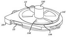
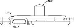
도1은 본 발명에 따른 회전식 혈액펌프(100)의 한 형태를 설명하는 것이다. 회전식 혈액펌프(100)는 환자의 순환계와 연결이 되어 혈액이 인입구(110)를 통해 들어가서 잠시 후 배출구(108)를 통해 빠져나간다.1 illustrates a form of a
혈액은 먼저 도2의 하우징조립부(101) 안에 있는 로터조립부(105)에 의해 회전식 혈액펌프(100)를 통과한다. 로터조립부(105)는 하우징조립부(101)와는 물리적으로 연결되어 있지 않고, 스러스트판(114)과 로터조립부(105) 밑면 사이의 축방향 유체베어링, 로터조립부(105)의 내경과 스러스트 베어링판(114)의 스핀들부 외경 사이의(또는 로터조립부(105) 외부와 하우징조립부(101)의 내경 사이의) 경방향 유체베어링, 그리고 스핀들 자석(119)과 로터 축방향 자석(124) 사이의 축방향 자기베어링에 의해 지탱된다. 이들 베어링의 특성은 참고문헌의 하나인 회전식 혈액펌프라는 제하의 U.S. Application Serial No.10/940,419에 상세히 소개되어 있다. 따라서 작동 시에 로터조립부(105)와 하우징조립부(101) 간의 접촉은 최소화되거나 어떤 경우에서는 접촉이 전혀 없기도 하며, 이런 특성으로 인해 이전의 어떤 설계보다도 마찰이 감소하고 열발생이 최소화되며 소요 동력도 감소한다.The blood first passes through the
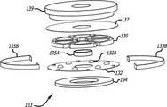
도2는 회전식 혈액펌프(100)를 구성하는 3가지 주요 조립부, 즉 펌프 하우징조립부(101), 모터조립부(103) 그리고 로터조립부(105)를 설명하고 있다.FIG. 2 illustrates three main assembly parts constituting the
일반적으로, 펌프 하우징조립부(101)은 회전식 혈액펌프(100)의 주요부를 차지하고 있으며, 하우징 상판(102)과 하우징 하판(104)를 포함하고 있으며, 이 2개의 부품은 핀(112)에 의하여 하우징 중간판(106)의 위와 아래에 정렬되고 용접되어 있다. 도3A은 하우징 상판(102)의 투시도로서, 옆으로 약간 돌출된 배출구 관로(102B)를 포함하고 있다. 도3B는 하우징 상판(102)의 단면도로서 인입구 관로(102C)를 연결할 수 있도록 돌출부(102A)를 포함하고 있다.In general, the
도4A~4C는 하우징 중간판(106)을 다양한 각도에서 본 형상으로, 하우징 중간 판(106) 개방면의 원주 둘레에 홈(106B)이 나 있으며, 볼류트 형상의 배출구홈(106A)이 이 원주둘레의 홈(106B)에 연결되어 있다. 하우징 상판(102)을 도4A의 윗면에 맞추어 볼트로 체결(또는 용접)하게 되면 이들 2개의 홈(106A, 106B)은 돌출부(102A)와 짝을 이루어 배출구 관로(102B)를 완성하게 된다. 배출구홈(106A)은 배출구의 끝쪽으로 갈수록 폭이 커지는 반면에 개방면의 홈(106B)은 상대적으로 일정한 폭과 형상을 포함하고 있다.4A to 4C show the housing
일반적으로 이 볼류트 형상은 로터조립부(105)의 뒤에서 일정한 '누혈'을 제공하여 혈전 생성의 위험을 최소화하며 혈류의 굄을 방지한다. 도16, 17A, 17B에서 잘 나타나 있듯이, 이 누혈은 로터조립부(105)의 외경과 하우징 중간판(106)의 내경 사이의 원통형 간격에서 시작되어 로터조립부(105) 뒷면 쪽으로 흐른다. 그 다음 혈액은 스러스트판(114)과 로터조립부(105)의 뒷면 사이에서 로터조립부(105)의 중심부로 흐른다. 최종적으로 혈액은 로터조립부(105)의 구멍과 스핀들(114D)의 외경 사이의 틈새 속에서 전방으로 흘러서 스핀들(114D)의 윗면 넘어 되돌아 흐른다. 이 혈액의 순환 경로 상에서 로터조립부(105)의 중심부보다 로터조립부(105)의 원주둘레에서 더 높은 압력변화를 발생시키므로 혈류를 적게 할 수 있다.In general, this volute shape provides a constant 'bleeding' behind the
전형적인 원심펌프의 정상 작동에서는 유체가 로터 블레이드의 배출구에 접근하면서 압력이 상승하는 압력변화를 유발한다. 전형적인 인공심장 이식에서는 이미 언급한 혈류경로와 유사하게, 이 압력을 충분히 높게 하여 로터 주위에서 적당한 누혈을 유지한다. 이런 배치에서는 임펠러 원주 주변의 정압이 펌프의 배출노즐에서의 압력보다 낮다. 이는 볼류트와 배출노즐 형상이 속도수두를 정적수두로 변 환시키고 펌프의 유압효율을 향상시킬 수 있도록 되어 있기 때문이다.In normal operation of a typical centrifugal pump, the fluid approaches the outlet of the rotor blade causing a pressure change in which the pressure rises. In a typical heart transplant, similar to the blood flow pathway already mentioned, this pressure is raised sufficiently to maintain adequate blood leakage around the rotor. In this arrangement, the static pressure around the impeller circumference is lower than the pressure at the discharge nozzle of the pump. This is because the volume of the volute and the discharge nozzle are designed to convert the speed head into a static head and improve the hydraulic efficiency of the pump.
그러나 본 발명의 설계에서는 펌프의 인입구에 비해 배출구의 압력수두가 더 높지 않게 응용하였다. 더욱 특별한 것은 본 발명에서의 '동적수두'가 낮아서, 효과적이고 최적화된 볼류트와 배출노즐을 사용한다면, 구동압력은 누혈경로에서 충분한 누혈을 발생시키에는 충분하지 않을 것이다.However, in the design of the present invention, the pressure head of the outlet is not higher than the inlet of the pump. More particularly, the 'dynamic head' in the present invention is low, so that if an effective and optimized volute and discharge nozzle are used, the driving pressure will not be sufficient to generate sufficient blood leakage in the blood leakage pathway.
따라서, 본 발명에서는 이미 기술한 바 있는 볼류트 형상으로 혈류를 조절하여 펌프 하우징 내의 압력을 증가시킴으로써 누혈경로 상의 구동압력을 증가시킨다. 원환면 형상의 볼류트의 직경이 작아서(예, 2~5mm 의 직경) 볼류트 내의 충분한 압력감소가 발생된다. 이러한 볼류트 내의 압력감소는 결국 펌프(100) 내부의 펌프실에 비해 배출구(108)의 압력이 더 낮아지는 결과를 얻게 된다. 결과적으로 로터조립부(105) 원주 주변의 압력이 높아지고 충분한 구동압력(1.3 lpm 에서는 약 100 mm Hg, 0.7 lpm 이하의 혈류량에서는 25 mm Hg, 2 lpm 이상의 혈류량에서는 200 mm Hg)과 누혈흐름을 발생시켜 혈전 생성의 위험을 최소화한다. 예를 들어, 로터조립부(105)가 2500 RPM 에서 6000 RPM 사이의 속도로 회전하면 구동압력은 배출구에서의 측정 압력보다 50~100% 높아진다.Therefore, in the present invention, the driving pressure on the blood leakage path is increased by adjusting the blood flow in the volute shape described above to increase the pressure in the pump housing. The diameter of the toroidal volute is small (eg 2 to 5 mm in diameter), which results in a sufficient pressure drop in the volute. This pressure reduction in the volute eventually results in a lower pressure of the
도5A~5G는 하우징 하판(104)를 보여주는 것으로, 하우징 하판(104)에는 환상의 움푹파인 부분 또는 칸막이(104A)(도5D~5G 에 잘 나타남)가 포함되어 있으며 이는 본 명세서에서 차후에 기술할 모터조립부(103)와 짝을 이루도록 되어 있다. 도면에서 보듯이 칸막이(104A)는 펌프(100) 밑면의 아래 덮개(115)(도16 에 잘 나타남)와 봉합(예, 레이저 용접)되어 있다.5A-5G show the
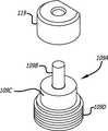
모터조립부(103) 외에 칸막이(104A) 또한 스러스트판(114)(도7A~7D)의 스핀들(114D)의 안쪽에 연결되어 있으며, 이 스러스트판(114)는, 부분적으로 펌프의 축방향 자기베어링을 구성하는 스핀들 자석(119)(도5H, 6D, 6E)과 샤프트조립부(109A(도5H, 5I)를 포함한다. 도5H 에 잘 나타난 바와 같이, 스핀들 자석(119)의 가운데 구멍은 스핀들샤프트(108B)를 미끄러져 운동을 하고 저널기부(109C)에 의해 지지된다. 샤프트조립부(109A)의 나사선 부분(109D)은 나사선이 나 있는 중앙 관로(104C)에 나사체결이 되어 스핀들 자석(119)는 스핀들(114D)의 안쪽에 위치하게 된다. 이렇게 나사체결을 하여 샤프트조립부(109A)의 위치를 유지하게 되면 사용자가 스핀들(114D)의 안쪽에서의 스핀들 자석(119)의 축방향 높이를 조정할 수 있다. 다시 말하면, 사용자가 샤프트조립부(109A)를 돌려서 스핀들 자석(119)을 축방향으로 움직일 수 있다(마커(109E)로 샤프트조립부(109A)의 회전을 시각적으로 관측할 수 있음). 이렇게 하여 사용자는 원하는 대로 축방향 자기베어링을 정밀 조정하여 펌프(100)의 성능을 최적화한다.In addition to the
여기에서는 도시를 하지 않았으나, 또 다른 형태로 위에서 또는 안쪽 면에서부터 하우징 하판(104)의 칸막이(104A)에 접근할 수 있다. 더욱 특별한 것은 스러스트판(114)은 일체형이 아닌 제거가 가능하며 펌프(100)의 바깥에서부터의 접근을 방지한다는 것이다.Although not shown here, in another form, the
도7A~7D에서 보는 바와 같이, 하우징 하판(104)의 윗면에는 일체형 스러스트판(114)을 포함하고 있고, 스러스트판(114)에는 스핀들 자석(119)이 끼워진 스핀들(114D)이 포함되어 있다. 스러스트판(114)에는 최소 3개의 융기부(114A)가 있으 며, 각각의 융기부(114A)는 늘어진 경사면(114B)과 돌출되어 짧고 평편한 표면(114C)으로 구성되어 있다. 예를 들면, 늘어진 경사면(114B)은 스러스트판(114)의 윗면에 상대적으로 약 0.5°~3°정도이다. 로터조립부(105)와 스러스트판(114)의 융기부(114A) 사이의 틈새가 미리 정해진 경계 이하로 떨어지면 이들 융기부(114A)는 유체베어링을 형성한다. 본 발명의 한 형태에서, 정해진 경계는 약 0.0002 인치~0.001 인치의 범위이다. 유체베어링의 또 다른 예가 Woodard 외 다수가 청구한 U.S. Patent No.6,250,880에 보여지며 그 내용은 본 명세서에도 참조하였다.As shown in Figs. 7A to 7D, the upper surface of the housing
도2, 8, 9A, 9B에서 보는 바와 같이 모터조립부(103)는 봉합된 환상의 칸막이(104A) 안에 놓여 있다. 모터조립부(103)는, 도9C~9E에 있는 코일(130)의 권선(130A)에 전기를 통하게 하여 자기장을 생성한다. 각각의 코일(130)의 권선(130A)는 도8의 연성회로(132)의 접점(132A)에 연결되어 있다. 연성회로는 일반적으로 가늘고 둥근 형상이며, 도2의 하우징 하판(104)의 원형 칸막이(104A) 벽의 안에 있는 관로(133)를 통하여 펌프(100)를 빠져나가는 도선(131)의 3개 접점(132B)에 연결된다. 권선(131)의 바깥쪽 부분은 전선(별도 도해 없음)에 연결되고 끝에서는 제어장치(별도 도해 없음)에 연결되어 로터조립부(105)를 구동하기 위한 자기장을 생성하는데 필요한 전력을 제공한다. 연성회로(132)의 접점(132A)의 위치는 여러 다양한 구성이 가능하다. 예를 들어, 연성회로(132)의 원주 근처의 접점(132A)은 연성회로(132)의 중심에 더욱 가깝게 위치할 수 있으며 전기적으로 접점(132A)을 더욱 잘 절연할 수 있다.As shown in Figs. 2, 8, 9A and 9B, the
인지하여야 할 것으로서, 스러스트판(114)이 하우징 하판(104)과 일체형이 아닌 도 다른 형태에서는(예를 들어, 스러스트판(114)이 접착제나 에폭시로 부착되는 경우), 코일(130)의 윗면은 티타늄 포일로 씌워져 있으며, 이 티타늄 포일은 하우징 하판(104)과 용접되어 혈액과 모터조립부(103) 간에 완전한 밀봉을 제공한다. 스러스트판(104) 또한 티타늄 재질일 수도 있으며 하우징 하판(104)에 용접될 수도 있다. 스러스트판(114)가 하우징 하판(104)이 일체를 이루고 있는 형태에서는 티타늄 포일이 필요 없다.As should be appreciated, in other forms where the
모터조립부(103)는 환상의 칸막이(104A)와 유사한 형상을 갖는 후판(134)을 포함한다. 후판(134)은 연성회로(132)의 바로 밑에 위치하고 있으며 코일(130)에 의해 생성된 자기장을 강화시킨다. 일단 기동한 모터조립부(103)는 자기장을 생성하고 스러스트판(114) 위에 위치한 로터조립부(105) 회전을 구동한다.The
또한 모터조립부(103)은 바깥쪽 요소(135B), 안쪽 요소(135A) 그리고 윗쪽 요소(137)를 구성하고 있으며 이들 요소들은 부전도체로 구성되어 코일(130)을 전기적으로 절연하는데 도움이 된다.In addition, the
로터조립부(105)의 외형은 도10A의 로터하우징 하부(126)와 도11A~11D의 로터 상부(118)에 의해 결정된다. 로터 상부(118)와 로터하우징 하부(126)는 스러스트판(114)의 스핀들(114D)의 원주 둘레에 맞는 크기의 중앙 구멍을 포함하고 있다. 로터 상부(118)에는 곡선의 임펠러 블레이드(118A)가 있어 유입 혈액을 배출구(108) 밖으로 밀어낸다. 각각의 블레이드(118A)는 필요한 혈류량과 압력을 만족시키기 위한 높이와 곡선을 갖는다. 또한 로터조립부(105)는 원하는 혈류량의 범위 에 적절한 공칭 혈류량과 압력수두에 기반을 둔 크기와 형상을 갖고, 펌프는 이 혈류량의 범위에서 작동할 수 있도록 설계될 것이다. 한 형태에서는 혈류량의 범위가 약 0.5~2.0 lpm 이며 약 1.3 lpm 정도가 최적의 혈류량이다. 도11D에서 잘 볼 수 있듯이, 로터 상부(118)의 윗면(118B)은 전체적으로 각이진 경사로의 형상이다. 이전의 기술과는 다르게 윗면(118B)의 각도가 상대적으로 얄팍하여 전체가 더 얇은 형상을 보인다. 예를 들어, 윗면(118B)은 약 10° 이하의 각도를 가져도 좋으며 특히 수평면에 대해 3.80°~4.00°이면 좋다.The outer shape of the
로터조립부(105)는, 로터 축방향 자석조립부(124), 로터 자석(122) 그리고 후판(120) 등의 3개 부품으로 구성되어 있다. 도2와 도16에서 잘 볼 수 있는 바와 같이, 후판(120)과 로터 자석(122)은 거의 같은 직경이며 후판(120)을 로터 자석(122)의 윗면에 놓이도록 하여 자기장을 강화한다. 도13A과 도13B에서의 로터 축방향 자석조립부(124)는 로터조립부(105)의 내부에 놓이며 도16에서 보는 것처럼 로터 자석(122)과 후판(120)의 중앙에 있는 구멍 안쪽에 위치한다. 로터 자석조립부(122)와 후판(120)을 로터 하우징 하판(126) 안에 유지하기 위해서 로터 하우징하판(126) 안쪽 공간의 둘레에 스페이서(123)을 사용하면 좋다.The
본 발명의 한 형태로서, 도12A와 도12B에서와 같이 로터 자석(122)은 교차되는 극성을 갖는 여러 개의 자석으로 구성되어 있다. 전력이 모터조립부(103)에 작용하면 코일(130)은 로터 자석(122)을 구동하는 자기장을 생성하고 로터조립부(105)를 회전시킨다.As one embodiment of the present invention, as shown in Figs. 12A and 12B, the
로터 자석(122)은 가급적 영구자석이면 좋고 이는 모터조립부(103)의 후 판(134)에 끌어 당겨진다. 이 당기는 힘에 의해 로터조립부(105)는 스러스트판(114) 쪽으로 당겨지고 로터조립부(105)에 많은 축방향 부하를 발생시킨다. U.S. Patent Nos. 6,234,772와 6,250,880에서 보는 바와 같이 이전의 회전식 혈액 펌프 설계는 이 축방향 부하를 극복하기 위해 기본적으로 스러스트 유체 베어링에 의존한다. 그러나 이 유체 베어링은 로터와 스러스트판 사이의 얇은 혈액층을 이용하는 것이므로 그 혈액이 축방향의 부하 전체를 지탱하여야만 한다. 결과적으로, 혈액세포는 강한 전단력에 의해 더욱 쉽게 손상될 수 있어서 용혈이나 응고 등의 심각한 부작용을 초래할 수 있다. 또한 부하가 증가하면 이 유체 베어링을 지탱하기 위한 힘도 증가한다. 유체 베어링이 많은 부하를 받게 되면 펌프는 상당량의 동력을 부담하여야 한다.The
본 발명은, U.S.Application Serial No.10/940,419(이미 참조한 바가 있음)에서 상세히 기술되었던, 유체 베어링과 축방향 자기베어링 간의 축방향 부하를 분산시킨다. 그러나 본 명세서에 이러한 특성에 대해 부연할 필요가 있다.The present invention distributes the axial load between the fluid bearing and the axial magnetic bearing, as described in detail in U.S. Application Serial No. 10 / 940,419 (which has already been referenced). However, it is necessary to elaborate on these characteristics herein.
이미 기술한 대로 유체 베어링은 스러스트판(114) 위에 3개의 융기부를 포함하고 있으며, 로터조립부(105)가 스러스트판(114)에 근접한 위치에 도달하면 로터의 표면과 스러스트판(114) 사이의 상대적인 운동에 의하여 로터조립부(105)에 윗쪽 방향의 힘을 작용시킨다. 본 발명에서는 모든 융기부(114A)의 누적 총면적이 스러스트판(114) 전체 면적의 약 40%~90% 이내이다. 이런 특성의 3개 돌출부에 의해 본 발명 펌프에 필요한 유체 베어링 효과를 제공한다.As previously described, the fluid bearing includes three ridges on the
도14, 16, 17A와 17B 와 같이, 축방향 자기베어링은 로터 축방향 자석(124) 과 스핀들 자석(119)을 포함한다. 도14과 같은 형태에서는 로터 축방향 자석(124)과 스핀들 자석(119)은 축방향 상에서 서로 반대 방향 놓인 자기장을 갖는다. 결과적으로 두 자성체(119, 124)는 서로 축방향으로 당기는 안정된 상태에 놓여 로터조립부(105)의 축방향 부하를 감소시킨다. 도14A는 두 자성체(119, 124)의 극성이 도14 경우와는 반대인 형태를 보여준다.As shown in Figures 14, 16, 17A and 17B, the axial magnetic bearing includes a rotor
두 자성체(119, 124)에 의해 생성된 축방향의 예비부하 또는 편심력은 축방향 자기베어링을 조립하면서 조절할 수 있다. 펌프 후방을 향하고 있는 로터에 충분한 힘을 작용시켜서 로터조립부(105)를 안정시키고 최고 속도에서의 운동을 방지하도록 한다. 이런 예비부하를 얻기 위한 최소한의 힘을 작용시켜야 하며 과도한 힘은 스러스트 유체베어링의 동력소실을 증가시키며(본 명세서의 다른 부분에서 기술되었음) 용혈을 증가시킨다.The axial preload or eccentric force generated by the two
스핀들 자석(119)의 최적 위치는, 실물모형의 순환계에서 기능 실험을 하여 실험적으로 결정할 수 있다. 최대속도는 많은 펌프의 유압성능을 보여주는 요소이다. 일단 최대속도가 결정되면 각각의 펌프를 압력 105 mm Hg에서 2.0 lpm 의 혈류량에 조절하고, 로터조립부(105)에서 불안정한 요소가 감지될 때까지(펌프 하우징조립부(101)에서 발생되는 소리가 변화가 감지될 때까지) 스핀들 자석(119)의 위치를 조절한다. 불안정 경계가 감지되면 샤프트조립부(109A)를 그 경계점 아래(예 : 하우징 하판(104) 쪽으로)로 돌린다. 로터 축방향 자석(124)에 대한 스핀들 자석(119)의 상대적인 높이는 다양하게 설정할 수 있다.The optimum position of the
도15A는 축방향 자기베어링의 또 다른 형태를 보여주는 것으로 스핀들 자 석(119)과 로터 축방향 자석(124) 각각은 2개로 나뉜 자기영역으로 구성되고 이들 2개 영역은 축방향 상에서 서로 반대되는 극을 갖도록 정렬되어 있다. 예를 들어, 로터 축방향 자석(124) 중 위쪽에 있는 자기영역(124A)은, 그 북극이 아래쪽 자기영역(124B)의 북극을 향해 아래로 마주하도록 놓여 있다. 비슷한 방법으로, 스핀들 자석(119) 중 위쪽에 있는 자기영역(119A)은, 그 남극이 아래쪽 자기영역(119B)의 남극을 향해 아래로 마주하도록 놓여 있다. 이렇게 하면, 로터 축방향 자석(124)의 중심과 스핀들 자석(119)의 중심 사이에는 당기는 힘이 발생되고, 한 자성체의 끝과 다른 자성체의 중심 사이에는 미는 힘이 발생되어 축방향 자기베어링은 축방향의 부하를 감소시킨다. 예를 들면, 로터 축방향 자석(124)의 바깥쪽 남극은 스핀들 자석(119)의 안쪽 남극과 미는 힘을 생성한다. 이렇게 로터 축방향 자석(124)과 스핀들 자석(119) 사이에 미는 힘과 당기는 힘이 동시에 발생함으로써 로터조립부(105)에 부과되어야 할 축방향 부하의 일부분이라도 감소시킨다.Fig. 15A shows another form of axial magnetic bearing, in which the
또 다른 형태에서는 스핀들 자석(119)과 로터 축방향 자석(124)은 몇 가지의 다른 자기영역으로 구성되어 있다. 도15B 의 예시와 같이, 스핀들 자석(119)은 하나의 N-S 영역을 갖는 반면에 로터 축방향 자석(124)은 그 위쪽에는 S-N 영역을, 그 아래쪽에는 N-S 영역을 갖도록 되어 있다. 이와 비슷하게 도15C 에서는, 스핀들 자석(119)은 그 위쪽에 N-S 영역을, 그 아래쪽에는 S-N 영역을 갖도록 되어 있다.In another form, the
도14 및 도15A~C 에서 예시한 형태에서는, 두 자성체(119,124)의 자성을 높이거나 낮춤으로써, 또는 간단하게 하우징 하판(104)의 중앙관로(104C)에 나사 체결되는 샤프트(109)를 조정하여 펌프 내의 스핀들 자석(119)의 높이를 조절함으로 써 축방향 자기베어링에 의해 발생하는 힘을 조절할 수 있다. 도14와 15A 에서와 같이 스핀들 자석(119)은 로터 축방향 자석(124) 보다 상대적으로 높은 곳에 위치하면 로터조립부(105)에 가해지는 상향의 축방향 힘을 최대화하고, 높이가 상대적으로 낮으면 로터조립부(105)에 가해지는 상향의 축방향 힘을 최소화한다.In the embodiment illustrated in FIGS. 14 and 15A-C, the
본 발명의 진화된 형태로, 로터 축방향 자석(124)은 영구자석으로 되어 있고 스핀들 자석(119)은 강자성체로 되어 있을 수 있으며, 이와는 반대의 경우도 가능하다. 이와 비슷하게, 각각의 스핀들 자석(119)과 로터 축방향 자석(124)은 2개의 분리된 자기영역으로 구성될 수도 있으며, 이 경우 한쪽 자기영역은 영구자석이고 다른 쪽 자기영역은 강자성체로 이루어진다. 물론 이들 형태의 자성물질은 본 발명에서 기술한 축방향 부하를 제공하기 위한 여러 형태 중의 하나를 따른다.In an evolved form of the invention, the rotor
본 발명에 따른 또 다른 형태의 축방향 자기베어링이 가능하다. 예를 들어, 로터 축방향 자석(124)은 로터조립부(105)의 바깥쪽 둘레에 배치되고, 스핀들 자석(119)은 하우징 하판(106)의 옆벽면에 매립할 수 있다. 이런 방법으로 두 자성체의 서로 다른 위치에 의해 축방향의 힘을 발생하고 로터조립부(105)의 하향 예비부하를 보상할 수 있다.Another form of axial magnetic bearing according to the invention is possible. For example, the rotor
도16에서 보는 방와 같이 인입구 관로(102C)를 통해 펌프(100)으로 들어간 혈액은 임펠러 블레이드(118A)에 의해 로터 상부를 넘어 볼류트로 분산되고, 펌프(100) 옆면의 배출구(108) 또는 로터조립부(스러스트 유체베어링 작동을 위한 유체를 공급하는) 밑에 있는 로터의 외부로 밀려나가게 되며, 저널베어링 작동을 위한 유체를 공급하는 로터조립부(105)와 스핀들 사이의 틈새로 유입된다.Blood entering the
어떤 경우에는 펌프(100)을 통하는 혈류의 운동에 기인하여 로터조립부(105)에 작용되는 경방향의 편심이 있을 수가 있다. 예를 들어, 혈액이 펌프(100)을 빠져나가게 되면 배출구에서의 배출 압력이 상승하여 로터조립부(105)에 전술한 편심을 유발한다. 도5G, 6C, 6D, 6E 및 18E고 같은 형태에서는, 경방향으로 비대칭 또는 비원형의 스핀들 자석(119)을 축방향 자기베어링 안에 사용하여 비대칭 자기장을 생성함으로써 이 경방향 편심을 보상할 수 있다. 즉, 스핀들 자석은 도6D와 6E의 자형 스핀들 자석(119)이나 도6C의 스핀들 자석(117)의 "D"자형상과 같은 비대칭 또는 비원형의 단면형상을 가질 수 있다. 정해진 방향과 크기를 갖고 편심에 반대되는 자기력을 증가시킬 수 있도록 이 형상의 위치를 정할 수 있다. 특히 스핀들 자석(119)의 곡선부는 평편한 쪽보다 상대적으로 더 큰 자기장을 만든다. 다시 말해서, 스핀들 자석(119)의 형상은, 그 중심이 축방향 자기베어링의 회전축과는 어긋나게 되고 결과적으로 로터조립부(105)의 로터 축방향 자석(124)에 상대적으로 중심이 어긋나게 되는 형상을 갖게 된다. 이렇게, 큰 자기장을 갖는 스핀들 자석(119)의 면이 편심의 방향과는 반대되게 위치를 잡고(편심이 스핀들 자석(119)의 평편한 면을 향하도록), 그 방향에서 로터 축방향 자석(124)에 더 많은 힘을 가하게 되어 로터조립부(105)에 대한 편심 효과를 감소 또는 상당량 제거할 수 있다. In some cases, there may be a radial eccentricity acting on the
본 발명의 한 또 다른 형태로, 경사면, 테이퍼, 패드와 같이 스러스트판(114)이나 하우징 중간판(106)의 내부 원주면을 따라서 기하학적 형상이 변하는 표면 특성에 의해 이러한 편심을 보상할 수 있다. 하우징 중간판(100)의 한쪽에만 불균등하게 이런 형상을 주어, 펌프(100)의 한족에만 유체베어링이 형성하고 경방향의 편심력을 생성한다. 이러한 경방향 유체베어링의 위치를 적절히 결정함으로써 배출구(108) 편심을 많이 감소시킬 수 있다.In another aspect of the present invention, this eccentricity can be compensated for by surface characteristics that vary in geometry along the inner circumferential surface of the
또 다른 형태로, 스핀들(114D)과 로터 축방향 자석(124)의 중심과 스핀들 자석(116)의 중심을 어긋나게 하여 이 경방향 편심을 보상할 수도 있다. 예를 들어, 도18A 와 같이 스핀들 자석(116)을 스핀들(114D) 중심의 한쪽에 치우치게 위치시킨다. 스핀들 자석(116)과 로터 축방향 자석(124)의 배치에 따라서, 스핀들 자석(116)의 어긋난 중심은 로터조립부(105)가 회전하면서 경방향의 알짜 힘을 발생시킨다. 이렇게 편심과 동일한 크기를 갖고 방향이 반대인 경방향 힘을 생성함으로써 혈액이 펌프(100)를 빠져나가면서 발생되는 경방향 편심을 상쇄할 수 있다.In another form, the radial eccentricity may be compensated by shifting the center of the
본 발명의 다른 관점은, 로터 자석(122), 스테이터 후판(120), 그리고 로터 축방향 자석(124) 간의 축방향 부하와, 펌프의 유체정역학적 압력, 그리고 스러스트판(114)에 의한 유체베어링 등의 상호작용이다. 이에 대해서는 아래에서 더욱 상세하게 기술한다.Another aspect of the invention is an axial load between the
펌프(100)가 작동하는 동안 로터 상부(118)의 곡면의 임펠러 블레이드는 유체정역학적 압력을 발생하고, 그 압력의 대부분은 배출구(108)를 통하는 유용한 흐름을 만들어 낸다. 모든 원심펌프에서 유체정역학적 압력은 로터와 하우징의 모든 젖은 표면에 작용한다. 이 유체정역학적 압력의 합은 베어링이 지지하여야 할 로터 측 알짜 힘을 생성한다. 이런 힘을 측정하기는 어렵다: 그러나, 이미 알려진 수치적 유체동력학 분석에 의해 좀 더 쉽게 예측할 수는 있다. 수치적 유체동력학 (CFD : Computational Fluid Dynamics)는 일종의 유한요소 프로그램으로서 펌프의 모델을 설정하고 성능을 예측하는데 사용한다. 이런 분석 결과를 이용하여, 유체성능, 효율, 힘 그리고 전단력 등과 같이, 특정 설계에서 예상되는 파라메타들을 결정할 수 있다. 한 가지 상업적 프로그램인 ANSYS CFX-5을 사용하여 본 발명에 따른 펌프(100)의 CFD 모델을 만들었다. 후면, 하우징 틈새 그리고 유체베어링을 포함한 하나의 완전한 로터조립부(105)의 회기 모형을 사용하여 로터조립부(105)에 미치는 힘과 로터조립부(105) 뒤에서의 누혈의 값을 구하였다.While the
계산된 레이놀즈 수는 최대 236으로서 층류영역 안에 있으며 전이영역 2000 보다는 아래이므로 층류모형을 사용하였다. 레이놀즈 수의 식은 :The calculated Reynolds number is up to 236, which is in the laminar flow zone and below the transition zone 2000, so the laminar flow model is used. The Reynolds number formula is:
R = ρVD/μ 이며,R = ρVD / μ,
여기서 ρ: 밀도(1.0 kg/l)Where ρ: density (1.0 kg / l)
V : 속도(6.5 m/s) V: Speed (6.5 m / s)
D : 틈새(0.0127 cm) D: clearance (0.0127 cm)
μ : 점도(3.5 cps) μ: viscosity (3.5 cps)
도19는 로터조립부(105)에 가해지는 유체정역학적 압력의 등압에 대한 도해이다. 압력 단위는 파스칼(1파스칼 = 0.0075 mm Hg)이다. 소프트웨어의 함수 계산기에 의하면 로터조립부(105)의 중심부에 작용하는 평균압력이 9754 파스칼 또는 73.15 mm Hg(1.415 psi)이다. 로터조립부(105) 환상의 면적은 1.041 평방인치로, 중앙부에 미치는 축방향의 유체정역학적 알짜 힘은 1.472 파운드이며, 펌프(100) 하판의 뒤쪽을 향한다.19 is an illustration of the isostatic pressure of hydrostatic pressure applied to the
도20는 로터조립부(105)의 하부, 즉 로터 하우징 하판(126)에 작용하는 유체정역학적 압력 및 유체동역학적 압력에 대한 등압도이다. 도20에서는 스러스트판(114) 위의 3개의 융기부(114A)의 외관을 볼 수 있으며, 이들 베어링에 의해 각기 다른 압력 영역을 갖는다. 소프트웨어의 함수 계산기에 의하면 3개의 융기부(114A) 바깥부분의 유체정역학적 압력은 8395.72 파스칼 또는 62.97 mm Hg(1.219 psi)이다. 로터 하우징 하판의 면적은 1.041 평방인치로서 펌프(100)의 후방으로부터 멀어지는 방향으로 유체정역학적 힘 1.27 파운드를 발생시킨다.20 is an isometric view of hydrostatic pressure and hydrodynamic pressure acting on the lower portion of the
이렇게 CFD 계산에 의하면 로터조립부(105)에 작용하는 유체정역학 및 유체동역학적 축방향 알짜 힘(즉, 로터조립부(105)의 상판과 로터조립부(105)의 하판에 작용하는 힘의 차이)은 0.202 파운드이며 펌프의 후방을 향한다. 이 유체정역학 및 유체동역학적 축방향 알짜 힘은 모터자석(122)과 후판(134)의 작용에 의해 발생되는 힘과도 관련이 되어 있다. 모터 자석(122)과 후판(134)의 전형적인 당기는 힘은 약 1.1 파운드이다. 그러므로, 융기부(114A)에 의해 형성되는 유체베어링은, 유체정역학 및 유체동역학적 축방향 알짜 힘(0.202 파운드)과 모터 자석(122)과 후판(134) 간의 당기는 힘(1.1 파운드)이 결합된, 최소 1.302 파운드의 축방향 힘을 상쇄하여야 한다. 다시 말하면, 유체버어링은 이들 두 힘을 모두 상쇄할 수 있는 만큼의 힘을 생성하여야 하며, 이 힘에 의하여 정상적인 작동을 하는 동안에는 로터조립부(105)가 하우징조립부(101)과는 접촉을 하지 않거나 최소의 접촉하는 위치를 유지하여야 한다.Thus CFD calculation according to the hydrostatic and hydrodynamic axial net force acting on the rotor assembly 105 (that is, the difference between the force acting on the upper plate of the
끝으로 펌프의 작동을 기술한다. 혈액펌프(100)는 인입구(110)와 배출 구(108)를 통해서 환자의 순환계에 연결된다. 사용자는 혈액펌프의 제어기를 가동하여 혈액펌프를 작동시킨다.제어기는 적절한 전류를 연성회로에 보내고, 다시 연성회로에 의해 코일(130)에 이 전류를 분배한다. 코일(13)의 권선(132)를 통하는 전류는 자기장을 생성하여 모터 자석(122)와 상호작용하며 로터조립부(105)를 회전시킨다. 스핀들 자석(119)과 로터 축방향 자석(124)은 상호작용하여 축방향 자기베어링을 만들어 로터조립부(105)가 회전하는 동안 로터조립부(105)의 축방향 위치를 유지하는데 기여한다. 로터조립부(105)가 회전하면, 스러스판(114) 위의 융기부(114A)는 스러스트 유체베어링을 만들고, 이 스러스트 유베베어링에 의해 축방향의 힘이 로터조립부(105)에 전해진다.Finally, describe the operation of the pump. The
로터조립부(105)가 회전하면서 로터 하우징 상판(118)의 임펠러 블레이드(118A)는 인입구(110) 및 인입구 관로(102C)로부터 배출구(108)를 통해 혈액을 토출한다. 이렇게 하여 회전하는 로터조립부(105)는 환자의 혈액을 혈액펌프(100)을 통과하게 하여 혈액순환을 도와준다.As the
본 발명은 특정 형태나 응용의 관점에서 기술하였으나, 보편적인 기술을 보유한 사람이라면 본 발명의 청구의 의도와 범위를 벗어나지 않고 더 많은 응용을 할 수 있다. 따라서, 여기서 소개한 도면과 기술은 본 발명의 이해를 돕기 위한 예시인 것이며 이의 범위를 제한하지 않아야 한다.Although the present invention has been described in terms of specific forms and applications, those having universal skill in the art can make more applications without departing from the spirit and scope of the claims of the present invention. Accordingly, the drawings and techniques introduced herein are examples to aid the understanding of the present invention and should not limit the scope thereof.
Claims (42)
Translated fromKoreanApplications Claiming Priority (2)
| Application Number | Priority Date | Filing Date | Title |
|---|---|---|---|
| US78773806P | 2006-03-31 | 2006-03-31 | |
| US60/787,738 | 2006-03-31 |
Publications (1)
| Publication Number | Publication Date |
|---|---|
| KR20090074110Atrue KR20090074110A (en) | 2009-07-06 |
Family
ID=38564269
Family Applications (1)
| Application Number | Title | Priority Date | Filing Date |
|---|---|---|---|
| KR1020087026573ACeasedKR20090074110A (en) | 2006-03-31 | 2007-03-30 | Rotary Blood Pump |
Country Status (10)
| Country | Link |
|---|---|
| US (5) | US20070231135A1 (en) |
| EP (1) | EP2005376A2 (en) |
| JP (2) | JP2009532131A (en) |
| KR (1) | KR20090074110A (en) |
| CN (2) | CN103170020A (en) |
| AU (1) | AU2007233078B2 (en) |
| CA (1) | CA2647151A1 (en) |
| IL (1) | IL194386A0 (en) |
| SG (1) | SG170817A1 (en) |
| WO (1) | WO2007115222A2 (en) |
Cited By (3)
| Publication number | Priority date | Publication date | Assignee | Title |
|---|---|---|---|---|
| KR101309268B1 (en)* | 2011-12-09 | 2013-09-16 | 주식회사 세종파마텍 | A feeder |
| KR20170129792A (en) | 2015-03-18 | 2017-11-27 | 아비오메드 유럽 게엠베하 | Blood pump |
| KR20180111977A (en) | 2016-02-11 | 2018-10-11 | 아비오메드 유럽 게엠베하 | Blood pump |
Families Citing this family (92)
| Publication number | Priority date | Publication date | Assignee | Title |
|---|---|---|---|---|
| AUPO902797A0 (en)* | 1997-09-05 | 1997-10-02 | Cortronix Pty Ltd | A rotary blood pump with hydrodynamically suspended impeller |
| AUPP995999A0 (en) | 1999-04-23 | 1999-05-20 | University Of Technology, Sydney | Non-contact estimation and control system |
| AUPR514201A0 (en)* | 2001-05-21 | 2001-06-14 | Ventrassist Pty Ltd | Staged implantation of ventricular assist devices |
| AU2003904032A0 (en)* | 2003-08-04 | 2003-08-14 | Ventracor Limited | Improved Transcutaneous Power and Data Transceiver System |
| EP1670524A4 (en)* | 2003-10-09 | 2012-12-26 | Thoratec Corp | Impeller |
| US20060083642A1 (en) | 2004-10-18 | 2006-04-20 | Cook Martin C | Rotor stability of a rotary pump |
| US8152035B2 (en)* | 2005-07-12 | 2012-04-10 | Thoratec Corporation | Restraining device for a percutaneous lead assembly |
| US20070142696A1 (en)* | 2005-12-08 | 2007-06-21 | Ventrassist Pty Ltd | Implantable medical devices |
| KR20090074110A (en)* | 2006-03-31 | 2009-07-06 | 오퀴스 메디컬 코포레이션 | Rotary Blood Pump |
| US20080133006A1 (en)* | 2006-10-27 | 2008-06-05 | Ventrassist Pty Ltd | Blood Pump With An Ultrasonic Transducer |
| US20080200750A1 (en)* | 2006-11-17 | 2008-08-21 | Natalie James | Polymer encapsulation for medical device |
| JP5171953B2 (en) | 2008-06-23 | 2013-03-27 | テルモ株式会社 | Blood pump device |
| GB0816883D0 (en)* | 2008-09-15 | 2008-10-22 | Univ Aston | Rotary blood pump |
| US8550974B2 (en) | 2008-11-13 | 2013-10-08 | Robert Jarvik | Sub-miniature electromechanical medical implants with integrated hermetic feedthroughs |
| EP2372160B1 (en) | 2008-12-08 | 2014-07-30 | Thoratec Corporation | Centrifugal pump device |
| JP5378010B2 (en) | 2009-03-05 | 2013-12-25 | ソラテック コーポレーション | Centrifugal pump device |
| CN102341600B (en) | 2009-03-06 | 2014-12-10 | 胸腔科技有限公司 | Centrifugal pump device |
| US8366418B2 (en)* | 2009-06-12 | 2013-02-05 | Gulfstream, Inc. | Magnetic centrifugal pump |
| JP5443197B2 (en) | 2010-02-16 | 2014-03-19 | ソラテック コーポレーション | Centrifugal pump device |
| US9555174B2 (en) | 2010-02-17 | 2017-01-31 | Flow Forward Medical, Inc. | Blood pump systems and methods |
| US9662431B2 (en) | 2010-02-17 | 2017-05-30 | Flow Forward Medical, Inc. | Blood pump systems and methods |
| KR101845213B1 (en) | 2010-02-17 | 2018-05-18 | 플로우 포워드 메디컬, 인크. | System and method to increase the overall diameter of veins |
| JP5572832B2 (en) | 2010-03-26 | 2014-08-20 | ソーラテック コーポレイション | Centrifugal blood pump device |
| CA2802215A1 (en) | 2010-06-22 | 2011-12-29 | Thoratec Corporation | Apparatus and method for modifying pressure-flow characteristics of a pump |
| JP5898190B2 (en) | 2010-06-22 | 2016-04-06 | ソラテック コーポレーション | Fluid delivery system and method for monitoring a fluid delivery system |
| JP5681403B2 (en) | 2010-07-12 | 2015-03-11 | ソーラテック コーポレイション | Centrifugal pump device |
| USD669585S1 (en) | 2010-08-20 | 2012-10-23 | Thoratec Corporation | Implantable blood pump |
| WO2012024567A1 (en) | 2010-08-20 | 2012-02-23 | Thoratec Corporation | Assembly and method for stabilizing a percutaneous cable |
| JP5577506B2 (en) | 2010-09-14 | 2014-08-27 | ソーラテック コーポレイション | Centrifugal pump device |
| EP2693609B1 (en) | 2011-03-28 | 2017-05-03 | Thoratec Corporation | Rotation and drive device and centrifugal pump device using same |
| USD671646S1 (en) | 2011-04-21 | 2012-11-27 | Thoratec Corporation | Implantable blood pump |
| EP2744539B1 (en) | 2011-08-17 | 2022-11-02 | Artio Medical, Inc. | System to increase the overall diameter of a peripheral artery |
| KR102062132B1 (en)* | 2011-08-17 | 2020-01-03 | 플로우 포워드 메디컬, 인크. | Blood pump systems and methods |
| JP6083929B2 (en) | 2012-01-18 | 2017-02-22 | ソーラテック コーポレイション | Centrifugal pump device |
| US10258730B2 (en) | 2012-08-17 | 2019-04-16 | Flow Forward Medical, Inc. | Blood pump systems and methods |
| CN103055363B (en)* | 2013-01-22 | 2015-04-15 | 上海交通大学 | Vortex type implantable pulse ventricle assisting blood pump |
| US9371826B2 (en) | 2013-01-24 | 2016-06-21 | Thoratec Corporation | Impeller position compensation using field oriented control |
| US9556873B2 (en) | 2013-02-27 | 2017-01-31 | Tc1 Llc | Startup sequence for centrifugal pump with levitated impeller |
| US9144638B2 (en)* | 2013-03-14 | 2015-09-29 | Thoratec Corporation | Blood pump rotor bearings |
| DE102013007190A1 (en)* | 2013-04-25 | 2014-10-30 | Fresenius Medical Care Deutschland Gmbh | Cassette module with integrated centrifugal pump unit |
| US9713663B2 (en) | 2013-04-30 | 2017-07-25 | Tc1 Llc | Cardiac pump with speed adapted for ventricle unloading |
| US10052420B2 (en) | 2013-04-30 | 2018-08-21 | Tc1 Llc | Heart beat identification and pump speed synchronization |
| CN103341220B (en)* | 2013-07-22 | 2015-07-22 | 福州大学 | Valveless volumetric heart pump |
| CN103591028B (en)* | 2013-10-23 | 2016-08-24 | 北京精密机电控制设备研究所 | A kind of apex of the heart implanted centrifugal pump for treating cardiac failure |
| US9623161B2 (en) | 2014-08-26 | 2017-04-18 | Tc1 Llc | Blood pump and method of suction detection |
| EP3256183B1 (en) | 2015-02-11 | 2025-08-13 | Tc1 Llc | Heart beat identification and pump speed synchronization |
| EP3256185B1 (en) | 2015-02-12 | 2019-10-30 | Tc1 Llc | System and method for controlling the position of a levitated rotor |
| US10371152B2 (en) | 2015-02-12 | 2019-08-06 | Tc1 Llc | Alternating pump gaps |
| EP3256184B1 (en) | 2015-02-13 | 2020-04-08 | Tc1 Llc | Impeller suspension mechanism for heart pump |
| EP3069741A1 (en)* | 2015-03-17 | 2016-09-21 | Berlin Heart GmbH | Heart pump device and method of operating the same |
| WO2016187057A1 (en) | 2015-05-15 | 2016-11-24 | Thoratec Corporation | Improved axial flow blood pump |
| US20170016449A1 (en)* | 2015-07-14 | 2017-01-19 | Hamilton Sundstrand Corporation | Axial-flux induction motor pump |
| EP3135933B1 (en)* | 2015-08-25 | 2019-05-01 | ReinHeart GmbH | Active magnetic bearing |
| US10117983B2 (en) | 2015-11-16 | 2018-11-06 | Tc1 Llc | Pressure/flow characteristic modification of a centrifugal pump in a ventricular assist device |
| WO2017120451A2 (en) | 2016-01-06 | 2017-07-13 | Bivacor Inc. | Heart pump with impeller rotational speed control |
| AU2017257508B2 (en) | 2016-04-29 | 2021-10-14 | Artio Medical, Inc. | Conduit tips and systems and methods for use |
| WO2017192119A1 (en)* | 2016-05-02 | 2017-11-09 | Vadovations, Inc. | Heart assist device |
| IT201700013374A1 (en)* | 2017-02-07 | 2018-08-07 | In10Sivecare S R L | Peristaltic pump and method for its realization |
| EP3606577B1 (en) | 2017-04-05 | 2025-07-30 | Bivacor Inc. | Heart pump drive and bearing |
| CA3066361A1 (en) | 2017-06-07 | 2018-12-13 | Shifamed Holdings, Llc | Intravascular fluid movement devices, systems, and methods of use |
| US10349810B2 (en)* | 2017-08-08 | 2019-07-16 | Haier Us Appliance Solutions, Inc. | Pump assembly for a dishwashing appliance |
| WO2019094963A1 (en) | 2017-11-13 | 2019-05-16 | Shifamed Holdings, Llc | Intravascular fluid movement devices, systems, and methods of use |
| CN109847127A (en)* | 2017-11-30 | 2019-06-07 | 上海微创医疗器械(集团)有限公司 | Magnetic liquid suspension formula centrifugal blood pump |
| CN112004563B (en) | 2018-02-01 | 2024-08-06 | 施菲姆德控股有限责任公司 | Intravascular blood pump and methods of use and manufacture |
| US10947986B2 (en)* | 2018-07-11 | 2021-03-16 | Ch Biomedical (Usa) Inc. | Compact centrifugal pump with magnetically suspended impeller |
| US12161857B2 (en) | 2018-07-31 | 2024-12-10 | Shifamed Holdings, Llc | Intravascular blood pumps and methods of use |
| EP3633217A1 (en)* | 2018-10-02 | 2020-04-08 | Berlin Heart GmbH | Bearing assembly and rotation fluid pump |
| WO2020073047A1 (en) | 2018-10-05 | 2020-04-09 | Shifamed Holdings, Llc | Intravascular blood pumps and methods of use |
| US11318295B2 (en)* | 2019-02-28 | 2022-05-03 | Heartware, Inc. | HVAD rinse via a non-uniform thrust bearing gap |
| CN110464895B (en)* | 2019-06-26 | 2022-02-22 | 上海微创心力医疗科技有限公司 | Magnetic liquid suspension type blood pump |
| WO2021011473A1 (en) | 2019-07-12 | 2021-01-21 | Shifamed Holdings, Llc | Intravascular blood pumps and methods of manufacture and use |
| US11654275B2 (en) | 2019-07-22 | 2023-05-23 | Shifamed Holdings, Llc | Intravascular blood pumps with struts and methods of use and manufacture |
| EP4501393A3 (en) | 2019-09-25 | 2025-04-09 | Shifamed Holdings, LLC | Catheter blood pumps and collapsible pump housings |
| WO2021062265A1 (en) | 2019-09-25 | 2021-04-01 | Shifamed Holdings, Llc | Intravascular blood pump systems and methods of use and control thereof |
| US12121713B2 (en) | 2019-09-25 | 2024-10-22 | Shifamed Holdings, Llc | Catheter blood pumps and collapsible blood conduits |
| CN110721357B (en)* | 2019-10-18 | 2022-10-11 | 上海微创心力医疗科技有限公司 | Impeller assembly and suspension type blood pump |
| CN114728116A (en) | 2019-11-12 | 2022-07-08 | 费森尤斯医疗护理德国有限责任公司 | Blood treatment system |
| EP4058088A1 (en) | 2019-11-12 | 2022-09-21 | Fresenius Medical Care Deutschland GmbH | Blood treatment systems |
| WO2021096706A1 (en) | 2019-11-12 | 2021-05-20 | Fresenius Medical Care Deutschland Gmbh | Blood treatment systems |
| EP4058095A1 (en) | 2019-11-12 | 2022-09-21 | Fresenius Medical Care Deutschland GmbH | Blood treatment systems |
| EP4058079A1 (en) | 2019-11-12 | 2022-09-21 | Fresenius Medical Care Deutschland GmbH | Blood treatment systems |
| EP4058087A1 (en) | 2019-11-12 | 2022-09-21 | Fresenius Medical Care Deutschland GmbH | Blood treatment systems |
| EP4072650A4 (en) | 2019-12-11 | 2024-01-10 | Shifamed Holdings, LLC | Descending aorta and vena cava blood pumps |
| TWI724851B (en)* | 2020-04-01 | 2021-04-11 | 訊凱國際股份有限公司 | Thinned pump |
| CN112546425B (en)* | 2020-10-29 | 2021-07-23 | 苏州心擎医疗技术有限公司 | Magnetic levitation motor and magnetic levitation blood pump |
| CN114652952B (en)* | 2020-12-23 | 2025-08-19 | 上海微创心力医疗科技有限公司 | Bearing for blood pump, blood pump and ventricular assist circulation device |
| CN112999510B (en)* | 2021-02-24 | 2025-08-22 | 苏州大学 | A centrifugal pump |
| CN113082506B (en)* | 2021-05-12 | 2023-04-28 | 苏州大学 | Blood pump applied to artificial heart |
| CN114159693B (en)* | 2021-11-26 | 2024-11-15 | 南京汉科明德医疗科技有限公司 | Extracorporeal magnetic levitation cardiopulmonary assist device |
| CN115025387B (en)* | 2022-07-08 | 2023-05-30 | 深圳核心医疗科技股份有限公司 | Driving device and blood pump |
| TWM638533U (en)* | 2022-09-28 | 2023-03-11 | 訊凱國際股份有限公司 | proportional valve |
| WO2024096029A1 (en)* | 2022-10-31 | 2024-05-10 | 学校法人東海大学 | Liquid delivery device |
Family Cites Families (268)
| Publication number | Priority date | Publication date | Assignee | Title |
|---|---|---|---|---|
| US1902418A (en)* | 1931-11-02 | 1933-03-21 | Jensen Salsbery Lab Inc | Surgical instrument |
| US2305416A (en)* | 1941-11-19 | 1942-12-15 | Gen Electric | Magnetic suspension |
| US2356659A (en) | 1941-11-24 | 1944-08-22 | Aguiar Clovis De Paiva | Nozzle for duodenal pump tubes |
| US3960468A (en) | 1946-07-16 | 1976-06-01 | The United States Of America As Represented By The United States Energy Research And Development Administration | Fluid lubricated bearing assembly |
| US2649052A (en) | 1947-04-17 | 1953-08-18 | Marine Products Company | Rotary pump or motor |
| US2684035A (en) | 1947-10-02 | 1954-07-20 | Philip G Kemp | Fluid pump |
| US2664050A (en) | 1949-03-02 | 1953-12-29 | Gen Motors Corp | Domestic appliance |
| US2789511A (en)* | 1953-05-25 | 1957-04-23 | Jabsco Pump Co | Flexible vane pump impeller |
| US2935068A (en)* | 1955-08-04 | 1960-05-03 | Donaldson John Shearman | Surgical procedure and apparatus for use in carrying out the same |
| US3114582A (en)* | 1958-10-16 | 1963-12-17 | Duncan Electric Co Inc | Magnetic suspension |
| US3080824A (en)* | 1961-02-27 | 1963-03-12 | James A Boyd | Fluid moving device |
| US3243238A (en)* | 1962-07-20 | 1966-03-29 | Lyman Joseph | Magnetic suspension |
| US3420184A (en)* | 1967-05-17 | 1969-01-07 | Julius L Englesberg | Pump employing magnetic drive |
| US3510229A (en)* | 1968-07-23 | 1970-05-05 | Maytag Co | One-way pump |
| US3608088A (en) | 1969-04-17 | 1971-09-28 | Univ Minnesota | Implantable blood pump |
| US3860968A (en)* | 1969-11-20 | 1975-01-21 | Max Shapiro | Compact, implantable apparatus for pumping blood to sustain blood circulation in a living body |
| US3647324A (en)* | 1969-12-18 | 1972-03-07 | Edson Howard Rafferty | Electrically driven pumps capable of use as heart pumps |
| US3614181A (en)* | 1970-07-02 | 1971-10-19 | Us Air Force | Magnetic bearing for combined radial and thrust loads |
| JPS4823295U (en) | 1971-07-23 | 1973-03-16 | ||
| DE2138152C3 (en) | 1971-07-30 | 1974-05-09 | W.C. Heraeus Gmbh, 6450 Hanau | Bearing arrangement for the rotor of a turbo molecular pump |
| US3812812A (en)* | 1973-06-25 | 1974-05-28 | M Hurwitz | Trolling propeller with self adjusting hydrodynamic spoilers |
| FR2267800A1 (en) | 1974-04-17 | 1975-11-14 | Anvar | Catheter insertion system - uses auxiliary fluid injected in catheter and forming propulsion jets |
| DE2457783C2 (en)* | 1974-12-06 | 1986-10-09 | Arthur Pfeiffer Vakuumtechnik Wetzlar Gmbh, 6334 Asslar | Magnetic storage |
| US4458366C1 (en) | 1975-05-09 | 2001-02-20 | David C Macgregor | Artificial implantable blood pump |
| LU77252A1 (en)* | 1976-05-06 | 1977-08-22 | ||
| US4135253A (en)* | 1976-11-30 | 1979-01-23 | Medtronic, Inc. | Centrifugal blood pump for cardiac assist |
| JPS5945850B2 (en)* | 1979-07-13 | 1984-11-09 | 株式会社日立製作所 | thrust bearing |
| GB2058231B (en) | 1979-09-07 | 1982-01-20 | Woodcoxon Eng International Lt | Variable pitch marine propellers |
| JPH0247496Y2 (en) | 1980-05-21 | 1990-12-13 | ||
| US4382199A (en) | 1980-11-06 | 1983-05-03 | Nu-Tech Industries, Inc. | Hydrodynamic bearing system for a brushless DC motor |
| DD154633B1 (en)* | 1980-11-28 | 1986-03-12 | Zeiss Jena Veb Carl | FLUID BEARING |
| US4688998A (en) | 1981-03-18 | 1987-08-25 | Olsen Don B | Magnetically suspended and rotated impellor pump apparatus and method |
| US5078741A (en)* | 1986-10-12 | 1992-01-07 | Life Extenders Corporation | Magnetically suspended and rotated rotor |
| US4944748A (en) | 1986-10-12 | 1990-07-31 | Bramm Gunter W | Magnetically suspended and rotated rotor |
| DE3214397C2 (en) | 1982-04-20 | 1984-07-26 | Karl Dr. 6301 Pohlheim Aigner | Double lumen perfusion catheter |
| US4806080A (en)* | 1983-07-06 | 1989-02-21 | Ebara Corporation | Pump with shaftless impeller |
| US4704121A (en) | 1983-09-28 | 1987-11-03 | Nimbus, Inc. | Anti-thrombogenic blood pump |
| US4625712A (en) | 1983-09-28 | 1986-12-02 | Nimbus, Inc. | High-capacity intravascular blood pump utilizing percutaneous access |
| US4589822A (en) | 1984-07-09 | 1986-05-20 | Mici Limited Partnership Iv | Centrifugal blood pump with impeller |
| DE3560533D1 (en)* | 1984-07-16 | 1987-10-08 | Cp Pumpen Ag | Centrifugal pump with an isolating tubular air gap cap |
| US4686982A (en) | 1985-06-19 | 1987-08-18 | John Nash | Spiral wire bearing for rotating wire drive catheter |
| US4769006A (en) | 1985-05-13 | 1988-09-06 | Kos Medical Technologies, Ltd. | Hydrodynamically propelled pacing catheter |
| JPS62158193U (en)* | 1986-03-27 | 1987-10-07 | ||
| JPS6352992U (en)* | 1986-09-25 | 1988-04-09 | ||
| US4753221A (en) | 1986-10-22 | 1988-06-28 | Intravascular Surgical Instruments, Inc. | Blood pumping catheter and method of use |
| US4779614A (en) | 1987-04-09 | 1988-10-25 | Nimbus Medical, Inc. | Magnetically suspended rotor axial flow blood pump |
| US4902272A (en)* | 1987-06-17 | 1990-02-20 | Abiomed Cardiovascular, Inc. | Intra-arterial cardiac support system |
| US4930997A (en) | 1987-08-19 | 1990-06-05 | Bennett Alan N | Portable medical suction device |
| JPH01129898A (en) | 1987-11-16 | 1989-05-23 | Toho Gas Co Ltd | Wear dryer with function of automatically alarming completion of drying |
| US4846152A (en) | 1987-11-24 | 1989-07-11 | Nimbus Medical, Inc. | Single-stage axial flow blood pump |
| US4817586A (en)* | 1987-11-24 | 1989-04-04 | Nimbus Medical, Inc. | Percutaneous bloom pump with mixed-flow output |
| US4895557A (en)* | 1987-12-07 | 1990-01-23 | Nimbus Medical, Inc. | Drive mechanism for powering intravascular blood pumps |
| US4906229A (en)* | 1988-05-03 | 1990-03-06 | Nimbus Medical, Inc. | High-frequency transvalvular axisymmetric blood pump |
| FR2632686B1 (en)* | 1988-06-14 | 1993-07-16 | Thomson Brandt Armements | |
| US4908012A (en)* | 1988-08-08 | 1990-03-13 | Nimbus Medical, Inc. | Chronic ventricular assist system |
| US4964864A (en) | 1988-09-27 | 1990-10-23 | American Biomed, Inc. | Heart assist pump |
| JPH0653161B2 (en)* | 1988-09-28 | 1994-07-20 | 東洋紡績株式会社 | Circulator |
| US4919647A (en) | 1988-10-13 | 1990-04-24 | Kensey Nash Corporation | Aortically located blood pumping catheter and method of use |
| US4957504A (en) | 1988-12-02 | 1990-09-18 | Chardack William M | Implantable blood pump |
| US4969865A (en) | 1989-01-09 | 1990-11-13 | American Biomed, Inc. | Helifoil pump |
| US4944722A (en) | 1989-02-23 | 1990-07-31 | Nimbus Medical, Inc. | Percutaneous axial flow blood pump |
| US4995857A (en)* | 1989-04-07 | 1991-02-26 | Arnold John R | Left ventricular assist device and method for temporary and permanent procedures |
| US5324177A (en) | 1989-05-08 | 1994-06-28 | The Cleveland Clinic Foundation | Sealless rotodynamic pump with radially offset rotor |
| US5049134A (en) | 1989-05-08 | 1991-09-17 | The Cleveland Clinic Foundation | Sealless heart pump |
| US5089016A (en)* | 1989-06-15 | 1992-02-18 | Abiomed Cardiovascular, Inc. | Blood pump |
| US4985014A (en)* | 1989-07-11 | 1991-01-15 | Orejola Wilmo C | Ventricular venting loop |
| US5021048A (en) | 1989-08-04 | 1991-06-04 | Medtronic, Inc. | Blood pump drive system |
| US5147186A (en) | 1989-08-04 | 1992-09-15 | Bio Medicus, Inc. | Blood pump drive system |
| US4994722A (en)* | 1989-10-02 | 1991-02-19 | The Boeing Company | Automated door locking system for aircraft lavatory |
| US4984972A (en)* | 1989-10-24 | 1991-01-15 | Minnesota Mining And Manufacturing Co. | Centrifugal blood pump |
| US5098256A (en)* | 1989-11-21 | 1992-03-24 | The Cleveland Clinic Foundation | Viscous seal blood pump |
| US5112202A (en) | 1990-01-31 | 1992-05-12 | Ntn Corporation | Turbo pump with magnetically supported impeller |
| FR2659396B1 (en)* | 1990-03-07 | 1992-05-15 | Cit Alcatel | VACUUM PUMP FOR CLEAN MOLECULAR VACUUM. |
| US5092844A (en)* | 1990-04-10 | 1992-03-03 | Mayo Foundation For Medical Education And Research | Intracatheter perfusion pump apparatus and method |
| US5112200A (en) | 1990-05-29 | 1992-05-12 | Nu-Tech Industries, Inc. | Hydrodynamically suspended rotor axial flow blood pump |
| US5211546A (en) | 1990-05-29 | 1993-05-18 | Nu-Tech Industries, Inc. | Axial flow blood pump with hydrodynamically suspended rotor |
| DE4020120A1 (en) | 1990-06-25 | 1991-01-31 | Klaus Prof Dr Ing Affeld | MEDICAL DEVICE FOR GENERATING AN ALTERNATING VOLUME FLOW FOR DRIVING IMPLANTABLE BLOOD PUMPS |
| US5036235A (en) | 1990-07-25 | 1991-07-30 | Xerox Corporation | Brushless DC motor having a stable hydrodynamic bearing system |
| CA2022019C (en) | 1990-07-26 | 1992-12-29 | Michael Black | Catheter |
| WO1992003181A1 (en) | 1990-08-24 | 1992-03-05 | Baylor College Of Medicine | Cardiac assist centrifugal pump |
| JP2928615B2 (en) | 1990-09-28 | 1999-08-03 | 株式会社日立製作所 | Turbo vacuum pump |
| US5055005A (en) | 1990-10-05 | 1991-10-08 | Kletschka Harold D | Fluid pump with levitated impeller |
| US5470208A (en) | 1990-10-05 | 1995-11-28 | Kletschka; Harold D. | Fluid pump with magnetically levitated impeller |
| US5195877A (en)* | 1990-10-05 | 1993-03-23 | Kletschka Harold D | Fluid pump with magnetically levitated impeller |
| US5190528A (en)* | 1990-10-19 | 1993-03-02 | Boston University | Percutaneous transseptal left atrial cannulation system |
| US5171212A (en) | 1991-02-08 | 1992-12-15 | Minnesota Mining And Manufacturing Company | Blood pumping system with backflow warning |
| US5209650A (en) | 1991-02-28 | 1993-05-11 | Lemieux Guy B | Integral motor and pump |
| US5106372A (en)* | 1991-05-03 | 1992-04-21 | Sherwood Medical Company | Single use syringe |
| US5584803A (en)* | 1991-07-16 | 1996-12-17 | Heartport, Inc. | System for cardiac procedures |
| JP2713515B2 (en) | 1991-09-17 | 1998-02-16 | 禎祐 山内 | Catheter device |
| US5449342A (en) | 1991-09-30 | 1995-09-12 | Nippon Zeon Co., Ltd. | Apparatus for assisting blood circulation |
| US5360445A (en) | 1991-11-06 | 1994-11-01 | International Business Machines Corporation | Blood pump actuator |
| US5350283A (en) | 1991-12-04 | 1994-09-27 | Ntn Corporation | Clean pump |
| US5201679A (en)* | 1991-12-13 | 1993-04-13 | Attwood Corporation | Marine propeller with breakaway hub |
| US6302910B1 (en)* | 1992-06-23 | 2001-10-16 | Sun Medical Technology Research Corporation | Auxiliary artificial heart of an embedded type |
| US5300112A (en)* | 1992-07-14 | 1994-04-05 | Aai Corporation | Articulated heart pump |
| US5458459A (en) | 1992-07-30 | 1995-10-17 | Haemonetics Corporation | Centrifugal blood pump with impeller blades forming a spin inducer |
| EP0653022B1 (en) | 1992-07-30 | 2001-12-05 | Cobe Cardiovascular, Inc. | Centrifugal blood pump |
| US5290227A (en)* | 1992-08-06 | 1994-03-01 | Pasque Michael K | Method of implanting blood pump in ascending aorta or main pulmonary artery |
| US5676651A (en)* | 1992-08-06 | 1997-10-14 | Electric Boat Corporation | Surgically implantable pump arrangement and method for pumping body fluids |
| US5312341A (en) | 1992-08-14 | 1994-05-17 | Wayne State University | Retaining apparatus and procedure for transseptal catheterization |
| SE501215C2 (en) | 1992-09-02 | 1994-12-12 | Oeyvind Reitan | catheter Pump |
| US5713730A (en)* | 1992-09-04 | 1998-02-03 | Kyocera Corporation | Ceramic pivot bearing arrangement for a sealless blood pump |
| DE69229964T2 (en) | 1992-10-19 | 2000-01-27 | The Cleveland Clinic Foundation, Cleveland | UNLOCKED ROTODYNAMIC PUMP |
| US5376114A (en) | 1992-10-30 | 1994-12-27 | Jarvik; Robert | Cannula pumps for temporary cardiac support and methods of their application and use |
| FR2698560B1 (en)* | 1992-11-30 | 1995-02-03 | Virbac Laboratoires | Stabilized powdery active ingredients, compositions containing them, process for obtaining them and their applications. |
| US5643226A (en) | 1993-02-24 | 1997-07-01 | Minnesota Mining And Manufacturing | Low velocity aortic cannula |
| DE4321260C1 (en) | 1993-06-25 | 1995-03-09 | Westphal Dieter Dipl Ing Dipl | Blood pump as a centrifugal pump |
| EP0706345B1 (en) | 1993-07-01 | 2003-02-19 | Boston Scientific Limited | Imaging, electrical potential sensing, and ablation catheters |
| US5527159A (en) | 1993-11-10 | 1996-06-18 | The United States Of America As Represented By The Administrator Of The National Aeronautics And Space Administration | Rotary blood pump |
| ES2077519B1 (en)* | 1993-11-22 | 1996-07-01 | Fernandez De Lomana Euge Anaya | INTRAAORTIC CATHETER FOR RENAL PERFUSION AND CONSERVATION. |
| US5437541A (en) | 1993-12-30 | 1995-08-01 | Vainrub; John | Blade for axial fan |
| US5597377A (en) | 1994-05-06 | 1997-01-28 | Trustees Of Boston University | Coronary sinus reperfusion catheter |
| US5607407A (en) | 1994-05-09 | 1997-03-04 | Tolkoff; Marc J. | Catheter assembly |
| US5613935A (en)* | 1994-12-16 | 1997-03-25 | Jarvik; Robert | High reliability cardiac assist system |
| US5725357A (en) | 1995-04-03 | 1998-03-10 | Ntn Corporation | Magnetically suspended type pump |
| US5588812A (en) | 1995-04-19 | 1996-12-31 | Nimbus, Inc. | Implantable electric axial-flow blood pump |
| US5707218A (en) | 1995-04-19 | 1998-01-13 | Nimbus, Inc. | Implantable electric axial-flow blood pump with blood cooled bearing |
| US5685700A (en) | 1995-06-01 | 1997-11-11 | Advanced Bionics, Inc. | Bearing and seal-free blood pump |
| US5938412A (en) | 1995-06-01 | 1999-08-17 | Advanced Bionics, Inc. | Blood pump having rotor with internal bore for fluid flow |
| US5793974A (en) | 1995-06-30 | 1998-08-11 | Sun Microsystems, Inc. | Network navigation and viewing system for network management system |
| US6007479A (en) | 1996-07-08 | 1999-12-28 | H.D.S. Systems Ltd. | Heart assist system and method |
| US5924975A (en)* | 1995-08-30 | 1999-07-20 | International Business Machines Corporation | Linear pump |
| DE19535781C2 (en)* | 1995-09-26 | 1999-11-11 | Fraunhofer Ges Forschung | Device for active flow support of body fluids |
| AU7431396A (en) | 1995-10-26 | 1997-05-15 | Medisystems Technology Corporation | Pressure measurement in blood treatment |
| US5824070A (en) | 1995-10-30 | 1998-10-20 | Jarvik; Robert | Hybrid flow blood pump |
| US5947703A (en) | 1996-01-31 | 1999-09-07 | Ntn Corporation | Centrifugal blood pump assembly |
| US5840070A (en)* | 1996-02-20 | 1998-11-24 | Kriton Medical, Inc. | Sealless rotary blood pump |
| US5695471A (en) | 1996-02-20 | 1997-12-09 | Kriton Medical, Inc. | Sealless rotary blood pump with passive magnetic radial bearings and blood immersed axial bearings |
| DE19613564C1 (en) | 1996-04-04 | 1998-01-08 | Guenter Prof Dr Rau | Intravascular blood pump |
| US5911685A (en) | 1996-04-03 | 1999-06-15 | Guidant Corporation | Method and apparatus for cardiac blood flow assistance |
| US5868703A (en)* | 1996-04-10 | 1999-02-09 | Endoscopic Technologies, Inc. | Multichannel catheter |
| US5738649A (en)* | 1996-04-16 | 1998-04-14 | Cardeon Corporation | Peripheral entry biventricular catheter system for providing access to the heart for cardiopulmonary surgery or for prolonged circulatory support of the heart |
| US5814011A (en) | 1996-04-25 | 1998-09-29 | Medtronic, Inc. | Active intravascular lung |
| US5746709A (en) | 1996-04-25 | 1998-05-05 | Medtronic, Inc. | Intravascular pump and bypass assembly and method for using the same |
| US6074180A (en) | 1996-05-03 | 2000-06-13 | Medquest Products, Inc. | Hybrid magnetically suspended and rotated centrifugal pumping apparatus and method |
| US6394769B1 (en) | 1996-05-03 | 2002-05-28 | Medquest Products, Inc. | Pump having a magnetically suspended rotor with one active control axis |
| US6254359B1 (en) | 1996-05-10 | 2001-07-03 | The United States Of America As Represented By The Administrator Of The National Aeronautics And Space Administration | Method for providing a jewel bearing for supporting a pump rotor shaft |
| JPH09313600A (en) | 1996-05-28 | 1997-12-09 | Terumo Corp | Centrifugal liquid pump |
| US6244835B1 (en) | 1996-06-26 | 2001-06-12 | James F. Antaki | Blood pump having a magnetically suspended rotor |
| DE19629614A1 (en) | 1996-07-23 | 1998-01-29 | Cardiotools Herzchirurgietechn | Left-heart assist pump for post-operative period |
| US5756181A (en) | 1996-07-23 | 1998-05-26 | Minnesota Mining And Manufacturing Company | Repellent and soil resistant carpet treated with ammonium polycarboxylate salts |
| AT404318B (en)* | 1996-07-29 | 1998-10-27 | Heinrich Dr Schima | CENTRIFUGAL PUMP CONSTRUCTING A PUMP HEAD AND A DISC DRIVE FOR CONVEYING BLOOD AND OTHER SCISSOR-LIQUID LIQUIDS |
| US5851174A (en) | 1996-09-17 | 1998-12-22 | Robert Jarvik | Cardiac support device |
| US6783328B2 (en) | 1996-09-30 | 2004-08-31 | Terumo Cardiovascular Systems Corporation | Method and apparatus for controlling fluid pumps |
| ES2227718T3 (en)* | 1996-10-04 | 2005-04-01 | United States Surgical Corporation | CIRCULATORY SUPPORT SYSTEM. |
| US6071093A (en)* | 1996-10-18 | 2000-06-06 | Abiomed, Inc. | Bearingless blood pump and electronic drive system |
| US5888242A (en)* | 1996-11-01 | 1999-03-30 | Nimbus, Inc. | Speed control system for implanted blood pumps |
| US5776111A (en) | 1996-11-07 | 1998-07-07 | Medical Components, Inc. | Multiple catheter assembly |
| US5807311A (en) | 1996-11-29 | 1998-09-15 | Palestrant; Aubrey M. | Dialysis catheter having rigid and collapsible lumens and related method |
| US5829338A (en)* | 1997-03-03 | 1998-11-03 | Fmc Corporation | Pump having unidirectional tapered land thrust bearing cluster |
| US5890883A (en) | 1997-03-19 | 1999-04-06 | The Cleveland Clinic Foundation | Rotodynamic pump with non-circular hydrodynamic bearing journal |
| US5964694A (en) | 1997-04-02 | 1999-10-12 | Guidant Corporation | Method and apparatus for cardiac blood flow assistance |
| AUPO902797A0 (en) | 1997-09-05 | 1997-10-02 | Cortronix Pty Ltd | A rotary blood pump with hydrodynamically suspended impeller |
| AU738903B2 (en) | 1997-07-01 | 2001-09-27 | Advanced Bionics, Inc. | Improved rotor for blood pump |
| US6709418B1 (en)* | 1997-07-11 | 2004-03-23 | A-Med Systems, Inc. | Apparatus and methods for entering cavities of the body |
| US6532964B2 (en)* | 1997-07-11 | 2003-03-18 | A-Med Systems, Inc. | Pulmonary and circulatory blood flow support devices and methods for heart surgery procedures |
| US6123725A (en) | 1997-07-11 | 2000-09-26 | A-Med Systems, Inc. | Single port cardiac support apparatus |
| WO1999004834A1 (en) | 1997-07-25 | 1999-02-04 | Sun Medical Technology Research Corporation | Portable drive system for artificial heart |
| US6059760A (en) | 1997-08-14 | 2000-05-09 | Medtronic, Inc. | Cannula having reverse flow tip |
| US6250880B1 (en) | 1997-09-05 | 2001-06-26 | Ventrassist Pty. Ltd | Rotary pump with exclusively hydrodynamically suspended impeller |
| JP2003521260A (en) | 1997-09-30 | 2003-07-15 | エル.ヴァド テクノロジー,インコーポレイテッド | Cardiovascular support control system |
| UA56262C2 (en)* | 1997-10-09 | 2003-05-15 | Орквіс Медікел Корпорейшн | Extracardiac pumping system for supplementing blood circulation |
| US6387037B1 (en) | 1997-10-09 | 2002-05-14 | Orqis Medical Corporation | Implantable heart assist system and method of applying same |
| US6610004B2 (en)* | 1997-10-09 | 2003-08-26 | Orqis Medical Corporation | Implantable heart assist system and method of applying same |
| US6293901B1 (en) | 1997-11-26 | 2001-09-25 | Vascor, Inc. | Magnetically suspended fluid pump and control system |
| US6422990B1 (en) | 1997-11-26 | 2002-07-23 | Vascor, Inc. | Blood pump flow rate control method and apparatus utilizing multiple sensors |
| JPH11244376A (en)* | 1998-02-27 | 1999-09-14 | Kyocera Corp | Blood pump |
| DE29804046U1 (en)* | 1998-03-07 | 1998-04-30 | Günther, Rolf W., Prof. Dr.med., 52074 Aachen | Percutaneously implantable, self-expanding axial pump for temporary heart support |
| US6176822B1 (en)* | 1998-03-31 | 2001-01-23 | Impella Cardiotechnik Gmbh | Intracardiac blood pump |
| US6086527A (en) | 1998-04-02 | 2000-07-11 | Scimed Life Systems, Inc. | System for treating congestive heart failure |
| JP2002512333A (en) | 1998-04-22 | 2002-04-23 | ユニバーシティ・オブ・ユタ | Implantable centrifugal blood pump with hybrid magnetic bearing |
| US6508777B1 (en)* | 1998-05-08 | 2003-01-21 | Cardeon Corporation | Circulatory support system and method of use for isolated segmental perfusion |
| DE19821307C1 (en)* | 1998-05-13 | 1999-10-21 | Impella Cardiotech Gmbh | Intra-cardiac blood pump |
| DE69937888T2 (en) | 1998-07-31 | 2009-01-02 | Genzyme Corp., Cambridge | Process for the preparation of mesenchymal stem cells |
| US6135943A (en) | 1998-08-07 | 2000-10-24 | Cardiac Assist Technologies, Inc. | Non-invasive flow indicator for a rotary blood pump |
| JP2002525138A (en) | 1998-08-27 | 2002-08-13 | エイ−メド システムズ, インコーポレイテッド | Intravascular cannula insertion device and method of use |
| US6641558B1 (en) | 1998-09-30 | 2003-11-04 | A-Med Systems, Inc. | Method and apparatus for preventing air embolisms |
| DE29821565U1 (en) | 1998-12-02 | 2000-06-15 | Impella Cardiotechnik AG, 52074 Aachen | Bearingless blood pump |
| US6264635B1 (en) | 1998-12-03 | 2001-07-24 | Kriton Medical, Inc. | Active magnetic bearing system for blood pump |
| WO2000035531A1 (en) | 1998-12-14 | 2000-06-22 | Tre Esse Progettazione Biomedica S.R.L. | Catheter system for performing intramyocardiac therapeutic treatment |
| AU2485100A (en) | 1998-12-23 | 2000-07-12 | A-Med Systems, Inc. | Left and right side heart support |
| GB9828696D0 (en) | 1998-12-29 | 1999-02-17 | Houston J G | Blood-flow tubing |
| US7780628B1 (en) | 1999-01-11 | 2010-08-24 | Angiodynamics, Inc. | Apparatus and methods for treating congestive heart disease |
| US6749598B1 (en) | 1999-01-11 | 2004-06-15 | Flowmedica, Inc. | Apparatus and methods for treating congestive heart disease |
| US7122019B1 (en) | 2000-11-28 | 2006-10-17 | Flowmedica Inc. | Intra-aortic renal drug delivery catheter |
| US7329236B2 (en)* | 1999-01-11 | 2008-02-12 | Flowmedica, Inc. | Intra-aortic renal drug delivery catheter |
| US6123659A (en) | 1999-01-26 | 2000-09-26 | Nimbus Inc. | Blood pump with profiled outflow region |
| US6245007B1 (en) | 1999-01-28 | 2001-06-12 | Terumo Cardiovascular Systems Corporation | Blood pump |
| EP1034808A1 (en) | 1999-03-09 | 2000-09-13 | Paul Frederik Gründeman | A device for transventricular mechanical circulatory support |
| US6295877B1 (en) | 1999-03-30 | 2001-10-02 | A-Med Systems, Inc. | Pressure sensing cannula |
| AUPP995999A0 (en)* | 1999-04-23 | 1999-05-20 | University Of Technology, Sydney | Non-contact estimation and control system |
| US6234772B1 (en) | 1999-04-28 | 2001-05-22 | Kriton Medical, Inc. | Rotary blood pump |
| US20050165269A9 (en) | 1999-06-18 | 2005-07-28 | Aboul-Hosn Walid N. | Cannulation system and related methods |
| US6190304B1 (en)* | 1999-07-13 | 2001-02-20 | University Of North Texas Health Science Center At Fort Worth | Enhanced intra-aortic balloon assist device |
| US6247892B1 (en) | 1999-07-26 | 2001-06-19 | Impsa International Inc. | Continuous flow rotary pump |
| US7022100B1 (en) | 1999-09-03 | 2006-04-04 | A-Med Systems, Inc. | Guidable intravascular blood pump and related methods |
| US6227817B1 (en) | 1999-09-03 | 2001-05-08 | Magnetic Moments, Llc | Magnetically-suspended centrifugal blood pump |
| US6227820B1 (en)* | 1999-10-05 | 2001-05-08 | Robert Jarvik | Axial force null position magnetic bearing and rotary blood pumps which use them |
| DE19947907A1 (en) | 1999-10-06 | 2001-04-19 | Thomas Wolffgram | Catheter for the combined examination of the left ventricle and the right and left coronary arteries |
| DE29921352U1 (en)* | 1999-12-04 | 2001-04-12 | Impella Cardiotechnik AG, 52074 Aachen | Intravascular blood pump |
| DE10016422B4 (en) | 2000-04-01 | 2013-10-31 | Impella Cardiosystems Ag | Paracardiac blood pump |
| DE10040403A1 (en) | 2000-08-18 | 2002-02-28 | Impella Cardiotech Ag | Intracardiac blood pump |
| DE10043151A1 (en)* | 2000-08-31 | 2002-03-28 | Peter Steinruecke | Bone cement with antimicrobial effectiveness |
| JP2002093120A (en) | 2000-09-12 | 2002-03-29 | Toshiba Corp | Computer, method of reproducing digital audio / video data in computer, and storage medium |
| JP4685227B2 (en) | 2000-10-30 | 2011-05-18 | Ntn株式会社 | Magnetic levitation pump |
| DE10058669B4 (en) | 2000-11-25 | 2004-05-06 | Impella Cardiotechnik Ag | micromotor |
| DE10059714C1 (en)* | 2000-12-01 | 2002-05-08 | Impella Cardiotech Ag | Intravasal pump has pump stage fitted with flexible expandible sleeve contricted during insertion through blood vessel |
| DE10060275A1 (en)* | 2000-12-05 | 2002-06-13 | Impella Cardiotech Ag | Method for calibrating a pressure sensor or a flow sensor on a rotary pump |
| WO2002070039A2 (en) | 2001-03-01 | 2002-09-12 | Three Arch Partners | Intravascular device for treatment of hypertension |
| US6547519B2 (en)* | 2001-04-13 | 2003-04-15 | Hewlett Packard Development Company, L.P. | Blower impeller apparatus with pivotable blades |
| JP2002315824A (en) | 2001-04-23 | 2002-10-29 | National Institute Of Advanced Industrial & Technology | Rotary pump for artificial heart |
| DE10164898B4 (en) | 2001-04-30 | 2010-09-23 | Berlin Heart Gmbh | Method for controlling a support pump for pulsatile pressure fluid delivery systems |
| US6517315B2 (en) | 2001-05-29 | 2003-02-11 | Hewlett-Packard Company | Enhanced performance fan with the use of winglets |
| US20020188167A1 (en)* | 2001-06-06 | 2002-12-12 | Anthony Viole | Multilumen catheter for minimizing limb ischemia |
| JP3834610B2 (en) | 2001-07-12 | 2006-10-18 | 独立行政法人産業技術総合研究所 | Artificial heart pump with hydrodynamic bearing |
| AU2002331563A1 (en) | 2001-08-16 | 2003-03-03 | Apex Medical, Inc. | Physiological heart pump control |
| JP2003067310A (en) | 2001-08-30 | 2003-03-07 | Minolta Co Ltd | System and program for transmitting mail |
| JP2003092856A (en)* | 2001-09-18 | 2003-03-28 | Nippon Keiki Works Ltd | Structure of sintered bearing of motor |
| US6692318B2 (en)* | 2001-10-26 | 2004-02-17 | The Penn State Research Foundation | Mixed flow pump |
| US6641378B2 (en) | 2001-11-13 | 2003-11-04 | William D. Davis | Pump with electrodynamically supported impeller |
| US6981942B2 (en)* | 2001-11-19 | 2006-01-03 | University Of Medicine And Dentristy Of New Jersey | Temporary blood circulation assist device |
| DE10158146A1 (en) | 2001-11-28 | 2003-06-18 | Horn Gmbh & Co Kg | Self-priming hybrid pump |
| US20040029842A1 (en)* | 2001-12-18 | 2004-02-12 | Gardner Wallace J. | Triglyceride lowering, common cold and pneumonia prevention composition comprising tetracycline, and methods of treating or preventing diseases using same |
| ATE485850T1 (en)* | 2002-01-08 | 2010-11-15 | Micromed Technology Inc | SYSTEM FOR DETECTING VENTRICULAR COLLAPSE |
| US20050069426A1 (en)* | 2002-03-26 | 2005-03-31 | Christopher Mason | Devices for use in medicine |
| US7074016B1 (en) | 2002-05-24 | 2006-07-11 | Massachusetts Institute Of Technology | Planar turbopump assembly |
| AU2003236497A1 (en) | 2002-06-11 | 2003-12-22 | Walid Aboul-Hosn | Expandable blood pump and related methods |
| US20030231959A1 (en) | 2002-06-12 | 2003-12-18 | William Hackett | Impeller assembly for centrifugal pumps |
| US7241257B1 (en) | 2002-06-28 | 2007-07-10 | Abbott Cardiovascular Systems, Inc. | Devices and methods to perform minimally invasive surgeries |
| US6949066B2 (en) | 2002-08-21 | 2005-09-27 | World Heart Corporation | Rotary blood pump diagnostics and cardiac output controller |
| AU2003270549A1 (en)* | 2002-09-09 | 2004-03-29 | Brian Kelleher | Device and method for endoluminal therapy |
| US6817836B2 (en) | 2002-09-10 | 2004-11-16 | Miwatec Incorporated | Methods and apparatus for controlling a continuous flow rotary blood pump |
| US7284956B2 (en) | 2002-09-10 | 2007-10-23 | Miwatec Co., Ltd. | Methods and apparatus for controlling a continuous flow rotary blood pump |
| AU2003291251A1 (en) | 2002-11-05 | 2004-06-07 | Damage Control Surgical Technologies, Inc. | Method and device for temporary emergency vessel anastomoses |
| US6860713B2 (en)* | 2002-11-27 | 2005-03-01 | Nidec Corporation | Fan with collapsible blades, redundant fan system, and related method |
| JP2004219496A (en) | 2003-01-10 | 2004-08-05 | Nikon Corp | Method for manufacturing hologram optical element |
| JP2004236818A (en) | 2003-02-05 | 2004-08-26 | Masao Osuga | Personal aroma container to be mounted on nose |
| US20040241019A1 (en) | 2003-05-28 | 2004-12-02 | Michael Goldowsky | Passive non-contacting smart bearing suspension for turbo blood-pumps |
| US7416525B2 (en)* | 2003-09-18 | 2008-08-26 | Myrakelle, Llc | Rotary blood pump |
| JP4408674B2 (en)* | 2003-09-29 | 2010-02-03 | 愛三工業株式会社 | Fuel pump |
| US7037069B2 (en) | 2003-10-31 | 2006-05-02 | The Gorman-Rupp Co. | Impeller and wear plate |
| DE102004001594B4 (en) | 2004-01-09 | 2006-09-21 | Bio-Gate Ag | Wound dressing and process for its preparation |
| DE102004019721A1 (en)* | 2004-03-18 | 2005-10-06 | Medos Medizintechnik Ag | pump |
| US7160243B2 (en)* | 2004-03-25 | 2007-01-09 | Terumo Corporation | Method and system for controlling blood pump flow |
| US7172551B2 (en)* | 2004-04-12 | 2007-02-06 | Scimed Life Systems, Inc. | Cyclical pressure coronary assist pump |
| US20060058869A1 (en)* | 2004-09-14 | 2006-03-16 | Vascular Architects, Inc., A Delaware Corporation | Coiled ladder stent |
| US7393181B2 (en) | 2004-09-17 | 2008-07-01 | The Penn State Research Foundation | Expandable impeller pump |
| DE102004054714A1 (en) | 2004-11-12 | 2006-05-24 | Impella Cardiosystems Gmbh | Foldable intravascular insertable blood pump |
| JP4442570B2 (en) | 2005-04-11 | 2010-03-31 | セイコーエプソン株式会社 | ELECTRO-OPTICAL DEVICE, MANUFACTURING METHOD THEREOF, AND ELECTRONIC DEVICE |
| EP1931882B1 (en)* | 2005-09-02 | 2011-01-05 | Martin Russell Harris | A fluid transmission |
| EP1977110B8 (en) | 2006-01-13 | 2018-12-26 | HeartWare, Inc. | Rotary blood pump |
| CN102380135A (en) | 2006-03-23 | 2012-03-21 | 宾州研究基金会 | Heart assist device with expandable impeller pump |
| KR20090074110A (en)* | 2006-03-31 | 2009-07-06 | 오퀴스 메디컬 코포레이션 | Rotary Blood Pump |
| EP2650029B1 (en) | 2006-08-30 | 2015-01-14 | CircuLite, Inc. | Devices and systems for establishing supplemental blood flow in the circulatory system |
| EP2061531B1 (en) | 2006-09-14 | 2016-04-13 | CircuLite, Inc. | Intravascular blood pump and catheter |
| DE102007012817A1 (en)* | 2007-03-16 | 2008-09-18 | Mwf Consult Ltd. | Device for supporting the heart and the circulation |
| US7828710B2 (en) | 2007-06-05 | 2010-11-09 | Medical Value Partners, Llc | Apparatus comprising a drive cable for a medical device |
| WO2009011993A1 (en)* | 2007-07-19 | 2009-01-22 | Circulite, Inc. | Cannula for heart chamber implantation and related systems and methods |
| US8439859B2 (en)* | 2007-10-08 | 2013-05-14 | Ais Gmbh Aachen Innovative Solutions | Catheter device |
| US8489190B2 (en)* | 2007-10-08 | 2013-07-16 | Ais Gmbh Aachen Innovative Solutions | Catheter device |
| WO2009048600A2 (en)* | 2007-10-09 | 2009-04-16 | Glenn Bradley J | Enhanced stability implantable medical device |
| SG170089A1 (en)* | 2007-10-29 | 2011-04-29 | Semiconductor Energy Lab | Formation method of single crystal semiconductor layer, formation method of crystalline semiconductor layer, formation method of polycrystalline layer, and method for manufacturing semiconductor device |
| US7993259B2 (en) | 2009-01-23 | 2011-08-09 | Wei-Chang Kang | Percutaneous intra-aortic ventricular assist device |
| CN102481398A (en)* | 2009-07-01 | 2012-05-30 | 宾夕法尼亚州研究基金会 | Blood pump with expandable cannula |
| US9556873B2 (en)* | 2013-02-27 | 2017-01-31 | Tc1 Llc | Startup sequence for centrifugal pump with levitated impeller |
| US20140309481A1 (en)* | 2013-04-11 | 2014-10-16 | Thoratec Corporation | Rotary pump with levitated impeller having thrust bearing for improved startup |
| GB2527059A (en)* | 2014-06-10 | 2015-12-16 | Calon Cardio Technology Ltd | Cardiac pump |
- 2007
- 2007-03-30KRKR1020087026573Apatent/KR20090074110A/ennot_activeCeased
- 2007-03-30CACA002647151Apatent/CA2647151A1/ennot_activeAbandoned
- 2007-03-30WOPCT/US2007/065717patent/WO2007115222A2/enactiveApplication Filing
- 2007-03-30CNCN2012104896387Apatent/CN103170020A/enactivePending
- 2007-03-30CNCN2007800202124Apatent/CN101932837A/enactivePending
- 2007-03-30JPJP2009503322Apatent/JP2009532131A/enactivePending
- 2007-03-30AUAU2007233078Apatent/AU2007233078B2/ennot_activeCeased
- 2007-03-30EPEP07759897Apatent/EP2005376A2/ennot_activeWithdrawn
- 2007-03-30USUS11/694,761patent/US20070231135A1/ennot_activeAbandoned
- 2007-03-30SGSG201102313-2Apatent/SG170817A1/enunknown
- 2008
- 2008-09-25ILIL194386Apatent/IL194386A0/enunknown
- 2012
- 2012-10-26JPJP2012236384Apatent/JP2013027743A/enactivePending
- 2013
- 2013-01-11USUS13/739,814patent/US9512852B2/enactiveActive
- 2016
- 2016-10-26USUS15/335,369patent/US10265449B2/ennot_activeExpired - Fee Related
- 2019
- 2019-03-13USUS16/352,704patent/US10758654B2/ennot_activeExpired - Fee Related
- 2020
- 2020-07-22USUS16/936,107patent/US20200345909A1/ennot_activeAbandoned
Cited By (5)
| Publication number | Priority date | Publication date | Assignee | Title |
|---|---|---|---|---|
| KR101309268B1 (en)* | 2011-12-09 | 2013-09-16 | 주식회사 세종파마텍 | A feeder |
| KR20170129792A (en) | 2015-03-18 | 2017-11-27 | 아비오메드 유럽 게엠베하 | Blood pump |
| KR20230174285A (en) | 2015-03-18 | 2023-12-27 | 아비오메드 유럽 게엠베하 | Blood pump |
| KR20180111977A (en) | 2016-02-11 | 2018-10-11 | 아비오메드 유럽 게엠베하 | Blood pump |
| KR20240067978A (en) | 2016-02-11 | 2024-05-17 | 아비오메드 유럽 게엠베하 | Blood pump |
Also Published As
| Publication number | Publication date |
|---|---|
| US10758654B2 (en) | 2020-09-01 |
| US20200345909A1 (en) | 2020-11-05 |
| US20070231135A1 (en) | 2007-10-04 |
| JP2013027743A (en) | 2013-02-07 |
| IL194386A0 (en) | 2009-08-03 |
| JP2009532131A (en) | 2009-09-10 |
| US9512852B2 (en) | 2016-12-06 |
| US10265449B2 (en) | 2019-04-23 |
| WO2007115222A3 (en) | 2009-03-26 |
| WO2007115222A2 (en) | 2007-10-11 |
| US20190209754A1 (en) | 2019-07-11 |
| SG170817A1 (en) | 2011-05-30 |
| US20130183176A1 (en) | 2013-07-18 |
| EP2005376A2 (en) | 2008-12-24 |
| US20170043076A1 (en) | 2017-02-16 |
| CN103170020A (en) | 2013-06-26 |
| AU2007233078A1 (en) | 2007-10-11 |
| CN101932837A (en) | 2010-12-29 |
| CA2647151A1 (en) | 2007-10-11 |
| AU2007233078B2 (en) | 2011-11-24 |
Similar Documents
| Publication | Publication Date | Title |
|---|---|---|
| KR20090074110A (en) | Rotary Blood Pump | |
| JP6752155B2 (en) | Heart pump | |
| CN103432637B (en) | Rotary blood pump | |
| JP3834610B2 (en) | Artificial heart pump with hydrodynamic bearing | |
| US9821098B2 (en) | Method for physiologic control of a continuous flow total artificial heart | |
| AU708476B2 (en) | Sealless rotary blood pump with passive magnetic radial bearings and blood immersed axial bearings | |
| AU712484B2 (en) | Bearing and seal-free blood pump | |
| US20140309481A1 (en) | Rotary pump with levitated impeller having thrust bearing for improved startup | |
| CN108883218A (en) | Axial blood pump with radially offset rotors | |
| JP2006525460A (en) | Fluid pump | |
| JPH11123239A (en) | Non-seal blood pump | |
| AU730235B2 (en) | Sealless rotary blood pump | |
| JP4517076B2 (en) | Artificial heart pump with hydrodynamic bearing | |
| JP4866704B2 (en) | Artificial heart pump with hydrodynamic bearing | |
| HK1151571A (en) | Rotary blood pump | |
| AU2012201061A1 (en) | Rotary blood pump | |
| AU734310B2 (en) | Sealless rotary blood pump with passive magnetic radial bearings and blood immersed axial bearings | |
| AU2317601A (en) | Sealless rotary blood pump |
Legal Events
| Date | Code | Title | Description |
|---|---|---|---|
| PA0105 | International application | Patent event date:20081030 Patent event code:PA01051R01D Comment text:International Patent Application | |
| N231 | Notification of change of applicant | ||
| PN2301 | Change of applicant | Patent event date:20090513 Comment text:Notification of Change of Applicant Patent event code:PN23011R01D | |
| PG1501 | Laying open of application | ||
| N231 | Notification of change of applicant | ||
| PN2301 | Change of applicant | Patent event date:20091119 Comment text:Notification of Change of Applicant Patent event code:PN23011R01D | |
| A201 | Request for examination | ||
| PA0201 | Request for examination | Patent event code:PA02012R01D Patent event date:20120330 Comment text:Request for Examination of Application | |
| PE0902 | Notice of grounds for rejection | Comment text:Notification of reason for refusal Patent event date:20130531 Patent event code:PE09021S01D | |
| E601 | Decision to refuse application | ||
| PE0601 | Decision on rejection of patent | Patent event date:20131025 Comment text:Decision to Refuse Application Patent event code:PE06012S01D Patent event date:20130531 Comment text:Notification of reason for refusal Patent event code:PE06011S01I |