KR20090065779A - Digital Compound Movement Electric Toothbrush - Google Patents
Digital Compound Movement Electric ToothbrushDownload PDFInfo
- Publication number
- KR20090065779A KR20090065779AKR1020070133267AKR20070133267AKR20090065779AKR 20090065779 AKR20090065779 AKR 20090065779AKR 1020070133267 AKR1020070133267 AKR 1020070133267AKR 20070133267 AKR20070133267 AKR 20070133267AKR 20090065779 AKR20090065779 AKR 20090065779A
- Authority
- KR
- South Korea
- Prior art keywords
- electric toothbrush
- movement
- toothbrush
- motor
- movements
- Prior art date
- Legal status (The legal status is an assumption and is not a legal conclusion. Google has not performed a legal analysis and makes no representation as to the accuracy of the status listed.)
- Ceased
Links
- 230000033001locomotionEffects0.000titleclaimsabstractdescription60
- 150000001875compoundsChemical class0.000titleabstractdescription6
- 238000000034methodMethods0.000abstractdescription14
- 210000000214mouthAnatomy0.000abstractdescription5
- 238000005516engineering processMethods0.000abstractdescription4
- 235000013305foodNutrition0.000abstractdescription3
- 238000004140cleaningMethods0.000abstractdescription2
- 235000012054mealsNutrition0.000abstract2
- 208000006558Dental CalculusDiseases0.000abstract1
- 230000005611electricityEffects0.000abstract1
- 238000004519manufacturing processMethods0.000abstract1
- 230000007246mechanismEffects0.000description9
- 238000010586diagramMethods0.000description6
- XEEYBQQBJWHFJM-UHFFFAOYSA-NIronChemical group[Fe]XEEYBQQBJWHFJM-UHFFFAOYSA-N0.000description5
- 230000001680brushing effectEffects0.000description3
- 241000282414Homo sapiensSpecies0.000description2
- 230000005540biological transmissionEffects0.000description2
- 230000000694effectsEffects0.000description2
- 239000010794food wasteSubstances0.000description2
- 230000007774longtermEffects0.000description2
- 238000004321preservationMethods0.000description2
- 230000003749cleanlinessEffects0.000description1
- 239000002131composite materialSubstances0.000description1
- 230000037123dental healthEffects0.000description1
- 201000010099diseaseDiseases0.000description1
- 208000037265diseases, disorders, signs and symptomsDiseases0.000description1
- 239000003814drugSubstances0.000description1
- 230000036541healthEffects0.000description1
- 230000005415magnetizationEffects0.000description1
- 230000004083survival effectEffects0.000description1
- XLYOFNOQVPJJNP-UHFFFAOYSA-NwaterSubstancesOXLYOFNOQVPJJNP-UHFFFAOYSA-N0.000description1
Images


Classifications
- A—HUMAN NECESSITIES
- A46—BRUSHWARE
- A46B—BRUSHES
- A46B13/00—Brushes with driven brush bodies or carriers
- A46B13/02—Brushes with driven brush bodies or carriers power-driven carriers
- A—HUMAN NECESSITIES
- A46—BRUSHWARE
- A46B—BRUSHES
- A46B15/00—Other brushes; Brushes with additional arrangements
- A46B15/0002—Arrangements for enhancing monitoring or controlling the brushing process
- A46B15/0038—Arrangements for enhancing monitoring or controlling the brushing process with signalling means
- A—HUMAN NECESSITIES
- A61—MEDICAL OR VETERINARY SCIENCE; HYGIENE
- A61C—DENTISTRY; APPARATUS OR METHODS FOR ORAL OR DENTAL HYGIENE
- A61C17/00—Devices for cleaning, polishing, rinsing or drying teeth, teeth cavities or prostheses; Saliva removers; Dental appliances for receiving spittle
- A61C17/16—Power-driven cleaning or polishing devices
- A61C17/22—Power-driven cleaning or polishing devices with brushes, cushions, cups, or the like
- A61C17/221—Control arrangements therefor
- A—HUMAN NECESSITIES
- A61—MEDICAL OR VETERINARY SCIENCE; HYGIENE
- A61C—DENTISTRY; APPARATUS OR METHODS FOR ORAL OR DENTAL HYGIENE
- A61C17/00—Devices for cleaning, polishing, rinsing or drying teeth, teeth cavities or prostheses; Saliva removers; Dental appliances for receiving spittle
- A61C17/16—Power-driven cleaning or polishing devices
- A61C17/22—Power-driven cleaning or polishing devices with brushes, cushions, cups, or the like
- A61C17/224—Electrical recharging arrangements
- A—HUMAN NECESSITIES
- A61—MEDICAL OR VETERINARY SCIENCE; HYGIENE
- A61C—DENTISTRY; APPARATUS OR METHODS FOR ORAL OR DENTAL HYGIENE
- A61C17/00—Devices for cleaning, polishing, rinsing or drying teeth, teeth cavities or prostheses; Saliva removers; Dental appliances for receiving spittle
- A61C17/16—Power-driven cleaning or polishing devices
- A61C17/22—Power-driven cleaning or polishing devices with brushes, cushions, cups, or the like
- A61C17/32—Power-driven cleaning or polishing devices with brushes, cushions, cups, or the like reciprocating or oscillating
- A61C17/34—Power-driven cleaning or polishing devices with brushes, cushions, cups, or the like reciprocating or oscillating driven by electric motor
- A61C17/3409—Power-driven cleaning or polishing devices with brushes, cushions, cups, or the like reciprocating or oscillating driven by electric motor characterized by the movement of the brush body
- A61C17/3472—Power-driven cleaning or polishing devices with brushes, cushions, cups, or the like reciprocating or oscillating driven by electric motor characterized by the movement of the brush body with combined movements of the brush body
- G—PHYSICS
- G05—CONTROLLING; REGULATING
- G05B—CONTROL OR REGULATING SYSTEMS IN GENERAL; FUNCTIONAL ELEMENTS OF SUCH SYSTEMS; MONITORING OR TESTING ARRANGEMENTS FOR SUCH SYSTEMS OR ELEMENTS
- G05B19/00—Programme-control systems
- G05B19/02—Programme-control systems electric
- G05B19/18—Numerical control [NC], i.e. automatically operating machines, in particular machine tools, e.g. in a manufacturing environment, so as to execute positioning, movement or co-ordinated operations by means of programme data in numerical form
- G05B19/416—Numerical control [NC], i.e. automatically operating machines, in particular machine tools, e.g. in a manufacturing environment, so as to execute positioning, movement or co-ordinated operations by means of programme data in numerical form characterised by control of velocity, acceleration or deceleration
- A—HUMAN NECESSITIES
- A46—BRUSHWARE
- A46B—BRUSHES
- A46B2200/00—Brushes characterized by their functions, uses or applications
- A46B2200/10—For human or animal care
- A46B2200/1026—Gum massaging brush, i.e. specifically designed for massaging the gums
Landscapes
- Health & Medical Sciences (AREA)
- Dentistry (AREA)
- Epidemiology (AREA)
- Life Sciences & Earth Sciences (AREA)
- Animal Behavior & Ethology (AREA)
- General Health & Medical Sciences (AREA)
- Public Health (AREA)
- Veterinary Medicine (AREA)
- Engineering & Computer Science (AREA)
- Human Computer Interaction (AREA)
- Manufacturing & Machinery (AREA)
- Physics & Mathematics (AREA)
- General Physics & Mathematics (AREA)
- Automation & Control Theory (AREA)
- Brushes (AREA)
Abstract
Translated fromKoreanDescription
Translated fromKorean본 발명은 충전식 배터리를 전원으로 하여 작동하는 전동칫솔에 관한 것으로 칫솔의 운동방식을 개선하기 위하여 종래의 한개의 모터장착방식에 더하여 전자식진동기(電磁式振動機)를 동일축위에 설치함으로써 전동칫솔 사용시에 칫솔의 운동이 상하좌우 복합적으로 가동케 되어 구강위생과 치아청결에 더욱 도움이 될 수 있게 한 것이다. 지금까지의 전동칫솔은 구동기구로 단 한개의 모터를 사용 하여 칫솔의 운동방식도 단순운동 뿐이었다.The present invention relates to an electric toothbrush that operates by using a rechargeable battery as a power source. In order to improve the toothbrush movement method, an electric vibrator is installed on the same shaft in addition to a conventional motor mounting method. Equipped with a toothbrush movement up, down, left and right, it can be more helpful for oral hygiene and teeth cleaning. Until now, electric toothbrushes used only one motor as a driving mechanism.
본 발명은 왕복운동기구를 가진 모터와 전자식진동기 등 두개의 구동기구로 전동칫솔의 칫솔이 복합운동을 하게한 새로운 기술이다.The present invention is a new technology that allows the toothbrush of the electric toothbrush to perform a complex movement with two drive mechanisms, such as a motor having a reciprocating mechanism and an electronic vibrator.
구강의 청결이나 치아의 장기 보존을 위해서는 식후에 음식물 잔류양이 입안에 거의 없게 하여줌이 가장 이상적 이다. 그러나 일반칫솔로 닦거나 현존의 시판 전동칫솔로 완벽한 제거는 힘들다고 보겠다. 이들 현존의 칫솔 기구들은 운동방식이 단순하여 치아사이에 숨겨진 음식 찌꺼기를 완벽히 제거할 수가 없다. 따라서 조금이라도 더 잘 닦기는 칫솔을 연구 한 것이 본 발명의 칫솔복합운동방식 이다.For the cleanliness of the mouth and long-term preservation of the teeth, it is ideal to give little food residue in the mouth after eating. However, it is difficult to clean it with a regular toothbrush or remove it completely with existing commercial electric toothbrushes. These existing toothbrushes are simple in their way of movement and cannot completely remove food debris between teeth. Therefore, the study of the toothbrush to clean even a little better is the toothbrush compound movement method of the present invention.
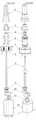
[도 1]의 (a)(b)는 본 발명 전동칫솔의 측면도와 정면도 이고 [도 2]에서 칫 솔(1)과 연결된 축(2)에 영구자석(9)이 철심(8)과 진동기코일(7) 중간에 장착되어 있다. 이러한 기구는 현재까지의 전동칫솔에는 없고 본 발명에서 최초로 적용실시 하였다. 현재까지의 전동칫솔에 있어서 칫솔의 운동방식은 [도 6]에서[도6-1]좌우운동과 [도6-2]상하운동 또는 [도6-3]스윙운동 등 단순운동으로만 되어 있다. 그 이유는 구동용 모터가 한 개 뿐이기 때문이다. [도6-4]는 본 발명의 칫솔동작그림으로 상하좌우로 운동함을 보여주고 있다. 대략 좌우운동의 칫솔모 운동폭은 1∼3mm사이고 운동속도는 5,000∼10,000 rpm사이이며 상하운동은 칫솔모 진폭이 대략 0.1∼1.0mm내외로 진동속도가 15,000∼35,000 stroke/min 으로 음파에 해당된다. 따라서 본 발명은 음파진동형 전동칫솔을 동시에 실현할 수 있게 한 발명인 것이다.(A) (b) of the present invention is a side view and a front view of the electric toothbrush of the present invention and the permanent magnet (9) on the shaft (2) connected to the toothbrush (1) in FIG. It is mounted in the middle of the
본 발명은 인간의 생존환경진화와 의학과 과학의 발달로 질병의 사전예방과 치유가 잘되어 생존기간이 연장되고 있으나 유독 "오복중의하나"라는 자연치아의 건강연장은 되지 않고 있어 노년이 되면 치아가 탈취되어 음식물을 씹을 수가 없기 때문에 소화도 나빠지고 맛도 음미할 수 없게 되어 불행한 생활을 하게 된다는 것에 착안하여 사망시간까지 건치를 유지 하게 하기위하여 치아의 건강과 구강의 위생을 가장 효과적으로 지킬 수 있는 칫솔을 연구 하게 되었고 그 결과 복합운동을 하는 칫솔이 가장 효과적이라는 결론에 도달하게 되었다. 이 과제를 해결하기 위하여서는 복합운동으로 칫솔질을 함이 가장 좋은데 손으로 닦는 일반 칫솔질로는 불 가능하고 오로지 전동칫솔 이어야 복합운동이 가능하기 때문에 연구의 결과로 본 발명을 하게 된 것이다.According to the present invention, the survival of human beings is improved, and the advancement of the disease is well prevented and cured due to the advancement of medicine and science. Since it is deodorized and cannot chew foods, it is difficult to digest and taste bad, so it is unfortunate to live an unhealthy life. To maintain dryness until the time of death, a toothbrush that can best protect the health of the teeth and the hygiene of the oral cavity is most effective. The study led to the conclusion that the combined exercise toothbrush was the most effective. In order to solve this problem, it is best to brush by compound movement, but general brushing by hand is impossible, and only the electric toothbrush is possible to perform complex movements.
본 발명은 일반적으로 과거의 기술로 되어있는 좌우운동방식의 충전지 내장 전동칫솔에 디지털 전자회로를 접목시키고 음파에 속하는 진동수를 가진 전자식진동기를 전동칫솔의 축에 장착시켜 좌우운동과 함께 연동하여 칫솔의 운동을 좌우와 상하 복합운동으로 동작하도록 발명한 것 이다.The present invention is a combination of a digital electronic circuit to the electric toothbrush built-in left and right movement method of the conventional technology of the past and the electronic vibrator having a frequency belonging to the sound wave is mounted on the axis of the electric toothbrush in conjunction with the left and right movement of the toothbrush The exercise was invented to operate in the left and right and up and down combined movement.
또한 디스프레이를 장착시켜 운동의 동작형태와 충전지의 충전방전 현황을 볼 수 있게 하였다. 이들 모든 동작의 명령과 수행은 MCU로 해결 하였다.In addition, the display is equipped with the movement of the movement and the charge and discharge status of the rechargeable battery can be seen. Command and execution of all these operations were solved by MCU.
본 발명은 치아의 장기보존을 위 하여서는 잇몸과 이빨과 이빨사이 즉 삼각델타구역을 얼마나 깨끗이 닦아내어 음식물 찌꺼기를 없게 하느냐가 기본 연구과제였다. 결과로는 이빨이 자리하고 있는 방향으로 아래위로 닦는 것이 치과의사들이 권장하는 가장 좋은 칫솔질이라는 기본 하에서 칫솔의 좌우운동방식을 선택 하였고 여기에 상하진동을 첨가하였기 때문에 가장 이상적이고 실효적인 칫솔질이라고 할 수 있다. 이와 같은 복합운동은 잇몸을 두들겨 잇몸 마사지효과를 동시에 가져오기 때문에 결과적으로 본 발명은 인간의 치아건강에 가장 적합한 효과를 이루게 하는 전동칫솔 이다.In the present invention, the long-term preservation of the tooth was how to wipe cleanly between the gums and teeth and teeth, that is, triangular delta area to eliminate food waste. The result is the most ideal and effective brushing because the brush is selected from the left and right movements and the upper and lower vibrations are added to the brush, which is the best brushing practice recommended by dentists. have. Since such a compound exercise is a result of pounding the gums at the same time as a gum massage effect, the present invention is an electric toothbrush that achieves the most suitable effect for human dental health.
본 발명을 첨부된 도면에 의하여 상세히 설명 하겠다.The present invention will be described in detail with reference to the accompanying drawings.
[도 1]에서 (a)는 본 전동칫솔의 측면도이고 (b)는 정면도 인데 몸체의 상부에 디스프레이가 설치되어 있고 두개의 스위치가 상하에 설치되어 있다.In Figure 1 (a) is a side view of the electric toothbrush (b) is a front view, the display is installed on the upper part of the body and two switches are installed above and below.
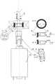
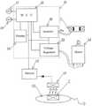
[도 2]는 내부 단면도 인데 교환용 칫솔(1)이 몸체(19)내부의 기구로부터 형성된 운동을 전달하는 축(2)에 삽입되어있다. 이 축(2)은 외부로부터 물의 유입을 차단하는 고무캡(4)과 프레임캡(3)에 끼워저서 중심 베어링(5)에 삽입되어 프레임(6)으로 고정되어있으며 또한 이 축(2)에는 상하진동 운동을 하게하는 전자식진동기의 진동자인 영구자석(9)이 고정자인 철심(8)과 진동기코일(7)의 가운데에 안치되어 있다. 또 이 축(2)의 끝단에는 좌우운동을 하게하는 캠(10)이 부착되어 있고 이 캠(10)은 모터(12)의 축에 삽입되어 있는 편심원통크랭크(11)에 의하여 모터(12)가 회전하면 크랭크(11)가 캠(10)을 자우로 운동시켜 즉 크랭크(11)와 캠(10)은 회전운동을 좌우왕복운동 으로 변환시켜 칫솔(1)을 좌우왕복으로 운동되게 한다. 따라서 축(2)에 삽입 설치 되어있는 진동자 영구자석(9)의 상하운동과 축(2)의 끝단에 안치되어있는 캠(10)의 좌우왕복운동이 결합되어 복합운동을 만들어 칫솔(1)에 전달하게 되는 것이다. 이들 두 가지 기구(진동기 및 모터)의 작동은 배터리(13)에 연결되어있는 전자회로 기판(16)에 의하여 지배된다. 충전식전원 배터리(13)는 무선충전 방식에 의하여 충전되며 몸체(19) 최하위 밑뚜껑(20)쪽에 설치되어 있는 충전용 수전코일(14)에 수전된 교류전류를 직류로 정류하여 충전된다. 본 발명의 동작원리를 더욱 상세히 설명 하기위하여 [도 3]과 [도 4]를 보자. [도 3]에서[도3-A]는 본 발명 전동칫솔내부의 프레임캡(3)에서부터 모터(12)까지의 부품전개단면도이고 [도3-B]는 이 전개된 부품들의 사시도 이다. 동작의 상세 설명을 위하여 [도 4]에서 축(2)에 영구자석(9)과 캠((10)이 동일 축위에 부착되어 있음을 볼수 있다. 여기서 진동기코일(7)에 인버터(22)로부터 교류전류가 인가되면 철심(8)이 (도-나)와 (도-다)처럼 N,S가 교번으로 자화(磁化)되고 이때 영구자석(9)은 교번자화하는 철심(8)의 자극에 따라 상하로 흡인 또는 반발을 하게 된다. 이때 진동기의 진동수는 진동기코일(7)에 흐르는 인버터(22)로부터 인가된 전류의 주파수로 결정되는데 이 주파수는 [도 5]에서 MCU(21)의 명령에 의하여 변환 결정된다. (도-가)는 철심(8)의 중심에 영구자석(9)이 어떤 자극(磁極)을 가지고 안치되어 있는지를 보여주는 도면이다. 또한 [도 4]에서 모터(12)의 축에 삽입 설치된 크랭크(11)는 캠(10)속에 들어가 있고 (도-라)에서처럼 편심원통 크랭크(11)가 회전하면 축(2)에 박혀있는 캠(10)은 좌우로 왕복운동을 하게 됨을 보여준다. 따라서 [도 4]에서 축(2)은 이들 두 기구에 의하여 상하좌우로 복합운동을 함을 알수 있고 이것이 본 발명이 현재의 전동칫솔과 다른 새로운 연구결과이다. 이들 두 기구(진동기와 모터)를 작동시키기 위하여 디지털 전자회로를 응용 적용하였다. [도 5]에서 전자회로기판(16)에는 MCU(21)를 중심으로 직류를 교류로 변환 시켜서 진동기코일(7)에 교번전류를 공급하는 인버터(22)와 모터의 속도를 조절하기위하여 직류전압을 조정 공급하는 전압레귤레이터(23)와 이러한 작동들을 시각으로 확인하도록 디스프레이(15)를 설치하였다. 이들의 구동 전원은 충전식 배터리(13)이며 이 배터리(13)는 충전용 수전코일(14)에 무선으로 수전된 교류전류를 다이오드가 정류하여 충전하게 되며 무선충전은 별도의 무선충전기(CH)의 내부에 있는 무선 송전코일(T)로부터 나오는 교류전자파(電磁波)를 수전코일(14)이 받아서 이루어지게 된다. 전자회 로를 작동시키기 위하여 두개의 버턴스위치를 설치하였는데 첫째 버턴스위치(SW1)(17)는 전체전원의 ON-OFF를 수행하지만 실제로는 누름의 횟수에 따라 ON-저속-중속-고속-마사지-OFF 등의 지정된 순서로 MCU(21)가 순환 동작을 모터(12)용 전압레귤레이터(23)에 명령하도록 하였고 또다른 버턴스위치(SW2)(18)는 전원이 ON된 상태 하에서 역시 누름의 횟수에 따라 인버터(22)의 교류 주파수를 변환시켜 고속 중속 저속 등으로 진동기의 진동수를 변환하게 하였다. 이러한 모든 동작과 배터리(13)의 충전 방전상태를 디지털 디스프레이(15)에 화면으로 볼수 있게 하였다. [도 6]에서 [도6-1][도6-2][도6-3]은 현재기술의 전동칫솔의 칫솔운동방향이고 [도6-4]는 본 발명의 칫솔 운동방향을 예시한 도면 이다.FIG. 2 is an internal sectional view in which a
[도6-1]은 좌우왕복운동 이고 [도6-2]는 상하왕복운동 이며 [도6-3]은 원형칫솔의 중심을 따라 스윙운동을 하는 등 단순운동을 보여주고 [도6-4]는 본 발명의 상하좌우운동을 하는 복합운동 방향도면 이다.[Figure 6-1] is a left and right reciprocating motion, [Figure 6-2] is a vertical reciprocation motion, and [Figure 6-3] shows a simple motion such as swinging along the center of a circular toothbrush. ] Is a composite motion direction drawing for the vertical movement of the left and right of the present invention.
[도 1]은 본 발명 전동칫솔 외형도1 is an external view of the present invention electric toothbrush
; (a)는 측면도 ; (a) is a side view
; (b)는 정면도 ; (b) front view
[도 2]는 본 발명 전동칫솔의 내부 단면도.2 is a cross-sectional view of the present invention powered toothbrush.
[도 3]은 본 발명 전동칫솔의 중요부품 전개도 {프레임캡(3)∼모터(12)}3 is an exploded view of important parts of the present invention electric toothbrush {
; [도3-A]는 전개된 중요부품의 단면도 ; 3-A is a cross-sectional view of the developed critical parts.
; [도3-B]는 전개된 중요부품의 사시도 ; 3-B is a perspective view of important parts deployed
[도 4]는 본 발명 전동칫솔의 복합운동을 설명하기위한 두 개의 구동기구만을 축(2)에 연결시켜 확대한 도면4 is an enlarged view by connecting only two drive mechanisms to the
; (도-가)는 영구자석(9)의 자극이 어떤형태로 착자(着磁)되어 철심(8)속에 안치되었는지를 보여주는 도면. ; (Fig.-A) is a diagram showing how the magnetic pole of the
; (도-나) (도-다)는 인버터로부터 교번전류가 인가되었을 때 영구자석(9)과 철심(8)이 흡인과반발 작용으로 상하로 진동함을 보여주는 도면 ; (Fig.-B) (Fig.-C) is a diagram showing that the
[도 5]는 본 발명 전동칫솔의 전자회로 불럭 연결도.5 is an electronic circuit block connection diagram of the present invention electric toothbrush.
; (GH)는 충전기 (T)는 충전기 내부의 전자파 발생 송전코일 ; (GH) is the charger (T) is electromagnetic wave transmission coil inside the charger
[도 6]은 본 발명 전동칫솔의 칫솔운동방향도[도6-4]와 현존하는 일반전동 칫솔의 칫솔운동방향도[도6-1][도6-2][도6-3].6 is a toothbrush movement direction diagram of the electric toothbrush of the present invention [Fig. 6-4] and a toothbrush movement direction diagram of the existing general electric toothbrush [Fig. 6-1] [Fig. 6-2] [Fig. 6-3].
Claims (2)
Translated fromKoreanPriority Applications (1)
| Application Number | Priority Date | Filing Date | Title |
|---|---|---|---|
| KR1020070133267AKR20090065779A (en) | 2007-12-18 | 2007-12-18 | Digital Compound Movement Electric Toothbrush |
Applications Claiming Priority (1)
| Application Number | Priority Date | Filing Date | Title |
|---|---|---|---|
| KR1020070133267AKR20090065779A (en) | 2007-12-18 | 2007-12-18 | Digital Compound Movement Electric Toothbrush |
Publications (1)
| Publication Number | Publication Date |
|---|---|
| KR20090065779Atrue KR20090065779A (en) | 2009-06-23 |
Family
ID=40993988
Family Applications (1)
| Application Number | Title | Priority Date | Filing Date |
|---|---|---|---|
| KR1020070133267ACeasedKR20090065779A (en) | 2007-12-18 | 2007-12-18 | Digital Compound Movement Electric Toothbrush |
Country Status (1)
| Country | Link |
|---|---|
| KR (1) | KR20090065779A (en) |
Cited By (3)
| Publication number | Priority date | Publication date | Assignee | Title |
|---|---|---|---|---|
| WO2018079913A1 (en)* | 2016-10-26 | 2018-05-03 | 주식회사 원스타인터내셔널 | Sound wave vibration toothbrush |
| CN112370198A (en)* | 2020-11-09 | 2021-02-19 | 北京紫涵科技有限公司 | Electric toothbrush based on voice prompt, toothbrush control method and storage medium |
| WO2021088282A1 (en)* | 2019-11-09 | 2021-05-14 | 郑云兵 | Hair washing brush |
- 2007
- 2007-12-18KRKR1020070133267Apatent/KR20090065779A/ennot_activeCeased
Cited By (5)
| Publication number | Priority date | Publication date | Assignee | Title |
|---|---|---|---|---|
| WO2018079913A1 (en)* | 2016-10-26 | 2018-05-03 | 주식회사 원스타인터내셔널 | Sound wave vibration toothbrush |
| US10888405B2 (en) | 2016-10-26 | 2021-01-12 | One Star International Co., Ltd. | Sonic vibration toothbrush |
| WO2021088282A1 (en)* | 2019-11-09 | 2021-05-14 | 郑云兵 | Hair washing brush |
| CN112370198A (en)* | 2020-11-09 | 2021-02-19 | 北京紫涵科技有限公司 | Electric toothbrush based on voice prompt, toothbrush control method and storage medium |
| CN112370198B (en)* | 2020-11-09 | 2022-03-08 | 北京紫涵科技有限公司 | Electric toothbrush based on voice prompt, toothbrush control method and storage medium |
Similar Documents
| Publication | Publication Date | Title |
|---|---|---|
| US5934908A (en) | High-powered automatic electromechanical toothbrush | |
| RU2389447C2 (en) | Electric tooth-brush | |
| US10166092B2 (en) | Toothbrush with a controlled transmission direction of vibration | |
| US20020092104A1 (en) | Acoustic toothbrush | |
| US20070244418A1 (en) | Vibrator sex toy conversion | |
| WO2011086960A1 (en) | Oral care device | |
| CN108601443A (en) | Electric toothbrush | |
| DE50015846D1 (en) | Oral care device with a vibrating interdental treatment head | |
| KR20050057480A (en) | Powered toothbrush | |
| CN101677847A (en) | The intraoral appliance that is used for cleaning teeth | |
| JP2018000942A (en) | Finger toothbrush for pet | |
| KR20190118778A (en) | Mouthpiece type of electric toothbrush | |
| JP2009045202A (en) | Electric toothbrush and replacement brush | |
| WO2020051434A1 (en) | Multiple mode dental device | |
| JP2008237276A (en) | Gum massaging equipment | |
| KR20090065779A (en) | Digital Compound Movement Electric Toothbrush | |
| KR100865731B1 (en) | Sonic vibration toothbrush | |
| KR101245713B1 (en) | The vibrating toothbrush with a function of turn-on by chewing | |
| KR101672239B1 (en) | Vibrating toothbrush | |
| CN201052193Y (en) | Electric tooth brush | |
| CN205126470U (en) | Electric toothbrush is sucked in oral cavity | |
| CN113892751B (en) | Novel toothbrush head and reciprocating type driven oral care device | |
| CN207768550U (en) | Electric toothbrush | |
| CN212015844U (en) | Portable buccal electric toothbrush capable of preventing mistaken swallowing | |
| CN1983777A (en) | Electric reciprocating moving unit |
Legal Events
| Date | Code | Title | Description |
|---|---|---|---|
| A201 | Request for examination | ||
| PA0109 | Patent application | Patent event code:PA01091R01D Comment text:Patent Application Patent event date:20071218 | |
| PA0201 | Request for examination | ||
| PG1501 | Laying open of application | ||
| E902 | Notification of reason for refusal | ||
| PE0902 | Notice of grounds for rejection | Comment text:Notification of reason for refusal Patent event date:20091030 Patent event code:PE09021S01D | |
| E601 | Decision to refuse application | ||
| PE0601 | Decision on rejection of patent | Patent event date:20100511 Comment text:Decision to Refuse Application Patent event code:PE06012S01D Patent event date:20091030 Comment text:Notification of reason for refusal Patent event code:PE06011S01I |