KR20090065778A - Double sided tape cutting method using laser - Google Patents
Double sided tape cutting method using laserDownload PDFInfo
- Publication number
- KR20090065778A KR20090065778AKR1020070133266AKR20070133266AKR20090065778AKR 20090065778 AKR20090065778 AKR 20090065778AKR 1020070133266 AKR1020070133266 AKR 1020070133266AKR 20070133266 AKR20070133266 AKR 20070133266AKR 20090065778 AKR20090065778 AKR 20090065778A
- Authority
- KR
- South Korea
- Prior art keywords
- laser
- cutting
- double
- sided tape
- paper
- Prior art date
- Legal status (The legal status is an assumption and is not a legal conclusion. Google has not performed a legal analysis and makes no representation as to the accuracy of the status listed.)
- Granted
Links
Images


Classifications
- B—PERFORMING OPERATIONS; TRANSPORTING
- B23—MACHINE TOOLS; METAL-WORKING NOT OTHERWISE PROVIDED FOR
- B23K—SOLDERING OR UNSOLDERING; WELDING; CLADDING OR PLATING BY SOLDERING OR WELDING; CUTTING BY APPLYING HEAT LOCALLY, e.g. FLAME CUTTING; WORKING BY LASER BEAM
- B23K26/00—Working by laser beam, e.g. welding, cutting or boring
- B23K26/36—Removing material
- B23K26/38—Removing material by boring or cutting
- B—PERFORMING OPERATIONS; TRANSPORTING
- B23—MACHINE TOOLS; METAL-WORKING NOT OTHERWISE PROVIDED FOR
- B23K—SOLDERING OR UNSOLDERING; WELDING; CLADDING OR PLATING BY SOLDERING OR WELDING; CUTTING BY APPLYING HEAT LOCALLY, e.g. FLAME CUTTING; WORKING BY LASER BEAM
- B23K26/00—Working by laser beam, e.g. welding, cutting or boring
- B23K26/08—Devices involving relative movement between laser beam and workpiece
- B23K26/0869—Devices involving movement of the laser head in at least one axial direction
- B23K26/0876—Devices involving movement of the laser head in at least one axial direction in at least two axial directions
- B—PERFORMING OPERATIONS; TRANSPORTING
- B23—MACHINE TOOLS; METAL-WORKING NOT OTHERWISE PROVIDED FOR
- B23Q—DETAILS, COMPONENTS, OR ACCESSORIES FOR MACHINE TOOLS, e.g. ARRANGEMENTS FOR COPYING OR CONTROLLING; MACHINE TOOLS IN GENERAL CHARACTERISED BY THE CONSTRUCTION OF PARTICULAR DETAILS OR COMPONENTS; COMBINATIONS OR ASSOCIATIONS OF METAL-WORKING MACHINES, NOT DIRECTED TO A PARTICULAR RESULT
- B23Q17/00—Arrangements for observing, indicating or measuring on machine tools
- B23Q17/24—Arrangements for observing, indicating or measuring on machine tools using optics or electromagnetic waves
- B—PERFORMING OPERATIONS; TRANSPORTING
- B26—HAND CUTTING TOOLS; CUTTING; SEVERING
- B26F—PERFORATING; PUNCHING; CUTTING-OUT; STAMPING-OUT; SEVERING BY MEANS OTHER THAN CUTTING
- B26F3/00—Severing by means other than cutting; Apparatus therefor
- B26F3/06—Severing by using heat
- B26F3/16—Severing by using heat by radiation
- H—ELECTRICITY
- H01—ELECTRIC ELEMENTS
- H01S—DEVICES USING THE PROCESS OF LIGHT AMPLIFICATION BY STIMULATED EMISSION OF RADIATION [LASER] TO AMPLIFY OR GENERATE LIGHT; DEVICES USING STIMULATED EMISSION OF ELECTROMAGNETIC RADIATION IN WAVE RANGES OTHER THAN OPTICAL
- H01S3/00—Lasers, i.e. devices using stimulated emission of electromagnetic radiation in the infrared, visible or ultraviolet wave range
- H01S3/005—Optical devices external to the laser cavity, specially adapted for lasers, e.g. for homogenisation of the beam or for manipulating laser pulses, e.g. pulse shaping
- H01S3/0085—Modulating the output, i.e. the laser beam is modulated outside the laser cavity
Landscapes
- Physics & Mathematics (AREA)
- Optics & Photonics (AREA)
- Engineering & Computer Science (AREA)
- Mechanical Engineering (AREA)
- Plasma & Fusion (AREA)
- Electromagnetism (AREA)
- Health & Medical Sciences (AREA)
- General Health & Medical Sciences (AREA)
- Toxicology (AREA)
- Life Sciences & Earth Sciences (AREA)
- Forests & Forestry (AREA)
- Laser Beam Processing (AREA)
Abstract
Translated fromKoreanDescription
Translated fromKorean본 발명은 레이저를 이용한 양면테이프 커팅방법에 관한 것으로서, 보다 상세하게는 레이저의 출력량 조절을 통해 양면테이프의 절단깊이를 용이하게 조절할 수 있는 레이저를 이용한 양면테이프 커팅방법이 제공된다.The present invention relates to a double-sided tape cutting method using a laser, and more particularly, to a double-sided tape cutting method using a laser that can easily adjust the cutting depth of the double-sided tape by adjusting the output amount of the laser.
일반적으로 투광성을 갖는 좌표입력장치인 터치패널은, CRT나 LCD(액정표시장치)의 표시면에 장착되어, 이 표시면을 눈으로 보면서 패널의 소정의 위치를 가압함으로써 여러 가지의 조작을 행하는 것이다.In general, a touch panel, which is a light transmissive coordinate input device, is mounted on a display surface of a CRT or LCD (liquid crystal display device), and performs various operations by pressing a predetermined position of the panel while visually viewing the display surface. .
첨부도면중 도 1은 종래의 터치패널을 나타내는 단면도로서, 저면에 상부전극(1a)이 형성된 필름(1)과, 상면에 하부전극(5a)이 형성된 투명한 합성수지 또는 유리등의 기판(5)과, 상기 하부전극(5a)의 상면에 인쇄하여 상부전극(1a)과 하부전극(5a)을 이격시키는 도트스페이서(4)로 되어 있고, 상기 필름(1)과 기판(5)은 테두리 부분에 있어서 틀 형상의 양면 접착지(3)에 의하여 서로 일체화되어 있다.1 is a cross-sectional view of a conventional touch panel, which includes a film 1 having an
상기 상부전극(1a)은 필름(1)의 저면에 ITO를 형성함으로써 구성되고, 하부전극(5a)은 유리기판(5)의 상면에 ITO를 형성함으로써 구성되며, 양면 접착지(3)는 상기 필름(1)과 기판(5)의 테두리에 개재하여 필름(1)과 기판(5)을 접착시키게 된다. 또한, 상기 도트스페이서(4)는 하부전극(2)의 윗면에 투명한 합성수지를 인쇄하여 반구형상으로 형성되는 것으로, 상부전극(1)의 아래면에 대향하고 있다. 또한, 기판(5)은 아크릴수지등의 투명한 합성수지 또는 유리등의 투명체로 이루어진 것이고, 가용성을 갖는 필름(1)은 양면 접착지(3)에 의하여 강도가 우수한 기판(5)상에 고정되어 있다.The
이와 같이 구성된 터치패널은, 사용할 경우에 LCD 등의 표시면의 앞면에 장착되어, 필름(1)의 임의의 위치를 펜이나 손가락 등으로 가압하면, 가압된 위치의 필름(1) 저면에 형성된 상부전극(1a)과 기판(5)상에 형성된 하부전극(5a)이 접촉하게 되면서 좌표를 검출시킬 수 있도록 되어 있다.The touch panel configured in this way is mounted on the front surface of a display surface such as an LCD when used, and when an arbitrary position of the film 1 is pressed with a pen or a finger, the upper portion formed on the bottom surface of the film 1 at the pressed position. The coordinates can be detected while the
종래 상기와 같이 기판(5)상에 필름(1)을 고정시키는 양면 접착지(3)를 테두리 형상으로 가공하기 위한 방법으로는 외주연에 박판커터를 구비한 한상의 커팅롤러 사이로 접착지의 상,하부에 이형지가 부착된 양면테이프를 통과시켜 양면테이프를 원하는 형상으로 절단하거나, 도 2와 같이 길이가 서로 다른 칼날(7a,7b)을 접착지(3)의 상,하부에 이형지(3a,3b)가 부착된 양면테이프의 상측으로부터 승강시키면서 절단하는 방법 등이 있다.Conventionally, in order to process the double-sided
그러나, 상기와 같은 종래의 커팅방법은 칼날을 이용하는 것이어서 절단 칼날의 마모에 따른 잦은 칼날교환의 불편함이 있다.However, the conventional cutting method as described above uses a blade, so there is an inconvenience of frequent blade replacement due to wear of the cutting blade.
또한, 절단시 칼날에 접착지의 접착성분이 쉽게 들러붙게 되는데, 절단 후 칼날이 양면테이프로부터 이탈하는 과정에서 접착지와 이형지가 칼날의 이동방향으 로 함께 이동하면서 들뜨게 되므로 정밀한 가공이 어려움은 물론, 절단 불량을 유발시키게 되며, 절단날의 마모에 따라 절단 깊이가 일정하지 않게 되는 경우 접착지가 완전하게 이탈되지 않게 되므로 생산수율이 저하되는 문제점이 발생된다.In addition, the adhesive component of the adhesive paper is easily adhered to the blade during cutting, and since the adhesive paper and the release paper move together in the moving direction of the blade in the process of detaching from the double-sided tape after cutting, it is difficult to precisely process, If the cutting depth is not constant according to the wear of the cutting blade is caused by the cutting failure, the adhesive paper is not completely separated, there is a problem that the production yield is lowered.
또한, 커팅 형상을 변경하고자 하는 경우에는 커팅장치를 분해하여 칼날의 배치를 바꾸거나, 칼날이 고정된 틀을 교환하여야 하는 불편함이 따르게 된다.In addition, if you want to change the shape of the cutting, disassembly the cutting device to change the arrangement of the blade, or the inconvenience of having to replace the fixed frame blade.
따라서, 본 발명의 목적은 이와 같은 종래의 문제점을 해결하기 위한 것으로서, 상,하부에 이형지가 부착된 양면테이프 원지로부터 소정의 절단깊이 및 형상으로 정밀하게 절단할 수 있는 레이저를 이용한 양면테이프 커팅방법을 제공함에 있다.Accordingly, an object of the present invention is to solve such a conventional problem, a double-sided tape cutting method using a laser that can be precisely cut to a predetermined cutting depth and shape from a double-sided tape paper with a release paper attached to the upper and lower parts. In providing.
상기 목적은, 본 발명에 따라, 접착지의 상,하부에 이형지가 부착되어 있는 양면테이프를 커팅하는 레이저를 이용한 양면테이프 커팅방법에 있어서, 작업용 테이블상에 양면테이프를 배치하는 단계;와, 레이저를 통해 테이블상의 양면테이프중 상부 이형지와 접착지만을 소정의 형상으로 절단하는 하프커팅단계; 및, 레이저를 통해 테이블상의 양면테이프의 상,하부 이형지와 접착지를 소정의 형상으로 절단하는 풀커팅단계;를 포함하는 레이저를 이용한 양면테이프 커팅방법에 의해 달성된다.The object is, according to the present invention, in the double-sided tape cutting method using a laser for cutting the double-sided tape is attached to the upper and lower portions of the adhesive paper, disposing the double-sided tape on the work table; and, laser Half cutting step of cutting only the upper release paper and the adhesive of the double-sided tape on the table to a predetermined shape through; And a full cutting step of cutting the upper and lower release paper and the adhesive paper of the double-sided tape on the table through a laser into a predetermined shape.
여기서, 상기 레이저는 CO2 레이저인 것이 바람직하다.Here, the laser is preferably a CO2 laser.
또한, 상기 하프커팅 단계는 상부이형지와 접착지만을 절단하는 정도의 수준으로 레이저 출력량을 설정하는 단계를 더 포함하는 것이 바람직하다.In addition, the half-cutting step preferably further comprises setting the laser output amount to the level of cutting only the upper release paper and the adhesive.
또한, 상기 풀커팅 단계는 상,하부 이형지와 접착지를 모두 절단하는 정도의 수준으로 레이저 출력량을 설정하는 단계를 더 포함하는 것이 바람직하다.In addition, the full cutting step preferably further comprises the step of setting the laser output amount to the level of cutting both the upper, lower release paper and the adhesive paper.
본 발명 레이저를 이용한 양면테이프 커팅방법의 상기 레이저는 레이저 발진부로부터 발생되어 레이저 헤드를 통해 양면테이프를 향해 공급되는 것으로, 상기 레이저 헤드의 내부에 스캐너(galvanometer)가 마련되어 레이저 반사각도를 조절함으로써 레이저 헤드가 소정 범위의 작업영역을 갖는 것이 바람직하다.The laser of the double-sided tape cutting method using the laser of the present invention is generated from the laser oscillation unit is supplied toward the double-sided tape through the laser head, a laser (galvanometer) is provided inside the laser head to adjust the laser reflection angle It is desirable to have a work area in a predetermined range.
또한, 상기 풀커팅 단계 수행 이후 상기 레이저 헤드의 작업영역내의 커팅이 완료되었는지 여부를 판단하는 단계를 더 포함하되, 레이저 헤드의 작업영역내 커팅이 완료되지 않은 경우 하프커팅 단계부터 다시 수행하는 것이 바람직하다.The method may further include determining whether the cutting in the working area of the laser head is completed after the full cutting step. If the cutting in the working area of the laser head is not completed, the half cutting step may be performed again. Do.
또한, 상기 레이저 헤드 작업영역내의 커팅이 완료되었는지 여부를 판단하는 단계 수행 이후 상기 양면테이프의 전 영역에 대한 커팅이 완료되었는지 여부를 판단하는 단계를 더 포함하되, 양면테이프 전 영역의 커팅이 완료되지 않은 경우 양면테이프의 커팅되지 않은 부위가 레이저 헤드의 작업영역에 위치하도록 테이블 또는 레이저 헤드를 이동시킨 뒤 하프커팅 단계부터 다시 수행하는 것이 바람직하다.The method may further include determining whether the cutting of the entire area of the double-sided tape is completed after performing the step of determining whether the cutting in the laser head working area is completed. If not, it is preferable to move the table or the laser head so that the uncut portion of the double-sided tape is located in the working area of the laser head, and then perform the half cutting step again.
본 발명에 따르면, 접착지의 상,하부에 이형지가 부착된 양면테이프를 절단함에 있어 상부 이형지와 접착지만을 절단하는 하프커팅과, 상,하부이형지 및 접착지를 모두 절단하는 풀커팅을 레이저의 출력량을 조절하여 수행함으로써 정밀한 깊이로 절단할 수 있으며, 테이블 또는 레이저 헤드를 X,Y축 방향으로 이동시키면서 양면테이프의 전 영역을 소정형상으로 절단하게 되므로 원하는 형상으로 정밀하게 절단할 수 있는 레이저를 이용한 양면테이프 커팅방법이 제공된다.According to the present invention, in cutting the double-sided tape with the release paper attached to the upper and lower portions of the adhesive paper, the half cutting for cutting the upper release paper and the adhesive, and the full cutting for cutting both the upper and lower release paper and the adhesive paper, the output of the laser. It can be cut to precise depth by adjusting it, and cutting the whole area of the double-sided tape in a predetermined shape while moving the table or laser head in the X, Y-axis direction. A tape cutting method is provided.
설명에 앞서, 여러 실시예에 있어서, 동일한 구성을 가지는 구성요소에 대해서는 동일한 부호를 사용하여 대표적으로 제1실시예에서 설명하고, 그 외의 실시예에서는 제1실시예와 다른 구성에 대해서 설명하기로 한다.Prior to the description, in the various embodiments, components having the same configuration will be representatively described in the first embodiment using the same reference numerals, and in other embodiments, different configurations from the first embodiment will be described. do.
이하, 첨부한 도면을 참조하여 본 발명의 제1실시예에 따른 레이저를 이용한 양면테이프 커팅방법에 대하여 상세하게 설명한다.Hereinafter, a double-sided tape cutting method using a laser according to a first embodiment of the present invention will be described in detail with reference to the accompanying drawings.
첨부도면중 도 3은 본 발명 레이저를 이용한 양면테이프 커팅방법에 따른 커팅시스템의 모식도이고, 도 4는 본 발명 레이저를 이용한 양면테이프 커팅방법의 순서도이다.3 is a schematic diagram of a cutting system according to a double-sided tape cutting method using a laser of the present invention, Figure 4 is a flow chart of a double-sided tape cutting method using a laser of the present invention.
상기 도 3에서 도시하는 바와 같이, 본 발명 레이저를 이용한 양면테이프 커팅방법에 따른 커팅시스템은 양면테이프(D)가 놓여지는 것으로 X,Y축 방향으로 이동하는 테이블(10)과, 상기 테이블(10)에 연결되어 테이블(10)상의 양면테이프(D)가 흡착되게 하는 진공펌프(12)와, CO₂레이저를 발생시키는 레이저 발진부(20)와, 상기 레이저 발진부(20)로부터 발생된 CO₂레이저를 양면테이프(D)를 향해 발사시키는 레이저 헤드(22)와, 상기 레이저 발진부(20)로부터 발생되는 CO₂레이저의 출력량을 설정하는 출력량 조절부(24) 및, 상기 레이저 헤드(22)에 고정되어 양면테이프(D)의 커팅부위로부터 영상을 획득하는 영상획득부(30)를 포함하여 구성된다. As shown in FIG. 3, the cutting system according to the double-sided tape cutting method using the laser of the present invention includes a table 10 moving in the X and Y-axis directions with the double-sided tape D placed thereon, and the table 10. Is connected to the
여기서, 상기 테이블(10)의 X,Y 축의 이동은 공지의 액츄에이터에 의해 이루어질 수 있다. 즉, 테이블(10)의 X,Y축 방향으로의 이동은 테이블(10)의 하면에 테이블(10)을 X축 방향으로 이동시키기 위한 리니어 모터 또는 볼스크류를 설치하고, 테이블(10) 하부의 테이블(10) 프레임에 상기 테이블(10)을 X축 방향으로 이동시키기 위한 리니어 모터 또는 볼스크류와 더불어 테이블(10)을 Y방향으로 이동시키기 위한 리니어 모터 또는 볼스크류가 설치되어 이루어질 수 있다. 여기에서 상기 테이블(10)의 X,Y축 방향으로의 이동을 위한 수단은 상술한 실시예에 의해 한정되지 않고 테이블(10)을 X,Y축 방향으로 이동시킬 수 있는 구조이면 어느 것이나 가능하다.Here, the movement of the X, Y axis of the table 10 may be made by a known actuator. That is, the movement of the table 10 in the X, Y axis direction is provided with a linear motor or a ball screw for moving the table 10 in the X axis direction on the lower surface of the table 10, In addition to the linear motor or ball screw for moving the table 10 in the X-axis direction, a linear motor or ball screw for moving the table 10 in the Y direction may be installed in the frame of the table 10. The means for moving the table 10 in the X and Y axis directions is not limited to the above-described embodiments, and any means may be used as long as the table 10 can be moved in the X and Y axis directions. .
한편, 본 실시예에서는 테이블(10)이 X,Y축 방향으로 이동하는 것으로 설명하였으나, 레이져 헤드(22)가 겐츄리타입의 이동수단에 설치되어 X,Y축 방향으로 이동하는 것도 가능할 것이다.Meanwhile, in the present embodiment, the table 10 is moved in the X and Y axis directions, but the
상기 레이저 헤드(22)는 스캐너(galvanometer)가 내장되어 메인 콘트롤러 및 스캐너 제어용 프로세서에 의해 레이저 반사각도를 조절함으로써 레이저 헤드(22)가 소정범위의 작업영역을 확보하게 된다.The
상기 영상획득부(30)에서 얻어지는 영상정보를 통해 레이저에 의한 양면테이프의 커팅상태를 자동으로 측정하고, 커팅후의 정밀도를 측정한다.The cutting state of the double-sided tape by the laser is automatically measured through the image information obtained by the
한편, 본 발명 레이저를 이용한 양면테이프 커팅방법은 도 4에서 도시하는 바와 같이 접착지(T)의 상,하부에 이형지(P1,P2)가 부착된 양면테이프(D)를 두께방향으로 전체 또는 일부분만 커팅하기 위한 것으로서, 크게 양면테이프(D)를 테이블(10)에 배치하고 진공펌프(12)를 가동시켜 테이블(10)에 양면테이프(D)를 흡착시키는 단계(S10)와, 양면테이프(D)의 커팅할 부분이 레이저 헤드(22)의 작업영역내 에 위치하도록 테이블(10) 또는 레이저 헤드(22)를 이동하는 단계(S20)와, 테이블(10)에 셋팅된 양면테이프(D)를 CO₂레이저를 이용하여 상부 이형지(P1)와 접착지(T)를 소정 형상으로 커팅하는 하프커팅단계(S30)와, 상,하부 이형지(P1,P2)와 접착지(T)를 소정 형상으로 커팅하는 풀커팅단계(S40)와, 레이저 헤드(22)의 작업영역내의 커팅이 완료되었는지를 판단하는 단계(S50)와, 양면테이프(D) 전 영역에 대한 커팅이 완료되었는지 여부를 판단하는 단계(S60)를 포함하여 구성된다.On the other hand, the double-sided tape cutting method using the laser of the present invention, as shown in Figure 4, the whole or part of the double-sided tape (D) having the release paper (P1, P2) attached to the upper and lower portions of the adhesive paper (T) in the thickness direction. In order to cut only, the step (S10) for placing the double-sided tape (D) on the table 10 and the
여기서, 상기 레이저 헤드(22)의 작업영역내의 커팅이 완료되었는지를 판단하는 단계(S50)에서는 레이저 헤드(22)의 작업영역내의 커팅이 완료되지 않은 경우 다시 하프커팅 단계(S30)로 이동하고, 레이저 헤드(22)의 작업영역내의 커팅이 완료된 경우 양면테이프 전 영역에 대한 커팅이 완료되었는지 여부를 판단하는 단계(S60)로 이동한다.Here, in the step S50 of determining whether the cutting in the working area of the
또한, 상기 양면테이프(D) 전 영역에 대한 커팅이 완료되었는지 여부를 판단하는 단계(S60)에서는 양면테이프(D) 전 영역의 커팅이 완료되지 않은 경우 양면테이프의 커팅할 부분이 레이저 헤드(22)의 작업영역내에 위치하도록 테이블(10)을 이동하는 단계(S20)로 이동하고, 양면테이프(D) 전 영역의 커팅이 완료된 경우 작업을 종료한다.In addition, in step S60 of determining whether the cutting of the entire area of the double-sided tape D is completed, when the cutting of the entire area of the double-sided tape D is not completed, the portion of the double-sided tape to be cut is the
상기 하프커팅단계(S30)는 상부이형지(P1)와 접착지(T)만을 절단하는 정도의 수준으로 CO₂레이저 출력량을 설정하는 단계(S31)와, 레이저 발진부(20)에서 설정된 출력량으로 CO₂레이저를 발생시키는 레이저 발생단계(S32)와, 상기 레이저 발진부(20)에서 발생된 CO₂레이저를 레이저 헤드(22)를 통해 테이블(10)상의 양면테 이프(D)로 발사하여 상부이형지(P1)와 접착지(T)를 절단하는 단계(S33)(도 5 참조)와, 상기와 같은 하프커팅이 완료되었는지 여부를 판단하는 단계(S34)로 이루어지며, 하프커팅이 완료되지 않은 경우 상기 레이저 발생단계(S32)로 이동하고, 완료된 경우 풀커팅단계(S40) 단계를 수행한다.The half cutting step (S30) is a step of setting the CO₂ laser output amount to a level of cutting only the upper release paper (P1) and the adhesive paper (T) (S31), and the CO₂ laser at the output amount set in the
상기 풀커팅단계(S40)는 상,하부이형지(P1,P2)와 접착지(T) 모두를 절단하는 정도의 수준으로 CO₂레이저 출력량을 설정하는 단계(S41)와, 레이저 발진부(20)에서 설정된 출력량으로 CO₂레이저를 발생시키는 레이저 발생단계(S42)와, 상기 CO₂레이저 발진부(20)에서 발생된 CO₂레이저를 레이저 헤드(22)를 통해 테이블(10)상의 양면테이프(D)로 발사하여 상,하부 이형지(P1,P2)와 접착지(T) 모두를 절단하는 단계(S43)(도 6 참조)와, 상기와 같은 풀커팅이 완료되었는지 여부를 판단하는 단계(S44)로 이루어지며, 풀커팅이 완료되지 않은 경우 상기 레이저 발생단계(S42)로 이동하고, 완료된 경우 레이저 헤드(22)의 작업영역내의 커팅이 완료되었는지를 판단하는 단계(S50)를 수행한다.The full cutting step (S40) is a step of setting the CO₂ laser output amount to the level of cutting both the upper and lower release paper (P1, P2) and the adhesive paper (T) (S41), and the
첨부도면중 도 7은 본 발명 레이저를 이용한 양면테이프 커팅방법을 통해 커팅된 양면테이프를 이용하여 터치패널의 유리기판과 필름을 접합시키는 방법을 나타낸 순서도이다.7 is a flowchart illustrating a method of bonding the glass substrate and the film of the touch panel using the double-sided tape cut by the double-sided tape cutting method using the laser of the present invention.
상술한 바와 같이 하프커팅단계(S20) 및 풀커팅단계(S30)를 통해 소정 형상으로 커팅이 이루어진 양면테이프(D)중 테두리 형상으로 절단된 테두리 접착지(T1)를 이용하여 터치패널의 기판과 필름을 접착시킬 수 있다.As described above, the substrate of the touch panel is formed by using the edge adhesive paper T1 cut in the shape of the edge of the double-sided tape D cut into the predetermined shape through the half cutting step S20 and the full cutting step S30. The film can be bonded.
이를 위해 상기 풀커팅단계(S40) 실시 후 상기 양면테이프(D)의 하부 이형지(P2)를 박리시켜 하프커팅된 중앙 접착지(T2)와 상기 중앙 접착지(T2)의 상측에 부착된 상부 이형지(P1)가 하부 이형지(P2)와 함께 박리되게 한 뒤, 테두리 접착지(T1)의 노출된 하부 접착면을 유리기판의 상면에 접착시키는 단계(S70)와, 상기 유리기판상에 접착된 테두리 접착지(T1)의 상부 이형지(P1)를 박리시키고 테두리 접착지(T1)의 노출된 상부 접착면에 필름을 접착시키는 단계(S80)를 수행한다.To this end, after the full cutting step (S40) is performed, the lower release paper P2 of the double-sided tape D is peeled off, and the upper release paper attached to an upper side of the half-cut central adhesive paper T2 and the central adhesive paper T2. After (P1) is peeled off with the lower release paper (P2), the step of adhering the exposed lower adhesive surface of the edge adhesive paper (T1) to the upper surface of the glass substrate (S70), the edge adhesive bonded on the glass substrate Peeling the upper release paper (P1) of the paper (T1) and performing a step (S80) of adhering the film to the exposed upper adhesive surface of the edge adhesive paper (T1).
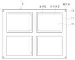
첨부도면중 도 8은 본 발명에 의해 하프커팅 및 풀커팅된 상태를 나타내는 양면테이프의 평면도이고, 도 9는 본 발명에 의해 커팅된 양면테이프의 분해사시도이다.8 is a plan view of a double-sided tape showing a half-cut and full-cut state in accordance with the present invention, Figure 9 is an exploded perspective view of a double-sided tape cut by the present invention.
상기 도 8에서 도시하는 바와 같이 양면테이프(D)는 각 모서리에 배치되는 위치정렬용 핀홀(T3)의 외곽선이 풀커팅되고, 터치패널의 크기에 따라 구획되는 테두리 접착지(T1)의 외곽선이 풀커팅되며, 상기 테두리 라인으로부터 내측으로 소정거리 이격된 위치에 터치패널의 표시영역에 해당하는 부위가 하프커팅되면서 접착지(T)가 테두리 접착지(T1)와 중앙 접착지(T2)로 구분된다.As shown in FIG. 8, the double-sided tape D has a full cut line of the alignment pinhole T3 disposed at each corner, and an outline of the edge adhesive paper T1 partitioned according to the size of the touch panel. The adhesive paper T is divided into the edge adhesive paper T1 and the center adhesive paper T2 while being fully cut and half-cutting a portion corresponding to the display area of the touch panel at a position spaced inwardly from the edge line. do.
상기와 같이 터치패널의 크기에 따라 풀커팅된 양면테이프(D)는 도 9에서와 같이 테두리 접착지(T1)와 동일한 형상을 갖는 상부이형지(P1)가 상측으로 박리되고, 테두리 접착지(T1)의 내측에서 하프커팅된 중앙 접착지(T2)와 상기 중앙 접착지(T2)의 상측에 부착된 상부이형지(P1)가 하부이형지(P2)와 함께 테두리 접착지(T1)로 부터 하측으로 박리된다.As described above, the double-sided tape D cut according to the size of the touch panel is peeled to the upper release paper P1 having the same shape as the edge adhesive paper T1 as shown in FIG. 9, and the edge adhesive paper T1. ) And the upper release paper (P1) attached to the upper side of the center adhesive paper (T2) half-cut from the inside of the peeled off from the edge adhesive paper (T1) together with the lower release paper (P2) do.
즉, 터치패널의 표시영역에 해당하는 중앙 접착지(T2)는 하프커팅되어 하부 이형지(P2)까지 절단되지 않았으므로, 상기 테두리 접착지(T1)로부터 하부이형지(P2)를 박리시키면 하부 이형지(P2)에 부착되어 있는 중앙 접착지(T2)와 상기 중앙 접착지(T2)의 상측에 부착된 상부 이형지(P1)가 하부 이형지(P2)와 함께 박리되면서 테두리 접착지(T1)와 상기 테두리 접착지(T1)의 상부에 부착된 상부 이형지(P1)가 남게 되며, 상기와 같은 테두리 접착지(T1)로부터 상부 이형지(P1)를 박리시키면 테두리 접착지(T1)의 상,하면 접착면이 노출되어 테두리 접착지(T1)의 상,하로 기판과 필름을 접착시킬 수 있게 된다.That is, since the center adhesive paper T2 corresponding to the display area of the touch panel is half cut and not cut to the lower release paper P2, the lower release paper P2 is peeled off from the edge adhesive paper T1. The center adhesive paper T2 attached to P2) and the upper release paper P1 attached to the upper side of the central adhesive paper T2 are peeled off together with the lower release paper P2, and the edge adhesive paper T1 and the edge adhesive The upper release paper P1 attached to the upper portion of the paper T1 remains, and when the upper release paper P1 is peeled from the edge adhesive paper T1 as described above, the upper and lower adhesive surfaces of the edge adhesive paper T1 are exposed. Thus, the substrate and the film may be adhered to the upper and lower edges of the edge adhesive paper T1.
상기와 같은 양면테이프(D)를 이용하여 기판과 필름을 접합하는 상태가 첨부도면 도 10에 나타나 있다.10 shows a state in which the substrate and the film are bonded by using the double-sided tape D as described above.
먼저, 도 10의 (a)에서와 같이 접착지(T)의 상,하부에 이형지(P1,P2)가 부착된 양면테이프(D)로부터 CO2 레이저를 통해 상,하부 이형지(P1,P2)와 접착지(T)가 모두 절단(풀커팅)된 부위(T')를 분리시킨 뒤, (b)와 같이 분리된 양면테이프(T')로부터 하부이형지(P2)를 박리시키면 상부이형지(P1)와 접착지(T)까지 CO2 레이저를 통해 절단(하프커팅)된 중앙 접착지(T2)가 하부이형지(P2)와 함께 이탈되면서 테두리 접착지(T1) 저면으로 접착면이 노출된다.First, as shown in (a) of FIG. 10, upper and lower release papers P1 and P2 through a CO2 laser from a double-sided tape D having release papers P1 and P2 attached to upper and lower portions of the adhesive paper T. And the adhesive paper (T) is cut (pull cut) the part (T ') after separating, and then peeled off the lower release paper (P2) from the separated double-sided tape (T') as shown in (b) the upper release paper (P1) ) And the adhesive sheet (T) is cut off (half-cut) through the CO2 laser with the lower release paper (P2) while the adhesive surface is exposed to the bottom of the edge adhesive paper (T1).
이어서 (c)와 같이 테두리 접착지(T1) 저면으로 기판(62)을 부착시킨 다음, 테두리 접착지(T1)의 상면에 부착된 상부이형지(P1)를 박리시켜 테두리 접착지(T1)의 상측으로 접착면이 노출되게 하고, (d)와 같이 상기 테두리 접착지(T1)의 상측 접착면으로 필름(64)을 부착시킨다.Subsequently, as shown in (c), the
따라서, 기판(62)과 필름(64)의 사이에 개재되는 테두리 접착지(T1)를 통해 기판(62)과 필름(64)이 접합되는 것이며, 테두리 접착지(T1)의 두께 만큼 서로 이격된 기판(62)과 필름(64)의 대향면에 각각 형성된 투명전극(미도시)이 외측으로부터 제공되는 가압력에 의해 접촉하면서 통전되어 터치패널의 기능을 수행하게 된다.Accordingly, the
상기한 바와 같은 본 발명 레이저를 이용한 양면테이프 커팅방법은 접착지(T)의 상,하부에 이형지(P1,P2)가 부착된 양면테이프(D)를 절단함에 있어 상부 이형지(P1)와 접착지(T)만을 절단하는 하프커팅과, 상,하부이형지(P1,P2) 및 접착지(T)를 절단하는 풀커팅을 CO₂레이저를 이용하여 수행함으로써 정밀한 절단이 가능하게 되므로 절단불량을 방지하고, 생산수율을 증가시킬 수 있게 된다.Double-sided tape cutting method using the laser of the present invention as described above, the upper release paper (P1) and the adhesive paper in cutting the double-sided tape (D) with the release paper (P1, P2) attached to the upper and lower portions of the adhesive paper (T) Half cutting to cut only (T), and full cutting to cut the upper and lower release paper (P1, P2) and adhesive paper (T) by using a CO₂ laser to enable precise cutting to prevent cutting defects, Production yields can be increased.
본 발명의 권리범위는 상술한 실시예에 한정되는 것이 아니라 첨부된 특허청구범위 내에서 다양한 형태의 실시예로 구현될 수 있다. 특허청구범위에서 청구하는 본 발명의 요지를 벗어남이 없이 당해 발명이 속하는 기술 분야에서 통상의 지식을 가진 자라면 누구든지 변형 가능한 다양한 범위까지 본 발명의 청구범위 기재의 범위 내에 있는 것으로 본다.The scope of the present invention is not limited to the above-described embodiment, but may be embodied in various forms of embodiments within the scope of the appended claims. Without departing from the gist of the invention claimed in the claims, it is intended that any person skilled in the art to which the present invention pertains falls within the scope of the claims described in the present invention to various extents which can be modified.
도 1은 종래의 터치패널을 나타내는 단면도1 is a cross-sectional view showing a conventional touch panel
도 2는 종래의 양면테이프를 절단하는 방법을 나타낸 단면도,Figure 2 is a cross-sectional view showing a method for cutting a conventional double-sided tape,
도 3은 본 발명 레이저를 이용한 양면테이프 커팅방법에 따른 커팅시스템의 모식도,Figure 3 is a schematic diagram of a cutting system according to the double-sided tape cutting method using the present invention laser,
도 4는 본 발명 레이저를 이용한 양면테이프 커팅방법의 순서도,4 is a flow chart of a double-sided tape cutting method using a laser of the present invention,
도 5는 본 발명 레이저를 이용한 양면테이프 커팅방법의 하프커팅상태를 나타낸 단면도,5 is a cross-sectional view showing a half cutting state of the double-sided tape cutting method using the laser of the present invention;
도 6은 본 발명 레이저를 이용한 양면테이프 커팅방법의 풀커팅상태를 나타낸 단면도,6 is a cross-sectional view showing a full cutting state of the double-sided tape cutting method using the laser of the present invention,
도 7은 본 발명에 의해 커팅된 양면테이프를 이용하여 터치패널의 유리기판과 필름을 접합시키는 방법을 나타낸 순서도,7 is a flowchart illustrating a method of bonding a glass substrate and a film of a touch panel using a double-sided tape cut according to the present invention;
도 8은 본 발명에 의해 하프커팅 및 풀커팅된 상태를 나타내는 양면테이프의 평면도,8 is a plan view of a double-sided tape showing the half-cut and full-cut state according to the present invention,
도 9는 본 발명에 의해 커팅된 양면테이프의 분해사시도,9 is an exploded perspective view of a double-sided tape cut by the present invention,
도 10은 본 발명에 의해 커팅된 양면테이프를 이용하여 기판과 필름을 접합하는 상태의 단면도이다.10 is a cross-sectional view of a state in which a substrate and a film are bonded by using a double-sided tape cut by the present invention.
Claims (7)
Translated fromKoreanPriority Applications (1)
| Application Number | Priority Date | Filing Date | Title |
|---|---|---|---|
| KR1020070133266AKR100962697B1 (en) | 2007-12-18 | 2007-12-18 | Double sided tape cutting method using laser |
Applications Claiming Priority (1)
| Application Number | Priority Date | Filing Date | Title |
|---|---|---|---|
| KR1020070133266AKR100962697B1 (en) | 2007-12-18 | 2007-12-18 | Double sided tape cutting method using laser |
Publications (2)
| Publication Number | Publication Date |
|---|---|
| KR20090065778Atrue KR20090065778A (en) | 2009-06-23 |
| KR100962697B1 KR100962697B1 (en) | 2010-06-11 |
Family
ID=40993987
Family Applications (1)
| Application Number | Title | Priority Date | Filing Date |
|---|---|---|---|
| KR1020070133266AExpired - Fee RelatedKR100962697B1 (en) | 2007-12-18 | 2007-12-18 | Double sided tape cutting method using laser |
Country Status (1)
| Country | Link |
|---|---|
| KR (1) | KR100962697B1 (en) |
Cited By (57)
| Publication number | Priority date | Publication date | Assignee | Title |
|---|---|---|---|---|
| WO2012053692A1 (en)* | 2010-10-20 | 2012-04-26 | 주식회사 딜리 | Label recovery coating device |
| KR20140066243A (en)* | 2011-09-21 | 2014-05-30 | 얼라인 테크널러지, 인크. | Laser cutting system and method of laser cutting |
| US10390913B2 (en) | 2018-01-26 | 2019-08-27 | Align Technology, Inc. | Diagnostic intraoral scanning |
| US10504386B2 (en) | 2015-01-27 | 2019-12-10 | Align Technology, Inc. | Training method and system for oral-cavity-imaging-and-modeling equipment |
| US10509838B2 (en) | 2016-07-27 | 2019-12-17 | Align Technology, Inc. | Methods and apparatuses for forming a three-dimensional volumetric model of a subject's teeth |
| US10517482B2 (en) | 2017-07-27 | 2019-12-31 | Align Technology, Inc. | Optical coherence tomography for orthodontic aligners |
| US10524881B2 (en) | 2010-04-30 | 2020-01-07 | Align Technology, Inc. | Patterned dental positioning appliance |
| US10537405B2 (en) | 2014-11-13 | 2020-01-21 | Align Technology, Inc. | Dental appliance with cavity for an unerupted or erupting tooth |
| US10543064B2 (en) | 2008-05-23 | 2020-01-28 | Align Technology, Inc. | Dental implant positioning |
| US10548700B2 (en) | 2016-12-16 | 2020-02-04 | Align Technology, Inc. | Dental appliance etch template |
| US10595966B2 (en) | 2016-11-04 | 2020-03-24 | Align Technology, Inc. | Methods and apparatuses for dental images |
| US10613515B2 (en) | 2017-03-31 | 2020-04-07 | Align Technology, Inc. | Orthodontic appliances including at least partially un-erupted teeth and method of forming them |
| US10610332B2 (en) | 2012-05-22 | 2020-04-07 | Align Technology, Inc. | Adjustment of tooth position in a virtual dental model |
| US10639134B2 (en) | 2017-06-26 | 2020-05-05 | Align Technology, Inc. | Biosensor performance indicator for intraoral appliances |
| US10758321B2 (en) | 2008-05-23 | 2020-09-01 | Align Technology, Inc. | Smile designer |
| US10779718B2 (en) | 2017-02-13 | 2020-09-22 | Align Technology, Inc. | Cheek retractor and mobile device holder |
| US10813720B2 (en) | 2017-10-05 | 2020-10-27 | Align Technology, Inc. | Interproximal reduction templates |
| US10842601B2 (en) | 2008-06-12 | 2020-11-24 | Align Technology, Inc. | Dental appliance |
| US10885521B2 (en) | 2017-07-17 | 2021-01-05 | Align Technology, Inc. | Method and apparatuses for interactive ordering of dental aligners |
| US10893918B2 (en) | 2012-03-01 | 2021-01-19 | Align Technology, Inc. | Determining a dental treatment difficulty |
| US10919209B2 (en) | 2009-08-13 | 2021-02-16 | Align Technology, Inc. | Method of forming a dental appliance |
| US10980613B2 (en) | 2017-12-29 | 2021-04-20 | Align Technology, Inc. | Augmented reality enhancements for dental practitioners |
| US10993783B2 (en) | 2016-12-02 | 2021-05-04 | Align Technology, Inc. | Methods and apparatuses for customizing a rapid palatal expander |
| US11026768B2 (en) | 1998-10-08 | 2021-06-08 | Align Technology, Inc. | Dental appliance reinforcement |
| US11026831B2 (en) | 2016-12-02 | 2021-06-08 | Align Technology, Inc. | Dental appliance features for speech enhancement |
| US11045283B2 (en) | 2017-06-09 | 2021-06-29 | Align Technology, Inc. | Palatal expander with skeletal anchorage devices |
| US11083545B2 (en) | 2009-03-19 | 2021-08-10 | Align Technology, Inc. | Dental wire attachment |
| US11096763B2 (en) | 2017-11-01 | 2021-08-24 | Align Technology, Inc. | Automatic treatment planning |
| US11103330B2 (en) | 2015-12-09 | 2021-08-31 | Align Technology, Inc. | Dental attachment placement structure |
| US11116605B2 (en) | 2017-08-15 | 2021-09-14 | Align Technology, Inc. | Buccal corridor assessment and computation |
| US11123156B2 (en) | 2017-08-17 | 2021-09-21 | Align Technology, Inc. | Dental appliance compliance monitoring |
| US11213368B2 (en) | 2008-03-25 | 2022-01-04 | Align Technology, Inc. | Reconstruction of non-visible part of tooth |
| US11219506B2 (en) | 2017-11-30 | 2022-01-11 | Align Technology, Inc. | Sensors for monitoring oral appliances |
| US11273011B2 (en) | 2016-12-02 | 2022-03-15 | Align Technology, Inc. | Palatal expanders and methods of expanding a palate |
| US11376101B2 (en) | 2016-12-02 | 2022-07-05 | Align Technology, Inc. | Force control, stop mechanism, regulating structure of removable arch adjustment appliance |
| US11419702B2 (en) | 2017-07-21 | 2022-08-23 | Align Technology, Inc. | Palatal contour anchorage |
| US11426259B2 (en) | 2012-02-02 | 2022-08-30 | Align Technology, Inc. | Identifying forces on a tooth |
| US11432908B2 (en) | 2017-12-15 | 2022-09-06 | Align Technology, Inc. | Closed loop adaptive orthodontic treatment methods and apparatuses |
| US11471252B2 (en) | 2008-10-08 | 2022-10-18 | Align Technology, Inc. | Dental positioning appliance having mesh portion |
| US11534974B2 (en) | 2017-11-17 | 2022-12-27 | Align Technology, Inc. | Customized fabrication of orthodontic retainers based on patient anatomy |
| US11534268B2 (en) | 2017-10-27 | 2022-12-27 | Align Technology, Inc. | Alternative bite adjustment structures |
| US11554000B2 (en) | 2015-11-12 | 2023-01-17 | Align Technology, Inc. | Dental attachment formation structure |
| US11564777B2 (en) | 2018-04-11 | 2023-01-31 | Align Technology, Inc. | Releasable palatal expanders |
| US11576752B2 (en) | 2017-10-31 | 2023-02-14 | Align Technology, Inc. | Dental appliance having selective occlusal loading and controlled intercuspation |
| US11596502B2 (en) | 2015-12-09 | 2023-03-07 | Align Technology, Inc. | Dental attachment placement structure |
| US11612454B2 (en) | 2010-04-30 | 2023-03-28 | Align Technology, Inc. | Individualized orthodontic treatment index |
| US11612455B2 (en) | 2016-06-17 | 2023-03-28 | Align Technology, Inc. | Orthodontic appliance performance monitor |
| US11633268B2 (en) | 2017-07-27 | 2023-04-25 | Align Technology, Inc. | Tooth shading, transparency and glazing |
| US11638629B2 (en) | 2014-09-19 | 2023-05-02 | Align Technology, Inc. | Arch expanding appliance |
| US11744677B2 (en) | 2014-09-19 | 2023-09-05 | Align Technology, Inc. | Arch adjustment appliance |
| US11931222B2 (en) | 2015-11-12 | 2024-03-19 | Align Technology, Inc. | Dental attachment formation structures |
| US11937991B2 (en) | 2018-03-27 | 2024-03-26 | Align Technology, Inc. | Dental attachment placement structure |
| US11996181B2 (en) | 2017-06-16 | 2024-05-28 | Align Technology, Inc. | Automatic detection of tooth type and eruption status |
| US12090020B2 (en) | 2017-03-27 | 2024-09-17 | Align Technology, Inc. | Apparatuses and methods assisting in dental therapies |
| US12171575B2 (en) | 2017-10-04 | 2024-12-24 | Align Technology, Inc. | Intraoral systems and methods for sampling soft-tissue |
| US12274597B2 (en) | 2017-08-11 | 2025-04-15 | Align Technology, Inc. | Dental attachment template tray systems |
| CN119973406A (en)* | 2025-03-19 | 2025-05-13 | 东莞艾塔极新材料科技有限公司 | OCA laser equipment and process |
- 2007
- 2007-12-18KRKR1020070133266Apatent/KR100962697B1/ennot_activeExpired - Fee Related
Cited By (69)
| Publication number | Priority date | Publication date | Assignee | Title |
|---|---|---|---|---|
| US11026768B2 (en) | 1998-10-08 | 2021-06-08 | Align Technology, Inc. | Dental appliance reinforcement |
| US11213368B2 (en) | 2008-03-25 | 2022-01-04 | Align Technology, Inc. | Reconstruction of non-visible part of tooth |
| US10758321B2 (en) | 2008-05-23 | 2020-09-01 | Align Technology, Inc. | Smile designer |
| US10543064B2 (en) | 2008-05-23 | 2020-01-28 | Align Technology, Inc. | Dental implant positioning |
| US10842601B2 (en) | 2008-06-12 | 2020-11-24 | Align Technology, Inc. | Dental appliance |
| US11471252B2 (en) | 2008-10-08 | 2022-10-18 | Align Technology, Inc. | Dental positioning appliance having mesh portion |
| US11083545B2 (en) | 2009-03-19 | 2021-08-10 | Align Technology, Inc. | Dental wire attachment |
| US10919209B2 (en) | 2009-08-13 | 2021-02-16 | Align Technology, Inc. | Method of forming a dental appliance |
| US10524881B2 (en) | 2010-04-30 | 2020-01-07 | Align Technology, Inc. | Patterned dental positioning appliance |
| US11612454B2 (en) | 2010-04-30 | 2023-03-28 | Align Technology, Inc. | Individualized orthodontic treatment index |
| WO2012053692A1 (en)* | 2010-10-20 | 2012-04-26 | 주식회사 딜리 | Label recovery coating device |
| KR20190026947A (en)* | 2011-09-21 | 2019-03-13 | 얼라인 테크널러지, 인크. | Laser cutting system and method of laser cutting |
| US10773337B2 (en) | 2011-09-21 | 2020-09-15 | Align Technology, Inc. | Laser cutting |
| KR20200024362A (en)* | 2011-09-21 | 2020-03-06 | 얼라인 테크널러지, 인크. | Laser cutting system and method of laser cutting |
| KR20140066243A (en)* | 2011-09-21 | 2014-05-30 | 얼라인 테크널러지, 인크. | Laser cutting system and method of laser cutting |
| US10195690B2 (en) | 2011-09-21 | 2019-02-05 | Align Technology, Inc. | Laser cutting |
| US10421152B2 (en) | 2011-09-21 | 2019-09-24 | Align Technology, Inc. | Laser cutting |
| US10828719B2 (en) | 2011-09-21 | 2020-11-10 | Align Technology, Inc. | Laser cutting |
| US11534861B2 (en) | 2011-09-21 | 2022-12-27 | Align Technology, Inc. | Laser cutting |
| KR20210016643A (en)* | 2011-09-21 | 2021-02-16 | 얼라인 테크널러지, 인크. | Laser cutting system and method of laser cutting |
| US11426259B2 (en) | 2012-02-02 | 2022-08-30 | Align Technology, Inc. | Identifying forces on a tooth |
| US10893918B2 (en) | 2012-03-01 | 2021-01-19 | Align Technology, Inc. | Determining a dental treatment difficulty |
| US10610332B2 (en) | 2012-05-22 | 2020-04-07 | Align Technology, Inc. | Adjustment of tooth position in a virtual dental model |
| US11638629B2 (en) | 2014-09-19 | 2023-05-02 | Align Technology, Inc. | Arch expanding appliance |
| US11744677B2 (en) | 2014-09-19 | 2023-09-05 | Align Technology, Inc. | Arch adjustment appliance |
| US10537405B2 (en) | 2014-11-13 | 2020-01-21 | Align Technology, Inc. | Dental appliance with cavity for an unerupted or erupting tooth |
| US10504386B2 (en) | 2015-01-27 | 2019-12-10 | Align Technology, Inc. | Training method and system for oral-cavity-imaging-and-modeling equipment |
| US11931222B2 (en) | 2015-11-12 | 2024-03-19 | Align Technology, Inc. | Dental attachment formation structures |
| US11554000B2 (en) | 2015-11-12 | 2023-01-17 | Align Technology, Inc. | Dental attachment formation structure |
| US11596502B2 (en) | 2015-12-09 | 2023-03-07 | Align Technology, Inc. | Dental attachment placement structure |
| US11103330B2 (en) | 2015-12-09 | 2021-08-31 | Align Technology, Inc. | Dental attachment placement structure |
| US11612455B2 (en) | 2016-06-17 | 2023-03-28 | Align Technology, Inc. | Orthodontic appliance performance monitor |
| US10606911B2 (en) | 2016-07-27 | 2020-03-31 | Align Technology, Inc. | Intraoral scanner with dental diagnostics capabilities |
| US10585958B2 (en) | 2016-07-27 | 2020-03-10 | Align Technology, Inc. | Intraoral scanner with dental diagnostics capabilities |
| US10509838B2 (en) | 2016-07-27 | 2019-12-17 | Align Technology, Inc. | Methods and apparatuses for forming a three-dimensional volumetric model of a subject's teeth |
| US10595966B2 (en) | 2016-11-04 | 2020-03-24 | Align Technology, Inc. | Methods and apparatuses for dental images |
| US11026831B2 (en) | 2016-12-02 | 2021-06-08 | Align Technology, Inc. | Dental appliance features for speech enhancement |
| US10993783B2 (en) | 2016-12-02 | 2021-05-04 | Align Technology, Inc. | Methods and apparatuses for customizing a rapid palatal expander |
| US11273011B2 (en) | 2016-12-02 | 2022-03-15 | Align Technology, Inc. | Palatal expanders and methods of expanding a palate |
| US11376101B2 (en) | 2016-12-02 | 2022-07-05 | Align Technology, Inc. | Force control, stop mechanism, regulating structure of removable arch adjustment appliance |
| US10548700B2 (en) | 2016-12-16 | 2020-02-04 | Align Technology, Inc. | Dental appliance etch template |
| US10779718B2 (en) | 2017-02-13 | 2020-09-22 | Align Technology, Inc. | Cheek retractor and mobile device holder |
| US12090020B2 (en) | 2017-03-27 | 2024-09-17 | Align Technology, Inc. | Apparatuses and methods assisting in dental therapies |
| US10613515B2 (en) | 2017-03-31 | 2020-04-07 | Align Technology, Inc. | Orthodontic appliances including at least partially un-erupted teeth and method of forming them |
| US11045283B2 (en) | 2017-06-09 | 2021-06-29 | Align Technology, Inc. | Palatal expander with skeletal anchorage devices |
| US11996181B2 (en) | 2017-06-16 | 2024-05-28 | Align Technology, Inc. | Automatic detection of tooth type and eruption status |
| US10639134B2 (en) | 2017-06-26 | 2020-05-05 | Align Technology, Inc. | Biosensor performance indicator for intraoral appliances |
| US10885521B2 (en) | 2017-07-17 | 2021-01-05 | Align Technology, Inc. | Method and apparatuses for interactive ordering of dental aligners |
| US11419702B2 (en) | 2017-07-21 | 2022-08-23 | Align Technology, Inc. | Palatal contour anchorage |
| US10517482B2 (en) | 2017-07-27 | 2019-12-31 | Align Technology, Inc. | Optical coherence tomography for orthodontic aligners |
| US11633268B2 (en) | 2017-07-27 | 2023-04-25 | Align Technology, Inc. | Tooth shading, transparency and glazing |
| US12274597B2 (en) | 2017-08-11 | 2025-04-15 | Align Technology, Inc. | Dental attachment template tray systems |
| US11116605B2 (en) | 2017-08-15 | 2021-09-14 | Align Technology, Inc. | Buccal corridor assessment and computation |
| US11123156B2 (en) | 2017-08-17 | 2021-09-21 | Align Technology, Inc. | Dental appliance compliance monitoring |
| US12171575B2 (en) | 2017-10-04 | 2024-12-24 | Align Technology, Inc. | Intraoral systems and methods for sampling soft-tissue |
| US10813720B2 (en) | 2017-10-05 | 2020-10-27 | Align Technology, Inc. | Interproximal reduction templates |
| US11534268B2 (en) | 2017-10-27 | 2022-12-27 | Align Technology, Inc. | Alternative bite adjustment structures |
| US11576752B2 (en) | 2017-10-31 | 2023-02-14 | Align Technology, Inc. | Dental appliance having selective occlusal loading and controlled intercuspation |
| US11096763B2 (en) | 2017-11-01 | 2021-08-24 | Align Technology, Inc. | Automatic treatment planning |
| US11534974B2 (en) | 2017-11-17 | 2022-12-27 | Align Technology, Inc. | Customized fabrication of orthodontic retainers based on patient anatomy |
| US11219506B2 (en) | 2017-11-30 | 2022-01-11 | Align Technology, Inc. | Sensors for monitoring oral appliances |
| US11432908B2 (en) | 2017-12-15 | 2022-09-06 | Align Technology, Inc. | Closed loop adaptive orthodontic treatment methods and apparatuses |
| US10980613B2 (en) | 2017-12-29 | 2021-04-20 | Align Technology, Inc. | Augmented reality enhancements for dental practitioners |
| US10390913B2 (en) | 2018-01-26 | 2019-08-27 | Align Technology, Inc. | Diagnostic intraoral scanning |
| US11013581B2 (en) | 2018-01-26 | 2021-05-25 | Align Technology, Inc. | Diagnostic intraoral methods and apparatuses |
| US10813727B2 (en) | 2018-01-26 | 2020-10-27 | Align Technology, Inc. | Diagnostic intraoral tracking |
| US11937991B2 (en) | 2018-03-27 | 2024-03-26 | Align Technology, Inc. | Dental attachment placement structure |
| US11564777B2 (en) | 2018-04-11 | 2023-01-31 | Align Technology, Inc. | Releasable palatal expanders |
| CN119973406A (en)* | 2025-03-19 | 2025-05-13 | 东莞艾塔极新材料科技有限公司 | OCA laser equipment and process |
Also Published As
| Publication number | Publication date |
|---|---|
| KR100962697B1 (en) | 2010-06-11 |
Similar Documents
| Publication | Publication Date | Title |
|---|---|---|
| KR100962697B1 (en) | Double sided tape cutting method using laser | |
| KR101788198B1 (en) | Lamination apparatus and lamination method using the same | |
| CN107340943B (en) | Capacitive touch screen and laminating method thereof | |
| CN104049407A (en) | Methods for Trimming Display Polarizers Using Lasers | |
| JP6375564B2 (en) | Manufacturing method of laminate | |
| KR101606331B1 (en) | Methods and equipment for trimming polarizers in displays | |
| JP2012221925A (en) | Assembly jig | |
| CN104881191A (en) | Large-size capacitance and electromagnetism integrated touch device | |
| CN103852928A (en) | Lamination Systems With Temperature-Controlled Lamination Rollers | |
| WO2018094613A1 (en) | Pressure detection apparatus, touch control screen and touch control terminal | |
| JP2006292993A (en) | Bonding device | |
| KR20210152162A (en) | Tape cutting device and method using laser | |
| KR101581503B1 (en) | Methods for trimming polarizers in displays | |
| US11515371B2 (en) | Display device with fingerprint recognition sensor and manufacturing method thereof | |
| KR101216613B1 (en) | Plastic cover window coated with glass for touch screen panel and its manufacturing method | |
| CN109940868A (en) | An automatic display equipment display protective film laminating machine | |
| KR101850652B1 (en) | Industrial touch screen panel and manufacturing method | |
| CN201913867U (en) | Position device used during jointing of touch screen | |
| CN203689476U (en) | Touch screen | |
| KR20200121040A (en) | Apparatus for cutting decoration board and method for manufacturing decoration board using the same | |
| JP6611431B2 (en) | Application method and film | |
| US20200316844A1 (en) | Embossing apparatus and embossing method | |
| CN207992980U (en) | A kind of touch screen for Wearable | |
| US9703139B2 (en) | Methods for trimming polarizers in displays | |
| TWI702580B (en) | Display device and manufacturing method thereof |
Legal Events
| Date | Code | Title | Description |
|---|---|---|---|
| A201 | Request for examination | ||
| PA0109 | Patent application | St.27 status event code:A-0-1-A10-A12-nap-PA0109 | |
| PA0201 | Request for examination | St.27 status event code:A-1-2-D10-D11-exm-PA0201 | |
| D13-X000 | Search requested | St.27 status event code:A-1-2-D10-D13-srh-X000 | |
| D14-X000 | Search report completed | St.27 status event code:A-1-2-D10-D14-srh-X000 | |
| PG1501 | Laying open of application | St.27 status event code:A-1-1-Q10-Q12-nap-PG1501 | |
| E902 | Notification of reason for refusal | ||
| PE0902 | Notice of grounds for rejection | St.27 status event code:A-1-2-D10-D21-exm-PE0902 | |
| T11-X000 | Administrative time limit extension requested | St.27 status event code:U-3-3-T10-T11-oth-X000 | |
| E13-X000 | Pre-grant limitation requested | St.27 status event code:A-2-3-E10-E13-lim-X000 | |
| P11-X000 | Amendment of application requested | St.27 status event code:A-2-2-P10-P11-nap-X000 | |
| P13-X000 | Application amended | St.27 status event code:A-2-2-P10-P13-nap-X000 | |
| R17-X000 | Change to representative recorded | St.27 status event code:A-3-3-R10-R17-oth-X000 | |
| E701 | Decision to grant or registration of patent right | ||
| PE0701 | Decision of registration | St.27 status event code:A-1-2-D10-D22-exm-PE0701 | |
| R17-X000 | Change to representative recorded | St.27 status event code:A-3-3-R10-R17-oth-X000 | |
| GRNT | Written decision to grant | ||
| PR0701 | Registration of establishment | St.27 status event code:A-2-4-F10-F11-exm-PR0701 | |
| PR1002 | Payment of registration fee | St.27 status event code:A-2-2-U10-U11-oth-PR1002 Fee payment year number:1 | |
| PG1601 | Publication of registration | St.27 status event code:A-4-4-Q10-Q13-nap-PG1601 | |
| PN2301 | Change of applicant | St.27 status event code:A-5-5-R10-R13-asn-PN2301 St.27 status event code:A-5-5-R10-R11-asn-PN2301 | |
| FPAY | Annual fee payment | Payment date:20130523 Year of fee payment:4 | |
| PR1001 | Payment of annual fee | St.27 status event code:A-4-4-U10-U11-oth-PR1001 Fee payment year number:4 | |
| P22-X000 | Classification modified | St.27 status event code:A-4-4-P10-P22-nap-X000 | |
| LAPS | Lapse due to unpaid annual fee | ||
| PC1903 | Unpaid annual fee | St.27 status event code:A-4-4-U10-U13-oth-PC1903 Not in force date:20140604 Payment event data comment text:Termination Category : DEFAULT_OF_REGISTRATION_FEE | |
| PN2301 | Change of applicant | St.27 status event code:A-5-5-R10-R13-asn-PN2301 St.27 status event code:A-5-5-R10-R11-asn-PN2301 | |
| PC1903 | Unpaid annual fee | St.27 status event code:N-4-6-H10-H13-oth-PC1903 Ip right cessation event data comment text:Termination Category : DEFAULT_OF_REGISTRATION_FEE Not in force date:20140604 | |
| P22-X000 | Classification modified | St.27 status event code:A-4-4-P10-P22-nap-X000 | |
| R18-X000 | Changes to party contact information recorded | St.27 status event code:A-5-5-R10-R18-oth-X000 |