KR20090065077A - Artificial teeth - Google Patents
Artificial teethDownload PDFInfo
- Publication number
- KR20090065077A KR20090065077AKR1020070132514AKR20070132514AKR20090065077AKR 20090065077 AKR20090065077 AKR 20090065077AKR 1020070132514 AKR1020070132514 AKR 1020070132514AKR 20070132514 AKR20070132514 AKR 20070132514AKR 20090065077 AKR20090065077 AKR 20090065077A
- Authority
- KR
- South Korea
- Prior art keywords
- body portion
- bone
- artificial tooth
- upper body
- protrusion
- Prior art date
- Legal status (The legal status is an assumption and is not a legal conclusion. Google has not performed a legal analysis and makes no representation as to the accuracy of the status listed.)
- Granted
Links
Images


Classifications
- A—HUMAN NECESSITIES
- A61—MEDICAL OR VETERINARY SCIENCE; HYGIENE
- A61C—DENTISTRY; APPARATUS OR METHODS FOR ORAL OR DENTAL HYGIENE
- A61C8/00—Means to be fixed to the jaw-bone for consolidating natural teeth or for fixing dental prostheses thereon; Dental implants; Implanting tools
- A61C8/0018—Means to be fixed to the jaw-bone for consolidating natural teeth or for fixing dental prostheses thereon; Dental implants; Implanting tools characterised by the shape
- A61C8/0022—Self-screwing
- A61C8/0025—Self-screwing with multiple threads
- A—HUMAN NECESSITIES
- A61—MEDICAL OR VETERINARY SCIENCE; HYGIENE
- A61C—DENTISTRY; APPARATUS OR METHODS FOR ORAL OR DENTAL HYGIENE
- A61C8/00—Means to be fixed to the jaw-bone for consolidating natural teeth or for fixing dental prostheses thereon; Dental implants; Implanting tools
- A61C8/0018—Means to be fixed to the jaw-bone for consolidating natural teeth or for fixing dental prostheses thereon; Dental implants; Implanting tools characterised by the shape
- A61C8/0037—Details of the shape
- A61C2008/0046—Textured surface, e.g. roughness, microstructure
Landscapes
- Health & Medical Sciences (AREA)
- Oral & Maxillofacial Surgery (AREA)
- Orthopedic Medicine & Surgery (AREA)
- Dentistry (AREA)
- Epidemiology (AREA)
- Life Sciences & Earth Sciences (AREA)
- Animal Behavior & Ethology (AREA)
- General Health & Medical Sciences (AREA)
- Public Health (AREA)
- Veterinary Medicine (AREA)
- Dental Prosthetics (AREA)
Abstract
Translated fromKoreanDescription
Translated fromKorean본 발명은 치조골에 식립되는 인공치아의 항상성이 유지되도록 전단응력을 상부에서 감소시키고 응력을 분산시켜 치조골의 침하를 방지할 수 있는 인공치아에 관한 것으로, 보다 상세하게는 본 발명의 인공치아는 상단 몸통부부와 하단 몸통부를 포함하는데, 상기 상단몸통부의 함몰부에서의 직경이 상기 하단몸통부의 함몰부에서의 직경에 비해 더 크도록 함으로써 골압축량을 조절하여 전단응력이 상단몸통부에 집중할 수 있는 것을 하단몸통부로 응력을 분산시킬 수 있는 효과를 도모하고 식립토크의 점진적 증가에 따른 초기고정력 확보의 효과를 도모하고 이로써 치조골의 침하를 방지하고, 안정된 인공치아의 시술을 이룰 수 있도록 하는 인공치아에 관한 것이다. 또한, 본 발명의 인공치아는 돌출부와 돌출부 간의 거리가 일정하도록 유지하여 상기 돌출부가 나사 프로파일로 이루어지는 경우 동일한 리드를 갖도록 함으로써 식립시 치조골의 손상을 최소화할 수 있도록 할 수 있고, 상단 몸통부의 골지름이 확장됨에 따라 골의 표면이 넓어질 수 있는데, 이러한 넓어진 표면에 오목부를 포함하도록 하여 치조골과의 접촉력을 더욱 향상시킬 수 있게 된다.The present invention relates to an artificial tooth which can prevent the subsidence of the alveolar bone by reducing the shear stress at the top and dispersing the stress so that the homeostasis of the artificial tooth placed in the alveolar bone is maintained. It includes a body portion and a lower body portion, by adjusting the bone compression amount by making the diameter at the depression of the upper body portion larger than the diameter at the depression of the lower body portion can shear stress can concentrate on the upper body portion The artificial tooth is designed to spread the stress to the lower body and to secure the initial fixation force by the gradual increase of the insertion torque, thereby preventing the subsidence of the alveolar bone and achieving a stable artificial tooth treatment. It is about. In addition, the artificial tooth of the present invention can maintain a constant distance between the protrusion and the protrusion to have the same lead when the protrusion is made of a screw profile to minimize damage to the alveolar bone during implantation, the rib diameter of the upper body As this is expanded, the surface of the bone can be widened, and by including the recessed portion in the widened surface, the contact force with the alveolar bone can be further improved.
인공치아인 임플란트는 원래 인체조직이 상실되었을 때 회복시켜 주는 대치물을 의미하지만 치과에서는 인공으로 만든 치아를 이식하는 것을 말한다. 상실된 치아의 치근(뿌리)를 대신할 수 있도록 인체에 거부반응이 없는 티타늄(Titanium) 등으로 만든 치근을 이가 빠져나간 뼈에 심은 뒤 인공치아를 고정시켜 치아의 기능을 회복하도록 하는 첨단시술이다. 일반 보철물이나 틀니의 경우 시간이 지나면 주위 치아와 뼈가 상하지만 임플란트는 주변 치아조직을 상하지 않게 하며, 자연치아와 기능이나 모양이 같으면서도 충치가 생기지 않으므로 반영구적으로 사용할 수 있는 장점이 있다. 이와 같은 치과용 임플란트에는 스크류타입의 픽스츄어가 사용되는데, 상기 픽스츄어 몸통부 외주면에 나사산이 형성되어 있으며, 치과 및 정형외과의 보철물 등을 뼈에 고정하기 위한 고정부재로서 사용된다. 의학기술의 발달과 시술능력의 향상에 힘입어, 현대에는 인공치아의 성공률 향상에 따라 인공치아 시술은 보편화 되어지고 시술의 편의성이 대두되어져 가고 있다.Implants, which are artificial teeth, originally meant a substitute to recover when human tissue was lost, but dental implants refer to implanting artificial teeth. It is a cutting-edge procedure that restores the function of teeth by fixing the artificial tooth after planting the tooth root made of titanium (Titanium) without rejection in the human body to replace the root of the lost tooth (root). In the case of general prosthetics or dentures, the surrounding teeth and bones are damaged after time, but the implants do not damage the surrounding dental tissues, and they have the advantage that they can be used semi-permanently because they have the same function or shape as natural teeth and do not cause tooth decay. Screw type fixtures are used for such dental implants, and threads are formed on the outer circumferential surface of the fixture body, and are used as fixing members for fixing prosthetics of dental and orthopedics to bones. With the development of medical technology and the improvement of the treatment ability, the artificial tooth treatment is becoming more common and the convenience of the procedure is increasing as the success rate of the artificial tooth is improved in modern times.
이에 기존의 인공치아는 원통형 축에 외부에 나사산이 형성되어 있고, 외부 또는 내부에 보철물과의 연결부를 가지고 있다. 인공치아의 원통형 외부의 나사산은 인공치아를 식립할 때 편의성을 제공하고, 또한 골융합 이후에는 치조골로의 적절한 응력분산을 통해 치조골을 유지시키는 기능을 갖게 된다. 원통형 외부에 형성되어 있는 나사산은 도 1에 도시된 바와 같이 상단부와 하단부가 동일한 형태로 구성되는 형태와 도 2에 도시된 바와 같이 하단부에는 큰나사산이 상단부에는 작은나사산이 구성되어 있는 형태로 크게 구분된다.The existing artificial teeth have a thread formed on the outside of the cylindrical shaft, and has a connection with the prosthesis on the outside or inside. The thread outside the cylindrical shape of the artificial tooth provides convenience when placing the artificial tooth and also has the function of maintaining the alveolar bone through proper stress distribution to the alveolar bone after bone fusion. The screw thread formed on the cylindrical outer side is divided into a form in which the upper end and the lower end are configured in the same shape as shown in FIG. 1, and a large screw mountain at the lower end and a small screw mountain at the upper end as shown in FIG. 2. do.
종래의 나사산이 동일한 형태로 구성 되어지는 인공치아(도 1)는 식립시 편의성은 우수하나 골유착 후에 응력분산효과가 떨어져서 안정된 치조골의 유지에 불리하고, 하단부에 큰 나사산과 상단에 작은나사산으로 구성되어 있는 형태(도 2)는 응력분산효과에서는 유리하나 이러한 응력분산의 효과는 단지 접촉면적의 차이를 변화시킴으로써 응력이 분산될 수 있도록 하는 것에 불과하다. 따라서, 전단응력의 경우 동일한 나사골에 따른 응력 분산의 효과를 적절하게 달성할 수 없게 된다. 따라서 전단응력의 집중에 따른 종래의 인공치아가 식립된 경우 치조골과 완벽하게 일체화되지 못하고, 치조골의 침하를 방지할 수 없게 되며, 심한 경우에는 상기 인공치아가 치조골로부터 이탈되어 빠지게 되는 심각한 결과를 초래하기도 한다.Artificial teeth (FIG. 1), which are conventionally composed of the same thread, have excellent convenience in implantation but have a stress dispersing effect after bone adhesion, which is disadvantageous for maintaining stable alveolar bone, and consists of a large thread at the bottom and a small screw at the top. 2 is advantageous in the stress dispersion effect, but the effect of the stress dispersion is merely to allow the stress to be dispersed by changing the difference in the contact area. Therefore, in the case of shear stress, the effect of stress dispersion along the same screw bone cannot be properly achieved. Therefore, when a conventional artificial tooth is implanted due to the concentration of shear stress, the alveolar bone may not be perfectly integrated, and the subsidence of the alveolar bone may not be prevented. Sometimes.
또한, 기존의 균일한 돌출부를 가진 인공치아(도 1)는 반복회전에 의해 식립시 나타나는 토크양상이 초기 상승 후 점점 감소하는 경향을 보이게 되며 초기고정력이 낮고, 하단부 큰 나사산과 상단 작은 나사산으로 구성된 인공치아(도 2)는 작은 나사산이 식립될 때 급격한 토크상승에 의해 식립이 되어지지 않는 단점이 있다. 이에 상기 종래 인공치아에서의 문제점을 해결하기 위하여 하단에서 상단의 치조골과의 접촉면적 상승이 적어서 급격한 토크의 상승을 방지할 수 있도록 하고, 식립토크가 점진적으로 증가하여 적절한 초기고정력을 확보할 수 있도록 하는 인공치아의 필요성이 대두되고 있다.In addition, the existing teeth having a uniform protrusion (Fig. 1) shows a tendency to decrease gradually after the initial rise of the torque pattern appearing in the repetitive rotation, the initial fixing force is low, consisting of a large thread at the bottom and a small thread at the top Artificial teeth (FIG. 2) have a disadvantage in that they are not placed by rapid torque rise when a small thread is placed. In order to solve the problems in the conventional artificial teeth, the contact area with the alveolar bone at the lower end is less increased to prevent a sudden increase in torque, and the implantation torque is gradually increased to secure an appropriate initial fixing force. The need for artificial teeth is emerging.
이와 더불어, 상기와 같이 상단 몸통부의 함몰부 골지름을 확장함에 따라 전단응력을 적절히 분산시킬 수 있을지라도, 상기 상단 몸통부의 함몰부 표면적이 넓어지게 되며, 그에 따른 치조골과의 결합력이 떨어질 수 있게 된다. 따라서, 이러 한 문제를 해결하기 위하여 상기 넓어진 함몰부에 다시 들어간 오목부를 두어 골과의 접촉을 더욱 향상시킬 수 있도록 하는 것이 필요하다. 이에 따라 상기 상단 몸통부의 상기 오목부 내에 치조골이 성장할 수 있도록 하며 밀집되어 접착력을 향상시킴으로 종국적으로 접착력을 향상시킬 수 있는 기능을 갖도록 할 필요가 있다.In addition, even if the shear stress can be properly distributed as the depression diameter of the upper body portion is expanded as described above, the surface area of the depression portion of the upper body portion becomes wider, and thus the coupling force with the alveolar bone may be reduced. . Therefore, in order to solve such a problem, it is necessary to put the recessed part which reenters the said expanded part so that the contact with a bone can be improved further. Accordingly, it is necessary to have a function to allow alveolar bone to grow in the concave portion of the upper body portion and to improve the adhesive strength by densely improving the adhesive force.
또한, 종래의 인공치아 중 이중 나사산 구조를 개시한 인공치아의 구조가 있다. 그러나, 이러한 이중 나사산의 인공치아의 경우에는 단지 접촉면적을 넓혀 응력을 분산시키는 효과만을 가지고 치조골과의 접촉력 향상을 통한 고정력을 충분히 확보할 수 없는 문제점이 있다. 이에 따라 이중 나사산에서 이룰 수 없는 치조골인 뼈가 성장할 수 있도록 함으로써 치조골과의 견고한 접촉 고정력을 확보할 수 있도록 하는 인공치아의 구조가 시급히 요구된다고 할 것이다.There is also a structure of an artificial tooth which discloses a double threaded structure among conventional artificial teeth. However, in the case of such a double-threaded artificial tooth, there is a problem that it is not possible to sufficiently secure the fixing force by improving the contact force with the alveolar bone with only the effect of spreading the stress by widening the contact area. Accordingly, it is urgently required to have a structure of artificial teeth that can secure bones, which can not be achieved in the double thread, to secure a solid contact fixing force with the alveolar bone.
본 발명은 상기 종래기술의 문제점을 해결하기 위하여 안출된 것으로, 본 발명의 목적은, 기존의 인공치아에서 전단응력이 상단 몸통부에 집중되고 전체적으로 분산될 수 없는 것을 극복하기 위하여 몸통부 전체에 걸쳐 형성되어 있는 돌출부 및 함몰부를 상기 상단 몸통부 함몰부의 직경이 하단 몸통부 함몰부의 직경보다 더 크게 형성함으로써 상단 몸통부에 집중되는 전단응력을 적절하게 하단 몸통부로 분산시킬 수 있도록 골지름 확장을 통한 전단응력을 분산시킬 수 있는 인공치아를 제공하는 것이다.The present invention has been made to solve the problems of the prior art, the object of the present invention, in the existing artificial teeth to overcome the shear stress is concentrated on the upper body portion and can not be distributed throughout the entire body portion Shear through bulge expansion to form the protrusions and depressions formed in the upper body depression larger than the diameter of the lower body depression so that the shear stress concentrated on the upper body can be properly distributed to the lower body It is to provide an artificial tooth that can distribute the stress.
본 발명의 다른 목적은, 전단응력의 집중에 따른 종래의 인공치아가 식립된 경우 치조골과 완벽하게 일체화되지 못하고, 치조골의 침하를 방지할 수 없게 되며, 심한 경우에는 상기 인공치아가 치조골로부터 이탈되어 빠지게 되는 심각한 결과를 초래하는 바, 이를 극복하기 위하여 상단 몸통부에서의 전단응력 집중을 하단 몸통부에 적절하게 분산시킬 수 있는 골지름 확장을 통한 전단응력 분산을 도모할 수 있는 인공치아를 제공하는 것이다.Another object of the present invention, when a conventional artificial tooth is placed according to the concentration of shear stress is not fully integrated with the alveolar bone, it is unable to prevent the settlement of the alveolar bone, in severe cases the artificial tooth is separated from the alveolar bone In order to overcome this, there is a serious consequence of falling out. To overcome this problem, it is possible to provide an artificial tooth capable of dispersing shear stress through the bone diameter expansion, which can properly distribute the shear stress concentration in the upper body. will be.
본 발명의 또 다른 목적은, 기존의 균일한 돌출부를 가진 인공치아의 경우 반복회전에 의해 식립시 나타나는 토크양상이 초기 상승 후 점점 감소하는 경향을 보이게 되며 초기 고정력이 낮아 지게 되고, 하단부 큰 나사산과 상단 작은 나사산으로 구성된 인공치아의 경우 작은 나사산이 식립될 때 급격한 토크상승에 의해 식립이 되어지지 않는 단점이 있었는 바, 상기 종래 인공치아에서의 문제점을 해결하 기 위하여 하단에서 상단의 치조골과의 접촉면적 상승이 적어서 급격한 토크의 상승을 방지할 수 있도록 하고, 식립토크가 점진적으로 증가하여 적절한 초기고정력을 확보할 수 있도록 하는 골지름 확장을 통한 전단응력 분산을 도모할 수 있는 인공치아를 제공하는 것이다.Another object of the present invention, in the case of the existing artificial teeth having a uniform protrusion has a tendency to decrease gradually after the initial rise of the torque pattern appears by the repeated rotation and the initial fixing force is lowered, the lower end of the large thread and In the case of the artificial tooth composed of the upper small thread, there was a disadvantage that the small tooth was not placed by the rapid torque rise when the small thread was placed. Thus, in order to solve the problem in the conventional artificial tooth, the contact with the alveolar bone at the upper end was lowered. It is to provide artificial teeth that can spread shear stress through bone diameter expansion to prevent rapid rise of torque due to small area rise, and to increase the installation torque gradually to secure proper initial fixation force. .
본 발명의 또 다른 목적은, 본 발명의 인공치아가 상단 몸통부의 함몰부 골지름을 확장함에 따라 전단응력을 적절히 분산시킬 수 있을지라도, 상기 상단 몸통부의 함몰부 표면적이 넓어지게 되며, 그에 따른 치조골과의 결합력이 떨어질 수 있게 되는데, 이러한 문제를 해결하기 위하여 상기 넓어진 함몰부에 다시 들어간 오목부를 두어 골과의 접촉을 더욱 향상시킬 수 있도록 하는 것이 필요함으로 인해 상기 상단 몸통부의 상기 오목부 내에 치조골이 성장할 수 있도록 하며 밀집되어 접착력을 향상시킴으로 종국적으로 접착력을 향상시킬 수 있는 기능을 갖도록 하는 골지름 확장을 통한 전단응력 분산을 도모할 수 있는 인공치아를 제공하는 것이다.Another object of the present invention, even if the artificial tooth of the present invention can properly distribute the shear stress by expanding the recessed bone diameter of the upper body portion, the surface area of the recessed portion of the upper body is widened, thus the alveolar bone In order to solve this problem, the alveolar bone in the concave portion of the upper body portion needs to be placed in the widened depression so that the contact with the bone can be further improved. It is to provide an artificial tooth that can promote shear stress distribution through bone diameter expansion, which allows growth and densification, thereby improving adhesion, and ultimately improving adhesion.
본 발명의 또 다른 목적은, 상단 몸통부와 하단 몸통부를 포함하는 인공치아에 있어서 인공치아가 식립되는 과정에 먼저 하단 몸통부가 식립된 후 상단 몸통부가 식립되는데, 상기 상단 몸통부의 골지름이 확장됨에 따라 상단 몸통부에 이르는 식립시 갑자기 큰 식립토크가 발생하게 되고, 이러한 상단 몸통부의 식립에 치조골이 손상될 우려가 발생하게 되므로, 이를 해결하기 위하여 상기 상단몸통부와 하단몸통부 경계에 상단 몸통부의 나사산이 나사를 스스로 만드는 기능을 하는 즉, 셀프테핑(Self Tapping) 기능을 하는 홈을 포함하여 식립의 편의성을 도모하고, 식립시 치조골의 손상을 최소화할 수 있어 초기 고정력을 확보하여 안정적인 치조골과 의 결합 고정력을 가질 수 있도록 하는 골지름 확장을 통한 전단응력 분산을 도모할 수 있는 인공치아를 제공하는 것이다.Another object of the present invention, in the artificial tooth including the upper body portion and the lower body portion is first implanted in the process of implanting the artificial body after the lower body portion is implanted, the upper body portion is implanted in the bone diameter of the upper body is expanded As a result, when placing the upper body part suddenly, a large insertion torque is generated, and the alveolar bone may be damaged during the placement of the upper body part. Thus, in order to solve the problem, the upper body part is disposed at the boundary between the upper body part and the lower body part. The screw thread makes self-tapping function, that is, self-tapping groove for convenience of implantation, and it is possible to minimize damage of alveolar bone during implantation. Artificial tooth which can promote shear stress distribution through bone diameter expansion To provide.
본 발명의 또 다른 목적은, 종래의 인공치아 중 이중 나사산 구조를 개시한 인공치아의 구조가 있어서, 이중 나사산의 인공치아의 경우 단지 접촉면적을 넓혀 응력을 분산시키는 효과만을 가지고 치조골과의 접촉력 향상을 통한 고정력을 충분히 확보할 수 없는 문제점이 있었는 바, 이중 나사산에서 이룰 수 없는 치조골인 뼈가 성장할 수 있도록 함으로써 치조골과의 견고한 접촉 고정력을 확보할 수 있도록 하는 이중 나사골 구조를 가진 인공치아를 제공하는 것이다.It is still another object of the present invention to provide a structure of an artificial tooth in which a double thread structure is disclosed among conventional teeth, and in the case of a double thread artificial tooth, the contact force with the alveolar bone is improved with only the effect of dispersing stress by widening the contact area. There was a problem that can not secure a sufficient fixing force through the bar, the bone that is an alveolar bone that can not achieve in the double thread to grow to provide an artificial tooth with a double screw bone structure to secure a firm contact fixation with the alveolar bone will be.
본 발명은 앞서 상술한 목적을 달성하기 위하여 다음과 같은 구성을 가진 실시예에 의하여 구현될 것이며, 하기와 같은 구성을 포함한다.The present invention will be implemented by the embodiment having the following configuration in order to achieve the above object, and includes the following configuration.
본 발명의 일 실시예에 따르면, 본 발명에 따르는 인공치아는 원통형 외주면에 굴곡한 단면을 가지는 하단 몸통부 및 상단 몸통부를 포함하고, 상기 하단 몸통부 및 상단 몸통부의 외주면에 돌출부와 함몰부를 포함하며, 상기 하단 몸통부의 함몰부 직경이 상기 상단 몸통부의 함몰부 직경보다 더 작도록 형성되는 것을 특징으로 한다.According to an embodiment of the present invention, the artificial tooth according to the present invention includes a lower body portion and an upper body portion having a curved cross section on a cylindrical outer circumferential surface, and include protrusions and depressions on the outer circumferential surfaces of the lower body portion and the upper body portion. The diameter of the recessed portion of the lower body may be smaller than the diameter of the recessed portion of the upper body.
본 발명의 다른 실시예에 따르면, 본 발명에 따르는 인공치아는 상기 하단 몸통부의 돌출부 높이가 상기 상단 몸통부의 돌출부 높이보다 높게 형성되어 있고, 상기 하단 몸통부의 돌출부 피크간 거리와 상기 상단 몸통부의 돌출부 피크간 거리 가 실질적으로 동일하게 이루어진 것을 특징으로 한다.According to another embodiment of the present invention, the artificial tooth according to the present invention has a height of the protrusion of the lower body portion is formed higher than the height of the protrusion of the upper body portion, the distance between the protrusion peak of the lower body portion and the protrusion peak of the upper body portion It is characterized in that the distance between the substantially made.
본 발명의 또 다른 실시예에 따르면, 본 발명에 따르는 인공치아는 상기 상단 몸통부의 함몰부는 오목부를 포함하는 것을 특징으로 한다.According to another embodiment of the present invention, the artificial tooth according to the present invention is characterized in that the depression of the upper body portion includes a recess.
본 발명의 또 다른 실시예에 따르면, 본 발명에 따르는 인공치아는 상기 상단 몸통부는 치조골에 암나사를 형성시키는데 유리한 셀프태핑을 위한 홈을 포함하여 식립의 편의성을 도모할 수 있는 것을 특징으로 한다.According to another embodiment of the present invention, the artificial tooth according to the present invention is characterized in that the upper body portion includes a groove for self-tapping, which is advantageous for forming a female screw in the alveolar bone, to facilitate the positioning.
본 발명의 또 다른 실시예에 따르면, 본 발명에 따르는 인공치아는 상기 돌출부 및 함몰부는 나사산 및 나사골의 프로파일을 갖는 것을 특징으로 한다.According to another embodiment of the present invention, the artificial tooth according to the present invention is characterized in that the protrusion and the depression have a profile of threads and screw bones.
본 발명의 또 다른 실시예에 따르면, 본 발명에 따르는 인공치아는 상기 나사산 및 나사골의 프로파일은 동일한 나사 곡선을 형성하여 식립시 나사의 연속성으로 인해 치조골의 손상을 최소화할 수 있도록 하는 것을 특징으로 한다.According to another embodiment of the present invention, the artificial tooth according to the present invention is characterized in that the profile of the thread and the screw bone to form the same screw curve to minimize damage to the alveolar bone due to the continuity of the screw during implantation .
상기에서 살펴본 바와 같이, 본 발명은 전술한 과제 해결 수단 및 후술할 구성과 결합, 작동관계에 의해서 다음과 같은 효과를 도모할 수 있다.As described above, the present invention can achieve the following effects by the combination of the above-mentioned problem solving means and the configuration to be described later, the operation relationship.
본 발명은, 기존의 인공치아에서 전단응력이 상단 몸통부에 집중되고 전체적으로 분산될 수 없는 것을 극복하기 위하여 몸통부 전체에 걸쳐 형성되어 있는 돌출부 및 함몰부를 상기 상단 몸통부 함몰부의 직경이 하단 몸통부 함몰부의 직경보다 더 크게 형성함으로써 상단 몸통부에 집중되는 전단응력을 적절하게 하단 몸통부로 분산시킬 수 있도록 골지름 확장을 통한 전단응력을 분산시킬 수 있는 효과를 도모할 수 있다.The present invention, in order to overcome the shear stress is concentrated in the upper body portion and can not be distributed as a whole in the existing artificial teeth, the diameter of the upper body portion depression of the upper body portion depression of the protrusions and depressions formed throughout the body portion By forming larger than the diameter of the depression, it is possible to achieve the effect of dispersing the shear stress through the bone diameter expansion to properly distribute the shear stress concentrated in the upper body portion to the lower body portion.
본 발명은, 전단응력의 집중에 따른 종래의 인공치아가 식립된 경우 치조골과 완벽하게 일체화되지 못하고, 치조골의 침하를 방지할 수 없게 되며, 심한 경우에는 상기 인공치아가 치조골로부터 이탈되어 빠지게 되는 심각한 결과를 초래하는 바, 이를 극복하기 위하여 상단 몸통부에서의 전단응력 집중을 하단 몸통부에 적절하게 분산시킬 수 있는 골지름 확장을 통한 전단응력 분산의 효과를 도모할 수 있다.The present invention, when a conventional artificial tooth is placed according to the concentration of shear stress is not fully integrated with the alveolar bone, can not prevent the settlement of the alveolar bone, in severe cases the artificial tooth is separated from the alveolar bone serious As a result, in order to overcome this, it is possible to achieve the effect of shear stress distribution through the bone diameter expansion which can properly distribute the shear stress concentration in the upper body portion to the lower body portion.
본 발명은, 기존의 균일한 돌출부를 가진 인공치아의 경우 반복회전에 의해 식립시 나타나는 토크양상이 초기 상승 후 점점 감소하는 경향을 보이게 되며 초기 고정력이 낮아 지게 되고, 하단부 큰 나사산과 상단 작은 나사산으로 구성된 인공치아의 경우 작은 나사산이 식립될 때 급격한 토크상승에 의해 식립이 되어지지 않는 단점이 있었는 바, 상기 종래 인공치아에서의 문제점을 해결하기 위하여 하단에서 상단의 치조골과의 접촉면적 상승이 적어서 급격한 토크의 상승을 방지할 수 있도록 하고, 식립토크가 점진적으로 증가하여 적절한 초기고정력을 확보할 수 있다.The present invention, in the case of the existing artificial teeth having a uniform protrusion shows a tendency to decrease the torque appearance when placed by repeated rotation gradually after the initial rise and the initial fixing force is lowered, with a large thread at the bottom and a small thread at the top In the case of the constructed artificial tooth, there was a disadvantage in that it was not placed by the rapid torque increase when a small thread was placed, and in order to solve the problem in the conventional artificial tooth, the contact area with the alveolar bone at the top of the lower side was increased sharply because It is possible to prevent the rise of the torque, and the installation torque is gradually increased to secure an appropriate initial fixing force.
본 발명은, 본 발명의 인공치아가 상단 몸통부의 함몰부 골지름을 확장함에 따라 전단응력을 적절히 분산시킬 수 있을지라도, 상기 상단 몸통부의 함몰부 표면적이 넓어지게 되며, 그에 따른 치조골과의 결합력이 떨어질 수 있게 되는데, 이러한 문제를 해결하기 위하여 상기 넓어진 함몰부에 다시 들어간 오목부를 두어 골과의 접촉을 더욱 향상시킬 수 있도록 하는 것이 필요함으로 인해 상기 상단 몸통부의 상기 오목부 내에 치조골이 성장할 수 있도록 하며 밀집되어 접착력을 향상시킴 으로 종국적으로 접착력을 향상시킬 수 있는 기능을 갖도록 하는 효과를 도모할 수 있다.According to the present invention, although the artificial tooth of the present invention can properly distribute the shear stress as the depression of the upper portion of the upper body is expanded, the surface area of the upper portion of the upper body is widened, and thus the bonding force with the alveolar bone is increased. In order to solve this problem, it is necessary to place the recessed portion reentrant into the widened depression so as to further improve contact with the bone so that the alveolar bone can grow in the recessed portion of the upper body. By densely improving the adhesive force can be achieved to have the function to eventually improve the adhesive force.
본 발명은, 상단 몸통부와 하단 몸통부를 포함하는 인공치아에 있어서 인공치아가 식립되는 과정에 먼저 하단 몸통부가 식립된 후 상단 몸통부가 식립되는데, 상기 상단 몸통부의 골지름이 확장됨에 따라 상단 몸통부에 이르는 식립시 갑자기 큰 식립토크가 발생하게 되고, 이러한 상단 몸통부의 식립에 치조골이 손상될 우려가 발생하게 되므로, 이를 해결하기 위하여 상기 상단몸통부와 하단몸통부 경계에 상단 몸통부의 나사산이 나사를 스스로 만드는 기능을 하는 즉, 셀프테핑(Self Tapping) 기능을 하는 홈을 포함하여 식립의 편의성을 도모하고, 식립시 치조골의 손상을 최소화할 수 있어 초기 고정력을 확보하여 안정적인 치조골과의 결합 고정력을 가질 수 있도록 하는 효과를 도모할 수 있다.The present invention, in the artificial tooth including the upper body portion and the lower body portion is first implanted in the process of implanting the artificial teeth, the lower body portion is implanted, the upper body portion is implanted, the upper body portion as the bone diameter of the upper body portion is expanded When the insertion reaches to suddenly a large insertion torque is generated, there is a fear that the alveolar bone is damaged in the placement of the upper body portion, in order to solve this, the thread of the upper body screw on the upper body portion and the lower body portion boundary Including self-tapping groove for self-tapping function, it is possible to promote the convenience of implantation and minimize damage of alveolar bone during implantation, thus securing the initial fixation force to have stable fixation force with alveolar bone We can plan effect to let you do.
본 발명은, 종래의 인공치아 중 이중 나사산 구조를 개시한 인공치아의 구조가 있어서, 이중 나사산의 인공치아의 경우 단지 접촉면적을 넓혀 응력을 분산시키는 효과만을 가지고 치조골과의 접촉력 향상을 통한 고정력을 충분히 확보할 수 없는 문제점이 있었는 바, 이중 나사산에서 이룰 수 없는 치조골인 뼈가 성장할 수 있도록 함으로써 치조골과의 견고한 접촉 고정력을 확보할 수 있도록 하는 이중 나사골 구조를 가진 인공치아를 제공할 수 있다.The present invention has a structure of an artificial tooth that has disclosed a double-threaded structure of the conventional artificial teeth, in the case of a double-threaded artificial tooth has only the effect of spreading the stress by spreading the contact area only to improve the fixing force by improving the contact force with the alveolar bone There was a problem that could not be sufficiently secured, it is possible to provide an artificial tooth having a double screw bone structure to ensure a solid contact fixation with the alveolar bone by allowing the bone, which can not be achieved in the double thread to grow.
이하에서는 본 발명에 따른 복수의 축부를 가지는 인공치아의 구성 및 바람 직한 실시예를 첨부된 도면을 참조하여 상세히 설명하기로 한다.Hereinafter, a configuration and a preferred embodiment of an artificial tooth having a plurality of shafts according to the present invention will be described in detail with reference to the accompanying drawings.
도 3은 본 발명의 일 실시예에 따른 상단 몸통부의 골지름이 확장된 인공치아의 입면도이고, 도 4는 본 발명의 다른 실시예에 따른 상단 몸통부의 골지름이 확장된 인공치아의 입면도이며, 도 5는 본 발명의 또 다른 실시예에 따른 상단 몸통부의 골지름이 확장된 인공치아의 입면도이고, 도 6은 본 발명의 또 다른 실시예에 따른 상단 몸통부의 골지름이 확장된 인공치아의 입면도이다.3 is an elevational view of an artificial tooth with an extended valley diameter of the upper body portion according to an embodiment of the present invention, Figure 4 is an elevation view of an artificial tooth with an extended valley diameter of the upper body portion according to another embodiment of the present invention, 5 is an elevational view of an artificial tooth with an extended valley diameter of the upper body according to another embodiment of the present invention, and FIG. 6 is an elevation view of an artificial tooth with an extended valley diameter of an upper body portion according to another embodiment of the present invention. to be.
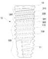
도 3 내지 도 6을 참조하여 본 발명의 상단 몸통부의 함몰부 직경이 확장된 인공치아(10)를 설명하면, 본 발명의 인공치아(10)는 원통형으로 이루어진 티타늄 등의 생체적합성 재질로 이루어져 있으며, 외주면에 굴곡한 단면을 가지는 하단 몸통부(100) 및 상단 몸통부(300)를 포함하고, 상기 하단 몸통부(100) 하부에는 식립시 나사를 스스로 만들 수 있는 셀프태핑(Self Tapping)이 가능한 커팅에지(11)를 포함하며, 상기 상단 몸통부(300)의 상단에는 치아를 지지할 수 있도록 하는 지지대가 결합되는 최상단부(13)을 포함한다.Referring to FIGS. 3 to 6, the
상기 커팅에지(11)는 통상적인 인공치아에 존재하는 구성으로 치조골에 드릴링 한 후 그 드릴링된 내입공으로 본 발명의 인공치아(10)가 식립되는 경우 스스로 나사산을 만들기 용이하도록 하는 기능을 하는데, 이를 셀프태핑(Self Tapping)이라 한다. 이러한 상기 커팅에지(11)의 구성은 종래 인공치아에서 존재하는 구성인 바, 이하에서는 별도의 설명을 하지 아니기로 한다.The
상기 최상단부(13) 또한, 종래 인공치아에 포함된 구성으로 통상적으로 상기 최상단부(13)의 상부에 어버트먼트(치아를 지지하기 위한 지지대)가 설치된다. 이 러한 상기 최상단부(13)는 치아를 지지하는 지대주와의 결합관계에 따라 연결부가 크게 인터널 타입(Internal Type), 익스터널 타입(External Type)으로 구분되며, 이러한 연결에 따른 구성 또한 종래의 인공치아에서 개시된 내용이므로 이하에서는 자세한 설명은 생각하기로 한다.The
상기 하단 몸통부(100)는 본 발명의 인공치아(10)의 하부 원통부를 이루는 부위로써 굴곡된 단면을 가지고 치조골에 접착되어 고정력을 충분히 확보될 수 있도록 형성됨이 바람직하다. 이에 상기 하단 몸통부(100)는 특히 치조골 중 주로 해면골에 위치하는 부위로써 해면골의 강도가 약간 낮은 부위에서 정착되도록 한다. 이에 인체의 치조골을 살펴보면, 먼저 치조골은 피질골과 해면골로 이루어지는데, 피질골이 상부를 덮고 있고, 그 아래에 해면골이 위치한다. 이에 상기 피질골은 비교적 강도가 높은 골조직으로 이루어져 있어 인공치아가 식립된 경우 대부분의 응력을 받는 부위이다. 그러나, 이에 반해 상기 해면골은 비교적 연한 골조직으로 인공치아가 식립되는 경우 응력이 이러한 해면골에까지 미치지 않게 된다. 따라서, 인공치아를 식립하는 경우 상기 피질골에 집중된 응력을 상기 해면골까지 분산시킬 필요가 있게 된다. 이에 상기 하단 몸통부(100)는 돌출부(110)와 함몰부(130)를 포함하는데, 이러한 응력분산의 역할을 하게 된다.The
상기 돌출부(110)는 상기 하단몸통부(100)의 외주면에 형성된 부위로 바람직하게는 도 3에 도시된 바와 같이 나사산의 프로파일을 갖도록 하는 것이 바람직하다. 이러한 상기 돌출부(110)는 해면골에 접하여 상기 해면골과 단단하게 고정될 수 있도록 하는데, 상기에서 살펴본 바와 같이 해면골과의 접촉력 향상을 위해 비 교적 높게 형성되는 것이 바람직하다.The
상기 함몰부(130)는 상기 하단몸통부(100)의 외주면에 형성된 함몰된 부위로써 바람직하게는 도 3에 도시된 것처럼 나사골의 프로파일을 갖도록 하는 것이 바람직하다. 이러한 상기 함몰부(130) 역시 해면골에 접하게 되는데, 상기 해면골의 골조직이 침투하여 표면에 달라붙어 일체화될 수 있도록 하여야 한다.The
상기 상단 몸통부(300)는 본 발명의 인공치아(10)의 상부 원통부에 형성된 부위로써 인공치아가 치조골에 식립시 주로 피질골에 위치하는 부위로 비교적 단단한 상기 피질골에 단단하게 접촉하여 견고히 고정될 수 있도록 한다. 이에 상기 상단 몸통부(300)는 상기 비교적 단단한 피질골에 정착되므로 큰 응력을 지탱하게 되는데, 이러한 상기 피질골의 응력집중을 상기 해면골에 분산시킬 필요가 있게 된다. 특히 전단응력의 경우를 살펴보면, 나사골의 깊이가 깊어질수록 전단응력이 커지게 되는데, 이렇게 커진 전단응력으로 인하여 상기 피질골의 손상이 극심해지고, 심지어는 시술된 인공치아가 이탈되어 재시술을 요하는 경우까지 발생하게 된다. 이에 도 2에 도시된 종래의 발명은 단순히 접촉면적을 넓힘으로써 상기 피질골에 접촉된 상단 몸통부에 집중된 응력을 분산시키는 기능을 하였으나 전단응력을 분산시킬 수 있는 기능은 전혀 없고 상기 피질골에서 발생되는 전단응력을 분산할 수 없는 한계에 이르게 되었다. 이에 본 발명의 인공치아(10)는 도 3에 도시된 것처럼, 단지 상단 몸통부에 집중된 응력을 분산시킬 수 있도록 할 뿐만 아니라, 함몰부의 직경을 넓혀 평탄한 원통부가 일정부분 이루어지도록 함으로써 종래의 피질골에서 높이가 높은 돌출부로 인한 전단응력의 집중을 함몰부 직경을 크게 함으로써 형성되는 돌출부의 낮은 높이로 인해 해면골에 접하는 하단 몸통부로 분산시킬 수 있게 되었다. 이에 상기 상단 몸통부(300)는 돌출부(310), 함몰부(330) 및 홈(350)을 포함한다.The
상기 돌출부(310)는 상기에서 상세히 살펴본 바와 같이 상기 상단 몸통부(300)의 원통형 외주면에 형성된 부위로써 바람직하게는 도 3에 도시된 것처럼 나사산의 프로파일을 갖도록 하여야 할 것이다. 그러나, 이는 바람직한 하나의 실시예일 뿐 반드시 이에 한정된다고 할 것은 아니다. 이에 상기 돌출부(310)는 도 4에 도시된 바와 같이 그 높이(h2)가 상기 하단 몸통부(100)의 돌출부(110)의 높이(h1)에 비해 더 낮도록 형성되는데, 이는 상기에서 언급한 것처럼 피질골에서의 전단응력을 해면골로 분산시킬 수 있도록 하기 위해서이다. 이에 전단응력은 인공치아가 식립된 경우 상하로 작용되는 하중에 의해 세로방향으로 주어지는데, 이에 따라 나사산의 높이가 높을수록 당연히 전단응력의 크기가 커지게 된다. 이에 도 4에 도시된 바와 같이 상단 몸통부(300)의 돌출부(310)의 높이를 조절하여 전단응력을 조금 받도록 할 수 있게 되는 것이다. 더 나아가 하기에서 설명할 함몰부(330)의 직경을 작게 함으로써도 상기 전단응력을 더욱더 효과적으로 분산시킬 수 있게 된다.The
상기 함몰부(330)는 상기에서 상세히 살펴본 바와 같이 상기 상단 몸통부(300)의 원통형 외주면에 형성된 부위로써 바람직하게는 도 3에 도시된 바와 같이 나사골의 프로파일을 갖도록 하여야 할 것이다. 그러나, 상기 돌출부의 경우와 마찬가지로 이는 바람직한 하나의 실시예일 뿐 이에 한정되지는 않는다. 상기 함몰 부(330)는 도 3에 도시된 바와 같이 하단 몸통부(100)의 함몰부(130) 직경(D1)에 비해 더 큰 직경을 갖도록 한다. 상기 상단 몸통부의 함몰부 직경(D2)이 상기 하단 몸통부의 함몰부 직경(D1)에 비해 더 크게 형성됨으로써 골압축량이 상기 상단 몸통부(300)에서 더 늘어나게 되고 이로써 저작력에 의한 피질골의 고정력을 향상시킬 수 있는 효과를 도모할 수 있게 된다. 또한, 상기 상단 몸통부(300)의 함몰부(330)는 도 3에서 보는 바와 같이 일정부분 원통형의 직선구간을 갖게 되므로 전단응력이 상기 직선구간에서 작용되지 아니하는바 더욱더 전단응력을 하부의 하단 몸통부(100)에 분산시킬 수 있는 효과를 도모하게 된다.The
상기 홈(350)은 도 4에 도시된 바와 같이, 상기 상단 몸통부(300)와 하단 몸통부(100)의 경계 부위에 포함되는데, 이렇게 상기 홈(350)을 포함함으로써 스크류 타입의 경우 본 발명의 인공치아(10)를 치조골에 식립시 먼저 하단 몸통부(100)가 피질골에 나사부를 형성하며 식립되고 다음 상기 상단 몸통부(300)가 식립되는데, 이에 상기 홈(350)을 통해 자연스럽게 스스로 나사를 형성할 수 있는 기능을 수행하도록 한다. 이는 상기 커팅에지(11)에서 설명한 바와 같이 셀프태핑(Self Tapping) 기능이라고 하여 상기 홈(350) 역시 상기 커팅에지(11)와 마찬가지로 이러한 기능을 수행할 수 있도록 하는 것이다.As shown in Figure 4, the
본 발명의 또 다른 실시예에 따르면, 도 5에 도시된 바와 같이 상기 상단 몸통부(300)의 함몰부(330)에 오목부(331)을 추가로 포함할 수 있다. 상기 오목부(331)는 상기 원통형의 직선구간을 이루는 상단 몸통부의 함몰부(330)에 더 깊이 작은 골짜기의 형상으로 패인 부분으로써, 바람직하게는 상기 함몰부(330)가 나사 골의 프로파일을 따르는 경우 상기 오목부(331) 또한 나사골의 형상을 따르도록 한다. 이로써 결국 이중 나사골의 형상을 따르게 됨으로써 접촉면적을 추가적으로 넓히게 되고 응력을 분산시키게 된다. 이에 종래에는 이중 나사산을 이용하여 접촉면적을 넓혀 응력을 분산시키는 구조의 픽스츄어(인공치아)의 개시가 있으나, 본 발명에서는 이중 나사골을 이용하여 접촉면적을 넓혀 응력을 분산시키는 인공치아를 제공할 수 있도록 한다. 이렇게 이중 나사골을 이용하여 응력을 분산시키는 경우, 종래 발명에서 이중 나사산을 통해 응력을 분산시키는 것보다 더 좋은 효과를 달성할 수 있는데, 이를 상세히 살펴보면, 먼저 치조골을 이루는 골조직은 골수로 이루어진 피이기 때문에 상기 오목부(331)인 나사골에 침투할 수 있게 된다. 이렇게 침투된 골수는 응고되면서 밀집되어 뼈로 성장해서 결국에는 견고히 상기 오목부(331)인 나사골에 접착되게 된다. 이는 결국 나사골에 뼈자체가 삽입되는 형태이므로 단단한 고정력을 확보할 수 있고, 치조골과의 식립력을 향상시킬 수 있는데, 크게 기여하게 된다. 이는 종래의 이중 나사산의 구조에서는 결코 달성할 수 없는 효과라고 할 것이다.According to another embodiment of the present invention, as shown in FIG. 5, the recessed
이하에서는 본 발명에 따른 상단 몸통부 골지름 확장을 통한 전단응력 분산을 도모하는 인공치아(10)의 사용에 대한 바람직한 실시예 및 작동관계를 첨부된 도면을 참고하여 상세히 설명한다.Hereinafter will be described in detail with reference to the accompanying drawings a preferred embodiment and operation of the use of the artificial tooth (10) to facilitate shear stress distribution through the upper body bone diameter expansion according to the present invention.
도 3은 본 발명의 일 실시예에 따른 상단 몸통부의 골지름이 확장된 인공치아의 입면도이고, 도 4는 본 발명의 다른 실시예에 따른 상단 몸통부의 골지름이 확장된 인공치아의 입면도이며, 도 5는 본 발명의 또 다른 실시예에 따른 상단 몸통부의 골지름이 확장된 인공치아의 입면도이고, 도 6은 본 발명의 또 다른 실시예에 따른 상단 몸통부의 골지름이 확장된 인공치아의 입면도이다.3 is an elevational view of an artificial tooth with an extended valley diameter of the upper body portion according to an embodiment of the present invention, Figure 4 is an elevation view of an artificial tooth with an extended valley diameter of the upper body portion according to another embodiment of the present invention, 5 is an elevational view of an artificial tooth with an extended valley diameter of the upper body according to another embodiment of the present invention, and FIG. 6 is an elevation view of an artificial tooth with an extended valley diameter of an upper body portion according to another embodiment of the present invention. to be.
먼저 도 3 및 도 4를 살펴보면, 본 발명의 인공치아(10)의 함몰부의 직경은 상단 몸통부에서는 D2를 갖고 하단 몸통부에는 D1을 갖는다. 이에 따라 상기 D2는 D1보다 더 크도록 형성되는데, 도 4에서 볼 수 있듯이 상단 몸통부와 하단 몸통부의 돌출부인 나사산은 동일한 나사곡선으로 갖은 피크간 거리를 가지게 되므로 D2가 자연스럽게 더 넓은 직선구간을 가지게 된다. 이에 따라, 본 발명의 인공치아(10)가 식립되어 있는 경우, 전단응력은 동일한 나사골(=함몰부)에서 전단응력을 받는 경우보다 상기 상단 몸통부의 나사골에서 더 작게 받게 되므로 전단응력을 하단 몸통부의 나사골로 분산시킬 수 있는 효과를 도모할 수 있게 된다. 또한, 도 4에 도시된 것처럼 나사산(=돌출부)의 높이도 상단 몸통부의 나사산의 높이가 h2인 반면, 하단 몸통부의 나사산의 높이가 h1으로 형성되어 h1<h2인 관계를 이룸으로써 결국 전단응력이 더 작은 높이의 상단 몸통부의 나사산에서 적게 작용되므로 하단 몸통부의 나사산에 전단응력을 분산시키는 효과를 달성하게 된다. 이와는 별도로 피크간의 길이를 살펴보면, 상기 상단 몸통부(300)의 돌출부(310, 나사산)에서의 피크간 길이(p2)와 상기 하단 몸통부(100)의 돌출부(110, 나사산)에서의 피크간 길이(p1)가 동일하게 유지될 수 있도록 하여 나사의 연속성이 유지되고 리드도 동일하게 되며 이에 따라 본 발명의 인공치아를 식립시 편의성을 도모할 수 있고, 치조골의 손상을 최소화할 수 있게 된다.First, referring to Figures 3 and 4, the diameter of the recessed portion of the
도 5 및 도 6을 참조하여 본 발명의 인공치아(10)에서의 이중 나사골 구조를 설명하면, 본 발명의 인공치아에서 상단 몸통부의 함몰부(330)에 추가로 오목부(331)를 포함할 수 있는데, 이러한 오목부는 상기 함몰부(330)가 나사골의 프로파일을 따를 경우 자연스럽게 역시 작은 나사골의 프로파일을 따르게 되며, 이로써 이중 나사골의 구조를 이루게 된다. 이러한 이중 나사골의 구조는 종래의 이중 나사산의 구조와는 전혀 다른 효과를 달성할 수 있게 되는데, 이러한 이중 나사골에서 작은 나사골에 해당되는 상기 오목부(331)에 치조골의 골수인 피가 침투하게 되어 정착된 후 견고히 고정되면 접촉력을 향상시킬 수 있게 된다. 즉, 이중 나사산의 구조로 형성된 경우라면, 접촉면적은 더 넓어져 응력분산의 효과는 이룰 수 있으나, 치조골이 손상되거나 파괴되는 현상으로 접촉력이 떨어짐에 따라 견고한 고정력을 확보하기 어렵게 된다. 결국, 본 발명의 이중 나사산 구조를 이루는 상기 오목부(331)를 통해 보다 견고한 접촉력 및 고정력을 확보하여 안정된 식립을 이룰 수 있는 인공치아를 도모할 수 있게 된다.Referring to FIGS. 5 and 6, the double screw bone structure of the
또한, 도 4 및 도 6을 참조하여 살펴보면, 본 발명의 인공치아(10)는 식립의 편의성을 위한 샐프태핑(Self Tapping)이 가능한 홈(350)을 추가로 포함할 수 있다. 이러한 홈(350)은 인공치아가 식립되는데, 스스로 나사산을 형성할 수 있도록 하는 것으로 상기 커팅에지(11)와 동일한 기능을 한다. 상기 커팅에지(11)는 전혀 나사산이 형성되지 아니한 드릴링된 식립홈에 나사가 식립될 때, 나사산이 스스로 형성될 수 있는데, 상기 홈(350)은 상기 하단 몸통부(100)가 지나간 피질골에 상기 상단 몸통부(300)의 돌출부(310)가 지나갈 때, 다른 유형의 나사산이 쉽게 형성될 수 있도록 하기 위함이다. 이에 따라, 본 발명의 인공치아(10)를 식립하는 경우 처음에 하단 몸통부(100)가 식립될 때, 상기 커팅에지(11)로 부터 스스로 나사산을 형성될 수 있도록 하고, 다음 상기 하단 몸통부(100)를 지나 상단 몸통부(200)가 식립될 때도 식립이 편의성을 갖도록 할 수 있게 된다.Also, referring to FIGS. 4 and 6, the
앞서 살펴본 실시예는 본 발명이 속하는 기술분야에서 통상의 지식을 가진자(이하 '당업자'라 한다)가 본 발명에 따른 상단 몸통부에서 골지름이 확장된 인공치아를 용이하게 실시할 수 있도록 하는 바람직한 실시예일 뿐, 전술한 실시예 및 첨부된 도면에 한정되는 것은 아니므로 이로 인해 본 발명의 권리범위가 한정되는 것은 아니다. 따라서, 본 발명의 기술적 사상을 벗어나지 않는 범위 내에서 여러가지 치환, 변형 및 변경이 가능하다는 것이 당업자에게 있어 명백할 것이며, 당업자에 의해 용이하게 변경가능한 부분도 본 발명의 권리범위에 포함됨은 자명하다.The above-described embodiment allows a person having ordinary knowledge in the art to which the present invention pertains (hereinafter referred to as a person skilled in the art) to easily implement an artificial tooth having an extended bone diameter in the upper body part according to the present invention. It is only a preferred embodiment, but is not limited to the above-described embodiment and the accompanying drawings, which does not limit the scope of the present invention. Therefore, it will be apparent to those skilled in the art that various substitutions, modifications, and changes can be made without departing from the technical spirit of the present invention, and it is obvious that parts easily changed by those skilled in the art are included in the scope of the present invention.
도 1은 몸통부 전체에 동일한 나사산을 가지는 종래의 인공치아를 나타낸 입면도1 is an elevation view showing a conventional artificial tooth having the same thread throughout the body portion
도 2는 상단부 및 하단부에 상이한 나사산을 가지는 종래의 인공치아를 나타낸 입면도2 is an elevational view of a conventional artificial tooth having different threads at the top and bottom;
도 3은 본 발명의 일 실시예에 따른 상단 몸통부의 골지름이 확장된 인공치아의 입면도3 is an elevational view of an artificial tooth with an extended valley diameter of the upper body portion according to an embodiment of the present invention;
도 4는 본 발명의 다른 실시예에 따른 상단 몸통부의 골지름이 확장된 인공치아의 입면도4 is an elevational view of an artificial tooth with an extended valley diameter of the upper body portion according to another embodiment of the present invention;
도 5는 본 발명의 또 다른 실시예에 따른 상단 몸통부의 골지름이 확장된 인공치아의 입면도5 is an elevational view of an artificial tooth with a bone diameter extended to the upper body portion according to another embodiment of the present invention;
도 6은 본 발명의 또 다른 실시예에 따른 상단 몸통부의 골지름이 확장된 인공치아의 입면도Figure 6 is an elevational view of an artificial tooth with an extended bone diameter of the upper torso according to another embodiment of the present invention
* 도면의 주요부분에 대한 주요 설명 *Major description of the main parts of the drawing
1 : 종래 인공치아1a : 돌출부1: conventional
2 : 종래 인공치아2a : 하단 굴곡부2: conventional
2b : 상단 굴곡부10 : 본 발명의 인공치아2b: upper bend 10: artificial tooth of the present invention
11 : 커팅에지13 : 최상단부11: cutting edge 13: top end
100 : 하단 몸통부110 : 돌출부100: lower body 110: protrusion
130 : 함몰부300 : 상단 몸통부130: depression 300: upper body
310 : 돌출부330 : 함몰부310: protrusion 330: depression
331 : 오목부350 : 홈331: recess 350: groove
D1 : 하단몸통부 함몰부 직경D2 : 상단몸통부 함몰부 직경D1: Lower body depression diameter D2: Upper body depression diameter
h1 : 하단몸통부 돌출부 높이h2 : 상단몸통부 돌출부 높이h1: Lower body protrusion height h2: Upper body protrusion height
p1 : 하단몸통부 돌출부 피크간 거리p2 : 상단몸통부 돌출부 피크간 거리p1: Distance between peaks of lower body protrusions p2: Distance between peaks of lower body protrusions
Claims (10)
Translated fromKoreanPriority Applications (1)
| Application Number | Priority Date | Filing Date | Title |
|---|---|---|---|
| KR1020070132514AKR100950278B1 (en) | 2007-12-17 | 2007-12-17 | Artificial teeth |
Applications Claiming Priority (1)
| Application Number | Priority Date | Filing Date | Title |
|---|---|---|---|
| KR1020070132514AKR100950278B1 (en) | 2007-12-17 | 2007-12-17 | Artificial teeth |
Publications (2)
| Publication Number | Publication Date |
|---|---|
| KR20090065077Atrue KR20090065077A (en) | 2009-06-22 |
| KR100950278B1 KR100950278B1 (en) | 2010-03-31 |
Family
ID=40993531
Family Applications (1)
| Application Number | Title | Priority Date | Filing Date |
|---|---|---|---|
| KR1020070132514AActiveKR100950278B1 (en) | 2007-12-17 | 2007-12-17 | Artificial teeth |
Country Status (1)
| Country | Link |
|---|---|
| KR (1) | KR100950278B1 (en) |
Cited By (1)
| Publication number | Priority date | Publication date | Assignee | Title |
|---|---|---|---|---|
| WO2011013973A3 (en)* | 2009-07-27 | 2011-06-16 | Osstemimplant Co., Ltd. | Dental implant fixture |
Family Cites Families (3)
| Publication number | Priority date | Publication date | Assignee | Title |
|---|---|---|---|---|
| SE514142C2 (en) | 1999-03-09 | 2001-01-08 | Nobel Biocare Ab | Self-tapping implants |
| WO2002062255A1 (en)* | 2001-02-02 | 2002-08-15 | Friadent Gmbh | Implant system |
| US7396231B2 (en) | 2005-03-07 | 2008-07-08 | Niznick Gerald A | Flared implant extender for endosseous dental implants |
- 2007
- 2007-12-17KRKR1020070132514Apatent/KR100950278B1/enactiveActive
Cited By (3)
| Publication number | Priority date | Publication date | Assignee | Title |
|---|---|---|---|---|
| WO2011013973A3 (en)* | 2009-07-27 | 2011-06-16 | Osstemimplant Co., Ltd. | Dental implant fixture |
| CN102470023A (en)* | 2009-07-27 | 2012-05-23 | 奥齿泰有限责任公司 | Dental implant fixture |
| US9855119B2 (en) | 2009-07-27 | 2018-01-02 | Osstemimplant Co., Ltd. | Dental implant fixture |
Also Published As
| Publication number | Publication date |
|---|---|
| KR100950278B1 (en) | 2010-03-31 |
Similar Documents
| Publication | Publication Date | Title |
|---|---|---|
| US6981873B2 (en) | Dental implant and head for a compaction drill | |
| US5816812A (en) | Dental implant fixture | |
| US8029285B2 (en) | Implant, arrangement comprising an implant, and method for inserting said implant in bone tissue | |
| US4624673A (en) | Device system for dental prosthesis fixation to bone | |
| CA2109850C (en) | Anchoring element for anchorage in bone tissue | |
| RU2459594C2 (en) | Post-extraction dental implant | |
| US20050019730A1 (en) | Dental minipin with interchangeable abutments | |
| US20090220914A1 (en) | Dental implant and a method of implantation thereof | |
| US20080064010A1 (en) | Intra-Osseous Implant | |
| WO2007086622A1 (en) | Fixture | |
| KR101092312B1 (en) | Fixture of Dental Implant | |
| ES2363527T3 (en) | IMPLANT. | |
| KR20160130838A (en) | Dental implant | |
| KR100860356B1 (en) | A dendtal implant | |
| KR102500190B1 (en) | Advanced self-tapping dental implant system with prosthesis abutment, hybrid connection between implant and internal screw and parallel double conical locking | |
| KR101025225B1 (en) | Dental Implant Fixtures | |
| KR100950278B1 (en) | Artificial teeth | |
| KR100894986B1 (en) | Screw Type Dental Implant Fixtures | |
| KR101452477B1 (en) | Press fit dental implant with multiple longituinal teeth | |
| KR100594752B1 (en) | Dental Implant Fixtures | |
| KR100598937B1 (en) | Picture for root tooth artificial tooth procedure with cutting edge | |
| KR20190122285A (en) | Dental Implant | |
| KR20140077128A (en) | Anchoring element and method | |
| KR101059741B1 (en) | Mini implant | |
| KR200377963Y1 (en) | Dental Implant Fixture |
Legal Events
| Date | Code | Title | Description |
|---|---|---|---|
| A201 | Request for examination | ||
| PA0109 | Patent application | Patent event code:PA01091R01D Comment text:Patent Application Patent event date:20071217 | |
| PA0201 | Request for examination | ||
| PG1501 | Laying open of application | ||
| E902 | Notification of reason for refusal | ||
| PE0902 | Notice of grounds for rejection | Comment text:Notification of reason for refusal Patent event date:20100121 Patent event code:PE09021S01D | |
| E701 | Decision to grant or registration of patent right | ||
| PE0701 | Decision of registration | Patent event code:PE07011S01D Comment text:Decision to Grant Registration Patent event date:20100322 | |
| GRNT | Written decision to grant | ||
| PR0701 | Registration of establishment | Comment text:Registration of Establishment Patent event date:20100323 Patent event code:PR07011E01D | |
| PR1002 | Payment of registration fee | Payment date:20100324 End annual number:3 Start annual number:1 | |
| PG1601 | Publication of registration | ||
| FPAY | Annual fee payment | Payment date:20130306 Year of fee payment:4 | |
| PR1001 | Payment of annual fee | Payment date:20130306 Start annual number:4 End annual number:4 | |
| FPAY | Annual fee payment | Payment date:20140221 Year of fee payment:5 | |
| PR1001 | Payment of annual fee | Payment date:20140221 Start annual number:5 End annual number:5 | |
| FPAY | Annual fee payment | Payment date:20150302 Year of fee payment:6 | |
| PR1001 | Payment of annual fee | Payment date:20150302 Start annual number:6 End annual number:6 | |
| FPAY | Annual fee payment | Payment date:20160222 Year of fee payment:7 | |
| PR1001 | Payment of annual fee | Payment date:20160222 Start annual number:7 End annual number:7 | |
| FPAY | Annual fee payment | Payment date:20170125 Year of fee payment:8 | |
| PR1001 | Payment of annual fee | Payment date:20170125 Start annual number:8 End annual number:8 | |
| FPAY | Annual fee payment | Payment date:20171222 Year of fee payment:9 | |
| PR1001 | Payment of annual fee | Payment date:20171222 Start annual number:9 End annual number:9 | |
| FPAY | Annual fee payment | Payment date:20190328 Year of fee payment:10 | |
| PR1001 | Payment of annual fee | Payment date:20190328 Start annual number:10 End annual number:10 | |
| FPAY | Annual fee payment | Payment date:20200226 Year of fee payment:11 | |
| PR1001 | Payment of annual fee | Payment date:20200226 Start annual number:11 End annual number:11 | |
| PR1001 | Payment of annual fee | Payment date:20210223 Start annual number:12 End annual number:12 | |
| PR1001 | Payment of annual fee | Payment date:20220302 Start annual number:13 End annual number:13 |