KR20090063702A - Signal processor and control method - Google Patents
Signal processor and control methodDownload PDFInfo
- Publication number
- KR20090063702A KR20090063702AKR1020070131160AKR20070131160AKR20090063702AKR 20090063702 AKR20090063702 AKR 20090063702AKR 1020070131160 AKR1020070131160 AKR 1020070131160AKR 20070131160 AKR20070131160 AKR 20070131160AKR 20090063702 AKR20090063702 AKR 20090063702A
- Authority
- KR
- South Korea
- Prior art keywords
- input
- signal
- units
- unit
- signal processing
- Prior art date
- Legal status (The legal status is an assumption and is not a legal conclusion. Google has not performed a legal analysis and makes no representation as to the accuracy of the status listed.)
- Withdrawn
Links
Images


Classifications
- H—ELECTRICITY
- H04—ELECTRIC COMMUNICATION TECHNIQUE
- H04N—PICTORIAL COMMUNICATION, e.g. TELEVISION
- H04N5/00—Details of television systems
- H04N5/222—Studio circuitry; Studio devices; Studio equipment
- H04N5/262—Studio circuits, e.g. for mixing, switching-over, change of character of image, other special effects ; Cameras specially adapted for the electronic generation of special effects
- H04N5/268—Signal distribution or switching
- H—ELECTRICITY
- H04—ELECTRIC COMMUNICATION TECHNIQUE
- H04N—PICTORIAL COMMUNICATION, e.g. TELEVISION
- H04N5/00—Details of television systems
- H04N5/44—Receiver circuitry for the reception of television signals according to analogue transmission standards
- H—ELECTRICITY
- H04—ELECTRIC COMMUNICATION TECHNIQUE
- H04N—PICTORIAL COMMUNICATION, e.g. TELEVISION
- H04N21/00—Selective content distribution, e.g. interactive television or video on demand [VOD]
- H04N21/40—Client devices specifically adapted for the reception of or interaction with content, e.g. set-top-box [STB]; Operations thereof
- H04N21/41—Structure of client; Structure of client peripherals
- H04N21/422—Input-only peripherals, i.e. input devices connected to specially adapted client devices, e.g. global positioning system [GPS]
- H04N21/42204—User interfaces specially adapted for controlling a client device through a remote control device; Remote control devices therefor
- H—ELECTRICITY
- H04—ELECTRIC COMMUNICATION TECHNIQUE
- H04N—PICTORIAL COMMUNICATION, e.g. TELEVISION
- H04N21/00—Selective content distribution, e.g. interactive television or video on demand [VOD]
- H04N21/40—Client devices specifically adapted for the reception of or interaction with content, e.g. set-top-box [STB]; Operations thereof
- H04N21/43—Processing of content or additional data, e.g. demultiplexing additional data from a digital video stream; Elementary client operations, e.g. monitoring of home network or synchronising decoder's clock; Client middleware
- H04N21/436—Interfacing a local distribution network, e.g. communicating with another STB or one or more peripheral devices inside the home
- H—ELECTRICITY
- H04—ELECTRIC COMMUNICATION TECHNIQUE
- H04N—PICTORIAL COMMUNICATION, e.g. TELEVISION
- H04N21/00—Selective content distribution, e.g. interactive television or video on demand [VOD]
- H04N21/40—Client devices specifically adapted for the reception of or interaction with content, e.g. set-top-box [STB]; Operations thereof
- H04N21/43—Processing of content or additional data, e.g. demultiplexing additional data from a digital video stream; Elementary client operations, e.g. monitoring of home network or synchronising decoder's clock; Client middleware
- H04N21/442—Monitoring of processes or resources, e.g. detecting the failure of a recording device, monitoring the downstream bandwidth, the number of times a movie has been viewed, the storage space available from the internal hard disk
- H04N21/44231—Monitoring of peripheral device or external card, e.g. to detect processing problems in a handheld device or the failure of an external recording device
- H—ELECTRICITY
- H04—ELECTRIC COMMUNICATION TECHNIQUE
- H04N—PICTORIAL COMMUNICATION, e.g. TELEVISION
- H04N21/00—Selective content distribution, e.g. interactive television or video on demand [VOD]
- H04N21/40—Client devices specifically adapted for the reception of or interaction with content, e.g. set-top-box [STB]; Operations thereof
- H04N21/47—End-user applications
- H04N21/485—End-user interface for client configuration
Landscapes
- Engineering & Computer Science (AREA)
- Multimedia (AREA)
- Signal Processing (AREA)
- Human Computer Interaction (AREA)
- Automation & Control Theory (AREA)
- Computer Networks & Wireless Communication (AREA)
- Databases & Information Systems (AREA)
- Two-Way Televisions, Distribution Of Moving Picture Or The Like (AREA)
Abstract
Description
Translated fromKorean본 발명은 신호처리장치 및 그 제어방법에 관한 것이다. 더욱 상세하게는, 본 발명은 복수의 입력잭을 통해 복수의 입력신호를 입력받는 신호처리장치 및 그 제어방법에 관한 것이다.The present invention relates to a signal processing apparatus and a control method thereof. More specifically, the present invention relates to a signal processing apparatus for receiving a plurality of input signals through a plurality of input jacks and a control method thereof.
TV, 셋톱박스 등의 신호처리장치는 외부의 신호공급원으로부터 복수의 신호를 입력받을 수 있다. 예컨대, TV는 비디오 및 DVD플레이어 등의 외부장치와 연결되어 다양한 형식의 영상신호를 입력받을 수 있다.Signal processing apparatuses such as a TV and a set top box may receive a plurality of signals from an external signal source. For example, the TV may be connected to an external device such as a video and a DVD player to receive various types of video signals.
신호처리장치는 입력단자부를 통해 신호를 입력받는다. 입력단자의 종류로는 HDMI(High-Definition Multimedia Interface)단자, 컴포지트(Composite)단자, S-비디오단자, 컴포넌트(Component)단자 등이 있다. 컴포지트단자는 일상적인 아날로그 연결에 가장 자주 쓰이는 연결 단자이다. RCA케이블이 이러한 컴포지트 연결에 주로 쓰인다. 컴포지트단자는 영상의 Y(휘도신호), C(색상신호)신호가 합쳐져서 전송되는 것을 의미한다. S-비디오단자 혹은 Y/C단자는 Y, C신호가 분리되어서 전송되는 것을 의미한다.The signal processing apparatus receives a signal through an input terminal unit. Types of input terminals include a high-definition multimedia interface (HDMI) terminal, a composite terminal, an S-video terminal, and a component terminal. Composite terminals are the connections most often used for everyday analog connections. RCA cables are often used for these composite connections. The composite terminal means that the Y (luminance signal) and C (color signal) signals of the image are transmitted together. S-video terminal or Y / C terminal means that Y and C signals are transmitted separately.
컴포넌트 단자는 영상신호가 Y, Pb, Pr신호로 분리되서 입력된다. Y, Pb, Pr의 의미는 Y신호는 휘도신호이고 Pb는 블루색상신호, Pr은 레드색상신호이다. 그린색상신호는 휘도신호에 포함되어 있다. 신호를 나누어 전송하면 신호간섭이 줄어들어 더욱 선명한 화질의 영상을 제공할 수 있다.The component terminal is input by separating the video signal into Y, Pb, and Pr signals. The meaning of Y, Pb, and Pr is that the Y signal is a luminance signal, Pb is a blue color signal, and Pr is a red color signal. The green color signal is included in the luminance signal. By dividing the signal, signal interference is reduced, so that a clearer image can be provided.
컴포지트 단자는 RCA케이블 한 가닥으로 영상 신호를 전송하는데 반해 컴포넌트단자는 Y, Pb, Pr을 각각 한 가닥씩 나누어 영상 신호를 전송한다. 또한 영상신호 외에 스테레오 방식의 음성신호는 오른쪽(R) 및 왼쪽(L)음성신호로 분리 되서 입력될 수 있다. 즉, 신호처리장치가 컴포넌트 방식의 영상신호나 스테레오 방식의 음성신호를 입력받기 위해서는 복수의 입력단자가 필요하다.The composite terminal transmits the video signal through one strand of the RCA cable, while the component terminal transmits the video signal by dividing Y, Pb and Pr into one strand. In addition to the video signal, the stereo audio signal may be input into a right (R) and a left (L) audio signal. That is, a plurality of input terminals are required for the signal processing apparatus to receive a component video signal or a stereo audio signal.
그런데 종래의 신호처리장치는 사용자가 입력잭을 입력단자에 잘못 연결했을 경우, 사용자가 잘못 연결된 입력단자를 찾아 일일이 재연결해야 하는 불편함이 있다. 예컨대, 컴포넌트 단자의 경우 Y, Pb, Pr 세 개의 단자로 구성되는데, 그 입력잭의 형태가 동일하기 때문에 잘못 연결할 가능성이 크다.However, in the conventional signal processing apparatus, when a user incorrectly connects an input jack to an input terminal, the user needs to find an incorrectly connected input terminal and reconnect one by one. For example, a component terminal is composed of three terminals of Y, Pb, and Pr. Since the input jacks are the same type, there is a high possibility of wrong connection.
또한 입력단자의 종류 및 개수가 증가함에 따라 주변기기들을 입력단자에 정확히 연결하기 위해서는 사용자에게 상당한 사전지식이 요구되어 진다. 따라서 신호처리장치는 사용자에게 입력단자의 연결 상태에 대한 정보를 정확하고 이해하기 쉬운 형태로 전달할 필요가 있다.In addition, as the type and number of input terminals increase, considerable prior knowledge is required for a user to accurately connect peripheral devices to the input terminals. Therefore, the signal processing apparatus needs to deliver information about the connection state of the input terminal to the user in an accurate and easy form.
본 발명은 상기 문제점을 해결하기 위한 것으로서, 잘못 연결된 입력단자를 보다 쉽게 재연결할 수 있는 신호처리장치 및 그 제어방법을 제공하는 것을 목적으로 한다.An object of the present invention is to provide a signal processing apparatus and a method of controlling the same, which can easily reconnect an incorrectly connected input terminal.
또한, 입력단자의 연결 상태에 대한 정보를 정확하고 이해하기 쉬운 형태로 전달할 수 있는 신호처리장치 및 그 제어방법을 제공하는 것을 목적으로 한다.Another object of the present invention is to provide a signal processing apparatus and a control method thereof capable of transmitting information on a connection state of an input terminal in an accurate and easy form.
상기 목적을 달성하기 위하여, 본 발명은, 신호처리장치에 있어서, 복수의 입력잭이 각각 연결될 수 있는 복수의 입력단자부와; 복수의 입력잭으로부터 입력되는 복수의 입력신호 각각에 대응하는 복수의 접속부를 포함하고, 복수의 입력신호를 복수의 접속부를 통해 입력받아 처리하는 신호처리부와; 복수의 입력단자부와, 복수의 접속부 사이에 마련되어, 복수의 입력단자부를 복수의 접속부에 선택적으로 연결하는 스위칭부와; 복수의 입력신호에 대한 정보를 검출하는 정보검출부와; 정보검출부에 의해 검출된 정보에 따라 복수의 입력신호와, 복수의 접속부가 상호 대응하도록 스위칭부를 제어하는 제어부를 포함하는 것을 특징으로 하는 신호처리장치를 제공한다.In order to achieve the above object, the present invention provides a signal processing apparatus comprising: a plurality of input terminal units to which a plurality of input jacks can be connected; A signal processing unit including a plurality of connection units corresponding to each of the plurality of input signals inputted from the plurality of input jacks, and receiving and processing the plurality of input signals through the plurality of connection units; A switching unit provided between the plurality of input terminal units and the plurality of connection units and selectively connecting the plurality of input terminal units to the plurality of connection units; An information detecting unit detecting information on the plurality of input signals; According to the information detected by the information detecting unit provides a signal processing apparatus comprising a control unit for controlling the switching unit so that the plurality of input signals and the plurality of connection portions correspond to each other.
또한 신호처리장치는, 신호처리부에서 처리된 입력신호에 기초하여 표시하는 표시부를 더 포함할 수 있고, 복수의 입력잭과 복수의 입력단자부와의 연결 상태를 표시부에 표시하는 것이 바람직하다.The signal processing apparatus may further include a display unit for displaying based on the input signal processed by the signal processor, and preferably displays the connection state between the plurality of input jacks and the plurality of input terminal units on the display unit.
또한 신호처리장치는, 사용자의 명령을 입력받는 사용자입력부를 더 포함할 수 있고, 제어부는, 사용자의 입력에 따라 복수의 입력신호와, 복수의 접속부가 상호 대응하도록 스위칭부를 제어할 수 있는 것이 바람직하다.The signal processing apparatus may further include a user input unit configured to receive a user's command, and the controller may control the switching unit such that the plurality of input signals and the plurality of connection units correspond to each other according to the user's input. Do.
또한 신호처리장치는, 정보검출부에 의해 검출된 정보에 기초하여 UI를 생성하는 UI생성부를 더 포함할 수 있다.The signal processing apparatus may further include a UI generator that generates a UI based on the information detected by the information detector.
정보검출부는, 복수의 입력신호 중 Y신호는 동기신호의 존재여부로 판별하고, Pb 및 Pr 신호는 위상차로 판별할 수 있다.The information detector may determine whether the Y signal is present among the plurality of input signals by the presence of the synchronization signal, and the Pb and Pr signals by the phase difference.
복수의 입력단자부는, 복수의 입력잭 각각의 연결여부를 감지할 수 있고, 복수의 입력잭 각각에 대응하여 표시가 되어 있을 수 있다.The plurality of input terminal units may detect whether each of the plurality of input jacks is connected, and may be displayed corresponding to each of the plurality of input jacks.
입력신호는 음성신호를 포함할 수 있다.The input signal may include a voice signal.
한편, 본 발명은, 복수의 입력신호 각각에 대응하는 복수의 접속부를 포함하고, 복수의 입력신호를 복수의 접속부를 통해 입력받아 처리하는 신호처리부를 포함하는 신호처리장치의 제어방법에 있어서, 복수의 입력잭으로부터 입력되는 복수의 입력신호에 대한 정보를 검출하는 단계와; 검출된 정보에 따라 복수의 입력신호와, 복수의 접속부를 상호 대응시키는 단계를 포함하는 것을 특징으로 하는 신호처리장치의 제어방법에 의해서도 상기 목적을 달성할 수 있다.On the other hand, the present invention is a control method of a signal processing apparatus comprising a plurality of connection portions corresponding to each of a plurality of input signals, and a signal processing unit for receiving and processing a plurality of input signals through a plurality of connection portions, Detecting information on a plurality of input signals input from an input jack of the apparatus; The above object can also be attained by a control method of a signal processing apparatus comprising the step of correlating a plurality of input signals and a plurality of connection units according to the detected information.
또한 신호처리장치의 제어방법은, 복수의 입력잭과 복수의 입력단자부와의 연결 상태를 표시하는 단계를 더 포함하는 것이 바람직하다.In addition, the control method of the signal processing apparatus, preferably further comprises the step of displaying the connection state of the plurality of input jacks and the plurality of input terminal portion.
대응시키는 단계는, 사용자의 입력에 따라 복수의 입력신호와, 복수의 접속부를 상호 대응시키는 단계를 포함하는 것이 바람직하다.The correspondence step preferably includes the correspondence of the plurality of input signals and the plurality of connection parts according to a user input.
또한 신호처리장치의 제어방법은, 검출된 정보에 기초하여 UI를 생성하는 단계를 더 포함할 수 있다.The control method of the signal processing apparatus may further include generating a UI based on the detected information.
검출하는 단계는, 복수의 입력신호 중 Y신호는 동기신호의 존재여부로 판별 하고, Pb 및 Pr 신호는 위상차로 판별하는 단계와, 복수의 입력잭 각각의 연결여부를 감지하는 단계를 포함할 수 있다.The detecting may include determining whether a Y signal is a presence of a synchronization signal among the plurality of input signals, determining a Pb and Pr signal by a phase difference, and detecting whether each of the plurality of input jacks is connected. have.
입력신호는 음성신호를 포함할 수 있다.The input signal may include a voice signal.
본 발명에 의하면, 신호처리장치 및 그 제어방법은 잘못 연결된 입력단자를 보다 쉽게 재연결할 수 있다.According to the present invention, the signal processing apparatus and its control method can more easily reconnect an incorrectly connected input terminal.
또한, 신호처리장치 및 그 제어방법은 입력단자의 연결 상태에 대한 정보를 정확하고 이해하기 쉬운 형태로 전달할 수 있다.In addition, the signal processing apparatus and its control method can deliver information about the connection state of the input terminal in an accurate and easy to understand form.
이하, 첨부된 도면을 참조하여 본 발명의 일실시예에 관하여 상세히 설명한다.Hereinafter, with reference to the accompanying drawings will be described in detail an embodiment of the present invention.
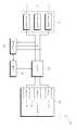
도 1은 본 발명의 일실시예에 따른 신호처리장치(100)의 구성을 도시한 블록도이다. 본 발명의 일실시예에 따른 신호처리장치(100)는 복수의 입력잭을 통해 복수의 입력신호를 입력받을 수 있다. 예컨대, 신호처리장치(100)는 TV, 셋톱박스 등으로 구현되어 복수의 RCA 입력단자를 통해 컴포넌트 방식의 영상신호나 스테레오 방식의 음성신호를 입력받을 수 있다.1 is a block diagram showing the configuration of a
도 1에 도시된 바와 같이, 신호처리장치(100)는 복수의 입력단자부(110), 스위칭부(120), 신호처리부(130), 표시부(140), 정보검출부(150), UI생성부(160), 사용자입력부(170) 및 제어부(180)를 포함할 수 있다.As shown in FIG. 1, the
복수의 입력단자부(110)는 복수의 입력잭(도시 안 됨)이 각각 연결될 수 있 다. 예컨대, 입력잭은 일반적으로 가장 많이 사용되는 RCA잭일 수 있고, 복수의 입력단자부(110)는 Y, Pb, Pr신호를 입력받을 수 있는 3개의 RCA단자로 구현될 수 있다.The plurality of
또한 복수의 입력단자부(110)는 복수의 입력잭 각각의 연결여부를 감지할 수 있다. 예컨대, 각각의 입력잭에는 입력잭의 연결에 따라 기계적으로 스위칭동작이 일어나는 회로가 마련될 수 있다. 입력단자에 입력잭이 연결된 경우, 입력단자는 하이(high) 또는 로우(low)신호를 출력하게 된다. 복수의 입력단자부(110)의 구조 및 출력신호는 다양할 수 있다.In addition, the plurality of
또한 복수의 입력단자부(110)는 복수의 입력잭 각각에 대응하는 표시가 되어 있을 수 있다. 예컨대, 사용자 편의를 위해 영상신호 입력단자에는 Y, Pb, Pr 별로 음성신호 단자는 R, L별로 문자 또는 그림 등으로 표시되어 있는 것이 바람직하다.In addition, the plurality of
스위칭부(120)는 복수의 입력단자부(110)와, 복수의 접속부(131,132,133) 사이에 마련되어, 복수의 입력단자부(110)를 복수의 접속부(131,132,133)에 선택적으로 연결한다. 스위칭부(120)는 제어부(180)의 제어에 따라 입력단자부(111,112,113) 각각을 어느 하나의 접속부(131,132,133)에 선택적으로 연결한다.The
신호처리부(130)는 복수의 입력잭으로부터 입력되는 복수의 입력신호 각각에 대응하는 복수의 접속부(131,132,133)를 포함하고, 복수의 입력신호를 복수의 접속부(131,132,133)를 통해 입력받아 처리한다. 입력신호는 영상신호뿐만 아니라 음성신호를 포함할 수 있다.The
예컨대, 접속부1(131)은 Y신호를 입력받고, 접속부2(132)는 Pb신호를 입력받 고, 접속부3(133)은 Pr신호를 입력받을 수 있다. 또한, 신호처리부(120)는 컴포넌트 신호처리모듈(도시 안 됨) 및 스테레오 음성신호 처리모듈(도시 안 됨)을 포함할 수 있다.For example, the
표시부(140)는 신호처리부(130)에서 처리된 입력신호에 기초하여 표시한다. 표시부(140)는 영상신호 출력을 위해 CRT(cathode ray tube), LCD(liquid crystal display), PDP(plasma display panel)등의 형태로 구현될 수 있으며, 음성신호 출력을 위해 스피커 등으로 구현될 수도 있다.The
정보검출부(150)는 복수의 입력신호에 대한 정보를 검출한다. 구체적으로, 정보검출부(150)는 복수의 입력신호 중 Y신호는 동기신호의 존재여부로 판별하고, Pb 및 Pr 신호는 위상차로 판별할 수 있다.The
예컨대, 정보검출부(150)는 각 입력단자부(111,112,113)를 통해 입력된 입력신호에 동기신호가 있는지 판별하여 동기신호가 존재할 경우, 해당 입력단자로 Y신호가 입력되고 있음을 판단한다. 다음으로 Y신호가 입력되는 입력단자 외의 입력단자에서 색차신호의 위상차를 판별하여 Pb, Pr신호가 입력되는 입력단자를 판단할 수 있다. 입력신호에 대한 정보는 입력신호의 종류에 따라 다양할 수 있으며, 사용자에 의해 설정될 수도 있다.For example, the
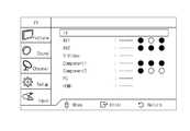
UI생성부(160)는 정보검출부(150)에 의해 검출된 정보에 기초하여 UI를 생성한다. UI생성부(160)는 OSD처리부로 구현될 수 있으며, 신호처리부(130)에 포함될 수도 있다. 도 2a 및 도 2b에 도시된 바와 같이, UI는 문자 또는 기호를 이용하여 AV신호 및 컴포넌트 신호 별로 각 입력단자의 연결 상태를 상세하고 쉽게 파악할 수 있도록 표시될 수 있다.The
사용자입력부(170)는 사용자의 명령을 입력받는다. 예컨대, 사용자입력부(170)는 리모콘 등으로 구현될 수 있고, 사용자의 입력을 받아 제어부(180)에 전달한다.The
제어부(180)는 정보검출부(150)에 의해 검출된 정보에 따라 복수의 입력신호와, 복수의 접속부(131,132,133)가 상호 대응하도록 스위칭부(120)를 제어한다.The
예컨대, 신호처리부(130)의 접속부1(131)은 Y신호 단자이고, 접속부2(132)는 Pb신호 단자이고, 접속부3(133)은 Pr신호 단자라고 가정하자. 정보검출부(150)의 검출 결과 입력단자1(111)을 통해 Y신호가 입력되고, 입력단자2(112)를 통해 Pb신호, 입력단자3(113)을 통해 Pr신호가 입력되는 것으로 판단된 경우, 제어부(180)는 입력단자1(111)은 접속부1(131)에, 입력단자2(112)는 접속부2(132)에, 입력단자3(113)은 접속부3(133)에 연결되도록 스위칭부(120)를 제어한다.For example, suppose that the
제어부(180)는 복수의 입력잭과 복수의 입력단자부(110)와의 연결 상태를 표시부(140)에 표시하도록 할 수 있다. 도 2a 및 도 2b에 도시된 바와 같이, 제어부(180)는 UI생성부(160)를 제어하여 입력신호 별로 각 입력단자의 연결 상태를 상세하고 쉽게 파악할 수 있는 UI를 표시하도록 할 수 있다.The
또한 제어부(180)는 사용자의 입력에 따라 복수의 입력신호와, 복수의 접속부(131,132,133)가 상호 대응하도록 스위칭부(120)를 제어할 수 있는 것이 바람직하다. 구체적으로, 신호처리장치(100)는 먼저 입력신호를 처리하여 표시부(140)에 표시하고, 영상이 정상적으로 표시되는지 여부를 사용자에게 확인한다. 만약 영상 이 제대로 표시되지 않을 경우, 정보검출부(150)에 의해 검출된 정보에 따라 복수의 입력신호와, 복수의 접속부(131,132,133)가 상호 대응하도록 스위칭부(120)를 제어할 수 있다.In addition, the
즉, 신호처리장치(100)는 자동으로 스위칭하여 입력신호를 처리할 수 있고, 먼저 입력신호를 처리하여 표시한 후 이상이 있을 경우 사용자의 입력에 따라 스위칭하여 입력신호를 처리할 수도 있다.That is, the
도 3은 본 발명의 다른 실시예에 따른 신호처리장치(100A)의 구성을 도시한 블록도이다. 도 3에 도시된 바와 같이, 신호처리장치(100A)는 복수의 입력단자부(110), 스위칭부(120), 신호처리부(130), 정보검출부(150) 및 제어부(180)를 포함하여 구성될 수도 있다. 본 실시예의 신호처리장치(100A)에 관하여 상기 도 1과 관련하여 설명된 신호처리장치(100)와 동일 내지는 유사한 구성에 대한 설명은 생략한다.3 is a block diagram showing the configuration of a
이하에서는, 도 4를 참조하여 본 발명의 일실시예에 따른 신호처리장치(100)의 제어방법을 설명한다.Hereinafter, a control method of the
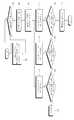
먼저, 신호처리장치(100)는 입력신호 정보를 검출한다(S10). 정보검출부(150)는 복수의 입력신호 중 Y신호는 동기신호의 존재여부로 판별하고, Pb 및 Pr 신호는 위상차로 판별할 수 있다.First, the
입력단자1(111)을 통해 입력되는 입력신호에 동기신호가 존재하는지 여부를 판별한다(S21). 단계 S21에서 동기신호가 존재할 경우, 입력단자2,3은 Pb, Pr신호로 판단한다(S31).It is determined whether a synchronization signal exists in the input signal input through the
단계 S21에서 동기신호가 존재하지 않을 경우, 입력단자2(112)를 통해 입력되는 입력신호에 동기신호가 존재하는지 여부를 판별한다(S22). 단계 S22에서 동기신호가 존재할 경우, 입력단자1,3은 Pb, Pr신호로 판단한다(S32).If there is no synchronization signal in step S21, it is determined whether a synchronization signal exists in the input signal input through the input terminal 2 (112) (S22). If there is a synchronization signal in step S22, the
단계 S22에서 동기신호가 존재하지 않을 경우, 입력단자3(113)을 통해 입력되는 입력신호에 동기신호가 존재하는지 여부를 판별한다(S23). 단계 S23에서 동기신호가 존재할 경우, 입력단자1,2는 Pb, Pr신호로 판단한다(S33).If there is no synchronization signal in step S22, it is determined whether a synchronization signal exists in the input signal input through the input terminal 3 (113) (S23). If there is a synchronization signal in step S23, the
단계 S23에서 동기신호가 존재하지 않을 경우, 에러 메시지를 표시한다(S40). 콤포넌트 입력단자의 모든 입력신호에 Y신호가 존재하지 않는다는 것이므로 에러 메시지 또는 영상 메시지가 아님을 표시한다.If there is no synchronization signal in step S23, an error message is displayed (S40). Since the Y signal does not exist in all the input signals of the component input terminal, it indicates that it is not an error message or a video message.
다음으로, 신호처리장치(100)는 입력신호를 처리하여 영상을 디스플레이한다(S50). 그리고 OSD로 메시지를 표시하여 사용자에게 정상적인 영상이 표시되는지 여부를 확인한다(S60). 신호처리장치(100)는 사용자가 스왑기능을 선택했는지 판단한다(S70).Next, the
단계 S70에서 스왑기능이 선택된 경우, 신호처리장치(100)는 Pb, Pr신호가 입력되는 것으로 판단된 입력단자 2개를 서로 스위칭한다(S80). 즉, 신호처리장치(100)는 먼저 입력신호를 처리하여 표시부(140)에 표시하고, 영상이 정상적으로 표시되는지 여부를 사용자에게 확인한다. 만약 영상이 제대로 표시되지 않을 경우, 정보검출부(150)에 의해 검출된 정보에 따라 복수의 입력신호와, 복수의 접속부(131,132,133)가 상호 대응하도록 스위칭부(120)를 제어할 수 있다.When the swap function is selected in step S70, the
이상, 바람직한 실시예를 통하여 본 발명에 관하여 상세히 설명하였으나, 본 발명은 이에 한정되는 것은 아니며 특허청구범위 내에서 다양하게 실시될 수 있다.As mentioned above, the present invention has been described in detail through preferred embodiments, but the present invention is not limited thereto and may be variously implemented within the scope of the claims.
도 1은 본 발명의 일실시예에 따른 신호처리장치의 구성을 도시한 블록도이며,1 is a block diagram showing the configuration of a signal processing apparatus according to an embodiment of the present invention;
도 2a 및 도 2b는 본 발명의 일실시예에 따른 신호처리장치 UI를 도시한 도면이고,2A and 2B illustrate a signal processing apparatus UI according to an embodiment of the present invention.
도 3은 본 발명의 다른 실시예에 따른 신호처리장치의 구성을 도시한 블록도이다.3 is a block diagram showing the configuration of a signal processing apparatus according to another embodiment of the present invention.
도 4는 본 발명의 일실시예에 따른 신호처리장치의 동작 과정을 도시한 흐름도이다.4 is a flowchart illustrating an operation of a signal processing apparatus according to an embodiment of the present invention.
*도면의 주요 부분에 대한 부호의 설명* Explanation of symbols for the main parts of the drawings
100 : 신호처리장치 110 : 복수의 입력단자부100: signal processing device 110: a plurality of input terminal unit
120 : 스위칭부 130 : 신호처리부120: switching unit 130: signal processing unit
140 : 표시부 150 : 정보검출부140: display unit 150: information detection unit
160 : UI생성부 170 : 사용자입력부160: UI generation unit 170: user input unit
180 : 제어부180: control unit
Claims (16)
Translated fromKoreanPriority Applications (3)
| Application Number | Priority Date | Filing Date | Title |
|---|---|---|---|
| KR1020070131160AKR20090063702A (en) | 2007-12-14 | 2007-12-14 | Signal processor and control method |
| US12/141,148US20090157917A1 (en) | 2007-12-14 | 2008-06-18 | Signal processing apparatus and control method thereof |
| EP08171122AEP2071829A1 (en) | 2007-12-14 | 2008-12-09 | Signal processing apparatus and control method thereof |
Applications Claiming Priority (1)
| Application Number | Priority Date | Filing Date | Title |
|---|---|---|---|
| KR1020070131160AKR20090063702A (en) | 2007-12-14 | 2007-12-14 | Signal processor and control method |
Publications (1)
| Publication Number | Publication Date |
|---|---|
| KR20090063702Atrue KR20090063702A (en) | 2009-06-18 |
Family
ID=40433697
Family Applications (1)
| Application Number | Title | Priority Date | Filing Date |
|---|---|---|---|
| KR1020070131160AWithdrawnKR20090063702A (en) | 2007-12-14 | 2007-12-14 | Signal processor and control method |
Country Status (3)
| Country | Link |
|---|---|
| US (1) | US20090157917A1 (en) |
| EP (1) | EP2071829A1 (en) |
| KR (1) | KR20090063702A (en) |
Families Citing this family (3)
| Publication number | Priority date | Publication date | Assignee | Title |
|---|---|---|---|---|
| US8489784B2 (en)* | 2010-12-31 | 2013-07-16 | Silicon Image, Inc. | Adaptive interconnection scheme for multimedia devices |
| DE102011015587A1 (en) | 2011-03-30 | 2012-10-04 | Neutrik Aktiengesellschaft | switching device |
| CN103794190B (en)* | 2012-10-26 | 2016-08-10 | 纬创资通股份有限公司 | Connection device with electrostatic discharge protection |
Family Cites Families (21)
| Publication number | Priority date | Publication date | Assignee | Title |
|---|---|---|---|---|
| NZ259147A (en)* | 1992-12-09 | 1997-05-26 | Discovery Communicat Inc | Network controller for cable television |
| GB2300946B (en)* | 1995-05-17 | 1999-10-20 | Altera Corp | Tri-statable input/output circuitry for programmable logic |
| JP2000253418A (en)* | 1999-03-03 | 2000-09-14 | Alps Electric Co Ltd | Video signal processing circuit, view finder, television camber and video monitor |
| JP4135047B2 (en)* | 1999-11-17 | 2008-08-20 | ソニー株式会社 | Information transmission system, information output device, information input device, and connection relation specifying method |
| US7202613B2 (en)* | 2001-05-30 | 2007-04-10 | Color Kinetics Incorporated | Controlled lighting methods and apparatus |
| US7362383B2 (en)* | 2001-08-31 | 2008-04-22 | Thomson Licensing | System, method and apparatus for utilizing a single video input of an electronic audio/visual signal receiver as an input for multiple video signal formats |
| FR2830156B1 (en)* | 2001-09-25 | 2004-11-26 | Henri Lee | TV DISTRIBUTION SYSTEM AND PROCESSING UNIT USED IN THIS DISTRIBUTION SYSTEM |
| US7333478B2 (en)* | 2002-05-30 | 2008-02-19 | Garth Wiebe | Methods and apparatus for transporting digital audio-related signals |
| JP2004056719A (en)* | 2002-07-24 | 2004-02-19 | Plus Vision Corp | Image signal input/output terminal for image processing apparatus |
| KR100512947B1 (en)* | 2003-01-16 | 2005-09-07 | 삼성전자주식회사 | Combination system for controlling output signal and control method thereof |
| EP1453325A1 (en)* | 2003-02-28 | 2004-09-01 | Deutsche Thomson-Brandt Gmbh | Video apparatus with video signal detection and respective method for recognizing a video signal |
| JP2005159779A (en)* | 2003-11-27 | 2005-06-16 | Hitachi Ltd | Receiving device, display device, and recording device |
| US20050177653A1 (en)* | 2004-02-06 | 2005-08-11 | Via Technologies, Inc. | Apparatus and method for installing a AV system easily and flexibly |
| US20050231642A1 (en)* | 2004-03-29 | 2005-10-20 | Numark Industries, Llc | Disc jockey audio/video mixer |
| KR101101674B1 (en)* | 2004-10-08 | 2011-12-30 | 엘지전자 주식회사 | External input display device and method |
| EP1829273A2 (en)* | 2004-12-07 | 2007-09-05 | Kestrel Wireless, Inc. | Device and method for selectively controlling the utility of a target |
| KR100789541B1 (en) | 2005-06-28 | 2008-01-23 | 엘지전자 주식회사 | Automatic compensation device and method for cable connection in video display device |
| TWI384870B (en)* | 2006-01-03 | 2013-02-01 | Mstar Semiconductor Inc | Method of auto-switching audio-video signals and associated apparatus |
| US20080062328A1 (en)* | 2006-09-11 | 2008-03-13 | Brett Bilbrey | Signal format selection based on physical connections |
| FR2910217A1 (en)* | 2006-12-14 | 2008-06-20 | St Microelectronics Sa | VIDEO DETECTION CELL |
| KR20080103740A (en)* | 2007-05-25 | 2008-11-28 | 삼성전자주식회사 | Imaging device with integrated terminal and its control method |
- 2007
- 2007-12-14KRKR1020070131160Apatent/KR20090063702A/ennot_activeWithdrawn
- 2008
- 2008-06-18USUS12/141,148patent/US20090157917A1/ennot_activeAbandoned
- 2008-12-09EPEP08171122Apatent/EP2071829A1/ennot_activeCeased
Also Published As
| Publication number | Publication date |
|---|---|
| EP2071829A1 (en) | 2009-06-17 |
| US20090157917A1 (en) | 2009-06-18 |
Similar Documents
| Publication | Publication Date | Title |
|---|---|---|
| KR100510142B1 (en) | Apparatus and method for processing a number of input video signal in display device | |
| US8964125B2 (en) | Image display apparatus and method of controlling image display apparatus | |
| KR100761140B1 (en) | Input signal detection method and broadcast receiver implementing the same | |
| JP5656337B2 (en) | Display device | |
| US8799939B2 (en) | Video receiving apparatus and video receiving method | |
| US7970222B2 (en) | Determining a delay | |
| US8928817B2 (en) | Image apparatus and method for receiving video signal in multiple video modes | |
| KR20090063702A (en) | Signal processor and control method | |
| KR100331832B1 (en) | Device for connective recognition and method for input selection of outside input | |
| US8934057B2 (en) | Display apparatus | |
| US10965882B2 (en) | Video display apparatus, video display method, and video signal processing apparatus | |
| JP2005043896A (en) | Auxiliary screen main screen conversion device and method | |
| US8346989B2 (en) | Display apparatus and control method for adjusting the time required for detecting input signals | |
| US10162428B2 (en) | KVM switch | |
| US20100271386A1 (en) | Method for setting display apparatus and display apparatus using the same | |
| JP2004021054A (en) | Video display device | |
| US20050117059A1 (en) | Video-processing apparatus | |
| KR101369390B1 (en) | Image reproducing apparatus with decision function of audio and video input signal and method thereof | |
| KR100549074B1 (en) | Display device and control method | |
| KR0144957B1 (en) | Method & apparatus for switching jacks of tv | |
| JP2008219544A (en) | Display device | |
| US10645355B2 (en) | Electronic apparatus and controlling method thereof | |
| KR20050107937A (en) | Selection apparatus for input signal of digital tv set | |
| KR20070037890A (en) | Display device and control method | |
| KR19990013003A (en) | How to adjust the input status of video and audio signals on TV |
Legal Events
| Date | Code | Title | Description |
|---|---|---|---|
| PA0109 | Patent application | Patent event code:PA01091R01D Comment text:Patent Application Patent event date:20071214 | |
| PG1501 | Laying open of application | ||
| PC1203 | Withdrawal of no request for examination | ||
| WITN | Application deemed withdrawn, e.g. because no request for examination was filed or no examination fee was paid |