KR20090057573A - Backlight unit and flat panel display device having the same - Google Patents
Backlight unit and flat panel display device having the sameDownload PDFInfo
- Publication number
- KR20090057573A KR20090057573AKR1020070124209AKR20070124209AKR20090057573AKR 20090057573 AKR20090057573 AKR 20090057573AKR 1020070124209 AKR1020070124209 AKR 1020070124209AKR 20070124209 AKR20070124209 AKR 20070124209AKR 20090057573 AKR20090057573 AKR 20090057573A
- Authority
- KR
- South Korea
- Prior art keywords
- light
- substrate
- light guide
- guide plate
- light emitting
- Prior art date
- Legal status (The legal status is an assumption and is not a legal conclusion. Google has not performed a legal analysis and makes no representation as to the accuracy of the status listed.)
- Abandoned
Links
Images


Classifications
- G—PHYSICS
- G02—OPTICS
- G02F—OPTICAL DEVICES OR ARRANGEMENTS FOR THE CONTROL OF LIGHT BY MODIFICATION OF THE OPTICAL PROPERTIES OF THE MEDIA OF THE ELEMENTS INVOLVED THEREIN; NON-LINEAR OPTICS; FREQUENCY-CHANGING OF LIGHT; OPTICAL LOGIC ELEMENTS; OPTICAL ANALOGUE/DIGITAL CONVERTERS
- G02F1/00—Devices or arrangements for the control of the intensity, colour, phase, polarisation or direction of light arriving from an independent light source, e.g. switching, gating or modulating; Non-linear optics
- G02F1/01—Devices or arrangements for the control of the intensity, colour, phase, polarisation or direction of light arriving from an independent light source, e.g. switching, gating or modulating; Non-linear optics for the control of the intensity, phase, polarisation or colour
- G02F1/13—Devices or arrangements for the control of the intensity, colour, phase, polarisation or direction of light arriving from an independent light source, e.g. switching, gating or modulating; Non-linear optics for the control of the intensity, phase, polarisation or colour based on liquid crystals, e.g. single liquid crystal display cells
- G02F1/133—Constructional arrangements; Operation of liquid crystal cells; Circuit arrangements
- G02F1/1333—Constructional arrangements; Manufacturing methods
- G02F1/1335—Structural association of cells with optical devices, e.g. polarisers or reflectors
- G02F1/1336—Illuminating devices
- G02F1/133602—Direct backlight
- G02F1/133606—Direct backlight including a specially adapted diffusing, scattering or light controlling members
- G—PHYSICS
- G02—OPTICS
- G02F—OPTICAL DEVICES OR ARRANGEMENTS FOR THE CONTROL OF LIGHT BY MODIFICATION OF THE OPTICAL PROPERTIES OF THE MEDIA OF THE ELEMENTS INVOLVED THEREIN; NON-LINEAR OPTICS; FREQUENCY-CHANGING OF LIGHT; OPTICAL LOGIC ELEMENTS; OPTICAL ANALOGUE/DIGITAL CONVERTERS
- G02F1/00—Devices or arrangements for the control of the intensity, colour, phase, polarisation or direction of light arriving from an independent light source, e.g. switching, gating or modulating; Non-linear optics
- G02F1/01—Devices or arrangements for the control of the intensity, colour, phase, polarisation or direction of light arriving from an independent light source, e.g. switching, gating or modulating; Non-linear optics for the control of the intensity, phase, polarisation or colour
- G02F1/13—Devices or arrangements for the control of the intensity, colour, phase, polarisation or direction of light arriving from an independent light source, e.g. switching, gating or modulating; Non-linear optics for the control of the intensity, phase, polarisation or colour based on liquid crystals, e.g. single liquid crystal display cells
- G02F1/133—Constructional arrangements; Operation of liquid crystal cells; Circuit arrangements
- G02F1/1333—Constructional arrangements; Manufacturing methods
- G02F1/1335—Structural association of cells with optical devices, e.g. polarisers or reflectors
- G—PHYSICS
- G02—OPTICS
- G02F—OPTICAL DEVICES OR ARRANGEMENTS FOR THE CONTROL OF LIGHT BY MODIFICATION OF THE OPTICAL PROPERTIES OF THE MEDIA OF THE ELEMENTS INVOLVED THEREIN; NON-LINEAR OPTICS; FREQUENCY-CHANGING OF LIGHT; OPTICAL LOGIC ELEMENTS; OPTICAL ANALOGUE/DIGITAL CONVERTERS
- G02F1/00—Devices or arrangements for the control of the intensity, colour, phase, polarisation or direction of light arriving from an independent light source, e.g. switching, gating or modulating; Non-linear optics
- G02F1/01—Devices or arrangements for the control of the intensity, colour, phase, polarisation or direction of light arriving from an independent light source, e.g. switching, gating or modulating; Non-linear optics for the control of the intensity, phase, polarisation or colour
- G02F1/13—Devices or arrangements for the control of the intensity, colour, phase, polarisation or direction of light arriving from an independent light source, e.g. switching, gating or modulating; Non-linear optics for the control of the intensity, phase, polarisation or colour based on liquid crystals, e.g. single liquid crystal display cells
- G02F1/133—Constructional arrangements; Operation of liquid crystal cells; Circuit arrangements
- G02F1/1333—Constructional arrangements; Manufacturing methods
- G02F1/1335—Structural association of cells with optical devices, e.g. polarisers or reflectors
- G02F1/1336—Illuminating devices
- G02F1/133602—Direct backlight
- G02F1/133608—Direct backlight including particular frames or supporting means
- G—PHYSICS
- G02—OPTICS
- G02F—OPTICAL DEVICES OR ARRANGEMENTS FOR THE CONTROL OF LIGHT BY MODIFICATION OF THE OPTICAL PROPERTIES OF THE MEDIA OF THE ELEMENTS INVOLVED THEREIN; NON-LINEAR OPTICS; FREQUENCY-CHANGING OF LIGHT; OPTICAL LOGIC ELEMENTS; OPTICAL ANALOGUE/DIGITAL CONVERTERS
- G02F1/00—Devices or arrangements for the control of the intensity, colour, phase, polarisation or direction of light arriving from an independent light source, e.g. switching, gating or modulating; Non-linear optics
- G02F1/01—Devices or arrangements for the control of the intensity, colour, phase, polarisation or direction of light arriving from an independent light source, e.g. switching, gating or modulating; Non-linear optics for the control of the intensity, phase, polarisation or colour
- G02F1/13—Devices or arrangements for the control of the intensity, colour, phase, polarisation or direction of light arriving from an independent light source, e.g. switching, gating or modulating; Non-linear optics for the control of the intensity, phase, polarisation or colour based on liquid crystals, e.g. single liquid crystal display cells
- G02F1/133—Constructional arrangements; Operation of liquid crystal cells; Circuit arrangements
- G02F1/1333—Constructional arrangements; Manufacturing methods
- G02F1/1335—Structural association of cells with optical devices, e.g. polarisers or reflectors
- G02F1/1336—Illuminating devices
- G02F1/133602—Direct backlight
- G02F1/133603—Direct backlight with LEDs
- G—PHYSICS
- G02—OPTICS
- G02F—OPTICAL DEVICES OR ARRANGEMENTS FOR THE CONTROL OF LIGHT BY MODIFICATION OF THE OPTICAL PROPERTIES OF THE MEDIA OF THE ELEMENTS INVOLVED THEREIN; NON-LINEAR OPTICS; FREQUENCY-CHANGING OF LIGHT; OPTICAL LOGIC ELEMENTS; OPTICAL ANALOGUE/DIGITAL CONVERTERS
- G02F1/00—Devices or arrangements for the control of the intensity, colour, phase, polarisation or direction of light arriving from an independent light source, e.g. switching, gating or modulating; Non-linear optics
- G02F1/01—Devices or arrangements for the control of the intensity, colour, phase, polarisation or direction of light arriving from an independent light source, e.g. switching, gating or modulating; Non-linear optics for the control of the intensity, phase, polarisation or colour
- G02F1/13—Devices or arrangements for the control of the intensity, colour, phase, polarisation or direction of light arriving from an independent light source, e.g. switching, gating or modulating; Non-linear optics for the control of the intensity, phase, polarisation or colour based on liquid crystals, e.g. single liquid crystal display cells
- G02F1/133—Constructional arrangements; Operation of liquid crystal cells; Circuit arrangements
- G02F1/1333—Constructional arrangements; Manufacturing methods
- G02F1/1335—Structural association of cells with optical devices, e.g. polarisers or reflectors
- G02F1/1336—Illuminating devices
- G02F1/133602—Direct backlight
- G02F1/133606—Direct backlight including a specially adapted diffusing, scattering or light controlling members
- G02F1/133607—Direct backlight including a specially adapted diffusing, scattering or light controlling members the light controlling member including light directing or refracting elements, e.g. prisms or lenses
- G—PHYSICS
- G02—OPTICS
- G02F—OPTICAL DEVICES OR ARRANGEMENTS FOR THE CONTROL OF LIGHT BY MODIFICATION OF THE OPTICAL PROPERTIES OF THE MEDIA OF THE ELEMENTS INVOLVED THEREIN; NON-LINEAR OPTICS; FREQUENCY-CHANGING OF LIGHT; OPTICAL LOGIC ELEMENTS; OPTICAL ANALOGUE/DIGITAL CONVERTERS
- G02F1/00—Devices or arrangements for the control of the intensity, colour, phase, polarisation or direction of light arriving from an independent light source, e.g. switching, gating or modulating; Non-linear optics
- G02F1/01—Devices or arrangements for the control of the intensity, colour, phase, polarisation or direction of light arriving from an independent light source, e.g. switching, gating or modulating; Non-linear optics for the control of the intensity, phase, polarisation or colour
- G02F1/13—Devices or arrangements for the control of the intensity, colour, phase, polarisation or direction of light arriving from an independent light source, e.g. switching, gating or modulating; Non-linear optics for the control of the intensity, phase, polarisation or colour based on liquid crystals, e.g. single liquid crystal display cells
- G02F1/133—Constructional arrangements; Operation of liquid crystal cells; Circuit arrangements
- G02F1/1333—Constructional arrangements; Manufacturing methods
- G02F1/1335—Structural association of cells with optical devices, e.g. polarisers or reflectors
- G02F1/1336—Illuminating devices
- G02F1/133602—Direct backlight
- G02F1/133611—Direct backlight including means for improving the brightness uniformity
Landscapes
- Physics & Mathematics (AREA)
- Nonlinear Science (AREA)
- Mathematical Physics (AREA)
- Chemical & Material Sciences (AREA)
- Crystallography & Structural Chemistry (AREA)
- General Physics & Mathematics (AREA)
- Optics & Photonics (AREA)
- Planar Illumination Modules (AREA)
- Liquid Crystal (AREA)
- Illuminated Signs And Luminous Advertising (AREA)
- Devices For Indicating Variable Information By Combining Individual Elements (AREA)
- Fastening Of Light Sources Or Lamp Holders (AREA)
Abstract
Translated fromKoreanDescription
Translated fromKorean본 발명은 평판표시장치에 관한 것으로, 더욱 상세하게는 점광원을 갖는 백라이트유닛 및 이를 갖는 평판표시장치에 관한 것이다.The present invention relates to a flat panel display, and more particularly, to a backlight unit having a point light source and a flat panel display having the same.
일반적으로 평판표시장치는 크게 발광형과 수광형으로 분류된다. 발광형은 스스로 발광할 수 있는 것으로 음극선관, 플라즈마 표시장치 등이 있고, 수광형은 스스로 발광할 수 없는 것으로 액정표시장치(liquid crystal display)가 대표적이다.Generally, flat panel displays are classified into light emitting and light receiving types. The light emitting type can emit light by itself, and there is a cathode ray tube, a plasma display device, etc., and the light receiving type cannot emit light by itself, and a liquid crystal display is typical.
수광형 평판표시장치는 스스로 발광할 수 없기 때문에 외부로부터 빛을 받아 그림이나 영상을 표시한다. 이러한 특징 때문에, 수광형 평판표시장치는 표시패널 이외에 표시패널에 빛을 비춰 주는 백라이트유닛이 필요하다.Since the light receiving flat panel display cannot emit light by itself, it receives light from the outside and displays a picture or an image. Because of this feature, the light-receiving flat panel display requires a backlight unit for illuminating the display panel in addition to the display panel.
백라이트유닛은 광원의 설치 위치에 따라 직하형(direct light type)과, 에지형(edge light type)으로 분류될 수 있다. 직하형은 광원이 표시패널의 후면에 설치되어 표시패널을 향해 직접 빛을 조사하고, 에지형은 광원이 도광판(Light guide panel)의 측면에 설치되어 광원에서 발생하는 빛을 도광판을 통해 표시패널 에 조사한다. 에지형은 광원이 표시패널의 측면에만 배치되기 때문에 표시패널의 크기가 커지면 표시패널의 중앙에서는 휘도가 떨어지게 된다. 이러한 에지형의 특성 때문에 중대형의 평판표시장치에는 직하형 백라이트유닛이 주로 사용된다.The backlight unit may be classified into a direct light type and an edge light type according to the installation position of the light source. In the direct type, the light source is installed at the back of the display panel to directly irradiate the light toward the display panel. In the edge type, the light source is installed at the side of the light guide panel so that the light generated from the light source is transferred to the display panel. Investigate. In the edge type, since the light source is disposed only on the side of the display panel, the luminance decreases at the center of the display panel when the size of the display panel increases. Due to the edge characteristics, direct backlight units are mainly used in medium and large size flat panel display devices.
백라이트유닛에 이용되는 광원으로는 선광원과 점광원이 있다. 대표적인 선광원으로는 냉음극 형광램프(cold cathode fluorescent lamp:CCFL)가 있고, 대표적인 점광원으로는 발광다이오드(light emitting diode:LED)가 있다. 냉음극 형광램프는 발산각이 크고 광패턴이 균일한 장점이 있지만, 교류신호로 작동하므로 인버터가 필요하고 충격에 약한 단점이 있다. 반면, 발광다이오드는 직류신호로 작동하므로 인버터가 필요없고 충격에 강한 장점이 있지만, 발산각이 냉음극 형광램프에 비해 작다는 단점이 있다. 최근에는 제품 생산시 유해물질 사용에 대한 규제가 강화되면서, 유리관 내부에 수은, 아르곤, 네온 등의 유해물질이 들어 있는 냉음극 형광램프보다는 발광다이오드가 더 주목을 받고 있다.Light sources used for the backlight unit include a line light source and a point light source. Representative line light source is a cold cathode fluorescent lamp (CCFL), a representative point light source is a light emitting diode (LED). Cold-cathode fluorescent lamps have the advantage of having a large divergence angle and a uniform light pattern. However, since they operate with an AC signal, an inverter is required and there is a weak point of impact. On the other hand, since the light emitting diode operates as a direct current signal, it does not need an inverter and has a strong advantage in impact, but has a disadvantage in that the divergence angle is smaller than that of a cold cathode fluorescent lamp. Recently, as regulations on the use of hazardous substances in the production of products are tightened, light emitting diodes are receiving more attention than cold cathode fluorescent lamps containing harmful substances such as mercury, argon, and neon in glass tubes.
도 1은 점광원을 갖는 백라이트유닛이 설치된 종래 수광형 평판표시장치를 개략적으로 나타낸 단면도이다.FIG. 1 is a schematic cross-sectional view of a conventional light-receiving flat panel display having a backlight unit having a point light source.
도 1에 도시된 것과 같이, 종래 평판표시장치(10)는 그림이나 영상 등의 화상을 표시하는 표시패널(11)과, 표시패널(11)의 후면에 설치되는 백라이트유닛(12)과, 각종 전장품이 설치되고 표시패널(11) 및 백라이트유닛(12)을 지지하는 베이스샤시(15)를 포함한다. 표시패널(11)과 백라이트유닛(12)의 사이에는 백라이트유닛(12)에서 표시패널(11)을 향해 조사되는 빛을 균일하게 해주는 광학시트(16)가 설치된다.As shown in FIG. 1, the conventional flat
백라이트유닛(12)은 베이스샤시(15)에 결합되는 기판(13)과, 기판(13) 위에 설치되는 다수의 발광소자(14)를 포함한다. 기판(13)은 나사(S)에 의해 베이스샤시(15)에 고정된다. 발광소자(14)는 냉음극 형광램프와 같은 선광원에 비해 발산각도가 작기 때문에 각 발광소자(14)에서 발생된 빛이 서로 중첩되도록 일정한 간격으로 배치된다.The
도 2는 발광소자(14)에서 발생되는 빛의 발산 패턴을 개략적으로 나타낸 것이다.2 schematically shows a light emission pattern generated in the
도 2에 도시된 것과 같이, 각 발광소자(14)에서 발생된 빛은 원형 패턴으로 발산되면서 인접하는 발광소자(25)에서 발생된 빛과 중첩된다. 따라서, 발광소자(14)에서 멀어질수록 휘도가 낮아지고, 빛의 중첩이 적은 곳에는 암부(暗部, D)가 나타난다. 이와 같이, 백라이트유닛(12)에서 발생된 빛이 부분적인 휘도차를 보이면서 표시패널(11)에 조사되면 표시패널(11)의 전면에서 휘선이 나타나는 문제가 발생한다. 이러한 문제는 표시패널(11)과 백라이트유닛(12)의 사이에 광학시트(16)를 설치함으로써 일정 부분 해소할 수 있다.As shown in FIG. 2, the light generated by each
상기와 같이 빛의 집중도가 크고 빛의 발산 각도가 작은 점광원을 사용하는 종래 평판표시장치는 표시패널에 균일한 평면광을 조사하기 어렵기 때문에 표시패널의 전면에 휘선이 나타나기 쉽다. 따라서, 휘선을 제거하기 위해서는 광학시트를 설치하더라도 표시패널과 백라이트유닛 사이에 일정한 간격을 확보 할 필요가 있다. 이러한 이유로, 상기와 같은 종래 평면표시장치는 냉음극 형광램프를 사용하는 평면표시장치에 비해 두께가 두꺼워지는 단점이 있다.In the conventional flat panel display device using a point light source having a high concentration of light and a small light divergence angle as described above, it is difficult to irradiate uniform flat light to the display panel, and therefore, bright lines are likely to appear on the front surface of the display panel. Therefore, in order to remove the bright lines, even if the optical sheet is installed, it is necessary to secure a constant distance between the display panel and the backlight unit. For this reason, the conventional flat display device as described above has a disadvantage in that the thickness becomes thicker than a flat display device using a cold cathode fluorescent lamp.
또한, 상기와 같은 종래 평판표시장치는 백라이트유닛이 나사에 의해 베이스샤시에 고정되기 때문에, 조립작업이 번거로운 문제가 있다. 더불어, 백라이트유닛을 관통하여 베이스샤시의 후면으로 돌출되는 나사는 평판표시장치의 두께를 더욱 두껍게 하는 원인이 된다.In addition, the conventional flat panel display device as described above has a problem that the assembly operation is cumbersome because the backlight unit is fixed to the base chassis by a screw. In addition, the screw that penetrates the backlight unit and protrudes to the rear side of the base chassis causes a thicker thickness of the flat panel display device.
본 발명은 상기와 같은 문제점을 해결하기 위한 것으로, 표시패널에 균일한 평면광을 조사할 수 있고 조립이 용이한 백라이트유닛 및 이를 갖는 평판표시장치를 제공하는데 그 목적이 있다.An object of the present invention is to provide a backlight unit and a flat panel display device having the same, which are capable of irradiating uniform plane light to a display panel and are easy to assemble.
또한, 본 발명은 종래에 비해 두께를 줄일 수 있는 평판표시장치를 제공하는데 그 목적이 있다.In addition, an object of the present invention is to provide a flat panel display device which can reduce the thickness compared with the prior art.
상기 목적을 달성하기 위한 본 발명에 의한 평판표시장치는 베이스샤시와, 표시패널과, 상기 표시패널에 빛을 조사하기 위해 상기 베이스샤시에 결합되고, 빛 을 발생하는 복수의 발광소자가 구비된 기판과, 상기 각 발광소자에서 발생되는 빛을 발산시키기 위해 상기 표시패널과 상기 기판 사이에 배치되는 도광판을 구비하는 백라이트유닛과, 상기 베이스샤시와 상기 도광판을 결합시키기 위해 상기 베이스샤시와, 상기 기판과, 상기 도광판 중 어느 하나에 구비되는 고정부재를 포함하는 것을 특징으로 한다.According to an aspect of the present invention, a flat panel display device includes a base chassis, a display panel, and a substrate including a plurality of light emitting elements coupled to the base chassis to emit light to the display panel and generating light. And a backlight unit having a light guide plate disposed between the display panel and the substrate to emit light generated by each of the light emitting devices, the base chassis and the substrate to couple the base chassis to the light guide plate. It characterized in that it comprises a fixing member provided in any one of the light guide plate.
여기에서, 상기 고정부재는 상기 베이스샤시와, 상기 기판과, 상기 도광판 중 어느 하나에 상기 나머지 둘을 향해 돌출되는 고정돌기이고, 상기 나머지 둘에는 상기 고정돌기가 삽입되는 고정홀이 각각 구비될 수 있다.Here, the fixing member may be a fixing protrusion protruding toward the other two of the base chassis, the substrate, and the light guide plate, and fixing holes into which the fixing protrusion is inserted may be provided in the other two. have.
그리고, 상기 고정돌기는 상기 도광판의 일측면에 구비되고, 상기 베이스샤시 및 상기 기판에는 상기 고정홀이 구비될 수 있다.The fixing protrusion may be provided at one side of the light guide plate, and the fixing hole may be provided at the base chassis and the substrate.
또한, 상기 도광판에는 상기 복수의 발광소자에서 발생하는 빛을 발산시키기 위해 상기 복수의 발광소자에 대응하는 복수의 광가이드돌기가 구비될 수 있다.In addition, the light guide plate may include a plurality of light guide protrusions corresponding to the plurality of light emitting devices in order to emit light generated by the plurality of light emitting devices.
또한, 상기 광가이드돌기의 후면에는 상기 발광소자가 수용되는 수용홈이 구비될 수 있다.In addition, a rear surface of the light guide protrusion may be provided with a receiving groove for accommodating the light emitting device.
한편, 상기 목적을 달성하기 위한 본 발명에 의한 백라이트유닛은 표시패널에 빛을 조사하기 위해 베이스샤시에 결합되고, 빛을 발생하는 복수의 발광소자가 구비된 기판과, 상기 각 발광소자에서 발생되는 빛을 발산시키기 위해 상기 표시패널과 상기 기판 사이에 설치되는 도광판과, 상기 도광판을 상기 베이스샤시에 결합시키기 위해 상기 기판과 상기 도광판 중 어느 하나에 구비되는 고정부재를 포함하는 것을 특징으로 한다.On the other hand, the backlight unit according to the present invention for achieving the above object is coupled to the base chassis for irradiating light to the display panel, the substrate is provided with a plurality of light emitting elements for generating light, and each of the light emitting elements And a light guide plate disposed between the display panel and the substrate to emit light, and a fixing member provided on one of the substrate and the light guide plate to couple the light guide plate to the base chassis.
여기에서, 상기 고정부재는 상기 기판 및 상기 도광판 중 상기 고정부재가 구비되지 않은 나머지 하나를 향해 돌출되는 고정돌기이고, 상기 나머지 하나에는 상기 고정돌기가 삽입되는 고정홀이 구비될 수 있다.The fixing member may be a fixing protrusion protruding toward the other one of the substrate and the light guide plate not provided with the fixing member, and the fixing member may be provided with a fixing hole into which the fixing protrusion is inserted.
그리고, 상기 고정돌기는 상기 도광판의 일측면에 구비되고, 상기 기판에는 상기 고정홀이 구비될 수 있다.The fixing protrusion may be provided on one side of the light guide plate, and the fixing hole may be provided in the substrate.
이상에서 설명한 본 발명에 의한 평판표시장치는 나사를 사용하지 않고 베이스샤시와, 기판과, 도광판을 한꺼번에 결합할 수 있기 때문에 조립이 용이하다.The flat panel display device according to the present invention described above can be easily assembled because the base chassis, the substrate, and the light guide plate can be combined at one time without using screws.
또한, 본 발명에 의한 평판표시장치는 표시패널과 복수의 발광소자 사이에 설치되는 도광판이 복수의 발광소자에서 발생되는 빛을 발산시켜 균일한 빛을 변화시키기 때문에, 표시패널과 복수의 발광소자 사이의 거리를 좁힐 수 있다. 따라서, 종래 평판표시장치에 비해 두께를 줄을 수 있다.In addition, in the flat panel display device according to the present invention, since the light guide plate provided between the display panel and the plurality of light emitting elements emits light generated by the plurality of light emitting elements to change uniform light, the display panel and the plurality of light emitting elements are changed. Can narrow the distance. Therefore, the thickness can be reduced as compared with the conventional flat panel display.
이하, 첨부된 도면을 참조하여 본 발명의 일실시예에 의한 평판표시장치에 대하여 설명한다.Hereinafter, a flat panel display according to an exemplary embodiment of the present invention will be described with reference to the accompanying drawings.
도 3에 도시된 것과 같이, 본 발명의 일실시예에 의한 평판표시장치(20)는 베이스샤시(21)와, 표시패널(22)과, 표시패널(22)의 후면 쪽에 설치되는 광학시트(23)와, 표시패널(22)에 빛을 조사하기 위해 베이스샤시(21)에 결합되는 백라이트유닛(24)을 포함한다.As shown in FIG. 3, the flat
베이스샤시(21)에는 백라이트유닛(24) 이외에 각종 전장품이 설치될 수 있으 며, 표시패널(22)과 광학시트(23)도 베이스샤시(21)에 지지될 수 있다. 베이스샤시(21)와 표시패널(22) 및 광학시트(23)의 결합 구조는 일반적으로 알려진 기술을 통해 다양하게 이루어질 수 있는 것이므로 이에 대한 상세한 설명은 생략한다. 베이스샤시(21)에는 복수의 고정홀(21a)이 구비된다.In addition to the
표시패널(22)은 그림이나 영상 등의 화상을 표시하는 부분으로, 영상신호를 통해 영상을 표시하는 액정패널이나, 그림이 인쇄된 투명패널 또는 반투명패널이 될 수 있다.The
광학시트(23)는 백라이트유닛(24)에서 조사되는 빛이 표시패널(22)의 후면에 균일하게 입사될 수 있도록 백라이트유닛(24)에서 조사되는 빛을 발산시킨다. 도면에는 광학시트(23)가 표시패널(22)과 백라이트유닛(24) 사이에 한 개만 설치된 것으로 도시되었으나, 광학시트(23)의 개수는 다양하게 변경될 수 있다.The
백라이트유닛(24)은 표시패널(22)의 후면에 빛을 조사하도록 베이스시트(23)에 결합된다. 도 3 및 도 4에 도시된 것과 같이, 백라이트유닛(24)은 복수의 발광소자(25)가 표시패널(22)을 향해 일정한 간격으로 구비된 기판(26)과, 기판(26)과 표시패널(22) 사이에 배치되는 도광판(27)을 포함한다. 이러한 백라이트유닛(24)은 표시패널(22)의 크기에 대응하는 크기로 이루어질 수도 있고, 표시패널(22)의 크기보다 작은 크기로 이루어질 수도 있다. 백라이트유닛(24)의 크기가 표시패널(22)의 크기보다 작은 경우, 백라이트유닛(24)은 복수 개가 표시패널(22)의 후면 쪽에 설치된다.The
기판(26)은 베이스샤시(21)의 전면에 결합되고, 베이스샤시(21)에 구비되는 고정홀(21a)에 대응하는 복수의 고정홀(26a)을 갖는다. 기판(26)의 전면에는 복수의 발광소자(25)가 일정한 간격으로 설치된다. 복수의 발광소자(25)에 전류를 공급하기 위해 기판(26)의 후면 또는 내부에는 도선(미도시)이 구비될 수 있다. 복수의 발광소자(25)는 발광다이오드(LED)와 같이 전류를 인가받아 발광하는 점광원이다.The
도광판(27)은 각 발광소자(25)에서 발생되는 빛이 균일한 평면광으로 표시패널(22)에 조사될 수 있도록 각 발광소자(25)에서 발생된 빛을 확산시킨다. 점광원인 발광소자(25)는 빛의 발산각도가 작기 때문에, 발광소자(25)와 표시패널(22) 사이의 거리가 충분히 이격되지 않으면 표시패널(22)에 입사되는 빛 중 발광소자(25)에서 가까운 부분의 밝기와 먼 부분의 밝기가 다르게 나타난다. 이러한 입사광의 휘도차는 표시패널(22)의 전면에서도 휘선으로 나타난다. 도광판(27)은 이러한 입사광의 휘도차를 줄이기 위한 것으로 각 발광소자(25)에서 발생되는 빛을 확산시켜 균일한 평면광으로 변화시킨다.The
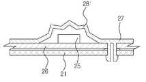
도광판(27)은 기판(26)에 대응하는 크기로 이루어지고 기판(26)의 전면에 결합된다. 도광판(27)의 전면에는 복수의 발광소자(25)에 대응하는 복수의 광가이드돌기(28)가 돌출 구비된다. 광가이드돌기(28)는 발광소자(25)에서 발생되는 빛을 특정 패턴으로 확산시켜서 도 5에 도시된 것과 같이, 하나의 발광소자(25)에서 발생되는 빛과 이와 인접하는 발광소자(25)에서 발생되는 빛의 중첩량을 증가시킨다. 따라서, 발광소자(25)에서 가까운 부분과 발광소자(25)에서 먼 부분 사이의 휘도차가 줄어들어 하나의 발광소자(25)와 인접하는 발광소자(25) 사이에 암부가 생기지 않는다. 그리고, 도광판(27)을 통과한 빛이 부분적으로 휘도차를 갖더라도 이러한 휘도차는 광학시트(23)를 통과하면서 더욱 감소됨으로써 표시패널(22)의 전면에는 휘선이 나타나지 않는다.The
각 광가이드돌기(28)의 후면 쪽에는 발광소자(25)를 수용하기 위한 수용홈(27a)이 구비된다. 도광판(27)이 기판(26)에 결합되면 도 3에 도시된 것과 같이, 각 발광소자(25)는 이에 대응하는 수용홈(27a)에 수용된다.The rear side of each
본 발명에 있어서, 광가이드돌기(28)의 형상은 도 3 및 도 4에 도시된 것과 같이, 상부 중앙이 오목하게 패인 원뿔 형상으로 한정되는 것은 아니다. 도 6 및 도 7은 광가이드돌기의 다양한 형태를 나타낸 것이다. 도 6에 도시된 광가이드돌기(28')는 표시패널(22;도 3참조)을 향해 다소 돌출된 원뿔 형상으로 이루어진 것이고, 도 7에 도시된 광가이드돌기(28")는 표시패널(22)을 향해 이중으로 돌출된 원뿔 형상으로 이루어진 것이다. 이러한 실시예 이외에도 광가이드돌기의 형상은 다양하게 변경될 수 있다.In the present invention, the shape of the
도광판(27)의 후면에는 베이스샤시(21)의 고정홀(21a) 및 기판(26)의 고정홀(26a)에 대응하는 복수의 고정돌기(29)가 돌출 구비된다. 복수의 고정돌기(29)는 도광판(27)과 기판(26)을 베이스샤시(21)에 한꺼번에 결합시키기 위한 고정부재로 작용한다. 즉, 복수의 고정돌기(29)가 기판(26)의 고정홀(26a)을 관통하여 베이스샤시(21)의 고정홀(21a)에 삽입됨으로써 베이스샤시(21) 위에 기판(26) 및 도광판(27)이 차례로 결합된다. 고정돌기(29)의 끝단은 다소 확장되어 있어서 베이스샤시(21)의 고정홀(21a)에 삽입된 고정돌기(29)는 고정홀(21a)에서 쉽게 벗어날 수 없다.A plurality of fixing
이와 같이 본 발명에 의한 평판표시장치(20)는 도광판(27)의 고정돌기(29)를 기판(26)의 고정홀(26a) 및 베이스샤시(21)의 고정홀(21a)에 차례로 삽입함으로써 백라이트유닛(24)을 베이스샤시(21)에 결합할 수 있다. 따라서, 나사를 이용하는 종래에 비해 조립이 매우 용이하다.As described above, the flat
또한, 본 발명에 의한 평판표시장치(20)는 도광판(27)이 복수의 발광소자(25)에서 발생되는 빛을 발산시켜 어느 정도 균일한 빛으로 변화시키기 때문에, 표시패널(22)과 복수의 발광소자(25) 사이의 거리를 좁히더라도 표시패널(22)의 전면에 휘선이 생기는 것을 막을 수 있다. 따라서, 종래에 비해 평판표시장치(20)의 두께를 줄일 수 있다.In addition, in the flat
한편, 도 8은 본 발명의 다른 실시예에 의한 평판표시장치(30)를 개략적으로 나타낸 측단면도이다.8 is a side cross-sectional view schematically showing a flat
도 8에 도시된 것과 같이, 본 발명의 다른 실시예에 의한 평판표시장치(30)는 베이스샤시(31)와, 표시패널(32)과, 표시패널(32)의 후면 쪽에 설치되는 광학시트(33)와, 표시패널(32)에 빛을 조사하기 위해 베이스샤시(31)에 결합되는 백라이트유닛(34)을 포함한다. 백라이트유닛(34)은 복수의 발광소자(35)가 일정한 간격으로 설치되는 기판(36)과, 복수의 발광소자(35)를 덮도록 기판(36)에 결합되는 도광판(37)을 포함한다.As shown in FIG. 8, the flat
이러한 본 실시예에 의한 평판표시장치(30)는 베이스샤시(31)와, 기판(36)과, 도광판(37)을 한꺼번에 결합하기 위한 고정부재가 상기 일실시예에 의한 평판표시장치(20)의 고정부재와 다른 것으로, 나머지 대부분의 구성은 상기 일실시예에 의한 평판표시장치(20)와 같다.The flat
베이스샤시(31)의 전면에는 복수의 고정돌기(39)가 돌출 구비되고, 기판(36) 및 도광판(37)에는 복수 고정돌기(39)에 대응하는 복수의 고정홀(36a)(37a)이 각각 구비된다. 베이스샤시(31)의 전면에 기판(36) 및 도광판(37)이 차례로 놓이고 고정돌기(39)가 기판(36)의 고정홀(36a)을 관통하여 도광판(37)의 고정홀(37a)에 삽입됨으로써, 베이스샤시(31)와, 기판(36)과, 도광판(37)은 한꺼번에 결합된다. 따라서, 본 실시예에 의한 평판표시장치(30)는 나사를 이용하여 기판(36)을 베이스샤시(31)에 결합하는 종래 평판표시장치(30)에 비해 조립이 용이하다.A plurality of fixing
또한, 본 실시예에 의한 평판표시장치(30)는 도광판(37)이 발광소자(35)에서 발생되는 빛을 발산시켜 균일한 빛으로 변화시키기 때문에, 표시패널(32)과 복수의 발광소자(35) 사이의 거리를 좁히더라도 표시패널(32)의 전면에 휘선이 나타나지 않는다. 따라서, 평판표시장치(30)의 두께를 종래에 비해 줄일 수 있다.In the flat
한편, 도 9는 본 발명의 또다른 실시예에 의한 평판표시장치(40)를 개략적으로 나타낸 단면도이다.9 is a schematic cross-sectional view of a
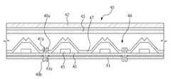
도 9에 도시된 본 발명의 또다른 실시예에 의한 평판표시장치(40)는 베이스샤시(41)와, 표시패널(42)과, 표시패널(42)의 후면 쪽에 설치되는 광학시트(43)와, 표시패널(42)에 빛을 조사하기 위해 베이스샤시(41)에 결합되는 백라이트유닛(44)을 포함한다. 백라이트유닛(44)은 복수의 발광소자(45)가 일정한 간격으로 설치되는 기판(46)과, 복수의 발광소자(45)를 덮도록 기판(46)에 결합되는 도광판(47)을 포함한다.A flat
본 실시예에 의한 평판표시장치(40) 역시 도 8에 도시된 평판표시장치(30)와 같이, 베이스샤시(41)와, 기판(46)과, 도광판(47)을 한꺼번에 결합시키기 위한 고정부재가 상기 일실시예에 의한 평판표시장치(20)와 다른 것으로, 나머지 대부분의 구성은 상기 일실시예에 의한 평판표시장치(20)와 같다.The flat
기판(46)에는 전면 및 후면 쪽으로 돌출되는 복수의 고정돌기(48a)(48b)가 구비된다. 복수의 고정돌기(48a)(48b)는 도광판(47)과 결합되는 제 1 돌기(48a)와, 베이스샤시(41)와 결합되는 제 2 돌기(48b)이다. 도광판(47)에는 복수의 제 1 돌기(48a)에 대응하는 복수의 고정홀(47a)이 구비되고, 베이스샤시(41)에는 복수의 제 2 돌기(48b)에 대응하는 복수의 고정홀(41a)이 구비된다. 평판표시장치(40)의 조립시 기판(46)의 제 1 돌기(48a)가 도광판(47)의 고정홀(47a)에 삽입되고, 제 2 돌기(48b)가 베이스샤시(41)의 고정홀(41a)에 삽입됨으로써 베이스샤시(41)와, 기판(46)과, 도광판(47)은 한꺼번에 결합된다.The
이러한 본 실시예에 의한 평판표시장치(40) 역시 상기 두 실시예에 의한 평판표시장치(20)(30)와 같은 장점을 가지고 있다. 즉, 본 실시예에 의한 평판표시장치(40)는 종래 평판표시장치(10)에 비해 조립이 용이하고, 복수의 발광소자(45)에서 발생되는 빛을 균일하게 변화시키는 도광판(47) 때문에 표시패널(42)과 복수의 발광소자(45) 사이의 거리를 좁힐 수 있다. The flat
이상에서 설명한 본 발명에 의한 평판표시장치는 영상신호에 따라 영상을 표시하는 액정표시장치나, 정지된 화상을 표시하는 광고판에 이용될 수 있다.The flat panel display device according to the present invention described above can be used for a liquid crystal display device for displaying an image according to an image signal, or for a billboard for displaying a still image.
도 1은 종래 평판표시장치를 개략적으로 나타낸 단면도이다.1 is a schematic cross-sectional view of a conventional flat panel display device.
도 2는 도 1에 도시된 종래 평판표시장치에 구비된 백라이트유닛에서 발생되는 빛의 발산 패턴을 개략적으로 나타낸 평면도이다.FIG. 2 is a plan view schematically illustrating a light emission pattern of the backlight unit included in the conventional flat panel display shown in FIG. 1.
도 3은 본 발명의 일실시예에 의한 평판표시장치를 개략적으로 나타낸 단면도이다.3 is a schematic cross-sectional view of a flat panel display device according to an exemplary embodiment of the present invention.
도 4는 도 3에 도시된 평판표시장치의 백라이트유닛을 개략적으로 나타낸 분해사시도이다.4 is an exploded perspective view schematically illustrating a backlight unit of the flat panel display of FIG. 3.
도 5는 도 4에 도시된 백라이트유닛에서 발생되는 빛의 발산 패턴을 개략적으로 나타낸 평면도이다.FIG. 5 is a plan view schematically illustrating a light emission pattern generated in the backlight unit illustrated in FIG. 4.
도 6 및 도 7은 본 발명에 의한 평판표시장치의 도광판에 구비되는 광가이드돌기의 다양한 형태를 나타낸 단면도이다.6 and 7 are cross-sectional views illustrating various forms of the light guide protrusions provided in the light guide plate of the flat panel display according to the present invention.
도 8은 본 발명의 다른 실시예에 의한 평판표시장치를 개략적으로 나타낸 단면도이다.8 is a schematic cross-sectional view of a flat panel display device according to another exemplary embodiment of the present invention.
도 9는 본 발명의 또다른 실시예에 의한 평판표시장치를 개략적으로 나타낸 단면도이다.9 is a schematic cross-sectional view of a flat panel display device according to still another exemplary embodiment of the present invention.
<도면의 주요부분에 대한 부호 설명><Description of Signs of Major Parts of Drawings>
20,30,40...평판표시장치21,31,41...베이스샤시20, 30, 40 ...
22,32,42...표시패널23,33,43...광학시트22,32,42
24,34,44...백라이트유닛25,35,45...발광소자24, 34, 44 ...
26,36,46...기판27,37,47...도광판26,36,46 ...
28,38...광가이드돌기29,39,48a,48b...고정돌기28,38 ...
Claims (10)
Translated fromKoreanPriority Applications (6)
| Application Number | Priority Date | Filing Date | Title |
|---|---|---|---|
| KR1020070124209AKR20090057573A (en) | 2007-12-03 | 2007-12-03 | Backlight unit and flat panel display device having the same |
| EP08778480.7AEP2215520B1 (en) | 2007-12-03 | 2008-06-30 | Flat panel display provided with direct backlight unit |
| PCT/KR2008/003815WO2009072718A1 (en) | 2007-12-03 | 2008-06-30 | Backlight unit and flat panel display having the same |
| US12/172,394US7843528B2 (en) | 2007-12-03 | 2008-07-14 | Backlight unit and flat panel display having the same |
| MX2008009029AMX2008009029A (en) | 2007-12-03 | 2008-07-14 | Back light unit and flat panel display apparatus . |
| CN2008101325185ACN101452139B (en) | 2007-12-03 | 2008-07-15 | Backlight unit and flat panel display having the same |
Applications Claiming Priority (1)
| Application Number | Priority Date | Filing Date | Title |
|---|---|---|---|
| KR1020070124209AKR20090057573A (en) | 2007-12-03 | 2007-12-03 | Backlight unit and flat panel display device having the same |
Publications (1)
| Publication Number | Publication Date |
|---|---|
| KR20090057573Atrue KR20090057573A (en) | 2009-06-08 |
Family
ID=40675345
Family Applications (1)
| Application Number | Title | Priority Date | Filing Date |
|---|---|---|---|
| KR1020070124209AAbandonedKR20090057573A (en) | 2007-12-03 | 2007-12-03 | Backlight unit and flat panel display device having the same |
Country Status (6)
| Country | Link |
|---|---|
| US (1) | US7843528B2 (en) |
| EP (1) | EP2215520B1 (en) |
| KR (1) | KR20090057573A (en) |
| CN (1) | CN101452139B (en) |
| MX (1) | MX2008009029A (en) |
| WO (1) | WO2009072718A1 (en) |
Cited By (2)
| Publication number | Priority date | Publication date | Assignee | Title |
|---|---|---|---|---|
| US8582051B2 (en) | 2010-06-15 | 2013-11-12 | Lg Innotek Co., Ltd. | Backlight unit and the display device having the same |
| CN113805380A (en)* | 2020-06-15 | 2021-12-17 | 夏普株式会社 | Display device |
Families Citing this family (20)
| Publication number | Priority date | Publication date | Assignee | Title |
|---|---|---|---|---|
| WO2008015831A1 (en)* | 2006-08-03 | 2008-02-07 | Sharp Kabushiki Kaisha | Illumination device for display device and display device with the same |
| KR101471945B1 (en)* | 2008-10-01 | 2014-12-12 | 삼성디스플레이 주식회사 | Backlight assembly |
| JP4621799B1 (en) | 2009-05-22 | 2011-01-26 | シャープ株式会社 | Light reflecting sheet, light source device and display device |
| JP5351723B2 (en) | 2009-05-22 | 2013-11-27 | シャープ株式会社 | Light source device and display device |
| JP4519944B1 (en)* | 2009-05-22 | 2010-08-04 | シャープ株式会社 | Light source device and display device |
| CN102803823B (en)* | 2009-06-15 | 2015-09-23 | 夏普株式会社 | Lighting device, display unit and radiovisor |
| US8313206B2 (en)* | 2009-12-15 | 2012-11-20 | Ing Wen-Chiun | Lighting device |
| US20130148332A1 (en)* | 2010-09-15 | 2013-06-13 | Sharp Kabushiki Kaisha | Illumination device and display device |
| US8678603B2 (en)* | 2011-03-29 | 2014-03-25 | Shenzhen China Star Optoelectronics Technology Co., Ltd. | Backlight module having elastic holder and liquid crystal display employing same |
| KR20130046042A (en)* | 2011-10-27 | 2013-05-07 | 삼성전자주식회사 | Backlight unit and display apparatus having the same |
| CN102401334B (en)* | 2011-11-18 | 2013-11-27 | 深圳市华星光电技术有限公司 | Back frame of flat panel display device and backlight system |
| CN102759052B (en)* | 2012-07-19 | 2014-12-17 | 深圳市华星光电技术有限公司 | Backlight module and display device |
| TW201426036A (en)* | 2012-12-24 | 2014-07-01 | Radiant Opto Electronics Corp | Light guide element and light source using the same |
| US9575237B2 (en) | 2012-12-24 | 2017-02-21 | Radiant Opto-Electronics Corporation | Light guide element and light source device using the light guide element |
| US9733401B2 (en)* | 2013-03-14 | 2017-08-15 | Leyard Optoelectronic Co., Ltd. | LED display system |
| KR102130524B1 (en)* | 2013-08-28 | 2020-07-07 | 삼성디스플레이 주식회사 | Light emitting module, backlight unit comprising the same and liquid crystal display comprising the same |
| TWI567460B (en)* | 2015-12-11 | 2017-01-21 | 友達光電股份有限公司 | Backlight module |
| JP2020056868A (en)* | 2018-10-01 | 2020-04-09 | 株式会社エンプラス | Luminous flux control member, light-emitting device, surface light source device, and display device |
| JP7265459B2 (en)* | 2019-09-26 | 2023-04-26 | シャープ株式会社 | Lighting device and display device |
| TWI710837B (en)* | 2019-11-21 | 2020-11-21 | 友達光電股份有限公司 | Backlight module |
Family Cites Families (14)
| Publication number | Priority date | Publication date | Assignee | Title |
|---|---|---|---|---|
| US5727862A (en)* | 1996-11-25 | 1998-03-17 | Taiwan Liton Electronic Co., Ltd. | LED back light assembly |
| JP3728981B2 (en)* | 1998-08-26 | 2005-12-21 | セイコーエプソン株式会社 | Liquid crystal device and electronic device |
| JP2004184493A (en)* | 2002-11-29 | 2004-07-02 | Seiko Epson Corp | Electro-optical device, method of manufacturing electro-optical device, and electronic apparatus |
| JP2005228606A (en)* | 2004-02-13 | 2005-08-25 | Nippon Seiki Co Ltd | Lighting device |
| TWM268608U (en)* | 2004-12-10 | 2005-06-21 | Innolux Display Corp | Back light module |
| TWI317829B (en) | 2004-12-15 | 2009-12-01 | Epistar Corp | Led illumination device and application thereof |
| WO2006098114A1 (en)* | 2005-03-15 | 2006-09-21 | Sharp Kabushiki Kaisha | Display and television receiver equipped with the display |
| KR101098338B1 (en)* | 2005-04-22 | 2011-12-26 | 삼성전자주식회사 | Optic package, optic lens and backlight assembly and display device having the optic package |
| JP4600257B2 (en)* | 2005-11-25 | 2010-12-15 | ソニー株式会社 | Light guide plate, backlight device, manufacturing method thereof, and liquid crystal display device |
| KR100790697B1 (en)* | 2006-02-21 | 2008-01-02 | 삼성전기주식회사 | LED backlight unit |
| KR101395059B1 (en)* | 2007-11-29 | 2014-05-14 | 삼성디스플레이 주식회사 | Backlight unit and liquid crystal display having the same |
| CN101464596B (en)* | 2007-12-21 | 2012-02-01 | 鸿富锦精密工业(深圳)有限公司 | Optical board and backlight module |
| KR101421626B1 (en)* | 2008-01-09 | 2014-07-22 | 삼성디스플레이 주식회사 | Light source unit and backlight unit and liquid crystal display having the same |
| US20090201441A1 (en)* | 2008-02-13 | 2009-08-13 | Rohm And Haas Electronic Materials Llc | Tensioned optical element having crimping frame and spring |
- 2007
- 2007-12-03KRKR1020070124209Apatent/KR20090057573A/ennot_activeAbandoned
- 2008
- 2008-06-30WOPCT/KR2008/003815patent/WO2009072718A1/ennot_activeCeased
- 2008-06-30EPEP08778480.7Apatent/EP2215520B1/ennot_activeNot-in-force
- 2008-07-14MXMX2008009029Apatent/MX2008009029A/enactiveIP Right Grant
- 2008-07-14USUS12/172,394patent/US7843528B2/enactiveActive
- 2008-07-15CNCN2008101325185Apatent/CN101452139B/ennot_activeExpired - Fee Related
Cited By (2)
| Publication number | Priority date | Publication date | Assignee | Title |
|---|---|---|---|---|
| US8582051B2 (en) | 2010-06-15 | 2013-11-12 | Lg Innotek Co., Ltd. | Backlight unit and the display device having the same |
| CN113805380A (en)* | 2020-06-15 | 2021-12-17 | 夏普株式会社 | Display device |
Also Published As
| Publication number | Publication date |
|---|---|
| EP2215520A4 (en) | 2011-01-26 |
| US20090141208A1 (en) | 2009-06-04 |
| WO2009072718A1 (en) | 2009-06-11 |
| US7843528B2 (en) | 2010-11-30 |
| MX2008009029A (en) | 2009-06-16 |
| EP2215520A1 (en) | 2010-08-11 |
| EP2215520B1 (en) | 2016-03-30 |
| CN101452139A (en) | 2009-06-10 |
| CN101452139B (en) | 2011-08-17 |
Similar Documents
| Publication | Publication Date | Title |
|---|---|---|
| KR20090057573A (en) | Backlight unit and flat panel display device having the same | |
| KR101279126B1 (en) | Backlight unit and liquid crystal display device using the same | |
| TWI396150B (en) | Display device | |
| CN102879951B (en) | Display device, electronic equipment and illuminator | |
| KR101671182B1 (en) | A backlight unit and an lcd module having the same | |
| KR101648619B1 (en) | Frame for display device and deisplay device having the same | |
| KR20060000977A (en) | Backlight Unit of LCD | |
| WO2011093119A1 (en) | Illuminating device, display device, and television receiver | |
| KR20080041421A (en) | Backlight unit and liquid crystal display including the same | |
| WO2010146920A1 (en) | Illumination device, display device, and television receiver | |
| KR20090008749U (en) | Side light type led lightening device having auxiliary led in direct type for auxiliary display | |
| KR20070077268A (en) | Back light assembly and liquid crystal display device having the same | |
| KR20120030909A (en) | Backlgiht unit and liquid crystal display device the same | |
| US20060221632A1 (en) | Signboard using LED light source | |
| WO2012053442A1 (en) | Lighting device and display device | |
| CN101910711A (en) | Illuminating device, display device and television receiver | |
| WO2012050052A1 (en) | Backlight unit and liquid crystal display device | |
| KR20060010224A (en) | Back light assembly and display device having same | |
| US7990492B2 (en) | Liquid crystal display and display device with light source assembly | |
| KR20090053631A (en) | Backlight unit, LCD having same and manufacturing method thereof | |
| KR101337176B1 (en) | Edge type lighting device for improving hot spot | |
| KR20080030801A (en) | Backlight assembly | |
| KR20120066338A (en) | A panel mounting structure of backlight unit | |
| KR101441681B1 (en) | Display apparatus for electronic device | |
| JP2009104197A (en) | Light source structure of internal illumination type bulletin apparatus |
Legal Events
| Date | Code | Title | Description |
|---|---|---|---|
| PA0109 | Patent application | Patent event code:PA01091R01D Comment text:Patent Application Patent event date:20071203 | |
| PG1501 | Laying open of application | ||
| A201 | Request for examination | ||
| PA0201 | Request for examination | Patent event code:PA02012R01D Patent event date:20121203 Comment text:Request for Examination of Application Patent event code:PA02011R01I Patent event date:20071203 Comment text:Patent Application | |
| E902 | Notification of reason for refusal | ||
| PE0902 | Notice of grounds for rejection | Comment text:Notification of reason for refusal Patent event date:20140128 Patent event code:PE09021S01D | |
| E701 | Decision to grant or registration of patent right | ||
| PE0701 | Decision of registration | Patent event code:PE07011S01D Comment text:Decision to Grant Registration Patent event date:20140516 | |
| PC1904 | Unpaid initial registration fee |