KR20090055416A - Medical Suction Catheter - Google Patents
Medical Suction CatheterDownload PDFInfo
- Publication number
- KR20090055416A KR20090055416AKR1020070122331AKR20070122331AKR20090055416AKR 20090055416 AKR20090055416 AKR 20090055416AKR 1020070122331 AKR1020070122331 AKR 1020070122331AKR 20070122331 AKR20070122331 AKR 20070122331AKR 20090055416 AKR20090055416 AKR 20090055416A
- Authority
- KR
- South Korea
- Prior art keywords
- suction
- optical waveguide
- suction tube
- coupling
- medical
- Prior art date
- Legal status (The legal status is an assumption and is not a legal conclusion. Google has not performed a legal analysis and makes no representation as to the accuracy of the status listed.)
- Ceased
Links
Images


Classifications
- A—HUMAN NECESSITIES
- A61—MEDICAL OR VETERINARY SCIENCE; HYGIENE
- A61M—DEVICES FOR INTRODUCING MEDIA INTO, OR ONTO, THE BODY; DEVICES FOR TRANSDUCING BODY MEDIA OR FOR TAKING MEDIA FROM THE BODY; DEVICES FOR PRODUCING OR ENDING SLEEP OR STUPOR
- A61M25/00—Catheters; Hollow probes
- A61M25/0009—Making of catheters or other medical or surgical tubes
- A—HUMAN NECESSITIES
- A61—MEDICAL OR VETERINARY SCIENCE; HYGIENE
- A61M—DEVICES FOR INTRODUCING MEDIA INTO, OR ONTO, THE BODY; DEVICES FOR TRANSDUCING BODY MEDIA OR FOR TAKING MEDIA FROM THE BODY; DEVICES FOR PRODUCING OR ENDING SLEEP OR STUPOR
- A61M25/00—Catheters; Hollow probes
- A—HUMAN NECESSITIES
- A61—MEDICAL OR VETERINARY SCIENCE; HYGIENE
- A61B—DIAGNOSIS; SURGERY; IDENTIFICATION
- A61B1/00—Instruments for performing medical examinations of the interior of cavities or tubes of the body by visual or photographical inspection, e.g. endoscopes; Illuminating arrangements therefor
- A61B1/00131—Accessories for endoscopes
- A61B1/0014—Fastening element for attaching accessories to the outside of an endoscope, e.g. clips, clamps or bands
- A—HUMAN NECESSITIES
- A61—MEDICAL OR VETERINARY SCIENCE; HYGIENE
- A61B—DIAGNOSIS; SURGERY; IDENTIFICATION
- A61B1/00—Instruments for performing medical examinations of the interior of cavities or tubes of the body by visual or photographical inspection, e.g. endoscopes; Illuminating arrangements therefor
- A61B1/012—Instruments for performing medical examinations of the interior of cavities or tubes of the body by visual or photographical inspection, e.g. endoscopes; Illuminating arrangements therefor characterised by internal passages or accessories therefor
- A61B1/015—Control of fluid supply or evacuation
- A—HUMAN NECESSITIES
- A61—MEDICAL OR VETERINARY SCIENCE; HYGIENE
- A61B—DIAGNOSIS; SURGERY; IDENTIFICATION
- A61B1/00—Instruments for performing medical examinations of the interior of cavities or tubes of the body by visual or photographical inspection, e.g. endoscopes; Illuminating arrangements therefor
- A61B1/12—Instruments for performing medical examinations of the interior of cavities or tubes of the body by visual or photographical inspection, e.g. endoscopes; Illuminating arrangements therefor with cooling or rinsing arrangements
- A61B1/121—Instruments for performing medical examinations of the interior of cavities or tubes of the body by visual or photographical inspection, e.g. endoscopes; Illuminating arrangements therefor with cooling or rinsing arrangements provided with means for cleaning post-use
- A—HUMAN NECESSITIES
- A61—MEDICAL OR VETERINARY SCIENCE; HYGIENE
- A61M—DEVICES FOR INTRODUCING MEDIA INTO, OR ONTO, THE BODY; DEVICES FOR TRANSDUCING BODY MEDIA OR FOR TAKING MEDIA FROM THE BODY; DEVICES FOR PRODUCING OR ENDING SLEEP OR STUPOR
- A61M25/00—Catheters; Hollow probes
- A61M25/0021—Catheters; Hollow probes characterised by the form of the tubing
- A61M25/0041—Catheters; Hollow probes characterised by the form of the tubing pre-formed, e.g. specially adapted to fit with the anatomy of body channels
- A—HUMAN NECESSITIES
- A61—MEDICAL OR VETERINARY SCIENCE; HYGIENE
- A61M—DEVICES FOR INTRODUCING MEDIA INTO, OR ONTO, THE BODY; DEVICES FOR TRANSDUCING BODY MEDIA OR FOR TAKING MEDIA FROM THE BODY; DEVICES FOR PRODUCING OR ENDING SLEEP OR STUPOR
- A61M25/00—Catheters; Hollow probes
- A61M25/01—Introducing, guiding, advancing, emplacing or holding catheters
- A61M25/02—Holding devices, e.g. on the body
Landscapes
- Health & Medical Sciences (AREA)
- Life Sciences & Earth Sciences (AREA)
- Biophysics (AREA)
- Pulmonology (AREA)
- Engineering & Computer Science (AREA)
- Anesthesiology (AREA)
- Biomedical Technology (AREA)
- Heart & Thoracic Surgery (AREA)
- Hematology (AREA)
- Animal Behavior & Ethology (AREA)
- General Health & Medical Sciences (AREA)
- Public Health (AREA)
- Veterinary Medicine (AREA)
- External Artificial Organs (AREA)
Abstract
Translated fromKoreanDescription
Translated fromKorean본 발명은 의료용 석션 카테터에 관한 것으로, 보다 상세하게는 석션관이 광도파관에 착탈가능하게 분리되는 구조를 가져 세척 및 소독이 용이할 뿐만 아니라 사용된 석션관을 폐기하고 새로운 석션관으로 교체할 수 있는 의료용 석션 카테터에 관한 것이다.The present invention relates to a medical suction catheter, and more particularly has a structure in which the suction tube is detachably detachable from the optical waveguide to facilitate the cleaning and disinfection, as well as to discard the used suction tube and replace it with a new suction tube. A medical suction catheter.
석션(Suction)장비는 수술실에서 사용하는 장비로서 수술시 발생하는 환자의 혈액이나 수액, 농 및 기타 오물을 진공장치로 흡인 후 제거하는 장비를 말한다.Suction equipment is a device used in the operating room and refers to a device that suctions and removes blood, sap, pus and other debris from a patient during surgery.
통상 상기 석션장비는 이물질 및 기타 오물을 흡인하고 세척과 소독 그리고 세균감염에 잘 저항되도록 구성된 석션용기(suction jar)와, 상기 석션용기에 흡인력을 부가하는 압축기로 구성된 흡입장치와, 시술되는 부위의 오물을 흡입하기 위한 석션관이 구비되어 시술되는 부위에 용이하게 근접시킬 수 있도록 구성된 석션 카테터(suction catheter)와, 상기 석션용기와 상기 석션 카테터를 연결하는 석션호스로 구성된다.In general, the suction equipment includes a suction jar configured to suck foreign substances and other dirt, and to be well-resistant to washing, disinfection and bacterial infection, a suction device including a compressor for adding suction to the suction container, and It is composed of a suction catheter provided with a suction tube for suctioning dirt, and a suction hose connecting the suction container and the suction catheter.
그런데, 석션장비의 사용시 수술대의 조명장치 만으로는 흡입부위를 정확하게 판별하기가 힘들다. 따라서, 상기와 같은 석션 카테터에는 일정한 조도의 광을 출사시키는 광원으로부터 빛을 시술되는 부위에 조사하는 광도파관이 상기 시술부위에서 발생되는 각종 이물질을 흡입하는 석션관과 함께 구비된다. 대한민국 공개특허 제10-2005-0117277호에는 광도파관과 석션관이 일체로 결합된 석션 카테터가 개시되어 있으며, 도 5는 이를 도시한 것이다. 도면을 참조하면, 대한민국 공개특허 제10-2005-0117277호에 개시된 석션 카테터는 석션관(2)의 일측에 도파관(1)이 나란하게 결합되고 상기 석션관(2)과 광도파관(1)이 손잡이(3)에 의해 일체로 결합되게 구성된다. 도 5의 번호 4는 석션관(2)의 개폐 스위치이다.However, when using the suction equipment, it is difficult to accurately determine the inhalation site only with the lighting device of the operating table. Therefore, the suction catheter as described above is provided with an optical waveguide for irradiating light to a site to be treated from a light source that emits light of constant illuminance together with a suction tube for sucking various foreign substances generated at the procedure site. Korean Patent Laid-Open Publication No. 10-2005-0117277 discloses a suction catheter in which an optical waveguide and a suction tube are integrally coupled, and FIG. 5 illustrates this. Referring to the drawings, the suction catheter disclosed in Korean Patent Laid-Open Publication No. 10-2005-0117277 has a
통상 의료용 석션 카테터의 경우에는 환자가 바뀌거나 재사용시 세척과 소독이 이루어져야 한다. 특히 석션관을 통해 환자의 오물이 흡입되기 때문에 석션관의 구멍 내부를 세척 및 살균이 매우 중요하다.Medical suction catheters typically require cleaning and disinfection when changing patients or reusing. In particular, since the suction of the patient is sucked through the suction tube, it is very important to clean and sterilize the inside of the suction tube.
그런데 상기와 같은 의료용 석션 카테터의 경우 석션관이 광도파관과 분리되지 않게 결합된 구조이기 때문에 카테터를 세척하고 소독하는 작업은 매우 번거롭다. 예를 들면, 광도파관의 경우 열에 약하기 때문에 소독을 위해 카테터에 고열을 가할 수 없는 한계를 갖는다.However, in the case of the medical suction catheter as described above, since the suction tube is not separated from the optical waveguide, it is very troublesome to clean and disinfect the catheter. For example, optical waveguides have a limitation in that they cannot be subjected to high temperatures in the catheter for disinfection because they are weak in heat.
또한, 석션관이 광도파관에 결합된 상태에서 석션관의 구멍을 세척하고 살균하는 작업은 매우 어렵다.In addition, it is very difficult to clean and sterilize the holes of the suction tube while the suction tube is coupled to the optical waveguide.
더욱이, 종래의 의료용 석션 카테터의 경우 석션관이 광도파관에 분리되지 않게 결합된 구조이기 때문에 석션관이 반드시 재사용되게 되고, 만일 세척 및 살균이 충분하게 이루어지지 않는 경우에 감염의 우려가 매우 높다.Moreover, in the case of the conventional medical suction catheter, the suction tube is necessarily reused because the suction tube is not separated from the optical waveguide, and the suction tube is necessarily reused.
본 발명은 상기와 같은 점을 인식하여 안출된 것으로, 본 발명의 목적은 석션관이 광도파관에 착탈가능하게 분리되는 구조를 가져 세척 및 소독이 용이할 뿐만 아니라 사용된 석션관을 폐기하고 새로운 석션관으로 교체할 수 있는 의료용 석션 카테터를 제공하기 위한 것이다.The present invention has been made in view of the above, the object of the present invention has a structure in which the suction tube detachably detachable from the optical waveguide, easy to clean and disinfect, as well as discard the used suction tube and new suction To provide a medical suction catheter that can be replaced with a tube.
상기와 같은 목적을 달성하기 위하여 본 발명에 따른 의료용 석션 카테터는, 후단입사부를 통해 입력된 빛이 선단조사부를 통해 전방으로 조사되도록 길게 연장형성된 광도파관과, 후단연결부에 석션호스가 연결되고 선단흡입부가 시술부위에 근접되게 길게 형성되어 상기 광도파관과 겹쳐지게 나란하게 포개져 그 광도파관과 일체로 결합되는 석션관과, 상기 석션관을 상기 광도파관에 분리 가능하게 연결하기 위한 결합수단을 포함하여 구성된 것을 특징으로 한다.In order to achieve the above object, the medical suction catheter according to the present invention includes an optical waveguide extending in a long way so that light input through the rear end incident part is irradiated forward through the front end irradiation part, and a suction hose is connected to the rear end connection part and the front suction And a suction tube which is formed to be prolonged adjacent to the additional surgical part and overlaps with the optical waveguide so as to overlap the optical waveguide and is integrally coupled with the optical waveguide, and coupling means for detachably connecting the suction tube to the optical waveguide. Characterized in that configured.
또한, 본 발명에 따른 의료용 석션 카테터는, 상기 결합수단은, 상기 결합수단은, 상기 석션관 상부에 탄성을 갖는 결합블레이드 한 쌍이 서로 마주보며 길이방향으로 길게 형성되어 그 한 쌍의 결합블레이드 사이에 상방으로 열린 결합홈이 형성되고, 상기 광도파관은 상기 결합홈에 삽입되어 상기 결합블레이드에 물리도록 구성된 것을 특징으로 한다.In addition, the medical suction catheter according to the present invention, the coupling means, the coupling means, a pair of coupling coupling blades having elasticity on the suction tube is formed long in the longitudinal direction facing each other between the pair of coupling blades The coupling groove is opened upward, the optical waveguide is inserted into the coupling groove is characterized in that it is configured to bite into the coupling blade.
상기와 같은 구성에 의하여 본 발명에 따른 의료용 석션 카테터는 석션관이 광도파관에 착탈가능하게 분리되는 구조를 가져 세척 및 소독이 용이할 뿐만 아니라 사용된 석션관을 폐기하고 새로운 석션관으로 교체할 수 있는 장점을 갖는다.By the above configuration, the medical suction catheter according to the present invention has a structure in which the suction tube is detachably detached from the optical waveguide, which is easy to clean and disinfect, as well as discard the used suction tube and replace it with a new suction tube. That has the advantage.
이하에서는 도면에 도시된 실시예를 참조하여 본 발명에 따른 의료용 석션 카테터를 보다 상세하게 설명하기로 한다.Hereinafter, a medical suction catheter according to the present invention will be described in more detail with reference to the embodiment shown in the drawings.
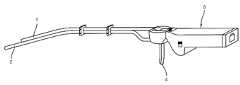
도 1은 본 발명의 일실시예에 따른 의료용 석션 카테터를 도시한 분해 사시도이고, 도 2는 본 발명의 일실시예에 따른 의료용 석션 카테터를 도시한 사시도이며, 도 3은 본 발명의 일실시예에 따른 의료용 석션 카테터를 도시한 측면도이다.1 is an exploded perspective view showing a medical suction catheter according to an embodiment of the present invention, Figure 2 is a perspective view showing a medical suction catheter according to an embodiment of the present invention, Figure 3 is an embodiment of the present invention Side view showing a medical suction catheter according to.
도면을 참조하면, 본 발명의 일실시예에 따른 의료용 석션 카테터는 광도파관(20), 석션관(10) 및 결합수단으로 구성된다.Referring to the drawings, the medical suction catheter according to an embodiment of the present invention is composed of an
상기 광도파관(20)은 상기 석션관(10)에 의해 오물을 흡입하고자 하는 시술부위를 조사하도록 소정의 광원(도면에 미도시)으로부터 발생된 빛을 전달하기 위한 것으로 관형상을 갖는다. 도면을 참조하면, 상기 광도파관(20)은 소정의 광원으로 연결된 후단입사부(22)를 통해 입력된 빛이 선단조사부(21)를 통해 전방으로 조사되도록 길게 관형상으로 연장형성된다. 상기 광도파관(20)의 내부에는 빛을 전달하기 위한 매질이 채워되는데, 통상 매질로는 광섬유가 사용된다. 상기 광도파관의 후단부 측에는 사용자가 손으로 잡을 수 있도록 파지돌출부(25)가 상방으로 돌출되어 소정길이를 갖도록 형성되는데, 상기 파지돌출부(25)의 상부에는 파지한 손의 엄지속가락이 안착되기 위한 손가락 안착홈(25a)가 형성된다. 한편, 사용자가 시술부위에 접근이 용이하도록 상기 광도파관(20) 및 이에 결합된 석션관(10)은 전체적으로 전단부 측에서 약간 굽어지는 형상을 갖는다. 즉, 상기 광도파관(20)의 전단부 측에는 약간 굽어진 제1만곡부(23)이 형성된다.The
상기 석션관(10)은 시술부위의 오물을 흡입하기 위한 관체로서 상기 광도파관(20)의 하부에 포개져 결합된다. 도면을 참조하면, 상기 석션관(10)은 전체적으로 상기 광도파관(20)에 포개지도록 상기 광도파관(20)에 대응되는 형상으로 길게 연장형성된다. 상기 석션관(10)은 후단연결부(12)에 석션호스(T)가 연결되며, 선단흡입부(11)가 시술부위에 근접되게 길게 형성된다. 상기 석션관(10)의 전단부 측에는 상기 광도파관(20)의 제1만곡부(23)에 대응되는 위치에서 상기 광도파관(20)의 제1만곡부(23)과 마찬가지로 약간 굽어지는 제1만곡부(13)이 형성된다. 또한, 상기 석션관(10)의 후단부 측에는 상기 후단흡입부(11)에 석션호스(T)를 빼고 끼우는 작업이 용이하도록 그 후단흡입부(11)가 상기 광도파관(20)과 떨어지도록 하방으로 약간 굽어지게 제2만곡부(24)가 형성된다. 상기와 같이 형성된 석션관(10)은 상기 광도파관(20)과 겹쳐지게 나란하게 포개져 상기 결합수단에 의해 광도파관(20)과 일체로 결합된다.The
상기 결합수단은 상기 석션관(10)을 상기 광도파관(20)에 분리 가능하게 연결하기 위한 것이다. 상기 결합수단은 상기 석션관(10)과 광도파관(20)이 서로 포개진 상태에서 이들을 서로 묶어주는 결속 밴드나 클립(도면에 미도시)과 같은 부재로 구성되어 질 수 있다. 도면에는 상기 결합수단으로 상기 석션관(10)의 상부에 그 길이방향을 따라 결합블레이드(15)가 형성된 실시예가 도시되어 있다. 도면을 참조하면, 상기 결합수단으로서 상기 결합블레이드(15)는 탄성을 가지며 상기 석션관(10) 상부에 한 쌍이 서로 마주보며 길이방향으로 길게 형성된다. 상기 결합블레이드(15)는 상기 석션관(10)의 선단흡입부(11)와 후단연결부(12) 사이에 형성된다. 상기 한 쌍의 결합블레이드(15) 사이에는 상방으로 열린 결합홈(15a)이 형성된다. 상기 석션관(10)은 상기 광도파관(20)이 상기 결합블레이드(15)에 물리도록 그 광도파고나(20)을 상기 결합홈(15a)에 삽입시켜 상기 광도파관(20)에 일체로 결합된다. 그리고, 상기 석션관(10)은 상기 광도파관(20)을 상기 결합홈(15a)로부터 빼냄으로써 광도파관(20)으로부터 분리된다.The coupling means is for detachably connecting the
한편, 상기와 같이 결합블레이드(15)가 형성된 석션관(10)은 상기 광도파관(20)으로부터 분리가 용이하게 되며, 이에 따라 상기 석션관(10)만을 분리하여 세척 및 소독이 가능해진다. 뿐만 아니라 사용한 석션관(10)을 제거하고 새로운 석션관을 상기 광도파관(20)에 결합시킬 수 있게 된다.Meanwhile, the
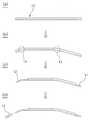
도 4는 본 발명의 일실시예에 따른 의료용 석션 카테터 중 석션관(10)의 제조 과정을 도시한 흐름도이다.Figure 4 is a flow chart showing the manufacturing process of the
도면을 참조하면, 상기와 같이 결합블레이드(15)가 형성된 석션관(10)은 무독성의 수지재질을 압출하여 결합블레이드(15)가 후단에서 선단까지 형성된 석션관 압출체(10')를 형성하고(a단계), 상기 석션관 압출체(10')를 만곡시켜 제1만곡부(13) 및 제2만곡부(14)를 형성하고(b단계), 만곡된 압출체(10')의 선단부와 후단부의 결합블레이드(15)를 제거하여 선단흡입부(11)와 후단가공부(12')를 가공함으로써 제작된다. 상기에서 b단계와 c단계는 순서가 바뀔 수 있는 과정이다. 상기 후단가공부(12')에는 석션호스(T)가 직접 끼워질 수 있는데, 그 경우 석션호스(T) 가 잘 빠지므로, 상기 후단가공부(12')에는 테이퍼 주름이 형성된 후단연결부(12)가 결합되는 것이 바람직하다(d단계).Referring to the drawings, the
앞에서 설명되고 도면에 도시된 의료용 석션 카테터는 본 발명을 실시하기 위한 하나의 실시예에 불과하며, 본 발명의 기술적 사상을 한정하는 것으로 해석되어서는 안된다. 본 발명의 보호범위는 이하의 특허청구범위에 기재된 사항에 의해서만 정하여지며, 본 고안의 요지를 벗어남이 없이 개량 및 변경된 실시예는 본 발명이 속하는 기술분야에서 통상의 지식을 가진 자에게 자명한 것인 한 본 발명의 보호범위에 속한다고 할 것이다.The medical suction catheter described and illustrated in the drawings is only one embodiment for carrying out the present invention, and should not be construed as limiting the technical spirit of the present invention. The scope of protection of the present invention is defined only by the matters set forth in the claims below, and the embodiments which are improved and changed without departing from the gist of the present invention are obvious to those skilled in the art. It will be said to belong to the protection scope of the present invention.
도 1은 본 발명의 일실시예에 따른 의료용 석션 카테터를 도시한 분해 사시도1 is an exploded perspective view showing a medical suction catheter according to an embodiment of the present invention
도 2는 본 발명의 일실시예에 따른 의료용 석션 카테터를 도시한 사시도Figure 2 is a perspective view of a medical suction catheter according to an embodiment of the present invention
도 3은 본 발명의 일실시예에 따른 의료용 석션 카테터를 도시한 측면도Figure 3 is a side view showing a medical suction catheter according to an embodiment of the present invention
도 4는 본 발명의 일실시예에 따른 의료용 석션 카테터의 제조 과정을 도시한 흐름도4 is a flowchart illustrating a manufacturing process of a medical suction catheter according to an embodiment of the present invention.
도 5는 종래의 의료용 석션 카테터를 도시한 측면도Figure 5 is a side view showing a conventional medical suction catheter
<주요 도면부호에 대한 간단한 설명><Short description of the major reference symbols>
10석션관10 suction tube
11선단흡입부 11 Tip Suction Part
12후단연결부 12 Rear connection
13제1만곡부 13 first bend
14제2만곡부 14 2nd bend
15결합블레이드 15 Combination Blade
15a결합홈 15a coupling groove
20광도파관20 light waveguide
21선단조사부 21 Tip Research Department
22후단입사부 22 Back Office
23제1만곡부 23 first bend
25파지돌출부 25 Gripping protrusion
25a손가락 안착홈 25a Finger Home
Claims (2)
Translated fromKoreanPriority Applications (2)
| Application Number | Priority Date | Filing Date | Title |
|---|---|---|---|
| KR1020070122331AKR20090055416A (en) | 2007-11-28 | 2007-11-28 | Medical Suction Catheter |
| PCT/KR2007/006075WO2009069837A1 (en) | 2007-11-28 | 2007-11-29 | Suction catheter for surgical |
Applications Claiming Priority (1)
| Application Number | Priority Date | Filing Date | Title |
|---|---|---|---|
| KR1020070122331AKR20090055416A (en) | 2007-11-28 | 2007-11-28 | Medical Suction Catheter |
Publications (1)
| Publication Number | Publication Date |
|---|---|
| KR20090055416Atrue KR20090055416A (en) | 2009-06-02 |
Family
ID=40678717
Family Applications (1)
| Application Number | Title | Priority Date | Filing Date |
|---|---|---|---|
| KR1020070122331ACeasedKR20090055416A (en) | 2007-11-28 | 2007-11-28 | Medical Suction Catheter |
Country Status (2)
| Country | Link |
|---|---|
| KR (1) | KR20090055416A (en) |
| WO (1) | WO2009069837A1 (en) |
Cited By (2)
| Publication number | Priority date | Publication date | Assignee | Title |
|---|---|---|---|---|
| KR101479284B1 (en)* | 2012-11-30 | 2015-01-06 | 주식회사 탑알앤디 | Suction catheter for surgical |
| KR20240077115A (en)* | 2022-11-24 | 2024-05-31 | 국립부경대학교 산학협력단 | Syringe Proximity Light-Based Disinfection Device |
Families Citing this family (4)
| Publication number | Priority date | Publication date | Assignee | Title |
|---|---|---|---|---|
| US8292805B2 (en) | 2009-11-10 | 2012-10-23 | Invuity, Inc. | Illuminated suction apparatus |
| US8795162B2 (en) | 2009-11-10 | 2014-08-05 | Invuity, Inc. | Illuminated suction apparatus |
| JP6317583B2 (en)* | 2010-12-16 | 2018-04-25 | インブイティ・インコーポレイテッド | Illuminated suction device |
| EP3473160B1 (en)* | 2012-12-12 | 2023-12-27 | Invuity, Inc. | Illuminated suction apparatus |
Family Cites Families (5)
| Publication number | Priority date | Publication date | Assignee | Title |
|---|---|---|---|---|
| US5643175A (en)* | 1992-09-01 | 1997-07-01 | Adair; Edwin L. | Sterilizable endoscope with separable disposable tube assembly |
| US5588952A (en)* | 1993-08-02 | 1996-12-31 | Dandolu; Bhaktavathsala R. | Intracardiac illuminator with suction |
| US6248061B1 (en)* | 1999-11-04 | 2001-06-19 | Lewis L. Cook, Jr. | Suctioning laryngoscope blade |
| KR100446717B1 (en)* | 2002-03-21 | 2004-09-01 | 정하철 | Suction borescope for medical treatment |
| KR100486152B1 (en)* | 2003-06-10 | 2005-04-29 | 주식회사 탑알앤디 | Optical suction catheter |
- 2007
- 2007-11-28KRKR1020070122331Apatent/KR20090055416A/ennot_activeCeased
- 2007-11-29WOPCT/KR2007/006075patent/WO2009069837A1/enactiveApplication Filing
Cited By (2)
| Publication number | Priority date | Publication date | Assignee | Title |
|---|---|---|---|---|
| KR101479284B1 (en)* | 2012-11-30 | 2015-01-06 | 주식회사 탑알앤디 | Suction catheter for surgical |
| KR20240077115A (en)* | 2022-11-24 | 2024-05-31 | 국립부경대학교 산학협력단 | Syringe Proximity Light-Based Disinfection Device |
Also Published As
| Publication number | Publication date |
|---|---|
| WO2009069837A1 (en) | 2009-06-04 |
Similar Documents
| Publication | Publication Date | Title |
|---|---|---|
| KR20090055416A (en) | Medical Suction Catheter | |
| CA2805380C (en) | Suction device for evacuating fumes | |
| KR20040010630A (en) | Medical rinsing and sucking device | |
| US11305049B2 (en) | Suction instrument with varying inner diameter | |
| JP2014515644A (en) | Self-cleaning surgical suction device | |
| CN102500040B (en) | Suction unit used in surgery | |
| MX2010014317A (en) | Multi-lumen aspirator device. | |
| CN117615734A (en) | Toothbrush with disposable rinser | |
| US10765497B2 (en) | Dental suction device | |
| WO2006096556A2 (en) | Suction tip holster insert | |
| JP2018038733A (en) | Treatment instrument erection device and endoscope | |
| KR100958140B1 (en) | Medical Suction Catheter | |
| KR101479284B1 (en) | Suction catheter for surgical | |
| CN205698659U (en) | Seepage prevention mouth care sputum aspirator tube | |
| CN106110430A (en) | oral irrigator | |
| CN103371875B (en) | A kind of combination type mouth washes instrument of band pre-washing function | |
| KR100486152B1 (en) | Optical suction catheter | |
| US10548584B2 (en) | Mouth gag | |
| KR102772259B1 (en) | Disposable dental suction device | |
| KR20160141577A (en) | Suction device for dental treatment | |
| KR200325199Y1 (en) | Optical suction catheter | |
| JP3727096B2 (en) | Body cavity observation device | |
| CN212213699U (en) | Disposable colorectal endoscope multi-cavity tube | |
| CN206880713U (en) | Tweezers cut with wart body in a kind of dept. of dermatology | |
| AU2023269904A1 (en) | Systems and methods for drying endoscopic devices |
Legal Events
| Date | Code | Title | Description |
|---|---|---|---|
| A201 | Request for examination | ||
| PA0109 | Patent application | Patent event code:PA01091R01D Comment text:Patent Application Patent event date:20071128 | |
| PA0201 | Request for examination | ||
| PG1501 | Laying open of application | ||
| E902 | Notification of reason for refusal | ||
| PE0902 | Notice of grounds for rejection | Comment text:Notification of reason for refusal Patent event date:20090727 Patent event code:PE09021S01D | |
| E601 | Decision to refuse application | ||
| PE0601 | Decision on rejection of patent | Patent event date:20100210 Comment text:Decision to Refuse Application Patent event code:PE06012S01D Patent event date:20090727 Comment text:Notification of reason for refusal Patent event code:PE06011S01I |