KR20090040295A - Bone plate with adjacent holes connected by complex and relief-space - Google Patents
Bone plate with adjacent holes connected by complex and relief-spaceDownload PDFInfo
- Publication number
- KR20090040295A KR20090040295AKR1020097001062AKR20097001062AKR20090040295AKR 20090040295 AKR20090040295 AKR 20090040295AKR 1020097001062 AKR1020097001062 AKR 1020097001062AKR 20097001062 AKR20097001062 AKR 20097001062AKR 20090040295 AKR20090040295 AKR 20090040295A
- Authority
- KR
- South Korea
- Prior art keywords
- bone
- screw
- hole
- plate
- holes
- Prior art date
- Legal status (The legal status is an assumption and is not a legal conclusion. Google has not performed a legal analysis and makes no representation as to the accuracy of the status listed.)
- Granted
Links
Images


Classifications
- A—HUMAN NECESSITIES
- A61—MEDICAL OR VETERINARY SCIENCE; HYGIENE
- A61B—DIAGNOSIS; SURGERY; IDENTIFICATION
- A61B17/00—Surgical instruments, devices or methods
- A61B17/56—Surgical instruments or methods for treatment of bones or joints; Devices specially adapted therefor
- A61B17/58—Surgical instruments or methods for treatment of bones or joints; Devices specially adapted therefor for osteosynthesis, e.g. bone plates, screws or setting implements
- A61B17/68—Internal fixation devices, including fasteners and spinal fixators, even if a part thereof projects from the skin
- A61B17/80—Cortical plates, i.e. bone plates; Instruments for holding or positioning cortical plates, or for compressing bones attached to cortical plates
- A—HUMAN NECESSITIES
- A61—MEDICAL OR VETERINARY SCIENCE; HYGIENE
- A61B—DIAGNOSIS; SURGERY; IDENTIFICATION
- A61B50/00—Containers, covers, furniture or holders specially adapted for surgical or diagnostic appliances or instruments, e.g. sterile covers
- A61B50/30—Containers specially adapted for packaging, protecting, dispensing, collecting or disposing of surgical or diagnostic appliances or instruments
- A—HUMAN NECESSITIES
- A61—MEDICAL OR VETERINARY SCIENCE; HYGIENE
- A61B—DIAGNOSIS; SURGERY; IDENTIFICATION
- A61B17/00—Surgical instruments, devices or methods
- A61B17/56—Surgical instruments or methods for treatment of bones or joints; Devices specially adapted therefor
- A61B17/58—Surgical instruments or methods for treatment of bones or joints; Devices specially adapted therefor for osteosynthesis, e.g. bone plates, screws or setting implements
- A61B17/68—Internal fixation devices, including fasteners and spinal fixators, even if a part thereof projects from the skin
- A61B17/80—Cortical plates, i.e. bone plates; Instruments for holding or positioning cortical plates, or for compressing bones attached to cortical plates
- A61B17/8033—Cortical plates, i.e. bone plates; Instruments for holding or positioning cortical plates, or for compressing bones attached to cortical plates having indirect contact with screw heads, or having contact with screw heads maintained with the aid of additional components, e.g. nuts, wedges or head covers
- A61B17/8047—Cortical plates, i.e. bone plates; Instruments for holding or positioning cortical plates, or for compressing bones attached to cortical plates having indirect contact with screw heads, or having contact with screw heads maintained with the aid of additional components, e.g. nuts, wedges or head covers wherein the additional element surrounds the screw head in the plate hole
- A—HUMAN NECESSITIES
- A61—MEDICAL OR VETERINARY SCIENCE; HYGIENE
- A61B—DIAGNOSIS; SURGERY; IDENTIFICATION
- A61B17/00—Surgical instruments, devices or methods
- A61B17/56—Surgical instruments or methods for treatment of bones or joints; Devices specially adapted therefor
- A61B17/58—Surgical instruments or methods for treatment of bones or joints; Devices specially adapted therefor for osteosynthesis, e.g. bone plates, screws or setting implements
- A61B17/68—Internal fixation devices, including fasteners and spinal fixators, even if a part thereof projects from the skin
- A61B17/80—Cortical plates, i.e. bone plates; Instruments for holding or positioning cortical plates, or for compressing bones attached to cortical plates
- A61B17/8052—Cortical plates, i.e. bone plates; Instruments for holding or positioning cortical plates, or for compressing bones attached to cortical plates immobilised relative to screws by interlocking form of the heads and plate holes, e.g. conical or threaded
- A61B17/8057—Cortical plates, i.e. bone plates; Instruments for holding or positioning cortical plates, or for compressing bones attached to cortical plates immobilised relative to screws by interlocking form of the heads and plate holes, e.g. conical or threaded the interlocking form comprising a thread
- A—HUMAN NECESSITIES
- A61—MEDICAL OR VETERINARY SCIENCE; HYGIENE
- A61B—DIAGNOSIS; SURGERY; IDENTIFICATION
- A61B50/00—Containers, covers, furniture or holders specially adapted for surgical or diagnostic appliances or instruments, e.g. sterile covers
- A61B50/30—Containers specially adapted for packaging, protecting, dispensing, collecting or disposing of surgical or diagnostic appliances or instruments
- A61B2050/3008—Containers specially adapted for packaging, protecting, dispensing, collecting or disposing of surgical or diagnostic appliances or instruments having multiple compartments
- A—HUMAN NECESSITIES
- A61—MEDICAL OR VETERINARY SCIENCE; HYGIENE
- A61B—DIAGNOSIS; SURGERY; IDENTIFICATION
- A61B50/00—Containers, covers, furniture or holders specially adapted for surgical or diagnostic appliances or instruments, e.g. sterile covers
Landscapes
- Health & Medical Sciences (AREA)
- Orthopedic Medicine & Surgery (AREA)
- Surgery (AREA)
- Life Sciences & Earth Sciences (AREA)
- Heart & Thoracic Surgery (AREA)
- Nuclear Medicine, Radiotherapy & Molecular Imaging (AREA)
- Engineering & Computer Science (AREA)
- Biomedical Technology (AREA)
- Medical Informatics (AREA)
- Molecular Biology (AREA)
- Animal Behavior & Ethology (AREA)
- General Health & Medical Sciences (AREA)
- Public Health (AREA)
- Veterinary Medicine (AREA)
- Neurology (AREA)
- Surgical Instruments (AREA)
- Prostheses (AREA)
Abstract
Translated fromKoreanDescription
Translated fromKorean본 출원은 2006년 7월 7일에 출원된 미국 가특허출원 60/806,728, 및 2006년 7월 7일에 출원된 미국 가특허출원 60/806,730에 대한 우선권을 주장한다.This application claims priority to US
본 발명은 정형외과에서 사용되는 외과적으로 이식된 정형외과의 장치, 임플란트 및 인공장치의 분야에 속한다. 특히, 본 발명은 골절된 뼈를 보강하여 회복을 촉진시키는데 사용되는 뼈 플레이트(bone plate)에 관한 것이다.The present invention belongs to the field of surgically implanted orthopedic devices, implants and prosthetic devices used in orthopedic surgery. In particular, the present invention relates to bone plates used to reinforce fractured bones to facilitate recovery.
DCS 시스템으로 알려진 압축 나사 시스템은 수년동안 외상 외과에 사용된 뼈 플레이트 시스템이다. 이 시스템의 사용 절차는 새로운 정형외과적 처치의 발전을 그 목적의 하나로서 갖는 AO 인스티튜트(AO Institute)(Davos, Switzerland)에 의해 잘 기록되어 있다. 이 시스템은 통신용 슬롯을 구비한 뼈 플레이트를 포함한다. 한쪽 단부에서 슬롯이 더 넓은 랜드(land)는 뼈 플레이트를 통해 연장된 슬롯의 단차면 인접 부분을 결정한다. 통상적으로, 단차면이 구형상의 엔드밀(endmill)에 의해 컷팅되어 구형상의 단차면을 생성한다.Compression screw systems, known as DCS systems, are bone plate systems that have been used in trauma surgery for many years. The procedure for using the system is well documented by the AO Institute (Davos, Switzerland), whose development is the development of new orthopedic procedures. The system includes a bone plate with a slot for communication. A land with a wider slot at one end determines the stepped surface adjacent portion of the slot extending through the bone plate. Typically, the stepped surface is cut by a spherical endmill to produce a spherical stepped surface.
더 발전된 것으로서는 플레이트 길이를 따라 산재된 개별적인 나사 구멍, 비나사 구멍을 구비한 뼈 플레이트가 존재한다. 이러한 그리고 다른 설계에 있어서, 구멍간의 거리는 표준이 되었다. 상기한 삽입을 통한 향상에도 불구하고, 록킹 위치가 미리 결정되어 외과적 유연성도 저감시키는 한정된 위치에서만 이용 가능하다. 다른 변형된 제품에 있어서, 확장 가능하고 록킹 가능한 삽입물은 표준 뼈 플레이트의 슬롯에 삽입된다. 뼈 나사가 이 삽입물 중 하나를 통과하고, 토크 다운(torque down)되면 삽입물이 확장되어 그 자리에서 나사를 록킹한다. 그러나, 이 삽입물은 제 2 동작에서 록킹된다. 이것은 작동 공간과 시간을 더 필요로하고, 절차에 복잡성을 더하기 때문에 바람직하지 않다. 또한, 삽입물은 플레이트가 뼈에 고정되어 후속 삽입이 불가능한 특정 위치에 부가되어야만 한다. 이것은 필요한 경우에 수술 중의 위치 선택을 제한하게 된다.Further developments include bone plates with individual threaded and non-screwed holes scattered along the plate length. In these and other designs, the distance between the holes has become standard. In spite of the improvement through the above-described insertion, the locking position is only available in a limited position, which is predetermined and also reduces surgical flexibility. In another variant, the expandable and lockable insert is inserted into a slot of a standard bone plate. When the bone screw passes through one of these inserts and torques down, the insert expands to lock the screw in place. However, this insert is locked in the second operation. This is undesirable because it requires more operating space and time, and adds complexity to the procedure. In addition, the insert must be added to a specific location where the plate is secured to the bone and subsequent insertion is impossible. This limits the choice of location during surgery if necessary.
또한, 상기 삽입물 설계는 두개의 간단한 표면 사이의 접촉을 통한 마찰 록(friction lock)에 따른다. 간단한 표면 마찰 록은 신뢰할 수 없고, 나사 록킹 구멍보다 용이하게 해제된다. 이러한 설계의 결과는 나사 플레이트(threaded plate)와 이하에 설명하는 나사 설계보다 열등하다.The insert design also follows a friction lock through contact between two simple surfaces. Simple surface friction locks are unreliable and are easier to release than screw locking holes. The result of this design is inferior to the threaded plate and the screw design described below.
미국 특허 5,002,544에는 하면보다 상면을 향하여 더 넓은 하나 이상의 포인트에서 플레이트의 종축을 가로지르는 크로스-섹션을 구비하고, 저면에 홈을 구비하여 뼈에 적용됨에 따라 뼈와 플레이트 사이에 공간이 존재하게 하는 오스터신세틱 프레셔 플레이트(osteosynthetic pressure plate)가 개시되어 있다. 나사 구멍 사이의 크로스-섹션은 이 영역에서의 벤딩에 대한 플레이트의 저항이 구멍의 영역에서보다 작은 범위까지 감소되는 것이 바람직하다. 구멍 사이의 감소된 벤드 저항으로 인해 플레이트는 뼈의 구조에 더 용이하게 적합하게 될 수 있다. 또한, 이것 은 구멍의 변형없이 이루어질 수 있고, 이로 인해 피로 강도의 손실이 최소화되고, 나사 헤드의 부적합이 최소화된다.U.S. Pat. Synthetic pressure plates are disclosed. The cross-section between the threaded holes is preferably reduced to a range where the resistance of the plate to bending in this area is smaller than in the area of the hole. The reduced bend resistance between the holes allows the plate to be more easily adapted to the structure of the bone. In addition, this can be done without deformation of the holes, thereby minimizing the loss of fatigue strength and minimizing the failure of the screw head.
또한, 미국 특허 5,709,686에는 나사 구멍 사이에서 그 측면상에 홈 또는 감소된 두께 부분을 갖는 뼈 플레이트가 개시되어 있다. 목적을 구체적으로 서술하지 않지만 이 홈은 뼈 플레이트가 벤딩되는 경우에 나사 부분의 뒤틀림을 방지하도록 기능하는 것으로 보여진다. 그러나, 이러한 뼈 플레이트가 뼈에 고정되면 이 불연속적인 홈이 노출되고, 잠재적으로 근육 조직과 접촉하게 되어 잠재적으로 근육 조직을 악화시킬 수 있다.U.S. Patent 5,709,686 also discloses a bone plate having a groove or reduced thickness portion on its side between screw holes. Although the purpose is not described in detail, this groove is shown to function to prevent twisting of the screw portion when the bone plate is bent. However, anchoring such bone plates to the bones exposes these discontinuous grooves, potentially coming into contact with the muscle tissue, potentially damaging the muscle tissue.
또한, 미국 특허 5,733,287은 도 4에서 저면(7)에 횡단 컷(transverse cut)(13) 및 종단 컷(longitudinal cut)(14)을 구비하여 플레이트와 뼈 사이의 접촉을 감소시키는 플레이트를 도시하고 있다. 횡단 언더컷(transverse undercut)(13)으로 인해 구멍 사이의 크로스-섹션(15)은 이미 상당히 감소되어 있고, 이로 인해, 도 3에 도시된 실시형태와 같이, 상면(6)의 추가적인 홈(10)에 의해 더 감소되지 않는다. 상면(6)상의 홈(10)은 크로스-섹션이 너무 얇아지지 않도록 구멍(8) 내외로의 부드러운 이동을 제공하는 단분할 홈(16)에 있어서 불연속적으로 형성된다.U.S. Patent 5,733,287 also shows a plate having a transverse cut 13 and a
또 다른 해결책에 있어서, PCT 출원 WO01/54601은 록킹 나사를 갖는 상기 DCS 시스템의 특징을 겸비하고 있다. 이러한 시스템은 콤비-슬롯(combi-slot)으로 알려져 있다. 이러한 설계에 있어서, 슬롯의 단차면은 통상적으로 램핑(ramping)되거나 페이퍼져서 타단부에서보다 일단부에서 더 깊어지게 된다. 이것은 웨징 액 션(wedging action)에 의해 생성된 예비 하중과 함께 두개의 뼈 조각을 압축하기 위한 뼈 플레이트의 위치 결정 및 선택 고정을 가능하게 한다. 이러한 방식으로, 외과 의사가 처치를 가장 잘 촉진하는 것으로 믿는 위치에 뼈가 위치된다.In another solution, PCT application WO01 / 54601 combines the features of the DCS system with locking screws. Such a system is known as a combi-slot. In this design, the stepped surface of the slot is typically ramped or papered so that it is deeper at one end than at the other end. This enables the positioning and selective fixation of the bone plate to compress the two bone pieces together with the preliminary load generated by the wedging action. In this way, the bone is placed in a position that the surgeon believes best facilitates the treatment.
또한, 이 콤비-홀(combi-hole)은 단일 슬롯에 두개의 구별된 오버래핑 부분을 포함한다. 슬롯의 한쪽 부분은 표준 뼈 나사를 수용하기에 적합하고, 슬롯의 다른 부분은 뼈 플레이트의 상면에 수직으로 배향된 나사 페그(threaded peg)를 수용하기에 적합하게 된다. 또한, 콤비-홀은 통상적으로 조합의 최내측 단부상에 있는 나사 부분과 뼈 플레이트의 단부를 향하여 배향된 비나사 부분에 의해 배향된다. 이러한 향상은 뼈 플레이트에서의 적절한 앵커링 포인트(anchoring point)에 구멍이 더욱 존재하기 쉽게 된다는 점에서 장치를 사용하는 정형외과 의사에게 이용 가능한 선택의 유연성을 증가시킨다. 그러나, 나사 부분에 의해 최상의 도움이 되는 외상 상태가 뼈 플레이트의 말단부 및/또는 플레이트 전체에 있어서의 여러 위치에 종종 있게 된다. 또한, 때로는 콤비-홀 설계의 사용이 제한되는 이러한 상태에서는 제작물의 특정 중심이 존재하지 않는다. 더욱 제한되는 경우에 콤비-홀은 슬롯팅된 부분(slotted portion) 또는 나사 부분 중 어느 한 부분에서 나사의 고정이 가능하다.This combi-hole also contains two distinct overlapping portions in a single slot. One portion of the slot is adapted to receive standard bone screws, and the other portion of the slot is adapted to receive threaded pegs oriented perpendicular to the top surface of the bone plate. In addition, the combi-hole is usually oriented by a screw portion on the innermost end of the combination and a non-screwed portion oriented towards the end of the bone plate. This improvement increases the flexibility of choice available to orthopedic surgeons using the device in that holes are more likely to be present at appropriate anchoring points in the bone plate. However, the traumatic condition best assisted by the threaded part is often at various locations throughout the plate and at the distal end of the bone plate. In addition, there is no particular center of manufacture in such a state where sometimes the use of a combi-hole design is limited. In more limited cases the combination hole is capable of securing the screw in either the slotted portion or the screw portion.
특허 출원 WO01/54601은 나사가 플레이트에 록킹될 수 있기 때문에 그 장점이 증명되지만, 비나사 슬롯의 존재는 유저가 나사를 다중 배향할 가능성을 제한하게 된다.Patent application WO01 / 54601 proves its advantage because the screw can be locked to the plate, but the presence of the non-screw slot limits the possibility of the user multi-orientating the screw.
다른 발전에 있어서, AO 인스티튜트는 뼈 플레이트의 말단부에 단단히 고정 된 엔드페그(endpeg)의 사용을 연구 및 제안하고 있다. 이러한 구성은 뼈 나사만을 사용하는 것보다 뼈의 구부러짐을 보다 억제하는 것으로 보여진다. 구부러짐은 뼈 플레이트와 다른 뼈 플레이트 시스템에서의 뼈 사이의 연결을 완화시킬 수 있다.In another development, the AO Institute is studying and suggesting the use of endpegs that are securely anchored to the distal end of a bone plate. This configuration has been shown to suppress bone bending more than using only bone screws. Bending can ease the connection between bone plates and bones in other bone plate systems.
미국 특허 5,324,290에는 슬롯을 따라 간격을 두고 접시머리 원형 매입 컷(countersunk circular recessed cut)을 가진 슬롯을 구비한 컴플렉스 뼈 플레이트(미국 특허 4,696,290에 도시된 구성과 유사함)가 개시되어 있다. 또한, 적어도 가장자리에 있어서 뼈의 형상과 일치하도록 뼈에 대하여 토킹(torqueing)된 뼈 플레이트가 개시되어 있다(도 2 참조). 다른 주요 특허들에는 미국 특허 3,716,050; 3,659,595; 5,681,311; 5,261,910 및 5,364,399뿐만 아니라 독일 특허 출원 DE4341980Al이 포함되고, 이 모두는 나사 헤드를 구비한 뼈 나사 전체를 수용하지 않는 종래 슬롯 및 홈의 조합을 나타낸다. 콤비-홀 설계와 상기 마찰 록킹 설계를 비교함에 있어서 외과 의사에게 선택의 유연성을 더 많이 제공하는 뼈 플레이트가 요구된다. 보다 구체적으로는 어떠한 구멍 위치에 있어서도 뼈 플레이트를 뼈 조각에 확실하게 그리고 영구적으로 고정하면서 플레이트 배치의 선택을 제공하는 뼈 플레이트가 요구된다.U.S. Patent 5,324,290 discloses a complex bone plate (similar to the configuration shown in U.S. Patent 4,696,290) with a slot with a countersunk circular recessed cut at intervals along the slot. Also disclosed is a bone plate torqued to the bone to at least match the shape of the bone at the edge (see FIG. 2). Other major patents include US Patent 3,716,050; 3,659,595; 5,681,311; German patent application DE4341980Al as well as 5,261,910 and 5,364,399 are included, all of which represent a combination of conventional slots and grooves that do not receive the entire bone screw with screw head. There is a need for a bone plate that provides the surgeon with more flexibility of choice in comparing the combination-hole design with the friction locking design. More specifically, there is a need for a bone plate that provides a choice of plate placement while reliably and permanently securing the bone plate to the bone fragment at any pore location.
나사를 록킹하기 위한 다중 배향과 이로 인해 뼈 조각에 뼈 플레이트를 확실하게 그리고 영구적으로 고정하면서 모든 구멍 위치에 플레이트를 배치하는 뼈 플레이트에 있어서 외과 의사에게 선택의 유연성을 더 많이 제공하는 뼈 플레이트가 요구된다.There is a need for multiple orientations for locking screws and thereby a bone plate that gives the surgeon more flexibility of choice in the bone plate, which places the plate in every hole position while reliably and permanently securing the bone plate to the bone fragment. do.
또한, 부드러운 외부 표면을 유지하면서 벤딩되거나 휘어질 모든 구멍에 있 어서 나사 형태가 되는 것을 방지하기 위해 뼈 플레이트가 벤딩될 위치를 결정하는 홈을 구비한 다목적의 뼈 플레이트가 요구된다.There is also a need for a versatile bone plate with grooves that determine where the bone plate will be bent in order to avoid screwing in all holes to be bent or flexed while maintaining a smooth outer surface.
마지막으로, 2방향 압축을 생성하는 구멍을 구비한 뼈 플레이트가 요구된다.Finally, a bone plate with holes to create two-way compression is required.
본 발명은 헤드 반경이 r인 뼈 나사로 사용하기 위한 컴플렉스 형태의 뼈 플레이트에 관한 것이다. 뼈 플레이트는 메인 종축, 뼈 접촉 저부측, 및 복수의 뼈 나사 구멍을 갖는 상부측을 구비하고 있다. 적어도 한쌍의 뼈 나사 구멍은 인접 구멍쌍을 형성한다. 인접 구멍쌍은 도면에 규정되고, 구멍 자체의 개구된 공간에 인접한 추가 릴리프-스페이스를 포함한다. 인접 구멍쌍은 구멍 중심을 통과하는 축을 따른 구멍의 중심간 거리(d)를 갖는다. 중심간 거리(d)는 구멍쌍으로 사용되는 개별 뼈 나사 헤드의 반경의 합(r1+r2)보다 크거나 같다. 또한, 나사의 인접 구멍쌍은 그 사이에 배치되어 연결하는 상기 릴리프-스페이스[또는 바-스페이스 피쳐(bar-space feature)]에 의해 결정되어 컴플렉스-구멍에 "바-벨(bar-bell)"과 유사한 구조를 부여하는 개구를 컴플렉스-구멍에 형성한다. 추가 릴리프-스페이스 피쳐는 나사 구멍의 개구를 연결하는 축의 중심에 맞춰진 스트레이트-슬롯(straight slot)이나 제한된 또는 "허리모양(waisted)" 슬롯으로서 구성되는 것이 바람직하다. 뼈에 부착할 때 두개의 상이한 인접 구멍쌍은 골절 부위의 반대측에 놓이도록 위치된다. 컴플렉스 뼈 플레이트에 있어서의 뼈 나사의 설치 구조는 치료되는 뼈의 생리 기능에 따라 선택 가능하다.The present invention relates to a bone plate in complex form for use as a bone screw with a head radius of r. The bone plate has a main longitudinal axis, a bone contact bottom side, and an upper side having a plurality of bone screw holes. At least one pair of bone screw holes form a pair of adjacent holes. Adjacent hole pairs are defined in the figure and include an additional relief-space adjacent to the open space of the hole itself. Adjacent hole pairs have a distance d between the centers of the holes along the axis passing through the hole centers. The center-to-center distance d is greater than or equal to the sum of the radii (r1 + r2) of the individual bone screw heads used as hole pairs. In addition, adjacent hole pairs of screws are determined by the relief-space (or bar-space feature) disposed therebetween to connect and " bar-bell " An opening is formed in the complex-hole giving a structure similar to that of. The additional relief-space feature is preferably configured as a straight slot or a limited or "waisted" slot centered on the axis connecting the opening of the screw hole. When attached to the bone, two different adjacent pairs of holes are positioned to lie on opposite sides of the fracture site. The mounting structure of the bone screw in the complex bone plate can be selected according to the physiological function of the bone to be treated.
본 발명의 목적은 인접 위치에 두개의 뼈 나사를 배치하는 선택을 의사에게 제공하여 인접 뼈 나사의 헤드가 오버래핑되지 않고 인접할 수 있게 하는 것이다. 본 발명의 다른 목적은 확실한 고정을 형성하는 나사 또는 나사 페그가 말단부 또는 그 엘보우(elbow)를 포함하여 뼈 플레이트를 따라 소정 간격으로 배치될 수 있는 선택의 유연성을 정형외과 의사에게 더 많이 제공하는 것이다.It is an object of the present invention to provide the physician with the option of placing two bone screws in adjacent positions so that the heads of adjacent bone screws can be adjacent without overlapping. Another object of the present invention is to provide the orthopedic surgeon more flexibility in the choice that a screw or threaded pegs that form a secure fixation can be placed at predetermined intervals along the bone plate, including the distal end or elbow thereof. .
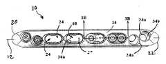
도 1a 및 도 1b는 각각 일종의 릴리프-스페이스를 포함하는 본 발명에 의한 뼈 플레이트의 상면도와, 뼈 플레이트의 제 1 단부의 클로즈업도이다.1A and 1B are a top view of a bone plate according to the invention, each comprising a kind of relief-space, and a close-up view of a first end of the bone plate.
도 2a 및 도 2b는 각각 선택 타입의 릴리프-스페이스(relief space)를 포함하는 본 발명에 의한 뼈 플레이트의 상면도와, 뼈 플레이트의 제 1 단부의 클로즈업도이다.2A and 2B are a top view of a bone plate according to the invention, each comprising a relief type of a selection type, and a close-up view of a first end of the bone plate.
도 3a 및 도 3b는 도 1a 및 도 2a에 도시된 뼈 플레이트의 3-3 선 단면도이고, 릴리프-스페이스의 배치를 나타내는 도면이다.3A and 3B are cross-sectional views taken along line 3-3 of the bone plate shown in FIGS. 1A and 2A, showing the layout of the relief-space.
도 4는 본 발명에 의한 뼈 플레이트와 나사의 조립예의 측면도이다.Figure 4 is a side view of an example of assembly of the bone plate and the screw according to the present invention.
도 5는 뼈에 뼈 플레이트가 고정된 것을 나타낸 개략도이다.5 is a schematic view showing that the bone plate is fixed to the bone.
도 6a 및 도 6b는 (A) 전체 플레이트와 (B) 상세 부분을 나타낸 뼈 플레이트의 대체 실시형태를 나타낸 상부측 사시도이다.6A and 6B are top side perspective views showing alternative embodiments of the bone plate showing (A) the entire plate and (B) the detail.
도 6c 및 도 6d는 각각 뼈 플레이트의 각 부분을 구속한 상태에서의 상면도와 저면도이다.6C and 6D are a top view and a bottom view, respectively, with the respective portions of the bone plate constrained.
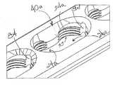
도 6e는 뼈 플레이트에 있어서 뼈 나사가 두개의 컴플렉스-구멍에 삽입된 부분의 상부측 사시도이다.6E is a top side perspective view of the portion of the bone plate where the bone screw is inserted into the two complex-holes.
도 7은 본 발명의 킷의 상면도이다.7 is a top view of the kit of the present invention.
도면을 참조하면 본 발명의 바람직한 실시형태가 사실적이고 개략적으로 도시되어 있다. 도면에서의 동일 구성 요소는 동일 참조 번호로 나타내고, 모든 유사한 구성 요소는 상이한 하위 케이스 문자를 붙인 동일 참조 번호로 나타낸다.Referring to the drawings, preferred embodiments of the present invention are shown realistically and schematically. Like elements in the figures are denoted by the same reference numerals, and all similar components are denoted by the same reference numerals with different lower case letters.
도 1a 및 도 2a에 예시된 바와 같이, 본 발명의 뼈 플레이트(10)는 메인 종축(12), 뼈-접촉 저부측(16)(도 4 참조), 상부측(14) 및 대향 제 1 플레이트 단부(20)와 제 2 플레이트 단부(22)를 구비하고 있다. 플레이트(10)의 상부측(14)으로부터 그 저부측(16)을 통해 연장된 일련의 나사 구멍(24)은 플레이트 축(12)을 따라 형성되어 있다. 나사 구멍(24)은 밑에 있는 뼈에 포인트 뼈 나사(28)가 삽입되는 뼈 나사 가이드로서 기능하여 뼈 플레이트(10)에 의해 보강될 뼈의 다른 부분 또는 조각(80)에 뼈 플레이트(10)를 안착시킨다(도 5 참조). 나사 구멍(24)은 특정 애플리케이션 또는 외과적 프로토콜의 필요에 따라 나사 구멍(24) 부근에서의 뼈 플레이트(10)의 평면에 대하여 수직 또는 각진(angled) 중심(27)(구멍을 통해 삽입될 때 나사가 취하는 통상 경로)을 통하는 나사축(26)을 갖는다.As illustrated in FIGS. 1A and 2A, the
또한, 본 발명의 뼈 플레이트(10)는 "릴리프"-스페이스 피쳐("relief"-space feature)(60)에 의해 인접된 한쌍의 밀집한 나사 구멍(24)을 포함하는 하나 이상의 컴플렉스-구멍(40)을 구비하고 있다. 릴리프-스페이스 피쳐(60)는 두 쌍의 밀집한 나사 구멍(24)의 개구 사이에 배치되고 그 개구와 연결시켜서 "덤-벨(dumb-bell)" 또는 "바-벨"과 같은 구조를 갖는 단일 개구를 가진 컴플렉스-구멍을 제공한다. 릴 리프-스페이스(60)는 스트레이트-슬롯(60a)이나 수축된 또는 "허리모양" 슬롯으로서 구성되는 것이 바람직하다. 릴리프-스페이스는 나사 구멍(24b)의 개구를 연결하는 반경축(42)의 중심에 배치된다. 상기한 바와 같이, 뼈 플레이트(10)는 릴리프-스페이스(60)에 의해 연결된 두개의 나사 시트 구멍(threaded-seat aperture)(34a)으로 이루어진 하나 이상의 컴플렉스 나사 구멍(40)을 구비하고 있다. 그러나, 두개 이상의 나사 구멍(24)으로 이루어진 다중 나사 구멍(40)(도시되지 않음)이 예상되지만 한쌍 이상의 나사 구멍(24)은 릴리프-스페이스(60)에 의해 분리된다. 도 1a 및 도 1b의 바람직한 실시형태에서는 릴리프-스페이스(60)가 수축된 또는 "허리모양" 릴리프(60b)이다. 도 1b를 참조하면, 수축된 또는 허리모양 릴리프(60b)는 밀집한 구멍(24b)의 반경축(42)에 대하여 코드(cord)가 평행한 두개의 대향 아치형 벽에 의해 한쌍의 밀집한 나사 구멍(24b) 사이에서 결정된 릴리프-스페이스(60)이다. 도 2a 및 도 2b에 도시된 다른 바람직한 실시형태의 릴리프-스페이스(60)는 스트레이트-슬롯 릴리프(60a)이다. 스트레이트-슬롯 릴리프는 두개의 대향 평행 벽(60a)에 의해 한쌍의 밀집한 나사 구멍(34a) 사이에서 형성된다.In addition, the
컴플렉스-구멍(40)은 플레이트 축(12)에서 먼 단부와 가까운 단부상에 와이드 베벨(wide bevel)(41)을 구비하여 다면 헤드-시트(multifaceted head-seat)(34)를 형성한다(예컨대, 도 6e 참조). 다면 헤드-시트 피쳐의 예는 긴형상 플레이트(11)의 적어도 상부측(14)상에 나사 표면, 고리 표면, 및 테이퍼진 리드-인 표면(tapered lead-in surface)을 포함한다. 테이퍼진 리드-인 표면은 도면에 도시된 바와 같이 긴형상 챔버가 될 수도 있다.The complex-
또한, 본 발명의 뼈 플레이트(10)는 각진 나사 구멍(angled screw aperture)(24a)을 포함한다. 도 1b 및 도 2b를 참조하면, 두개의 각진 구멍(24a)[뼈 플레이트(10)의 플레이트 단부(20, 22) 중 하나 이상에 가장 근접하여 배치되는 것이 바람직함]은 뼈 플레이트(10)의 저부측(16)의 평면에 대한 수직선으로부터 각을 이루는 나사축(26)을 갖고, 대향하는 배향인 것이 바람직하다. 배향은 당업자에 의해 선택되어 수술 방법의 다양성을 위한 최적의 실용성을 제공할 수 있다. 이 특정 실시형태에서 플레이트 단부(20, 22)에서의 각진 구멍(24a)은 뼈 플레이트(10)의 저부측(16)의 평면에 대하여 거의 45°로 기울어져 있다. 각진 구멍(24a)은 뼈 조각(80)에 뼈 플레이트(10)를 안착시키기 위해 서로에 대하여 대향 각도로 뼈 나사(28)를 수용 및 안내하도록 배치된다(도 5 참조).In addition, the
나사 구멍(24)은 다수의 구조 나사 헤드(30)와 섕크(shank)(32) 구조를 갖는 뼈 나사(28)에 보충되도록 구성될 수 있다는 것을 주목해야 한다. 예컨대, 도 3a 및 도 3b에 예시된 바와 같이, 뼈 나사(28)는 나사 헤드(30a) 또는 비나사 헤드(30b)를 구비할 수 있다. 또한, 나사 헤드(30a)를 갖는 뼈 나사(28)는 나사 섕크(32a) 또는 비나사 섕크(32b)를 구비할 수 있다(도 7 참조). 따라서, 나사 구멍(24)은 나사 시트(34a) 또는 비나사 시트(34b)인 뼈 나사(28)를 수용하는 헤드-시트(34)를 구비하여 나사 헤드(30a) 또는 비나사 헤드(30b)를 구비한 뼈 나사(28)를 각각 수용할 수 있다. 뼈 플레이트(10)는 록킹 뼈 페그(50), 즉 나사 헤드(30a)와 비나사 섕크(32b)을 갖는 뼈 나사(28)를 선택적으로 사용할 수 있다(도 7 참조). 뼈 페그(50)의 헤드내의 스레드 컷(thread cut)은 골절을 더 확실히 고정하기 위해 나사 구멍(34a)에 의해 록킹되도록 설계되는 것이 바람직하다. 사용된 록킹 피쳐는 기계적 수단에 의해 스레드를 록킹하는 모든 공지의 방법이 될 수 있다.It should be noted that the
도 3b 및 도 6c를 참조하면 이중 구멍(40)의 두개의 나사 구멍(24)에 있어서의 중심간 거리(d)는 두개의 나사 구멍(24b)의 반경의 합과 거의 일치, 즉 r1+r2=d이다. 이러한 구조는 긴형상 플레이트(11)를 통해 뼈 나사(28)의 설치를 가능하게 하여 뼈 나사(28)의 헤드(32)가 가능한 한 근접 또는 심지어 접촉되어 배치될 수 있다.3B and 6C, the distance d between the centers of the two
도 4에 도시된 실시형태에서 한쌍의 각진 나사 구멍(24a)이 뼈 나사(28)를 통해 설치된 뼈 플레이트(10)의 제 1 플레이트 단부(20)에서 보여진다. 본 실시형태에서 제 1 플레이트 단부(20)에서 각진 나사 구멍(24a)의 나사축(26)은 제 2 플레이트 단부(22)를 향하여 기울어져 있다. 긴형상 플레이트(11)의 축(12)을 갖는 뼈 나사축(26a, 26b)에 의해 형성된 통상의 삼각 구조는 설치된 뼈 플레이트(10)를 풀리게 할 수 있는 광범위의 힘에 저항할 수 있는 삼각 트러스형 구조(triangular truss-like structure)를 형성한다. 따라서, 이러한 구조는 광범위의 방향으로부터 다가오는 당김력에 저항한다. 도 4는 제 1 플레이트 단부(20)에서의 각진 나사 구멍(24a)의 나사축(26)이 제 2 플레이트 단부(22)를 향하여 기울어지게 도시되어 있지만, 도 1b 및 도 2b에 도시된 바와 같이, 반대 방향으로 기울어질 수 있다. 또한, 플레이트 단부(20, 22)와 가장 근접한 나사 구멍(24)은 뼈 플레이트(10)의 중간부에 위치된 나사 구멍(24)과 독립적이다. 다른 바람직한 실시형태에 있어서, 한쌍의 각진 나사 구멍(24a)은 뼈 플레이트(10)의 제 1 및 제 2 플레이트 단부(20, 22)(도 1a 및 도 2a 참조) 또는 긴형상 플레이트(11)상의 기타 위치에 배치될 수 있다.In the embodiment shown in FIG. 4, a pair of
도 5를 참조하면 다른 실시형태에 있어서, 뼈 플레이트(10)는 슬개골 내측 탈구를 교정하는 대퇴부 골절(44) 및/또는 대퇴골의 교정 가능한 다른 골절술에 특히 적합하다. 뼈 플레이트(10)는 메인 종축(12), 뼈 접촉 저부측(16), 및 상부측(14)으로부터 저부측(16)까지 플레이트(11)를 통해 연통된 한쌍의 근접 나사 구멍(24)을 구비한 하나 이상의 컴플렉스-구멍(40)을 갖는 상부측(14)을 구비하고 있다. 근접 나사 구멍(24)쌍은 다면 나사 헤드 표면(34)을 구비하고 있다. 긴형상 플레이트(11)가 뼈(80)에 부착될 때 두개의 컴플렉스-구멍(40)이 골절 부위(44)의 대향측(51)상에 놓여지도록 배치되는 것이 바람직하다. 도시된 바와 같이, 뼈 플레이트(10)는 두 쌍의 각진 구멍(24a)도 구비하고 있다. 나사 구멍(24)의 쌍은 함께 가압 부속품으로서 기능할 수 있다. 뼈 부분(80)에 부착할 때 나사 구멍(24)의 각 쌍은 골절 부위(44)의 대향면(51)상에 놓여지도록 배치될 수 있다.Referring to FIG. 5, in another embodiment, the
본 발명에 의한 뼈 플레이트(10a)의 대체 실시형태가 도 6a 내지 도 6e에 도시되어 있다. 이 실시형태에서 컴플렉스-구멍(40a)은 상기 컴플렉스-구멍과 유사하지만 하나 또는 두개의 나사 구멍(24)의 나사 헤드-시트(34) 부분에 배치된 릴리프 노치(relief notch)(84)를 구비하고 있는 점에서 다르다. 릴리프 노치(84)는 이것이 없을 때 유사하게 이루어지지 않는 바람직한 장점을 제공한다. 예컨대, 도 6c에 도시된 바와 같이, 셀프-록킹 인서트(92)는 노치(84)에 배치되어 나사 구멍(24a)내에 세팅된 나사 헤드 뼈 나사(30a)를 세팅하기 위해 증가된 마찰을 제공할 수 있 다. 또한, 도 6c에 도시된 바와 같이, 나사 구멍(24)이 하나 이상의 릴리프 노치(84a)를 구비할 수 있다고 생각된다. 본 발명의 노치 피쳐의 장점의 다른 예가 도 6e에 도시되어 있고, 긴형상 플레이트(11)의 저면을 따라 통과하는 제 1 뼈 나사(28d) 주위에 텐셔닝 와이어(tensioning wire)(88)가 루핑(looping)될 수 있고, 인접한 제 2 뼈 나사(28e)내에 리세스 노치(recess notch)(84b)를 통해 긴형상 플레이트(11)의 상부측(14)까지 와이어의 단부가 드러잉 업(drawing up)된 것으로 도시되어 있다. 도 6d에 도시된 실시형태에서 긴형상 플레이트(11)의 저부측(16)에는 플레이트(11)의 저부측의 표면으로 오목하게 된 클리어런스 채널(94, 94a)이 형성되어 있다. 클리어런스 채널은 릴리프 노치(84)와 연통하여 뼈 나사(28)가 뼈 플레이트(10a)에 대하여 세팅된 후 릴리프 노치(84)를 통해 용이하게 제거될 텐셔닝 와이어(88)의 경로를 제공한다.An alternative embodiment of the bone plate 10a according to the present invention is shown in FIGS. 6A-6E. In this embodiment the complex-
노치 피쳐(84)는 하나 이상의 나사 표면 부분(35)과 하나의 비나사 표면 부분(35a)을 갖는 나사 헤드-시트(34a)를 구비한 나사 구멍(24)을 형성한다. 컴플렉스-구멍(40a)에 있어서, 노치 피쳐(84)는 나사 헤드-시트(34a)가 두개 이상의 나사 표면 부분(35)과 두개의 비나사 표면 부분(36)을 구비하고, 두개 이상의 비나사 표면 부분 중 하나는 릴리프 존(60)인 나사 구멍(24)을 형성한다.
도 7을 참조하면 다른 실시형태는 셰이핑(shaping)된 구획 공간(104)에 수용될 키트 아이템(kit item)(106)의 형상에 대응하는 셰이핑된 구획 공간(104)을 바람직하게 구비한 구획된 컨테이너(102)를 포함하는 정형외과 뼈 플레이트 키트(100)를 포함한다. 키트(100)에 포함된 키트 아이템(106)은 동일 또는 유사한 긴 형상 플레이트 피쳐(11a 및 11b)를 구비한 하나 이상의 뼈 플레이트(10)와 복수의 뼈 나사(28)를 포함한다. 뼈 나사(28)는 본 발명의 나사 구멍(24)을 갖고 실행 가능한 각종의 다소 상이한 구조가 될 수 있다는 것을 주목하라. 예로서, 키트(100)내에 포함된 것은 나사 헤드 뼈 나사(30a), 비나사 헤드 뼈 나사(30a)(모두 나사 섕크를 가짐), 및 나사 헤드 페그(32b)(즉, 비나사 섕크)이고, 이 모두는 다양한 길이가 될 수 있다. 키트(100)내에 추가적으로 도시된 것은 드릴 가이드(110)이다. 드릴 가이드(110)는 나사 구멍(24)상의 나사 시트(34a)에 나사 결합될 수 있는 나사 단부(112)를 구비하고 있다. 드릴 가이드는 나사 구멍(24)을 통해 뼈에 삽입될 뼈 나사(28)를 위해 뼈에 파일롯 구멍(pilot hole)을 드릴링하는데 사용하기 위한 드릴 비트(drill bit)(도시되지 않음)용 가이드로서 기능하는 중공 구멍(114)을 구비하고 있다.With reference to FIG. 7, another embodiment is a compartmentalized, preferably provided with shaped
오버래핑된 나사 구멍(즉, 그 중심간 거리는 d보다 작음)의 경우와 다른 장점에 있어서, 외과 의사는 서로 인접한 가장 근접한 위치에서 나란히 두개의 뼈 나사(28)를 배치할 수 있다.In another advantage over the overlapped screw hole (ie the distance between the centers is less than d), the surgeon can place the two
다른 장점에 있어서, 본 발명은 외과 의사가 Synthes S.A.에 의해 설립된 AO 인스티튜트에 의해 조달된 것과 같은 표준 스페이싱을 유지할 수 있도록 매우 근접한 뼈 나사 사이에서 스페이싱을 가능하게 한다.In another advantage, the present invention allows spacing between bone screws in close proximity so that the surgeon can maintain standard spacing as procured by the AO Institute established by Synthes S.A.
다른 장점에 있어서, 나사 구멍(24) 사이에서 골절이 발생하는 경우, 외과 의사는 골절의 반대측상에 두개의 뼈 나사(28)를 배치함으로써 최적의 치료를 위해 파손된 뼈 부분(80)을 더 잘 고정할 수 있다.In another advantage, if a fracture occurs between the screw holes 24, the surgeon may further locate the broken bone portion 80 for optimal treatment by placing two
본 발명의 장점에 있어서, 뼈 플레이트(10)는 확실한 고정을 제공하는 나사 헤드 페그(50)가 말단부를 포함하는 긴형상 플레이트(11)를 따라 소정의 간격을 두고 배치될 수 있다는 점에서 외과 의사에게 선택의 유연성을 제공한다.In the advantage of the present invention, the
다른 장점에 있어서, 뼈 플레이트(10)는 긴형상 플레이트(11)의 종축(12)을 따라 배향되고, 종축(12)에 각을 이루어 배향되어 축(12)을 따라 교대로 된 멀티플 컴플렉스-구멍(40)을 제공함으로써 더 많은 선택의 유연성을 제공한다.In another advantage, the
또 다른 장점에 있어서, 긴형상 플레이트(11)의 나사 헤드 구멍(34a)에 긴형상 플레이트(11)의 상부측(14)에 수직인 나사축(26)뿐만 아니라 긴형상 플레이트(11)의 상부측(14)과 직교하지 않고 각을 이룬 나사축(26)에 대하여 스레드 컷이 제공된다.In a further advantage, the upper part of the
이러한 컴플렉스 뼈 플레이트(10)의 구조는 환자의 생리 기능에 따라 변경될 수 있다. 플레이트(80)의 적용 유연성의 예시는 골절에 유연하게 사용된다.The structure of the
상기한 본 발명의 실시형태에 있어서 다양한 변경 및 수정이 가능하다. 본 발명의 예시적 실시형태를 설명했지만 상기 실시형태에 있어서 광범위한 수정, 변경, 및 치환이 고려된다. 예컨대, 본 발명의 몇가지 피쳐는 다른 피쳐의 대응 사용없이 채택될 수 있다. 따라서, 상기 설명은 설명, 예시 및 청구항에 의해서만 제한되는 본 발명의 사상과 범위로서만 주어진 것으로 넓게 해석 및 이해될 수 있다.Various changes and modifications are possible in the above-described embodiment of the present invention. Although exemplary embodiments of the invention have been described, a wide variety of modifications, changes, and substitutions are contemplated in the above embodiments. For example, some features of the invention may be employed without the corresponding use of other features. Accordingly, the above description may be broadly interpreted and understood to be given only in the spirit and scope of the invention, which is limited only by the description, examples and claims.
Claims (14)
Translated fromKoreanApplications Claiming Priority (5)
| Application Number | Priority Date | Filing Date | Title |
|---|---|---|---|
| US80672806P | 2006-07-07 | 2006-07-07 | |
| US80673006P | 2006-07-07 | 2006-07-07 | |
| US60/806,728 | 2006-07-07 | ||
| US60/806,730 | 2006-07-07 | ||
| PCT/IB2007/001895WO2008007196A2 (en) | 2006-07-07 | 2007-07-06 | Bone plate with complex, adjacent holes joined by a relief-space |
Publications (2)
| Publication Number | Publication Date |
|---|---|
| KR20090040295Atrue KR20090040295A (en) | 2009-04-23 |
| KR101408732B1 KR101408732B1 (en) | 2014-07-02 |
Family
ID=38786943
Family Applications (1)
| Application Number | Title | Priority Date | Filing Date |
|---|---|---|---|
| KR1020097001062AExpired - Fee RelatedKR101408732B1 (en) | 2006-07-07 | 2007-07-06 | Bone plate with adjacent holes connected by the complex and relief-space |
Country Status (11)
| Country | Link |
|---|---|
| US (2) | US8252032B2 (en) |
| EP (1) | EP2037827B1 (en) |
| JP (1) | JP5422858B2 (en) |
| KR (1) | KR101408732B1 (en) |
| CN (1) | CN101505670B (en) |
| AU (1) | AU2007273986B2 (en) |
| BR (1) | BRPI0713865A2 (en) |
| CA (1) | CA2656872C (en) |
| DK (1) | DK2037827T3 (en) |
| ES (1) | ES2524612T3 (en) |
| WO (1) | WO2008007196A2 (en) |
Families Citing this family (109)
| Publication number | Priority date | Publication date | Assignee | Title |
|---|---|---|---|---|
| US7951176B2 (en) | 2003-05-30 | 2011-05-31 | Synthes Usa, Llc | Bone plate |
| US11259851B2 (en) | 2003-08-26 | 2022-03-01 | DePuy Synthes Products, Inc. | Bone plate |
| DE20321551U1 (en) | 2003-08-26 | 2007-12-27 | Synthes Gmbh | bone plate |
| US8574268B2 (en) | 2004-01-26 | 2013-11-05 | DePuy Synthes Product, LLC | Highly-versatile variable-angle bone plate system |
| US7637928B2 (en) | 2004-01-26 | 2009-12-29 | Synthes Usa, Llc | Variable angle locked bone fixation system |
| US11291484B2 (en) | 2004-01-26 | 2022-04-05 | DePuy Synthes Products, Inc. | Highly-versatile variable-angle bone plate system |
| US9055981B2 (en) | 2004-10-25 | 2015-06-16 | Lanx, Inc. | Spinal implants and methods |
| US8241330B2 (en) | 2007-01-11 | 2012-08-14 | Lanx, Inc. | Spinous process implants and associated methods |
| US20070198016A1 (en)* | 2006-02-21 | 2007-08-23 | Osteomed, L.P. | Compression stabilizing spacers |
| US9265532B2 (en) | 2007-01-11 | 2016-02-23 | Lanx, Inc. | Interspinous implants and methods |
| US9247968B2 (en) | 2007-01-11 | 2016-02-02 | Lanx, Inc. | Spinous process implants and associated methods |
| AU2008318657A1 (en)* | 2007-10-30 | 2009-05-07 | Synthes Gmbh | Variable angle locked bone plate |
| US8728126B2 (en)* | 2008-03-10 | 2014-05-20 | Dennis L. Steffen | Bone fixation system and method |
| US20090228010A1 (en)* | 2008-03-10 | 2009-09-10 | Eduardo Gonzalez-Hernandez | Bone fixation system |
| AU2008354730A1 (en) | 2008-04-17 | 2009-10-22 | Toby Orthopaedics, Inc. | Soft tissue attachment system and clip |
| US8257407B2 (en)* | 2008-04-23 | 2012-09-04 | Aryan Henry E | Bone plate system and method |
| WO2009140742A1 (en)* | 2008-05-21 | 2009-11-26 | Adnan Dizdar | Human orthopedic implant plate with double screw holes |
| US10251757B2 (en)* | 2008-09-17 | 2019-04-09 | Skeletal Dynamics Llc | Grooved slot allowing adjustment of the position of a bone fixation device for osteosynthesis |
| EP2248479B1 (en) | 2009-05-06 | 2012-09-19 | Greatbatch Ltd. | Bone plate assembly |
| US8986353B2 (en)* | 2009-07-09 | 2015-03-24 | Orthohelix Surgical Designs, Inc. | Osteotomy plate, plate driver and method for their use |
| US10390867B2 (en) | 2009-09-18 | 2019-08-27 | Biomet C.V. | Bone plate system and method |
| WO2011035103A2 (en)* | 2009-09-18 | 2011-03-24 | Depuy Products, Inc. | Disposable orthopaedic surgery kit and components |
| CN102740786A (en)* | 2009-12-22 | 2012-10-17 | 托比骨科有限公司 | Bone plate and tool assembly and method for use thereof |
| KR101768706B1 (en)* | 2010-03-04 | 2017-08-16 | 신세스 게엠바하 | Ulna osteotomy system |
| US20110218580A1 (en) | 2010-03-08 | 2011-09-08 | Stryker Trauma Sa | Bone fixation system with curved profile threads |
| US9113970B2 (en) | 2010-03-10 | 2015-08-25 | Orthohelix Surgical Designs, Inc. | System for achieving selectable fixation in an orthopedic plate |
| US8961573B2 (en) | 2010-10-05 | 2015-02-24 | Toby Orthopaedics, Inc. | System and method for facilitating repair and reattachment of comminuted bone portions |
| WO2012058448A2 (en) | 2010-10-27 | 2012-05-03 | Toby Orthopaedics, Llc | System and method for fracture replacement of comminuted bone fractures or portions thereof adjacent bone joints |
| BR112013020956B1 (en)* | 2011-02-14 | 2020-12-08 | Synthes Gmbh | bone fixation set |
| WO2012119146A2 (en) | 2011-03-03 | 2012-09-07 | Toby Orthopaedics, Llc | Anterior lesser tuberosity fixed angle fixation device and method of use associated therewith |
| TWI536952B (en)* | 2011-06-27 | 2016-06-11 | 陳瑾惠 | In-situ deformable mini-bone plate and deforming method thereof |
| WO2013036362A1 (en) | 2011-09-06 | 2013-03-14 | Synthes Usa, Llc | Pancarpal arthrodesis bone plate |
| CA2847608C (en) | 2011-09-16 | 2016-07-05 | Stryker Trauma Gmbh | Polyaxial locking hole arrangement |
| US11812923B2 (en) | 2011-10-07 | 2023-11-14 | Alan Villavicencio | Spinal fixation device |
| US9271772B2 (en) | 2011-10-27 | 2016-03-01 | Toby Orthopaedics, Inc. | System and method for fracture replacement of comminuted bone fractures or portions thereof adjacent bone joints |
| US9730797B2 (en) | 2011-10-27 | 2017-08-15 | Toby Orthopaedics, Inc. | Bone joint replacement and repair assembly and method of repairing and replacing a bone joint |
| US9402667B2 (en) | 2011-11-09 | 2016-08-02 | Eduardo Gonzalez-Hernandez | Apparatus and method for use of the apparatus for fracture fixation of the distal humerus |
| US9681902B2 (en) | 2012-02-13 | 2017-06-20 | Stryker European Holdings I, Llc | Attachment device for a bone plate |
| US9387022B2 (en) | 2012-06-27 | 2016-07-12 | DePuy Synthes Products, Inc. | Variable angle bone fixation device |
| US9265542B2 (en)* | 2012-06-27 | 2016-02-23 | DePuy Synthes Products, Inc. | Variable angle bone fixation device |
| US9283008B2 (en) | 2012-12-17 | 2016-03-15 | Toby Orthopaedics, Inc. | Bone plate for plate osteosynthesis and method for use thereof |
| US9545276B2 (en) | 2013-03-15 | 2017-01-17 | Aristotech Industries Gmbh | Fixation device and method of use for a lapidus-type plantar hallux valgus procedure |
| US9333014B2 (en) | 2013-03-15 | 2016-05-10 | Eduardo Gonzalez-Hernandez | Bone fixation and reduction apparatus and method for fixation and reduction of a distal bone fracture and malunion |
| US20160166350A1 (en)* | 2013-08-02 | 2016-06-16 | Flower Orthopedics Corporation | Single-Use, Sterile Orthopedic Implant Kits and Methods of Providing Said Kits |
| US9468479B2 (en) | 2013-09-06 | 2016-10-18 | Cardinal Health 247, Inc. | Bone plate |
| AU2014365821B2 (en) | 2013-12-20 | 2019-10-03 | Crossroads Extremity Systems, Llc | Polyaxial locking hole |
| US9707021B2 (en)* | 2014-06-30 | 2017-07-18 | DePuy Synthes Products, Inc. | Variable angle locking rotation correction plate |
| JP2017529886A (en) | 2014-07-10 | 2017-10-12 | クロスローズ エクストリミティ システムズ リミテッド ライアビリティ カンパニー | Bone implant and means of insertion |
| US11202626B2 (en) | 2014-07-10 | 2021-12-21 | Crossroads Extremity Systems, Llc | Bone implant with means for multi directional force and means of insertion |
| US9814502B2 (en)* | 2014-08-21 | 2017-11-14 | Theodore I Malinin | Bone plate and method of use |
| CA2983488C (en)* | 2015-04-24 | 2020-12-22 | Biomet Manufacturing, Llc | Clavicle implants |
| WO2017011589A1 (en) | 2015-07-13 | 2017-01-19 | Crossroads Extremity Systems, Llc | Bone plates with dynamic elements |
| US10687874B2 (en) | 2015-08-27 | 2020-06-23 | Globus Medical, Inc | Proximal humeral stabilization system |
| US11076898B2 (en) | 2015-08-27 | 2021-08-03 | Globus Medical, Inc. | Proximal humeral stabilization system |
| US11197682B2 (en) | 2015-08-27 | 2021-12-14 | Globus Medical, Inc. | Proximal humeral stabilization system |
| GB2557840B (en)* | 2015-09-18 | 2021-07-21 | Smith & Nephew Inc | Bone plate |
| US10130402B2 (en) | 2015-09-25 | 2018-11-20 | Globus Medical, Inc. | Bone fixation devices having a locking feature |
| US9974581B2 (en) | 2015-11-20 | 2018-05-22 | Globus Medical, Inc. | Expandable intramedullary systems and methods of using the same |
| US10743920B2 (en)* | 2015-12-08 | 2020-08-18 | Arthrex, Inc. | Bone compression plate |
| US20170202586A1 (en)* | 2015-12-11 | 2017-07-20 | DePuy Synthes Products, Inc. | Composite implant trial |
| US9795411B2 (en) | 2016-03-02 | 2017-10-24 | Globus Medical, Inc. | Fixators for bone stabilization and associated systems and methods |
| US10531905B2 (en) | 2016-04-19 | 2020-01-14 | Globus Medical, Inc. | Implantable compression screws |
| US10575884B2 (en) | 2016-08-17 | 2020-03-03 | Globus Medical, Inc. | Fracture plates, systems, and methods |
| US11213327B2 (en) | 2016-08-17 | 2022-01-04 | Globus Medical, Inc. | Fracture plates, systems, and methods |
| US11331128B2 (en) | 2016-08-17 | 2022-05-17 | Globus Medical Inc. | Distal radius stabilization system |
| US10687873B2 (en) | 2016-08-17 | 2020-06-23 | Globus Medical Inc. | Stabilization systems |
| US10751098B2 (en) | 2016-08-17 | 2020-08-25 | Globus Medical Inc. | Stabilization systems |
| US11432857B2 (en) | 2016-08-17 | 2022-09-06 | Globus Medical, Inc. | Stabilization systems |
| US10383668B2 (en) | 2016-08-17 | 2019-08-20 | Globus Medical, Inc. | Volar distal radius stabilization system |
| US11141204B2 (en) | 2016-08-17 | 2021-10-12 | Globus Medical Inc. | Wrist stabilization systems |
| US11197701B2 (en) | 2016-08-17 | 2021-12-14 | Globus Medical, Inc. | Stabilization systems |
| US10420596B2 (en) | 2016-08-17 | 2019-09-24 | Globus Medical, Inc. | Volar distal radius stabilization system |
| US10820930B2 (en) | 2016-09-08 | 2020-11-03 | DePuy Synthes Products, Inc. | Variable angle bone plate |
| US10905476B2 (en) | 2016-09-08 | 2021-02-02 | DePuy Synthes Products, Inc. | Variable angle bone plate |
| US10624686B2 (en) | 2016-09-08 | 2020-04-21 | DePuy Synthes Products, Inc. | Variable angel bone plate |
| US10299847B2 (en) | 2016-09-22 | 2019-05-28 | Globus Medical, Inc. | Systems and methods for intramedullary nail implantation |
| US10610273B2 (en)* | 2016-11-07 | 2020-04-07 | In2Bones Usa, Llc | Bone plate with transverse screw |
| US11864753B2 (en) | 2017-02-06 | 2024-01-09 | Crossroads Extremity Systems, Llc | Implant inserter |
| EP3579762B1 (en) | 2017-02-07 | 2024-06-26 | Crossroads Extremity Systems, LLC | Counter-torque implant |
| US10881438B2 (en) | 2017-03-10 | 2021-01-05 | Globus Medical, Inc. | Clavicle fixation system |
| US10368928B2 (en) | 2017-03-13 | 2019-08-06 | Globus Medical, Inc. | Bone stabilization systems |
| US10905477B2 (en) | 2017-03-13 | 2021-02-02 | Globus Medical, Inc. | Bone stabilization systems |
| WO2018187770A1 (en) | 2017-04-06 | 2018-10-11 | Extremity Medical, Llc | Orthopedic plate with modular peg and compression screw |
| KR102026110B1 (en)* | 2017-05-15 | 2019-09-27 | 김정욱 | Plate with improved hole for fixing bone |
| US12318122B2 (en) | 2017-09-13 | 2025-06-03 | Globus Medical, Inc. | Bone stabilization systems |
| US10856920B2 (en) | 2017-09-13 | 2020-12-08 | Globus Medical Inc. | Bone stabilization systems |
| US11096730B2 (en) | 2017-09-13 | 2021-08-24 | Globus Medical Inc. | Bone stabilization systems |
| US12185986B2 (en) | 2018-01-30 | 2025-01-07 | Orthopediatrics Corp. | Segmental tensioning of spinal tethers |
| US11457964B2 (en) | 2018-02-27 | 2022-10-04 | 41Medical Ag | Variable angle bone plate system |
| US11224468B2 (en) | 2018-03-02 | 2022-01-18 | Globus Medical, Inc. | Distal tibial plating system |
| EP4108194A1 (en) | 2018-03-02 | 2022-12-28 | Stryker European Holdings I, LLC | Bone plates and associated screws |
| US11071570B2 (en) | 2018-03-02 | 2021-07-27 | Globus Medical, Inc. | Distal tibial plating system |
| US11026727B2 (en) | 2018-03-20 | 2021-06-08 | DePuy Synthes Products, Inc. | Bone plate with form-fitting variable-angle locking hole |
| US10772665B2 (en)* | 2018-03-29 | 2020-09-15 | DePuy Synthes Products, Inc. | Locking structures for affixing bone anchors to a bone plate, and related systems and methods |
| US11141172B2 (en) | 2018-04-11 | 2021-10-12 | Globus Medical, Inc. | Method and apparatus for locking a drill guide in a polyaxial hole |
| US11013541B2 (en) | 2018-04-30 | 2021-05-25 | DePuy Synthes Products, Inc. | Threaded locking structures for affixing bone anchors to a bone plate, and related systems and methods |
| EP3808294B1 (en)* | 2018-06-12 | 2024-08-07 | Olympus Terumo Biomaterials Corp. | Bone plate and bone plate kit |
| US10925651B2 (en) | 2018-12-21 | 2021-02-23 | DePuy Synthes Products, Inc. | Implant having locking holes with collection cavity for shavings |
| US11202663B2 (en) | 2019-02-13 | 2021-12-21 | Globus Medical, Inc. | Proximal humeral stabilization systems and methods thereof |
| FR3098387B1 (en)* | 2019-07-08 | 2021-07-02 | Novastep | Osteosynthesis plate with an anchoring hole intended to cooperate with an osteosynthesis screw for compression of two bone fragments |
| US10743922B1 (en) | 2019-09-27 | 2020-08-18 | Trilliant Surgical Llc | Variable angle locking construct for orthopedic applications |
| US12185995B2 (en) | 2019-10-09 | 2025-01-07 | Globus Medical, Inc. | Bone stabilization systems |
| US11129627B2 (en) | 2019-10-30 | 2021-09-28 | Globus Medical, Inc. | Method and apparatus for inserting a bone plate |
| US11723647B2 (en) | 2019-12-17 | 2023-08-15 | Globus Medical, Inc. | Syndesmosis fixation assembly |
| US12059183B2 (en) | 2020-07-31 | 2024-08-13 | Crossroads Extremity Systems, Llc | Bone plates with dynamic elements and screws |
| USD961081S1 (en) | 2020-11-18 | 2022-08-16 | Crossroads Extremity Systems, Llc | Orthopedic implant |
| EP4460249A1 (en) | 2022-01-04 | 2024-11-13 | Extremity Medical, LLC | Orthopedic plate with locking compression slot |
| US12064150B2 (en) | 2022-01-19 | 2024-08-20 | Globus Medical Inc. | System and method for treating bone fractures |
| WO2025184639A1 (en)* | 2024-03-01 | 2025-09-04 | Costa Surgical Inc. | Fracture plating systems and methods |
Family Cites Families (33)
| Publication number | Priority date | Publication date | Assignee | Title |
|---|---|---|---|---|
| US3659595A (en)* | 1969-10-22 | 1972-05-02 | Edward J Haboush | Compensating plates for bone fractures |
| US3716050A (en)* | 1971-02-11 | 1973-02-13 | F Johnston | Olecranon plate |
| US4696290A (en)* | 1983-12-16 | 1987-09-29 | Acromed Corporation | Apparatus for straightening spinal columns |
| US4611581A (en)* | 1983-12-16 | 1986-09-16 | Acromed Corporation | Apparatus for straightening spinal columns |
| US5057111A (en)* | 1987-11-04 | 1991-10-15 | Park Joon B | Non-stress-shielding bone fracture healing device |
| CH673762A5 (en) | 1987-12-02 | 1990-04-12 | Synthes Ag | |
| FR2680673A1 (en)* | 1991-08-26 | 1993-03-05 | Medical Op | Device for stabilisation of a spine, in particular of the human spine, by a posterior route |
| US5209751A (en)* | 1992-02-19 | 1993-05-11 | Danek Medical, Inc. | Spinal fixation system |
| US5261910A (en) | 1992-02-19 | 1993-11-16 | Acromed Corporation | Apparatus for maintaining spinal elements in a desired spatial relationship |
| US5324290A (en)* | 1992-09-24 | 1994-06-28 | Danek Medical, Inc. | Anterior thoracolumbar plate |
| US5364399A (en)* | 1993-02-05 | 1994-11-15 | Danek Medical, Inc. | Anterior cervical plating system |
| US5681311A (en) | 1994-09-15 | 1997-10-28 | Smith & Nephew, Inc. | Osteosynthesis apparatus |
| CA2189744C (en) | 1995-03-27 | 2003-09-16 | Gilbert Talos | Bone plate |
| JP3041050B2 (en) | 1995-06-05 | 2000-05-15 | ポハング アイアン アンド スチール カンパニー リミテッド | Duplex stainless steel and its manufacturing method |
| ZA983955B (en)* | 1997-05-15 | 2001-08-13 | Sdgi Holdings Inc | Anterior cervical plating system. |
| DK1158915T3 (en)* | 1999-03-09 | 2004-11-08 | Synthes Ag | bone plate |
| CN1172634C (en)* | 1999-09-13 | 2004-10-27 | 库尔斯恩蒂斯股份公司 | Bone plating system |
| EP1255498B1 (en)* | 2000-01-27 | 2005-11-23 | SYNTHES AG Chur | Bone plate |
| US6866665B2 (en) | 2003-03-27 | 2005-03-15 | Hand Innovations, Llc | Bone fracture fixation system with subchondral and articular surface support |
| US20050049594A1 (en)* | 2001-04-20 | 2005-03-03 | Wack Michael A. | Dual locking plate and associated method |
| US6406478B1 (en)* | 2001-05-24 | 2002-06-18 | Robert W. H. Kuo | Bone reinforcement plate for use on the spine |
| US7316687B2 (en)* | 2001-08-24 | 2008-01-08 | Zimmer Technology, Inc. | Blade plate and instruments |
| US20050096657A1 (en)* | 2002-02-26 | 2005-05-05 | Alex Autericque | Osteosynthesis or arthrodesis material comprising a bony plate |
| US7220263B2 (en)* | 2002-10-04 | 2007-05-22 | Seaspine, Inc. | Cervical plate/screw system for immobilizing vertebral bodies |
| BRPI0408769A (en)* | 2003-03-26 | 2006-03-28 | Swiss Orthopedic Solutions Sa | lock bone plate |
| US7722653B2 (en)* | 2003-03-26 | 2010-05-25 | Greatbatch Medical S.A. | Locking bone plate |
| DE10326643A1 (en)* | 2003-06-11 | 2004-12-30 | Mückter, Helmut, Dr. med. Dipl.-Ing. | Osteosynthesis plate or comparable implant with ball sleeve |
| WO2004112587A2 (en)* | 2003-06-20 | 2004-12-29 | Acumed Llc | Bone plates with intraoperatively tapped apertures |
| US7309340B2 (en)* | 2003-06-20 | 2007-12-18 | Medicinelodge, Inc. | Method and apparatus for bone plating |
| US7731721B2 (en)* | 2003-07-16 | 2010-06-08 | Synthes Usa, Llc | Plating system with multiple function drill guide |
| US20050216027A1 (en)* | 2004-03-24 | 2005-09-29 | Suh Sean S | Extraction screwdriver |
| US7137987B2 (en) | 2004-07-02 | 2006-11-21 | Wright Medical Technology, Inc. | Distal radius bone plating system with locking and non-locking screws |
| FR2886535B1 (en)* | 2005-06-06 | 2008-04-25 | Surfix Technologies Sa | DEVICE FOR ARRESSING A SUPPORT, ASSEMBLY PART FOR SUCH A DEVICE AND METHOD OF ARRANGING A DEVICE TO A SUPPORT |
- 2007
- 2007-07-06CNCN200780030653.2Apatent/CN101505670B/ennot_activeExpired - Fee Related
- 2007-07-06ESES07804575.4Tpatent/ES2524612T3/enactiveActive
- 2007-07-06BRBRPI0713865-2Apatent/BRPI0713865A2/ennot_activeApplication Discontinuation
- 2007-07-06USUS12/307,451patent/US8252032B2/ennot_activeExpired - Fee Related
- 2007-07-06KRKR1020097001062Apatent/KR101408732B1/ennot_activeExpired - Fee Related
- 2007-07-06JPJP2009517476Apatent/JP5422858B2/ennot_activeExpired - Fee Related
- 2007-07-06EPEP07804575.4Apatent/EP2037827B1/ennot_activeNot-in-force
- 2007-07-06AUAU2007273986Apatent/AU2007273986B2/ennot_activeCeased
- 2007-07-06CACA2656872Apatent/CA2656872C/ennot_activeExpired - Fee Related
- 2007-07-06WOPCT/IB2007/001895patent/WO2008007196A2/enactiveApplication Filing
- 2007-07-06DKDK07804575.4Tpatent/DK2037827T3/enactive
- 2009
- 2009-03-06USUS12/399,170patent/US8100953B2/ennot_activeExpired - Fee Related
Also Published As
| Publication number | Publication date |
|---|---|
| US8100953B2 (en) | 2012-01-24 |
| DK2037827T3 (en) | 2015-01-05 |
| WO2008007196A2 (en) | 2008-01-17 |
| CN101505670A (en) | 2009-08-12 |
| AU2007273986A1 (en) | 2008-01-17 |
| US20090171399A1 (en) | 2009-07-02 |
| JP2009542279A (en) | 2009-12-03 |
| CA2656872A1 (en) | 2008-01-17 |
| WO2008007196A3 (en) | 2008-03-20 |
| ES2524612T3 (en) | 2014-12-10 |
| JP5422858B2 (en) | 2014-02-19 |
| US20090292318A1 (en) | 2009-11-26 |
| EP2037827A2 (en) | 2009-03-25 |
| CA2656872C (en) | 2014-04-29 |
| AU2007273986B2 (en) | 2013-01-31 |
| US8252032B2 (en) | 2012-08-28 |
| BRPI0713865A2 (en) | 2012-12-11 |
| CN101505670B (en) | 2015-05-20 |
| KR101408732B1 (en) | 2014-07-02 |
| EP2037827B1 (en) | 2014-09-17 |
Similar Documents
| Publication | Publication Date | Title |
|---|---|---|
| KR20090040295A (en) | Bone plate with adjacent holes connected by complex and relief-space | |
| US8512385B2 (en) | Bone plate with complex, adjacent holes joined by a bend relief zone | |
| EP1610700B1 (en) | Locking bone plate | |
| EP1468655B1 (en) | Locking bone plate | |
| US7905883B2 (en) | Locking triple pelvic osteotomy plate and method of use | |
| US20080045960A1 (en) | Locking tpo plate and method of use | |
| US11123118B2 (en) | Periprosthetic bone plates | |
| JP5805624B2 (en) | Multiple screw | |
| EP1861032B1 (en) | Modular fracture fixation plate system | |
| US20200275959A1 (en) | Intra-osseous plate system and method | |
| KR20100101087A (en) | Periprosthetic fracture repair | |
| JP2009056288A (en) | Fixation kit for medical or surgical use |
Legal Events
| Date | Code | Title | Description |
|---|---|---|---|
| PA0105 | International application | St.27 status event code:A-0-1-A10-A15-nap-PA0105 | |
| E13-X000 | Pre-grant limitation requested | St.27 status event code:A-2-3-E10-E13-lim-X000 | |
| P11-X000 | Amendment of application requested | St.27 status event code:A-2-2-P10-P11-nap-X000 | |
| P13-X000 | Application amended | St.27 status event code:A-2-2-P10-P13-nap-X000 | |
| PG1501 | Laying open of application | St.27 status event code:A-1-1-Q10-Q12-nap-PG1501 | |
| R18-X000 | Changes to party contact information recorded | St.27 status event code:A-3-3-R10-R18-oth-X000 | |
| A201 | Request for examination | ||
| PA0201 | Request for examination | St.27 status event code:A-1-2-D10-D11-exm-PA0201 | |
| E902 | Notification of reason for refusal | ||
| PE0902 | Notice of grounds for rejection | St.27 status event code:A-1-2-D10-D21-exm-PE0902 | |
| N231 | Notification of change of applicant | ||
| PN2301 | Change of applicant | St.27 status event code:A-3-3-R10-R13-asn-PN2301 St.27 status event code:A-3-3-R10-R11-asn-PN2301 | |
| P11-X000 | Amendment of application requested | St.27 status event code:A-2-2-P10-P11-nap-X000 | |
| P13-X000 | Application amended | St.27 status event code:A-2-2-P10-P13-nap-X000 | |
| E701 | Decision to grant or registration of patent right | ||
| PE0701 | Decision of registration | St.27 status event code:A-1-2-D10-D22-exm-PE0701 | |
| GRNT | Written decision to grant | ||
| PR0701 | Registration of establishment | St.27 status event code:A-2-4-F10-F11-exm-PR0701 | |
| PR1002 | Payment of registration fee | St.27 status event code:A-2-2-U10-U12-oth-PR1002 Fee payment year number:1 | |
| PG1601 | Publication of registration | St.27 status event code:A-4-4-Q10-Q13-nap-PG1601 | |
| FPAY | Annual fee payment | Payment date:20170609 Year of fee payment:4 | |
| PR1001 | Payment of annual fee | St.27 status event code:A-4-4-U10-U11-oth-PR1001 Fee payment year number:4 | |
| FPAY | Annual fee payment | Payment date:20180612 Year of fee payment:5 | |
| PR1001 | Payment of annual fee | St.27 status event code:A-4-4-U10-U11-oth-PR1001 Fee payment year number:5 | |
| FPAY | Annual fee payment | Payment date:20190612 Year of fee payment:6 | |
| PR1001 | Payment of annual fee | St.27 status event code:A-4-4-U10-U11-oth-PR1001 Fee payment year number:6 | |
| PR1001 | Payment of annual fee | St.27 status event code:A-4-4-U10-U11-oth-PR1001 Fee payment year number:7 | |
| PC1903 | Unpaid annual fee | St.27 status event code:A-4-4-U10-U13-oth-PC1903 Not in force date:20210612 Payment event data comment text:Termination Category : DEFAULT_OF_REGISTRATION_FEE | |
| PC1903 | Unpaid annual fee | St.27 status event code:N-4-6-H10-H13-oth-PC1903 Ip right cessation event data comment text:Termination Category : DEFAULT_OF_REGISTRATION_FEE Not in force date:20210612 |