KR20090028632A - Self-Adjusting Upper Band with Pressure Data Processing - Google Patents
Self-Adjusting Upper Band with Pressure Data ProcessingDownload PDFInfo
- Publication number
- KR20090028632A KR20090028632AKR1020097001354AKR20097001354AKR20090028632AKR 20090028632 AKR20090028632 AKR 20090028632AKR 1020097001354 AKR1020097001354 AKR 1020097001354AKR 20097001354 AKR20097001354 AKR 20097001354AKR 20090028632 AKR20090028632 AKR 20090028632A
- Authority
- KR
- South Korea
- Prior art keywords
- pressure
- band
- fluid
- volume
- controller
- Prior art date
- Legal status (The legal status is an assumption and is not a legal conclusion. Google has not performed a legal analysis and makes no representation as to the accuracy of the status listed.)
- Withdrawn
Links
- 238000012545processingMethods0.000titleclaimsdescription14
- 239000012530fluidSubstances0.000claimsabstractdescription193
- 239000006185dispersionSubstances0.000claimsabstractdescription56
- 230000002496gastric effectEffects0.000claimsdescription52
- 210000002784stomachAnatomy0.000claimsdescription41
- 238000000034methodMethods0.000claimsdescription40
- 238000004891communicationMethods0.000claimsdescription37
- 230000033228biological regulationEffects0.000claimsdescription36
- 230000008569processEffects0.000claimsdescription18
- 238000012806monitoring deviceMethods0.000claimsdescription9
- 208000008589ObesityDiseases0.000claimsdescription8
- 235000020824obesityNutrition0.000claimsdescription7
- 230000001276controlling effectEffects0.000claimsdescription5
- 210000003238esophagusAnatomy0.000claimsdescription5
- 238000007405data analysisMethods0.000claimsdescription2
- 230000001105regulatory effectEffects0.000claims2
- 238000002513implantationMethods0.000abstractdescription8
- 230000036186satietyEffects0.000abstractdescription4
- 235000019627satietyNutrition0.000abstractdescription4
- 238000012544monitoring processMethods0.000description25
- 230000008859changeEffects0.000description24
- 230000006870functionEffects0.000description21
- 238000004458analytical methodMethods0.000description15
- 230000003750conditioning effectEffects0.000description14
- 239000007943implantSubstances0.000description14
- 238000010586diagramMethods0.000description12
- 230000004044responseEffects0.000description10
- 230000007246mechanismEffects0.000description9
- FAPWRFPIFSIZLT-UHFFFAOYSA-MSodium chlorideChemical compound[Na+].[Cl-]FAPWRFPIFSIZLT-UHFFFAOYSA-M0.000description8
- 238000013461designMethods0.000description8
- 239000000463materialSubstances0.000description8
- 238000004513sizingMethods0.000description8
- 238000005086pumpingMethods0.000description6
- 239000011780sodium chlorideSubstances0.000description6
- 238000003860storageMethods0.000description6
- 238000002474experimental methodMethods0.000description5
- 230000033001locomotionEffects0.000description5
- XLYOFNOQVPJJNP-UHFFFAOYSA-NwaterSubstancesOXLYOFNOQVPJJNP-UHFFFAOYSA-N0.000description5
- 239000012267brineSubstances0.000description4
- 230000000875corresponding effectEffects0.000description4
- 238000012986modificationMethods0.000description4
- 230000004048modificationEffects0.000description4
- 208000001022morbid obesityDiseases0.000description4
- 230000006855networkingEffects0.000description4
- HPALAKNZSZLMCH-UHFFFAOYSA-Msodium;chloride;hydrateChemical compoundO.[Na+].[Cl-]HPALAKNZSZLMCH-UHFFFAOYSA-M0.000description4
- XQFRJNBWHJMXHO-RRKCRQDMSA-NIDURChemical compoundC1[C@H](O)[C@@H](CO)O[C@H]1N1C(=O)NC(=O)C(I)=C1XQFRJNBWHJMXHO-RRKCRQDMSA-N0.000description2
- RTAQQCXQSZGOHL-UHFFFAOYSA-NTitaniumChemical compound[Ti]RTAQQCXQSZGOHL-UHFFFAOYSA-N0.000description2
- 230000009471actionEffects0.000description2
- 238000012790confirmationMethods0.000description2
- 230000003247decreasing effectEffects0.000description2
- 238000009826distributionMethods0.000description2
- 238000005516engineering processMethods0.000description2
- 230000037406food intakeEffects0.000description2
- 235000012631food intakeNutrition0.000description2
- 229960004716idoxuridineDrugs0.000description2
- 238000000338in vitroMethods0.000description2
- 238000012423maintenanceMethods0.000description2
- 238000005259measurementMethods0.000description2
- 230000000737periodic effectEffects0.000description2
- 230000002441reversible effectEffects0.000description2
- 229910052719titaniumInorganic materials0.000description2
- 239000010936titaniumSubstances0.000description2
- 238000012546transferMethods0.000description2
- 208000017667Chronic DiseaseDiseases0.000description1
- 101100366940Mus musculus Stom geneProteins0.000description1
- 239000004696Poly ether ether ketoneSubstances0.000description1
- 210000001015abdomenAnatomy0.000description1
- 210000000683abdominal cavityAnatomy0.000description1
- 239000002253acidSubstances0.000description1
- 230000004913activationEffects0.000description1
- 239000000853adhesiveSubstances0.000description1
- 230000001070adhesive effectEffects0.000description1
- 230000004075alterationEffects0.000description1
- 230000000712assemblyEffects0.000description1
- 238000000429assemblyMethods0.000description1
- 230000008901benefitEffects0.000description1
- JUPQTSLXMOCDHR-UHFFFAOYSA-Nbenzene-1,4-diol;bis(4-fluorophenyl)methanoneChemical compoundOC1=CC=C(O)C=C1.C1=CC(F)=CC=C1C(=O)C1=CC=C(F)C=C1JUPQTSLXMOCDHR-UHFFFAOYSA-N0.000description1
- 239000000560biocompatible materialSubstances0.000description1
- 230000000740bleeding effectEffects0.000description1
- 239000003990capacitorSubstances0.000description1
- 208000012696congenital leptin deficiencyDiseases0.000description1
- 229920001577copolymerPolymers0.000description1
- 230000002596correlated effectEffects0.000description1
- 238000013479data entryMethods0.000description1
- 238000013500data storageMethods0.000description1
- 230000037213dietEffects0.000description1
- 235000005911dietNutrition0.000description1
- 238000007599dischargingMethods0.000description1
- 230000000694effectsEffects0.000description1
- 239000000446fuelSubstances0.000description1
- 239000007789gasSubstances0.000description1
- 238000011902gastrointestinal surgeryMethods0.000description1
- 239000000499gelSubstances0.000description1
- 230000036541healthEffects0.000description1
- 230000005802health problemEffects0.000description1
- 230000006872improvementEffects0.000description1
- 230000006698inductionEffects0.000description1
- 208000015181infectious diseaseDiseases0.000description1
- 238000001802infusionMethods0.000description1
- 239000007788liquidSubstances0.000description1
- 230000007774longtermEffects0.000description1
- 238000004519manufacturing processMethods0.000description1
- 238000003032molecular dockingMethods0.000description1
- 230000008855peristalsisEffects0.000description1
- 229920002530polyetherether ketonePolymers0.000description1
- 238000003825pressingMethods0.000description1
- 230000002035prolonged effectEffects0.000description1
- 230000009467reductionEffects0.000description1
- 238000012552reviewMethods0.000description1
- 238000007789sealingMethods0.000description1
- 230000035945sensitivityEffects0.000description1
- 238000000926separation methodMethods0.000description1
- 229920002379silicone rubberPolymers0.000description1
- 239000007787solidSubstances0.000description1
- 210000001562sternumAnatomy0.000description1
- 238000001356surgical procedureMethods0.000description1
- 238000012360testing methodMethods0.000description1
- 230000001225therapeutic effectEffects0.000description1
- 210000001519tissueAnatomy0.000description1
- 230000000007visual effectEffects0.000description1
- 230000003442weekly effectEffects0.000description1
Images


Classifications
- A—HUMAN NECESSITIES
- A61—MEDICAL OR VETERINARY SCIENCE; HYGIENE
- A61F—FILTERS IMPLANTABLE INTO BLOOD VESSELS; PROSTHESES; DEVICES PROVIDING PATENCY TO, OR PREVENTING COLLAPSING OF, TUBULAR STRUCTURES OF THE BODY, e.g. STENTS; ORTHOPAEDIC, NURSING OR CONTRACEPTIVE DEVICES; FOMENTATION; TREATMENT OR PROTECTION OF EYES OR EARS; BANDAGES, DRESSINGS OR ABSORBENT PADS; FIRST-AID KITS
- A61F2/00—Filters implantable into blood vessels; Prostheses, i.e. artificial substitutes or replacements for parts of the body; Appliances for connecting them with the body; Devices providing patency to, or preventing collapsing of, tubular structures of the body, e.g. stents
- A—HUMAN NECESSITIES
- A61—MEDICAL OR VETERINARY SCIENCE; HYGIENE
- A61B—DIAGNOSIS; SURGERY; IDENTIFICATION
- A61B5/00—Measuring for diagnostic purposes; Identification of persons
- A61B5/03—Measuring fluid pressure within the body other than blood pressure, e.g. cerebral pressure ; Measuring pressure in body tissues or organs
- A61B5/036—Measuring fluid pressure within the body other than blood pressure, e.g. cerebral pressure ; Measuring pressure in body tissues or organs by means introduced into body tracts
- A—HUMAN NECESSITIES
- A61—MEDICAL OR VETERINARY SCIENCE; HYGIENE
- A61B—DIAGNOSIS; SURGERY; IDENTIFICATION
- A61B17/00—Surgical instruments, devices or methods
- A61B17/12—Surgical instruments, devices or methods for ligaturing or otherwise compressing tubular parts of the body, e.g. blood vessels or umbilical cord
- A—HUMAN NECESSITIES
- A61—MEDICAL OR VETERINARY SCIENCE; HYGIENE
- A61B—DIAGNOSIS; SURGERY; IDENTIFICATION
- A61B5/00—Measuring for diagnostic purposes; Identification of persons
- A61B5/0002—Remote monitoring of patients using telemetry, e.g. transmission of vital signals via a communication network
- A61B5/0031—Implanted circuitry
- A—HUMAN NECESSITIES
- A61—MEDICAL OR VETERINARY SCIENCE; HYGIENE
- A61B—DIAGNOSIS; SURGERY; IDENTIFICATION
- A61B5/00—Measuring for diagnostic purposes; Identification of persons
- A61B5/41—Detecting, measuring or recording for evaluating the immune or lymphatic systems
- A61B5/411—Detecting or monitoring allergy or intolerance reactions to an allergenic agent or substance
- A—HUMAN NECESSITIES
- A61—MEDICAL OR VETERINARY SCIENCE; HYGIENE
- A61F—FILTERS IMPLANTABLE INTO BLOOD VESSELS; PROSTHESES; DEVICES PROVIDING PATENCY TO, OR PREVENTING COLLAPSING OF, TUBULAR STRUCTURES OF THE BODY, e.g. STENTS; ORTHOPAEDIC, NURSING OR CONTRACEPTIVE DEVICES; FOMENTATION; TREATMENT OR PROTECTION OF EYES OR EARS; BANDAGES, DRESSINGS OR ABSORBENT PADS; FIRST-AID KITS
- A61F5/00—Orthopaedic methods or devices for non-surgical treatment of bones or joints; Nursing devices ; Anti-rape devices
- A61F5/0003—Apparatus for the treatment of obesity; Anti-eating devices
- A61F5/0013—Implantable devices or invasive measures
- A61F5/005—Gastric bands
- A61F5/0053—Gastric bands remotely adjustable
- A—HUMAN NECESSITIES
- A61—MEDICAL OR VETERINARY SCIENCE; HYGIENE
- A61F—FILTERS IMPLANTABLE INTO BLOOD VESSELS; PROSTHESES; DEVICES PROVIDING PATENCY TO, OR PREVENTING COLLAPSING OF, TUBULAR STRUCTURES OF THE BODY, e.g. STENTS; ORTHOPAEDIC, NURSING OR CONTRACEPTIVE DEVICES; FOMENTATION; TREATMENT OR PROTECTION OF EYES OR EARS; BANDAGES, DRESSINGS OR ABSORBENT PADS; FIRST-AID KITS
- A61F5/00—Orthopaedic methods or devices for non-surgical treatment of bones or joints; Nursing devices ; Anti-rape devices
- A61F5/0003—Apparatus for the treatment of obesity; Anti-eating devices
- A61F5/0013—Implantable devices or invasive measures
- A61F5/005—Gastric bands
- A61F5/0066—Closing devices for gastric bands
- A—HUMAN NECESSITIES
- A61—MEDICAL OR VETERINARY SCIENCE; HYGIENE
- A61B—DIAGNOSIS; SURGERY; IDENTIFICATION
- A61B17/00—Surgical instruments, devices or methods
- A61B17/12—Surgical instruments, devices or methods for ligaturing or otherwise compressing tubular parts of the body, e.g. blood vessels or umbilical cord
- A61B17/132—Tourniquets
- A61B17/135—Tourniquets inflatable
- A61B17/1355—Automated control means therefor
- A—HUMAN NECESSITIES
- A61—MEDICAL OR VETERINARY SCIENCE; HYGIENE
- A61B—DIAGNOSIS; SURGERY; IDENTIFICATION
- A61B2562/00—Details of sensors; Constructional details of sensor housings or probes; Accessories for sensors
- A61B2562/02—Details of sensors specially adapted for in-vivo measurements
- A61B2562/0247—Pressure sensors
- A—HUMAN NECESSITIES
- A61—MEDICAL OR VETERINARY SCIENCE; HYGIENE
- A61B—DIAGNOSIS; SURGERY; IDENTIFICATION
- A61B2562/00—Details of sensors; Constructional details of sensor housings or probes; Accessories for sensors
- A61B2562/04—Arrangements of multiple sensors of the same type
- A61B2562/043—Arrangements of multiple sensors of the same type in a linear array
Landscapes
- Health & Medical Sciences (AREA)
- Life Sciences & Earth Sciences (AREA)
- Engineering & Computer Science (AREA)
- Veterinary Medicine (AREA)
- Biomedical Technology (AREA)
- Heart & Thoracic Surgery (AREA)
- Animal Behavior & Ethology (AREA)
- General Health & Medical Sciences (AREA)
- Public Health (AREA)
- Vascular Medicine (AREA)
- Surgery (AREA)
- Medical Informatics (AREA)
- Molecular Biology (AREA)
- Physics & Mathematics (AREA)
- Biophysics (AREA)
- Pathology (AREA)
- Orthopedic Medicine & Surgery (AREA)
- Obesity (AREA)
- Child & Adolescent Psychology (AREA)
- Nursing (AREA)
- Computer Networks & Wireless Communication (AREA)
- Immunology (AREA)
- Hematology (AREA)
- Reproductive Health (AREA)
- Nuclear Medicine, Radiotherapy & Molecular Imaging (AREA)
- Cardiology (AREA)
- Oral & Maxillofacial Surgery (AREA)
- Transplantation (AREA)
- Surgical Instruments (AREA)
- Measuring Pulse, Heart Rate, Blood Pressure Or Blood Flow (AREA)
- Medicines Containing Plant Substances (AREA)
- Orthopedics, Nursing, And Contraception (AREA)
Abstract
Translated fromKoreanDescription
Translated fromKorean관련 출원에 대한 교차-참조Cross-Reference to the Related Application
본 출원은 2006년 1월 4일 출원된 국제출원 제PCT/US2006/000013호의 일부계속출원이며, 이는 본 명세서에 전체적으로 참조로 포함되어 있다.This application is part of an ongoing application of International Application No. PCT / US2006 / 000013, filed Jan. 4, 2006, which is incorporated herein by reference in its entirety.
1. 발명의 분야1. Field of Invention
본 발명은, 일반적으로 비만을 컨트롤하기 위한 장치 및 방법, 및 더욱 구체적으로, 환자에서 계속적인 스토마(stoma) 크기 조절을 제공하기 위하여 자가-모니터링 및 위 밴드의 크기, 즉, 내부 직경 조절용으로 구성된 위 밴드 또는 위 밴드 어셈블리/시스템 및 상응하는 방법에 관한 것이다.The present invention generally relates to devices and methods for controlling obesity, and more specifically to self-monitoring and size of gastric bands, ie, internal diameter adjustment, to provide continuous stoma sizing in patients. To a configured upper band or upper band assembly / system and a corresponding method.
2. 관련 배경2. Related Background
중증 비만은 더욱더 만연하고 있는 만성 질환으로 의사는 식이요법과 운동만으로는 환자를 치료하기 어렵다. 의사는 전통적인 방법으로 체중감량이 불가능한 중증 비만 환자 또는 심한 비만관련 건강문제를 겪고 있는 환자를 처치하기 위하여 위장 수술을 사용한다.일반적으로, 위장 수술은 음식물 섭취를 제한하여 체중감량 을 촉진하며, 더욱 구체적으로, 제한기능은 위의 상부로부터 더 큰 하부로 좁은 통로 또는 "스토마"를 생성하여 음식물 섭취를 한정하여, 음식물의 양을 감소시키며, 위를 통과하는 음식물의 통로를 고정하여 속도를 느리게 할 수 있다. 초기에, 스토마는 고정된 크기였으나, 더욱 최근에는 의사들이 스토마를 크기를 변경시켜 조절할 수 있다면 더욱 효과적일 것이라고 판단하였다.Severe obesity is a more prevalent chronic disease, which makes it difficult for doctors to treat patients with diet and exercise alone. Doctors use gastrointestinal surgery to treat patients with severe obesity or those with severe obesity-related health problems that are not conventionally able to lose weight. Specifically, the restricting function creates a narrow passage or "stom" from the top of the stomach to a larger bottom to limit food intake, reduce the amount of food, and slow down the speed of the food passage through the stomach. can do. Initially, the story was of a fixed size, but more recently doctors thought it would be more effective if the story could be resized and adjusted.
비만을 위한 이러한 단순한 제한기능에 더욱 일반적으로 사용되는 한가지는 조절가능한 위 밴딩(AGB)이다. 예시적인 AGB 방법에서는, 실리콘 엘라스토머로 제조된 속이 빈 밴드(즉, 위 밴드)를 위의 상단 근처 주위에 배치하고, 작은 파우치 및 위의 나머지 부분으로의 좁은 통로(즉, 스토마)를 생성한다. 그리고 나서, 중공 니들 및 시린지를 사용하여 피부 아래에 위치하는 작은 포트에 엑세스하여 염수 용액으로 밴드를 팽창시킨다. 스토마의 크기를 컨트롤하기 위하여, 시간이 지남에 따라 엑세스 포트를 통해 밴드 내의 염수 용액의 양을 증가시키거나 감소시켜 의사 또는 다른 전문가에 의해 체외에서 위 밴드를 조이거나 풀러서 통로 및 스토마의 크기를 변화시킬 수 있다.One more commonly used for this simple restriction for obesity is adjustable gastric banding (AGB). In an exemplary AGB method, a hollow band (i.e., the upper band) made of silicone elastomer is placed around the upper top, creating a small pouch and a narrow passage (i.e., a storm) to the rest of the upper. . The hollow needle and syringe are then used to access a small port located under the skin to expand the band with saline solution. In order to control the size of the stoma, over time, the amount of saline solution in the band can be increased or decreased through the access port to tighten or loosen the gastric band in vitro by a physician or other specialist to You can change the size.
초기 스토마 크기설정 후에 위 밴드의 미세한 조절을 제공함으로써 조절가능한 위 밴딩 방법이 상당히 향상된다는 것이 입증되었다. 그러나,언제 위 밴드를 추가로 조절해야하는 지, 얼마나 밴드 크기 또는 직경을 증가 또는 감소시켜야 원하는 스토마 크기를 달성할 수 있는지 결정하는 데는 어려움이 계속되고 있다. 의사 또는 다른 전문가가 이식된 위 밴드를 조절할 수 있는 많은 위 밴드가 개발되었다. 일반적을, 이러한 밴드 시스템은 환자와 관련된 파라미터를 측정 또는 결정하기 위 한 센서를 포함하며, 그에 응하여 의사 또는 전문가는 환자 파라미터에 기초하여 밴드 내의 유체의 부피를 조절한다. 예를 들어, 조절가능한 위 밴드 시스템 중 하나는 환자의 스토마 내의 압력이 미리설정된 제한을 초과하는 때를 결정하고 외부 컨트롤 장치에 알람을 제공한다. 그러면, 의사 또는 기타 조작자는 밴드로부터 외부 엑세스 포트 및 충진 라인을 통해 일정량의 유체를 빼서 위 밴드를 풀어 이에 응한다. 다른 위 밴드 시스템에서는, 위 밴드 크기 조절용 구성요소을 환자 체내에 이식하고, 환자의 위압력 또는 신체적 상태와 같은 환자와 관련된 신체 파라미터를 결정할 때, 환자 체외의 외부 컨트롤 유닛이 작동하여 이식된 구성요소을 켜서, 예를 들어, 밴드로부터 미리설정된 부피의 유체를 추가하거나 빼서 밴드의 크기를 조절한다.Providing fine control of the gastric band after initial stroma sizing has demonstrated a significant improvement in the adjustable gastric banding method. However, difficulties continue to determine when to further adjust the band and how to increase or decrease the band size or diameter to achieve the desired story size. Many stomach bands have been developed that allow doctors or other experts to control the implanted stomach bands. In general, such band systems include sensors for measuring or determining parameters associated with a patient, in response the physician or expert adjusts the volume of fluid in the band based on the patient parameters. For example, one of the adjustable stomach band systems determines when the pressure in the patient's story exceeds a preset limit and provides an alarm to the external control device. The surgeon or other operator then disengages the upper band and responds by removing a certain amount of fluid from the band through the external access port and the fill line. In other gastric band systems, an external control unit outside the patient operates to turn on the implanted component when implanting components for gastric band sizing into the patient's body and determining body parameters associated with the patient such as the patient's gastric pressure or physical condition. The size of the band is adjusted, for example, by adding or subtracting a predetermined volume of fluid from the band.
조절가능한 위 밴드에 대해 향상된 컨트롤을 제공하고 있지만, 현존하는 위 밴드는 환자의 요구를 충족시키지 못하고 있다. 일부에서, 현존하는 조절가능한 위밴드의 결점은 환자가 의사 또는 기타 전문가에 의해 처치되는 환자가 위 밴드의 크기 및 형성된 스토마를 외부 컨트롤 유닛을 통해 조절하고자하는 요구로 인한 것이다. 다른 결점은 환자와 관련된 파라미터를 감지하고 이와 원하는 스토마 크기를 상호관련짓는 데 대한 신뢰할 수 없음 및 부정확성과 관련된 것이다. 더욱이, 일부 현존하는 위 밴드는 환자 내에, 예를 들어, 위 내에 또는 상에 센서를 삽입하여 위 압력을 결정할 필요가 있다. 현재 기술의 이러한 및 다른 제한으로 인하여, 비만으로 처치되는 환자에서 스토마 크기의 개선된 조절을 제공하기 위한, 개선된 위 밴딩 시스템, 및 관련 조절 방법이 여전히 요구되고 있다.While providing improved control over the adjustable stomach band, existing stomach bands do not meet the needs of patients. In some cases, a drawback of existing adjustable gastric bands is due to the need for the patient to be treated by a doctor or other specialist to adjust the size of the gastric band and the formed stoma via an external control unit. Another drawback relates to the unreliability and inaccuracy in sensing parameters related to the patient and correlating them with the desired story size. Moreover, some existing gastric bands need to determine the gastric pressure by inserting a sensor into, for example, or on the patient. Due to these and other limitations of the current technology, there is still a need for an improved gastric banding system, and associated control methods, to provide improved control of the streak size in patients treated with obesity.
발명의 개요Summary of the Invention
본 발명은 주기적으로 또는 계속해서 스토마의 크기를 자동으로 조절하는 비만 환자 이식용 자가-조정 위밴드 시스템을 제공함으로써 상기 및 다른 문제들을 해결한다.The present invention solves these and other problems by providing a self-adjusting gastric band system for transplanting obese patients that automatically or automatically adjusts the size of the stroms periodically or continuously.
이 시스템은 일부 실시형태에서 "자가-조정"하며, 감지된 밴드 특성에 응하여 팽창가능한 위 밴드의 크기를 조절하는 이식된 팽창가능한 위 밴드 및 밴드 조절 어셈플리 또는 시스템의 특성 또는 파라미터를 감지하는 센서를 포함한다. 예를 들어, 의사 또는 임상학자는 이식 전에 또는 그 후 외부 컨트롤 장치를 통해 시스템의 메모리에 특성에 대한 작동 범위를 설정할 수 있다. 센서는 주기적으로, 계속적으로 또는 밴드 특성(예를 들어, 팽창가능한 내측 링 또는 밴드 부재의 유체압력)을 감지하여 활성화될 때 작동한다. 센서 또는 컨트롤러가 작동하여 감지된 밴드 특성에 기초하여 밴드가 원하는 범위 이내인지를 결정하고, 그렇지 않다면, 컨트롤러는 밴드의 크기를 조절하도록 작용하여, 예를 들어, 펌프 어셈블리를 작동하여 유체 저장소와 팽창가능한 내측 링 사이의 유체를 이동시킴으로써, 밴드 또는 감지된 특성이 작동 범위 이내로 들어가게 한다. 자가-조정 위 밴드 시스템은 또한 전형적으로 위 밴드와 이식되는 시스템 구성요소들 및 펌프, 센서 및 컨트롤러와 같은 다양한 시스템 구성요소들에 전력을 공급하기 위해 이식되는 국소 전원을 넣기 위한 하우징을 포함한다. 이러한 식으로, 위 밴드 시스템의 실시형태는 "자동설정(set-it and forget-it)" 비만용 위 밴딩 처치를 고려할 수 있다.The system is “self-tuning” in some embodiments, and senses the characteristics or parameters of an implanted inflatable stomach band and band conditioning assembly or system that adjusts the size of the inflatable stomach band in response to the sensed band characteristics. It includes. For example, a physician or clinician can set an operating range for a characteristic in the system's memory via an external control device before or after implantation. The sensor operates periodically, continuously, or when activated by sensing band characteristics (eg, fluid pressure in the inflatable inner ring or band member). The sensor or controller operates to determine whether the band is within the desired range based on the sensed band characteristics, and if not, the controller acts to adjust the size of the band, for example, by operating a pump assembly to expand the fluid reservoir and By moving the fluid between the inner rings as much as possible, the band or sensed characteristic is brought within the operating range. Self-adjusting upper band systems also typically include a housing for powering local components implanted to power various system components such as pumps, sensors, and controllers and system components implanted with the upper band. In this way, embodiments of the gastric band system may consider gastric banding treatment for "set-it and forget-it" obesity.
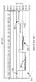
더욱 구체적으로, 위 밴드 조절 어셈블리가 위 밴드를 이식할 때 환자에 배치하기 위하여 제공된다. 어셈블리는 위 밴드의 팽창가능한 부분의 루멘(lumen)에서 압력 판독(pressure reading) 또는 유체 압력 감지를 위해 사용되는 센서를 포함한다. 펌프 어셈블리는 루멘에 접속되며, 펌프 어셈블리를 작동하는 컨트롤러가 제공되어, 압력 판독 및 위 밴드를 위해 정의된 표적 압력(예를 들어, 어셈블리의 메모리에 저장된 밴드의 바람직한 압력)에 기초하여 루멘 내의 유체의 부피를 조절한다. 어셈블리는 압력 판독을 프로세싱하여 표적 압력의 설정을 제공하는 압력 조절 모듈(예를 들어, 컨트롤러에 의해 작동하는 소프트웨어/하드웨어 어플리케이션)을 추가로 포함한다. 이러한 프로세싱은 유체의 부피에 대한 제1 및 제2 값 또는 데이터 범위(즉, 제1 및 제2 충진 레벨 또는 증가분)에서 압력 변동/표준 편차를 결정한 다음, 압력 변동이 낮아지도록, 및 일부 경우에 위 밴드에 대한 미리정의된 최대 압력 변동 값 또는 압력 변동 한계보다 낮아지도록 결정되는 제1 및 제2 값 또는 부피 중 하나에 상응하여 표적 압력을 설정하는 것을 포함할 수 있다. 예를 들어, 압력 변동 한계는 약 0.5 PSI 미만, 0.3 PSI 미만, 또는 훨씬 더 바람직하게 약 0.1 PSI 미만일 수 있으며, 충진 부피는 표적 압력에 상응하도록 설정될 수 있다. 조절 모듈은 밴드가 충진 부피까지 충진된 후 압력 판독을 모니터링하기 위하여, 그리고 압력 변동이 압력 변동 한계를 초과할 때 치료 조건 변화에 자동으로 적응하도록 표적 압력을 조절하기 위하여 더욱 작동할 수 있다. 외부 컨트롤 장치는 컨트롤러와 무선으로 통신하여 표적 압력 및/또는 충진 부피를 변경하고 압력 판독을 검색하도록 사용될 수 있으며, 이는 그래프 형태로 외부 컨트롤 장치의 모니터에 디스플레이되어 밴드 조절 작동시 의사에게 피드백을 제공할 수 있다.More specifically, a gastric band control assembly is provided for placement in a patient when the gastric band is implanted. The assembly includes a sensor used for pressure reading or fluid pressure sensing in the lumen of the inflatable portion of the upper band. The pump assembly is connected to the lumen and a controller is provided to operate the pump assembly to provide fluid reading in the lumen based on the pressure reading and the target pressure defined for the band above (eg, the desired pressure of the band stored in the memory of the assembly). Adjust the volume. The assembly further includes a pressure regulation module (eg, a software / hardware application operated by a controller) that processes the pressure readings to provide a setting of the target pressure. This processing determines the pressure fluctuations / standard deviations in the first and second values or data ranges (ie, the first and second fill levels or increments) for the volume of the fluid and then lowers the pressure fluctuations, and in some cases And setting the target pressure corresponding to one of the first and second values or volumes determined to be below a predefined maximum pressure fluctuation value or pressure fluctuation limit for the band. For example, the pressure fluctuation limit may be less than about 0.5 PSI, less than 0.3 PSI, or even more preferably less than about 0.1 PSI, and the fill volume may be set to correspond to the target pressure. The conditioning module may further operate to monitor the pressure reading after the band has been filled to the fill volume and to adjust the target pressure to automatically adapt to changes in treatment conditions when the pressure change exceeds the pressure change limit. The external control unit can be used to communicate wirelessly with the controller to change the target pressure and / or fill volume and retrieve the pressure reading, which is displayed in the form of a graph on the monitor of the external control unit to provide feedback to the physician during band adjustment operation. can do.
본 발명의 다른 태양에 따르면, 위 밴드의 팽창가능한 부분에 유체의 부피를 조절하는 방법이 제공된다. 환자에, 위 밴드를 이식하거나 또는 팽창가능한 내측 링을 환자의 위 및/또는 식도와 맞물려 스토마를 형성하도록 배치한다. 이 방법은 또한 팽창가능한 내측 링 안의 유체의 압력 판독을 위해 위 밴드와 작동가능하게 연결되는 센서를 제공하는 것을 포함한다. 제1 부피의 유체가 내측 링안으로 주입되고, 센서는 일정 시간동안 작동하여 제1 설정의 압력 판독을 수집한 후, 압력 조절 모듈을 사용하여 제1 설정의 압력 판독을 프로세싱하여 제1 설정의 압력 변동(예를 들어, 표준 편차, 최대와 최소 압력 사이의 차이 등)을 결정한다. 이 방법은 추가량의 유체를 내측 링으로 계속 주입하여 위 밴드에 제2 부피의 유체를 제공한다. 그리고 나서, 센서를 작동시켜 제2 설정의 압력 판독을 모으고 압력 조절 모듈은 이러한 압력 판독을 프로세싱하여 제2 설정의 압력 변동을 결정한다. 이 방법은 제1 및 제2 설정의 압력 변동을 압력 변동 한계와 계속 비교한다. 그 다음, 어떤 것이 압력 변동 한계보다 작은 압력 변동을 갖는 가에 따라 제1 또는 제2 부피와 동일하거나 근사치인 위 밴드용 충진 부피를 설정한다. 두 부피가 모두 압력 변동 한계보다 작은 압력 변동을 갖는 경우, 방법은 추가량의 유체를 내측 링에 증가시켜 주입한 다음 센서를 작동, 압력 변동 결정, 압력 변동 한계와 비교, 및 압력 변동 한계를 초과할 때까지 충진 부피를 설정하는 단계를 반복하는 것을 포함할 수 있다. 이러한 방법은 충진 라인에 의해 내측 링에 접속되는 엑세스 포트에 또는 그 근처에 제공되는 압력 센서를 사용하여 내부 밴드 조절 시스템에 의해 또는 외부 컨트롤러에 의해 실시할 수 있다.According to another aspect of the invention, a method is provided for adjusting the volume of a fluid in the inflatable portion of the upper band. In the patient, a gastric band is implanted or the inflatable inner ring is placed to engage the patient's stomach and / or esophagus to form a stroma. The method also includes providing a sensor operably connected with the upper band for pressure reading of fluid in the inflatable inner ring. The first volume of fluid is injected into the inner ring, the sensor operates for a period of time to collect the pressure reading of the first setting, and then uses the pressure regulation module to process the pressure reading of the first setting to Determine the variation (eg, standard deviation, difference between maximum and minimum pressure, etc.). This method continues to inject an additional amount of fluid into the inner ring to provide a second volume of fluid to the upper band. The sensor is then activated to collect the pressure readings of the second set and the pressure regulation module processes these pressure readings to determine the pressure variation of the second set. This method continuously compares the pressure fluctuations of the first and second settings with the pressure fluctuation limits. The filling volume for the upper band is then set equal to or close to the first or second volume depending on which has a pressure variation less than the pressure variation limit. If both volumes have pressure fluctuations that are less than the pressure fluctuation limit, the method adds an additional amount of fluid to the inner ring to inject and then operates the sensor, determines the pressure fluctuations, compares the pressure fluctuation limits, and exceeds the pressure fluctuation limits. And repeating the step of setting the fill volume until This method may be carried out by an internal band adjustment system or by an external controller using a pressure sensor provided at or near the access port connected to the inner ring by the filling line.
본 발명의 다른 태양에 따르면, 밴드의 직경 또는 둘레를 조절하고 유체, 기체, 젤 또는 고체로 채워지고 밴드의 내측 표면을 라이닝하는 쉘 내의 압력을 모니터링하는 방법이 제공된다. 밴드의 직경 또는 둘레를 기계적으로 또는 다른 수단에 의해서 변경함으로써, 유체로 채워진 쉘 내부에서 압력의 변화가 실현된다. 상기한 바와 같이, 압력 변동이 시간에 따라 모니터링하여, 밴드 직경을 조절할 때, 변동의 최대설정한계 미만으로 밴드 크기를 설정(예를 들어, 둘레 또는 직경 크기를 설정)하도록 모니터링 또는 분석한다. 컨트롤러, 압력 조절 모듈, 및 외부 컨트롤러 또는 모니터링 장치 및 다른 특징의 다른 실시형태를 사용하는 것이 적어도 일부 경우에 이러한 본 발명의 태양에 적용가능하다.According to another aspect of the present invention, there is provided a method of adjusting the diameter or circumference of a band and monitoring the pressure in the shell filled with fluid, gas, gel or solid and lining the inner surface of the band. By changing the diameter or circumference of the band mechanically or by other means, a change in pressure is realized inside the shell filled with the fluid. As noted above, pressure fluctuations are monitored over time and monitored or analyzed to set the band size (eg, set a circumference or diameter size) below the maximum set limit of the fluctuations when adjusting the band diameter. The use of controllers, pressure regulation modules, and other embodiments of external controllers or monitoring devices and other features is applicable to this aspect of the invention in at least some cases.
본 발명의 다른 태양에 따라, 상기 데이터를 자가 분석하기 위한 방법이 유압 조절되는 위 밴드와 연결하여 사용되는 수동 엑세스 포트에 적용될 수 있다. 이러한 실시형태에서, 압력 센서는 엑세스 포트 내에 또는 모니터링시 시스템 유체 경로 내에 배치되고(센서는 시린지 또는 시린지 어댑터에 배치될 수 있다), 외부 핸드헬드(또는 데스크 탑 등) 컨트롤러로부터의 데이터를 원격으로 쿼리하는 데 사용된다. 밴드는 수동 니들 및 시린지를 사용하여 조절하고(자동화된 내부 조절 시스템에 의해서 조절하는 것에 더하여 또는 그를 대신하여), 압력 데이터는 일부 경우에 충진 부피 증가시 수집된다. 외부 또는 "원격" 컨트롤러는 압력 변동에 대한 데이터를 분석하고 데이터 분석에 기초하여 조정하는 의사에게 최적 충진 부피를 표시(예를 들어, 감지된 압력 및 결정된 압력 변동의 분석에 기초하여 특정 밴드/충진 라인/포트 디자인에 대한 감지된 압력, 결정된 압력 변동 및/또는 계산된 충진 부피를 디스플레이하여)하는 프로세싱 모듈(들)을 포함한다. 앞서 언급한 바와 같이, 이러한 데이터는 엑세스 포트에 대한 이상적인 압력 설정을 표시하도록 그래프로 및/또는 수치로 컨트롤러 상에 디스플레이할 수 있다.According to another aspect of the invention, a method for self-analyzing the data may be applied to a passive access port used in conjunction with a hydraulically controlled upper band. In such embodiments, the pressure sensor is placed in the access port or in the system fluid path upon monitoring (the sensor can be placed in a syringe or syringe adapter) and remotely retrieves data from an external handheld (or desktop, etc.) controller. Used to query. The band is adjusted using manual needles and syringes (in addition to or in place of the adjustment by an automated internal conditioning system), and pressure data are collected in some cases upon filling volume increase. An external or "remote" controller analyzes the data for pressure fluctuations and displays the optimal fill volume to the physician who adjusts based on the data analysis (e.g. specific band / fill based on analysis of detected pressures and determined pressure fluctuations) Processing module (s) for displaying the sensed pressure, determined pressure variation and / or calculated fill volume for the line / port design). As mentioned above, this data can be displayed on the controller graphically and / or numerically to indicate the ideal pressure setting for the access port.
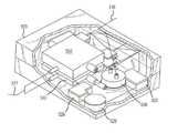
도 1은 환자 내에 설치될 때 보이는 것과 같은 본 발명에 따른 자가-조정(즉, 자가-모니터링 및 자가-조절) 위 밴드 시스템을 나타낸다.1 shows a self-regulating (ie self-monitoring and self-regulating) gastric band system according to the present invention as seen when installed in a patient.
도 2는 도 1의 시스템에서와 같이 자가-조정 위 밴드 시스템에 사용될 수 있는 것과 같은 밴드의 루멘과 유체 연결된 상호접속된 내부 밴드 조절 시스템을 갖는 위 밴드를 나타낸다.FIG. 2 shows the upper band with an interconnected inner band adjustment system in fluid communication with the lumen of the band as may be used in a self-tuning upper band system as in the system of FIG. 1.
도 3은 위 밴드의 내경 또는 크기 및 내측, 팽창가능한 루멘을 팽창(및 감소 및 수축)하는 데 사용하기 위한 유체를 위한 국소 또는 내부 저장소를 제공하는 외측 루멘의 미세 튜빙을 위해 사용된 내측, 팽창가능한 루멘에 표시된 선 3-3에서 취한 도 2의 위 밴드의 단면도이다.FIG. 3 shows the inner, expanded, and inner diameters of the upper band and the inner, expanded used for fine tubing of the outer lumen providing a local or internal reservoir for use in expanding (and reducing and contracting) the expandable lumen. A cross sectional view of the upper band of FIG.
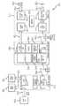
도 4는 본 발명의 일 실시형태에 따른 자가-조정 밴드 시스템의 기능 블록 다이어그램이다.4 is a functional block diagram of a self-tuning band system in accordance with an embodiment of the present invention.
도 5는 본 발명의 자가-조정 기능을 수행하는 데 유용한 펌프 어셈블리의 일 실시형태를 더욱 구체적으로 나타내는 본 발명의 자가-조정 위 밴드 시스템의 다른 실시형태의 개념 및/또는 기능 블록 다이어그램이다.FIG. 5 is a conceptual and / or functional block diagram of another embodiment of the self-regulating upper band system of the present invention in more detail an embodiment of a pump assembly useful for performing the self-tuning function of the present invention.
도 6은 본 발명의 펌프 어셈블리,구체적으로, 도 5의 시스템의 펌프 어셈블 리의 한가지 물리적 실현의 부분분해 사시도이다.6 is a partially exploded perspective view of one physical realization of the pump assembly of the present invention, specifically, the pump assembly of the system of FIG.
도 7은 도 5의 시스템과는 상이한 펌프 어셈블리를 사용하는 본 발명의 자가-조정 위 밴드 시스템의 다른 실시형태를 나타내는 도 5와 유사한 개념 다이어그램이다.7 is a conceptual diagram similar to FIG. 5 showing another embodiment of the self-adjusting upper band system of the present invention using a pump assembly different from the system of FIG. 5.
도 8은 도 5 및 도7의 시스템에 나타낸 것과는 상이한 펌프 어셈블리를 사용하는 본 발명의 자가-조정 위 밴드 시스템의 또 다른 실시형태를 나타내는 도 5 및 도 7과 유사한 개념 다이어그램이다.FIG. 8 is a conceptual diagram similar to FIGS. 5 and 7 showing another embodiment of the self-tuning upper band system of the present invention using a pump assembly different from that shown in the systems of FIGS. 5 and 7.
도 9는 본 발명의 조절 특징을 실시하는 데 유용한 여전히 다른 펌프 어셈블리를 사용하는 본 발명의 자가-조정 위 밴드 시스템의 또 다른 실시형태를 나타내는 도 5, 도 7 및 도 8과 유사한 개념 다이어그램이다.FIG. 9 is a conceptual diagram similar to FIGS. 5, 7 and 8 showing another embodiment of the self-adjusting upper band system of the present invention that still uses another pump assembly useful for practicing the adjustment features of the present invention.
도 10은 시스템 펌프 어셈블리를 사용하는 본 발명의 자가-조정 위 밴드 시스템의 또 다른 실시형태 및 도 5, 도 7, 도 8 및 도 9의 시스템에 관한 센서위치를 나타내는 도 5, 도 7, 도 8 및 도 9와 유사한 개념 다이어그램이다.FIG. 10 shows another embodiment of the self-adjusting upper band system of the present invention using a system pump assembly and sensor positions relative to the system of FIGS. 5, 7, 8 and 9. Conceptual diagram similar to 8 and FIG. 9.
도 11은 전화 링크를 통해 원격 컨트롤러 또는 서비스(예를 들어, 웹-페이지 기반 컨트롤러 또는 서비스)와 통신하는 핸드헬드 컨트롤러를 사용한 본 발명의 자가-조정 또는 조절 위 밴드 시스템의 기능 블록 다이어그램이다.11 is a functional block diagram of the self-tuning or conditioning upper band system of the present invention using a handheld controller in communication with a remote controller or service (eg, a web-page based controller or service) via a telephone link.
도 12는 도 11의 시스템의 핸드헬드 컨트롤러 및 크래들을 더욱 상세하게 나타내는 다른 기능 블록 다이어그램이다.12 is another functional block diagram illustrating the handheld controller and cradle of the system of FIG. 11 in greater detail.
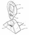
도 13 및 14는 도 10 및 도 11의 시스템을 수행하기 위한 것과 같은, 본 발명에 따른 헨드헬드 컨트롤러 및 크래들의 예시적인 실시의 사시도이다.13 and 14 are perspective views of an exemplary implementation of a handheld controller and cradle in accordance with the present invention, such as for performing the system of FIGS. 10 and 11.
도 15는 도 10 및 도 11에 나타낸 것과 같이, 정상 모드로 작동하여 이식가능한 위 밴드의 크기를 조정하는 위 밴드 시스템의 순서도이다.FIG. 15 is a flow chart of a gastric band system operating in normal mode to adjust the size of the implantable gastric band, as shown in FIGS. 10 and 11.
도 16은 소프트웨어 어플리케이션 또는 모듈을 사용하여 자동화된(또는 선택적으로 수동으로 착수되는) 위 압력 컨트롤을 나타내는 본 발명의 다른 실시형태에 따른 도 4의 시스템과 유사한 자가-조정 위 밴드 시스템의 기능 블록 다이어그램이다.FIG. 16 is a functional block diagram of a self-adjusting upper band system similar to the system of FIG. 4 in accordance with another embodiment of the present invention showing gastric pressure control automated (or optionally manually initiated) using a software application or module. to be.
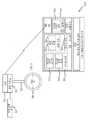
도 17은 엑세스 포트에 또는 그 근처에 압력 센서가 제공되고 위 밴드의 충진을 조절하기 위한 외부 컨트롤 장치에 의해 압력 분석 및 조절 모듈이 사용되는 본 발명의 다른 실시형태에 따른 위 밴드 시스템을 나타내는 도 16과 유사한 블록 다이어그램이다.FIG. 17 illustrates an upper band system according to another embodiment of the present invention in which a pressure sensor is provided at or near the access port and a pressure analysis and regulation module is used by an external control device for adjusting filling of the upper band. A block diagram similar to 16 is shown.
도 18은 이력(historical)이거나 디스플레이 실시간으로 제공될 수 있는 위 밴드 압력 데이터의 그래프를 나타낸다.18 shows a graph of upper band pressure data that may be historical or provided in display real time.
관련 실시형태의 상세한 설명Detailed Description of the Related Embodiment
간단히, 본 발명은 환자에 이식 전 또는 후에 조작자(예를 들어, 의사 또는 전문가)가 위 밴드에 대한 작동 파라미터를 설정할 수 있는 자가-조정 위 밴드 또는 밴드 시스템에 관한 것이다. 그리고 나서, 자가-조정 위 밴드를 위 밴드의 특성 및 관련된 특성을 직접 모니터링하도록 작동하여 이러한 모니터링된 또는 감지된 특성이 설정 작동 파라미터 또는 경계 이내 인지 결정하고, 그 후, 경계 이내가 아니라면, 자동적으로 위 밴드의 크기(즉, 환자의 위의 스토마의 크기를 정하는 이의 내경)를 조절하여 모니터링된 또는 감지된 특성 또는 특성들이 본 작동 범위 또는 경계 이내가 되도록 할 수 있다.Briefly, the present invention relates to a self-adjusting gastric band or band system in which an operator (eg, a doctor or specialist) can set operating parameters for the gastric band before or after implantation in a patient. The self-tuning upper band is then operated to directly monitor the upper band's characteristics and associated characteristics to determine if these monitored or detected characteristics are within set operating parameters or boundaries, and then automatically, if not within the boundaries. The size of the gastric band (ie, its internal diameter which determines the size of the stomach of the patient's stomach) may be adjusted to ensure that the monitored or detected characteristic or characteristics are within this operating range or boundary.
본 발명의 자가-조정 위 밴드 시스템은 포함된 유체의 부피를 증가 또는 감소시켜 팽창 또는 수축되는 팽창가능한 부분 또는 내측 루멘을 포함하는 것들에 유용한 특히 유용한 많은 실시형태에서 일반적으로 많은 위 밴드 디자인에 사용될 수 있다. 일반적으로, 본 발명의 위 밴드 시스템은 밴드 파라미터, 예를 들어, 팽창가능한 부분 내의 유체의 압력을 직접 감지하기 위한 하나 이상의 센서, 및 이러한 감지된 밴드 파라미터 또는 특성을 프로세싱하여 밴드에서 유체를 추가할 지 뺄지를 결정하여 미세하게 그 크기(및 상응하는 스토마 크기)를 조율하는 컨트롤러를 포함한다. 펌프 어셈블리와 접속되는 국소 유체 저장소가 제공되며, 이는 유체를 밴드 내로 또는 밖으로 펌핑하도록 컨트롤러에 의해 컨트롤된다. 일 실시형태에서, 국소 유체 저장소는 위 밴드 자체 안에, 예를 들어, 외측 루멘 또는 저장소 링 또는 부재에 제공된다. 내측 충진 라인 또는 튜브는 (예를 들어, 표준 엑세스 포트 대신에 또는 그에 더하여) 부피가 국속적으로 컨트롤되도록 펌프 어셈블리와 위 밴드의 팽창가능한 부분 또는 부재 사이를 연결한다. 펌프 어셈블리, 컨트롤러, 및 센서를 위한 전력은 또한 전형적으로 위 밴드에 국소 제공되며, 즉, 유도 전원과 같은 외부 전원보다는 체내에 또는 환자의 스토마 및 위 밴드에 인접하여 제공된다. 메모리는 또한 밴드 데이터 및 언제 위 밴드의 크기를 조절할 지를 결정하는 데 사용되는 밴드 작동 범위 또는 경계를 저장하기 위하여 컨트롤러와 관련되며, 이러한 작동 범위 또는 경계(즉, 범위 한계)는 이식 전에 설정되거나 또는 그 후 설정될 수 있고, 또는 외부 컨트롤러/모니터와 통싱하여 변경될 수 있다. 본 발명의 이러한 및 다른 특징이 도 1-10을 참조하여 하기 기재에 상세히 설명된다.The self-adjusting gastric band system of the present invention is generally used in many gastric band designs in many particularly useful embodiments that are useful for those that include an expandable portion or an inner lumen that expands or contracts by increasing or decreasing the volume of fluid contained therein. Can be. Generally, the above band system of the present invention processes one or more sensors for directly sensing the pressure of a fluid in a band parameter, e. And a controller that finely tunes its size (and corresponding storm size) by determining whether to subtract it. A local fluid reservoir is provided in connection with the pump assembly, which is controlled by the controller to pump fluid into or out of the band. In one embodiment, the local fluid reservoir is provided in the upper band itself, for example in the outer lumen or reservoir ring or member. The inner fill line or tube connects between the pump assembly and the expandable portion or member of the upper band such that volume is controlled locally (eg, instead of or in addition to a standard access port). Power for the pump assembly, controller, and sensor is also typically provided locally to the stomach band, i.e., within the body or adjacent to the patient's story and stomach band rather than an external power source such as an induction power source. The memory is also associated with the controller to store band data and band operating ranges or boundaries used to determine when to scale the upper band, such operating ranges or boundaries (ie range limits) may be set prior to implantation or It can then be set, or can be changed in communication with an external controller / monitor. These and other features of the invention are described in detail in the following description with reference to FIGS. 1-10.
도 1은 병적 비만을 치료하는 환자에 설치시 보이는 것과 같은 자가-조정 위 밴드 시스템 또는 장치(100)를 나타낸다. 나타낸 바와 같이, 시스템(100)은 음식물 섭취 및 흐름을 제한하기 위하여 식도 근처 위의 상부에서 스토마 또는 더 작은 개구를 형성하는 데 사용되고 있다. 환자를 적절히 치료하기 위하여 스토마의 크기를 변경하는 것이 종종 유용하거나 심지어 필수적이다. 따라서, 자가-조정 위 밴드 시스템(100)은 감지된 밴드 파라미터 및 작동 파라미터(예를 들어, 상한 및 하한으로 설정되는 작동 파라미터의 범위)에 기초하여 그 크기를 자가-조정하는 데 적합하다. 위 밴드 시스템(100)은 엑세스 포트(114)와 접속되어 유체가 이를 통해 위 밴드(110)의 팽창가능한 부분 또는 부재로 펌핑될 수 있는 충진 튜브 또는 라인(112)를 통한 외부 또는 체외 작용에 의해 팽창가능한 위 밴드(110)를 포함한다.이러한 충진은 전형적으로 의사 또는 다른 전문가에 의해 행해지는 이식 프로세스의 일부로서 스토마의 초기 크기설정의 일부으로서 실시될 수 있다.1 shows a self-adjusting gastric band system or
밴드(110) 및 시스템(100)의 다른 구성요소들은 현존하는 확장형 또는 팽창가능한 위 밴드에 사용되는 것과 동일한 또는 유사한 외과 수술로 이식된다. 예를 들어, 외과의사는 전형적으로 위 둘레의 조직을 절개하여 밴드(110)를 위한 터널을 생성한다. 그리고 나서, 밴드(110)를 예를들어, 18 mm 또는 다른 크기의 트로카 등을 통해, 또는 피부의 트로카 구멍을 통해 직접 환자의 복부에 넣는다. 그 다음, 밴드(110)를 터널에 넣고 위 둘레에 배치한다. 내부 밴드 조절 시스템 또는 유 닛(130)을 포함하는 시스템(100)의 다른 구성요소은 충진/배출 라인(120)을 통해 위 밴드(110), 특히 밴드(110)의 팽창가능한 또는 확장가능한 부재 또는 부분에 유체 접속을 제공하면서 위의 근처에(예를 들어, 흉골 위의 피부 바로 아래에 또는 엑세스 포트 근처 직근 시스(sheath) 상에) 배치된다(밴드(110)가 또한 밴드(110)의 크기를 설정하는 데 사용되는 국소 유체 저장소를 포함하는 실시형태에서 추가적인 접속이 제공된다). 다른 실시형태에서, 밴드(110)에 대한 다른 접속이 필요하지 않도록 충진 라인(112)에 접속(120)이 제공된다.The
자가-조정 위 밴드 시스템(100)은 팽창가능한 또는 확장가능한 부분 또는 루멘 내의 또는 충진 라인(112) 내의 유체 압력 또는 밴드 상의 표면 장력/스트레인과 같은 특성 등과 같은 밴드 파라미터를 감지하여 이러한 감지된 또는 모니터링된 밴드 특성 또는 파라미터가 미리정의된 허용가능한 밴드 작동 범위 이내인지를 결정하고, 그렇지 않다면, 위 밴드(110)의 크기를 조절하는 기능을 하는 내부 밴드 조절 어셈블리 또는 유닛(130)을 포함한다. 전형적으로, 크기 조절은 밴드(110)에서 액체를 첨가하거나 빼서 충진/배출 라인(120)을 통해 달성되며, 이는 도 4-10을 참조하여 상세하게 설명한다. 시스템(100)은 내부 밴드 조절 시스템 또는 유닛(130)과의 무선 통신(153)을 통해 입수된 데이터를 디스플레이하는 데, 내부 시스템(100)에 전송할 새로운 작동 파라미터와 같은 데이터를 디스플레이하는 데, 또는 위 밴드(110)와 관련된 이력 데이터 또는 다른 데이터를 디스플레이하는 데 사용되는 디스플레이 요소(154)를 포함하는 외부 모니터링 또는 컨트롤 장치(150)를 추가로 포함한다. 외부 모니터링 장치(150)는 또한 조작자가 데이터를 넣거나 입력 할 수 있는 키패드 또는 다른 입력 영역(156)을 포함한다(예를 들어, 내부 시스템(130)으로부터 데이터를 요청하기 위해서, 작동 범위 조절에 의한 위 밴드(110)를 위한 새로운 설정을 입력하기 위해서 등).Self-adjusting
위 밴드(110)는 본 발명을 실시하기 위하여 많은 형태를 취할 수 있다. 예를 들어, 이에 한정되는 것은 아니지만, 위 밴드(110)는 본 명세서에 참고로 포함되어 있는 미국특허 제5,226,429호 및 제5,601,604호에 기재된 위 밴드와 유사하게 구성될 수 있다. 대안적으로, 위 밴드(110)는 알러간, 인코포레이티드로부터 입수가능한 위 밴드 중 하나를 포함할 수 있다(예를 들어, 9.75, 10.0, 11.0 cm, VG, 또는 AP LAP-BAND와 같은 팽창가능한 위 밴드의 LAP-BAND™ 계열의 밴드 중 하나). 본 발명에 사용할 수 있는 다양한 밴드 제조사/판매처로부터의 다른 위 밴드에는 옵테크 에치콘 밴드(Obtech (Ethicon) band), AMI 밴드, 헬리오가스트(Heliogast) 밴드, 미니마이저 (피어(Pier)) 밴드, 및 쿠션 바이오밴드(Cousin Bioband)가 포함되나 이에 한정되지는 않는다.The
도 2 및 도 3은 본 발명을 실시하는 데 사용될 수 있는(예를 들어, 시스템(100)의 밴드(110)로 사용하는) 하나의 예시적인 위 밴드(210)를 포함하는 자가-조정 위 밴드 어셈블리(200)의 실시형태를 나타낸다. 도 1과 관련하여 설명한 바와 같이, 그리고 도 4-10으로 더욱 상세하게 설명한 바와 같이, 위 밴드 어셈블리(200)는 위 밴드(210) 및 일반적으로 밴드(210)의 특성을 직접 감지하기 위한 센서(들)을 포함하는 내부 조절 시스템(230), 메모리가 있는 컨트롤러, 내부 전력 공급기, 및 펌프 어셈블리(도 2 및 3에는 도시하지 않았으나 도 4-10에서 설명함)을 포함한다.2 and 3 are self-tuning stomach bands that include one
위 밴드(210)는 엑세스 포트(도시안함)와 밴드(210)의 팽창가능한 또는 확장가능한 부분 또는 루멘(226) 사이에 유체 접속을 제공하는 데 사용되는 충진 튜브 또는 라인(212)을 포함한다. 오목한 표면(215) 및 볼록한 부분(218)을 갖는 벨트(214)가 버클 부재(216)를 따라 제공되어 밴드(210)를 환자의 위 주변에 이식하여 스토마의 안쪽 크기를 제공할 때 특정한 안쪽 크기 또는 내경의 원형 루프 또는 밴드를 형성할 수 있다(예를 들어, 밴드의 크기를 9 내지 11 cm 또는 다른 유용한 내경으로 초기에 설정하기 위하여). 스토마의 추가적인 미세 조절을 가능하게 하기 위하여, 위 밴드는 위의 외표면에 접하는 팽창가능한 부분 또는 부재를 포함한다.The
나타낸 바와 같이, 위 밴드(210)는 쉘 또는 주조된 쉘(220), 내측 링(222), 및 탄성 또는 다른 재료로 된 크기를 크게 했다가 작게 할 수 있는 팽창가능한 부분, 부재 또는 풍선(224)을 포함한다. 팽창가능한 부재(224)는 들어간 부피의 유체, 예를 들어, 염수 등을 위한 내부 루멘(226)을 포함한다. 본 발명의 한가지 특징에 따르면, 위 밴드(210)는 팽창가능한 부분(224)을 팽창하거나 수축하기 위한 유체를 저장하기 위한 국소 유체 저장소를 제공하도록 구성될 수 있다. 이와 관련하여, 전형적으로 팽창가능한 부재(224)보다 더욱 경질의 재료로 제조되고 321에서 쉘(220)에 부착되는(예를 들어, 접착제를 사용) 내측 링(222)은 나중에 내부 조절 시스템(230)에 의하여 팽창가능한 부분(224)의 루멘(226)으로 펌핑될 수 있는 유체를 저장하기 위한 루멘 또는 저장소(323)를 포함한다. 저장소 접속 튜브 또는 라인(238)이 내부 밴드 조절 시스템(230)에(예를 들어, 시스템(230)의 펌프(도시하지 않음)로) 제공되기 때문에 루멘 또는 저장소(323)가 유체의 저장에 유용하다.As shown, the
내측 링(222)에 의해 형성된 저장소(323)를 나온 유체는 내부 밴드 조절 시스템(230)에 의해서 라인(340)을 통해 팽창가능한 부재(224)의 루멘(226)으로 펌핑되어 위 밴드의 크기를 증가시키거나(즉, 도 3에 도시된 바와 같이 밴드(210)의 단면의 외경을 증가시킴), 또는 위 주위의 밴드에 의해 형성된 ID의 크기를 감소시켜 환자에 형성된 스토마의 크기를 감소시킨다. 다른 때에, 내부 조절 시스템(230)이 작동하여(감지된 밴드 파라미터에 기초하여) 유체를 화살표(350)로 표시함 바와 같이 루멘(226)으로부터 팽창가능한 부분(224)의 루멘(226)과 접속된 충진/배출 라인(234)를 통해 내부 밴드 조절 시스템(230)으로(또는 시스템(230)의 펌프로) 펌핑한다. 이렇게 루멘(226)으로부터 유체를 제거하면 밴드(210) 및 팽창가능한 부재(224)의 크기가 감소하는 반면에, 위 주위에 밴드(210)에 의해 형성된 ID가 증가하고 환자 스토마의 크기가 증가한다. 팽창가능한 부분(224)으로부터 제거된 유체는 화살표(340)에 의해 나타낸 바와 같이 저장 및 나중에 위 밴드(210)를 크기설정 및 조절하는 데 사용하기 위해 저장소(323)으로 펌핑된다.Fluid exiting the
도 4는 예시적인 자가-조정 위 밴드 어셈블리 또는 시스템(400)을 형성하는 기능 블록을 나타낸다. 시스템(400)은 내부 밴드 조절 시스템(430)과 무선으로 통신(426)하는 외부 모니터링 및/또는 컨트롤 장치(410)를 포함한다. 사용시, 내부 밴드 조절 시스템(430)은 팽창가능한 또는 조절형 위 밴드(460)를 따라 환자의 복강에 이식되어 환자의 위에 스토마를 형성하여 비만을 처치하며, 즉, 유체의 첨가 또는 배출에 의해 위 밴드가 팽창 또는 수축하여 위 밴드의 크기 및 원형 구조에서 밴드에 의해 형성된 밴드의 내경, IDBAND를 변경한다. 외부 모니터링 및 컨트롤 장치(410)는 정보를 디스플레이하기 위한 디스플레이 요소(412) 및 사용자가 데이터 또는 정보를 입력할 수 있는 및 426으로 나타낸 것과 같이 내부 밴드 조절 시스템(430)의 I/O 구성요소와의 무선 통신을 위한 키패드, 터치스크린 및/또는 음성 데이터 입력 구성과 같은 입력/출력 구성요소(414)를 포함하는 핸드헬드, 랩탑, 또는 데스크탑 컴퓨터 및/또는 통신 장치의 형태를 취할 수 있다. 장치(410)는 예를 들어, 시스템(430)으로부터 읽을 수 있고 내부 시스템(430)의 컨트롤러(432) 및 I/O(434)에 의해 제공될 수 있는 밴드 데이터(418)를 저장하기 위하여, 및 컨트롤 장치(410)에 입력되거나 내부 시스템(410)에 존재할 수 있으며 나중에 메모리(416)에 저장하기 위해 및/또는 외부 컨트롤 장치(410)의 작동의 변경 또는 수정을 위해 외부 장치(410)에 의해 읽혀질 수 있는 위 밴드(460)에 대한 밴드 설정(420), 예를 들어, 작동 범위 또는 경계(즉, 예를 들어, 압력 범위의 상한 및 하한)를 저장하기 위해 메모리(416)를 추가로 포함한다. 메모리(416)는 또한 내부 밴드 조절 시스템(430)의 센서(450)에 의해서 얻어진 센서 데이터(422)(및 일부 경우에 환자 데이터)를 저장하기 위한 외부 컨트롤 장치(410)에 의해 사용될 수 있다.4 illustrates a functional block forming an exemplary self-tuning upper band assembly or
내부 밴드 조절 시스템(430)은 시스템(430)의 작동을 컨트롤하는 데 유용한 CPU 및 코드를 포함할 수 있는 컨트롤러(432)를 포함하는 것으로 나타나 있다. 시스템은 외부 모니터링 및 컨트롤 장치(410)와 통신하기 위한 I/O 요소(434)를 추가로 포함한다. 메모리(436)가 밴드 설정(438), 즉, 센서(450)에 의해 감지되는 위 밴드(460)의 특별한 특성 또는 파라미터에 대한 허용가능한 작동 범위, 예를 들어, 센서(450)가 위 밴드(460)의 팽창가능한 부분을 위한 유체에 대한 압력 센서인 경우 압력 상한 및 하한(예를 들어, 4 및 5 PSI)의 저장을 위해 시스템(430)에 제공된다. 밴드 설정(438)은 시스템(430)을 환자에 이식하기 전에 특정 환자에 대해 설정되거나 기본 설정으로 설정될 수 있으며, 및/또는 밴드 설정(438)은 이식 후에 외부 모니터링/컨트롤 장치(410)를 통해 위 밴드(460)의 크기 및 그에 따른 내경, IDBAND를 변경하도록 설정 또는 수정될 수 있다. 메모리(436)가 또한 다른 센서 및 밴드 데이터(440), 예를 들어, 위 밴드(460) 작동의 이력 조망(historical perspective)을 제공하기 위하여 센서(450)로부터 수집된 데이터 및 밴드 일련 번호, 제조사 등과 같은 밴드 정보를 저장하기 위해 컨트롤러(432)에 의해 사용된다.The inner
위 밴드(460)의 작동을 모니터링하기 위하여, 시스템(430)은 바람직하게는 위 밴드(460)의 특성 또는 물리적 파라미터를 직접 모니터링하는 센서(450)를 포함한다. 나타낸 바와 같이, 센서(450)는 위 밴드(460)과 시스템(430)의 펌프 어셈블리(442) 사이의 유체 링크 또는 접속(448)에서 452에 나타낸 바와 같이 압력 변환기(transducer) 또는 다른 장치에 제공되거나 이와 링크될 수 있다. 대안적으로, 압력 변환기 또는 다른 압력 감지 장치는 센서(450)로서 제공되거나 또는 예를 들어, 밴드(460)의 팽창가능한 부분에, 밴드(460)에 대한 유입 포트에, 엑세스 포트(474) 및 외부 충진 장치(470)와 통하는 충진 라인(478)에 배치함으로써 센서(450)와 통하여 위 밴드(450) 내의 압력을 측정한다(한편으로, 밴드(460)의 팽 창가능한 또는 확장가능한 부분의 초기 충진을 위해 또는 선택적인 나중의 밴드(460)의 조절을 위해 제공된다). 센서(450)는 또한 선(456)으로 표시한 바와 같이 예를 들어, 팽창가능한 또는 확장가능한 부분의 표면 상의 밴드(460)의 표면 장력을 표시하는 스트레인 센서를 사용하여, 또는 위 밴드(460)의 현재의 크기를 측정하는 데 유용한 다른 감지 장치를 사용하여 밴드(460)의 특성을 달리 직접 감지하도록 배치할 수 있다.In order to monitor the operation of the
센서(450)는 밴드(460)의 파라미터가 미리설정된 범위를 벗어난 것으로 감지될 때(예를 들어, 최대 설정 초과 또는 최저 설정 미만), 센서(450)가 컨트롤러(432)를 "깨워(wake up)" 펌프 어셈블리(442)를 작동시킬 수 있도록 밴드 설정(438)을 저장하기 위한 메모리(436)를 포함한다. 환언하면, 센서(450)는 언제 위 밴드(450)가 미리설정된 작동 범위를 벗어날지를 결정하고 감지된 밴드 파라미터를 전송하여 컨트롤러(432)가 밴드(460)를 조절하기에 적합하게 작용할 수 있는 것을 포함하여 컨트롤러(432)가 작동하여 펌프(442)를 컨트롤하도록 경보 또는 알람으로 반응하기에 충분하게 인텔리전트하도록 구성될 수 있다. 대안적으로, 센서(450)는 주기적으로(또는, 일부 경우에, 거의 계속적이도록 더욱 자주) 작동하여 밴드 특성또는 파라미터(452 및 456으로 도시됨)를 추가적으로 판독하고, 감지된 값을 컨트롤러(432)에 제공할 수 있는 한편, 감지된 밴드 값을 밴드 설정(438)과 비교하여 밴드(460)의 조절이 필요한지 또는 바람직한지를 결정할 수 있다.When the
다른 경우에, 컨트롤러(432) 및 시스템(430)의 다른 전력 소모 구성요소(예를 들어, 펌프 어셈블리(442) 및 센서(450))에 전력을 공급하기 위하여 배터리 등 과 같은 전력 공급기(444)가 사용된다. 시스템(430)은 펌프 어셈블리(442) 및 내부 저장소(446)를 추가로 포함한다. 펌프 어셈블리(442)는 센서(450) 정보에 반응하여 밴드(460)의 크기를 유압 조절하도록 다양한 형태(예를 들어, 도 5-10에 도시한 것들)를 취할 수 있으며, 본 발명은 특정한 펌프 또는 유체 이송 장치에 한정되지 않는다. 내부 또는 국소 저장소(446)는 펌프 어셈블리(442)와 유체 연결되며 충진/배출 라인(448)을 통해 밴드(460)로 펌핑하여 그 크기를 증가시키거나 IDBAND를 감소시키기 위한 유체(예를 들어, 염수)를 제공하며 또한 압력 차이에 기초하여 밴드(460)로부터 라인(448) 및 펌프 어셈블리(442)를 통해 펌핑하거나 흐르게 할 수 있는 유체를 저장하기 위한 장소를 제공한다.저장소(446)는 내부 밴드 조절 시스템(430)을 넣거나 둘러싸는 데 사용되는 하우징(도시하지 않음) 내에 별도의 구성요소로서 제공될 수 있으며, 또는 저장소(446)은 시스템(430) 하우징 및 밴드(460) 근처에 제공되는, 예를 들어, 풍선-형 구조의 형태로 별도의 장치로서 제공될 수 있다. 더욱이, 일부 실시형태에서, 저장소(446)는 위 밴드(460) 자체의 일부로서 예를 들어, 밴드 쉘의 외측 루멘 또는 부재에 제공될 수 있다(도 2-3 및 도 5-10에 도시된 바와 같음).In other cases, a
자가-조정 위 밴드 시스템의 일반적인 특징을 이해하는 것이, 이식된 위 밴드(예를 들어, 밴드(110, 210 및 460))의 크기를 효과적으로 조절하기 위한 이러한 시스템의 작동을 더욱 완전하게 논의하는 데 유용할 수 있다. 펌프 어셈블리는 전형적으로 모듈 방식이며 임의의 수의 위 밴드, 예를 들어, 현재 알러간, 인코포레 이티드로부터 입수가능한 것들, 예를 들어, 9.75 cm, 10.0cm, VG, 또는 AP LAP-BAND를 사용할 수 있다. 펌프 어셈블리의 펌프는 수동 조절형 엑세스 포트의 기능을 대체한다. 밴드를 구성하는 데 사용되는 재료는 일반적으로 보통 사용되는 것과 여전히 동일할 것이며, 밴드의 치수는 국소 저장소가 쉘 또는 튜빙에 제공되는 경우의 튜빙을 제외하고는 여전히 동일할 것이다. 그러나, 성능향상을 위해, 내산성 향상을 위해, 또는 일부 다른 바람직한 결과를 달성하기 위해 특별히 선택되는 재료와 같은 대안 재료를 본 발명을 실시하는 데 사용할 수 있다. 유사하게, 외경을 .130 내지 .180 이상 증가시켜 외측 또는 쉘 루멘 또는 튜빙 내의 염수 용량을 증가시켜 추가 조절을 위해 사용될 수 있는 추가적인 염수 또는 유체를 위한 저장소로서 작용하도록 하기 위하여 밴드 튜빙에 약간의 변화가 있을 수 있다. 위 밴드의 튜빙은 저장소용 염수와 밴드의 일부인 염수(도 2 및 3에 도시된 바와 같음)를 분리하기 위하여 2개의 루멘을 가질 수 있다. 또한, 긴 팽창된 풍선을 튜빙을 따라 배치하여 저장소로 작용하도록 할 수 있다. 펌프 어셈블리는 일반적으로 하나 이상의 펌프(또는 유체를 밴드 안팍으로 이동시키기 위한 펌프-형 장치), 전자장비, 통신 구성요소, 컴퓨터 또는 인텔리전스 구성요소, 및 배터리 또는 배터리들과 같은 전력 공급기를 포함할 것이다. 내부 위 밴드 조절 어셈블리는 아세틸 공중합체, PEEK, 티타늄 등과 같은 생체적합성 재료로 된 외측 하우징 내에서 밀봉될 것이다. 일부 실시형태에서, 전력 공급기는 펌프 어셈블리 내에 배치하기 전에 티타늄 내에 밀폐적으로 밀봉된 이식가능한 등급의 배터리이다. 펌프 어셈블리는 도 4에 나타낸 엑세스 포트(474)를 통해 예를 들어 외부 충진 장치(470)를 사용하여 필요시 수동 조절을 가능하게 하는 오버-라이드(over-ride) 포트를 가질 수 있다.Understanding the general characteristics of the self-regulating gastric band system provides a more complete discussion of the operation of such a system to effectively size the implanted gastric band (eg,
일부 바람직한 실시형태에서, 자가-조정 위 밴드 시스템은 자동으로 또는 "자동설정" 장치로서 기능한다. 예를 들어, 시스템은 계속적으로 또는 주기적으로(예를 들어, 매시간, 매일, 매주, 매월, 또는 일부 다른 선택된 모니터링 기간에) 밴드 파라미터 또는 특성을 감지한 다음 예를 들어, 염수 또는 다른 유체를 사용하여 위 밴드를 유압으로 팽창 또는 수축시켜 조절하도록 기능할 수 있다. 일부 경우에, 염수 충진 부피 및 밴드의 충진 버스트(fill burst)에 대한 동일한 또는 유사한 설명이 자가-조정 위 밴드 시스템에 적용될 것이다. 이러한 자가-조정 실시형태에서의 조절은 센서와 연결된 및 컨트롤 전자장비와 연결된 마이크로펌프 또는 펌프의 원격 액츄에이션에 의해 실시된다. 센서는 밴드의 내부 파라미터와 같은 밴드의 파라미터 또는 특성, 예를 들어, 내부 밴드 압력, 또는 내부 또는 외부 파라미터, 예를 들어, 쉘의 응력 및/또는 스트레인을 직접 검출한다. 센서는 또한 밴드 또는 밴드의 팽창가능한 부분의 길이 변화를 검출하는 선형 동작 센서를 이렇게 검출된 길이 데이터를 스토머 또는 밴드 직경 측정치로 변환하도록 작용하는 센서 또는 컨트롤러와 함께 포함할 수 있다. 센서는 또한 두 지점 사이의 거리를 검출하여 위치 변화를 검출하는 거리 센서일 수 있다. 센서는 외부 모니터링 또는 컨트롤 유닛에 의해 원격측정(telemetry)을 통해 쿼리되어 임상학자의 실시간 피드백을 위해 모니터링되는 파라미터에 데이터를 모을 수 있다.In some preferred embodiments, the self-tuning upper band system functions automatically or as an "autoconfiguration" device. For example, the system can detect band parameters or characteristics continuously or periodically (eg, hourly, daily, weekly, monthly, or some other selected monitoring period) and then use, for example, saline or other fluids. To expand or contract the upper band by hydraulic pressure. In some cases, the same or similar description of the brine fill volume and the fill burst of the bands will apply to the self-tuning stomach band system. In this self-regulating embodiment the adjustment is effected by a remote actuation of the micropump or pump connected with the sensor and with the control electronics. The sensor directly detects the band's parameters or characteristics, such as the band's internal parameters, for example internal band pressure, or internal or external parameters, for example stress and / or strain of the shell. The sensor may also include a linear motion sensor that detects a change in length of the band or inflatable portion of the band, along with a sensor or controller that acts to convert the detected length data into a streamer or band diameter measurement. The sensor may also be a distance sensor that detects a change in position by detecting a distance between two points. Sensors can be queried via telemetry by external monitoring or control units to collect data on monitored parameters for real-time feedback from clinicians.
일부 경우에, 센서는 간격을 두고(또는 모니터링 기간에) "깨어나(wake up)"파라미터를 모니터링하고 테스트를 통해 확립된 또는 장기간의 치료기간에 걸쳐 환 자를 더 잘 치료하기 위해 확립된 이상적인 밴드 파라미터(들)로 밴드를 조절하도록 프로그래밍된다. 파라미터가 이상적인 범위 이내가 아닌 경우, 센서는 밴드가 이상적인 파라미터 컨트롤 한계 이내에 드는 것을 보장하는 데 필요한 만큼 재-조절하도록 명령을 송신할 것이며, 또는 대안적으로, 센서는 밴드로부터 모아진 정보를 밴드가 원하는 작동 범위 이내인지를 결정하는 데 사용하는 컨트롤러로 단순히 보낼 것이다. 예를 들어, 센서는 "깨어나서" 밴드가 "X psi"의 내부 밴드 압력을 모니터링할 지를 결정하고 미리설정된 밴드 파라미터와의 비교에 기초하여 내부 유체 압력이 작동 범위 또는 이 범위 내의 임의의 압력 이내의 중간점의 압력일 수 있는 "Y psi"가 되도록 밴드를 조절할 필요가 있는 지를 결정한다. 센서는, 이러한 구성에서, 컨트롤러와 통신하여 컨트롤러가 이식된 펌프를 활성화하게 할 것이며, 예를 들어, 센서가 범위에 속하는 또는 본 작동 범위의 중간점(또는 센서 및 컨트롤러와 관련된 메모리에 저장된 다른 재설정점)에 맞는 밴드 내의 내부 유체 압력을 검출할 때까지 펌프를 작동하여, 센서가 이상적인 파라미터 한계 이내를 판독할 때까지 밴드 안으로 또는 밴드 밖으로 펌핑될 유체의 부피를 명령한다.In some cases, the sensor monitors the "wake up" parameters at intervals (or during the monitoring period) and is an ideal band parameter established to better treat the patient over the established or prolonged treatment period. Programmed to adjust the band (s). If the parameter is not within the ideal range, the sensor will send a command to re-adjust as necessary to ensure that the band falls within the ideal parameter control limits, or alternatively, the sensor may retrieve the information collected from the band. It will simply send it to the controller you use to determine if you are within range. For example, the sensor “wakes up” to determine if the band will monitor the internal band pressure of “X psi” and based on comparison with preset band parameters, the internal fluid pressure is within the operating range or any pressure within this range. Determine if the band needs to be adjusted to be "Y psi" which can be the pressure at the midpoint. In this configuration, the sensor will communicate with the controller to enable the controller to activate the implanted pump, for example, the sensor is within range or at the midpoint of this operating range (or other reset stored in memory associated with the sensor and controller). The pump is operated until it detects an internal fluid pressure within the band, which dictates the volume of fluid to be pumped into or out of the band until the sensor reads within ideal parameter limits.
마이크로펌프(들)은 이식된 배터리 또는 전력 공급기로부터 전력을 끌어와 조절을 가능하게 하며, 포함되는 경우, 컨트롤러가 또한 하나 이상의 체크 밸브가 개방되도록 활성화시킨다(도 5-10 참조). 밴드를 더욱 팽창시키거나 그 크기를 미세하게 증가시기 위하여, 펌프는 유체를 국소 저장소로부터 밴드로 끌어들인다. 밴드를 수축하고 그 크기를 미세하기 감소시키기 위하여, 펌프는 밴드로부터 다시 저장소로 유체를 끌어들일 것이다. 일단 센서가 특정 파라미터 범위 이내를 판독하 면, 밸브가 닫혀 유체 이동을 막을 것이다. 그 다음에는, 전력이 절약되도록 센서가 다시 "깨어날"때까지 펌프 및 센서가 꺼질 것이다. 현재의 밴드에서와 같이, 유체는 쉘을 팽창 또는 수축시켜 스토마의 크기를 컨트롤하는 데 사용될 수 있으나, 이 경우에 크기 변화는 국소 컨트롤 및 국소 유체 저장소를 사용하여 내부적으로 처리된다.The micropump (s) draw power from the implanted battery or power supply to enable regulation, and if included, the controller also activates one or more check valves to open (see FIGS. 5-10). To further inflate the band or increase its size slightly, the pump draws fluid from the local reservoir into the band. In order to shrink the band and to reduce its size, the pump will draw fluid from the band back into the reservoir. Once the sensor reads within a certain parameter range, the valve will close to prevent fluid movement. The pump and sensor will then be turned off until the sensor "wakes up" again to save power. As in current bands, the fluid can be used to control the size of the storm by inflating or contracting the shell, but in this case the size change is handled internally using local control and a local fluid reservoir.
센서로부터 새로운 또는 조절된 파라미터 판독과 같은 파라미터 판독을 외부적으로 모니터링하기 위하여, 임상학자 또는 시스템 조작자는 핸드헬드 또는 다른 크기의 외부 모니터 및 환자 체외의 컨트롤 장치를 사용하여 판독용 센서를 쿼리하거나 가장 최근 저장된 값을 위한 컨트롤러를 쿼리할 수 있다(또는 둘 모두). 외부 모니터 장치 및 엑세스 포트를 제외하고, 시스템은 모니터에 자가-포함되며 자체를 조절한다. 펌프 어셈블리는 밴드 데이터 및 허용가능한 밴드 작동 범위 외에 이식된 위 밴드 및 내부 위 밴드 조절 장치를 포함하는 이식된 장치를 확인하기 위하여 외부 모니터링 및 컨트롤 장치에 의해 원격 판독가능한 일련번호와 같은 다양한 데이터를 저장할 수 있다.To externally monitor parameter readings, such as new or adjusted parameter readings from a sensor, a clinician or system operator may use a handheld or other sized external monitor and patient in vitro control device to query or simulate the reading sensor. You can query the controller for the recently stored values (or both). With the exception of external monitor devices and access ports, the system is self-contained in the monitor and regulates itself. The pump assembly may store various data such as serial numbers remotely readable by an external monitoring and control device to identify implanted devices including implanted gastric band and internal gastric band adjusting device in addition to band data and acceptable band operating range. Can be.
외부 장치는 종종 LCD 디스플레이 및 장치를 작동하기 위한 컨트롤 패널을 특징으로 할 수 있는 핸드헬드 컨트롤 유닛의 형태를 취할 것이다. 핸드헬드는 조작자가 메모리에 밴드 크기, 환자명, 이식 의사, 및 이식일과 같은 중요 정보를 담도록 이식물을 프로그래밍(또는 판독/검출)할 수 있게 하는 일련의 메뉴를 특징으로 할 수 있다. 핸드헬드는 전파를 통해 원격측정으로 센서와 통신할 수 있다. FDA 및 국제적으로 인식되는 통신 밴드(WMTS 402 -405 Mhz)가 일부 실시형태에 사용될 수 있고, 장치가 우연히 엑세스되거나 핸드헬드외의 다른 컨트롤 메카니즘에 의해서 컨트롤될 수 없도록 인증 프로세스가 사용될 수 있다. 원격측정 컨트롤 신호는 대체로 발로부터 또는 아마도 환자에서 멀리 떨어진 곳으로부터 송신할 수 있으며, 전형적으로 환자는 센서를 쿼리하기 위하여 또는 이의 파라미터를 변경하기 위하여 탈의할 필요가 없을 것이다. 조절시, 핸드헬드 외부 모니터링 장치는 바람직하게는 현재 압력 또는 파라미터 데이터, 조절 의사명, 핸드헬드 장치를 사용하여 조절 이력을 자체 메모리에 저장 또는 보존하도록 종종 작동한 날짜(이러한 이력은 내부 조절 시스템에도 또는 시스템에만 저장될 수 있다)와 같은 정보를 판독하고 이식물에 기록할 수 있다. 핸드헬드 장치는 또한 권한이 없는 사람이 장치를 쿼리하는 것을 방지하도록 암호 컨트롤될 수 있다. 시각적 및 청각적 출력을 포함할 수 있는 핸드헬드의 디스플레이는 전형적으로 밴드 조건 또는 물리적 파라미터의 감지된 파라미터를 디스플레이 또는 출력하며, 이러한 파라미터 또는 특성이 압력, 응력, 스트레인, 및/또는 선형 측정치이다.External devices will often take the form of a handheld control unit that may feature an LCD display and a control panel for operating the device. The handheld may feature a series of menus that allow the operator to program (or read / detect) the implant in memory to contain important information such as band size, patient name, transplant physician, and transplant date. The handheld can communicate with the sensor via telemetry through radio waves. FDA and internationally recognized communication bands (WMTS 402-405 Mhz) may be used in some embodiments, and the authentication process may be used such that the device may not be accessed accidentally or controlled by a control mechanism other than a handheld. The telemetry control signal can generally transmit from the foot or perhaps far away from the patient, and typically the patient will not need to unload to query the sensor or to change its parameters. During adjustment, the handheld external monitoring device is preferably operated with the current pressure or parameter data, the name of the control doctor, the date often operated to store or preserve the control history in its own memory using the handheld device. Or can only be stored on the system) and recorded in the implant. The handheld device may also be password controlled to prevent unauthorized persons from querying the device. Display of a handheld, which may include visual and audio output, typically displays or outputs sensed parameters of band conditions or physical parameters, such parameters or characteristics being pressure, stress, strain, and / or linear measurements.
센서 변경 지속시간에 대하여, 센서 쿼리는 전형적으로 단지 몇 초가 걸릴 것이나, 마이크로펌프(들)의 컨트롤은 더 오래, 예를 들어, 압력변화 1 psi당 대략 30초가 걸릴 수 있다. 압력 판독 및 파라미터 범위의 감도한계(resolution)는 양호할 것이며 바람직하게는 수동 시린지 조절에 의해 현재 가능한 것보다는 감도한계가 더 양호할 것이다. 데이터 저장과 관련하여, 적어도 일부의 정보가 이식된 내부 시스템에 직접 저장될 것이다. 데이터 검색을 위하여, 핸드헬드를 사용하여 장치를 쿼리하고 스크린에 데이터, 예를 들어, 일련번호, 환자명, 의사명, 밴드 크기, 충 진 부피, 및 조절 이력을 디스플레이할 수 있다.For the sensor change duration, the sensor query will typically take only a few seconds, but the control of the micropump (s) may take longer, eg approximately 30 seconds per 1 psi of pressure change. The resolution resolution of the pressure reading and parameter range will be good and preferably the sensitivity limit will be better than is currently possible by manual syringe adjustment. With regard to data storage, at least some of the information will be stored directly in the implanted internal system. For data retrieval, the handheld can be used to query the device and display data on the screen, such as serial number, patient name, doctor name, band size, filling volume, and control history.
이식물 시스템의 전원에 관해서는, 상기에 이식된 배터리를 상세하게 언급하였으나, 이식물은 다음과 같은 에너지 요건를 충족시키는 다양한 내부 전원에 의해 전력공급될 수 있다: (a) 신체 동작에 의해 생성된 운동 에너지를 캐패시터에 저장; (b) 이식된 연료 전지; (c) 신체의 화학에 의해 전력공급되는 이식된 전원; (d) 온도 변화에 의해 전력공급되는 이식된 전원; 및 (e) 직접 접촉에 의해 재충전될 수 있는 이식된 배터리. 핸드헬드 컨트롤 장치는 재충전가능한 배터리에 의해서 전형적으로 전력공급될 것이나 일부 실시형태는 다른 전원을 사용할 수 있다. 예를 들어, 전력선을 제공하여 사용하지 않을 때 장치를 재충전할 수 있으며, 대부분의 실시형태에서 완전히 충전된 장치는 하루만큼 이식된 밴드 시스템의 다수의 쿼리를 수행한다.As for the power supply of the implant system, the implanted battery is described in detail above, but the implant can be powered by various internal power sources that meet the following energy requirements: (a) generated by physical operation Storing kinetic energy in a capacitor; (b) implanted fuel cells; (c) an implanted power source powered by chemistry of the body; (d) implanted power supplies powered by temperature changes; And (e) an implanted battery that can be recharged by direct contact. The handheld control device will typically be powered by a rechargeable battery, but some embodiments may use other power sources. For example, a power line can be provided to recharge a device when not in use, and in most embodiments a fully charged device performs a number of queries of a band system implanted by one day.
본 발명의 자가-조정 위 밴드 조절 시스템은 많은 디자인 장점을 제공한다. 예를 들어, 시스템은 정확하고 안전한 작동을 제공하며 이식물과의 원격측정 통신을 지원한다. 시스템은 감염 위험성을 낮추고 환자의 편안함을 향상시키도록 구성된다. 이식가능한 배터리 또는 전원은 신뢰할 만한 지속적인 전력 공급을 제공한다. 시스템은 치료적 중재 및 환자 추적(follow-up)을 향상시키는 데 사용할 수 있는 이식물의 상태에 대한 피드백을 제공하도록 작동될 수 있다.The self-adjusting upper band adjustment system of the present invention offers many design advantages. For example, the system provides accurate and safe operation and supports telemetry communication with the implant. The system is configured to lower the risk of infection and improve patient comfort. A portable battery or power source provides a reliable continuous power supply. The system can be operated to provide feedback on the condition of the implant that can be used to improve therapeutic intervention and patient follow-up.
일부 실시형태에서, 외부 모니터링 및 컨트롤 장치, 예를 들어, 도 4의 장치(410)는 내부 밴드 조절 시스템의 작동을 컨트롤하도록 구성된다. 이러한 실시형태에서, 센서(450)(또는 컨트롤러(432))는 외부 장치(410)에 의해서 원격측정(426) 을 통해 쿼리되어 452 및 456에서 센서에 의해 모니터링될 파라미터에 대한 데이터를 모은다. 현재 판독에 기초하여, 임상학자 또는 이러한 정보를 모으는 장치(410)의 조작자는 파라미터의 모니터링 한계(즉, 센서(450)가 구성될 때 밴드(460)의 작동 경계를 인텔리전트하게 모니터하도록 센서(450)에 프로그래밍될 수 있는 밴드 설정(438))를 변경하여 예를 들어 위 밴드의 압력 또는 응력 및 스트레인을 증가 또는 감소시킬 수 있다. 센서(450)(또는 새로운 밴드 설정(438)을 저장하는 컨트롤러(432))는 데이터를 판독하고 새로운 데이터가 수정된 컨트롤 한계 이내인지를 결정하도록 재프로그래밍될 수 있다. 센서(450)가 컨트롤 한계(또는 밴드 설정(420 또는 438) 이내의 데이터(즉, 위 밴드 특성 또는 파라미터)를 판독하도록(또는 그때까지) 센서(450)는 컨트롤 메카니즘(432)으로 신호를 보내 밴드(460)를 조절한다.In some embodiments, an external monitoring and control device, such as
예를 들어, 임상학자가 외부 장치(410)를 작동하여 센서(450)를 쿼리하는 경우 밴드가 모니터링되거나 2 내지 3 psi의 밴드 파라미터(예를 들어, 밴드(460) 내의 유체 압력)가 판독될 수 있다. 다음으로, 임상학자, 의사 또는 다른 조작자는 밴드의 모니터링 범위를 중간점으로 5 psi를 갖는 범위로 증가시킬 것인지를 선택할 수 있다. 의사는 4.5 내지 5.5 psi를 모니터링하도록 센서(450)를 재프로그래밍(예를 들어, 밴드 설정(420 및/또는 438)을 재설정하여)하고 원격측정(426)으로 센서(450)에 송신할 수 있다. 센서(450)가 그 모니터링 한계를 재설정하고(또는 센서-입수된 밴드 파라미터와 비교하여 컨트롤러(432)가 사용하기 위한 그 밴딩 설정(438)을 재설정하고) 컨트롤러(432)와 통신하여 센서(450)가 (452, 456을 통해) 컨트롤 한계 이내를 판독할 때까지 일정 부피의 유체가 밴드로 또는 밴드 밖으로 펌핑되도록 이식된 펌프 어셈블리(442)를 활성화한다.For example, when a clinician operates
작동시, 펌프는 이식된 패터리 또는 전원 공급기(444)로부터 전력을 끌어내어 조절이 가능하게 하고 또한 체크 밸브를 활성화시켜 개방시킨다(도 5-10을 참조하여 논의한 바와 같음). 밴드(460)를 팽창시키기 위하여, 펌프 어셈블리(442)는 유체를 저장소(446)로부터 밴드(460)로 끌어들인다. 밴드(460)를 축소시키기 위하여, 펌프 어셈블리(442)는 유체를 밴드(460)로부터 다시 저장소(446)로 끌어들인다. 일단 센서(450)가 특정 파라미터 범위 이내를 판독하면, 적합한 체크 밸브가 닫혀 밴드(460)로의 유체 이동을 막는다. 새로운 압력(또는 다른 밴드 파라미터) 판독을 확인하기 위하여, 임상학자 또는 조작자는 핸드헬드(410)를 사용하여 다른 판독을 위해 센서(450)를 쿼리한다. 확인되면, 전력 절약을 위하여 다시 쿼리될 때까지 펌프 어셈블리(442) 및 센서(450)를 끈다.In operation, the pump draws power from the implanted battery or
도 5-10은 본 발명을 실시하는 데 사용할 수 있는 특정 자가-조정 위 밴드 시스템을 나타낸다. 효과적인 펌프 어셈블리의 대안적인 예를 제공하는 각각 설명된 시스템이 위 밴드 시스템에 사용될 수 있다(예를 들어, 도 1-4의 내부 밴드 조절 시스템의 펌프 어셈블리). 설명된 시스템 각각은 위 밴드의 팽창가능한 또는 확장가능한 부분(이하, "내측 팽창가능한 링"이라고 함)의 유체 압력을 검출 또는 결정하는 데 사용하기 위해 압력 센서를 사용한다. 그러나, 본 발명은 압력 센서에만 한정되지 않으며 본 발명의 많은 실시형태(센서의 대체와 함께 도 5-10에 설명된 것들 포함)는 하나 이상의 위 밴드 특성 또는 물리적 파라미터를 직접 감지하기 위 하여 다른 센서들을 사용한다.5-10 illustrate certain self-tuning upper band systems that can be used to practice the present invention. Each described system can be used in the above band system providing an alternative example of an effective pump assembly (eg, the pump assembly of the inner band adjustment system of FIGS. 1-4). Each of the described systems uses a pressure sensor for use in detecting or determining the fluid pressure of the inflatable or expandable portion of the upper band (hereinafter referred to as the "inner inflatable ring"). However, the present invention is not limited to pressure sensors, and many embodiments of the present invention (including those described in FIGS. 5-10 with replacement of sensors) provide for other sensors to directly detect one or more stomach band characteristics or physical parameters. Use them.
예를 들어, 사용되는 센서에는 하기가 포함되나 이에 한정되지 않는다:For example, sensors used include, but are not limited to:
1. 카디오멤스 앤드 트로닉스 마이크로시스템 에스에이(CardioMems and Tronics Microsystem, SA)로부터 입수가능한 것과 같은, 압력 센서;1. a pressure sensor, such as available from CardioMems and Tronics Microsystem, SA;
2. 이식가능한 등급의 응력-스트레인 센서, 예를 들어, 카디오멤스 앤드 트로닉스 마이크로시스템 에스에이로부터 입수가능한 것들 또는 이 회사에 의해 개별적으로 개발된 것들 또는 이나메드(Inamed)(특허출원의 출원인)와 공동작업으로 개발된 것들;2. Implantable grades of stress-strain sensors, such as those available from Cardiomes and Tronic Microsystem SA or individually developed by the company or named (named applicants) Collaboratively developed ones;
3. 선형 동작 센서, 예를 들어 마이크로스트레인, 인코포레이티드(Microstrain,Inc.)로부터 입수가능한 것들(예를 들어, http://www.microstrain.com/images/sensorman.jpg 참조, 이는 본 명세서에 참조로 포함됨);3. Linear motion sensors, such as those available from Microstrain, Inc. (see for example http://www.microstrain.com/images/sensorman.jpg), which Incorporated herein by reference);
4. 두 지점 사이의 거리를 측정하는 거리 센서, 예를 들어, 마이크로스트레인, 인코포레이티드에 의해 판매되는 것들;4. Distance sensors measuring the distance between two points, eg those sold by microstrain, Inc .;
5. 염수에 의해서 일정 영역에 대하여 발휘되는 힘을 측정하는 힘 센서, 예를 들어, 마이크로스트레인, 인코포레이티드에 의해 판매되는 것들;5. Force sensors that measure the force exerted on a given area by saline, such as those sold by microstrain, Inc .;
6. 낮은 레벨 열원으로부터 가까운 거리까지의 열 그래디언트를 측정하는 열 센서, 예를 들어, 베리칩(Verichip)에 의해서 또는 베리칩과 이나메드(특허출원의 출원인)에 의해서 개발되어 입수가능한 것들; 및6. Thermal sensors that measure thermal gradients from low level heat sources to close distances, such as those developed and available by Verichip or by Verichip and Inmaed (applicant of the patent application); And
7. 팽창시 연신으로 인한 쉘 벽 두께의 감소를 측정하는 쉘 두께 게이지.7. Shell thickness gauge, which measures the decrease in shell wall thickness due to stretching during expansion.
도 5를 참조하면, 자가-조정 위 밴드 시스템(500)의 개념도가 표시되며, 이는 위 주변에 원형 구조로 환자에 이식하여 스토마를 형성하기 위한 위 밴드(510)를 포함한다. 밴드(510)는 밴드(510)의 크기를 조절하는 데 사용하기 위한 유체를 저장하기 위한 외측 링 저장소(512)를 포함하며, 즉, 적어도 부분적으로 밴드(510) 둘레의 주위에서 (또는 원형 구조로 이식 또는 배치되지 않는 경우 밴드의 길이를 따라, 예를 들어, 밴드의 머리쪽부터 꼬리쪽까지 또는 밴드 제1 말단으로부터 제2말단으로) 늘어나는 밴드의 외측 링 또는 쉘에 루멘이 제공될 수 있다. 유체가 들어가면 팽창될 수 있고 유체가 제거되거나 배출되면 축소 또는 수축될 수 있는 재료로 형성된 내측 팽창가능한 또는 확장형 링(514)이 밴드(510)에 제공된다.Referring to FIG. 5, a conceptual diagram of a self-adjusting
상기에 논의한 바와 같이, 팽창가능한 위 밴드가 해당 분야에 잘 알려져 있으며, 이러한 공지의 밴드는 거의 모두 시스템(500)에 사용할 수 있으며, 저장소(512)에 제공되는 외측 링 저장소(512) 및 유체 접속 라인(517)(또는 저장소 충진/배출 라인 또는 튜브)을 포함하는 수정을 갖는다. 밴드(510)의 초기 크기설정은 전형적으로 환자 피부 바로 밑에 이식되어 충진 라인(516)과 접속되는 엑세스 또는 수동 포트(518)를 통해 실시된다. 크기 설정은 밴드(510)의 원하는 내경를 얻으려고 임상학자가 전형적으로 위 밴드(510)를 위해 선택되는 일정 부피의 유체를 주입하는 것을 포함한다. 펌프 어셈블리(530), 센서(522), 전력 공급기(528)(예를 들어, 하나 이상의 배터리), 및 컨트롤 및 통신 구성요소로 구성되는 내부 밴드 조절 시스템을 사용하여 미세 조율 및 계속되는 "자가-조정"이 시스템(500) 내에서 실시된다. 도시하지는 않았지만, 시스템(500)은 상기에 상세히 논의된 바와 같이 외부 모니터/컨트롤 장치와 상호작용할 수 있다. 이와 관련하여, 안테나 또는 다른 무선 통신 구성요소(524)가 내부 어셈블리에 제공되어 컨트롤(526)과 링크되고, 이러한 안테나(524)는 원격측정을 사용하여 밴드 파라미터 및 다른 정보(다시, 상기에 상세히 논의된 바와 같이)를 외부 모니터링/컨트롤 장치와 통신할 수 있게 한다.As discussed above, inflatable gastric bands are well known in the art, and almost all of these known bands can be used in the
도시한 바와 같이, 하우징(520)이 제공되어 내부 밴드 조절 시스템의 구성요소들이 환자 내에서 절연될 수 있게 한다. 하우징(520) 내에, 펌프 어셈블리(530)가 센서(522), 안테나(524), 컨트롤(526), 배터리 또는 전원(528) 및 메모리(529)(센서(522) 및/또는 컨트롤(526)에 병합될 수 있다)와 함께 제공된다. 센서(522), 컨트롤(526), 배터리(528) 및 메모리(529)는 도 4 및 앞선 기재를 참조하여 상세하게 설명된 기능들을 제공한다. 이러한 실시형태에서, 센서(522)는 내측 팽창가능한 링(514)에서 유체 압력을 감지하기 위한 압력 센서이다. 이를 위하여, 충진 라인(516)은 엑세스 또는 수동 포트(518)로부터 센서(522)를 통해 또는 센서와의 접촉을 통해 내측 팽창가능한 링(514)의 입구까지 하우징(520)에 연결된다. 일부 실시형태에서, 센서(522)는 내측 팽창가능한 링(514) 내의 유체에 의해서 충진 라인(516) 내의 유체에 가해지는 역압력을 직접 감지할 수 있는 압력 변환기를 포함한다. 다른 실시형태에서, 센서(522) 또는 센서(522)의 일부가 밴드(510)에, 예를 들어, 충진 라인(516)을 위한 내측 팽창가능한 링(514)으로의 입구 포트 내 또는 근처에 또는 내측 팽창가능한 링(514) 내에 제공된다.As shown, a
센서(522)는 장기간동안 불활성일 수 있으며 컨트롤(526)에 의해서, 내부 타이밍 메카니즘에 의해서, 및/또는 외부 모니터링 장치에 의해서 활성화될 수 있다. 활성화 시 센서(522)는 압력 판독을 하고 이를 메모리(529)에 저장하기 위해 및/또는 메모리(529)에 저장된 미리설정된 작동 범위(즉, 최소 및 최대 압력 한계 또는 경계, 예를 들어, 3 내지 7 psi 또는 대략 4 내지 5 psi, 밴드 설정으로 생각할 수 있음)와 비교하기 위해 컨트롤(526)에 제공한다. 대안적으로, 센서(522)는 인텔리전스 및 메모리를 가질 수 있고 판독된 압력 판독(즉, 직접 얻어진 밴드 특성)을 센서(522)에 프로그래밍된 밴드 설정과 비교하도록 작용한다. 판독된 밴드(510) 내 압력이 밴드 설정을 벗어나는 경우, 센서(522)는 컨트롤러(526)를 깨워서 작동시켜 내측 팽창형 링(514)으로부터 유체를 가하거나 빼도록 펌프 어셈블리(530)를 작동시킴으로써 밴드(510) 내 압력을 올리거나 낮추게 할 수 있다. 배터리(528)는 하우징(520) 내에 전력 소모 구성요소, 예를 들어, 컨트롤(526), 센서(522), 및 펌프 어셈블리(520) 내의 임의의 펌프 및/또는 전자 밸브를 위한 국소 전원을 제공한다. 밴드 설정 외에, 메모리(529)는 센서(522)로부터의 압력 판독 및 위 밴드(510)와 관련된 다른 데이터(예를 들어, 밴드 식별 정보, 이식일 등)뿐아니라, 일부 경우에, 환자와 관련된 데이터(예를 들어, 환자명, 최종 처치일/시간 등)를 저장할 수 있다.
펌프 어셈블리(530)는 일반적으로 컨트롤(526)로부터의 컨트롤 신호에 반응하여 내측 팽창가능한 링(514)으로 유체를 펌프하거나 또는 내측 팽창가능한 링(514)으로부터 유체를 빼내어 밴드(510)의 크기를 정함으로써, 센서(522)에 의해 모니터링된 밴드 파라미터 또는 특성이 작동 범위 이내 또는 밴드 설정 이내로 되돌아가도록 기능한다. 도시한 바와 같이, 시스템(500)의 펌프 어셈블리(530)는 외 측 링 저장소(512)와 라인(517)을 통해 유체 연결되는 블리드 밸브(532)(예를 들어, 스프링 플런저에 의해 작동되는 세라믹 블리드 밸브 등)를 포함한다. 블리드 밸브(532)는 내부 저장소(536)로 프라임되는 연결된 펌프(534)에 의해서 작동된다.블리드 밸브(532)는 또한 내측 팽창가능한 링(514)의 충진/배출 라인(516)에 접속된 것으로 나타난다. 블리드 밸브(532)를 제공하여 펌프 어셈블리(530)가 외측 링 저장소(512)와 내측 팽창가능한 링(514) 사이의 압력 평형을 이루게 할 수 있고, 이는 일부 실시형태에서 바람직할 수 있다(그리고, 그렇지 않은 경우, 블리드 밸브(532)와 관련된 이러한 구성요소들은 펌프 어셈블리(530)에서 제외될 수 있다).
또한(또는 대안적으로), 블리드 밸브(532)는 내측 팽창가능한 링(514)으로부터 유체를 배출/제거하는 데 사용될 수 있다. 이러한 실시형태에서, 센서(522)는 너무 높은, 즉, 밴드 설정 또는 작동 범위의 상한을 초과하는 압력을 감지할 수 있고, 컨트롤(526)은 센서(522)로부터의 신호에 반응하여 블리드 펌프(534)를 활성화하여 밸브(532)를 개방시킬 수 있다. 외측 링 저장소(512)와 내측 팽창가능한 링(514) 사이의 압력 차이는 내측 링(514)으로부터 충진 라인(516) 및 블리드 밸브(532)를 통해 외측 링 저장소(512)까지의 유체의 흐름을 야기한다(예를 들어, 이러한 작동 실시형태는 유체 저장소(514)가 내측 팽창가능한 링(512) 내의 유체보다 더 낮은 압력에서 유지된다고 가정한다). 센서(522)는 내측 팽창가능한 링(512) 내의 압력을 계속 모니터링하고, 센서(또는 컨트롤(526))이 압력이 원하는 작동 범위 이내(또는 더욱 전형적으로 이러한 범위의 중앙 또는 중간값이거나 그 근처)인 것으로 결정하면 컨트롤(526)이 작동하여 펌프(534)를 불활성화하여 블리드 밸 브(532)를 닫는다.Also (or alternatively), the
시스템(500)의 펌프 어셈블리(530)는 또한 그 사이에 펌프(540)(예를 들어, 50-psi 바르텔(Bartel) 커스텀 액츄에이터 펌프 등)가 배치된 한 쌍의 체크 밸브(542, 546)(예를 들어, 바르텔 마이크로 체크 밸브 등)를 포함한다. 체크 밸브(542) 하나는 라인(517)을 통해 외측 링 저장소(512)에 연결되고, 체크 밸브(546) 하나는 충진 라인(516)을 통해 내측 팽창가능한 링(514)에 연결된다. 펌프(540)는 외측 링 저장소(512)로부터 내측 팽창가능한 링(514)으로 유체를 펌핑하는 동안 체크 밸브(542, 546) 사이에 연결된다. 이러한 배열에서, 펌프(540)는 컨트롤(526)에 의해서 작동되어 외측 링 저장소(512)로부터 체크 밸브(524, 546)를 통해 내측 팽창가능한 링(514)으로 유체를 펌핑하는 경우 밴드(510)의 크기를 증가시키는 데 사용될 수 있다. 컨트롤(526)은 내측 팽창가능한 링(514) 내의 유체의 압력이 설정 작동 범위 이내(또는 중간값이거나 그 근처 또는 이러한 범위 이내의 미리 설정된 값)인 경우 중단 신호를 제공한다.The
일부 경우에, 내측 팽창가능한 링(514)으로부터 펌프(540)를 통해 유체를 빼내어 밴드(510)의 크기를 더 작게 조절할 수 있다. 이러한 실시형태에서, 센서(522)는 너무 낮은(즉, 작동 범위 또는 밴드 설정의 아래쪽 경계 또는 한계 미만) 압력을 감지할 수 있고 이러한 정보를 컨트롤(526)에 제공할 수 있다. 컨트롤(526)이 그 후 신호를 보내어 체크 밸브(542, 546)를 열어서 유체가 펌프(540)를 통해 라인(517)을 거쳐 외측 링 저장소(512)로 역으로 흐르게 할 수 있다. 이러한 실시형태는 또한 외측 링 저장소(512)의 압력이 내측 팽창가능한 링(514) 내의 유 체의 압력보다 작고, 펌프(540)는 능동적으로 펌핑되지 않을 때 역의 흐름이 가능하게 구성된다고 가정한다. 센서(522)가 센서(522) 및/또는 컨트롤(526)에 의해 결정되는 프로그래밍된 작동 범위 이내(또는 중간값 또는 이 범위 내의 다른 설정값)의 압력을 감지하는 경우, 컨트롤(526)은 체크 밸브(542, 546)를 닫도록 작동한다.In some cases, fluid may be withdrawn from the inner inflatable ring 514 through the
도 6은 펌프 어셈블리(530)를 위한 물리적 배열 중 하나를 도시한다. 도시한 바와 같이, 하우징(520)은 센서(522), 컨트롤(526), 배터리(528), 펌프(534) 및 내부 저장소(536)(뿐아니라 펌프 어셈블리(530)의 다른 구성요소)를 둘러싼 일체형 유닛 또는 박스이다. 하우징은 또한 충진 라인(516) 및 저장소 접속 라인(517)을 위한 유체 포트 또는 접속 포트를 제공한다. 하우징(520)에 사용되는 재료는 바람직하게는 생체적합성이며, 하우징(520)은 바람직하게는 누출 저항성(예를 들어, 물 또는 유체 "밀폐")이 있어 펌프 어셈블리의 이식물로서의 확장된 용도를 지지하도록 구성된다. 도시하지 않은 다른 실시형태에서, 하우징(520)은 실린더형, 정방형 또는 다른 유용한 모양과 같은 상이한 모양을 취할 수 있으며 분리 모듈로서 부착 또는 제공될 수 있는 둘 이상의 첨부물에 상이한 구성요소가 제공될 수 있도록 모듈 방식일 수 있다.6 shows one of the physical arrangements for the
도 7은 자가-조정 위 밴드 시스템(700)의 다른 실시형태의 개념도이다. 시스템(700)은 충진/배출 라인(각각 516 및 518)을 갖는 내측 팽창가능한 링(514) 및 외측 링 저장소(516)를 갖는 조절가능한 위 밴드(510)를 갖는 시스템(500)과 유사하게 구성된다. 엑세스 포트(518)는 예를 들어, 이식물에서 초기에 밴드(510)의 크기를 설정하는 동안, 충진/배출 라인(516)에 접속되어 내측 팽창가능한 링(514)을 염수 또는 다른 유체로 외부 충진하는 것을 가능하게 한다. 하우징(720)에서, 센서(722)는 충진/배출 라인(516)에 제공되어 내측 팽창가능한 링(514)에서 위 밴드(510)의 유체 압력을 감지한다. 시스템(500)의 비슷한 구성요소와 유사한 기능을 하는 안테나(724), 컨트롤(726), 배터리(728) 및 메모리(729)가 제공된다.7 is a conceptual diagram of another embodiment of a self-tuning
시스템(700)은 하우징(720) 내의 내부 밴드 조절 시스템의 일부인 펌프 어셈블리(730)의 구성면에서 시스템(500)과 상이하다. 도시한 바와 같이, 펌프 어셈블리(730)는 펌프(734) 및 저장소(736) 및 컨트롤(726)의 작동에 의해서 밸브(532)와 유사하게 작동하는 충진/배출 라인(516, 517)에 접속된 블리드 밸브(732)를 포함한다. 그러나, 펌프 어셈블리(730)는 단일 펌프(540)를 체크 밸브(746, 748) 사이에 일렬로 배열된 다수의 펌프(740, 742, 744)(예를 들어, 7-psi 바르텔 액츄에이터 펌프 또는 이러한 기능/목적에 유용한 다른 펌프)로 대체한 점에서 펌프 어셈블리(530)와 상이하다. 센서(722)가 미리설정된 압력 하한 미만의 압력을 감지한 경우 펌프(740, 742, 744)는 배터리(728) 및 컨트롤(726)에 의해서 유체를 외측 링 저장소(512)로부터 내측 팽창가능한 링(514)으로 펌프하도록 작동한다. 또한, 일부 실시형태에서, 컨트롤(726)에 의해서 체크 밸브(746, 748)가 개방되고 배터리(728)에 의해서 전원공급되어 미리설정된 압력 상한을 초과하는 압력(센서(722)에 의해 감지)인 내측 팽창가능한 링의 유체가, 센서(722) 및 컨트롤(726)에 의해 미리설정된 작동 범위 이내인 것으로 결정될 때까지, 내측 팽창가능한 링(514) 밖으로 펌프(740, 742, 744)를 통해 외측 링 저장소(512)로 흐를 수 있게 된다.The
도 8은 자체포함된 유체 저장소(512)를 갖는 팽창가능한 위 밴드(510) 및 하 우징(820) 내에 압력 센서(822), 통신 모듈(824), 컨트롤러(826), 국소 전력 공급기(828) 및 메모리(829)를 포함하는, 시스템(500 및 700)과 유사한 자가-조정 위 밴드 시스템(800)의 실시형태를 도시한다. 시스템(800)은 그러나 하우징(820) 내에 펌프 어셈블리(530, 730)와는 상이한 펌프 어셈블리(830)를 포함한다. 도시한 바와 같이, 외측 링 저장소 및 내측 팽창가능한 링(514) 사이에 밴드(510)(또는 시스템(800))의 이러한 두 부분의 유체 사이에 원하는 압력 차이를 유지하도록 작동가능한 선택적인 블리드 밸브(832)가 제공된다. 예를 들어, 일부 밴드(510)에서 차이를 약 2 psi미만 또는 약 0.25 내지 1psi미만 등으로 유지하는 것이 바람직할 수 있다. 시스템(800)의 다른 실시형태(도시하지 않음)에서, 블리드 밸브(832)는 생략될 수 있다.8 shows a
내측 팽창가능한 링(514) 크기의 선택적인 조절을 가능하게 하기 위하여, 펌프 어셈블리(830)는 충진/배출 라인(516, 517)에 접속된 한 쌍의 체크 밸브(846, 848)를 포함한다. 두 개의 체크 밸브(516, 517) 및 따라서 두 개의 저장소 또는 밴드(510)의 부분들(512, 514)과 유체 연결된 시린지 또는 다른 챔버(842)에 의해서 펌핑 또는 유체 추진력이 제공된다. 유체는 모터(838)(예를 들어, 스퀴글 모터 등) 및 챔버(842)에 연결된 샤프트/플런저(840)의 운동을 지지하도록 벨로스(836)를 갖는 모터 케이스(834)에 밀봉된 스퀴글 모터(squiggle motor)(838)의 작동에 의해 챔버(842)의 안으로 들어오거나 또는 밖으로 밀려난다.To enable selective adjustment of the inner inflatable ring 514 size, the
시스템(800)의 작동 동안, 센서(822)가 밴드(510)의 내측 팽창가능한 링(514) 내의 압력을 감지한ㄷ. 감지된 또는 모니터링된 밴드 특성은 센서(822)에 의해서 밴드 압력이 프로그래밍된 또는 미리설정된 작동 범위 이내인지 결정하는 데 사용되거나 또는 이러한 결정은 컨트롤(826)에 의해서 이루어진다. 일단 압력이 미리설정된 하한 미만이거나 아래쪽 범위를 벗어나는 것으로 결정되면, 밴드(510) 내의 압력이 센서(822)에 의해 미리설정된 작동 범위 이내(또는 전형적으로 하한보다 다소 큰 양) 인 것으로 감지될 때까지, 컨트롤(826)이 모터(838)를 작동시켜 유체를 외측 링 저장소(512)로부터 체크 밸브(846, 848) 및 충진/배출 라인(516, 517)를 통해 내측 팽창가능한 링(514)으로 펌핑한다. 내측 팽창가능한 링(514)의 유체의 압력이 미리 설정된 상한보다 크거나 위쪽 범위를 벗어난 것으로 결정되면, 센서(822)에 의해 감지된 압력이 다시 범위 이내(또는 압력 상한에서 미리설정된 양만큼 아래)로 될 때까지, 컨트롤(826)은 체크 밸브(846 및 848)을 개방하여 내측 팽창가능한 링(514)의 고압의 유체가 충진/배출 라인(516, 517)을 통해 외측 링 저장소(512)로 흐를 수 있게 함으로써 압력(및 링(514)의 상응하는 크기)을 조절할 수 있다.During operation of the
도 9는 위밴드(510) 및 위밴드(510)의 충진 라인(516)에 있는 압력 센서(922), 안테나 또는 통신 요소(924), 컨트롤 장치(926), 배터리(928) 및 메모리(929)를 둘러싸는 하우징(920)을 포함한다는 면에서, 시스템(500, 700 및 800)과 유사한 다른 자가-조정 위 밴드 시스템(900)을 도시한다. 펌프 어셈블리(930)는 두 개의 루멘 또는 저장소(512, 514) 사이의 원하는 압력 차이를 유지하기 위하여, 내측 팽창가능한 링(514) 및 외측 링 저장소(512)와 라인(516, 517)을 통해 유체 연결되는 블리드 밸브(932)를 포함한다는 점에서 어셈블리(830)와 유사하다. 펌프 어 셈블리(930)는 벨로스(936)를 통해 또는 그 안으로의 샤프트 연장에 의해 격막(938)을 구동 또는 운동시키는 데 사용되는 스퀴글 모터(940)를 밀봉하는 모터 케이스(934)로 된 펌핑 메카니즘이 체크 밸브(942, 946) 사이에 삽입된다는 점에서 어셈블리(830)와 상이하다. 시스템(900)의 다른 작동은 시스템(800)과 유사하다.9 shows a
도 10은 도 5의 시스템(500)과 유사하게 구성되는 자가-조정 위 밴드 어셈블리(1000)를 도시한다. 시스템들 사이의 차이점(또는 시스템(1000)의 고유한 특징)은 센서(1022)가 하우징(1020) 바깥쪽에 충진 라인(516)의 내측 팽창가능한 링(514)과 체크 밸브(1049) 사이에 배치되는 것을 포함한다. 센서(1022)는 컨트롤러(1026)와 (유선 또는 무선) 통신하며, 외부 모니터링/컨트롤 장치(도 10에는 도시하지 않음)와 안테나 또는 통신 요소(1024)를 통해 통신하여 센서(1022) 및 외부 모니터링/컨트롤 장치로부터의 데이터를 메모리(1029)에 저장하도록, 그리고 컨트롤러(1026)에도 전원을 공급하는 배터리로 펌프 어셈블리(1030)에 (필요시)전원공급하도록 작용한다. 또한, 컨트롤러(1026)가 작동하여 센서(1022)에 의해 감지되는 밴드 특성에 기초하여 내측 팽창가능한 링(514) 안으로 또는 밖으로 유체를 펌핑함으로써, 펌프 어셈블리(1030)를 밴드(510)를 전형적으로 하한 및 상한(예를 들어, 아래쪽 압력 한계 및 위쪽 압력 한계)으로 전의된 원하는 작동 범위 이내로 자동으로 유지하도록 구성된다(상기에 상세히 설명함).FIG. 10 shows a self-tuning
시스템(1000)은 또한 펌프 어셈블리(1030)의 구성면에서 시스템(500)과 상이하다. 펌프 어셈블리(1030)는 내측 팽창가능한 링(514)의 고압 유체를 (센서에 의해서 감지될 때 및 컨트롤(1026)로부터의 컨트롤 신호에 기초하여 )외측 링 저장 소(512)로 블리딩하기 위한 블리드 밸브(1032)를 포함한다. 어셈블리(1030)는 그러나 시스템(530)에 사용되는 것과는 상이한 펌프(1034), 예를 들어, 5-psi 틴크스(Thinxxs) 펌프 등을 포함하며, 이는 내측 저장소(1036)에 의해서 프라임되어 컨트롤(1026)로부터의 신호에 반응하여 블리드 밸브(1032)를 작동한다. 시스템(600)은 또한 단일 펌프(540)가 아니라 다수의 펌프(1040, 1042, 1044, 1046)(예를 들어, 5-psi 틴크스 펌프 또는 다른 유용한 펌프)가 저장소(512) 및 내측 팽창가능한 링(514) 사이 체크 밸브들(1048, 1049) 사이에 배치된다는 점에서 시스템(500)과 상이하다. 센서(1022)가 밴드(510)의 원하는 작동 범위 또는 프로그래밍된 압력 범위의 아래쪽 경계를 정의하는 최소 압력 아래의(또는 하한을 벗어난) 압력을 검출하는 경우, 이러한 연속-배열된 펌프(1040, 1042, 1044, 1046)가 작동하여 유체를 저장소(512)로부터 내측 팽창가능한 링(514)로 펌핑한다.
도 5-10에서 알 수 있는 바와 같이, 많은 상이한 펌프 어셈블리 구성을 본 발명의 실시에 사용할 수 있다. 또한, 다른 구성요소는 자가-조정 위 밴드의 원하는 기능을 달성하기 위하여 변경할 수 있다. 예를 들어, 도 5-10에 나타낸 시스템은 위 밴드의 루멘 또는 일체부에 제공되는 유체 저장소를 포함한다. 일부 실시형태에서는, 펌프 하우징 내에 제공되는 유체 저장소를 갖는 것이 바람직하다. 다른 경우에, 유체 저장소는 펌프 하우징 외부 및 위 밴드 외부의 구성요소로서 제공되며, 예를 들어, 별도의 탄성 주머니(elastic sack), 풍선 또는 펌프 어셈블리로 밴드 안으로 또는 밴드 밖으로 펌핑하기 위한 유체를 저장하기에 유용한 다른 유사한 구조가 제공된다.As can be seen in Figures 5-10, many different pump assembly configurations can be used in the practice of the present invention. In addition, other components can be modified to achieve the desired function of the self-tuning upper band. For example, the system shown in FIGS. 5-10 includes a fluid reservoir provided in the lumen or integral portion of the upper band. In some embodiments, it is desirable to have a fluid reservoir provided in the pump housing. In other cases, the fluid reservoir is provided as a component outside the pump housing and outside the upper band, for example to store fluid for pumping into or out of the band with a separate elastic sack, balloon or pump assembly. Other similar structures are provided that are useful for the following.
일부 실시형태에서, 전화 링크를 통해 의사 또는 다른 전문가에 의해 이식된 밴드의 조절이 가능하게 하는 것이 바람직하다. 간단히, 이는 환자에 위치하는 컨트롤러 및 의사 또는 전문가에 위치하는 원격 컨트롤러를 제공하고, 두 컨트롤러를 유선 및/또는 무선 전화 링크를 통해 통신하게 함으로써 달성할 수 있다. 국소 컨트롤러는 원격 조절가능한 밴드(RAB) 핸드헬드 컨트롤러(또는 컨트롤러가 고정되나 환자에게 위치될 수 있음) 또는 RHC를 고려할 수 있다. RHC의 일차적인 기능은: 이식된 펌프의 위치를 알아내고, 이식된 펌프를 컨트롤하고, 프로그래밍 및 시스템 상태 디스플레이 용이성을 제공하고, RHC가 원격 전화회선(dialup)을 통해 기능하도록 접속할 수 있게 하고, 원격 전화회선을 통해 접속시 모든 기능의 웹 페이지 기반 컨트롤을 가능하게 하는 웹 서버 어플리케이션을 제공하고, 컨트롤러 및 전화 링크(웹 페이지 및/또는 다른 컨트롤러를 접속하기 위한)에 전력을 충전하는 크레들에 대한 표준 무선 링크를 제공하는 것이다. 국소 컨트롤러 또는 RHC는, 예를 들어, 도 1-10에 도시된 시스템의 안테나를 통해 통신하는 데 사용될 수 있고, 이러한 RHC의 사용은 하기 기재에서 더욱 상세하게 설명한다.In some embodiments, it is desirable to enable adjustment of the implanted band by a physician or other specialist via a telephone link. In short, this can be achieved by providing a controller located at the patient and a remote controller located at the physician or expert and allowing the two controllers to communicate via wired and / or wireless telephone links. The local controller may take into account a remotely adjustable band (RAB) handheld controller (or the controller is fixed but can be positioned on the patient) or RHC. The primary functions of the RHC are: locate the implanted pump, control the implanted pump, provide ease of programming and system status display, allow the RHC to function to function via remote dialup, Provides a web server application that enables full-featured web page-based control when connected via a remote telephone line, and provides a cradle for powering controllers and telephone links (to access web pages and / or other controllers). It is to provide a standard wireless link. Local controllers or RHCs can be used, for example, to communicate via the antennas of the systems shown in FIGS. 1-10, the use of which RHC is described in more detail in the following description.
도 11은 RAB 컨트롤러(1150)를 사용하여 이식된(또는 이식가능한) 밴드(1190)의 조절을 컨트롤하는 위 밴드 시스템(1100)을 형성하는 기능 블록을 나타낸다. 도 12는 RAB 컨트롤러(1150) 및 이의 크래들(1110)을 더욱 상세히 설명한다. 도시한 바와 같이, 시스템(1100)은 전화 접속을 제공하기 위한 크래들(1100) 및 RAB 핸드헬드 컨트롤러 또는 RHC(1150)를 위한 전력을 포함한다. RHC(1150)는 한편 무선 링크(1162)를 통해 전송된 데이터에 의해서 이식된 펌프(1170)를 컨트롤하는 데 사용되며, 접속(1179)을 통해 유체 전달을 컨트롤하여 위 밴드(1190)의 크기를 조절 또는 조정한다. 이러한 예에서 유체는 외부 저장소(1180)(예를 들어, 펌프 어셈블리(1170)의 하우징 외부)에 의해서 또는 수동 포트(1184)를 통해(예를 들어, 밴(1190)의 초기 충진 또는 크기설정을 위해) 접속(1181, 1185)에 의해서 공급된다. 앞서 기재된 펌프 어셈블리에서와 같이, 펌프 어셈블리(1170)는 원격측정 회로(1172), 컨트롤러 및 메모리(1174) 및 하나 이상의 유압 펌프(1178)를 포함한다.FIG. 11 illustrates a functional block forming the
RHC(1150)는 키패드(또는 사용자 입력 메카니즘)(1164)과 함께, 사용자(위 밴드 환자 또는 시스템(1100)의 다른 조작자)가 펌프 어셈블리(1170)로부터의 데이터 및 전화 링크(1118)를 통해 원격으로 입수된 데이터를 볼 수 있게 해주고 일부 경우에 사용자가 조절 및 데이터 입력을 할 수 있게 사용자 인터페이스(1152) 및 디스플레이(1154)를 포함하는 것으로 도시된다. RHC(1150)는 시스템 컨트롤러(1156), 무선 회로 및 안테나 또는 크래들(1110)과 통신하기 위한 크레들 링크(1158), 이식된 펌프 어셈블리(1170)의 원격측정 회로(1172)와 통신하기 위한 이식물 원격측정(1160) 및 RHC(1150)가 크래들(1110) 밖에서 사용될 수 있게 하는 전력 공급기/배터리(1168)를 추가로 포함한다.The
크래들(1110)은 전력 공급기(1120) 및 RHC 충전기(1126)를 통해 전력 공급기(1104)에 전력 링크(115)를 제공하여 전력 링크(1128)를 제공한다. 더욱 상세히, 크래들(1110)은 컨트롤러(1111) 및 전화/데이터 링크(1118)를 포함하여 무선 통신 회로/안테나(1114)를 통해 RHC(1150)와 통신하도록 라인 인터페이스(1112)와 링크(1103)되는 전화 잭 또는 다른 접속(110)을 통해 RHC(1150) 및 펌프 어셈블 리(1170)의 원격 컨트롤을 용이하게 한다. RHC 크래들(1110)의 일차적인 기능은: RHC 배터리(1168)을 충전하고, RHC(1150)을 사용하지 않는 동안 보관하고, 인터페이스(1112)를 통한 데이터 엑세스를 위해 모뎀(일부 경우에, 도 12에 도시한 바와 같음)을 포함하는 전화/라인 인터페이스를 제공하고, 모뎀과 RHC(1150) 사이의 표준 무선 데이터 링크(1118)를 행하여 RHC 구성 및 펌프 어셈블리(1170)로의 원격 엑세스가 가능하게 하고, 원격 전화회선을 통해 RHC 기능에 엑세스할 수 있게 하는 것이다.
도 13 및 14는 RHC(1150) 및 크래들(1110)의 한가지 유용한 물리적 실현을 도시한다. 이들 도면은 RHC(1150)가 쉽게 제거 및 삽입 가능한 것으로, 또는 전력 접속(또는 도킹 커넥터)(1128)을 통한 충전을 위해 크래들에 도킹가능한 것으로 도시된다. 전화 라인(1103) 및 전력 라인(1105)(예를 들어, 12 볼트 직류 라인)이 크래들(1110)에 접속된다(또는 접속가능하다). 사용자 인터페이스(1152)가 제공될 디스플레이(1154), 키패드(1164) 및 전원 온/오프 스위치 또는 버튼(1356)이 RHC(1150)에 도시된다. RHC(1150)는 엑세스 및 유지관리의 용이성을 위하여 도 14에 도시한 것들과 같이 RHC(1150)의 몸체 또는 하우징의 뒤쪽에 제공되는 이식물 원격측정 엑세스 안테나 및 표준 무선 안테나(1156, 1160)를 포함하도록 여러 방법으로 구성될 수 있다.도시된 바와 같이, RHC(1150)는 쉬운 핸드헬드 작동으로 사용자가 RHC(1150)를 환자 근처에 배치하고 위 밴드(1190)가 펌프 어셈블리(1170) 내의 이식물 원격측정 회로(1172)와 쉽게 통신하도록, 그리고 디스플레이(1154)를 통한 데이터 입력/출력이 쉽도록 구성된다.13 and 14 illustrate one useful physical realization of the
이제 시스템(1100) 및 RHC(1150)의 작동 특성을, 이식된 위 밴드(1190)를 조정하는 그 작동을 논의함과 함께, 도 15를 참조하여 논의하는 것이 유용할 수 있다. 시스템(1110) 및 RHC(1150)의 유용한 특성에는 다음이 포함된다: (a) RHC(1150)가 컨트롤하는 이식가능한 펌프(1170)가 자체-전력공급되어 컨트롤러(1150)에 의해 전달되는 전력이 필요하지 않음; (b) 이식가능한 펌프(1170)가 원하는 밴드 압력(원하는 부피와는 대조적으로)을 달성할 때까지 밴드(1190)를 조절함; (c) RHC(1150)는 RHC(1150)를 RAB 크래들(1110)의 전화 인터페이스(1114)에 연결하는 한편 인터페이스(1112) 및 접속(1103)을 통해 RHC(1150)에 전화회선 엑세스를 실시하거나 데이터 및 컨트롤 정보를 통신할 수 있는 원격 컴퓨터 또는 컨트롤러(도시하지 않음)에 접속하는 표준 무선 인터페이스(1158), 예를 들어, 블루투스 또는 지그비(ZIGBEE)를 포함함; (d) RHC(1150)는 크래들(1110) 및 무선 인터페이스(1158)에 의해 제공된 전화 인터페이스를 통한 원격 컴퓨터의 접속성을 허용하는 컨트롤러(1156)에 의해서 작동하는 네트워킹 소프트웨어를 포함함; (e) RHC(1150)는 조절 명령을 포함하는 모든 RHC(1150) 기능에 대한 웹기반 엑세스를 허용하는 시스템 컨트롤러(1156)에 의해 작동하는 웹 서버를 포함하여, 전화 인터페이스를 통해 전화회선 네트워킹 접속이 이루어진 후, 컴퓨터에 엑세스 시에 특정 소프트웨어 어플리케이션을 설치할 필요가 없음(예를 들어, 일 실시형태에서, 보안 인터넷 익스플로러 또는 유사한 접속이 사용된다).It may now be useful to discuss the operating characteristics of the
RHC(1150)는 하기 고등급 모드에서 작동한다: 정상 모드, 원격 엑세스된 모드, 도킹된 모드 및 전원 꺼짐 모드. 도 15는 환자의 위 밴드를 원격으로 조절 또 는 조정하는 정상 모드(1500)에서의 RHC(1150)(또는 위 밴드 시스템(1100)의 작동을 도시한다. 이러한 모드에서, RHC의 일차적인 기능은 RAB 이식가능한 펌프(1170)를 엑세스 및 컨트롤하는 것이다. 이식가능한 펌프(1170)로의 무선 엑세스는, 예를 들어, 402-405 MHz에서 작동하는 의료용 이식물 통신 서비스(Medical Implant Communications Service, MICS) 밴드를 통해 이루어질 수 있다. RHC(1150)와 이식가능한 펌프(1170) 사이의 통신 프로토콜은 환자 사생활 규정 및 건강 산업 규정에 따라 유지될 수 있다. 도 15의 순서도는 조절을 야기하는 전형적인 활동을 나타낸다. 조절은 전형적으로 별도의 부피 변화와는 대조적으로 밴드 내의 압력 변화의 형태이다.The
정상 조절 모드 또는 프로세스(1500)에서, RHC(1550)는 1510에서 예를 들어, RHC(1550) 상의 버튼을 누르거나 스위치(1356)를 움직이는 것에 의하여 전력공급된다. 1520에서, 권한이 없는 사용자가 밴드(1190)를 조절하는 것을 방지하기 위하여 RHC(1550)를 사용하는 데 암호 입력이 필요할 수 있다. 1530에서, RHC(1550)가 시스템 컨트롤러(1156)에 의해 작동하여 예를 들어 어셈블리(1170)가 RHC(1150)에 의해 찾아진 경우 1540에서 이루어지는 링크(1162)에 의해 RHC(1550)의 이식물 원격측정(1160)과 펌프 어셈블리(1170)의 원격측정 회로(1172) 사이에서 행하여지는 통신에 의해이식된 펌프(1170)를 검색하여 찾는다. 1550에서, RHC(1550)는 이식된 펌프 어셈블리(1170)의 메모리(1174)에 저장된 데이터를 검색 및 디스프레이하도록 작용한다.In normal control mode or
1560에서, RHC(1550)는 UI(1152) 및 디스플레이(1154)를 통해 압력 변화 입 력을 프롬프트한다(즉, 사용자가 위 밴드(1190)의 압력을 변화 또는 조절하여 밴드(1190)를 조절하기를 원할 때). 1570에서는, 입력을 받아(예를 들어, 키패드(1164) 및/또는 UI(1152)를 통해 사용자에 의해서 입력됨) 압력 변경 명령(들)을 링크(1162)를 통해 RHC(1150)로부터 이식된 펌프 어셈블리(1170)로 송신한다. 1580에서는, RHC(1150)가 이식된 펌프 어셈블리(1170)으로부터 위 밴드(1190)의 압력 변경이 완료되었다는 확인을 대기한다(예를 들어, 도 1-10을 참조하여 앞서 논의된바와 같이 컨트롤러(1174)에 의한 펌프(1179)의 작동에 의해서 접속(1179) 및 유체 저장소(1180)을 통해 유체를 첨가하거나 빼서). 그 다음, 프로세스(1500)는 더욱 전형적으로는, 확인을 디스플레이하고 1560에서 추가적인 변경의 입력을 프롬프트하면서, 1550에서 추가적인 데이터의 검색을 계속한다.At 1560,
시스템(1100)(및 도 1-10의 시스템)의 혁신적인 특징은 의사가 원격 밴드 조절을 할 수 있다는 것이다. 시스템(1100)을 작동하여, 의사 또는 다른 조작자는 그들의 사무실 컴퓨터로부터 RHC(1150)로 안전하게 접속할 수 있다. 의사 또는 다른 조작자의 컴퓨터를 작동시켜 전화 모뎀 또는 크래들(1110)의 링크를 통해 RAB 시스템(1100)에 "전화회선" 연결 및 접속함으로써 접속 및 컨트롤 통신이 달성된다.An innovative feature of the system 1100 (and the systems of FIGS. 1-10) is that the physician can make remote band adjustments. Operating the
RAB 시스템으로의 원격 엑세스 및 이의 컨트롤을 달성하기 위하여 하기의 일련의 사건이 일 실시형태에서 발생한다; (a) 환자는 표준 전화선(1103)을 사용하여 활성 전화 잭(1102)에 크래들(1110)을 접속시키고, 의사는 전형적으로 원격 엑세스 전에 크래들/잭의 전화번호를 알고 있다; (b) 의사는 표준 윈도우 전화회선 네트워킹 소프트웨어를 사용하여 RAB 시스템(1100)에 전화를 건다; (c) 크래들(1110)은 전화 인터페이스 및 모뎀 회로(1112)를 포함하며, 전화 라인(1103)에서 전화 링 신호를 감지하면, 크래들(1110)이 자동으로 "전화를 받고(pick up)" 모뎀(1112)이 활성화된다; (d) 크래들(1110) 내의 모뎀(1112)은 의사의 컴퓨터 모뎀(도시하지 않음)과의 접속(1103)을 확립한다; (e) 그리고 나서, 크래들(1110)은 모뎀 또는 인터페이스(1114)와 네트워킹 소프트웨어(예를 들어, TCP/IP 스택이 시스템 컨트롤러(1156)에 의해 작동하거나 및/또는 무선 인터페이스(1588)를 갖는)를 포함하는 RAB 핸드헬드 컨트롤러(1150) 사이에 무선 데이터 링크(1118)를 확립한다; (f) RHC(1150)는 의사의 컴퓨터와의 네트워크 접속을 확립하며, 접속은 전형적으로 암호화되며 마이크로소프트 인터넷 익스플로러 보안 접속 등과 상용가능하다; (g) 의사는 마이크로소프트 인터넷 익스플로러 또는 유사한 어플리케이션을 자신의 컴퓨터 또는 다른 원격 컨트롤러에 설치하고, 미리 정의된 웹 주소를 사용하여, RHC의 기능을 완전히 컨트롤할 수 있는 RHC(1150)의 웹기반 어플리케이션에 엑세스한다; (h) 의사는 적합한 엑세스 코드(사용자명 및/또는 암호)를 입력한 후에 작동의 정상 모드(예를 들어, 도 15의 방법(1500))에서 허용되는 모든 기능을 실시한다; 및 (i) 환자 또는 RHC(1150)의 조작자는 의사에 의한 펌프 어셈블리(1170)의 원격 조절/컨트롤을 용이하게 하기 위해서 어떤 행동을 취해야만 하는지 RHC 스크린 또는 디스플레이(1154)에서 프롬프트될 것이다. 많은 경우에, 무선 데이터 링크는 블루투스, 지그비 또는 다른 통신 프로토콜/기술과 상용가능할 것이다.The following series of events occurs in one embodiment to achieve remote access to and control of the RAB system; (a) The patient connects the
조작의 도킹된 모드는 일차적으로 RHC(1150)을 충전하기 위하여 사용된다. 그러나, 조절을 미리 프로그래밍하거나 환자 데이터를 검색할 목적으로 원격 엑세 스가 제공될 수 있다. 조작의 전원 꺼짐 모드에서는, 배터리 충전 및 충전 모니터링을 제외한 RHC 기능이 보류된다.The docked mode of operation is primarily used to charge the
자가-조정 위 밴드 시스템의 작동이 도 1-15를 참조하여 더욱 상세하게 설명하였으나, 이러한 시스템의 실시형태의 다른 개요를 제공하는 것이 유용할 수 있다. 이식가능한 위 밴드의 비-침입성 압력 유지를 가능하게 하는 이식가능한 펌프 어셈블리가 제공되며, 이러한 기능은 전형적으로 도 11-15에 도시한 바와 같은 RAB 핸드헬드 컨트롤러(RHC) 또는 다른 컨트롤러로부터 전달된 명령에 반응하여 실시된다. 이식된 펌프 어셈블리 및 이의 구성요소는 내부적으로 전원공급된다(즉, 원격 또는 환자 외부가 아니라 배터리 등에 의해서 국소적으로 전원공급된다).Although the operation of the self-tuning upper band system has been described in more detail with reference to FIGS. 1-15, it may be useful to provide another overview of embodiments of such a system. An implantable pump assembly is provided that allows for non-invasive pressure maintenance of the implantable gastric band, which functionality is typically transferred from a RAB handheld controller (RHC) or other controller as shown in FIGS. 11-15. Implemented in response to an order. The implanted pump assembly and its components are internally powered (ie, locally powered by a battery or the like, not remotely or external to the patient).
이식된 구성요소들(또는 내부 밴드 조절 시스템)은 하기 기능 구성요소들을 포함한다: 외부 저장소; 수동 포트; 유체 펌프(예를 들어, 능동 밸브 등을 갖는 바르텔스 20 PSI 펌프); 컨트롤 회로(예를 들어, 펌프 및 임의의 밸브를 컨트롤하기 위한); 원격측정 회로 및 안테나; 및 배터리 및 전력 공급기 회로. RAB 이식가능한 펌프는 압전성 20 PSI(또는 다른 캐패시티) 펌프, 예를 들어, 이러한 디자인에 병합된 능동 밸브를 갖는 펌프로서 실현될 수 있다. 이식가능한 펌프는 바람직하게는 장기간 이식을 위해 디자인된 통상의 이식가능한 배터리를 통해 자가-전력공급된다. 펌프는 입구 및 출구 밸브를 갖는다. 튼튼한 디자인에서, 마이크로 체크 밸브와 같은, 펌프 입구 및 펌프 출구의 체크 밸브가 누출을 막거나 컨트롤하는 데 사용된다. 압력 해제 및 압력 평형을 위하여, 시스템은 압전 또는 능동 밸브 등을 사용할 수 있다. 시스템은 밴드 압력을 변경하기 위하여, 저장소로부터 밴드로 유체 를 직접 펌핑한다. 밴드 압력 해제는 별도의 서브-시스템을 통해 달성된다. 밴드 내의 압력 증가는 펌프를 통해 직접 행해진다. 압력 감소는 밴드를 적합한 압력으로 재펌핑한 다음에 압력 해제를 통해 달성된다.The implanted components (or inner band control system) include the following functional components: external storage; Passive port; Fluid pumps (eg, Bartelle 20 PSI pumps with active valves, etc.); Control circuitry (eg, for controlling the pump and any valve); Telemetry circuits and antennas; And battery and power supply circuitry. RAB implantable pumps can be realized as piezoelectric 20 PSI (or other capacity) pumps, for example pumps with active valves incorporated into this design. Implantable pumps are preferably self-powered through conventional implantable batteries designed for long term implantation. The pump has inlet and outlet valves. In a robust design, check valves at the pump inlet and pump outlet, such as micro check valves, are used to prevent or control leakage. For pressure relief and pressure balancing, the system may use piezoelectric or active valves, and the like. The system pumps fluid directly from the reservoir to the band to change the band pressure. Band pressure release is achieved through a separate sub-system. The pressure increase in the band is done directly through the pump. Pressure reduction is achieved by repumping the band to the appropriate pressure and then depressurizing it.
하기에는 두 가지 모드의 밴드 조절을 설명한다. 정상 작동에서, 체크 밸브를 견디는 30-psi 최소 역 압력을 갖는 20-psi 펌프는 외부 저장소와 위 밴드 사이에 일정한 방향의 흐름을 유지한다. 펌프, 예를 들어, 20-psi 압전 펌프 등은 밴드의 압력 증가를 위한 것이고 압력 센서에 의해 모니터링된다. 압전 재료의 특성 때문에, 흐름은 밴드 내의 압력 해제에 대해 가역적이지 않다. 일단 펌프가 중단되면 밴드 내의 압력이 유지된다. 펌프에 합체된 또는 별도로 제공된 체크 밸브때문에 누출 또는 역류는 전혀 발생하지 않는다.The following describes band adjustment in two modes. In normal operation, a 20-psi pump with a 30-psi minimum back pressure to withstand the check valve maintains a constant flow between the outer reservoir and the upper band. Pumps, for example 20-psi piezoelectric pumps and the like are for increasing the pressure of the band and are monitored by a pressure sensor. Because of the properties of the piezoelectric material, the flow is not reversible to pressure release in the band. Once the pump is stopped, the pressure in the band is maintained. No leakage or backflow occurs at all due to the check valve incorporated in the pump or separately provided.
압력 해제/평형을 제공하기 위하여, 밴드의 압력 해제를 위해서는, 능동 밸브/흐름 방향 재설정 메카니즘, 예를 들어, 피에조-능동 밸브가 사용된다. 능동 밸브가 열려 밴드와 저장소 사이의 압력 평형을 이룬다. 일단 평형이 달성되면, 능동 밸브가 닫힌다. 그 후, 주요 펌프를 활성화시켜 위 밴드 내 압력을 원하는 압력으로 증가시킨다.In order to provide pressure relief / balance, an active valve / flow redirection mechanism, for example a piezo-active valve, is used for pressure relief of the band. The active valve opens to balance the pressure between the band and the reservoir. Once equilibrium is achieved, the active valve is closed. The main pump is then activated to increase the pressure in the upper band to the desired pressure.
상기에 논의한 바와 같이, 이식된 위 밴드 내의 유체 압력을 모니터링하는 것이 때때로 바람직하다. 또한, 일부 실시형태에서, 밴드 또는 밴드 내의 유체의 압력을 자동으로 모니터링하고 내부 밴드 조절 시스템에 의해서 컨트롤/조절하는 것이 바람직하다. 자동 조절은 압력 판독 및 설정을 외부 컨트롤 장치로 주기적으로 보고하는 것과 병행될 수 있으며, 일부 경우에, 외부 컨트롤 장치에 의해 제공 되는 압력 설정 변경과 병행될 수 있다. 다른 경우에, 밴드 내의 압력을 예를 들어, 엑세스 포트의 센서를 통해 모니터링하고 충진 작동동안 밴드 압력의 분석 및/또는 모니터링에 기초하여 위 밴드의 충진을 컨트롤하는 것이 유용할 수 있다. 본 발명의 이러한 압력-기반 실시형태를 도 16-18을 참조하여 하기에 더욱 상세하게 설명하고, 하기에 논의된 태양은 단독으로 또는 임의의 앞서 설명한 본 발명의 실시형태와 조합하여 사용할 수 있다. 본 발명의 하기 실시형태는 또한 자동화된 위 밴드 압력 컨트롤을 용이하게 하기 위한 또는 엑세스 포트 및 외부 충진 장치의 작동에 의한 밴드의 더욱 정확한 및/또는 효과적인 충진 및 조절을 용이하게 하기 위한, 하나 이상의 소프트웨어 어플리케이션, 예를 들어, 압력 분석 및 조절 소프트웨어 또는 모듈을 사용하는 것을 더욱 상세하게 설명한다.As discussed above, it is sometimes desirable to monitor the fluid pressure in the implanted gastric band. In addition, in some embodiments, it is desirable to automatically monitor the pressure of the band or the fluid within the band and to control / adjust by an internal band control system. Automatic regulation may be combined with periodic reporting of pressure readings and settings to an external control device, and in some cases, in conjunction with a change in pressure setting provided by an external control device. In other cases, it may be useful to monitor the pressure in the band, for example, via a sensor at the access port and to control the filling of the band based on the analysis and / or monitoring of the band pressure during filling operation. Such pressure-based embodiments of the present invention are described in more detail below with reference to FIGS. 16-18, and the aspects discussed below can be used alone or in combination with any of the previously described embodiments of the present invention. The following embodiments of the present invention also provide one or more software to facilitate automated gastric band pressure control or to facilitate more accurate and / or effective filling and adjustment of the band by operation of the access port and external filling device. The use of applications, for example pressure analysis and regulation software or modules, is described in more detail.
예를 들어, 자가-조정 위 밴드 어셈블리 또는 시스템(1600)의 다른 실시형태가 도 16에 도시된다. 시스템(1600)은 여기서는 상세하게 설명하지 않는 유사하게 번호붙여진 구성요소를 갖는 도 4의 시스템(1400)의 수정으로 도시된다. 물론, 이러한 수정은 본 명세서에 설명된 임의의 자가-조정 시스템/장치(예를 들어, 도 5-12)에서 이루어질 수 있다. 시스템(1600)은 특히 위 밴드(460)를 밴드(460)내(예를 들어, 밴드의 팽창가능한 부분에서) 유체의 감지된 압력에 기초하여 자가-조정하도록 개선된다. 이러한 목적으로, 내부 밴드 조절 시스템(430)의 센서(450)가 밴드 유체와 유체 연결하여, 예를 들어, 밴드(460)에 접속하거나 그 안에 배치되어, 라인(448)에, 또는 펌프 어셈블리(442)에/그 안에, 라인(478)에, 또는 엑세스 포트(474)에 제공된다. 센서(45)를 사용하여 밴드(460)내 유체의 압력을 감지 또는 판독하고 컨트롤러(432)는 압력 판독(1620)을 메모리(436)에 (예를 들어, 저장된 센서 데이터(440)의 일부로서) 저장하도록 작용한다. 메모리(436)에서, 하나 이상의 압력 표적(1630)(예를 들어, 압력 밸브 또는 레벨)이 또한 밴드 설정(438)의 일부로서 저장되고, 컨트롤러(432)는 저장소(448) 및 펌프 어셈블리(442)를 통해 밴드(460)내 유체의 부피를 조절하여 그 표적 압력(1630)을 유지하도록(또는 상기한 바와 같이 약간의 변동을 허용하여 유체 또는 밴드 압력을 표적 압력(1630)을 포함하는 범위 이내로 유지하도록) 작용한다. 압력 판독(1620)은 I/O 장치(434, 414)를 통해 외부 모니터링/컨트롤 장치(410)와 무선(426)으로 통신한다. 데이터는 이력 압력 데이터(1650)로서 외부 장치(410)의 메모리(416)에 저장된다. 환자 압력 설정(1640)이 메모리(416)에 저장되고 밴드(460)의 압력 조절에 사용하기 위하여 내부 밴드 조절 시스템(430)의 메모리(436)에 제공되거나 저장된다. 감지된 정보(1650)는 디스플레이(412) 상에 압력 그래프 또는 리포트(1666)(예를 들어,예로서 도 18의 리포트 또는 그래프(1800) 참조)를 생성하여 외부 장치(410)의 사용자에게 보고된다 .For example, another embodiment of a self-tuning upper band assembly or
압력의 계속적인 자가-조정이 가능하도록, 내부 밴드 조절 시스템(430)은 압력 분석 및 조절 모듈(1610)을 포함한다. 이는 컨트롤러(432)에 의해서 압력 판독(1620)을 프로세스하여 계속적인 작동동안 압력 표적(1630)이 유지되고 있는지 결정하도록 작동하는 소프트웨어 어플리케이션(또는 소프트웨어와 하드웨어의 조합)일 수 있다. 특히, 그럼에도, 모듈(1610)은 또한 압력 표적 또는 압력 판독(1620)의 분석에 기초한 특정 환자를 위한 이상적인 압력 설정(1630)을 초기에 확립하는 데 사용될 수 있다. 그리고 나서, 일단 설정되면, 모듈(1610)은 계속적인 방식으로 및/또는 외부 장치(410)로부터의 명령 또는 쿼리에 반응하여 밴드(460)의 압력을 조절하는 데 사용될 수 있다. 일부 경우에, 컨트롤러(432)는 또한 환자에서 폐색 또는 다른 문제/사건이 있어서 밴드(460)가 일시적으로 느슨해지는 것이 바람직한 경우에 밴드(460)내 압력을 감소시키도록 작동한다.In order to enable continuous self-adjustment of the pressure, the inner
시스템(1600)의 작동 및 압력 분석 및 조절 모듈(1610)의 사용을 이제 도 16 및 또한 도 18을 참조하여 더욱 상세히 설명한다. 도 18의 압력 그래프(1810)는 환자에 설치된 위 밴드, 예를 들어, 밴드(460)에 대한 시간에 따른 압력의 그래프를 도시한다. 압력 데이터(1620)가 일정 시간에 걸쳐 및 초기의 또는 명목상의 충진, 나중의 밴드내 유체 부피의 조절 또는 증가, 및 과도한(overfill) 지점까지 유체 부피를 증가시키도록 하는 추가 조절을 포함하는 다수의 밴드 충진 또는 사용 조작에 걸쳐 센서(450)로부터 수집된다. 그래프(1810)는 압력 데이터(1620)가 압력 분석 및 조절 모듈(1610)에 의해서 어떻게 분석되어 압력 표적(1630)을 확립하고 언제 추가 조절하는 것이 바람직한지를 확인할 수 있는 지(예를 들어, 언제 압력 표적(1630)을 위 또는 아래로 조절하여 환자 및/또는 밴드 또는 관련 장비에 관한 변경과 같은 작동 파라미터 변경을 맞추어야만 하는지)를 보여주는 데 유용하다.The operation of the
그래프(1810)는 밴드(460)가 이식된 실제 환자의 압력 판독(1620)으로부터 만들어진 실시간 압력 곡선을 나타낸다. 초기에, 밴드(460)는 1820에 도시된 바와 같이 명목상의 양의 유체로 채워져 제1 또는 제2 압력(예를 들어, 약 5 내지 7 psi)을 달성할 수 있다. 이러한 곡선(1810)의 제1 부분, 즉, 0 내지 517초는 밴 드(460)가 환자에서 포만을 유도하는 또는 그보다 다소 과충진된 충진 부피인 때에 상응한다. 실험시, 이러한 충진 시점은 예를 들어, 외부 충진 장치(470)를 사용하여 밴드를 충진하고 환자로부터 피드백을 받아 이러한 포만감을 달성하는 명목상의 충진을 확인하여 초기에 결정하였다. 발명자는 특정 충진 부피에서 최대 및 최소 판독 압력치로부터 측정시 또는 판독의 표준 편차를 결정하여 압력에 아주 작은 분산(variation), PVAR가 있었다고 언급하였다. 압력의 이러한 최소 분산는 0 내지 517 초의 두 압력 단계에서 나타났다.
곡선(1810)의 제2 부분(1830)에서, 밴드(460)는 예를 들어, 이러한 예에서 약 8 PSI인 평균 또는 중앙값 압력으로 압력이 증가하도록 추가 유체로 채워진다. 연구 실험의 이 시점(즉, 약 517 내지 약 900 초)에서, 환자는 과도함을 느낀다고보고하였고 환자가 다소 불편해 하였다. 압력 판독에서 압력 분산, PVAR(또는 표준 편차)는 곡선(1820)의 포만 충진 시점에서 보여진 분산와 비교하여 다소 증가하였다. 또한, 밴드(460)가 곡선(1840)에 의해 나타난 바와 같이 점점더 과도한 유체 레벨로 훨씬 더 충진되면, 인트라-밴드 압력 반응이 약 1033 내지 1377초에 나타난 바와 같은 분산을 증가시킨다. 작동 밴드(460)의 이러한 지식에도 불구하고, 발명자는 압력 분석 및 조절 모듈(1610)이 외부 장치(410)로부터의 입력 없이 또는 장치(410)에 의해 제공되는 초기 표적을 가지고 압력 표적을 결정하도록 구성될 수 있는 것으로 결정하였다.In the
일 실시형태에서, 압력 분석 및 조절 모듈(1610)은 밴드(460)내의 유체의 감 지된 압력(예를 들어, 밴드 압력)을 분석하도록, 및 밴드(460)에 대한(또는 밴드(460)를 사용하는 환자를 위한) 표적 압력 설정(1630)을 확립하도록 기능한다. 이러한 기능을 제공하기 위하여, 내부 밴드 조절 시스템(430)은 센서(450)를 깨우거나 또는 활성화하도록 작동하여 밴드(460)내 유체 압력의 압력 판독(예를 들어, 매초당 다중 판독 또는 어느 정도의 판독)을 얻도록 할 수 있다. 외부 충진 장치(470)를 사용하여 종래의, 명목상의 밴드(460) 충진을 제공할 수 있다. 예를 들어, 엑세스 포트(474)를 통해(예를 들어, 니들을 사용하여) 밴드를 과충진하지 않도록 일정 부피의 유체가 추가될 수 있다는 것이 알려져 있으며, 또한 아마도 임의의 환자를 위해 밴드(460)를 이상적인 또는 표적 작동 압력(1630)에 두지 않는 것이 알려져 있다.In one embodiment, the pressure analysis and
이러한 충진 후(또는 동안), 모듈(1610)은 컨트롤러(432)가 센서(450)를 사용하여 일정 시간동안 압력 판독(1620)을 수집하도록(또는 설정 갯수의 판독을 수집하도록) 할 수 있다. 이러한 압력 판독은 압력 곡선(1810)의 제1 부분(1820)의 초기 단계와 일치할 수 있으며, 이러한 예에서 약 5 PSI이다. 모듈(1610)은 이러한 충진 부피에서 압력 분산(예를 들어, 최대값와 최소값 사이)를 분석하도록 작동한다. 이러한 결정된 최대(또는 평균 또는 중앙값) 압력 분산, PVAR 또는 표준 편차는 메모리(436)에 저장되어 미리설정된 최대 허용가능 압력 분산와 비교될 수 있다. 이러한 미리설정된 최대값을 넘지않는 경우(아마도 초기 명목상의 충진 레벨), 도 18의 예에 나타난 바와 같이, 모듈(1610)은 컨트롤러(432)가 펌프 어셈블리(422)를 작동하도록 야기하여 저장소(448)로부터 밴드(460)로 유체를 펌핑하여 압력을 명목상 설정, 예를 들어, 5 PSI 내지 약 7 PSI보다 특정량(예를 들어, 0.5 PSI, 1 PSI, 2 PSI, 또는 일부 다른 유용한 증가분)만큼 높은 다음 증가분 설정까지 증가시킨다. 일부 경우에, 모듈(1610)은 컨트롤러(432)가 미리 설정된 압력 증가로 조절하는 대신에 밴드(460)에 미리설정된 부피를 추가하여 밴드(460)의 압력을 증가시키도록 야기할 수 있다.After (or during) filling,
이러한 새로운 충진 레벨/부피 또는 압력에서, 센서(450)를 사용하여 다른 세트의 압력 판독(1620)을 모은다. 모듈(1610)은 이러한 판독을 프로세스하여 압력 분산(또는 판독에 대한 표준 편차)를 결정하고 이러한 분산 또는 표준 편차를 미리 설정된 최대값과 비교한다. 다시, 최대값을 넘지 않는 경우(즉, 압력 분산이 비교적 작은 경우), 모듈(1610)은 밴드(460)가 이상적인 압력 설정에 아직 도달하지 않은 것으로 결정할 수 있다. 이러한 이상적인 또는 표적 압력 설정은, 이러한 경우에, 최대값과 최소값 사이의 차이에 의해 측정되는 압력 분산(또는 표준 편차) 외에 압력 판독은 최대화되나 반면에 충진 부피는 꾸준히 또는 일정하게 유지되는 것으로서 정의된다. 다른 실시형태에서, 이러한 "최대" 압력 아래이지만 밴드(460)의 명목상 또는 초기 충진 부피와 관련된 압력 이상인 압력값이 작동에 사용될 수 있다. 표적 압력(1630)은 환자의 집단에서 전반적으로 유사할 수 있으나 제작관용성 및 환자들의 차이에 따라 전형적으로 충분히 변경하여 밴드(460)이 이식된 후에 모듈(1610)이 특정 환자를 위한 설정(1630)을 확인하도록 작동할 수 있게 하는 것이 바람직하다.At this new fill level / volume or pressure, a
압력이 여전히 충분히 변경되지 않고 미리설정된 최대 압력 분산을 초과하지 않는 경우(예를 들어, 곡선 부(1820)의 제2 단계에서), 모듈(1610)은 결정된 압력 분산을 메모리(436)에 예를 들어, 센서 데이터에 저장하고, 컨트롤러(432)는 펌프 어셈블리(442)를 다시 작동시켜 더 많은 유체를 저장소(448)로부터 밴드(460)로 펌핑하여 밴드(460) 내의 압력을 증가시킨다. 압력 증가분에 도달할 때까지 또는 미리설정된 증가의 밴드 유체 부피를 가하도록 밴드 조절이 계속될 수 있다. 예를 들어, 압력 센서(450)는 계속해서 압력 판독(1620)을 모아 메모리(436)에 저장한다. 조절이 완료되면(예를 들어, 압력이 0.5, 1, 1.5, 2 또는 유사한 증가분 또는 도 18에 나타낸 바와 같이 약 7 PSI 내지 8 PSI 증가한 후), 컨트롤러(432)가 펌프 어셈블리(442)의 작동을 정지시키고 계속해서 센서(450)로부터 판독(1620)을 수집한다(예를 들어, 모듈(1610)에 의해 정의된 바와 같이 미리설정된 기간동안 또는 미리설정된 갯수의 판독이 얻어질 때까지). 그 후, 모듈(1610)은 이러한 새로운 밴드 충진 레벨의 압력 분산을 결정하여 이 결정된 분산을 밴드(460)에 대한 미리설정된 허용가능한 분산와 비교한다. 결정된 분산이 최대값을 초과하지 않는 경우, 밴드 충진에 대한 다른 증가분의 변경이 모듈(1610)에 의해 시작된다(예를 들어, 도 18의 곡선부(1840)에 나타낸 압력 레벨로).If the pressure still does not change sufficiently and does not exceed the predetermined maximum pressure dispersion (eg, in the second stage of the curve portion 1820), the
대조적으로, 모듈(1610)은 이러한 충진 레벨에서 밴드(460)에 대해 미리설정된 최대값에 상응하거나 또는 초과하기 때문에 너무 큰 압력 분산, PVAR을 밴드 압력이 갖는 것으로 결정할 수 있다. 이러한 결정을 할 때, 모듈(1610)은 컨트롤러(432)가 펌프 또는 밸브 어셈블리(442)를 작동시켜 저장소(448)로 유체를 다시 되돌리거나 펌핑하여 밴드(460) 내의 유체의 양을 감소시키도록 작용할 수 있다. 예를 들어, 모듈(1610)은 이전 충진 레벨과 현재 레벨 사이의 이전의 충진 레벨(또는 이전의 밴드 압력)로 또는 충진 레벨 또는 부피(또는 관련 밴드 압력)로, 예를 들어, 두 레벨 사이의 중간값으로 되돌리도록 컨트롤러(432)에 지시한다. 이 레벨에서 추가 판독을 행할 수 있고, 최대 허용가능한 압력 분산을 초과하는 경우, 이러한 충진 레벨과 관련된 압력은 환자에 대한 이상적인 또는 표적 압력(1620)으로서 저장될 수 있다(또는 충진 레벨이 점점 더 증가할 수 있고 프로세스는 최대 압력 분산 설정을 초과하는 레벨에서 표적 압력(1620)을 설정하기 전에 1회이상 반복될 수 있다).압력 분산을 초과하는 경우, 충진은 또한 압력 판독이 분산 설정을 초과하지 않는 것으로 나타날 때까지 감소될 수 있다. 그 다음, 모듈(1610)을 사용하여 압력 판독(1620)을 계속해서 또는 더욱 주기적인 방식으로 모니터링할 수 있고 상기에 논의한 바와 같이 컨트롤러(432)를 작동시켜 밴드(460)의 압력을 표적 설정(1630)으로 또는 설정(16300을 포함하는 범위로(예를 들어, 범위의 중간값에서) 유지할 수 있다.In contrast,
전형적인 실시형태에서, 표적 압력(1630)을 확인하는 이러한 프로세스 동안 압력 판독(1620)은 메모리(436)에 저장된다. 유사하게, 모듈(1610)은 각각의 밴드 충진 레벨에서 압력 분산(또는 표준 편차)뿐아니라 일부 실시형태에서, 각 간계에서 추가된 유체의 부피를 저장할 수 있다. 그 다음, 이러한 데이터를 메모리(416)에 저장하기 위해 무선 통신(426)을 통해 외부 모니터링/컨트롤 장치(410)로 전달하고, 여기에서 예를 들어, 의사에 의한 시청 및 리뷰 또는 장치(410)의 다른 용도 를 위해 쉽게 엑세스될 수 있다. 일부 경우에, 전달된 압력 판독(1650)은 컨트롤 장치(1610)에 의해 도 18에 나타낸 바와 같은 그래프(1810)를 만드는 데 사용될 수 있다. 데이터가 내부 밴드 조절 시스템(430)에 의해 모아져 실시간 피드백/정보를 제공할 때, 순수한 이력 데이터 대신에, 그래프(1810)가 1666에서 장치에 디스플레이될 수 있다. 메모리(416) 내의 정보는 또한 저장 및/또는 추가적인 분석을 위해 개인용 컴퓨터 또는 다른 컴퓨터 장치로 전달될 수 있다.In a typical embodiment, the pressure reading 1620 is stored in the
시스템(1600)은 밴드(460)의 실시간 압력 모니터링이 가능하다. 예를 들어, 장치(410)(핸드헬드 또는 데스크탑 장치)는 전형적으로 조작자가 센서(450)로부터의 실제 압력 출력을 압력 그래프 또는 디스플레이(1666)(예를 들어, 도 18의 곡선(1810)과 유사한 그래프)로 볼 수 있게 해주는 소프트웨어(도시하지 않음)를 포함한다. 압력 디스플레이(1666)는 압력 곡선(예를 들어, 곡선(1810) 등) 및/또는 추가적인 정보, 예를 들어, 시간에 따라 측정되는 것과 같은 평균 압력, 압력 표준편차 또는 분산, 압력 최소값, 및 압력 최대값을 포함한다. 디스플레이(1666)의 곡선은 환자를 치료 또는 밴드(460)를 조절하면서 의사와 같은 조작자가 밴드(460) 내의 압력 변화를 시각화할 수 있게 하는 데 유용하다. 예를 들어, 의사가 유체를 (예를 들어, 외부 충진 장치(470)에 의해서) 위 밴드에 추가하는 일상적인 밴드 조절 후에, 의사가 환자에게 물을 마실 것을 요청한 다음 환자가 어떻게 느끼는 지를 문의하여 밴드가 "최적" 충진량 또는 레벨로 조절되었는 지를 확인하는 것이 전형적이다. 디스플레이(142)의 그래프/곡선(1666)을 사용하여, 의사는 환자가 말하는 피드백을 들을 수 있을 뿐아니라 측정된 압력과 조절 후 압력 변화/분산을 맞추어 보아 추가적인 조절이 유용하거나 권할만 한지를 결정할 수도 있다.
압력 굴곡 또는 변화는 일반적으로 위 및 부착된 밴드(460)로 내려가는 식도의 연동 운동에 의해서 발생한다. 이는 식도의 스토마를 내리누르는 및 위/밴드 경계면에서 스토마를 통해 누르는 압력 컬럼으로 생각할 수 있다. 상기한 바와 같이 소프트웨어 모듈(1610)은 압력 변화 또는 분산이 허용가능한 범위 이내(예를 들어, 미리설정된 최대 분산 또는 표준편차 미만)인 때를 확인하도록 밴드 유체와 유체 연결된 센서로부터 압력 판독을 분석하도록 작용한다.Pressure flexion or change is generally caused by peristalsis of the esophagus going down to the stomach and attached
모듈(1610)에 의해서 사용되는 미리설정된 최대 분산이 여러가지 방식으로 밴드에 대해 설정될 수 있다. 예를 들어, 미리설정된 최대 압력 분산 또는 표준편차는 일정한 방식으로 모든 밴드에 대하여 설정될 수 있으며 특정 이식된 밴드에 대하여 설정될 수 있다. 예를 들어, 미리설정된 최대값은 한 그룹의 환자를 연구하여 도 18의 곡선(1810)에 대하여 논의한 것과 유사한 압력 데이터를 모아서 결정할 수 있고, 이러한 연구에 기초하여 특정 밴드 디자인에 대해 허용가능한 최대 분산(예를 들어, 0.05 내지 0.5 PSI 및 더욱 전형적으로 약 0.15 PSI 미만 또는 0.1 PSI 미만)을 설정할 수 있다. 그 다음, 모듈(1610)에 의해 특정 환자에 대한 압력 표적(1630)을 결정하는 데 사용하기 위해 이러한 미리설정된 값을 각각의 시스템(430)에 프로그래밍할 수 있다(예를 들어, 밴드에 대한 환자-특이적인 표적 압력을 제공한다).The predetermined maximum variance used by
이식 환자 연구는 미리설정된 최대 압력 분산 또는 편차가 결정하기 위하여 여러가지 방식으로 실시될 수 있으나 전형적으로 일부 레벨의 환자 참여 또는 피드 백을 포함할 것이다. 일 실시형태에서, 압력 데이터 또는 판독이 몇몇 충진 레벨 또는 부피에서 많은 환자에 대해 종래의 위 밴드로부터 수집되었다. 구체적으로, 압력 판독은 "최적" 충진 레벨이 설정된 후(또는 밴드 내의 유체 부피를 증가시도록 조절하기 전)에, 조절 (또는 추가 유체의 주입) 후에, 및 조절이 완료된 후 환자가 물을 마셨을 때 얻었다. 환자는 당시에는 조절이 필요없었을 때 연구에 참여할 것을 요청받았다, 즉, 의사는 표적 충진 레벨 또는 충진 부피 및 관련 압력에서Implant patient studies may be conducted in a number of ways to determine a predetermined maximum pressure variance or deviation but will typically include some level of patient engagement or feedback. In one embodiment, pressure data or readings were collected from conventional gastric bands for many patients at several fill levels or volumes. Specifically, the pressure readings are taken after the "optimal" fill level is set (or before adjusting to increase the fluid volume in the band), after adjustment (or infusion of additional fluid), and when the patient drinks water after the adjustment is complete. Got it. The patient was asked to participate in the study when no adjustment was necessary at the time, i.e., the physician was asked at the target fill level or
밴드를 미리 설정하였다. 압력 데이터는 니들을 엑세스 포트에 삽입하고 니들 유체 경로를 압력 변환기 또는 센서에 연결하여 이러한 환자의 밴드로부터 수집되었다. 이러한 특정 실험에 사용된 변환기는 매초당 다중 압력 판독을 얻을 수 있었고 변환기에 접속된 장비는 이들 판독을 저장할 수 있었고 또한 결과를 거의 실시간으로 그래프로 나타낼 수 있었다(그리고, 유사한 장비가 본 발명의 시스템(439) 및 센서(450)에 유용할 것으로 여겨진다). 환자의 밴드가 "최적" 또는 의사에 의해 제공된 표적 설정이었을 때, 도 18의 곡선(1810)의 부분(1820)에서 나타난 바와 같이 압력 판독은 단지 최소로 변화하는 것으로 관찰되었다. 예를 들어, 이러한 최소 분산은 약 0.1 PSI 미만일 수 있다. 환자가 물을 마셨을 때, 압력의 점진적인 증가가 나타났으나 분산은 여전히 비교적 작았다.The band was preset. Pressure data was collected from this patient's band by inserting the needle into the access port and connecting the needle fluid path to a pressure transducer or sensor. The transducers used in this particular experiment were able to get multiple pressure readings per second and the equipment connected to the transducers could store these readings and also graph the results in near real time (and similar equipment is the system of the present invention). 439 and
대조적으로, 밴드 내 유체의 부피가 환자가 현저하게 불편해 하는 지점까지 증가했을 때, 평균 또는 중앙값 압력은 더 높은 수치로 증가할 뿐아니라 압력의 분산이 또한 증가한다(곡선(1810)의 부분(1830)에 나타난 바와 같다). 이러한 압력 곡선의 강도는 환자의 편안함 정도와 상호관련되었다. 환자가 현저하게 불편해 하 는 경우, 압력 곡선이 상당히, 예를 들어, 최대 2 PSI 이상 변화하는 것으로 관찰되었다. 압력의 파동 또는 분산의 세기가 커짐에 따라 더 오래 지속되는 경향이 있었다. 예를 들어, 각 레벨에서 2 내지 5 분 주기로 각 충진 레벨에서 각각의 환자에 대해 데이터를 기록하고 관찰하였고, 유체가 밴드에서 제거되지 않으면 (검출된 압력 분산 외에) 압력은 떨어지지 않았다. 언제 밴드(또는 이러한 충진 부피와 관련된 밴드 압력)가 더 낮은 또는 "최적" 충진 레벨로 되돌아가는 지 및 언제 압력 분산이 다시 무시할 수 있는 정도(즉, 약 0.1 내지 0.2 PSI 미만과 같이 비교적 낮음)로 되는 지를 이러한 시험에서 결정하였다. 이는 도 18에 나타낸 압력 곡선(1810)의 부분(1850)에서 볼 수 있다. 이러한 실험은 위 밴드에 따라 사용될 수 있는 최대 허용가능한 압력 분산(또는 표준 편차)을 설정하기 위한 데이터를 제공한다(그러나, 일부 경우에, 허용가능한 분산은 디자인에 따라 달라질 수 있기 때문에 이러한 실험은 바람직하게는 각각의 특정 위 밴드 디자인에 대해 실시할 것이다). 이러한 데이터에 기초하여, 개별 환자에 따라 특정 위 밴드를 갖는 그 환자에 대한 압력 표적을 결정하도록 유사한 프로세스를 따르는(예를 들어, 명목상 충진 부피로부터 더 큰 충진 부피로 이동하고 압력 분산이 미리설정된 최대 압력 분산 설정 미만으로 남아있는 충진 부피가 확인될 때까지 다시 되돌아간다) 압력 분석 및 조절 모듈, 예를 들어, 모듈(1610)이 디자인될 수 있다. 다른 실시형태에서, 모듈(예를 들어, 모듈(1610))은 더욱 복잡하며 각각의 레벨에서 확인된 다양한 충진 레벨 및 분산의 분석을 통해 최대 허용가능한 압력 분산을 또한 확립할 수 있다.In contrast, when the volume of fluid in the band is increased to the point where the patient is significantly uncomfortable, the mean or median pressure not only increases to a higher value, but also the dispersion of pressure also increases (part of curve 1810 ( 1830). The intensity of this pressure curve correlated with the degree of patient comfort. If the patient is markedly uncomfortable, the pressure curve has been observed to change significantly, eg up to 2 PSI or more. As the intensity of the wave or dispersion of pressure increases, it tends to last longer. For example, data was recorded and observed for each patient at each fill level at 2-5 minute cycles at each level, and no pressure drop (other than the detected pressure dispersion) unless fluid was removed from the band. When the band (or band pressure associated with this fill volume) returns to a lower or “optimal” fill level and when the pressure dispersion is again negligible (ie, relatively low, such as less than about 0.1 to 0.2 PSI). It was determined in this test. This can be seen in
일부 경우에, 시스템(1600)의 내부 시스템(430)에 제공되는 소프트웨어는 위 밴드를 조절 및 사용함에 있어 의사가 사용할 새로운 진단 도구를 제공하도록 외부 장치에 제공되는 것이 바람직하다. 도 17은 이러한 조절 도구 또는 시스템(1700) 중 하나를 나타낸다. 도구 또는 시스템(1700)은 내부 조절 시스템 및 관련 센서를 이식할 필요없이 밴드(460)의 압력 반응에 기초하여 조절 또는 밴드 충진의 최적 레벨을 결정하도록 사용될 수 있다. 컨트롤러(예를 들어, 핸드헬드 장치)(410)는 의사가 밴드460)의 압력을 점진적으로 증가시키도록 구성될 수 있다. 이러한 목적을 위해, 시스템(1700)은 디스플레이(410), I/O(414) 및 메모리(416)의 작동을 컨트롤하고 압력 분석을 행하는 컨트롤러 또는 프로세서(1710) 및 도 16의 모듈(1610)과 유사한 소프트웨어 어플리케이션일 수 있는 조절 모듈(1720)를 갖는 컨트롤 장치(410)(예를 들어, 핸드헬드, 데스크탑, 또는 다른 전자장치)를 포함한다. 상기한 바와 같은 밴드 데이터(418), 압력 분석 및 조절 모듈(1720)에 의해 결정되는 이상적인 또는 표적 압력 설정을 포함하는 환자 압력 설정(1750)을 포함할 수 있는 밴드 설정(420), 및 센서(1710)로부터의 실시간 압력 데이터 또는 압력 판독을 포함할 수 있는 센서 데이터(422) 및 이력 압력 데이터(1740)를 저장하기 위해 메모리를 사용할 수 있다.In some cases, the software provided to
시스템(1700)은 또한 이식된 위 밴드(460)의 압력 감지를 가능하게 하도록 구성되며, 예시된 실시형태에서, 이는 충진 라인(478)의 유체(및, 따라서, 밴드(460)의 유체)와 접촉하도록 엑세스 포트(474) 내에 또는 근처에 탑재된 압력 센서(1710)(예를 들어, 압력 변환기 등)를 사용하여 달성된다. 센서(1710)는 또한 외부 충진 장치(470) 또는 포트(474)와 장치(470) 사이의 라인에 제공될 수 있다. 여 전히 다른 실시형태에서, 센서(1710)는 위 밴드(460) 자체에 제공된다. 센서(1710)는 바람직하게는 감지된 또는 판독된 압력을 무선으로 또는 유선 접속(예를 들어, 차단가능한 접속)으로 I/O(414)로 통신하도록 선택된다.The
모듈(1610)과 같이, 모듈(1720)은 바람직하게는 의사와 같은 조작자가 밴드(460)에 대한 바람직한 또는 표적 압력 설정을 쉽게 확립할 수 있도록 구성된다. 이러한 목적을 위하여, 예를 들어, 외부 충진 장치(470)(예를 들어, 니들)을 사용하여 압력이 점진적으로 점점 더 증가하는 경우, 모듈(1720)은 위 밴드(460)에 대한 하나 이상의 충진 부피에서 센서(1710)로부터의 압력 판독을 프로세싱하도록 구성될 수 있다. 모듈(1720)은 컨트롤러(1710)에 의해 디스플레이(410) 상에 디스플레이되는 그래프(1760)(예를 들어, 도 18의 그래프/곡선(1810))를 만들도록 기능할 수 있다. 포만 충진 레벨 및 과충진 레벨을 확인하도록 그래프(1760)는 밴드(460)가 삽입된 환자와 상호관련될 수 있다(예를 들어, 곡선(1810)의 부분들(각각 1820 및 1830, 1840)). 모듈(1720)은 이러한 데이터를 취하여 각각의 충진 레벨에서 압력 분산 또는 표준 편차를 결정할 수 있다. 모듈(1720)은 각각의 충진 레벨에서 분산을 상화관련시키고 일반적으로 특정 분산 레벨 미만에 머무는 압력 분산을 가져올 추천 표적 충진 압력을 제공하도록 작용할 수 있다(예를 들어, 0.5 PSI 미만, 0.2 PSI 미만, 0.1 PSI 미만, 또는 시스템(1700)의 장치(410)의 조작자에 의해서 또는 모듈(1720) 자체에 의해서 확인되는 일부 다른 분산). 메모리(416) 내의 데이터는 의사 또는 조작자의 컴퓨터 또는 컴퓨터 시스템(예를 들어, 이러한 시스템의 데이터베이스)으로 수집되고 다운로드되어 환자에 대한 시간에 따른 압력을 추적할 수 있다. 이러한 방식에서, 시스템(1700)은 밴드(460)의 압력을 초기 설정하기 위하여 또한 센서(1170)를 통해, 예를 들어, 센서(1710)에 대한 쿼리에 의해 밴드(460)의 압력을 나중에 모니터링하기 위하여 사용될 수 있다.Like
도 16의 시스템(1600)의 실시형태 및 다른 특징은 일반적으로 자가-조정으로서 설명되지만, 이러한 시스템을 수동으로 컨트롤하는 것이 바람직한 상황이 있다. 예를 들어, 의사 또는 다른 조작자가 압력 판독(1620, 1650)을 그래프(1666)에서 관찰할 수 있도록 또는 다른 이유로 모듈(1610)의 압력 모니터링 작동을 개시하는 것이 바람직하다. 한가지 실현에서, 시스템(1600)은 외부 장치(410)의 조작자, 예를 들어, 전문가/의사 또는 환자 자신에 의해서 깨워지도록 적응된다. 이는 밴드(460)의 위치 위쪽의 스토마에 방해물이 있는 경우 유용할 수 있다. 방해물은 환자의 불편함을 야기한다. 이러한 경우에, 장치(410)는 "깨움" 신호를 접속(426)을 거쳐 내부 밴드 조절 시스템(430)으로 전달하도록 작동할 수 있다. 모듈(1610)(또는 다른 소프트웨어 모듈)은 깨움 신호를 프로세스하고 밴드(460)의 자동-조절을 유발할 수 있다. 방해물이 존재하는 경우, 모듈(1610)은 센서(450)로부터의 압력 판독(1620)이 너무 크거나 또는 표적 설정(1630)을 넘는 것으로(또는 이러한 설정(1630)에 대하여 원하는 압력 범위를 벗어나는 것으로) 결정할 것이다. 모듈(1610)은 컨트롤러(432)가 펌프 어셈블리(442)를 작동시키도록함으로써 이러한 높은 또는 범위를 벗어나는 압력에 반응하여 밴드(460) 내의 유체의 부피를 감소시킨다(예를 들어, 저장소(448)로 유체를 펌핑하거나 흐름이 가능하도록 밸브를 개방). 이러한 흐름은 방해물이 통과하여 압력이 하한에서 범위를 벗어날 때까지 실 시된다. 이러한 관점에서, 모듈(1610)은 자동으로 작용하여 저장소(448)로부터의 유체로 밴드(460)를 재충진한다(예를 들어, 펌프(442)를 작동하기 위해 전력 공급기(444)를 사용).Although the embodiment and other features of the
유사하게, 일부 경우에, 시스템(1600)은 "퀵" 릴리스 밸브 또는 다른 장치를 추가로 포함하여 밴드로부터 압력이 자동으로 또는 수동으로 빠질 수 있도록 하는 것이 바람직하다. 예를 들어, 시스템(1600)(또는 본 명세서에 기재된 다른 시스템)은 캐비티로부터 유체의 일부를 방출하도록 외부 컨트롤러에 의해 원격으로 활성화되는 하나 이상의 밸브 등을 포함하는 유체 방출 메카니즘을 포함할 수 있다. 대안적으로, 유체 방출 메카니즘은 예를 들어, 밴드 또는 이의 루멘/캐비티/쉘 사이의 라인에 특정 위 밴드 또는 환자 및/또는 처치요법과 관련된 특정 최대 압력을 넘는 압력에서 개방하도록 선택되는 안전 밸브(예를 들어, 일방향 체크 밸브)를 제공함으로써 자동으로 활성화될 수 있다. 다른 경우에, 유체 방출 메카니즘은 내부 조절 시스템의 일부일 수 있으며, 또는 추가 구성요소에 의해 제공될 수 있고 내부 컨트롤러, 프로세싱 모듈로부터의 명령에 의해 및/또는 외부 컨트롤러 또는 모니터링 디바이스로부터의 명령에 의해 활성화될 수 있다. 이러한 실시형태에서, 외부 컨트롤러, 내부 컨트롤러, 또는 체크 밸브 또는 유사한 장치가 캐비티 내의 유체의 측정된 압력이 작동 압력 범위의 상한을 초과하는 것으로 또는 상한을 넘도록 설정된 제2 최대 압력을 초과하는 것(예를 들어, 상한 또는 밴드에 대한 다른 유용한 최대 허용가능한 압력을 1 내지 2 PSI 넘음)으로 결정한 경우에 측정된 압력을 감소시킬 수 있다.Similarly, in some cases, it is desirable for
본 발명을 소정 정도의 특정성을 가지고 설명 및 예시하였으나, 본 개시는 단지 예시의 방식으로 이루어진 것이며 부품의 조합 및 배열에서 다양한 변경이 하기 청구된 바와 같은 본 발명의 진의 및 범주를 벗어남이 없이 당업자에 의해서 이루어질 수 있 것으로 이해된다. 본 발명을 실시하기 위하여, 본 발명의 내부 밴드 조절 시스템에 의해 조절되는 위 밴드는 도 1에 도시한 바와 같이 위의 외부에 있을 수 있고, 예를 들어, 또는 위 및/또는 식도 내부에 제공 또는 이식될 수 있다, 즉, 본 발명에 따라 조정되는 위 밴드는 위내(intragastric) 밴드일 수 있다. 이러한 위내 밴드는 도 1-10을 참조하여 기재된 밴드와 동일한 또는 유사한 형태 또는 다른 형태(예를 들어, 하기 포함된 참조에 기재된 형태)를 취할 수 있고, 예를 들어, 본 명세서에 참고로 포함되어 있는 미국특허출원 제2005/0192601호에 나타나 있는 것과 같은 여러가지 방식으로 부착 및/또는 이식될 수 있다.While the present invention has been described and illustrated with some degree of specificity, the present disclosure has been by way of example only and various changes in combination and arrangement of parts may be made by those skilled in the art without departing from the spirit and scope of the invention as claimed below. It is understood that this can be done by. In order to practice the invention, the gastric band controlled by the internal band control system of the present invention may be external to the stomach as shown in FIG. 1, for example, or provided inside the stomach and / or esophagus or It may be implanted, ie the gastric band adjusted according to the invention may be an intragastric band. Such intragastric bands may take the same or similar forms or other forms (eg, the forms described in the references included below) as the bands described with reference to FIGS. 1-10, and are incorporated herein by reference, for example. And may be attached and / or implanted in many ways, such as those shown in US Patent Application 2005/0192601.
Claims (23)
Translated fromKoreanApplications Claiming Priority (2)
| Application Number | Priority Date | Filing Date | Title |
|---|---|---|---|
| US11/472,902 | 2006-06-22 | ||
| US11/472,902US8043206B2 (en) | 2006-01-04 | 2006-06-22 | Self-regulating gastric band with pressure data processing |
Publications (1)
| Publication Number | Publication Date |
|---|---|
| KR20090028632Atrue KR20090028632A (en) | 2009-03-18 |
Family
ID=38225431
Family Applications (1)
| Application Number | Title | Priority Date | Filing Date |
|---|---|---|---|
| KR1020097001354AWithdrawnKR20090028632A (en) | 2006-06-22 | 2007-06-21 | Self-Adjusting Upper Band with Pressure Data Processing |
Country Status (12)
| Country | Link |
|---|---|
| US (2) | US8043206B2 (en) |
| EP (2) | EP2319467B1 (en) |
| JP (1) | JP5254965B2 (en) |
| KR (1) | KR20090028632A (en) |
| CN (1) | CN101505690B (en) |
| AT (1) | ATE539715T1 (en) |
| AU (1) | AU2007260917A1 (en) |
| BR (1) | BRPI0713091A2 (en) |
| CA (1) | CA2657994A1 (en) |
| ES (2) | ES2392886T3 (en) |
| MX (1) | MX2008016279A (en) |
| WO (1) | WO2007149992A1 (en) |
Families Citing this family (174)
| Publication number | Priority date | Publication date | Assignee | Title |
|---|---|---|---|---|
| US7338433B2 (en) | 2002-08-13 | 2008-03-04 | Allergan, Inc. | Remotely adjustable gastric banding method |
| DK1553878T3 (en) | 2002-08-28 | 2010-05-31 | Allergan Inc | Fatigue resistant gastric banding device |
| JP2007527279A (en) | 2004-01-23 | 2007-09-27 | アラーガン、インコーポレイテッド | One-piece adjustable gastric band that can be fixed removably |
| CA2559056A1 (en) | 2004-03-08 | 2005-09-22 | Endoart S.A. | Closure system for tubular organs |
| EP1732635B1 (en) | 2004-03-18 | 2011-07-27 | Allergan, Inc. | Apparatus for volume adjustment of intragastric balloons |
| US7955357B2 (en) | 2004-07-02 | 2011-06-07 | Ellipse Technologies, Inc. | Expandable rod system to treat scoliosis and method of using the same |
| US7775966B2 (en) | 2005-02-24 | 2010-08-17 | Ethicon Endo-Surgery, Inc. | Non-invasive pressure measurement in a fluid adjustable restrictive device |
| US20060173472A1 (en)* | 2005-01-31 | 2006-08-03 | Starkebaum Warren L | Gastric banding device |
| US20060173238A1 (en)* | 2005-01-31 | 2006-08-03 | Starkebaum Warren L | Dynamically controlled gastric occlusion device |
| US7658196B2 (en) | 2005-02-24 | 2010-02-09 | Ethicon Endo-Surgery, Inc. | System and method for determining implanted device orientation |
| US7775215B2 (en) | 2005-02-24 | 2010-08-17 | Ethicon Endo-Surgery, Inc. | System and method for determining implanted device positioning and obtaining pressure data |
| US8016744B2 (en) | 2005-02-24 | 2011-09-13 | Ethicon Endo-Surgery, Inc. | External pressure-based gastric band adjustment system and method |
| US7699770B2 (en) | 2005-02-24 | 2010-04-20 | Ethicon Endo-Surgery, Inc. | Device for non-invasive measurement of fluid pressure in an adjustable restriction device |
| US7927270B2 (en) | 2005-02-24 | 2011-04-19 | Ethicon Endo-Surgery, Inc. | External mechanical pressure sensor for gastric band pressure measurements |
| US8066629B2 (en) | 2005-02-24 | 2011-11-29 | Ethicon Endo-Surgery, Inc. | Apparatus for adjustment and sensing of gastric band pressure |
| US8251888B2 (en) | 2005-04-13 | 2012-08-28 | Mitchell Steven Roslin | Artificial gastric valve |
| US7798954B2 (en) | 2006-01-04 | 2010-09-21 | Allergan, Inc. | Hydraulic gastric band with collapsible reservoir |
| US8043206B2 (en) | 2006-01-04 | 2011-10-25 | Allergan, Inc. | Self-regulating gastric band with pressure data processing |
| US8870742B2 (en) | 2006-04-06 | 2014-10-28 | Ethicon Endo-Surgery, Inc. | GUI for an implantable restriction device and a data logger |
| US20080249806A1 (en)* | 2006-04-06 | 2008-10-09 | Ethicon Endo-Surgery, Inc | Data Analysis for an Implantable Restriction Device and a Data Logger |
| US20080250341A1 (en)* | 2006-04-06 | 2008-10-09 | Ethicon Endo-Surgery, Inc. | Gui With Trend Analysis for an Implantable Restriction Device and a Data Logger |
| US8152710B2 (en) | 2006-04-06 | 2012-04-10 | Ethicon Endo-Surgery, Inc. | Physiological parameter analysis for an implantable restriction device and a data logger |
| US7862502B2 (en) | 2006-10-20 | 2011-01-04 | Ellipse Technologies, Inc. | Method and apparatus for adjusting a gastrointestinal restriction device |
| US8246533B2 (en) | 2006-10-20 | 2012-08-21 | Ellipse Technologies, Inc. | Implant system with resonant-driven actuator |
| US8875714B2 (en)* | 2007-02-22 | 2014-11-04 | The Invention Science Fund I, Llc | Coded-sequence activation of surgical implants |
| US10702174B2 (en)* | 2007-06-27 | 2020-07-07 | Integra Lifesciences Corporation | Medical monitor user interface |
| WO2009050709A2 (en)* | 2007-10-15 | 2009-04-23 | Isaac Tavori | Apparatus and methods for corrective guidance of eating behavior after weight loss surgery |
| US20090112262A1 (en) | 2007-10-30 | 2009-04-30 | Scott Pool | Skeletal manipulation system |
| US8187163B2 (en) | 2007-12-10 | 2012-05-29 | Ethicon Endo-Surgery, Inc. | Methods for implanting a gastric restriction device |
| US8100870B2 (en) | 2007-12-14 | 2012-01-24 | Ethicon Endo-Surgery, Inc. | Adjustable height gastric restriction devices and methods |
| US8142452B2 (en) | 2007-12-27 | 2012-03-27 | Ethicon Endo-Surgery, Inc. | Controlling pressure in adjustable restriction devices |
| US20090171379A1 (en)* | 2007-12-27 | 2009-07-02 | Ethicon Endo-Surgery, Inc. | Fluid logic for regulating restriction devices |
| US8377079B2 (en) | 2007-12-27 | 2013-02-19 | Ethicon Endo-Surgery, Inc. | Constant force mechanisms for regulating restriction devices |
| WO2009094431A2 (en)* | 2008-01-23 | 2009-07-30 | Ams Research Corporation | Inflatable medical implant system |
| US20090192541A1 (en)* | 2008-01-28 | 2009-07-30 | Ethicon Endo-Surgery, Inc. | Methods and devices for predicting performance of a gastric restriction system |
| US8591395B2 (en)* | 2008-01-28 | 2013-11-26 | Ethicon Endo-Surgery, Inc. | Gastric restriction device data handling devices and methods |
| US8337389B2 (en) | 2008-01-28 | 2012-12-25 | Ethicon Endo-Surgery, Inc. | Methods and devices for diagnosing performance of a gastric restriction system |
| US8192350B2 (en) | 2008-01-28 | 2012-06-05 | Ethicon Endo-Surgery, Inc. | Methods and devices for measuring impedance in a gastric restriction system |
| MX2010008003A (en)* | 2008-01-29 | 2010-09-24 | Milux Holding Sa | Apparatus for treating obesity. |
| US20090192534A1 (en)* | 2008-01-29 | 2009-07-30 | Ethicon Endo-Surgery, Inc. | Sensor trigger |
| US8221439B2 (en) | 2008-02-07 | 2012-07-17 | Ethicon Endo-Surgery, Inc. | Powering implantable restriction systems using kinetic motion |
| US7844342B2 (en) | 2008-02-07 | 2010-11-30 | Ethicon Endo-Surgery, Inc. | Powering implantable restriction systems using light |
| US8114345B2 (en) | 2008-02-08 | 2012-02-14 | Ethicon Endo-Surgery, Inc. | System and method of sterilizing an implantable medical device |
| US8591532B2 (en) | 2008-02-12 | 2013-11-26 | Ethicon Endo-Sugery, Inc. | Automatically adjusting band system |
| US8057492B2 (en)* | 2008-02-12 | 2011-11-15 | Ethicon Endo-Surgery, Inc. | Automatically adjusting band system with MEMS pump |
| US8034065B2 (en) | 2008-02-26 | 2011-10-11 | Ethicon Endo-Surgery, Inc. | Controlling pressure in adjustable restriction devices |
| US20090222028A1 (en)* | 2008-02-29 | 2009-09-03 | Ethicon Endo-Surgery, Inc. | Methods and devices for fixing antenna orientation in a restriction system |
| US8187162B2 (en) | 2008-03-06 | 2012-05-29 | Ethicon Endo-Surgery, Inc. | Reorientation port |
| US8233995B2 (en) | 2008-03-06 | 2012-07-31 | Ethicon Endo-Surgery, Inc. | System and method of aligning an implantable antenna |
| US11202707B2 (en) | 2008-03-25 | 2021-12-21 | Nuvasive Specialized Orthopedics, Inc. | Adjustable implant system |
| US9023063B2 (en) | 2008-04-17 | 2015-05-05 | Apollo Endosurgery, Inc. | Implantable access port device having a safety cap |
| BRPI0910460A2 (en) | 2008-04-17 | 2018-02-14 | Allergan Inc | implantable access door device and fastening system |
| AU2009240634B2 (en)* | 2008-04-23 | 2014-06-26 | Apollo Endosurgery, Inc. | Remotely adjustable gastric banding system |
| AU2009257591A1 (en)* | 2008-06-11 | 2009-12-17 | Allergan, Inc. | Implantable pump system |
| US8376929B2 (en)* | 2008-07-14 | 2013-02-19 | Allergan, Inc. | Implantable pump system with calibration |
| WO2010042493A1 (en) | 2008-10-06 | 2010-04-15 | Allergan, Inc. | Mechanical gastric band with cushions |
| US20100305397A1 (en)* | 2008-10-06 | 2010-12-02 | Allergan Medical Sarl | Hydraulic-mechanical gastric band |
| BRPI0920512A2 (en)* | 2008-10-10 | 2019-09-24 | Milux Holding Sa | apparatus for treating gastroesophageal reflux disease |
| WO2010048280A1 (en) | 2008-10-22 | 2010-04-29 | Allergan, Inc. | Electrically activated valve for implantable fluid handling system |
| US20100185049A1 (en) | 2008-10-22 | 2010-07-22 | Allergan, Inc. | Dome and screw valves for remotely adjustable gastric banding systems |
| US20100114143A1 (en)* | 2008-10-30 | 2010-05-06 | Albrecht Thomas E | Wearable elements for intra-gastric satiety creations systems |
| US20100114141A1 (en)* | 2008-10-30 | 2010-05-06 | Albrecht Thomas E | Optimizing the operation of an intra-gastric satiety creation device |
| US20100114142A1 (en)* | 2008-10-30 | 2010-05-06 | Albrecht Thomas E | Powering implantable distension systems using internal energy harvesting means |
| US20100114144A1 (en)* | 2008-10-30 | 2010-05-06 | Albrecht Thomas E | Intra-gastric satiety creation device with data handling devices and methods |
| US20100114146A1 (en)* | 2008-10-30 | 2010-05-06 | Albrecht Thomas E | Methods and devices for predicting intra-gastric satiety and satiation creation device system performance |
| US8382756B2 (en) | 2008-11-10 | 2013-02-26 | Ellipse Technologies, Inc. | External adjustment device for distraction device |
| US8911346B2 (en)* | 2008-12-05 | 2014-12-16 | Onclomed, Inc. | Gastric restriction devices with fillable chambers and ablation means for treating obesity |
| US8357081B2 (en)* | 2008-12-05 | 2013-01-22 | Onciomed, Inc. | Method and apparatus for gastric restriction of the stomach to treat obesity |
| US8696542B2 (en) | 2008-12-23 | 2014-04-15 | Ams Research Corporation | Biased artificial sphincter cuff |
| US8197490B2 (en) | 2009-02-23 | 2012-06-12 | Ellipse Technologies, Inc. | Non-invasive adjustable distraction system |
| US8100932B2 (en) | 2009-03-31 | 2012-01-24 | Onciomed, Inc. | Method and apparatus for treating obesity and controlling weight gain using self-expanding intragastric devices |
| US20100249822A1 (en)* | 2009-03-31 | 2010-09-30 | Raj Nihalani | Method and apparatus for treating obesity and controlling weight gain using adjustable intragastric devices |
| US9095436B2 (en)* | 2009-04-14 | 2015-08-04 | The Invention Science Fund I, Llc | Adjustable orthopedic implant and method for treating an orthopedic condition in a subject |
| US9622792B2 (en) | 2009-04-29 | 2017-04-18 | Nuvasive Specialized Orthopedics, Inc. | Interspinous process device and method |
| US8708979B2 (en) | 2009-08-26 | 2014-04-29 | Apollo Endosurgery, Inc. | Implantable coupling device |
| US8715158B2 (en) | 2009-08-26 | 2014-05-06 | Apollo Endosurgery, Inc. | Implantable bottom exit port |
| US8506532B2 (en) | 2009-08-26 | 2013-08-13 | Allergan, Inc. | System including access port and applicator tool |
| US8727964B2 (en)* | 2009-09-18 | 2014-05-20 | Ethicon Endo-Surgery, Inc. | Tissue interface for implantable restriction system |
| US9532892B2 (en) | 2009-10-21 | 2017-01-03 | Apollo Endosurgery, Inc. | Bariatric device and method for weight loss |
| US20110118650A1 (en)* | 2009-11-18 | 2011-05-19 | Anteromed, Inc. | Method and apparatus for treating obesity and controlling weight gain and absorption of glucose in mammals |
| US8882728B2 (en) | 2010-02-10 | 2014-11-11 | Apollo Endosurgery, Inc. | Implantable injection port |
| US8678993B2 (en)* | 2010-02-12 | 2014-03-25 | Apollo Endosurgery, Inc. | Remotely adjustable gastric banding system |
| US20110201874A1 (en)* | 2010-02-12 | 2011-08-18 | Allergan, Inc. | Remotely adjustable gastric banding system |
| US8758221B2 (en)* | 2010-02-24 | 2014-06-24 | Apollo Endosurgery, Inc. | Source reservoir with potential energy for remotely adjustable gastric banding system |
| US8840541B2 (en)* | 2010-02-25 | 2014-09-23 | Apollo Endosurgery, Inc. | Pressure sensing gastric banding system |
| US8764624B2 (en) | 2010-02-25 | 2014-07-01 | Apollo Endosurgery, Inc. | Inductively powered remotely adjustable gastric banding system |
| CA2793367C (en)* | 2010-03-15 | 2018-01-02 | Allergan, Inc. | Bariatric device and method for weight loss |
| US20110237871A1 (en)* | 2010-03-25 | 2011-09-29 | Allergan, Inc. | Controller support apparatus |
| US9265422B2 (en) | 2010-04-27 | 2016-02-23 | Apollo Endosurgery, Inc. | System and method for determining an adjustment to a gastric band based on satiety state data and weight loss data |
| US8939888B2 (en) | 2010-04-28 | 2015-01-27 | Apollo Endosurgery, Inc. | Method and system for determining the pressure of a fluid in a syringe, an access port, a catheter, and a gastric band |
| US9044298B2 (en) | 2010-04-29 | 2015-06-02 | Apollo Endosurgery, Inc. | Self-adjusting gastric band |
| US20110270024A1 (en)* | 2010-04-29 | 2011-11-03 | Allergan, Inc. | Self-adjusting gastric band having various compliant components |
| US20120095288A1 (en)* | 2010-04-29 | 2012-04-19 | Allergan, Inc. | Self-adjusting gastric band |
| US9028394B2 (en) | 2010-04-29 | 2015-05-12 | Apollo Endosurgery, Inc. | Self-adjusting mechanical gastric band |
| US20110270016A1 (en)* | 2010-04-29 | 2011-11-03 | Allergan, Inc. | Self-adjusting gastric band |
| US20110270025A1 (en) | 2010-04-30 | 2011-11-03 | Allergan, Inc. | Remotely powered remotely adjustable gastric band system |
| US8992415B2 (en) | 2010-04-30 | 2015-03-31 | Apollo Endosurgery, Inc. | Implantable device to protect tubing from puncture |
| US20110270021A1 (en)* | 2010-04-30 | 2011-11-03 | Allergan, Inc. | Electronically enhanced access port for a fluid filled implant |
| US9226840B2 (en) | 2010-06-03 | 2016-01-05 | Apollo Endosurgery, Inc. | Magnetically coupled implantable pump system and method |
| SE535901C2 (en)* | 2010-06-07 | 2013-02-12 | St Jude Medical Systems Ab | Femoral compression system and method for effecting compression with the femoral compression system |
| WO2011156176A1 (en) | 2010-06-08 | 2011-12-15 | Regents Of The University Of Minnesota | Vascular elastance |
| US8517915B2 (en) | 2010-06-10 | 2013-08-27 | Allergan, Inc. | Remotely adjustable gastric banding system |
| US9526648B2 (en) | 2010-06-13 | 2016-12-27 | Synerz Medical, Inc. | Intragastric device for treating obesity |
| US8628554B2 (en) | 2010-06-13 | 2014-01-14 | Virender K. Sharma | Intragastric device for treating obesity |
| US10010439B2 (en) | 2010-06-13 | 2018-07-03 | Synerz Medical, Inc. | Intragastric device for treating obesity |
| US10420665B2 (en) | 2010-06-13 | 2019-09-24 | W. L. Gore & Associates, Inc. | Intragastric device for treating obesity |
| US20120245412A1 (en)* | 2010-06-21 | 2012-09-27 | Cavu Medical, Inc. | Method for modulating changes in intra-band pressure in a gastric band |
| US9248043B2 (en) | 2010-06-30 | 2016-02-02 | Ellipse Technologies, Inc. | External adjustment device for distraction device |
| EP2401984A1 (en)* | 2010-07-02 | 2012-01-04 | MyoPowers Medical Technologies SA | Medical device comprising an artificial contractile structure |
| US20120010459A1 (en)* | 2010-07-12 | 2012-01-12 | Cavu Medical, Inc. | Assembly and method for automatically controlling pressure for a gastric band |
| WO2012021378A2 (en) | 2010-08-09 | 2012-02-16 | Ellipse Technologies, Inc. | Maintenance feature in magnetic implant |
| US20120041258A1 (en) | 2010-08-16 | 2012-02-16 | Allergan, Inc. | Implantable access port system |
| US9211207B2 (en) | 2010-08-18 | 2015-12-15 | Apollo Endosurgery, Inc. | Power regulated implant |
| US8698373B2 (en) | 2010-08-18 | 2014-04-15 | Apollo Endosurgery, Inc. | Pare piezo power with energy recovery |
| US20120059216A1 (en)* | 2010-09-07 | 2012-03-08 | Allergan, Inc. | Remotely adjustable gastric banding system |
| US20120065460A1 (en) | 2010-09-14 | 2012-03-15 | Greg Nitka | Implantable access port system |
| US20120083650A1 (en)* | 2010-09-30 | 2012-04-05 | Allergan, Inc. | Systems and methods for adjusting gastric band pressure |
| US9463107B2 (en) | 2010-10-18 | 2016-10-11 | Apollo Endosurgery, Inc. | Variable size intragastric implant devices |
| ES2565348T3 (en) | 2010-10-18 | 2016-04-04 | Apollo Endosurgery, Inc. | Intragastric implant reagent devices |
| US9233016B2 (en) | 2010-10-18 | 2016-01-12 | Apollo Endosurgery, Inc. | Elevating stomach stimulation device |
| US8870966B2 (en) | 2010-10-18 | 2014-10-28 | Apollo Endosurgery, Inc. | Intragastric balloon for treating obesity |
| ES2566498T3 (en) | 2010-10-18 | 2016-04-13 | Apollo Endosurgery, Inc. | Intragastric implants with duodenal anchors |
| US8920447B2 (en) | 2010-10-19 | 2014-12-30 | Apollo Endosurgery, Inc. | Articulated gastric implant clip |
| WO2012054522A2 (en) | 2010-10-19 | 2012-04-26 | Allergan, Inc. | Anchored non-piercing duodenal sleeve and delivery systems |
| US9824334B2 (en) | 2011-07-11 | 2017-11-21 | ClearCare, Inc. | System for updating a calendar or task status in home care scheduling via telephony |
| US9198790B2 (en) | 2010-10-19 | 2015-12-01 | Apollo Endosurgery, Inc. | Upper stomach gastric implants |
| US9398969B2 (en) | 2010-10-19 | 2016-07-26 | Apollo Endosurgery, Inc. | Upper stomach gastric implants |
| US9498365B2 (en) | 2010-10-19 | 2016-11-22 | Apollo Endosurgery, Inc. | Intragastric implants with multiple fluid chambers |
| US9095405B2 (en) | 2010-10-19 | 2015-08-04 | Apollo Endosurgery, Inc. | Space-filling intragastric implants with fluid flow |
| US8864840B2 (en) | 2010-10-19 | 2014-10-21 | Apollo Endosurgery, Inc. | Intragastric implants with collapsible frames |
| US8961393B2 (en) | 2010-11-15 | 2015-02-24 | Apollo Endosurgery, Inc. | Gastric band devices and drive systems |
| JP5782523B2 (en) | 2010-11-22 | 2015-09-24 | アリア シーブイ, インコーポレイテッド | System and method for reducing pulsating pressure |
| WO2012112396A2 (en) | 2011-02-14 | 2012-08-23 | Ellipse Technologies, Inc. | Device and method for treating fractured bones |
| US8725435B2 (en) | 2011-04-13 | 2014-05-13 | Apollo Endosurgery, Inc. | Syringe-based leak detection system |
| US8821373B2 (en) | 2011-05-10 | 2014-09-02 | Apollo Endosurgery, Inc. | Directionless (orientation independent) needle injection port |
| WO2012172542A1 (en) | 2011-06-13 | 2012-12-20 | Isaac Tavori | Apparatus and methods for corrective guidance of eating behavior |
| US8801597B2 (en) | 2011-08-25 | 2014-08-12 | Apollo Endosurgery, Inc. | Implantable access port with mesh attachment rivets |
| US10743794B2 (en) | 2011-10-04 | 2020-08-18 | Nuvasive Specialized Orthopedics, Inc. | Devices and methods for non-invasive implant length sensing |
| US9199069B2 (en) | 2011-10-20 | 2015-12-01 | Apollo Endosurgery, Inc. | Implantable injection port |
| US10016220B2 (en) | 2011-11-01 | 2018-07-10 | Nuvasive Specialized Orthopedics, Inc. | Adjustable magnetic devices and methods of using same |
| US8858421B2 (en) | 2011-11-15 | 2014-10-14 | Apollo Endosurgery, Inc. | Interior needle stick guard stems for tubes |
| US9089395B2 (en) | 2011-11-16 | 2015-07-28 | Appolo Endosurgery, Inc. | Pre-loaded septum for use with an access port |
| US8876694B2 (en) | 2011-12-07 | 2014-11-04 | Apollo Endosurgery, Inc. | Tube connector with a guiding tip |
| US8961394B2 (en) | 2011-12-20 | 2015-02-24 | Apollo Endosurgery, Inc. | Self-sealing fluid joint for use with a gastric band |
| US9456916B2 (en) | 2013-03-12 | 2016-10-04 | Medibotics Llc | Device for selectively reducing absorption of unhealthy food |
| EP2911616B1 (en) | 2012-10-29 | 2020-10-07 | NuVasive Specialized Orthopedics, Inc. | Adjustable devices for treating arthritis of the knee |
| US9067070B2 (en) | 2013-03-12 | 2015-06-30 | Medibotics Llc | Dysgeusia-inducing neurostimulation for modifying consumption of a selected nutrient type |
| US9011365B2 (en) | 2013-03-12 | 2015-04-21 | Medibotics Llc | Adjustable gastrointestinal bifurcation (AGB) for reduced absorption of unhealthy food |
| US9636070B2 (en) | 2013-03-14 | 2017-05-02 | DePuy Synthes Products, Inc. | Methods, systems, and devices for monitoring and displaying medical parameters for a patient |
| US20160030179A1 (en)* | 2013-03-14 | 2016-02-04 | The Board Of Regents Of The University Of Texas System | Implantable medical apparatus and systems |
| FR3005846B1 (en)* | 2013-05-21 | 2018-03-23 | Uromems | METHOD AND DEVICE FOR DETECTING THE ATROPHY OF A NATURAL CONDUIT SURROUNDED BY AN OCCLUSION SYSTEM |
| CN103393402B (en)* | 2013-07-01 | 2016-06-29 | 西安交通大学 | A kind of wound surface dressing binder pressure monitor of Portable burn and wound |
| US10751094B2 (en) | 2013-10-10 | 2020-08-25 | Nuvasive Specialized Orthopedics, Inc. | Adjustable spinal implant |
| CN106456215B (en) | 2014-04-28 | 2020-04-10 | 诺威适骨科专科公司 | External adjustment device for adjusting a medical implant |
| US8876850B1 (en) | 2014-06-19 | 2014-11-04 | Aria Cv, Inc. | Systems and methods for treating pulmonary hypertension |
| FR3028749B1 (en) | 2014-11-25 | 2020-10-09 | Uromems | IMPLANTABLE OCCLUSIVE SYSTEM |
| ES2908064T3 (en) | 2014-12-26 | 2022-04-27 | Nuvasive Specialized Orthopedics Inc | distraction systems |
| US10238427B2 (en) | 2015-02-19 | 2019-03-26 | Nuvasive Specialized Orthopedics, Inc. | Systems and methods for vertebral adjustment |
| US10603195B1 (en) | 2015-05-20 | 2020-03-31 | Paul Sherburne | Radial expansion and contraction features of medical devices |
| BR112018007347A2 (en) | 2015-10-16 | 2018-10-23 | Nuvasive Specialized Orthopedics, Inc. | adjustable devices for the treatment of knee arthritis |
| CN108601611B (en) | 2015-12-10 | 2021-11-02 | 诺威适骨科专科公司 | External adjustment device for stretcher |
| BR112018015504A2 (en) | 2016-01-28 | 2018-12-18 | Nuvasive Specialized Orthopedics, Inc. | bone transport systems |
| US10779980B2 (en) | 2016-04-27 | 2020-09-22 | Synerz Medical, Inc. | Intragastric device for treating obesity |
| AT518714B1 (en)* | 2016-06-03 | 2018-09-15 | Ami Agency Medical Innovations Gmbh | Medical device for narrowing or shutting off a body canal |
| AT518764B1 (en) | 2016-06-14 | 2018-03-15 | Ami Agency Medical Innovations Gmbh | Medical device for shutting off a body canal |
| AT518411B1 (en) | 2016-06-14 | 2017-10-15 | Ami Agency Medical Innovations Gmbh | Medical device for shutting off a body canal |
| WO2018075552A1 (en) | 2016-10-19 | 2018-04-26 | Aria Cv, Inc. | Diffusion resistant implantable devices for reducing pulsatile pressure |
| FR3074039B1 (en)* | 2017-11-28 | 2022-05-27 | Uromems | OCCLUSIVE CUFF AND IMPLANTABLE OCCLUSIVE SYSTEM COMPRISING SUCH A CUFF |
| WO2021046252A1 (en) | 2019-09-06 | 2021-03-11 | Aria Cv, Inc. | Diffusion and infusion resistant implantable devices for reducing pulsatile pressure |
| CN110522488A (en)* | 2019-09-28 | 2019-12-03 | 任向前 | A kind of Cardiological pressing haemostatic device |
| CN113729623B (en)* | 2020-05-30 | 2023-03-03 | 深圳硅基传感科技有限公司 | Bulk Implantable Devices for Physiological Parameter Monitors |
| CN115955988A (en) | 2020-06-25 | 2023-04-11 | 阿里亚Cv 有限公司 | Implantable device for reducing pulsatile pressure within blood vessels |
| CN116407323A (en)* | 2021-12-30 | 2023-07-11 | 胡海 | Artificial gallbladder, artificial gallbladder equipment and application of artificial gallbladder in gallbladder operation |
| US20230293809A1 (en)* | 2022-03-16 | 2023-09-21 | Boston Scientific Scimed, Inc. | Electronic pump assembly for an implantable device having an active valve |
Family Cites Families (561)
| Publication number | Priority date | Publication date | Assignee | Title |
|---|---|---|---|---|
| US1174814A (en) | 1915-09-17 | 1916-03-07 | Manville E J Machine Co | Automatic threader. |
| US1830947A (en) | 1927-04-18 | 1931-11-10 | Edward L Klingel | Ground clamp |
| US1999683A (en) | 1933-12-01 | 1935-04-30 | Helge A Borresen | Hose clamp |
| US2163048A (en) | 1937-02-13 | 1939-06-20 | Mckee Brothers Corp | Band clamp |
| US2339138A (en) | 1942-09-18 | 1944-01-11 | Central Equipment Co | Clamp |
| US2405667A (en) | 1944-01-20 | 1946-08-13 | Ottesen Andrew | Receptacle cover |
| US2438231A (en) | 1946-01-18 | 1948-03-23 | Schultz | Closure for fountain pens and the like |
| US2635907A (en) | 1950-11-13 | 1953-04-21 | Brummer Mfg Corp | Seal for shafts |
| US2936980A (en) | 1954-10-01 | 1960-05-17 | Illinois Tool Works | Cable strap |
| US2714469A (en) | 1954-11-24 | 1955-08-02 | Emery Carpenter Container Comp | Locking ring construction |
| US3059645A (en) | 1960-11-28 | 1962-10-23 | Paul A Hasbrouck | Adjustable clamp |
| US3189961A (en) | 1963-09-17 | 1965-06-22 | Rotron Mfg Co | Hose clamp |
| SE344275B (en) | 1966-02-10 | 1972-04-10 | R Gruenert | |
| FR1566202A (en) | 1967-12-27 | 1969-05-09 | ||
| BE758322A (en) | 1969-11-03 | 1971-04-01 | Bosch Gmbh Robert | DEVICE FOR WIPING GLASSES SUCH AS HEADLIGHT GLASS AND REAR LAMP OF MOTOR VEHICLES |
| CA949965A (en) | 1971-12-03 | 1974-06-25 | Robert H. Marchessault | Method of preparing cross-linked starch and starch derivatives |
| US3955834A (en) | 1972-02-11 | 1976-05-11 | Aktiebolaget Svenska Flaktfabriken | Apparatus for connecting ducts with a self-sealing joint |
| US3840018A (en) | 1973-01-31 | 1974-10-08 | M Heifetz | Clamp for occluding tubular conduits in the human body |
| US4053176A (en) | 1975-10-15 | 1977-10-11 | West Chester Chemical Co., Inc. | Collar for sealing pipe joints |
| US4133315A (en) | 1976-12-27 | 1979-01-09 | Berman Edward J | Method and apparatus for reducing obesity |
| US4118805A (en) | 1977-02-28 | 1978-10-10 | Codman & Shurtleff, Inc. | Artificial sphincter |
| US4157713A (en) | 1977-05-11 | 1979-06-12 | Clarey Michael T | Air-pressure splint |
| DE2721548C2 (en) | 1977-05-13 | 1982-11-04 | Friedrich Gerd 5000 Köln Lauterjung | probe |
| US4117727A (en) | 1977-12-12 | 1978-10-03 | Friswell David R | Bubble sensor and method |
| US4286584A (en) | 1978-06-16 | 1981-09-01 | Infusaid Corporation | Septum locating apparatus |
| US4176412A (en) | 1978-09-15 | 1979-12-04 | The Kendall Company | Urine collection device |
| US4256093A (en)* | 1978-10-12 | 1981-03-17 | The United States Of America As Represented By The Administrator Of The National Aeronautics And Space Administration | Prosthetic urinary sphincter |
| US4340083A (en) | 1978-11-30 | 1982-07-20 | Carleton Controls Corporation | Deflectable beam valve |
| US4299012A (en) | 1979-05-08 | 1981-11-10 | Hans Oetiker | Hose clamp |
| US4271827A (en) | 1979-09-13 | 1981-06-09 | Angelchik Jean P | Method for prevention of gastro esophageal reflux |
| AU539132B2 (en) | 1979-10-30 | 1984-09-13 | Juan Voltas Baro and Hector Ortiz Hurtado | Device to obtain continence |
| US4370982A (en) | 1980-09-10 | 1983-02-01 | Medrad, Inc. | Method and apparatus for injecting and for controlling the pressure of fluid being injected into a catheter |
| DE3048051C2 (en) | 1980-12-19 | 1985-08-29 | Siemens AG, 1000 Berlin und 8000 München | Longitudinally split socket pipe made of thermoplastic material with shape memory |
| DK13881A (en) | 1981-01-14 | 1982-07-15 | O G Nien | PROCEDURE AND APPARATUS FOR DEFINITION INFLUENCE AND LEAVE OF A FOREIGN SUBSTANCE IN HUMAN BAG |
| JPH036454Y2 (en) | 1981-04-22 | 1991-02-19 | ||
| US4406656A (en) | 1981-06-01 | 1983-09-27 | Brack Gillium Hattler | Venous catheter having collapsible multi-lumens |
| US4417567A (en) | 1981-08-12 | 1983-11-29 | Medical Engineering Corporation | Artificial sphincter |
| US4424208A (en) | 1982-01-11 | 1984-01-03 | Collagen Corporation | Collagen implant material and method for augmenting soft tissue |
| US4582640A (en) | 1982-03-08 | 1986-04-15 | Collagen Corporation | Injectable cross-linked collagen implant material |
| US4408597A (en) | 1982-04-23 | 1983-10-11 | The United States Of America As Represented By The Administrator Of The National Aeronautics And Space Administration | Prosthetic occlusive device for an internal passageway |
| US4485805A (en) | 1982-08-24 | 1984-12-04 | Gunther Pacific Limited Of Hong Kong | Weight loss device and method |
| US4450375A (en) | 1982-11-12 | 1984-05-22 | Kiwi Coders Corporation | Piezoelectric fluid control device |
| US4492004A (en) | 1982-12-03 | 1985-01-08 | Hans Oetiker | Earless clamp structure |
| US4551862A (en) | 1982-12-15 | 1985-11-12 | Haber Terry M | Prosthetic sphincter |
| US4558699A (en) | 1983-01-03 | 1985-12-17 | Bashour Samuel B | Method of and apparatus for restricting the passage of food through the stomach |
| IL67773A (en) | 1983-01-28 | 1985-02-28 | Antebi E | Tie for tying live tissue and an instrument for performing said tying operation |
| JPS59133219U (en) | 1983-02-26 | 1984-09-06 | 東陶機器株式会社 | Water suction device for bubble bathtub |
| DE3309788C2 (en) | 1983-03-18 | 1985-12-05 | Karl Dr. 6301 Pohlheim Aigner | Implantable injection catheter |
| SE445967B (en) | 1983-10-25 | 1986-08-04 | Romanowski Richard | DEVICE FOR ASTAD COMBINING AND MAINTENANCE OF LIQUID AND GAS SAFETY AREAS IN BODY PARTS AND / OR FOR ASTAD COMMUNICATION OF BODIES AND / OR FOR MECHANICAL FIXING OF BODY PARTS |
| SE442820B (en) | 1984-06-08 | 1986-02-03 | Pharmacia Ab | GEL OF THE CROSS-BOND HYALURONIC ACID FOR USE AS A GLASS BODY SUBSTITUTE |
| US4559699A (en) | 1984-06-08 | 1985-12-24 | Westinghouse Electric Corp. | Method of constructing a padmounted distribution transformer |
| SE456346B (en) | 1984-07-23 | 1988-09-26 | Pharmacia Ab | GEL TO PREVENT ADHESION BETWEEN BODY TISSUE AND SET FOR ITS PREPARATION |
| US4603699A (en) | 1984-11-20 | 1986-08-05 | Himpens Jacques M | Apparatus and method for measuring osmotic pressure in situ |
| US4582865A (en) | 1984-12-06 | 1986-04-15 | Biomatrix, Inc. | Cross-linked gels of hyaluronic acid and products containing such gels |
| US4881939A (en) | 1985-02-19 | 1989-11-21 | The Johns Hopkins University | Implantable helical cuff |
| US4601713A (en) | 1985-06-11 | 1986-07-22 | Genus Catheter Technologies, Inc. | Variable diameter catheter |
| US4592339A (en) | 1985-06-12 | 1986-06-03 | Mentor Corporation | Gastric banding device |
| SE449430B (en) | 1985-06-25 | 1987-05-04 | Per Fredlund | Prosthesis for treatment of obesity |
| US4671351A (en) | 1985-07-17 | 1987-06-09 | Vertech Treatment Systems, Inc. | Fluid treatment apparatus and heat exchanger |
| US4696288A (en) | 1985-08-14 | 1987-09-29 | Kuzmak Lubomyr I | Calibrating apparatus and method of using same for gastric banding surgery |
| US4710174A (en) | 1985-12-16 | 1987-12-01 | Surgical Engineering Associates, Inc. | Implantable infusion port |
| US4753086A (en) | 1986-01-13 | 1988-06-28 | Schmidt Kenneth J | Costume jewelry circlet |
| US4694827A (en) | 1986-01-14 | 1987-09-22 | Weiner Brian C | Inflatable gastric device for treating obesity and method of using the same |
| US5120313A (en) | 1986-03-28 | 1992-06-09 | Nancy W. Elftman | Method for measuring blood pressure in an animal or human using a percutaneous access port |
| US4693695A (en) | 1986-03-31 | 1987-09-15 | Cheng Peter S C | Ascending and descending balloon action toy |
| US4708140A (en) | 1986-05-08 | 1987-11-24 | Baron Howard C | Atraumatic vascular balloon clamp |
| US4803075A (en) | 1986-06-25 | 1989-02-07 | Collagen Corporation | Injectable implant composition having improved intrudability |
| JPS6382961A (en) | 1986-09-17 | 1988-04-13 | 品川商工株式会社 | Bundling tool |
| JPS6397259A (en) | 1986-10-14 | 1988-04-27 | Shinkawa Ltd | Paste discharger |
| US5385938B1 (en) | 1986-12-23 | 1997-07-15 | Tristrata Inc | Method of using glycolic acid for treating wrinkles |
| US5091171B2 (en) | 1986-12-23 | 1997-07-15 | Tristrata Inc | Amphoteric compositions and polymeric forms of alpha hydroxyacids and their therapeutic use |
| GB8701731D0 (en) | 1987-01-27 | 1987-03-04 | Patcentre Benelux Nv Sa | Pumps |
| US4760837A (en) | 1987-02-19 | 1988-08-02 | Inamed Development Company | Apparatus for verifying the position of needle tip within the injection reservoir of an implantable medical device |
| US4919650A (en) | 1987-03-30 | 1990-04-24 | Bionica Pty. Limited | Infusion pump |
| DE3862797D1 (en) | 1987-04-22 | 1991-06-20 | Siemens Ag | PISTON PUMP FOR A MEDICINE DOSING DEVICE. |
| US4858619A (en) | 1987-06-29 | 1989-08-22 | Toth Marie A | Intracranial pressure monitoring system |
| FR2623167B2 (en) | 1987-08-14 | 1992-08-07 | Genus Int | IMPROVEMENT IN ARTICLES WITH ELASTIC ARTICULATIONS RIGIDIFYING ON THEIR TENSIONING |
| US6174999B1 (en) | 1987-09-18 | 2001-01-16 | Genzyme Corporation | Water insoluble derivatives of polyanionic polysaccharides |
| US5084061A (en) | 1987-09-25 | 1992-01-28 | Gau Fred C | Intragastric balloon with improved valve locating means |
| JPH0512482Y2 (en) | 1987-10-26 | 1993-03-31 | ||
| US4872483A (en) | 1987-12-31 | 1989-10-10 | International Medical Products, Inc. | Conveniently hand held self-contained electronic manometer and pressure modulating device |
| US4915690A (en) | 1988-02-02 | 1990-04-10 | C. R. Bard, Inc. | Micro-injection port |
| CH676164A5 (en) | 1988-05-28 | 1990-12-14 | Sc Techn Dipl Ing Peter A Neuk | |
| US4925446A (en) | 1988-07-06 | 1990-05-15 | Transpharm Group Inc. | Removable inflatable intragastrointestinal device for delivering beneficial agents |
| JP2718962B2 (en) | 1988-11-11 | 1998-02-25 | 東芝シリコーン株式会社 | Polybutadiene having a molecular chain terminal blocked by a hydrolyzable silyl group, a method for producing the same, and a room temperature curable composition containing the same |
| US4969899A (en) | 1989-03-08 | 1990-11-13 | Cox-Uphoff International | Inflatable implant |
| US5045060A (en) | 1989-04-26 | 1991-09-03 | Therex Corp. | Implantable infusion device |
| US4994019A (en) | 1989-07-28 | 1991-02-19 | Micro-Magnetics, Inc. | Magnetic occluding device |
| EP0416250A3 (en) | 1989-08-01 | 1991-08-28 | The Research Foundation Of State University Of New York | N-acylurea and o-acylisourea derivatives of hyaluronic acid |
| US5356883A (en) | 1989-08-01 | 1994-10-18 | Research Foundation Of State University Of N.Y. | Water-insoluble derivatives of hyaluronic acid and their methods of preparation and use |
| JPH03105702A (en) | 1989-09-19 | 1991-05-02 | Matsushita Electric Ind Co Ltd | Magnetic recording and reproducing device |
| US5116652A (en) | 1989-10-13 | 1992-05-26 | Abbott Laboratories | Kink-resistant medical tubing and catheters |
| US4995380A (en)* | 1989-11-07 | 1991-02-26 | Medical Engineering Corporation | Penile prosthesis |
| US5089019A (en) | 1989-12-06 | 1992-02-18 | Medtronic, Inc. | Muscle work output monitor by intramuscular temperature variation measurement |
| SE464558B (en) | 1990-03-22 | 1991-05-13 | Hepar Ab | IMPLANTABLE DEVICE FOR SUSPENSION OF A CHANNEL IN THE BODY OF A LIVE BEING |
| US5246698A (en) | 1990-07-09 | 1993-09-21 | Biomatrix, Inc. | Biocompatible viscoelastic gel slurries, their preparation and use |
| US5143724A (en) | 1990-07-09 | 1992-09-01 | Biomatrix, Inc. | Biocompatible viscoelastic gel slurries, their preparation and use |
| DE4092642C1 (en) | 1990-07-10 | 1995-11-23 | Musashi Engineering Inc | Improved constant viscous liq. delivery device |
| US5074868A (en) | 1990-08-03 | 1991-12-24 | Inamed Development Company | Reversible stoma-adjustable gastric band |
| JP3115625B2 (en) | 1991-03-30 | 2000-12-11 | 帝國製薬株式会社 | Topical patch containing lidocaine |
| US5458568A (en) | 1991-05-24 | 1995-10-17 | Cortrak Medical, Inc. | Porous balloon for selective dilatation and drug delivery |
| US5226429A (en) | 1991-06-20 | 1993-07-13 | Inamed Development Co. | Laparoscopic gastric band and method |
| DE9107798U1 (en) | 1991-06-25 | 1991-10-10 | Steinbeck, Ulrich, Dr.med., 2000 Hamburg | Metal detector for locating a metallic foreign body that has penetrated or been implanted in a human or animal body |
| US5188609A (en) | 1991-07-08 | 1993-02-23 | Bryman Medical Inc. | Swivel clip medical tube holder |
| US5425716A (en) | 1991-08-09 | 1995-06-20 | Atom Kabushiki Kaisha | Infusion apparatus |
| AT396392B (en) | 1991-09-30 | 1993-08-25 | Hoerbiger Fluidtechnik Gmbh | PIEZO VALVE |
| US5360445A (en) | 1991-11-06 | 1994-11-01 | International Business Machines Corporation | Blood pump actuator |
| US5160338A (en) | 1991-11-13 | 1992-11-03 | Inamed Development Co. | Device for removing implantable articles |
| US5318533A (en) | 1992-02-21 | 1994-06-07 | Scimed Life Systems, Inc. | Balloon catheter inflation device including apparatus for monitoring and wireless transmission of inflation data, and system |
| US5259399A (en) | 1992-03-02 | 1993-11-09 | Alan Brown | Device and method of causing weight loss using removable variable volume intragastric bladder |
| US5224494A (en) | 1992-03-19 | 1993-07-06 | Enhorning Goran E | Vaginal pessary |
| FR2688693A1 (en) | 1992-03-19 | 1993-09-24 | Ferriere Xavier | Artificial sphincter, especially urethral (urinary) sphincter |
| US5246456A (en) | 1992-06-08 | 1993-09-21 | Wilkinson Lawrence H | Fenestrated gastric pouch |
| DE4219888C2 (en) | 1992-06-17 | 2003-01-02 | Storz Endoskop Gmbh Schaffhaus | Medical pressure transducer |
| GR930100244A (en) | 1992-06-30 | 1994-02-28 | Ethicon Inc | Flexible endoscopic surgical port |
| US5326349A (en) | 1992-07-09 | 1994-07-05 | Baraff David R | Artificial larynx |
| DE4225524C2 (en) | 1992-08-01 | 1994-08-04 | Fresenius Ag | Implantable infusion device |
| US5676651A (en) | 1992-08-06 | 1997-10-14 | Electric Boat Corporation | Surgically implantable pump arrangement and method for pumping body fluids |
| US6402718B1 (en) | 1992-08-17 | 2002-06-11 | Medrad, Inc. | Front-loading medical injector and syringe for use therewith |
| US5383858B1 (en) | 1992-08-17 | 1996-10-29 | Medrad Inc | Front-loading medical injector and syringe for use therewith |
| US5653718A (en) | 1994-05-16 | 1997-08-05 | Yoon; Inbae | Cannula anchoring system |
| US5972000A (en) | 1992-11-13 | 1999-10-26 | Influence Medical Technologies, Ltd. | Non-linear anchor inserter device and bone anchors |
| DE69322370C5 (en) | 1993-02-18 | 2009-01-08 | Ethicon Endo-Surgery, Inc., Cincinnati | Laparoscopic adjustable gastric band |
| US5449368A (en) | 1993-02-18 | 1995-09-12 | Kuzmak; Lubomyr I. | Laparoscopic adjustable gastric banding device and method for implantation and removal thereof |
| DE784487T1 (en) | 1993-03-19 | 1999-11-04 | Q-Med Ab, Uppsala | A PREPARATION AND TISSUE PROPAGATION METHOD |
| US5601604A (en) | 1993-05-27 | 1997-02-11 | Inamed Development Co. | Universal gastric band |
| US5944751A (en) | 1993-09-17 | 1999-08-31 | Zertl Medical, Inc. | Vibratory heart valve |
| US5531716A (en) | 1993-09-29 | 1996-07-02 | Hercules Incorporated | Medical devices subject to triggered disintegration |
| US5496312A (en) | 1993-10-07 | 1996-03-05 | Valleylab Inc. | Impedance and temperature generator control |
| SE9303319D0 (en) | 1993-10-11 | 1993-10-11 | Gambro Ab | Methods of calculating and / or controlling flows for a certain period of time through a peristaltic pump and a monitor adapted to practice this method |
| US5658298A (en) | 1993-11-09 | 1997-08-19 | Inamed Development Company | Laparoscopic tool |
| FR2712696B1 (en) | 1993-11-17 | 1996-02-02 | Inst Francais Du Petrole | Method and device for measuring the pore volume of a solid sample. |
| CA2179063C (en) | 1993-12-28 | 2005-02-15 | Harald Van Lintel | Micropump |
| US5762599A (en) | 1994-05-02 | 1998-06-09 | Influence Medical Technologies, Ltd. | Magnetically-coupled implantable medical devices |
| US5449363A (en) | 1994-05-06 | 1995-09-12 | Browne Medical Systems, Inc. | Endoscopic lithotripsy system |
| IL109669A (en) | 1994-05-17 | 1997-09-30 | Hadasit Med Res Service | System and method for coronary angioplasty |
| DE4417927B4 (en) | 1994-05-19 | 2005-02-03 | Biotronik Meß- und Therapiegeräte GmbH & Co. Ingenieurbüro Berlin | Telemetry device, in particular for a tissue stimulator system |
| EP0769928B1 (en) | 1994-07-11 | 1999-02-24 | Dacomed Corporation | Vessel occlusive apparatus |
| US5509888A (en) | 1994-07-26 | 1996-04-23 | Conceptek Corporation | Controller valve device and method |
| US5496313A (en) | 1994-09-20 | 1996-03-05 | Conmed Corporation | System for detecting penetration of medical instruments |
| US5681284A (en) | 1994-10-31 | 1997-10-28 | Glenn Herskowitz | Infusion pump with tube spike holder |
| US5591217A (en) | 1995-01-04 | 1997-01-07 | Plexus, Inc. | Implantable stimulator with replenishable, high value capacitive power source and method therefor |
| SE9500274D0 (en) | 1995-01-26 | 1995-01-26 | Siemens Elema Ab | Device for locating port on medical implant |
| US5562714A (en) | 1995-02-03 | 1996-10-08 | Medtronic, Inc. | Magnetic field strength regulator for implant |
| US5904697A (en) | 1995-02-24 | 1999-05-18 | Heartport, Inc. | Devices and methods for performing a vascular anastomosis |
| US5695504A (en) | 1995-02-24 | 1997-12-09 | Heartport, Inc. | Devices and methods for performing a vascular anastomosis |
| US5535752A (en) | 1995-02-27 | 1996-07-16 | Medtronic, Inc. | Implantable capacitive absolute pressure and temperature monitor system |
| JP3707822B2 (en) | 1995-03-23 | 2005-10-19 | 富士写真フイルム株式会社 | Image display device |
| FR2733426B1 (en) | 1995-04-25 | 1997-07-18 | Debacker Yves | MEDICAL DEVICE FOR FILLING SKIN VOLUME DEFORMATIONS SUCH AS WRINKLES AND SCARS BY INJECTION OF 2 DIFFERENT PHYSICO-CHEMICAL FORMS OF A BIOLOGICAL POLYMER |
| US5752522A (en) | 1995-05-04 | 1998-05-19 | Cardiovascular Concepts, Inc. | Lesion diameter measurement catheter and method |
| US5607418A (en) | 1995-08-22 | 1997-03-04 | Illinois Institute Of Technology | Implantable drug delivery apparatus |
| US6102922A (en) | 1995-09-22 | 2000-08-15 | Kirk Promotions Limited | Surgical method and device for reducing the food intake of patient |
| WO1997027829A1 (en) | 1996-01-31 | 1997-08-07 | The Trustees Of The University Of Pennsylvania | Remote control drug delivery device |
| KR19990082641A (en) | 1996-02-15 | 1999-11-25 | 알만드 피. 뉴커만스 | Improved biocensor transducer |
| US6048309A (en) | 1996-03-04 | 2000-04-11 | Heartport, Inc. | Soft tissue retractor and delivery device therefor |
| US6117086A (en) | 1996-04-18 | 2000-09-12 | Sunscope International, Inc. | Pressure transducer apparatus with disposable dome |
| US5766232A (en) | 1996-05-10 | 1998-06-16 | Medtronic, Inc. | Method and apparatus for altering the Q of an implantable medical device telemetry antenna |
| US5944696A (en) | 1996-06-03 | 1999-08-31 | Bayless; William Brian | Swivel clip medical tube holder |
| US5833698A (en) | 1996-07-23 | 1998-11-10 | United States Surgical Corporation | Anastomosis instrument and method |
| US5785295A (en) | 1996-08-27 | 1998-07-28 | Industrial Technology Research Institute | Thermally buckling control microvalve |
| US5713911A (en) | 1996-10-03 | 1998-02-03 | United States Surgical Corporation | Surgical clip |
| IT1287967B1 (en) | 1996-10-17 | 1998-09-10 | Fidia Spa In Amministrazione S | PHARMACEUTICAL PREPARATIONS FOR LOCAL ANESTHETIC USE |
| US5807311A (en) | 1996-11-29 | 1998-09-15 | Palestrant; Aubrey M. | Dialysis catheter having rigid and collapsible lumens and related method |
| US6024340A (en) | 1996-12-04 | 2000-02-15 | Active Control Experts, Inc. | Valve assembly |
| WO1998030260A1 (en) | 1997-01-10 | 1998-07-16 | Japan Servo Co., Ltd. | Liquid transportation apparatus |
| FR2759577B1 (en) | 1997-02-17 | 1999-08-06 | Corneal Ind | DEEP SCLERECTOMY IMPLANT |
| FR2759576B1 (en) | 1997-02-17 | 1999-08-06 | Corneal Ind | PRE-DESCEMETIC SCLERO-KERATECTOMY IMPLANT |
| JP3274384B2 (en) | 1997-03-31 | 2002-04-15 | 株式会社パイオラックス | Indwelling catheter and its insertion device |
| DE69723955D1 (en) | 1997-04-04 | 2003-09-11 | Christian Peclat | Peristaltic pump |
| US6042345A (en) | 1997-04-15 | 2000-03-28 | Face International Corporation | Piezoelectrically actuated fluid pumps |
| US5938699A (en) | 1997-04-18 | 1999-08-17 | Campbell; G. Stewart | Distal radial ulnar joint reconstruction system |
| US5861014A (en) | 1997-04-30 | 1999-01-19 | Medtronic, Inc. | Method and apparatus for sensing a stimulating gastrointestinal tract on-demand |
| US5938669A (en) | 1997-05-07 | 1999-08-17 | Klasamed S.A. | Adjustable gastric banding device for contracting a patient's stomach |
| US6129668A (en) | 1997-05-08 | 2000-10-10 | Lucent Medical Systems, Inc. | System and method to determine the location and orientation of an indwelling medical device |
| US5808203A (en) | 1997-05-12 | 1998-09-15 | Medrad, Inc. | Fluid pressure measurement devices |
| US6391336B1 (en) | 1997-09-22 | 2002-05-21 | Royer Biomedical, Inc. | Inorganic-polymer complexes for the controlled release of compounds including medicinals |
| US6090131A (en) | 1997-09-25 | 2000-07-18 | Daley; Robert J. | Bioabsorbable staples |
| FR2769491B1 (en) | 1997-10-15 | 2000-01-07 | Patrick Sangouard | ADJUSTABLE ARTIFICIAL SPHINCTER WITH MAGNETIC CONTROL |
| NL1007349C2 (en) | 1997-10-24 | 1999-04-27 | Suyker Wilhelmus Joseph Leonardus | System for the mechanical production of anastomoses between hollow structures; as well as device and applicator for use therewith. |
| US5993473A (en) | 1997-11-19 | 1999-11-30 | Chan; Yung C. | Expandable body device for the gastric cavity and method |
| US6193734B1 (en) | 1998-01-23 | 2001-02-27 | Heartport, Inc. | System for performing vascular anastomoses |
| DE19802615A1 (en) | 1998-01-24 | 1999-08-12 | Manfred Adolfs | Connecting element for connecting a transducer to a sealed fluid system |
| US6203523B1 (en) | 1998-02-02 | 2001-03-20 | Medtronic Inc | Implantable drug infusion device having a flow regulator |
| JPH11244395A (en) | 1998-02-19 | 1999-09-14 | Due Eng & Dev Ltd | Device for transferring energy through skins and method for controlling and adjusting its conbination of electric power |
| US6164933A (en) | 1998-04-27 | 2000-12-26 | Matsushita Electric Works, Ltd. | Method of measuring a pressure of a pressurized fluid fed through a diaphragm pump and accumulated in a vessel, and miniature pump system effecting the measurement |
| US5910149A (en) | 1998-04-29 | 1999-06-08 | Kuzmak; Lubomyr I. | Non-slipping gastric band |
| US7647237B2 (en)* | 1998-04-29 | 2010-01-12 | Minimed, Inc. | Communication station and software for interfacing with an infusion pump, analyte monitor, analyte meter, or the like |
| US6024704A (en) | 1998-04-30 | 2000-02-15 | Medtronic, Inc | Implantable medical device for sensing absolute blood pressure and barometric pressure |
| US6601604B1 (en) | 1998-05-08 | 2003-08-05 | Michael S. Cooper | Fire-control sprinkler system |
| US6113609A (en) | 1998-05-26 | 2000-09-05 | Scimed Life Systems, Inc. | Implantable tissue fastener and system for treating gastroesophageal reflux disease |
| GB9811398D0 (en) | 1998-05-27 | 1998-07-22 | Pbt Limited | Spool valve |
| US6074341A (en) | 1998-06-09 | 2000-06-13 | Timm Medical Technologies, Inc. | Vessel occlusive apparatus and method |
| FR2780730B1 (en) | 1998-07-01 | 2000-10-13 | Corneal Ind | INJECTABLE BIPHASIC COMPOSITIONS, ESPECIALLY USEFUL IN RESTORATIVE AND AESTHETIC SURGERIES |
| US6221024B1 (en) | 1998-07-20 | 2001-04-24 | Medtronic, Inc. | Implantable pressure sensor and method of fabrication |
| US6460543B1 (en) | 1998-08-13 | 2002-10-08 | Obtech Medical Ag | Non-injection port food intake restriction device |
| US6210347B1 (en) | 1998-08-13 | 2001-04-03 | Peter Forsell | Remote control food intake restriction device |
| US6067991A (en) | 1998-08-13 | 2000-05-30 | Forsell; Peter | Mechanical food intake restriction device |
| FR2783153B1 (en) | 1998-09-14 | 2000-12-01 | Jerome Dargent | GASTRIC CONSTRICTION DEVICE |
| US6371942B1 (en) | 1998-09-23 | 2002-04-16 | Mayo Foundation For Medical Education And Research | Automatic manifold for vascular catheter |
| US6306088B1 (en) | 1998-10-03 | 2001-10-23 | Individual Monitoring Systems, Inc. | Ambulatory distributed recorders system for diagnosing medical disorders |
| US6024755A (en) | 1998-12-11 | 2000-02-15 | Embol-X, Inc. | Suture-free clamp and sealing port and methods of use |
| DK172900B1 (en) | 1998-12-18 | 1999-09-27 | Per Julius Nielsen | Preparation and kit for use in intraocular surgery |
| IL129032A (en) | 1999-03-17 | 2006-12-31 | Moshe Dudai | Gastric band |
| US6635049B1 (en) | 1999-04-30 | 2003-10-21 | Medtronic, Inc. | Drug bolus delivery system |
| CN1165348C (en) | 1999-05-04 | 2004-09-08 | 西蒙·马卡斯·霍纳 | device for enhancing cardiac function |
| US6372494B1 (en) | 1999-05-14 | 2002-04-16 | Advanced Tissue Sciences, Inc. | Methods of making conditioned cell culture medium compositions |
| US20050192629A1 (en) | 1999-06-25 | 2005-09-01 | Usgi Medical Inc. | Methods and apparatus for creating and regulating a gastric stoma |
| DE19931990C1 (en) | 1999-07-09 | 2001-01-11 | Festo Ag & Co | Solenoid valve |
| EP1072282A1 (en) | 1999-07-19 | 2001-01-31 | EndoArt S.A. | Flow control device |
| FR2797181B1 (en) | 1999-08-05 | 2002-05-03 | Richard Cancel | REMOTE GASTRIC BAND DEVICE FOR FORMING A RESTRICTED STOMA OPENING IN THE ESTOMAC |
| US6482145B1 (en) | 2000-02-14 | 2002-11-19 | Obtech Medical Ag | Hydraulic anal incontinence treatment |
| US6454699B1 (en) | 2000-02-11 | 2002-09-24 | Obtech Medical Ag | Food intake restriction with controlled wireless energy supply |
| US6450173B1 (en) | 1999-08-12 | 2002-09-17 | Obtech Medical Ag | Heartburn and reflux disease treatment with controlled wireless energy supply |
| EP1211988B1 (en) | 1999-08-12 | 2010-02-17 | Potencia Medical AG | Stoma opening forming apparatus |
| US6454701B1 (en) | 1999-08-12 | 2002-09-24 | Obtech Medical Ag | Heartburn and reflux disease treatment apparatus with energy transfer device |
| US6453907B1 (en) | 1999-08-12 | 2002-09-24 | Obtech Medical Ag | Food intake restriction with energy transfer device |
| US6464628B1 (en) | 1999-08-12 | 2002-10-15 | Obtech Medical Ag | Mechanical anal incontinence |
| US6306116B1 (en) | 1999-09-30 | 2001-10-23 | Origin Medsystems, Inc. | Method and apparatus for pressurizing the right atrium or right ventricle to assist cardiac function during beating heart surgery |
| FR2799118B1 (en) | 1999-10-01 | 2002-07-12 | Medical Innovation Dev | ADJUSTABLE GASTRIC IMPLANT |
| US6340025B1 (en) | 1999-10-04 | 2002-01-22 | American Biosystems, Inc. | Airway treatment apparatus with airflow enhancement |
| IL132635A0 (en) | 1999-10-28 | 2001-03-19 | Niti Alloys Tech Ltd | Shape memory alloy clip and method of use thereof |
| US20030208212A1 (en) | 1999-12-07 | 2003-11-06 | Valerio Cigaina | Removable gastric band |
| IT1315260B1 (en) | 1999-12-07 | 2003-02-03 | Valerio Cigaina | REMOVABLE GASTRIC BANDAGE |
| FR2802407B1 (en) | 1999-12-21 | 2002-12-13 | Rc Medical | DESERRABLE GASTROPLASTY RING |
| FR2804011B1 (en) | 2000-01-20 | 2002-07-19 | Rc Medical | SINGLE CONTROL GASTROPLASTY RING |
| US7204821B1 (en) | 2000-01-31 | 2007-04-17 | Ethicon, Inc. | Surgical fluid management system with suction control |
| US6454700B1 (en) | 2000-02-09 | 2002-09-24 | Obtech Medical Ag | Heartburn and reflux disease treatment apparatus with wireless energy supply |
| US6463935B1 (en) | 2000-02-10 | 2002-10-15 | Obtech Medical Ag | Controlled heartburn and reflux disease treatment |
| US6470892B1 (en) | 2000-02-10 | 2002-10-29 | Obtech Medical Ag | Mechanical heartburn and reflux treatment |
| EP1259201A2 (en) | 2000-02-11 | 2002-11-27 | Obtech Medical AG | Food intake restriction apparatus with controlled wireless energy supply |
| US6450946B1 (en) | 2000-02-11 | 2002-09-17 | Obtech Medical Ag | Food intake restriction with wireless energy transfer |
| US6475136B1 (en) | 2000-02-14 | 2002-11-05 | Obtech Medical Ag | Hydraulic heartburn and reflux treatment |
| MXPA00001922A (en) | 2000-02-24 | 2002-03-08 | De Hayos Garza Andres | Percutaneous intra-gastric balloon catheter for obesity treatment. |
| FR2805986B1 (en) | 2000-03-13 | 2002-10-11 | Districlass Madical | INTRA-GASTRIC DEVICE WITH VARIABLE VOLUME |
| US6691047B1 (en) | 2000-03-16 | 2004-02-10 | Aksys, Ltd. | Calibration of pumps, such as blood pumps of dialysis machine |
| DE10013519A1 (en) | 2000-03-20 | 2001-10-04 | Adeva Medical Ges Fuer Entwick | Implantable sphincter prosthesis |
| KR20010096388A (en) | 2000-04-19 | 2001-11-07 | 진세훈 | Human glans enhancing materials and glans enhancing method |
| FR2808674B1 (en) | 2000-05-12 | 2002-08-02 | Cie Euro Etude Rech Paroscopie | GASTROPLASTY RING WITH GRIPPED LEGS |
| CA2410306C (en) | 2000-05-25 | 2009-12-15 | Westonbridge International Limited | Micromachined fluidic device and method for making same |
| US20030191433A1 (en) | 2000-05-31 | 2003-10-09 | Prentiss John Gilbert | Breast pump |
| US6419696B1 (en) | 2000-07-06 | 2002-07-16 | Paul A. Spence | Annuloplasty devices and related heart valve repair methods |
| FR2811671B1 (en) | 2000-07-17 | 2003-02-28 | Corneal Ind | POLYMER (S) HYDROGEL, BIODEGRATION RESISTANT, PREPARATION AND USE AS TISSUE REGENERATION SUPPORT |
| FR2811996B1 (en) | 2000-07-19 | 2003-08-08 | Corneal Ind | CROSS-LINKING OF POLYSACCHARIDE (S), PREPARATION OF HYDROGEL (S); POLYSACCHARIDE (S) AND HYDROGEL (S) OBTAINED, THEIR USES |
| US20030167022A1 (en) | 2000-07-26 | 2003-09-04 | Gerrat Dijkman | Catheter for measuring pressure |
| US6548081B2 (en) | 2000-07-28 | 2003-04-15 | Anika Therapeutics, Inc. | Bioabsorbable composites of derivatized hyaluronic acid and other biodegradable, biocompatible polymers |
| JP4240779B2 (en) | 2000-07-31 | 2009-03-18 | ソニー株式会社 | LCD projector and adjustment method |
| US6685668B1 (en) | 2000-07-31 | 2004-02-03 | Abbott Laboratories | Closed-loop IV fluid flow control |
| FR2813786B1 (en) | 2000-09-11 | 2003-03-14 | Medical Innovation Dev | METHOD AND DEVICE FOR CONTROLLING THE INFLATION OF AN INFLATABLE PROSTHETIC BODY AND PROSTHESIS USING THE SAME |
| US6432040B1 (en) | 2000-09-14 | 2002-08-13 | Nizam N. Meah | Implantable esophageal sphincter apparatus for gastroesophageal reflux disease and method |
| US7198250B2 (en) | 2000-09-18 | 2007-04-03 | Par Technologies, Llc | Piezoelectric actuator and pump using same |
| WO2002026317A1 (en) | 2000-09-26 | 2002-04-04 | Transneuronix, Inc. | Method and apparatus for treating obesity by electrical stimulation of the gastrointestinal tract using sensed activity |
| US6527701B1 (en) | 2000-09-29 | 2003-03-04 | Precision Medical Devices, Inc. | Body fluid flow control device |
| US6924273B2 (en) | 2000-10-03 | 2005-08-02 | Scott W. Pierce | Chondroprotective/restorative compositions and methods of use thereof |
| US6871090B1 (en) | 2000-10-13 | 2005-03-22 | Advanced Bionics Corporation | Switching regulator for implantable spinal cord stimulation |
| US6681135B1 (en) | 2000-10-30 | 2004-01-20 | Medtronic, Inc. | System and method for employing temperature measurements to control the operation of an implantable medical device |
| AU2001295350A1 (en) | 2000-11-03 | 2002-05-15 | Endoart S.A. | Implantable medical device for delivering a liquid |
| US6615084B1 (en) | 2000-11-15 | 2003-09-02 | Transneuronix, Inc. | Process for electrostimulation treatment of morbid obesity |
| US6579301B1 (en) | 2000-11-17 | 2003-06-17 | Syntheon, Llc | Intragastric balloon device adapted to be repeatedly varied in volume without external assistance |
| FR2816828B1 (en) | 2000-11-23 | 2004-10-22 | Richard Cancel | DEVICE FOR THE REMOTE IMPLEMENTATION AND WITHOUT A MATERIAL LINK OF AN IMPLANT AND IMPLANT IMPLEMENTED BY THIS DEVICE |
| US6609025B2 (en) | 2001-01-02 | 2003-08-19 | Cyberonics, Inc. | Treatment of obesity by bilateral sub-diaphragmatic nerve stimulation |
| JP4246492B2 (en) | 2001-01-05 | 2009-04-02 | メタキュアー ナームロゼ フェンノートシャップ | Regulation of eating habits |
| US6572627B2 (en) | 2001-01-08 | 2003-06-03 | Shlomo Gabbay | System to inhibit and/or control expansion of anatomical features |
| US20020098097A1 (en) | 2001-01-22 | 2002-07-25 | Angad Singh | Magnetically-actuated micropump |
| US20020103430A1 (en) | 2001-01-29 | 2002-08-01 | Hastings Roger N. | Catheter navigation within an MR imaging device |
| US6450987B1 (en) | 2001-02-01 | 2002-09-17 | Innercool Therapies, Inc. | Collapsible guidewire lumen |
| US6474584B2 (en) | 2001-02-20 | 2002-11-05 | Faruk Ekich | Fly tying method and apparatus |
| EP1234554A1 (en) | 2001-02-21 | 2002-08-28 | EndoArt SA | Vascular graft with internal deflector |
| US7119062B1 (en) | 2001-02-23 | 2006-10-10 | Neucoll, Inc. | Methods and compositions for improved articular surgery using collagen |
| US7044933B2 (en) | 2001-03-01 | 2006-05-16 | Scimed Life Systems, Inc. | Fluid injection system for coronary intervention |
| US6723053B2 (en) | 2001-03-14 | 2004-04-20 | Coopersurgical, Inc. | Esophageal balloon catheter device |
| US6513403B2 (en) | 2001-04-03 | 2003-02-04 | Cray Inc. | Flexible drive rod for access to enclosed locations |
| US6889086B2 (en) | 2001-04-06 | 2005-05-03 | Cardiac Pacemakers, Inc. | Passive telemetry system for implantable medical device |
| HUP0303367A2 (en) | 2001-04-17 | 2004-07-28 | Ngk Insulators Ltd | Method of manufacturing molded body, slurry for molding, core for molding, method of manufacturing core for molding, hollow ceramic molded body, and light emitting container |
| FR2823663B1 (en) | 2001-04-18 | 2004-01-02 | Cousin Biotech | DEVICE FOR TREATING MORBID OBESITY |
| CN1270667C (en) | 2001-04-18 | 2006-08-23 | 超治疗股份有限公司 | Analysis of eating habits |
| KR100429773B1 (en) | 2001-04-20 | 2004-05-03 | 김철원 | Device for injecting liquid transmitting pressure of pressure gage and sensor protector, injecting method using this and diapram housing equipped with nipple |
| US20050227936A1 (en) | 2001-05-18 | 2005-10-13 | Sirna Therapeutics, Inc. | RNA interference mediated inhibition of TGF-beta and TGF-beta receptor gene expression using short interfering nucleic acid (siNA) |
| FR2825264B1 (en) | 2001-06-01 | 2004-04-02 | Surgical Diffusion | GASTROPLASTY RING |
| US7144381B2 (en) | 2001-06-20 | 2006-12-05 | The Regents Of The University Of California | Hemodialysis system and method |
| US6511490B2 (en) | 2001-06-22 | 2003-01-28 | Antoine Jean Henri Robert | Gastric banding device and method |
| US6635020B2 (en) | 2001-06-26 | 2003-10-21 | Thermometrics | Reusable fluid pressure transducer monitoring apparatus |
| US6457801B1 (en) | 2001-06-27 | 2002-10-01 | Lexmark International, Inc. | Method and apparatus for measuring ink dry time |
| KR100954741B1 (en) | 2001-06-29 | 2010-04-27 | 메드 그래프트 마이크로텍 인코포레이션 | Biodegradable Injectable Implants and Related Methods and Uses |
| US6572576B2 (en) | 2001-07-07 | 2003-06-03 | Nxstage Medical, Inc. | Method and apparatus for leak detection in a fluid line |
| DE10139857B4 (en) | 2001-08-14 | 2009-09-10 | Robert Bosch Gmbh | Valve for controlling fluids |
| DE10161888A1 (en) | 2001-08-14 | 2003-02-27 | Continental Teves Ag & Co Ohg | Piezo-electrically operated fluid valve |
| US6629988B2 (en) | 2001-08-28 | 2003-10-07 | Ethicon, Inc. | Composite staple for completing an anastomosis |
| US6754527B2 (en) | 2001-09-06 | 2004-06-22 | Medtronic, Inc. | System and method for reducing noise in an implantable medical device |
| US6770067B2 (en) | 2001-09-07 | 2004-08-03 | Medtronic Minimed, Inc. | Infusion device and driving mechanism for same |
| US6796004B2 (en) | 2001-09-14 | 2004-09-28 | Donaldson Company, Inc. | Exhaust system clamp |
| US7195610B1 (en) | 2001-09-17 | 2007-03-27 | Cardinal Health 303, Inc. | Pneumatic syringe driver |
| US20030060873A1 (en) | 2001-09-19 | 2003-03-27 | Nanomedical Technologies, Inc. | Metallic structures incorporating bioactive materials and methods for creating the same |
| US6632239B2 (en) | 2001-10-02 | 2003-10-14 | Spiration, Inc. | Constriction device including reinforced suture holes |
| US6659937B2 (en) | 2001-10-11 | 2003-12-09 | M. Sheldon Polsky | Continent bladder access device |
| US7563249B2 (en) | 2002-12-20 | 2009-07-21 | Medrad, Inc. | Syringe having an alignment flange, an extending lip and a radial expansion section of reduced wall thickness |
| DE60229416D1 (en) | 2001-10-25 | 2008-11-27 | Univ Emory | Catheter for modified perfusion |
| FR2834202B1 (en) | 2001-12-28 | 2004-03-19 | Cie Euro Etude Rech Paroscopie | MULTI-POCKET INTRA-GASTRIC BALLOON, SURGICAL EXPANSION DEVICE FOR SAID BALLOON AND MANUFACTURING METHOD THEREOF |
| US6892095B2 (en) | 2001-12-31 | 2005-05-10 | Cardiac Pacemakers, Inc. | Method and apparatus for monitoring left ventricular work or power |
| FR2834444B1 (en) | 2002-01-09 | 2004-10-29 | Sofradim Production | GASTRIC RING OF TREATMENT OF OBESITY |
| KR100463897B1 (en) | 2002-01-09 | 2004-12-30 | 충북대학교 산학협력단 | Method and system for obtaining characteristic measuring factors of pneumotachometer |
| FR2834443B1 (en) | 2002-01-09 | 2004-04-02 | Sofradim Production | GASTRIC RING OF TREATMENT OF OBESITY |
| ES2302911T3 (en) | 2002-01-10 | 2008-08-01 | Interacoustics A/S | PIEZOELECTRIC PUMP AND DEVICE WITH SUCH PUMP. |
| FR2834631B1 (en) | 2002-01-15 | 2004-10-22 | Cie Euro Etude Rech Paroscopie | GASTROPLASTY RING IN VARIABLE HARDNESS ELASTOMERIC MATERIAL |
| US7544177B2 (en) | 2002-01-24 | 2009-06-09 | The Regents Of The University Of California | Aerosol device to deliver bioactive agent |
| EP1343112A1 (en) | 2002-03-08 | 2003-09-10 | EndoArt S.A. | Implantable device |
| US20030181890A1 (en) | 2002-03-22 | 2003-09-25 | Schulze Dale R. | Medical device that removably attaches to a bodily organ |
| US7040349B2 (en) | 2002-03-27 | 2006-05-09 | Viking Technologies, L.C. | Piezo-electric actuated multi-valve manifold |
| DE60213555T2 (en) | 2002-03-28 | 2007-08-09 | Fluid Automation Systems S.A. | Electromagnetic valve |
| US6691556B2 (en) | 2002-05-20 | 2004-02-17 | General Electric Company | Automatic data logging kit and method |
| EP1367307B1 (en) | 2002-05-31 | 2004-07-21 | FESTO AG & Co | Piezo-electric valve |
| FR2840193B1 (en) | 2002-05-31 | 2005-02-11 | Textile Hi Tec | GASTRIC BAND |
| FR2840804B1 (en) | 2002-06-13 | 2004-09-17 | Richard Cancel | SYSTEM FOR THE TREATMENT OF OBESITY AND IMPLANT FOR SUCH A SYSTEM |
| US20040133219A1 (en) | 2002-07-29 | 2004-07-08 | Peter Forsell | Multi-material constriction device for forming stoma opening |
| US7027935B2 (en) | 2002-08-07 | 2006-04-11 | Hitachi High Technologies Corp. | Sample dispensing apparatus and automatic analyzer using the same |
| ATE551971T1 (en) | 2002-08-13 | 2012-04-15 | Allergan Inc | REMOTELY ADJUSTABLE GASTRIC BANDING DEVICE |
| US7338433B2 (en) | 2002-08-13 | 2008-03-04 | Allergan, Inc. | Remotely adjustable gastric banding method |
| EP1389453B1 (en) | 2002-08-16 | 2007-03-07 | AMI Agency for Medical Innovations GmbH | Band to produce an artificial reduction in the gastrointestinal tract |
| DK1553878T3 (en) | 2002-08-28 | 2010-05-31 | Allergan Inc | Fatigue resistant gastric banding device |
| US7901419B2 (en) | 2002-09-04 | 2011-03-08 | Allergan, Inc. | Telemetrically controlled band for regulating functioning of a body organ or duct, and methods of making, implantation and use |
| US7972346B2 (en) | 2002-09-04 | 2011-07-05 | Allergan Medical S.A. | Telemetrically controlled band for regulating functioning of a body organ or duct, and methods of making, implantation and use |
| ES2291405T3 (en) | 2002-09-04 | 2008-03-01 | Endoart S.A. | SURGICAL RING PROVIDED WITH A REMOTE CONTROL SYSTEM AND REVERSIBLE IN THE VARIATION OF YOUR DIAMETER. |
| ES2295272T3 (en) | 2002-09-04 | 2008-04-16 | Endoart S.A. | CLOSURE SYSTEM FOR SURGICAL RING. |
| US7216648B2 (en) | 2002-09-06 | 2007-05-15 | Apneon, Inc. | Systems and methods for moving and/or restraining tissue in the upper respiratory system |
| EP1403519A1 (en) | 2002-09-27 | 2004-03-31 | Novo Nordisk A/S | Membrane pump with stretchable pump membrane |
| DE10246340A1 (en) | 2002-10-04 | 2004-04-29 | Wohlrab, David, Dr. | Combination preparation of hyaluronic acid and at least one local anesthetic and its use |
| US6905594B2 (en) | 2002-10-11 | 2005-06-14 | G6 Science Corp. | Filter apparatus and methods to capture a desired amount of material from a sample suspension for monolayer deposition, analysis or other uses |
| US7037344B2 (en) | 2002-11-01 | 2006-05-02 | Valentx, Inc. | Apparatus and methods for treatment of morbid obesity |
| US20040106899A1 (en) | 2002-11-30 | 2004-06-03 | Mcmichael Donald J. | Gastric balloon catheter with improved balloon orientation |
| GB2396484A (en) | 2002-12-19 | 2004-06-23 | Nokia Corp | Reducing coupling between different antennas |
| US6940467B2 (en) | 2003-01-10 | 2005-09-06 | Atmel Germany Gmbh | Circuit arrangement and method for deriving electrical power from an electromagnetic field |
| US7844338B2 (en) | 2003-02-03 | 2010-11-30 | Enteromedics Inc. | High frequency obesity treatment |
| US7613515B2 (en) | 2003-02-03 | 2009-11-03 | Enteromedics Inc. | High frequency vagal blockage therapy |
| JP4102863B2 (en) | 2003-02-14 | 2008-06-18 | 株式会社スタックシステム | Dispenser and dispenser |
| JP4392474B2 (en) | 2003-02-21 | 2010-01-06 | 兵神装備株式会社 | Material supply system |
| US7682818B2 (en) | 2003-03-28 | 2010-03-23 | Fujifilm Corporation | Apparatus for separating and purifying nucleic acid and method for separating and purifying nucleic acid |
| FR2861734B1 (en) | 2003-04-10 | 2006-04-14 | Corneal Ind | CROSSLINKING OF LOW AND HIGH MOLECULAR MASS POLYSACCHARIDES; PREPARATION OF INJECTABLE SINGLE PHASE HYDROGELS; POLYSACCHARIDES AND HYDROGELS OBTAINED |
| US7048519B2 (en) | 2003-04-14 | 2006-05-23 | Agilent Technologies, Inc. | Closed-loop piezoelectric pump |
| US20050038498A1 (en) | 2003-04-17 | 2005-02-17 | Nanosys, Inc. | Medical device applications of nanostructured surfaces |
| AT413475B (en) | 2003-06-04 | 2006-03-15 | Ami Gmbh | DEVICE FOR GENERATING ARTIFICIAL FENCING IN THE GASTRO-INTESTINAL TRACT |
| AT413476B (en) | 2003-06-04 | 2006-03-15 | Ami Gmbh | DEVICE FOR GENERATING ARTIFICIAL FENCING IN THE GASTRO-INTESTINAL TRACT |
| AT413477B (en) | 2003-06-04 | 2006-03-15 | Ami Gmbh | DEVICE FOR GENERATING ARTIFICIAL FENCING IN THE GASTRO-INTESTINAL TRACT |
| FR2855744B1 (en) | 2003-06-04 | 2006-04-14 | Cie Euro Etude Rech Paroscopie | SURGICAL RING WITH IMPROVED CLOSURE SYSTEM |
| US7862546B2 (en) | 2003-06-16 | 2011-01-04 | Ethicon Endo-Surgery, Inc. | Subcutaneous self attaching injection port with integral moveable retention members |
| US7850660B2 (en) | 2003-12-19 | 2010-12-14 | Ethicon Endo-Surgery, Inc. | Implantable medical device with simultaneous attachment mechanism and method |
| US7374557B2 (en) | 2003-06-16 | 2008-05-20 | Ethicon Endo-Surgery, Inc. | Subcutaneous self attaching injection port with integral fasteners |
| JP4943841B2 (en) | 2003-06-20 | 2012-05-30 | メタキュアー リミティド | Gastrointestinal methods and devices for use in treating disorders |
| US7749254B2 (en) | 2003-06-20 | 2010-07-06 | Allergan, Inc. | Two-way slit valve |
| DE602004023898D1 (en) | 2003-06-27 | 2009-12-17 | Ethicon Endo Surgery Inc | Implantable band with a connection device consisting of materials with different material properties |
| US7500944B2 (en) | 2003-06-27 | 2009-03-10 | Ethicon Endo-Surgery, Inc. | Implantable band with attachment mechanism |
| US20040267291A1 (en) | 2003-06-27 | 2004-12-30 | Byrum Randal T. | Implantable band with non-mechanical attachment mechanism |
| US7951067B2 (en) | 2003-06-27 | 2011-05-31 | Ethicon Endo-Surgery, Inc. | Implantable band having improved attachment mechanism |
| US20050002984A1 (en) | 2003-06-27 | 2005-01-06 | Byrum Randal T. | Implantable band with attachment mechanism having dissimilar material properties |
| US20040267292A1 (en) | 2003-06-27 | 2004-12-30 | Byrum Randal T. | Implantable band with transverse attachment mechanism |
| EP1646423A4 (en) | 2003-07-21 | 2010-09-15 | Metacure Nv | Gastrointestinal methods and apparatus for use in treating disorders and controlling blood sugar |
| WO2005009305A1 (en)* | 2003-07-25 | 2005-02-03 | Wolfgang Lechner | Adjustable stomach band |
| US9498366B2 (en) | 2003-07-28 | 2016-11-22 | Baronova, Inc. | Devices and methods for pyloric anchoring |
| US20060246137A1 (en) | 2003-07-30 | 2006-11-02 | Laurence Hermitte | Complex matrix for biomedical use |
| US7263405B2 (en) | 2003-08-27 | 2007-08-28 | Neuro And Cardiac Technologies Llc | System and method for providing electrical pulses to the vagus nerve(s) to provide therapy for obesity, eating disorders, neurological and neuropsychiatric disorders with a stimulator, comprising bi-directional communication and network capabilities |
| US7144400B2 (en) | 2003-10-01 | 2006-12-05 | Ethicon Endo-Surgery, Inc. | Gastric band introduction device |
| US20050070937A1 (en) | 2003-09-30 | 2005-03-31 | Jambor Kristin L. | Segmented gastric band |
| US7608086B2 (en) | 2003-09-30 | 2009-10-27 | Ethicon Endo-Surgery, Inc. | Anastomosis wire ring device |
| US7284966B2 (en) | 2003-10-01 | 2007-10-23 | Agency For Science, Technology & Research | Micro-pump |
| KR100529496B1 (en) | 2003-10-17 | 2005-11-21 | 현대모비스 주식회사 | Passenger air bag system of vehicle |
| US7054690B2 (en) | 2003-10-22 | 2006-05-30 | Intrapace, Inc. | Gastrointestinal stimulation device |
| WO2005039458A2 (en) | 2003-10-23 | 2005-05-06 | Proxy Biomedical Limited | “a gastric constriction device” |
| US7299082B2 (en) | 2003-10-31 | 2007-11-20 | Abbott Diabetes Care, Inc. | Method of calibrating an analyte-measurement device, and associated methods, devices and systems |
| US20050100779A1 (en) | 2003-11-07 | 2005-05-12 | Gertner Michael E. | Three dimensional polymeric fuel cell components |
| US20050131383A1 (en) | 2003-12-16 | 2005-06-16 | How-Lun Chen | Method for implanting flexible injection port |
| AU2004235622A1 (en) | 2003-12-17 | 2005-07-07 | Ethicon Endo-Surgery, Inc. | Mechanically adjustable gastric band |
| US8124120B2 (en) | 2003-12-22 | 2012-02-28 | Anika Therapeutics, Inc. | Crosslinked hyaluronic acid compositions for tissue augmentation |
| CN100537606C (en) | 2003-12-30 | 2009-09-09 | 建新公司 | Viscous gels derived from cross-linked hyaluronic acid and/or HYLAN, their preparation and use |
| US7177693B2 (en) | 2004-01-07 | 2007-02-13 | Medtronic, Inc. | Gastric stimulation for altered perception to treat obesity |
| JP2007527279A (en) | 2004-01-23 | 2007-09-27 | アラーガン、インコーポレイテッド | One-piece adjustable gastric band that can be fixed removably |
| US20050171568A1 (en) | 2004-01-30 | 2005-08-04 | Niall Duffy | Catheter and guidewire exchange system with improved catheter design |
| US20050177111A1 (en) | 2004-02-06 | 2005-08-11 | Shaul Ozeri | Miniature infusion pump |
| US7311716B2 (en) | 2004-02-20 | 2007-12-25 | Ethicon Endo-Surgery, Inc. | Surgically implantable adjustable band having a flat profile when implanted |
| US7594885B2 (en) | 2004-02-20 | 2009-09-29 | Ethicon Endo-Surgery, Inc. | Method for implanting an adjustable band |
| US7931693B2 (en) | 2004-02-26 | 2011-04-26 | Endosphere, Inc. | Method and apparatus for reducing obesity |
| MXPA06009971A (en) | 2004-02-27 | 2007-08-08 | Satiety Inc | Methods and devices for reducing hollow organ volume. |
| CA2559056A1 (en) | 2004-03-08 | 2005-09-22 | Endoart S.A. | Closure system for tubular organs |
| US20070233170A1 (en) | 2004-03-23 | 2007-10-04 | Michael Gertner | Extragastric Balloon |
| US20060195139A1 (en) | 2004-03-23 | 2006-08-31 | Michael Gertner | Extragastric devices and methods for gastroplasty |
| US20080147002A1 (en) | 2004-03-23 | 2008-06-19 | Michael Eric Gertner | Obesity treatment systems |
| US20080071306A1 (en) | 2004-03-23 | 2008-03-20 | Michael Gertner | Extragastric Balloon With Attachment Tabs |
| WO2006049725A2 (en) | 2004-03-23 | 2006-05-11 | Minimus Surgical Systems | Surgical systems and devices to enhance gastric restriction therapies |
| US20080300618A1 (en) | 2004-03-23 | 2008-12-04 | Michael Eric Gertner | Obesity treatment systems |
| US7841978B2 (en) | 2004-03-23 | 2010-11-30 | Michael Gertner | Methods and devices for to treatment of obesity |
| US8001976B2 (en) | 2004-03-23 | 2011-08-23 | Michael Gertner | Management systems for the surgically treated obese patient |
| US20060264699A1 (en) | 2004-10-27 | 2006-11-23 | Michael Gertner | Extragastric minimally invasive methods and devices to treat obesity |
| US8343031B2 (en) | 2004-03-23 | 2013-01-01 | Michael Gertner | Obesity treatment systems |
| US7255675B2 (en) | 2004-03-23 | 2007-08-14 | Michael Gertner | Devices and methods to treat a patient |
| US20060142790A1 (en) | 2004-03-23 | 2006-06-29 | Michael Gertner | Methods and devices to facilitate connections between body lumens |
| US7946976B2 (en) | 2004-03-23 | 2011-05-24 | Michael Gertner | Methods and devices for the surgical creation of satiety and biofeedback pathways |
| US20050228415A1 (en) | 2004-03-23 | 2005-10-13 | Michael Gertner | Methods and devices for percutaneous, non-laparoscopic treatment of obesity |
| WO2007067206A2 (en) | 2005-05-10 | 2007-06-14 | Michael Gertner | Obesity treatment systems |
| AU2005231323B2 (en) | 2004-03-26 | 2011-03-31 | Ethicon Endo-Surgery, Inc | Systems and methods for treating obesity |
| US20060009697A1 (en) | 2004-04-07 | 2006-01-12 | Triage Wireless, Inc. | Wireless, internet-based system for measuring vital signs from a plurality of patients in a hospital or medical clinic |
| US20050226936A1 (en) | 2004-04-08 | 2005-10-13 | Q-Med Ab | Method of soft tissue augmentation |
| US20050240155A1 (en) | 2004-04-27 | 2005-10-27 | Conlon Sean P | Surgically implantable injection port having a centered catheter connection tube |
| US20050240156A1 (en) | 2004-04-27 | 2005-10-27 | Conlon Sean P | Method of implanting a fluid injection port |
| US7484940B2 (en) | 2004-04-28 | 2009-02-03 | Kinetic Ceramics, Inc. | Piezoelectric fluid pump |
| EP1753787B1 (en) | 2004-05-20 | 2016-10-19 | Mentor Worldwide LLC | Method of covalently linking hyaluronan and chitosan |
| CA2567532C (en) | 2004-05-20 | 2013-10-01 | Mentor Corporation | Methods for making injectable polymer hydrogels |
| US7374565B2 (en) | 2004-05-28 | 2008-05-20 | Ethicon Endo-Surgery, Inc. | Bi-directional infuser pump with volume braking for hydraulically controlling an adjustable gastric band |
| US7481763B2 (en) | 2004-05-28 | 2009-01-27 | Ethicon Endo-Surgery, Inc. | Metal bellows position feedback for hydraulic control of an adjustable gastric band |
| US7390294B2 (en) | 2004-05-28 | 2008-06-24 | Ethicon Endo-Surgery, Inc. | Piezo electrically driven bellows infuser for hydraulically controlling an adjustable gastric band |
| US7351240B2 (en) | 2004-05-28 | 2008-04-01 | Ethicon Endo—Srugery, Inc. | Thermodynamically driven reversible infuser pump for use as a remotely controlled gastric band |
| US20050277899A1 (en) | 2004-06-01 | 2005-12-15 | Conlon Sean P | Method of implanting a fluid injection port |
| US7351198B2 (en) | 2004-06-02 | 2008-04-01 | Ethicon Endo-Surgery, Inc. | Implantable adjustable sphincter system |
| US20050288740A1 (en) | 2004-06-24 | 2005-12-29 | Ethicon Endo-Surgery, Inc. | Low frequency transcutaneous telemetry to implanted medical device |
| US7599744B2 (en) | 2004-06-24 | 2009-10-06 | Ethicon Endo-Surgery, Inc. | Transcutaneous energy transfer primary coil with a high aspect ferrite core |
| US20050288739A1 (en) | 2004-06-24 | 2005-12-29 | Ethicon, Inc. | Medical implant having closed loop transcutaneous energy transfer (TET) power transfer regulation circuitry |
| US7191007B2 (en) | 2004-06-24 | 2007-03-13 | Ethicon Endo-Surgery, Inc | Spatially decoupled twin secondary coils for optimizing transcutaneous energy transfer (TET) power transfer characteristics |
| US7599743B2 (en) | 2004-06-24 | 2009-10-06 | Ethicon Endo-Surgery, Inc. | Low frequency transcutaneous energy transfer to implanted medical device |
| WO2006055052A2 (en) | 2004-07-19 | 2006-05-26 | Michael Gertner | Methods and devices for chronic embolic protection |
| US20060020298A1 (en) | 2004-07-20 | 2006-01-26 | Camilleri Michael L | Systems and methods for curbing appetite |
| US20060041183A1 (en) | 2004-08-20 | 2006-02-23 | Massen Richard J | Electromechanical machine-based artificial muscles, bio-valves and related devices |
| KR100592468B1 (en) | 2004-09-03 | 2006-06-28 | 김종욱 | Portable infusion device |
| US7776061B2 (en) | 2004-09-28 | 2010-08-17 | Garner Dean L | Fluid adjustable band |
| CA2582929A1 (en) | 2004-09-30 | 2006-04-06 | Duocure, Inc. | Device and method for treating weight disorders |
| US20070078476A1 (en) | 2004-10-12 | 2007-04-05 | Hull Wendell C Sr | Overweight control apparatuses for insertion into the stomach |
| US7507221B2 (en) | 2004-10-13 | 2009-03-24 | Mallinckrodt Inc. | Powerhead of a power injection system |
| NZ554495A (en) | 2004-10-15 | 2010-09-30 | Bfkw Llc | Bariatric device and method with lumen exerting force on eosophagus or stomach areas |
| US7366571B2 (en) | 2004-12-10 | 2008-04-29 | Cyberonics, Inc. | Neurostimulator with activation based on changes in body temperature |
| US7585280B2 (en) | 2004-12-29 | 2009-09-08 | Codman & Shurtleff, Inc. | System and method for measuring the pressure of a fluid system within a patient |
| US7775966B2 (en) | 2005-02-24 | 2010-08-17 | Ethicon Endo-Surgery, Inc. | Non-invasive pressure measurement in a fluid adjustable restrictive device |
| US7879068B2 (en) | 2005-01-14 | 2011-02-01 | Ethicon Endo-Surgery, Inc. | Feedback sensing for a mechanical restrictive device |
| US7601162B2 (en) | 2005-01-14 | 2009-10-13 | Ethicon Endo-Surgery, Inc. | Actuator for an implantable band |
| US7771382B2 (en) | 2005-01-19 | 2010-08-10 | Gi Dynamics, Inc. | Resistive anti-obesity devices |
| US8109981B2 (en) | 2005-01-25 | 2012-02-07 | Valam Corporation | Optical therapies and devices |
| US20060173238A1 (en) | 2005-01-31 | 2006-08-03 | Starkebaum Warren L | Dynamically controlled gastric occlusion device |
| US20060173424A1 (en) | 2005-02-01 | 2006-08-03 | Conlon Sean P | Surgically implantable injection port having an absorbable fastener |
| US7771439B2 (en) | 2005-02-04 | 2010-08-10 | Symmetry Medical New Bedford Inc | Gastric band insertion instrument |
| ITRE20050009A1 (en) | 2005-02-10 | 2006-08-11 | Mauro Bortolotti | ANTIREFLUX MEDICAL DEVICE BASED ON THE ACTION OF MAGNETS |
| WO2006086627A2 (en) | 2005-02-11 | 2006-08-17 | Micardia Corporation | Dynamically adjustable gastric implants and methods of treating obesity using dynamically adjustable gastric implants |
| US7699770B2 (en) | 2005-02-24 | 2010-04-20 | Ethicon Endo-Surgery, Inc. | Device for non-invasive measurement of fluid pressure in an adjustable restriction device |
| US8066629B2 (en) | 2005-02-24 | 2011-11-29 | Ethicon Endo-Surgery, Inc. | Apparatus for adjustment and sensing of gastric band pressure |
| US7927270B2 (en) | 2005-02-24 | 2011-04-19 | Ethicon Endo-Surgery, Inc. | External mechanical pressure sensor for gastric band pressure measurements |
| US7658196B2 (en) | 2005-02-24 | 2010-02-09 | Ethicon Endo-Surgery, Inc. | System and method for determining implanted device orientation |
| US8016744B2 (en) | 2005-02-24 | 2011-09-13 | Ethicon Endo-Surgery, Inc. | External pressure-based gastric band adjustment system and method |
| US20080009680A1 (en) | 2005-06-24 | 2008-01-10 | Hassler William L Jr | Remote monitoring and adjustment of a food intake restriction device |
| US7775215B2 (en) | 2005-02-24 | 2010-08-17 | Ethicon Endo-Surgery, Inc. | System and method for determining implanted device positioning and obtaining pressure data |
| US7909754B2 (en) | 2005-02-24 | 2011-03-22 | Ethicon Endo-Surgery, Inc. | Non-invasive measurement of fluid pressure in an adjustable gastric band |
| US7712470B2 (en) | 2005-03-19 | 2010-05-11 | Michael Gertner | Devices with integral magnets and uses thereof |
| US20060264762A1 (en) | 2005-03-28 | 2006-11-23 | Ric Investments, Llc. | PC-based physiologic monitor and system for resolving apnea episodes during sedation |
| US20060276812A1 (en) | 2005-04-04 | 2006-12-07 | Hill James W | Dynamic reinforcement of the lower esophageal sphincter |
| AT501281B8 (en) | 2005-04-11 | 2007-02-15 | Wolfgang Dr Lechner | TAXABLE MAGNETIC BAND |
| US8251888B2 (en) | 2005-04-13 | 2012-08-28 | Mitchell Steven Roslin | Artificial gastric valve |
| US7610093B2 (en)* | 2005-04-28 | 2009-10-27 | Medtronic, Inc. | Implantable optical pressure sensor for sensing urinary sphincter pressure |
| US7899540B2 (en) | 2005-04-29 | 2011-03-01 | Cyberonics, Inc. | Noninvasively adjustable gastric band |
| US7310557B2 (en) | 2005-04-29 | 2007-12-18 | Maschino Steven E | Identification of electrodes for nerve stimulation in the treatment of eating disorders |
| US7727141B2 (en) | 2005-05-04 | 2010-06-01 | Ethicon Endo-Surgery, Inc. | Magnetic resonance imaging (MRI) safe remotely adjustable artifical sphincter |
| EP1893174A2 (en) | 2005-05-10 | 2008-03-05 | Cytophil, Inc. | Injectable hydrogels and methods of making and using same |
| US7373825B2 (en) | 2005-05-20 | 2008-05-20 | Fennington Jr George J | Gauge tee device |
| US7918844B2 (en) | 2005-06-24 | 2011-04-05 | Ethicon Endo-Surgery, Inc. | Applier for implantable medical device |
| US7021147B1 (en) | 2005-07-11 | 2006-04-04 | General Electric Company | Sensor package and method |
| US20070016262A1 (en) | 2005-07-13 | 2007-01-18 | Betastim, Ltd. | Gi and pancreatic device for treating obesity and diabetes |
| US7367937B2 (en) | 2005-07-15 | 2008-05-06 | Ethicon Endo-Surgey, Inc. | Gastric band |
| US7416528B2 (en) | 2005-07-15 | 2008-08-26 | Ethicon Endo-Surgery, Inc. | Latching device for gastric band |
| US8182411B2 (en) | 2005-07-15 | 2012-05-22 | Ethicon Endo-Surgery, Inc. | Gastric band with mating end profiles |
| US7364542B2 (en) | 2005-07-15 | 2008-04-29 | Ethicon Endo-Surgery, Inc. | Gastric band suture tab extender |
| US7618365B2 (en) | 2005-07-15 | 2009-11-17 | Ethicon Endo-Surgery, Inc. | Method of implating a medical device using a suture tab extender |
| US7615001B2 (en) | 2005-07-15 | 2009-11-10 | Ethicon Endo-Surgery, Inc. | Precurved gastric band |
| US8298133B2 (en) | 2005-07-15 | 2012-10-30 | Ethicon Endo-Surgery, Inc. | Gastric band composed of different hardness materials |
| US20070015955A1 (en) | 2005-07-15 | 2007-01-18 | Mark Tsonton | Accordion-like gastric band |
| US7353747B2 (en) | 2005-07-28 | 2008-04-08 | Ethicon Endo-Surgery, Inc. | Electroactive polymer-based pump |
| US7766815B2 (en) | 2005-07-28 | 2010-08-03 | Ethicon Endo-Surgery, Inc. | Electroactive polymer actuated gastric band |
| WO2007017880A2 (en) | 2005-08-11 | 2007-02-15 | Stimplant Ltd. | Implantable device for obesity prevention |
| US7240607B2 (en) | 2005-08-23 | 2007-07-10 | Polygon Company | Removable end plug |
| DE602006012694D1 (en) | 2005-09-06 | 2010-04-15 | Glaxosmithkline Llc | BENZIMIDAZOLTHIOPHONE COMPOUNDS AS PLK MODULATORS |
| JP2009510168A (en) | 2005-10-03 | 2009-03-12 | マーク エー. ピンスカイ | Compositions and methods for improved skin care |
| EP1779821A1 (en) | 2005-10-26 | 2007-05-02 | Etervind AB | Adjustable gastric band |
| US7246734B2 (en) | 2005-12-05 | 2007-07-24 | Ethicon Endo-Surgery, Inc. | Rotary hydraulic pump actuated multi-stroke surgical instrument |
| AT502985B1 (en) | 2005-12-22 | 2009-05-15 | Lechner Wolfgang Dr | SYSTEM FOR CONTROLLING A CONTROLLABLE MAGNETIC STRIP |
| US7798954B2 (en) | 2006-01-04 | 2010-09-21 | Allergan, Inc. | Hydraulic gastric band with collapsible reservoir |
| US8043206B2 (en) | 2006-01-04 | 2011-10-25 | Allergan, Inc. | Self-regulating gastric band with pressure data processing |
| CN101495061A (en) | 2006-01-04 | 2009-07-29 | 阿勒根公司 | Self-interacting stomach belt |
| US20070265646A1 (en) | 2006-01-17 | 2007-11-15 | Ellipse Technologies, Inc. | Dynamically adjustable gastric implants |
| US7762999B2 (en) | 2006-02-01 | 2010-07-27 | Ethicon Endo-Surgery, Inc. | Injection port |
| US20070185373A1 (en) | 2006-02-03 | 2007-08-09 | Ethicon Endo-Surgery, Inc. | Gastric band introduction device |
| US20070191717A1 (en) | 2006-02-13 | 2007-08-16 | Drexel University | Catheter based implanted wireless pressure sensor |
| WO2007104356A1 (en) | 2006-03-13 | 2007-09-20 | Rudolf Steffen | Adaptive device and adaptive method for adapting the stomach opening of a patient |
| US7794386B2 (en) | 2006-03-15 | 2010-09-14 | Allergan, Inc. | Methods for facilitating weight loss |
| US20070232849A1 (en) | 2006-04-04 | 2007-10-04 | Michael Gertner | Pericardial inserts |
| US20080250341A1 (en) | 2006-04-06 | 2008-10-09 | Ethicon Endo-Surgery, Inc. | Gui With Trend Analysis for an Implantable Restriction Device and a Data Logger |
| US8870742B2 (en) | 2006-04-06 | 2014-10-28 | Ethicon Endo-Surgery, Inc. | GUI for an implantable restriction device and a data logger |
| US20080249806A1 (en) | 2006-04-06 | 2008-10-09 | Ethicon Endo-Surgery, Inc | Data Analysis for an Implantable Restriction Device and a Data Logger |
| US8152710B2 (en) | 2006-04-06 | 2012-04-10 | Ethicon Endo-Surgery, Inc. | Physiological parameter analysis for an implantable restriction device and a data logger |
| US20070243227A1 (en) | 2006-04-14 | 2007-10-18 | Michael Gertner | Coatings for surgical staplers |
| US20070255335A1 (en) | 2006-04-28 | 2007-11-01 | Medtronic, Inc. | Controller for gastric constriction device with selectable electrode configurations |
| US20070255336A1 (en) | 2006-04-28 | 2007-11-01 | Medtronic, Inc. | Gastric constriction device with selectable electrode combinations |
| US7727143B2 (en) | 2006-05-31 | 2010-06-01 | Allergan, Inc. | Locator system for implanted access port with RFID tag |
| US7763039B2 (en) | 2006-06-09 | 2010-07-27 | Ethicon Endo-Surgery, Inc. | Articulating blunt dissector/gastric band application device |
| WO2007145638A1 (en) | 2006-06-14 | 2007-12-21 | Michael Gertner | Medical devices with integral magnets and uses thereof |
| US20070298005A1 (en) | 2006-06-22 | 2007-12-27 | Marie-Josee Thibault | Injectable composition for treatment of skin defects or deformations |
| AT504158B1 (en) | 2006-08-21 | 2008-09-15 | Ami Gmbh | DEVICE FOR TREATING FATIBILITY |
| US20080319435A1 (en) | 2006-10-12 | 2008-12-25 | Boston Scientific Scimed, Inc. | Shape-changing tissue constrictor and methods of use |
| US7862502B2 (en) | 2006-10-20 | 2011-01-04 | Ellipse Technologies, Inc. | Method and apparatus for adjusting a gastrointestinal restriction device |
| US8246533B2 (en) | 2006-10-20 | 2012-08-21 | Ellipse Technologies, Inc. | Implant system with resonant-driven actuator |
| EP2081638A4 (en) | 2006-11-03 | 2013-06-12 | Gep Technology Inc | Apparatus and methods for minimally invasive obesity treatment |
| US20080161875A1 (en) | 2006-11-21 | 2008-07-03 | Stone Robert T | Gastric restriction method and system for treatment of eating disorders |
| US20080234354A1 (en) | 2006-11-21 | 2008-09-25 | Lippa Arnold S | Methods And Compositions For Controlling Body Weight And Appetite |
| US20080166028A1 (en) | 2007-01-10 | 2008-07-10 | Turek Joseph J | Pressure actuated biometric sensor |
| US20080172072A1 (en) | 2007-01-11 | 2008-07-17 | Ellipse Technologies, Inc. | Internal sensors for use with gastric restriction devices |
| US8920307B2 (en) | 2007-03-06 | 2014-12-30 | Ethicon Endo-Surgery, Inc. | Gastric band system with esophageal sensor |
| US8083665B2 (en) | 2007-03-06 | 2011-12-27 | Ethicon Endo-Surgery, Inc. | Pressure sensors for gastric band and adjacent tissue |
| WO2008121409A1 (en) | 2007-03-29 | 2008-10-09 | Jaime Vargas | Intragastric implant devices |
| US8226602B2 (en) | 2007-03-30 | 2012-07-24 | Reshape Medical, Inc. | Intragastric balloon system and therapeutic processes and products |
| EP2135630B1 (en) | 2007-04-09 | 2014-05-07 | Obshchestvo S Ogranichennoy Otvetstvennostiu "Nauchno Proizvodstvennaya Firma 'Pozitom-Pro'" | Automated strontium-rubidium infusion system |
| US20080255460A1 (en) | 2007-04-13 | 2008-10-16 | Ethicon Endo-Surgery, Inc. | Nanoparticle tissue based identification and illumination |
| US20080275295A1 (en) | 2007-05-01 | 2008-11-06 | Michael Gertner | Methods of using pericardial inserts |
| US8317676B2 (en) | 2007-05-14 | 2012-11-27 | Ethicon Endo-Surgery, Inc. | Gastric band with contrasting supply tube |
| US20080287976A1 (en) | 2007-05-14 | 2008-11-20 | Weaner Lauren S | Gastric band with engagement member |
| US8485964B2 (en) | 2007-05-15 | 2013-07-16 | Ethicon Endo-Surgery, Inc. | Gastric band with supply tube check valve |
| US20080287776A1 (en) | 2007-05-16 | 2008-11-20 | Yaron Ephrath | Gastric band with position sensing |
| US20080306443A1 (en) | 2007-06-06 | 2008-12-11 | Mallinckrodt Inc. | Medical Fluid Injector Having Wireless Pressure Monitoring Feature |
| CA2695996A1 (en) | 2007-08-16 | 2009-02-19 | East Carolina University | Smart injection syringe systems providing real-time user feedback of correct needle position |
| FR2921822A1 (en) | 2007-10-05 | 2009-04-10 | Dominique Branche | Gastric band for treating obesity, has inflatable element defining passage for esophagus at interior of loop, and flexible tab integrated with support, and radially withdrawn towards interior of passage, where color of band is light blue |
| WO2009050709A2 (en) | 2007-10-15 | 2009-04-23 | Isaac Tavori | Apparatus and methods for corrective guidance of eating behavior after weight loss surgery |
| FR2922097B1 (en) | 2007-10-16 | 2010-09-24 | Cie Euro Etude Rech Paroscopie | GASTRIC RING BI-BALLOON |
| US8187163B2 (en) | 2007-12-10 | 2012-05-29 | Ethicon Endo-Surgery, Inc. | Methods for implanting a gastric restriction device |
| US8100870B2 (en) | 2007-12-14 | 2012-01-24 | Ethicon Endo-Surgery, Inc. | Adjustable height gastric restriction devices and methods |
| US20090157113A1 (en) | 2007-12-18 | 2009-06-18 | Ethicon Endo-Surgery, Inc. | Wearable elements for implantable restriction systems |
| US8377079B2 (en) | 2007-12-27 | 2013-02-19 | Ethicon Endo-Surgery, Inc. | Constant force mechanisms for regulating restriction devices |
| US20090171379A1 (en) | 2007-12-27 | 2009-07-02 | Ethicon Endo-Surgery, Inc. | Fluid logic for regulating restriction devices |
| US8142452B2 (en) | 2007-12-27 | 2012-03-27 | Ethicon Endo-Surgery, Inc. | Controlling pressure in adjustable restriction devices |
| US20090187202A1 (en) | 2008-01-17 | 2009-07-23 | Ortiz Mark S | Optimizing the operation of a restriction system |
| JP5602360B2 (en) | 2008-01-25 | 2014-10-08 | キヤノン株式会社 | Drug ejection apparatus and method for grasping ejection performance of the apparatus |
| US8337389B2 (en) | 2008-01-28 | 2012-12-25 | Ethicon Endo-Surgery, Inc. | Methods and devices for diagnosing performance of a gastric restriction system |
| US8591395B2 (en) | 2008-01-28 | 2013-11-26 | Ethicon Endo-Surgery, Inc. | Gastric restriction device data handling devices and methods |
| US20090192541A1 (en) | 2008-01-28 | 2009-07-30 | Ethicon Endo-Surgery, Inc. | Methods and devices for predicting performance of a gastric restriction system |
| US8192350B2 (en) | 2008-01-28 | 2012-06-05 | Ethicon Endo-Surgery, Inc. | Methods and devices for measuring impedance in a gastric restriction system |
| US20090192534A1 (en) | 2008-01-29 | 2009-07-30 | Ethicon Endo-Surgery, Inc. | Sensor trigger |
| US8425401B2 (en) | 2008-01-30 | 2013-04-23 | Medical Components, Inc. | Gastric inflation band with integrated infusion catheter |
| US7844342B2 (en) | 2008-02-07 | 2010-11-30 | Ethicon Endo-Surgery, Inc. | Powering implantable restriction systems using light |
| US20090204179A1 (en) | 2008-02-07 | 2009-08-13 | Ethicon Endo-Surgery, Inc. | Powering implantable restriction systems using temperature |
| US8221439B2 (en) | 2008-02-07 | 2012-07-17 | Ethicon Endo-Surgery, Inc. | Powering implantable restriction systems using kinetic motion |
| US8114345B2 (en) | 2008-02-08 | 2012-02-14 | Ethicon Endo-Surgery, Inc. | System and method of sterilizing an implantable medical device |
| US8591532B2 (en) | 2008-02-12 | 2013-11-26 | Ethicon Endo-Sugery, Inc. | Automatically adjusting band system |
| US8057492B2 (en) | 2008-02-12 | 2011-11-15 | Ethicon Endo-Surgery, Inc. | Automatically adjusting band system with MEMS pump |
| US20090209995A1 (en) | 2008-02-14 | 2009-08-20 | Byrum Randal T | Implantable adjustable sphincter system |
| US20090220176A1 (en) | 2008-02-15 | 2009-09-03 | Fusco Michael T | Self-sealing container |
| US8034065B2 (en) | 2008-02-26 | 2011-10-11 | Ethicon Endo-Surgery, Inc. | Controlling pressure in adjustable restriction devices |
| US20090222028A1 (en) | 2008-02-29 | 2009-09-03 | Ethicon Endo-Surgery, Inc. | Methods and devices for fixing antenna orientation in a restriction system |
| US20090228063A1 (en) | 2008-03-06 | 2009-09-10 | Ethicon Endo-Surgery, Inc. | System and method of communicating with an implantable antenna |
| US8233995B2 (en) | 2008-03-06 | 2012-07-31 | Ethicon Endo-Surgery, Inc. | System and method of aligning an implantable antenna |
| US7856887B2 (en) | 2008-03-27 | 2010-12-28 | Endress + Hauser Gmbh + Co. Kg | Pressure management arrangement |
| FR2929842B1 (en) | 2008-04-14 | 2011-09-30 | Cie Euro Etude Rech Paroscopie | GASTRIC RING WITH TILT POCKETS |
| AU2009240634B2 (en) | 2008-04-23 | 2014-06-26 | Apollo Endosurgery, Inc. | Remotely adjustable gastric banding system |
| AU2009257591A1 (en) | 2008-06-11 | 2009-12-17 | Allergan, Inc. | Implantable pump system |
| US8376929B2 (en) | 2008-07-14 | 2013-02-19 | Allergan, Inc. | Implantable pump system with calibration |
| WO2010042493A1 (en) | 2008-10-06 | 2010-04-15 | Allergan, Inc. | Mechanical gastric band with cushions |
| US20100305397A1 (en) | 2008-10-06 | 2010-12-02 | Allergan Medical Sarl | Hydraulic-mechanical gastric band |
| US9364362B2 (en) | 2008-10-21 | 2016-06-14 | General Electric Company | Implantable device system |
| WO2010048280A1 (en) | 2008-10-22 | 2010-04-29 | Allergan, Inc. | Electrically activated valve for implantable fluid handling system |
| US20100185049A1 (en) | 2008-10-22 | 2010-07-22 | Allergan, Inc. | Dome and screw valves for remotely adjustable gastric banding systems |
| EP2191796A1 (en) | 2008-11-28 | 2010-06-02 | Debiotech S.A. | Artificial sphincter assembly |
| US20100191271A1 (en) | 2009-01-29 | 2010-07-29 | Lilip Lau | Assembly and method for automatically controlling pressure for a gastric band |
| US20100191265A1 (en) | 2009-01-29 | 2010-07-29 | Cavu Medical, Inc. | Assembly and method for automatically controlling pressure for a gastric band |
| EP2424583A2 (en) | 2009-05-01 | 2012-03-07 | Allergan, Inc. | Laparoscopic gastric band with active agents |
| US20110201874A1 (en) | 2010-02-12 | 2011-08-18 | Allergan, Inc. | Remotely adjustable gastric banding system |
- 2006
- 2006-06-22USUS11/472,902patent/US8043206B2/ennot_activeExpired - Fee Related
- 2007
- 2007-06-21MXMX2008016279Apatent/MX2008016279A/enactiveIP Right Grant
- 2007-06-21ATAT10193646Tpatent/ATE539715T1/enactive
- 2007-06-21EPEP10193646Apatent/EP2319467B1/ennot_activeNot-in-force
- 2007-06-21ESES07812237Tpatent/ES2392886T3/enactiveActive
- 2007-06-21BRBRPI0713091-0Apatent/BRPI0713091A2/ennot_activeIP Right Cessation
- 2007-06-21KRKR1020097001354Apatent/KR20090028632A/ennot_activeWithdrawn
- 2007-06-21CACA002657994Apatent/CA2657994A1/ennot_activeAbandoned
- 2007-06-21ESES10193646Tpatent/ES2380068T3/enactiveActive
- 2007-06-21JPJP2009516730Apatent/JP5254965B2/ennot_activeExpired - Fee Related
- 2007-06-21WOPCT/US2007/071806patent/WO2007149992A1/enactiveApplication Filing
- 2007-06-21CNCN2007800313822Apatent/CN101505690B/ennot_activeExpired - Fee Related
- 2007-06-21EPEP07812237Apatent/EP2032094B1/ennot_activeNot-in-force
- 2007-06-21AUAU2007260917Apatent/AU2007260917A1/ennot_activeAbandoned
- 2011
- 2011-07-18USUS13/184,914patent/US8905915B2/ennot_activeExpired - Fee Related
Also Published As
| Publication number | Publication date |
|---|---|
| CN101505690A (en) | 2009-08-12 |
| EP2319467B1 (en) | 2012-01-04 |
| CA2657994A1 (en) | 2007-12-27 |
| US20070156013A1 (en) | 2007-07-05 |
| ES2380068T3 (en) | 2012-05-08 |
| ES2392886T3 (en) | 2012-12-14 |
| HK1126954A1 (en) | 2009-09-18 |
| EP2032094B1 (en) | 2012-08-15 |
| CN101505690B (en) | 2012-06-20 |
| US8905915B2 (en) | 2014-12-09 |
| ATE539715T1 (en) | 2012-01-15 |
| US20110275887A1 (en) | 2011-11-10 |
| WO2007149992A1 (en) | 2007-12-27 |
| US8043206B2 (en) | 2011-10-25 |
| BRPI0713091A2 (en) | 2012-10-16 |
| EP2032094A1 (en) | 2009-03-11 |
| JP5254965B2 (en) | 2013-08-07 |
| JP2009540964A (en) | 2009-11-26 |
| AU2007260917A1 (en) | 2007-12-27 |
| EP2319467A1 (en) | 2011-05-11 |
| MX2008016279A (en) | 2009-01-15 |
Similar Documents
| Publication | Publication Date | Title |
|---|---|---|
| EP2032094B1 (en) | Self-regulating gastric band with pressure data processing | |
| EP2162102B1 (en) | Hydraulic gastric band with collapsible reservoir | |
| EP1968510B1 (en) | Self-regulating gastric band | |
| EP1736123B1 (en) | Remote monitoring and adjustment of food intake restriction device | |
| HK1126954B (en) | Self-regulating gastric band with pressure data processing | |
| NZ569392A (en) | Self-regulating gastric band with automatic control of volume of expandable portion of band | |
| HK1124229B (en) | Self-regulating gastric band | |
| WO2010059350A1 (en) | Optimizing the operation of an intra-gastric satiety creation device | |
| MX2008008607A (en) | Self-regulating gastric band | |
| HK1098337B (en) | Remote monitoring and adjustment of food intake restriction device |
Legal Events
| Date | Code | Title | Description |
|---|---|---|---|
| PA0105 | International application | Patent event date:20090121 Patent event code:PA01051R01D Comment text:International Patent Application | |
| PG1501 | Laying open of application | ||
| PC1203 | Withdrawal of no request for examination | ||
| WITN | Application deemed withdrawn, e.g. because no request for examination was filed or no examination fee was paid |