KR20090026209A - Centrifugal separator - Google Patents
Centrifugal separatorDownload PDFInfo
- Publication number
- KR20090026209A KR20090026209AKR1020097002167AKR20097002167AKR20090026209AKR 20090026209 AKR20090026209 AKR 20090026209AKR 1020097002167 AKR1020097002167 AKR 1020097002167AKR 20097002167 AKR20097002167 AKR 20097002167AKR 20090026209 AKR20090026209 AKR 20090026209A
- Authority
- KR
- South Korea
- Prior art keywords
- wall
- cyclone
- lip
- dust
- longitudinal axis
- Prior art date
- Legal status (The legal status is an assumption and is not a legal conclusion. Google has not performed a legal analysis and makes no representation as to the accuracy of the status listed.)
- Ceased
Links
Images


Classifications
- A—HUMAN NECESSITIES
- A47—FURNITURE; DOMESTIC ARTICLES OR APPLIANCES; COFFEE MILLS; SPICE MILLS; SUCTION CLEANERS IN GENERAL
- A47L—DOMESTIC WASHING OR CLEANING; SUCTION CLEANERS IN GENERAL
- A47L5/00—Structural features of suction cleaners
- A—HUMAN NECESSITIES
- A47—FURNITURE; DOMESTIC ARTICLES OR APPLIANCES; COFFEE MILLS; SPICE MILLS; SUCTION CLEANERS IN GENERAL
- A47L—DOMESTIC WASHING OR CLEANING; SUCTION CLEANERS IN GENERAL
- A47L5/00—Structural features of suction cleaners
- A47L5/12—Structural features of suction cleaners with power-driven air-pumps or air-compressors, e.g. driven by motor vehicle engine vacuum
- A47L5/22—Structural features of suction cleaners with power-driven air-pumps or air-compressors, e.g. driven by motor vehicle engine vacuum with rotary fans
- A47L5/24—Hand-supported suction cleaners
- A47L5/26—Hand-supported suction cleaners with driven dust-loosening tools
- A—HUMAN NECESSITIES
- A47—FURNITURE; DOMESTIC ARTICLES OR APPLIANCES; COFFEE MILLS; SPICE MILLS; SUCTION CLEANERS IN GENERAL
- A47L—DOMESTIC WASHING OR CLEANING; SUCTION CLEANERS IN GENERAL
- A47L9/00—Details or accessories of suction cleaners, e.g. mechanical means for controlling the suction or for effecting pulsating action; Storing devices specially adapted to suction cleaners or parts thereof; Carrying-vehicles specially adapted for suction cleaners
- A47L9/10—Filters; Dust separators; Dust removal; Automatic exchange of filters
- A47L9/16—Arrangement or disposition of cyclones or other devices with centrifugal action
- A47L9/1608—Cyclonic chamber constructions
- A—HUMAN NECESSITIES
- A47—FURNITURE; DOMESTIC ARTICLES OR APPLIANCES; COFFEE MILLS; SPICE MILLS; SUCTION CLEANERS IN GENERAL
- A47L—DOMESTIC WASHING OR CLEANING; SUCTION CLEANERS IN GENERAL
- A47L9/00—Details or accessories of suction cleaners, e.g. mechanical means for controlling the suction or for effecting pulsating action; Storing devices specially adapted to suction cleaners or parts thereof; Carrying-vehicles specially adapted for suction cleaners
- A47L9/10—Filters; Dust separators; Dust removal; Automatic exchange of filters
- A47L9/16—Arrangement or disposition of cyclones or other devices with centrifugal action
- A47L9/1616—Multiple arrangement thereof
- A47L9/1625—Multiple arrangement thereof for series flow
- A—HUMAN NECESSITIES
- A47—FURNITURE; DOMESTIC ARTICLES OR APPLIANCES; COFFEE MILLS; SPICE MILLS; SUCTION CLEANERS IN GENERAL
- A47L—DOMESTIC WASHING OR CLEANING; SUCTION CLEANERS IN GENERAL
- A47L9/00—Details or accessories of suction cleaners, e.g. mechanical means for controlling the suction or for effecting pulsating action; Storing devices specially adapted to suction cleaners or parts thereof; Carrying-vehicles specially adapted for suction cleaners
- A47L9/10—Filters; Dust separators; Dust removal; Automatic exchange of filters
- A47L9/16—Arrangement or disposition of cyclones or other devices with centrifugal action
- A47L9/1616—Multiple arrangement thereof
- A47L9/1641—Multiple arrangement thereof for parallel flow
- A—HUMAN NECESSITIES
- A47—FURNITURE; DOMESTIC ARTICLES OR APPLIANCES; COFFEE MILLS; SPICE MILLS; SUCTION CLEANERS IN GENERAL
- A47L—DOMESTIC WASHING OR CLEANING; SUCTION CLEANERS IN GENERAL
- A47L9/00—Details or accessories of suction cleaners, e.g. mechanical means for controlling the suction or for effecting pulsating action; Storing devices specially adapted to suction cleaners or parts thereof; Carrying-vehicles specially adapted for suction cleaners
- A47L9/10—Filters; Dust separators; Dust removal; Automatic exchange of filters
- A47L9/16—Arrangement or disposition of cyclones or other devices with centrifugal action
- A47L9/1683—Dust collecting chambers; Dust collecting receptacles
- A—HUMAN NECESSITIES
- A47—FURNITURE; DOMESTIC ARTICLES OR APPLIANCES; COFFEE MILLS; SPICE MILLS; SUCTION CLEANERS IN GENERAL
- A47L—DOMESTIC WASHING OR CLEANING; SUCTION CLEANERS IN GENERAL
- A47L9/00—Details or accessories of suction cleaners, e.g. mechanical means for controlling the suction or for effecting pulsating action; Storing devices specially adapted to suction cleaners or parts thereof; Carrying-vehicles specially adapted for suction cleaners
- A47L9/10—Filters; Dust separators; Dust removal; Automatic exchange of filters
- A47L9/16—Arrangement or disposition of cyclones or other devices with centrifugal action
- A47L9/1691—Mounting or coupling means for cyclonic chamber or dust receptacles
- B—PERFORMING OPERATIONS; TRANSPORTING
- B04—CENTRIFUGAL APPARATUS OR MACHINES FOR CARRYING-OUT PHYSICAL OR CHEMICAL PROCESSES
- B04C—APPARATUS USING FREE VORTEX FLOW, e.g. CYCLONES
- B04C5/00—Apparatus in which the axial direction of the vortex is reversed
- B04C5/08—Vortex chamber constructions
- B—PERFORMING OPERATIONS; TRANSPORTING
- B04—CENTRIFUGAL APPARATUS OR MACHINES FOR CARRYING-OUT PHYSICAL OR CHEMICAL PROCESSES
- B04C—APPARATUS USING FREE VORTEX FLOW, e.g. CYCLONES
- B04C5/00—Apparatus in which the axial direction of the vortex is reversed
- B04C5/08—Vortex chamber constructions
- B04C5/081—Shapes or dimensions
- B—PERFORMING OPERATIONS; TRANSPORTING
- B04—CENTRIFUGAL APPARATUS OR MACHINES FOR CARRYING-OUT PHYSICAL OR CHEMICAL PROCESSES
- B04C—APPARATUS USING FREE VORTEX FLOW, e.g. CYCLONES
- B04C5/00—Apparatus in which the axial direction of the vortex is reversed
- B04C5/08—Vortex chamber constructions
- B04C5/10—Vortex chamber constructions with perforated walls
- B—PERFORMING OPERATIONS; TRANSPORTING
- B04—CENTRIFUGAL APPARATUS OR MACHINES FOR CARRYING-OUT PHYSICAL OR CHEMICAL PROCESSES
- B04C—APPARATUS USING FREE VORTEX FLOW, e.g. CYCLONES
- B04C5/00—Apparatus in which the axial direction of the vortex is reversed
- B04C5/08—Vortex chamber constructions
- B04C5/103—Bodies or members, e.g. bulkheads, guides, in the vortex chamber
- B—PERFORMING OPERATIONS; TRANSPORTING
- B04—CENTRIFUGAL APPARATUS OR MACHINES FOR CARRYING-OUT PHYSICAL OR CHEMICAL PROCESSES
- B04C—APPARATUS USING FREE VORTEX FLOW, e.g. CYCLONES
- B04C5/00—Apparatus in which the axial direction of the vortex is reversed
- B04C5/12—Construction of the overflow ducting, e.g. diffusing or spiral exits
- B04C5/13—Construction of the overflow ducting, e.g. diffusing or spiral exits formed as a vortex finder and extending into the vortex chamber; Discharge from vortex finder otherwise than at the top of the cyclone; Devices for controlling the overflow
- B—PERFORMING OPERATIONS; TRANSPORTING
- B04—CENTRIFUGAL APPARATUS OR MACHINES FOR CARRYING-OUT PHYSICAL OR CHEMICAL PROCESSES
- B04C—APPARATUS USING FREE VORTEX FLOW, e.g. CYCLONES
- B04C5/00—Apparatus in which the axial direction of the vortex is reversed
- B04C5/14—Construction of the underflow ducting; Apex constructions; Discharge arrangements ; discharge through sidewall provided with a few slits or perforations
- B04C5/185—Dust collectors
- B—PERFORMING OPERATIONS; TRANSPORTING
- B04—CENTRIFUGAL APPARATUS OR MACHINES FOR CARRYING-OUT PHYSICAL OR CHEMICAL PROCESSES
- B04C—APPARATUS USING FREE VORTEX FLOW, e.g. CYCLONES
- B04C5/00—Apparatus in which the axial direction of the vortex is reversed
- B04C5/24—Multiple arrangement thereof
- B04C5/26—Multiple arrangement thereof for series flow
- B—PERFORMING OPERATIONS; TRANSPORTING
- B04—CENTRIFUGAL APPARATUS OR MACHINES FOR CARRYING-OUT PHYSICAL OR CHEMICAL PROCESSES
- B04C—APPARATUS USING FREE VORTEX FLOW, e.g. CYCLONES
- B04C9/00—Combinations with other devices, e.g. fans, expansion chambers, diffusors, water locks
- B04C2009/002—Combinations with other devices, e.g. fans, expansion chambers, diffusors, water locks with external filters
- Y—GENERAL TAGGING OF NEW TECHNOLOGICAL DEVELOPMENTS; GENERAL TAGGING OF CROSS-SECTIONAL TECHNOLOGIES SPANNING OVER SEVERAL SECTIONS OF THE IPC; TECHNICAL SUBJECTS COVERED BY FORMER USPC CROSS-REFERENCE ART COLLECTIONS [XRACs] AND DIGESTS
- Y10—TECHNICAL SUBJECTS COVERED BY FORMER USPC
- Y10S—TECHNICAL SUBJECTS COVERED BY FORMER USPC CROSS-REFERENCE ART COLLECTIONS [XRACs] AND DIGESTS
- Y10S55/00—Gas separation
- Y10S55/03—Vacuum cleaner
Landscapes
- Engineering & Computer Science (AREA)
- Mechanical Engineering (AREA)
- Physics & Mathematics (AREA)
- Geometry (AREA)
- Filters For Electric Vacuum Cleaners (AREA)
- Cyclones (AREA)
- Electric Suction Cleaners (AREA)
Abstract
Translated fromKoreanDescription
Translated fromKorean본 발명은 원심 분리 장치, 특히 진공 청소기용 원심 분리 장치에 관한 것이나, 이 용도로 한정되는 것은 아니다. 더욱 구체적으로, 본 발명은 핸드헬드 진공 청소기용 원심 분리 장치에 관한 것이다.The present invention relates to a centrifugal separator, in particular a centrifugal separator for vacuum cleaners, but is not limited to this use. More specifically, the present invention relates to a centrifugal separator for a handheld vacuum cleaner.
원심 분리 장치는, 예를 들면, 특허문헌 EP 0 042 723에 공지되어 있다. 이 특허문헌은 2개의 역류형 사이클론(reverse flow cyclone)을 사용하여 기류로부터 입자(particle)를 분리하는 진공 청소기를 개시하고 있다. 이 사이클론은 저효율의 제1 사이클론과, 제1 사이클론의 하류에 있는 고효율의 제2 사이클론을 포함한다. 쓰레기 및 먼지를 포함하는 공기는 유입구(inlet)를 통하여 제1 사이클론으로 들어가서, 이 제1 사이클론 내부에 있는 아래로 향하는 나선 통로(helical path)를 따라간다. 비산되는(entrained) 쓰레기 및 먼지에 작용하는 원심력이 기류로부터 쓰레기 및 먼지를 분리한다. 기류로부터 분리되면, 쓰레기 및 먼지는 제1 사이클론의 베이스(base)에 모인다. 제1 사이클론의 베이스에 도달하면, 기류는 반대 방향으로 바뀐다. 부분적으로 깨끗해진 기류는 제1 사이클론을 역류(back up)하여 이동하여 유출구(outlet)를 통하여 제1 사이클론을 나간다. 보통은 제1 사이클론으로부터의 유출구 둘레에 덮개(shroud)가 제공된다. 덮개는, 기류가 통과하여 제 2 사이클론에 도달하도록 다수의 관통 구멍을 구비한 벽(wall)을 포함한다. 그 후, 공기는 제2 사이클론으로 들어가서, 이 제2 사이클론 내부에 있는 아래로 향하는 나선 통로를 따라간다. 제1 사이클론에서와 마찬가지 방식으로 제1 사이클론에서 분리된 것보다 더 작은 입자가 기류로부터 분리되어 제2 사이클론 밑에 위치된 집진기(collector)에 쌓인다. 그리고 깨끗해진 공기는 제2 사이클론의 내부를 역류하여, 프리모터 필터(pre-motor filter), 모터, 및 포트스모터 필터(post-motor filter)를 차례로 통과한 후 진공 청소기로부터 배출된다.The centrifugal separator is known from patent document EP 0 042 723, for example. This patent document discloses a vacuum cleaner for separating particles from an air stream using two reverse flow cyclones. The cyclone includes a low efficiency first cyclone and a high efficiency second cyclone downstream of the first cyclone. The air containing waste and dust enters the first cyclone through an inlet and follows a downward helical path inside the first cyclone. Centrifugal forces acting on the entrained waste and dust separate the waste and dust from the air stream. Once separated from the air stream, garbage and dust collect in the base of the first cyclone. Upon reaching the base of the first cyclone, the airflow changes in the opposite direction. The partially cleaned airflow moves back up the first cyclone and exits the first cyclone through the outlet. Usually a shroud is provided around the outlet from the first cyclone. The cover includes a wall with a plurality of through holes to allow airflow to reach the second cyclone. The air then enters the second cyclone and follows the downward spiral passage inside the second cyclone. In the same manner as in the first cyclone, smaller particles than are separated in the first cyclone are separated from the airflow and accumulate in a collector located below the second cyclone. The cleaned air flows back inside the second cyclone, passes through the pre-motor filter, the motor, and the post-motor filter, and is then discharged from the vacuum cleaner.
이 구성에서는 때때로, 기류로부터 분리된 쓰레기 및 먼지 중 일부가 순환 기류(return airflow)에 재비산된다(re-entrained). 이 쓰레기 및 먼지가 덮개의 관통 구멍과 같은, 원심 분리 장치의 부품을 봉쇄할 수 있기 때문에 바람직하지 못하다. 덮개의 관통 구멍이 차단되면 원심 분리 장치의 동작 효율이 감소할 것이다.In this configuration, some of the waste and dust separated from the air stream are sometimes re-entrained in return airflow. This waste and dust are undesirable because they can seal off parts of the centrifugal separator, such as through holes in the lid. Blocking the through-holes of the lid will reduce the operating efficiency of the centrifugal separator.
제1 사이클론 상류의 덮개에서의 쓰레기 및 먼지의 정체(retention)를 개선하기 위하여, 제1 사이클론 내로 돌출되는 립(lip)을 구비한 덮개를 제공하는 것이 공지되어 있다. 이러한 립의 예는, 특허문헌 EP 0 800 359에 개시되어 있다. 이 립은 덮개의 관통 구멍이 막히거나 차단될 위험을 감소시킨다.In order to improve the retention of rubbish and dust in the lid upstream of the first cyclone, it is known to provide a lid with a lip protruding into the first cyclone. An example of such a lip is disclosed in patent document EP 0 800 359. This lip reduces the risk of the through hole of the cover being blocked or blocked.
그러나, 이 해결법은 직립형 장치(upright machine)와 같은, 실질적으로 수직으로 배향된 원심 분리 장치에 유용하기는 하지만, 이 구성은 수직이 아닌 방향으로 배향된 원심 분리 장치에는 덜 효과적일 수 있다. 이러한 상태는, 예를 들면 원심 분리 장치가 원통 기계의 수직면에 대하여 비스듬히 배치되거나 사용자에 의 해 임의의 각도로 유지될 수 있는 핸드헬드 진공 청소기의 일부를 구성할 때, 일어날 수 있다. 이런 사정으로, 분리된 쓰레기 및 먼지가 제1 사이클론의 유출구 쪽으로 이동할 위험이 있다. 이것은 입구 또는 덮개의 관통 구멍을 쓰레기 및 먼지가 차단할 수 있기 때문에 바람직하지 못하다.However, although this solution is useful for substantially vertically oriented centrifugal separators, such as upright machines, this configuration may be less effective for centrifugal separators oriented in non-vertical directions. This condition can occur, for example, when the centrifugal device constitutes a part of a handheld vacuum cleaner which can be arranged at an angle with respect to the vertical plane of the cylindrical machine or held at any angle by the user. In this situation, there is a risk of separated garbage and dust moving towards the outlet of the first cyclone. This is undesirable because garbage and dust may block the through hole of the inlet or cover.
사이클론의 벽에 안쪽으로 연장되는 돌출부를 제공하는 기술이 공지되어 있다. 특허문헌 EP 0 728 435 및 GB 2 263 744는 모두, 그러한 사이클론의 내면의 하부 둘레에 위치된 안쪽으로 돌출되는 환형의 칼라(annular collar) 또는 리브(rib)를 나타내고 있다. 이들 종래기술은 모두, 이러한 특징들이 쓰레기 및 먼지가 부분적으로 깨끗해진 기류 내로 재비산되는 것을 방지하는데 도움이 될 것이라고 시사하고 있다. 그러나, 사이클론의 내벽에 이와 같이 안쪽으로 돌출되는 리브 또는 칼라와 같은 구성요소를 도입하는 것은 또한 부작용을 초래할 수도 있다. 예를 들면, 이러한 구성요소들은 난기류를 발생시킬 수 있고, 이는 바람직하지 못하게, 퇴적된 쓰레기 및 먼지를 어지럽힐 수 있다. 또한, 이러한 구성요소들의 도입은 사이클론의 분리 효율을 감소시킬 수 있다.Techniques are known for providing inwardly extending protrusions on the walls of a cyclone. Both patent documents EP 0 728 435 and GB 2 263 744 show an inwardly projecting annular collar or rib located around the bottom of the inner surface of such a cyclone. Both of these prior arts suggest that these features will help prevent rubbish and dust from re-spreading into a partially clean air stream. However, introducing components such as ribs or collars that protrude inwardly into the inner wall of the cyclone may also cause side effects. For example, these components can generate turbulence, which can undesirably mess up the deposited rubbish and dust. In addition, the introduction of these components can reduce the separation efficiency of the cyclone.
본 발명의 목적은 원심 분리 장치의 분리 효율에 미치는 악영향을 최소화하면서 기류로부터 분리된 쓰레기 및 먼지가 재비산될 위험을 감소시키는, 원심 분리 장치를 제공하는 것이다. 본 발명의 다른 목적은, 원심 분리 장치를 수직 방향이 아닌 방향으로 이동하는 경우, 기류로부터 분리된 쓰레기 및 먼지가 재비산될 위험을 최소화하는 원심 분리 장치를 제공하는 것이다.It is an object of the present invention to provide a centrifugal separator, which minimizes the adverse effect on the separation efficiency of the centrifugal separator while reducing the risk of garbage and dust separated from the air stream being re-spread. Another object of the present invention is to provide a centrifugal separator that minimizes the risk of garbage and dust separated from the air stream being re-spread when the centrifugal separator is moved in a direction other than the vertical direction.
본 발명은 공기 유입구(air inlet), 공기 유출구(air outlet), 길이 방향의 축(longitudinal axis), 및 벽(wall)을 포함하고, 상기 벽은 제1 부분 및 상기 제1 부분보다 상기 길이 방향의 축으로부터 더 떨어져 있는 제2 부분을 포함하며, 상기 제1 부분 및 상기 제2 부분은 상기 길이 방향의 축을 따라 축 방향으로 떨어져 있는, 쓰레기 및 먼지를 포함하는 기류로부터 쓰레기 및 먼지를 분리하여 모으는 사이클론(cyclone)을 포함하고, 상기 사이클론은 상기 벽의 상기 제1 부분으로부터 상기 벽의 상기 제2 부분으로 둘러싸인 상기 사이클론의 부분 내로 연장되는 하나 이상의 립(lip)을 더 포함하는, 쓰레기 및 먼지를 포함하는 기류로부터 입자를 분리하는 원심 분리 장치를 제공한다. 크기가 상이한 2개의 부분을 가지는 벽과, 작은 부분에서 큰 부분으로 연장되는 립을 구비하는 사이클론을 제공함으로써, 원심 분리 장치 내의 쓰레기 및 먼지의 재비산과 이동으로 인한 봉쇄(blockage)의 위험을 감소시킨다.The invention includes an air inlet, an air outlet, a longitudinal axis, and a wall, the wall being in the longitudinal direction rather than the first portion and the first portion. A second portion further away from the axis of the first portion and the second portion, the first portion and the second portion being separated axially along the longitudinal axis to separate and collect the dust and dust from an air stream comprising the garbage and dust. A cyclone, wherein the cyclone further comprises at least one lip extending from the first portion of the wall into a portion of the cyclone surrounded by the second portion of the wall. Provided is a centrifugal separator for separating particles from an air stream comprising. By providing a cyclone with a wall having two parts of different sizes and a lip extending from a small part to a large part, the risk of blockage due to the scattering and movement of garbage and dust in the centrifugal separator is reduced. Let's do it.
바람직하게는, 상기 사이클론의 상기 제1 부분은 원통형이고 제1 반경을 가진다. 더욱 바람직하게는, 상기 사이클론의 상기 제2 부분의 적어도 일부는 원통형이고 제2 반경을 가진다.Preferably, said first portion of said cyclone is cylindrical and has a first radius. More preferably, at least a portion of the second portion of the cyclone is cylindrical and has a second radius.
바람직하게는, 상기 립은 상기 벽의 상기 제1 부분으로부터 실질적으로 일직선의 연장선을 형성한다. 이 구성은 기류 내로의 립의 돌출을 최소화하는 동시에, 원심 분리 장치 내의 분리된 쓰레기 및 먼지가 재비산할 위험을 여전히 감소시킨다.Preferably, the lip forms a substantially straight extension line from the first portion of the wall. This configuration minimizes the protrusion of the ribs into the air stream while still reducing the risk of separated debris and dust scattering in the centrifugal device.
바람직하게는, 상기 원심 분리 장치는 상기 공기 유출구의 하류에 위치된 집진기(collector) 및 하나 이상의 추가 사이클론(further cyclone)을 더 포함하고, 상기 하나 이상의 추가 사이클론은 분리된 쓰레기 및 먼지를 상기 집진기 내에 퇴적시키도록 배치되어 있다. 더욱 바람직하게는, 상기 집진기는 길이 방향의 축, 벽, 및 상기 벽으로부터 안으로 연장되는 하나 이상의 추가 립(further lip)을 가진다. 집진기의 벽으로부터 연장되는 립을 제공함으로써, 집진기에 퇴적된 미세 쓰레기 및 먼지가 재비산 및 이동할 위험을 최소화할 수 있고, 따라서 추가 사이클론이 막힐 위험을 감소시킨다.Preferably, the centrifugal separator further comprises a collector located downstream of the air outlet and one or more additional cyclones, wherein the one or more additional cyclones contain separated waste and dust in the dust collector. It is arranged to deposit. More preferably, the dust collector has a longitudinal axis, a wall, and at least one additional lip extending inward from the wall. By providing a lip extending from the wall of the dust collector, the risk of fine scatter and dust deposited on the dust collector can be minimized, thus reducing the risk of further cyclones being clogged.
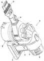
도 1은 본 발명의 제1 실시예에 따른 원심 분리 장치를 포함하는 핸드헬드 진공 청소기를 나타낸 도면이다.1 is a view showing a handheld vacuum cleaner including a centrifugal separator according to a first embodiment of the present invention.
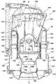
도 2는, 도 1의 핸드헬드 진공 청소기의 원심 분리 장치의 길이 방향의 축을 따른 단면도이다.FIG. 2 is a cross-sectional view along an axis in the longitudinal direction of the centrifugal separator of the handheld vacuum cleaner of FIG. 1.
도 3은, 도 1의 핸드헬드 진공 청소기의 원심 분리 장치의 측단면도이다.3 is a side cross-sectional view of the centrifugal separator of the handheld vacuum cleaner of FIG. 1.
도 4 내지 도 11은 본 발명의 실시예에 따른 원심 분리 장치 부분에 대한 다른 실시예를 나타낸 개략도이다.4 to 11 are schematic diagrams showing another embodiment of the centrifugal separator portion according to the embodiment of the present invention.
본 발명의 실시예에 대하여 첨부도면을 참조하여 설명한다.Embodiments of the present invention will be described with reference to the accompanying drawings.
도 1은 핸드헬드 진공 청소기(10)를 나타낸다. 핸드헬드 진공 청소기(10)는 모터 및 팬 유닛(도시하지 않음)을 수용하는 본체(12)를 가진다. 본체(12)는 또한 배터리와 같은 전원(power source)(14)을 포함한다. 본체(12)에는 핸드헬드 진공 청소기(10)를 사용 시에 조작하기 위한 핸들(handle)(16)이 제공되어 있다. 원심 분리 장치(100)는 본체(12)에 장착된다. 유입 파이프(inlet pipe)(18)는 본체(12)로부터 멀리 떨어진 원심 분리 장치(100)의 부분으로부터 연장되어 있다. 예를 들면, 더러운 공기 유입구(dirty air inlet)(20)는 유입 파이프(18)의 원단부(distal end)에 형성되어 있다. 브러시 도구(bruch tool)(22)는 유입 파이프(18)의 원단부에 슬라이딩 가능하게(slidably) 탑재되어 있다. 본체(12)에는 핸드헬드 진공 청소기(10)로부터 공기를 배출하기 위한 한 세트의 배출 벤트(exhaust vent)가 제공되어 있다.1 shows a
도 2 및 도 3에는 핸드헬드 진공 청소기(10)의 일부를 구성하는 원심 분리 장치(100)를 자세하게 나타낸다. 원심 분리 장치(100)는 길이 방향의 축(X-X) 및 벽(104)을 가지는 사이클론(102)을 포함한다. 벽(104)은 제1 부분(106)과 제2 부분(108)을 포함한다.2 and 3 show the
유입구(110)는 벽(104)에 형성되어 있고, 벽(104)의 제1 부분(106)이 유입구(110)와 벽(104)의 제2 부분(108) 사이에 위치되도록 배치되어 있다. 유입구(110)는 더러운 공기 유입구(20)와 연결되어 있고, 유입 파이프(18)와 사이클론(102)의 내부 사이에 연결 통로를 형성한다. 공기 유입구(110)는 사이클론(102)에 대하여 접선 방향(tangentially)에 배치되어 들어오는 공기가 사이클론(102)의 내부 둘레의 나선 통로를 따르게 한다.
벽(104)의 제1 부분(106)은 실질적으로 원통형이고 2개의 부분으로 되어 있다. 그래서 이 부분들은 사이클론(102)의 내부를 청소할 수 있도록 분리될 수 있 다. 그러나, 이것은 본 발명에 있어 필수적인 것은 아니다. 벽(104)의 제2 부분은 벽(104)의 제1 부분(106)보다 길이 방향의 축(X-X)으로부터 더 멀리 떨어져 있다. 벽(104)의 제2 부분(108)은 숄더(shoulder)(112) 및 원통부(cylindrical part)(113)을 포함한다. 립(114)은 벽(104)의 제1 부분(106)으로부터 사이클론(102)의 벽(104)의 제2 부분(108)으로 둘러싸인 공간으로 연장된다. 립(114)은 벽(104)의 제1 부분(106)의 실질적으로 일직선의 연장선을 형성한다. 립(114)의 기능은 후술한다.The
베이스(116)는 사이클론(102)의 일단을 폐쇄한다. 이 베이스(116)를 힌지(118)에 의하여 벽(104)의 제2 부분(108)의 하단에 선회 가능하게 탑재되어 있다. 베이스(116)는 고정쇠(catch)(120)에 의하여 (도 1 내지 도 3에 나타낸 바와 같이) 폐쇄 위치에 유지된다.
덮개(shroud)(121)는 사이클론(102)의 벽(104) 안쪽에 위치되어 있다. 덮개(121)는 복수의 관통 구멍(123)을 가지는 원통형 벽(122)을 포함한다. 덮개(121)는 사이클론(102)의 유출구(124)를 둘러싼다. 유출구(124)는 사이클론(102)과 추가 사이클론 어셈블리(126) 사이에 연결 통로를 제공한다. 립(128)은 공기는 통과시키고 쓰레기 및 먼지는 포획하도록 설계된 복수의 관통 구멍을 가진다.
추가 사이클론 어셈블리(126)는 병렬로 배치된 복수의 추가 사이클론(130)을 포함한다. 본 실시예에서는, 6개의 추가 사이클론(130)을 제공한다. 각각의 추가 사이클론(130)은 접선 방향으로 배치된 공기 유입구(132) 및 공기 유출구(134)를 가진다. 각각의 공기 유입구(132) 및 공기 유출구(134)는 각각의 추가 사이클론(130)의 제1 단부에 위치되어 있다. 원뿔형 개구부(cone opening)(136)는 각각의 추가 사이클론(130)의 제2 단부에 위치되어 있다. 각각의 추가 사이클론(130)의 원뿔형 개구부(136)는 도 3에서 가장 잘 볼 수 있는 바와 같이, 각각의 추가 사이클론(130)의 길이 방향의 축(도시하지 않음)에 대하여 경사져 있다. 각각의 추가 사이클론(130)의 원뿔형 개구부(136)는 덮개(121)의 안쪽에 위치된 벽(140)에 의해 정해지는 통로(138)와 연결되어 있다.The
집진기(142)는 통로(138)의 하단부에 위치되어 있다. 집진기(142)는 사다리꼴(frustoconical)의 제1 부분(144)과 원통형의 제2 부분(146)을 포함한다. 집진기(142)의 내부는 베이스(116)와 집진기(142)의 제1 부분(144) 및 제2 부분(146)의 측면으로 둘러싸여 있다.
추가 립(148)은 원통형의 제2 부분(146)으로 둘러싸인 집진기(142)의 부분 내로 연장된다. 이 추가 립(148)은 사디리꼴의 부분(148a)과 집진기(142)의 제2 부분(146)의 측면과 실질적으로 평행하게 연장되는 원통형의 부분(148b)을 포함한다. 추가 립(148)의 기능에 대해서는 후술한다.The
추가 사이클론(130)의 공기 유출구(134) 각각은 덕트(duct)(150)와 연결되어 있다. 덕트(150)는 원심 분리 장치(100)로부터 핸드헬드 진공 청소기(10)의 다른 부분으로의 기류 통로를 제공한다. 덕트(150)의 하류 단부에는 프리모터 필터(152)가 배치되어 있다. 프리모터 필터(152)는 발포체(form)와 같은 다공성 물질(porous material)을 포함한다.Each
사용 시에, 모터 및 팬 유닛은 쓰레기가 포함된 공기의 흐름을, 유입 파이프(18)를 통하여, 더러운 공기 유입구(20) 및 원심 분리 장치(100) 내로 빨아들인다. 쓰레기가 포함된 공기는 유입구(110)를 통하여 원심 분리 장치(100)로 들어간다. 접선 방향의 유입구(110)의 접선 구성(tangential arrangement)에 의해, 기류는 벽(104)의 내부 둘레의 나선 통로를 따라가게 된다. 큰 쓰레기 및 먼지 입자는 벽(104) 주위의 원심 운동에 의해 분리된다. 이 입자들은 그 후 사이클론(102)의 베이스(116)에 모인다. 큰 입자의 분리는 벽(104)의 제1 부분(106)으로 둘러싸인 사이클론(102)의 영역에서 일어날 것이고, 또한 립(114)으로 둘러싸인 사이클론(102)의 부분에서도 일어날 것이다. 분리된 입자는 벽(104)의 제2 부분(108)으로 둘러싸인 사이클론(102)의 부분에 모인다. 부분적으로 깨끗해진 기류는 그 후 사이클론(102)의 내부를 역류하여 덮개(121)의 관통 구멍을 통하여 사이클론(102)을 나간다. 일단 기류가 덮개(121)를 통과하면, 유출구(130)로 들어가고 그곳에서 각각의 추가 사이클론(130)의 접선 유입구(132) 사이에서 나뉜다. 그러므로, 추가 사이클론(130)은 사이클론(102)에서보다 더 작은 입자의 쓰레기 및 먼지를 부분적으로 깨끗해진 기류로부터 분리할 수 있다. 분리된 쓰레기 및 먼지는 원뿔형의 개구부(136)를 통하여 추가 사이클론(130)을 나간다. 그 후, 분리된 쓰레기 및 먼지는 통로(138)를 지나 집진기(142)로 들어간다. 결국 분리된 쓰레기 및 먼지는 집진기(142)의 베이스에 가라앉는다.In use, the motor and fan unit draws in a stream of air containing waste through the
그 후, 깨끗한 공기는 추가 사이클론(130)을 역류하여, 공기 유입구(134)를 통하여 추가 사이클론(130)을 나가 덕트(150)로 들어간다. 깨끗해진 공기는 덕 트(150)를 통과한 후, 프리모터 필터(152), 모터 및 팬 유닛, 그리고 포스트모터 필터를 차례로 지난 후, 공기 벤트(air vent)(24)를 통하여 핸드헬드 진공 청소기(10)로부터 배출된다.Clean air then flows back to the
사용 시에, 핸드헬드 진공 청소기(10)는 여러 방향으로 유지될 것이다. 사용 시에 핸드헬드 진공 청소기(10)는 거꾸로 될 수도 있다. 원심 분리 장치(100)가 수직에서 벗어나 기울어질 때, 다른 경우라면 유입구(110) 및 덮개(121) 쪽으로 이동하는 대부분의 분리된 쓰레기 및 먼지가, 립(114)과 벽(104)의 제2 부분(108) 사이의 환형의 포켓(annular pocket) 내에 걸린다. 또한, 전술한 포켓의 존재는 사이클론(102)의 하부(lower potion) 내에 정체 지점(stagnation point) 및 와류(eddy-current)의 형성을 도울 수 있다. 이것은 또한 분리된 쓰레기 및 먼지가 귀환 기류 중에 재비산하는 것을 막을 수 있다.In use, the
집진기(142)에 대해 설명하면, 포겟은 집진기(142)의 제2 부분(146)과 추가 립(148) 사이에 형성되어 있다. 이 포켓은 핸드헬드 진공 청소기(10)가 수직에서 벗어나 기울어질 때, 추가 사이클론(130)의 다른 부분 또는 원뿔형의 개구부(136)를 차단할 가능성이 있는 분리된 쓰레기 및 먼지의 일정 부분이 통로(138)에 재비산하는 것을 방지할 것이다.Referring to the
고정쇠(120)를 풀어 베이스(116)가 힌지(118)에 대하여 선회할 수 있게 함으로써 사이클론(102) 및 집진기(142)를 동시에 비울 수 있게 하여, 분리된 쓰레기 및 먼지를 원심 분리 장치(100)에서 버릴 수 있다.By loosening the
립(114) 및 추가 립(148)은 모두, 제1 실시예에 나타낸 것과는 상이한 구성 또는 형상을 취할 수 있다. 도 4 내지 도 11은 본 발명의 범위 내에 있는 립 또는 립들에 대한 8개의 다른 구성을 개략적으로 나타낸다. 이들 도면에서, 립과 접해 있는 벽 부분의 전반적인 형상을 제외한 다른 세부사항은 생략한다. 이러한 구성의 립은 사이클론의 립 또는 집진기의 추가 립에 적용될 수 있다.Both the
도 4는 본 발명의 제2 실시예를 나타낸다. 본 실시예에서, 원심 분리 장치(200)는 벽의 제1 부분(204)으로부터 벽의 제2 부분(206)으로 둘러싸인 영역 내로 연장되는 립(202)을 포함한다. 이 립(202)은 공기는 통과시키고 큰 입자의 쓰레기 및 먼지는 차단하는 복수의 관통 구멍을 가진다. 그 밖에, 립(202)은 전술한 립(114)과 동일하다.4 shows a second embodiment of the present invention. In the present embodiment, the
도 5는 본 발명의 제3 실시예를 나타낸다. 본 실시예에서, 원심 분리 장치(250)는 벽의 사다리꼴 형상의 제1 부분(254)으로부터 벽의 제2 부분(256)으로 둘러싸인 영역 내로 연장되는 립(252)을 포함한다. 벽의 제2 부분(254)은 일부분은 사다리꼴 형상이고 일부는 원통형이다.5 shows a third embodiment of the present invention. In this embodiment, the
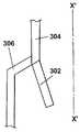
도 6은 본 발명의 제4 실시예를 나타낸다. 본 실시예에서(일정한 비례로 나타내지 않음), 원심 분리 장치(300)는 길이 방향의 축(X'-X')을 가지고, 벽의 원통 형상의 제1 부분(304)으로부터 벽의 제2 부분(306)으로 둘러싸인 영역 내로 연장되는 립(302)을 포함한다. 립(302)은 벽의 제1 부분(304)으로부터 길이 방향의 축(X'-X')에 대하여 비스듬히 안쪽으로 연장된다.6 shows a fourth embodiment of the present invention. In this embodiment (not shown to scale), the centrifugal separator 300 has a longitudinal axis X'-X 'and a second portion of the wall from the cylindrical
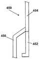
도 7은 본 발명의 제5 실시예를 나타낸다. 본 실시예에서(일정한 비례로 나타내지 않음), 원심 분리 장치(350)는 길이 방향의 축(X"-X")을 가지고, 벽의 원통 형상의 제1 부분(354)으로부터 벽의 제2 부분(356)으로 둘러싸인 영역 내로 연장되는 립(352)을 포함한다. 립(352)은 벽의 제1 부분(354)으로부터 길이 방향의 축(X"-X")에 대하여 비스듬히 바깥쪽으로 연장된다.7 shows a fifth embodiment of the present invention. In this embodiment (not shown to scale), the centrifugal separator 350 has a longitudinal axis X " -X " and a second portion of the wall from the cylindrical
도 8은 본 발명의 제6 실시예를 나타낸다. 본 실시예에서, 원심 분리 장치(400)는 벽의 원통 형상의 제1 부분(404)으로부터 벽의 제2 부분(406)으로 둘러싸인 영역 내로 연장되는 립(402)을 포함한다. 립(402)은 2개의 부분을 포함하는데, 제1 부분은 벽의 제1 부분(404)과 실질적으로 일직선의 연장선을 형성하고, 제2 부분은 제1 부분에 대하여 직각을 이루는 안쪽으로 연장되는 환형부를 형성한다.8 shows a sixth embodiment of the present invention. In this embodiment, the
도 9는 본 발명의 제7 실시예를 나타낸다. 본 실시예에서, 원심 분리 장치(450)는 립(452)과 벽의 제1 부분(454) 및 제2 부분(456)을 포함한다. 본 실시예는 환형부가 바깥쪽으로 연장되는 것을 제외하고는 제6 실시예와 동일하다.9 shows a seventh embodiment of the present invention. In this embodiment, the
도 10은 본 발명의 제6 실시예를 나타낸다. 본 실시예에서, 원심 분리 장치(500)는 벽의 원통 형상의 제1 부분(504)으로부터 벽의 제2 부분(506)으로 둘러싸인 영역 내로 연장되는 립(502)을 포함한다. 립(502)은 2개의 부분을 포함하는데, 제1 부분은 안쪽으로 연장되고, 제2 부분은 벽의 제1 부분(504)과 평행하게 연장된다.10 shows a sixth embodiment of the present invention. In this embodiment, the
도 11은 본 발명의 제9 실시예를 나타낸다. 본 실시예에서, 원심 분리 장치(550)는 원통형부와 환형부를 가지는 벽의 제1 부분(552)을 포함한다. 립(554)은 제1 부분(552)의 환형부로부터 벽의 제2 부분(556)으로 둘러싸인 영역 내로 연장된다.11 shows a ninth embodiment of the present invention. In this embodiment, the
도 4 내지 도 11에 나타낸 구성은 립 또는 립들의 구성, 형상, 및 수를 변경할 수 있다는 것을 보여주기 위한 것이다. 다른 구성도 역시 가능한 것은 물론이다. 예를 들면, 추가 사이클론 어셈블리는 임의의 개수의 사이클론을 포함할 수 있다. 다르게는, 추가 사이클론 어셈블리가 반드시 있어야 하는 것은 아니고, 필터 또는 기타 분리 수단으로 대체할 수 있다. 집진기나 집진기 상의 립은 반드시 있어야 하는 것은 아니다. 중요한 것은, 크기가 상이한 2개의 부분을 구비한 벽을 가지는 하나의 사이클론과, 작은 부분으로부터 큰 부분으로 연장되는 립이 존재한다는 것이다.4-11 is intended to show that the configuration, shape, and number of ribs or ribs can be changed. Of course, other configurations are also possible. For example, the additional cyclone assembly may comprise any number of cyclones. Alternatively, additional cyclone assemblies are not required and may be replaced by filters or other separation means. Dust collectors or ribs on the dust collector are not required. Importantly, there is one cyclone with a wall with two parts of different sizes and a lip extending from the small part to the large part.
전술한 실시예에서의 립은 모두 사이클론의 벽 주변의 둘레 전체로 연장된다. 그러나, 반드시 그럴 필요는 없다. 립은 사이클론의 벽 주변의 둘레 일부만으로 연장될 수도 있다. 다르게는, 복수의 립이 제공될 수 있으며, 각각의 립은 사이클론의 벽 주변의 둘레로 부분적으로 연장된다.The ribs in the above described embodiments all extend around the perimeter of the wall around the cyclone. However, it is not necessarily so. The lip may extend only a portion of the circumference around the wall of the cyclone. Alternatively, a plurality of ribs may be provided, with each lip partially extending around the wall periphery of the cyclone.
립은 사이클론의 벽의 제2 부분으로 둘러싸인 영역은 작은 일부분으로 연장될 수 있거나, 또는 립은 사이클론 내로 더욱 연장될 수 있다. 립은 임의의 수로 제공될 수 있으며, 예를 들면 수 개의 동심(concentric)의 립이 제공될 수 있다.The region surrounded by the second portion of the wall of the cyclone may extend into a small portion, or the lip may further extend into the cyclone. The ribs may be provided in any number, for example several concentric ribs may be provided.
Claims (17)
Translated fromKoreanApplications Claiming Priority (2)
| Application Number | Priority Date | Filing Date | Title |
|---|---|---|---|
| GB0614237.6 | 2006-07-18 | ||
| GB0614237AGB2440125A (en) | 2006-07-18 | 2006-07-18 | Cyclonic separating apparatus |
Publications (1)
| Publication Number | Publication Date |
|---|---|
| KR20090026209Atrue KR20090026209A (en) | 2009-03-11 |
Family
ID=36955841
Family Applications (4)
| Application Number | Title | Priority Date | Filing Date |
|---|---|---|---|
| KR1020097002164ACeasedKR20090034950A (en) | 2006-07-18 | 2007-07-06 | Handheld cleaner |
| KR1020097002167ACeasedKR20090026209A (en) | 2006-07-18 | 2007-07-06 | Centrifugal separator |
| KR1020097002161ACeasedKR20090026208A (en) | 2006-07-18 | 2007-07-06 | Handheld cleaning appliance |
| KR1020117018392AExpired - Fee RelatedKR101307568B1 (en) | 2006-07-18 | 2007-07-06 | Handheld cleaning appliance |
Family Applications Before (1)
| Application Number | Title | Priority Date | Filing Date |
|---|---|---|---|
| KR1020097002164ACeasedKR20090034950A (en) | 2006-07-18 | 2007-07-06 | Handheld cleaner |
Family Applications After (2)
| Application Number | Title | Priority Date | Filing Date |
|---|---|---|---|
| KR1020097002161ACeasedKR20090026208A (en) | 2006-07-18 | 2007-07-06 | Handheld cleaning appliance |
| KR1020117018392AExpired - Fee RelatedKR101307568B1 (en) | 2006-07-18 | 2007-07-06 | Handheld cleaning appliance |
Country Status (12)
| Country | Link |
|---|---|
| US (4) | US8156609B2 (en) |
| EP (3) | EP2043494B1 (en) |
| JP (3) | JP5158380B2 (en) |
| KR (4) | KR20090034950A (en) |
| CN (4) | CN101489460A (en) |
| AU (3) | AU2007274888B2 (en) |
| CA (2) | CA2658176C (en) |
| ES (1) | ES2397407T3 (en) |
| GB (3) | GB2440125A (en) |
| RU (2) | RU2437611C2 (en) |
| TW (3) | TW200901928A (en) |
| WO (1) | WO2008009884A1 (en) |
Cited By (6)
| Publication number | Priority date | Publication date | Assignee | Title |
|---|---|---|---|---|
| KR20140098847A (en)* | 2011-12-22 | 2014-08-08 | 다이슨 테크놀러지 리미티드 | Cyclonic separating apparatus |
| KR20140104012A (en)* | 2011-12-22 | 2014-08-27 | 다이슨 테크놀러지 리미티드 | Cyclonic separating apparatus |
| WO2019146923A1 (en) | 2018-01-29 | 2019-08-01 | 엘지전자 주식회사 | Cleaner |
| KR20210012691A (en) | 2019-07-26 | 2021-02-03 | 김경우 | A method for manufacturing a bread that is easy to insert filling and bread that is easy to insert filling using it |
| EP3984427A1 (en) | 2016-08-25 | 2022-04-20 | LG Electronics Inc. | Cyclonic vacuum cleaner |
| WO2024096455A1 (en)* | 2022-10-31 | 2024-05-10 | 엘지전자 주식회사 | Cleaner |
Families Citing this family (237)
| Publication number | Priority date | Publication date | Assignee | Title |
|---|---|---|---|---|
| GB2344606B (en) | 1998-12-07 | 2003-08-13 | Shell Int Research | Forming a wellbore casing by expansion of a tubular member |
| GB2440125A (en)* | 2006-07-18 | 2008-01-23 | Dyson Technology Ltd | Cyclonic separating apparatus |
| US9301666B2 (en) | 2006-12-12 | 2016-04-05 | Omachron Intellectual Property Inc. | Surface cleaning apparatus |
| US11666189B2 (en) | 2006-12-12 | 2023-06-06 | Omachron Intellectual Property Inc. | Surface cleaning apparatus with a variable inlet flow area |
| CA2599303A1 (en) | 2007-08-29 | 2009-02-28 | Gbd Corp. | Surface cleaning apparatus |
| US11819178B2 (en) | 2018-11-26 | 2023-11-21 | Omachron Intellectual Property Inc. | Surface cleaning apparatus |
| CA2593950C (en)* | 2006-12-12 | 2013-01-15 | G.B.D. Corp. | Surface cleaning apparatus |
| US8869344B2 (en) | 2006-12-12 | 2014-10-28 | G.B.D. Corp. | Surface cleaning apparatus with off-centre dirt bin inlet |
| US10765277B2 (en) | 2006-12-12 | 2020-09-08 | Omachron Intellectual Property Inc. | Configuration of a surface cleaning apparatus |
| US8950039B2 (en) | 2009-03-11 | 2015-02-10 | G.B.D. Corp. | Configuration of a surface cleaning apparatus |
| US8146201B2 (en) | 2006-12-12 | 2012-04-03 | G.B.D. Corp. | Surface cleaning apparatus |
| US12220099B2 (en) | 2006-12-12 | 2025-02-11 | Omachron Intellectual Property Inc. | Surface cleaning apparatus |
| US11793374B2 (en) | 2006-12-12 | 2023-10-24 | Omachron Intellectual Property Inc. | Surface cleaning apparatus with a variable inlet flow area |
| US11857142B2 (en) | 2006-12-15 | 2024-01-02 | Omachron Intellectual Property Inc. | Surface cleaning apparatus having an energy storage member and a charger for an energy storage member |
| US9192269B2 (en) | 2006-12-15 | 2015-11-24 | Omachron Intellectual Property Inc. | Surface cleaning apparatus |
| US10165912B2 (en) | 2006-12-15 | 2019-01-01 | Omachron Intellectual Property Inc. | Surface cleaning apparatus |
| US10258208B2 (en) | 2016-04-11 | 2019-04-16 | Omachron Intellectual Property Inc. | Surface cleaning apparatus |
| US20210401246A1 (en)* | 2016-04-11 | 2021-12-30 | Omachron Intellectual Property Inc. | Surface cleaning apparatus |
| US9888817B2 (en) | 2014-12-17 | 2018-02-13 | Omachron Intellectual Property Inc. | Surface cleaning apparatus |
| US12048409B2 (en) | 2007-03-11 | 2024-07-30 | Omachron Intellectual Property Inc. | Portable surface cleaning apparatus |
| US11751733B2 (en) | 2007-08-29 | 2023-09-12 | Omachron Intellectual Property Inc. | Portable surface cleaning apparatus |
| US12004700B2 (en) | 2007-08-29 | 2024-06-11 | Omachron Intellectual Property Inc. | Cyclonic surface cleaning apparatus |
| GB2453949B (en)* | 2007-10-23 | 2012-03-28 | Hoover Ltd | Cyclonic separation apparatus |
| GB2454227B (en) | 2007-11-01 | 2012-02-29 | Dyson Technology Ltd | Cyclonic separating apparatus |
| KR101472776B1 (en)* | 2007-11-05 | 2014-12-17 | 삼성전자주식회사 | Multi-cyclone dust collector of vacuum cleaner |
| KR100941429B1 (en)* | 2008-02-19 | 2010-02-11 | 엘지전자 주식회사 | Vacuum cleaner |
| USD595463S1 (en) | 2008-11-18 | 2009-06-30 | Black & Decker Inc. | Cordless hand-held vacuum |
| US8152602B2 (en)* | 2009-01-30 | 2012-04-10 | JPL Global, LLC | Grinder and core drill with dust collection |
| US20100192314A1 (en)* | 2009-02-03 | 2010-08-05 | Makita Corporation | Handy cleaners |
| CA2658006A1 (en)* | 2009-03-11 | 2010-09-11 | G.B.D. Corp. | Cyclonic surface cleaning apparatus |
| US9591952B2 (en) | 2009-03-11 | 2017-03-14 | Omachron Intellectual Property Inc. | Hand vacuum cleaner with removable dirt chamber |
| CA2658046A1 (en)* | 2009-03-11 | 2010-09-11 | G.B.D. Corp. | Surface cleaning apparatus |
| CA2658159A1 (en)* | 2009-03-13 | 2010-09-13 | G.B.D. Corp. | Dirt collection chamber for a cyclonic surface cleaning apparatus |
| CA2967272C (en) | 2009-03-13 | 2018-01-02 | Omachron Intellectual Property Inc. | Hand vacuum cleaner |
| US9433332B2 (en) | 2013-02-27 | 2016-09-06 | Omachron Intellectual Property Inc. | Surface cleaning apparatus |
| US12156626B2 (en) | 2009-03-13 | 2024-12-03 | Omachron Intellectual Property Inc. | Surface cleaning apparatus |
| US11690489B2 (en) | 2009-03-13 | 2023-07-04 | Omachron Intellectual Property Inc. | Surface cleaning apparatus with an external dirt chamber |
| US10722086B2 (en) | 2017-07-06 | 2020-07-28 | Omachron Intellectual Property Inc. | Handheld surface cleaning apparatus |
| US9265395B2 (en) | 2010-03-12 | 2016-02-23 | Omachron Intellectual Property Inc. | Surface cleaning apparatus |
| JP2010268876A (en)* | 2009-05-20 | 2010-12-02 | Panasonic Corp | Dust collector and vacuum cleaner |
| US9475180B2 (en) | 2010-01-07 | 2016-10-25 | Black & Decker Inc. | Power tool having rotary input control |
| US8418778B2 (en) | 2010-01-07 | 2013-04-16 | Black & Decker Inc. | Power screwdriver having rotary input control |
| US9266178B2 (en) | 2010-01-07 | 2016-02-23 | Black & Decker Inc. | Power tool having rotary input control |
| JP2011161003A (en)* | 2010-02-10 | 2011-08-25 | Panasonic Corp | Vacuum cleaner |
| CN101985299B (en)* | 2010-09-14 | 2012-08-29 | 浙江天鸿汽车用品有限公司 | Chargeable dust-collecting handheld dust removal system |
| GB2484146B (en)* | 2010-10-01 | 2013-02-13 | Dyson Technology Ltd | A vacuum cleaner |
| DE112012000251B4 (en)* | 2011-02-18 | 2018-04-12 | Techtronic Floor Care Technology Ltd. | Dust container for vacuum cleaners |
| KR101526293B1 (en)* | 2011-04-15 | 2015-06-05 | 다이슨 테크놀러지 리미티드 | Cyclonic separator with shroud comprising an inlet opening and exit perforations |
| JP5770029B2 (en)* | 2011-06-24 | 2015-08-26 | 株式会社東芝 | Electric vacuum cleaner |
| EP2581013B1 (en)* | 2011-10-12 | 2016-11-23 | Black & Decker Inc. | Hand-holdable vacuum cleaner with cyclonic separation apparatus |
| KR200469728Y1 (en)* | 2011-12-26 | 2013-11-05 | 대우조선해양 주식회사 | cyclone dust collector |
| EP2631035B1 (en) | 2012-02-24 | 2019-10-16 | Black & Decker Inc. | Power tool |
| GB2508035B (en)* | 2012-11-20 | 2015-03-11 | Dyson Technology Ltd | Cleaning appliance |
| US9027198B2 (en) | 2013-02-27 | 2015-05-12 | G.B.D. Corp. | Surface cleaning apparatus |
| US9591958B2 (en) | 2013-02-27 | 2017-03-14 | Omachron Intellectual Property Inc. | Surface cleaning apparatus |
| US9320401B2 (en)* | 2013-02-27 | 2016-04-26 | Omachron Intellectual Property Inc. | Surface cleaning apparatus |
| US10729294B2 (en) | 2013-02-28 | 2020-08-04 | Omachron Intellectual Property Inc. | Hand carryable surface cleaning apparatus |
| US20140237764A1 (en) | 2013-02-28 | 2014-08-28 | G.B.D. Corp. | Cyclone such as for use in a surface cleaning apparatus |
| US10674884B2 (en) | 2013-02-28 | 2020-06-09 | Omachron Intellectual Property Inc. | Hand carryable surface cleaning apparatus |
| US9775484B2 (en) | 2013-03-01 | 2017-10-03 | Omachron Intellectual Property Inc. | Surface cleaning apparatus |
| CN103690104B (en)* | 2013-10-31 | 2016-02-03 | 苏州邦威电器有限公司 | A kind of many dust separation structure type dust barrel |
| USD742081S1 (en) | 2014-01-15 | 2015-10-27 | Milwaukee Electric Tool Corporation | Dust collector |
| USD741557S1 (en) | 2014-01-15 | 2015-10-20 | Milwaukee Electric Tool Corporation | Dust collector |
| CN103784081B (en)* | 2014-01-27 | 2017-02-08 | 科沃斯机器人股份有限公司 | Handheld dust collector |
| WO2015123538A1 (en) | 2014-02-14 | 2015-08-20 | Techtronic Industries Co. Ltd. | Vacuum cleaner with a separator received within the dirt collection chamber |
| CA158205S (en)* | 2014-02-21 | 2015-03-04 | Dyson Technology Ltd | Filter casing for a vacuum cleaner |
| AU357474S (en)* | 2014-02-21 | 2014-09-18 | Dyson Technology Ltd | Vacuum cleaner |
| AU357472S (en)* | 2014-02-21 | 2014-09-18 | Dyson Technology Ltd | Vacuum cleaner |
| AU357468S (en)* | 2014-02-21 | 2014-09-18 | Dyson Technology Ltd | Vacuum cleaner |
| CA158204S (en)* | 2014-02-21 | 2015-03-04 | Dyson Technology Ltd | Filter casing for a vacuum cleaner |
| AU357471S (en)* | 2014-02-21 | 2014-09-18 | Dyson Technology Ltd | Vacuum cleaner |
| EP3125736B1 (en) | 2014-04-04 | 2018-06-13 | Techtronic Industries Company Limited | Vaccum cleaner |
| US9451853B2 (en) | 2014-07-18 | 2016-09-27 | Omachron Intellectual Property Inc. | Portable surface cleaning apparatus |
| US11707173B2 (en) | 2014-07-18 | 2023-07-25 | Omachron Intellectual Property Inc. | Surface cleaning apparatus |
| US10791889B2 (en) | 2016-01-08 | 2020-10-06 | Omachron Intellectual Property Inc. | Hand carryable surface cleaning apparatus |
| US9585530B2 (en) | 2014-07-18 | 2017-03-07 | Omachron Intellectual Property Inc. | Portable surface cleaning apparatus |
| US9314139B2 (en) | 2014-07-18 | 2016-04-19 | Omachron Intellectual Property Inc. | Portable surface cleaning apparatus |
| US9420925B2 (en) | 2014-07-18 | 2016-08-23 | Omachron Intellectual Property Inc. | Portable surface cleaning apparatus |
| KR102246450B1 (en)* | 2014-10-15 | 2021-04-30 | 삼성전자주식회사 | Cleaner |
| EP3209175B1 (en) | 2014-10-22 | 2023-01-04 | Techtronic Industries Co. Ltd. | Handheld vacuum cleaner |
| US9693665B2 (en) | 2014-10-22 | 2017-07-04 | Techtronic Industries Co. Ltd. | Vacuum cleaner having cyclonic separator |
| WO2016065146A1 (en) | 2014-10-22 | 2016-04-28 | Techtronic Industries Co. Ltd. | Vacuum cleaner having cyclonic separator |
| US10022027B2 (en) | 2014-12-17 | 2018-07-17 | Omachron Intellectual Property Inc. | All in the head surface cleaning apparatus |
| US11445873B2 (en) | 2014-12-17 | 2022-09-20 | Omachron Intellectual Property Inc. | Hand carryable surface cleaning apparatus |
| US9883781B2 (en) | 2014-12-17 | 2018-02-06 | Omachron Intellectual Property Inc. | All in the head surface cleaning apparatus |
| US10251519B2 (en) | 2014-12-17 | 2019-04-09 | Omachron Intellectual Property Inc. | Surface cleaning apparatus |
| US11445871B2 (en) | 2014-12-17 | 2022-09-20 | Omachron Intellectual Property Inc. | Surface cleaning apparatus |
| US10136778B2 (en) | 2014-12-17 | 2018-11-27 | Omachron Intellectual Property Inc. | Surface cleaning apparatus |
| US11950745B2 (en) | 2014-12-17 | 2024-04-09 | Omachron Intellectual Property Inc. | Surface cleaning apparatus |
| US11445874B2 (en) | 2014-12-17 | 2022-09-20 | Omachron Intellectual Property Inc. | Hand carryable surface cleaning apparatus |
| KR101653481B1 (en) | 2015-01-16 | 2016-09-01 | 엘지전자 주식회사 | Vacuum cleaner and dust collecting apparatus |
| EP3264959B1 (en)* | 2015-03-06 | 2019-05-29 | Alfred Kärcher SE & Co. KG | Vacuum cleaner |
| JP2017055835A (en)* | 2015-09-14 | 2017-03-23 | 東芝ライフスタイル株式会社 | Vacuum cleaner |
| GB2542388B (en)* | 2015-09-17 | 2018-04-04 | Dyson Technology Ltd | Vacuum cleaner |
| GB2542385B (en) | 2015-09-17 | 2018-10-10 | Dyson Technology Ltd | Vacuum Cleaner |
| GB2542387B (en) | 2015-09-17 | 2017-11-01 | Dyson Technology Ltd | Vacuum cleaner |
| GB2542386B (en) | 2015-09-17 | 2018-10-10 | Dyson Technology Ltd | Vacuum Cleaner |
| US10080471B2 (en) | 2015-12-21 | 2018-09-25 | Electrolux Home Care Products, Inc. | Versatile vacuum cleaners |
| US12390062B2 (en) | 2016-01-08 | 2025-08-19 | Omachron Intellectual Property Inc. | Hand carryable surface cleaning apparatus |
| WO2017117679A1 (en) | 2016-01-08 | 2017-07-13 | Omachron Intellectual Property Inc. | Hand carryable surface cleaning apparatus |
| US10165914B2 (en) | 2016-01-08 | 2019-01-01 | Omachron Intellectual Property Inc. | Hand carryable surface cleaning apparatus |
| CN105496302A (en)* | 2016-01-08 | 2016-04-20 | 宁波春仁电器有限公司 | Hand-held cleaner |
| CN105496301B (en)* | 2016-01-08 | 2018-12-28 | 宁波春仁电器有限公司 | A kind of hand held cleaner |
| US11839343B2 (en) | 2019-08-15 | 2023-12-12 | Omachron Intellectual Property Inc. | Handheld surface cleaning apparatus |
| US9980616B2 (en) | 2016-01-08 | 2018-05-29 | Omachron Intellectual Property Inc. | Hand carryable surface cleaning apparatus |
| US9962048B2 (en) | 2016-01-08 | 2018-05-08 | Omachron Intellectual Property | Hand carryable surface cleaning apparatus |
| EP3238589B1 (en) | 2016-01-20 | 2019-05-29 | Jiangsu Midea Cleaning Appliances Co., Ltd. | Hand-held vacuum cleaner |
| CN106073629B (en)* | 2016-01-20 | 2019-05-10 | 江苏美的清洁电器股份有限公司 | Hand held cleaner |
| CN105662273B (en)* | 2016-01-20 | 2019-03-29 | 江苏美的清洁电器股份有限公司 | Hand held cleaner |
| EP3238588A4 (en) | 2016-01-20 | 2018-05-30 | Jiangsu Midea Cleaning Appliances Co., Ltd. | Vacuum cleaner |
| WO2017124627A1 (en)* | 2016-01-20 | 2017-07-27 | 江苏美的清洁电器股份有限公司 | Vacuum cleaner |
| CA2971142A1 (en) | 2016-01-20 | 2017-07-27 | Jiangsu Midea Cleaning Appliances Co., Ltd. | Hand-held vacuum cleaner |
| GB2546542B (en)* | 2016-01-22 | 2018-07-04 | Dyson Technology Ltd | Vacuum cleaner |
| GB2546541B (en)* | 2016-01-22 | 2018-07-04 | Dyson Technology Ltd | Vacuum cleaning apparatus |
| WO2017171496A1 (en) | 2016-03-31 | 2017-10-05 | 엘지전자 주식회사 | Cleaning apparatus |
| EP4104733B1 (en) | 2016-03-31 | 2023-08-30 | LG Electronics Inc. | Cleaning apparatus |
| US11166607B2 (en) | 2016-03-31 | 2021-11-09 | Lg Electronics Inc. | Cleaner |
| KR102560970B1 (en) | 2016-03-31 | 2023-07-31 | 엘지전자 주식회사 | Cleaner |
| DE112017001802T5 (en) | 2016-03-31 | 2019-01-03 | Lg Electronics Inc. | cleaning device |
| US9986880B2 (en) | 2016-04-11 | 2018-06-05 | Omachron Intellectual Property Inc. | Surface cleaning apparatus |
| US10016105B2 (en) | 2016-04-11 | 2018-07-10 | Omachron Intellectual Property Inc. | Surface cleaning apparatus |
| US10016104B2 (en) | 2016-04-11 | 2018-07-10 | Omachron Intellectual Property Inc. | Surface cleaning apparatus |
| US10568477B2 (en) | 2016-04-11 | 2020-02-25 | Omachron Intellectual Property Inc. | Surface cleaning apparatus |
| US11241129B2 (en) | 2016-04-11 | 2022-02-08 | Omachron Intellectual Property Inc. | Surface cleaning apparatus |
| US11918170B2 (en) | 2016-04-11 | 2024-03-05 | Omachron Intellectual Property Inc. | Surface cleaning apparatus |
| US10258210B2 (en) | 2016-12-27 | 2019-04-16 | Omachron Intellectual Property Inc. | Multistage cyclone and surface cleaning apparatus having same |
| USD811031S1 (en)* | 2016-06-01 | 2018-02-20 | Sharkninja Operating Llc | Filter cap for a handheld vacuum |
| USD813475S1 (en)* | 2016-06-01 | 2018-03-20 | Milwaukee Electric Tool Corporation | Handheld vacuum cleaner |
| WO2018011977A1 (en)* | 2016-07-15 | 2018-01-18 | 三菱電機株式会社 | Vacuum cleaner and hand dryer |
| USD821044S1 (en)* | 2016-08-05 | 2018-06-19 | Jiangsu Midea Cleaning Appliances Co., Ltd. | Vacuum cleaner |
| TWI749018B (en) | 2016-08-25 | 2021-12-11 | 南韓商Lg電子股份有限公司 | Cleaner |
| WO2018038365A1 (en) | 2016-08-25 | 2018-03-01 | 엘지전자 주식회사 | Vacuum |
| WO2018038372A1 (en)* | 2016-08-25 | 2018-03-01 | 엘지전자 주식회사 | Vacuum |
| WO2018038473A1 (en)* | 2016-08-25 | 2018-03-01 | 엘지전자 주식회사 | Vacuum |
| EP3329821A1 (en)* | 2016-12-03 | 2018-06-06 | Koninklijke Philips N.V. | Vacuum cleaner |
| US11285495B2 (en) | 2016-12-27 | 2022-03-29 | Omachron Intellectual Property Inc. | Multistage cyclone and surface cleaning apparatus having same |
| US10827891B2 (en) | 2016-12-27 | 2020-11-10 | Omachron Intellectual Property Inc. | Multistage cyclone and surface cleaning apparatus having same |
| US10271704B2 (en) | 2016-12-27 | 2019-04-30 | Omachron Intellectual Property Inc. | Multistage cyclone and surface cleaning apparatus having same |
| US10299643B2 (en) | 2016-12-27 | 2019-05-28 | Omachron Intellectual Property Inc. | Multistage cyclone and surface cleaning apparatus having same |
| US10405709B2 (en) | 2016-12-27 | 2019-09-10 | Omachron Intellectual Property Inc. | Multistage cyclone and surface cleaning apparatus having same |
| US10016106B1 (en) | 2016-12-27 | 2018-07-10 | Omachron Intellectual Property Inc. | Multistage cyclone and surface cleaning apparatus having same |
| US10464746B2 (en) | 2016-12-28 | 2019-11-05 | Omachron Intellectual Property Inc. | Dust and allergen control for surface cleaning apparatus |
| US10214349B2 (en) | 2016-12-28 | 2019-02-26 | Omachron Intellectual Property Inc. | Dust and allergen control for surface cleaning apparatus |
| US10244910B2 (en) | 2016-12-28 | 2019-04-02 | Omachron Intellectual Property Inc. | Dust and allergen control for surface cleaning apparatus |
| US10244909B2 (en) | 2016-12-28 | 2019-04-02 | Omachron Intellectual Property Inc. | Dust and allergen control for surface cleaning apparatus |
| US10322873B2 (en) | 2016-12-28 | 2019-06-18 | Omachron Intellectual Property Inc. | Dust and allergen control for surface cleaning apparatus |
| AU201715439S (en)* | 2017-03-16 | 2017-10-10 | Dyson Technology Ltd | Vacuum cleaner |
| AU201715412S (en) | 2017-03-16 | 2017-10-09 | Dyson Technology Ltd | Vacuum cleaner |
| AU201715425S (en)* | 2017-03-16 | 2017-10-09 | Dyson Technology Ltd | Vacuum cleaner |
| AU201715444S (en) | 2017-03-16 | 2017-10-10 | Dyson Technology Ltd | Vacuum cleaner |
| USD851343S1 (en)* | 2017-03-16 | 2019-06-11 | Dyson Technology Limited | Part of a vacuum cleaner |
| AU201715432S (en)* | 2017-03-16 | 2017-10-10 | Dyson Technology Ltd | Vacuum cleaner |
| AU201715474S (en) | 2017-03-16 | 2017-10-09 | Dyson Technology Ltd | Vacuum cleaner |
| AU201715476S (en)* | 2017-03-16 | 2017-10-09 | Dyson Technology Ltd | Vacuum cleaner |
| AU201715409S (en)* | 2017-03-16 | 2017-10-04 | Dyson Technology Ltd | Vacuum cleaner |
| CN107007210B (en)* | 2017-05-26 | 2022-08-19 | 小狗电器互联网科技(北京)股份有限公司 | Vacuum cleaner |
| DE102017209158A1 (en) | 2017-05-31 | 2018-12-06 | BSH Hausgeräte GmbH | Easily emptied hand-held battery-operated vacuum cleaner |
| GB2598506B (en) | 2017-06-19 | 2022-06-08 | Techtronic Floor Care Tech Ltd | A dirt separation device |
| EP3641610B1 (en)* | 2017-06-19 | 2023-03-15 | Techtronic Floor Care Technology Limited | Cyclonic separator device |
| US10702113B2 (en) | 2017-07-06 | 2020-07-07 | Omachron Intellectual Property Inc. | Handheld surface cleaning apparatus |
| US10966583B2 (en) | 2019-01-23 | 2021-04-06 | Omachron Intellectual Property Inc. | Surface cleaning apparatus, cyclonic air treatment member and surface cleaning apparatus including the same |
| US10750913B2 (en) | 2017-07-06 | 2020-08-25 | Omachron Intellectual Property Inc. | Handheld surface cleaning apparatus |
| US10828649B2 (en) | 2019-01-23 | 2020-11-10 | Omachron Intellectual Property Inc. | Cyclonic air treatment member and surface cleaning apparatus including the same |
| US10537216B2 (en) | 2017-07-06 | 2020-01-21 | Omachron Intellectual Property Inc. | Handheld surface cleaning apparatus |
| US11666193B2 (en) | 2020-03-18 | 2023-06-06 | Omachron Intellectual Property Inc. | Surface cleaning apparatus with removable air treatment member assembly |
| US11219906B2 (en) | 2019-01-23 | 2022-01-11 | Omachron Intellectual Property Inc. | Surface cleaning apparatus, cyclonic air treatment member and surface cleaning apparatus including the same |
| US10842330B2 (en) | 2017-07-06 | 2020-11-24 | Omachron Intellectual Property Inc. | Handheld surface cleaning apparatus |
| US11745190B2 (en) | 2019-01-23 | 2023-09-05 | Omachron Intellectual Property Inc. | Surface cleaning apparatus |
| US10631693B2 (en) | 2017-07-06 | 2020-04-28 | Omachron Intellectual Property Inc. | Handheld surface cleaning apparatus |
| US10506904B2 (en) | 2017-07-06 | 2019-12-17 | Omachron Intellectual Property Inc. | Handheld surface cleaning apparatus |
| US11730327B2 (en) | 2020-03-18 | 2023-08-22 | Omachron Intellectual Property Inc. | Surface cleaning apparatus with removable air treatment assembly |
| US11445878B2 (en) | 2020-03-18 | 2022-09-20 | Omachron Intellectual Property Inc. | Surface cleaning apparatus with removable air treatment member assembly |
| US11766156B2 (en) | 2020-03-18 | 2023-09-26 | Omachron Intellectual Property Inc. | Surface cleaning apparatus with removable air treatment member assembly |
| JP6811692B2 (en)* | 2017-08-08 | 2021-01-13 | 日立グローバルライフソリューションズ株式会社 | Vacuum cleaner |
| US10575701B2 (en) | 2017-09-15 | 2020-03-03 | Omachron Intellectual Property Inc. | Surface cleaning apparatus |
| USD869802S1 (en) | 2017-09-15 | 2019-12-10 | Dyson Technology Limited | Part of a vacuum cleaner |
| EP3684237B1 (en) | 2017-09-22 | 2023-07-19 | SharkNinja Operating LLC | Hand-held surface cleaning device |
| US10575693B2 (en)* | 2018-01-02 | 2020-03-03 | Omachron Intellectual Property Inc. | Surface cleaning apparatus |
| US11478116B2 (en) | 2018-01-15 | 2022-10-25 | Omachron Intellectual Property Inc | Surface cleaning apparatus |
| US11930987B2 (en)* | 2018-04-20 | 2024-03-19 | Omachron Intellectual Property Inc. | Surface cleaning apparatus |
| KR102074288B1 (en)* | 2018-05-31 | 2020-02-06 | 엘지전자 주식회사 | Cleaning Appliance |
| KR102073618B1 (en)* | 2018-05-31 | 2020-02-05 | 엘지전자 주식회사 | Cleaning Appliance |
| US20190373822A1 (en)* | 2018-06-12 | 2019-12-12 | Ned A Hamad, JR. | Collapsible Mulch Dispenser |
| CN108852171B (en)* | 2018-07-23 | 2023-09-15 | 北京石头世纪科技股份有限公司 | Handheld cleaning equipment |
| US11006799B2 (en) | 2018-08-13 | 2021-05-18 | Omachron Intellectual Property Inc. | Cyclonic air treatment member and surface cleaning apparatus including the same |
| US11013384B2 (en) | 2018-08-13 | 2021-05-25 | Omachron Intellectual Property Inc. | Cyclonic air treatment member and surface cleaning apparatus including the same |
| US11192122B2 (en) | 2018-08-13 | 2021-12-07 | Omachron Intellectual Property Inc. | Cyclonic air treatment member and surface cleaning apparatus including the same |
| US10882059B2 (en) | 2018-09-21 | 2021-01-05 | Omachron Intellectual Property Inc. | Multi cyclone array for surface cleaning apparatus and a surface cleaning apparatus having same |
| WO2020055215A1 (en) | 2018-09-14 | 2020-03-19 | 엘지전자 주식회사 | Cleaner |
| EP3851009B1 (en) | 2018-09-14 | 2025-06-18 | LG Electronics Inc. | Vacuum cleaner |
| AU2019339245B2 (en) | 2018-09-14 | 2022-08-11 | Lg Electronics Inc. | Cleaner |
| US10974258B2 (en) | 2019-01-23 | 2021-04-13 | Omachron Intellectual Property Inc. | Surface cleaning apparatus, cyclonic air treatment member and surface cleaning apparatus including the same |
| US11026550B2 (en) | 2019-01-23 | 2021-06-08 | Omachron Intellectual Property Inc. | Surface cleaning apparatus, cyclonic air treatment member and surface cleaning apparatus including the same |
| US11135602B2 (en) | 2019-01-23 | 2021-10-05 | Omachron Intellectual Property Inc. | Surface cleaning apparatus, cyclonic air treatment member and surface cleaning apparatus including the same |
| GB2612750B (en)* | 2019-01-23 | 2023-09-27 | Omachron Intellectual Property Inc | Surface cleaning apparatus, cyclonic air treatment member and surface cleaning apparatus including the same |
| US11059054B2 (en) | 2019-01-23 | 2021-07-13 | Omachron Intellectual Property Inc. | Surface cleaning apparatus, cyclonic air treatment member and surface cleaning apparatus including the same |
| US11213832B2 (en) | 2019-01-23 | 2022-01-04 | Omachron Intellectual Property Inc. | Surface cleaning apparatus, cyclonic air treatment member and surface cleaning apparatus including the same |
| US10925451B2 (en) | 2019-01-23 | 2021-02-23 | Omachron Intellectual Property Inc. | Surface cleaning apparatus, cyclonic air treatment member and surface cleaning apparatus including the same |
| US11129510B2 (en) | 2019-01-23 | 2021-09-28 | Omachron Intellectual Property Inc. | Surface cleaning apparatus, cyclonic air treatment member and surface cleaning apparatus including the same |
| US10919051B2 (en) | 2019-01-23 | 2021-02-16 | Omachron Intellectual Property Inc. | Surface cleaning apparatus, cyclonic air treatment member and surface cleaning apparatus including the same |
| WO2020186342A1 (en) | 2019-03-15 | 2020-09-24 | Omachron Intellectual Property Inc. | Surface cleaning apparatus |
| WO2020223619A1 (en) | 2019-05-01 | 2020-11-05 | Sharkninja Operating Llc | Vacuum cleaner and docking station for use with the same |
| JP7237767B2 (en)* | 2019-07-26 | 2023-03-13 | 日立グローバルライフソリューションズ株式会社 | vacuum cleaner |
| EP4501195A3 (en)* | 2019-08-15 | 2025-04-09 | Omachron Intellectual Property Inc. | Handheld surface cleaning apparatus |
| US11224324B2 (en) | 2019-08-15 | 2022-01-18 | Omachron Intellectual Property Inc. | Handheld surface cleaning apparatus |
| US11751740B2 (en) | 2019-11-18 | 2023-09-12 | Omachron Intellectual Property Inc. | Multi-inlet cyclone |
| US11246462B2 (en) | 2019-11-18 | 2022-02-15 | Omachron Intellectual Property Inc. | Multi-inlet cyclone |
| USD943228S1 (en)* | 2020-01-17 | 2022-02-08 | Suzhou Pooda Clean Technology Co., Ltd. | Vacuum cleaner |
| USD954371S1 (en)* | 2020-01-24 | 2022-06-07 | Dongguan Fornice Intelligent Technology Co., Ltd. | Hand-held vacuum cleaner |
| AU2021237991B2 (en)* | 2020-03-18 | 2024-08-01 | Omachron Intellectual Property Inc. | Surface cleaning apparatus with removable air treatment member assembly |
| KR20210144553A (en) | 2020-05-22 | 2021-11-30 | 엘지전자 주식회사 | Cleaner |
| US20230210331A1 (en) | 2020-05-22 | 2023-07-06 | Lg Electronics Inc. | Cleaner |
| AU2021274514B2 (en) | 2020-05-22 | 2024-06-27 | Lg Electronics Inc. | Vacuum cleaner |
| USD936311S1 (en)* | 2020-07-15 | 2021-11-16 | Suzhou Aza Clean Electric Technology Co., Ltd. | Vacuum cleaner |
| CN111904329B (en)* | 2020-08-12 | 2022-04-12 | 安慕科技(深圳)有限公司 | Hand-held dust collector with multiple groups of batteries |
| WO2022078177A1 (en)* | 2020-10-12 | 2022-04-21 | 北京石头世纪科技股份有限公司 | Cleaning apparatus |
| CN112716355B (en)* | 2020-12-24 | 2022-04-22 | 北京小狗吸尘器集团股份有限公司 | Cleaning tool with separating component |
| US11607096B2 (en) | 2021-02-03 | 2023-03-21 | Black & Decker, Inc. | Vacuum cleaner |
| EP4129138B1 (en)* | 2021-06-17 | 2024-08-28 | Shenzhen Shermon Technology Co., Limited | Separation structure of dust cup of dust collector |
| CA3182043A1 (en)* | 2021-11-17 | 2023-05-17 | Bissell Inc. | Handheld extraction cleaner |
| USD1041110S1 (en)* | 2022-05-06 | 2024-09-03 | Lg Electronics Inc. | Air outlet for vacuum cleaner |
| GB2635620A (en) | 2022-06-17 | 2025-05-21 | Origyn LLC | Waste receptacle and vacuum cleaner |
| CN115120134B (en)* | 2022-08-04 | 2024-05-31 | 北京顺造科技有限公司 | Cyclone separators and surface cleaning devices |
| EP4586870A1 (en) | 2022-09-15 | 2025-07-23 | SharkNinja Operating LLC | Vacuum cleaner and docking station configured to cooperate with the same |
| USD1054131S1 (en)* | 2022-09-16 | 2024-12-10 | Lg Electronics Inc. | Vacuum cleaner body |
| USD1047321S1 (en)* | 2022-09-30 | 2024-10-15 | Guangdong Well Technology Co., Ltd | Hand-held vacuum cleaner |
| USD991601S1 (en)* | 2023-01-12 | 2023-07-04 | Xun Lei | Vacuum cleaner |
| US20250213029A1 (en) | 2023-01-19 | 2025-07-03 | Sharkninja Operating Llc | Hair care appliance with powered attachment |
| US20240245190A1 (en) | 2023-01-19 | 2024-07-25 | Sharkninja Operating Llc | Identification of hair care appliance attachments |
| USD1077385S1 (en)* | 2023-08-21 | 2025-05-27 | Shenzhen Tecno Technology Co., Ltd | Vacuum cleaner body |
| USD1041102S1 (en)* | 2023-08-22 | 2024-09-03 | Ningbo Shanen Electric Appliance Co., Ltd. | Vacuum cleaner |
| USD1093781S1 (en)* | 2023-09-27 | 2025-09-16 | Zhejiang Prulde Electric Appliance Co., Ltd. | Vacuum cleaner |
| USD1051528S1 (en)* | 2023-10-16 | 2024-11-12 | Xiao Zhu | Car vacuum cleaner |
| USD1096028S1 (en)* | 2023-11-01 | 2025-09-30 | Suzhou Royal Cleanland Electric Co., Ltd. | Vacuum cleaner main unit |
| USD1091989S1 (en)* | 2023-12-12 | 2025-09-02 | Shenzhen Zhike Technology Co., Ltd | Vacuum cleaner grip |
| USD1093783S1 (en)* | 2024-02-08 | 2025-09-16 | Suzhou Aza Clean Electric Technology Co., Ltd. | Vacuum cleaner |
| CN118402723B (en)* | 2024-06-28 | 2024-11-05 | 追觅创新科技(苏州)有限公司 | Vacuum cleaning equipment and vacuum cleaning systems |
Family Cites Families (76)
| Publication number | Priority date | Publication date | Assignee | Title |
|---|---|---|---|---|
| US2399509A (en)* | 1941-09-09 | 1946-04-30 | Western Precipitation Corp | Multistage centrifugal separating apparatus |
| FR1554851A (en) | 1967-12-08 | 1969-01-24 | ||
| GB1261906A (en)* | 1968-07-05 | 1972-01-26 | Clarke Chapman John Thompson L | Cyclonic fluid separators |
| GB2035787B (en)* | 1978-11-11 | 1982-10-13 | L & H Designs Ltd & Merritt H | Suction cleaning device |
| SU1346496A1 (en)* | 1985-12-10 | 1987-10-23 | И.М. Ковалев и В.П. Новгородов | Container for stack of articles with recesses |
| GB9503334D0 (en)* | 1995-02-21 | 1995-04-12 | Black & Decker Inc | A cyclone dust extractor |
| US5692262A (en)* | 1996-01-22 | 1997-12-02 | Haupt; David J. | Mulching impeller for lawn and garden mulching blower-vacuum |
| GB2330786B (en)* | 1997-11-04 | 1999-12-22 | Bhr Group Ltd | Cyclone separator |
| US6238451B1 (en)* | 1999-01-08 | 2001-05-29 | Fantom Technologies Inc. | Vacuum cleaner |
| US6344064B1 (en)* | 1999-01-29 | 2002-02-05 | Fantom Technologies Inc. | Method and apparatus of particle transfer in multi-stage particle separators |
| GB2360719B (en) | 2000-03-31 | 2003-04-30 | Notetry Ltd | A domestic vacuum cleaner for separating particles from a fluid flow |
| US7188388B2 (en)* | 2000-05-05 | 2007-03-13 | Bissell Homecare, Inc. | Vacuum cleaner with detachable cyclonic vacuum module |
| GB2363744B (en)* | 2000-06-24 | 2002-11-13 | Samsung Kwangju Electronics Co | Upright type vacuum cleaner having a cyclone-type dust collector |
| JP2002085297A (en)* | 2000-09-11 | 2002-03-26 | Matsushita Electric Ind Co Ltd | Electric vacuum cleaner |
| GB0104678D0 (en)* | 2001-02-24 | 2001-04-11 | Dyson Ltd | A vacuum cleaner |
| JP3674031B2 (en) | 2001-06-19 | 2005-07-20 | ツインバード工業株式会社 | Vacuum cleaner |
| JP3656835B2 (en)* | 2001-07-09 | 2005-06-08 | 東芝テック株式会社 | Electric vacuum cleaner |
| USD471683S1 (en)* | 2002-01-22 | 2003-03-11 | Dyson Limited | Collection chamber for a vacuum cleaner |
| KR100433414B1 (en)* | 2002-05-11 | 2004-05-31 | 삼성광주전자 주식회사 | Cyclone-type dust collect apparatus for vacuum cleaner |
| JP3686053B2 (en)* | 2002-07-24 | 2005-08-24 | 東芝テック株式会社 | Dust collecting container for vacuum cleaner and vacuum cleaner |
| US20040040270A1 (en)* | 2002-08-29 | 2004-03-04 | Mineyuki Inoue | Cyclonic vacuum cleaner |
| US7065826B1 (en)* | 2003-01-21 | 2006-06-27 | Euro Pro Operating, Llc | Cyclonic bagless vacuum cleaner with slotted baffle |
| SE0300355D0 (en) | 2003-02-10 | 2003-02-10 | Electrolux Ab | Hand held vacuum cleaner |
| JP3484188B1 (en) | 2003-03-31 | 2004-01-06 | 貴幸 関島 | Steam injection cleaning device |
| AU154579S (en)* | 2003-05-03 | 2004-02-16 | Dyson Ltd | Cleaning appliance |
| KR100587099B1 (en)* | 2003-05-10 | 2006-06-07 | 엘지전자 주식회사 | Dust collection unit of cyclone vacuum cleaner |
| JP2004337427A (en)* | 2003-05-16 | 2004-12-02 | Toshiba Tec Corp | Electric vacuum cleaner |
| KR100536504B1 (en)* | 2003-09-09 | 2005-12-14 | 삼성광주전자 주식회사 | A cyclone separating apparatus and vacumm cleaner equipped whth such a device |
| KR100536503B1 (en)* | 2003-09-09 | 2005-12-14 | 삼성광주전자 주식회사 | A cyclone separating apparatus and vacumm cleaner equipped whth such a device |
| JP2005080975A (en)* | 2003-09-10 | 2005-03-31 | Sanyo Electric Co Ltd | Vacuum cleaner |
| GB2407784A (en)* | 2003-11-08 | 2005-05-11 | Dyson Ltd | Separating apparatus |
| US7309368B2 (en)* | 2004-02-11 | 2007-12-18 | Samsung Gwangju Electronics Co., Ltd. | Cyclone dust-collecting apparatus |
| CA108190S (en)* | 2004-03-16 | 2006-06-16 | Dyson Ltd | Vacuum cleaner |
| US7640624B2 (en)* | 2004-04-16 | 2010-01-05 | Panasonic Corporation Of North America | Dirt cup with dump door in bottom wall and dump door actuator on top wall |
| GB2416721B (en) | 2004-07-29 | 2007-07-11 | Dyson Ltd | Separating apparatus |
| KR101073503B1 (en)* | 2004-09-04 | 2011-10-17 | 삼성전자주식회사 | Vacuum cleaner |
| KR20060026574A (en)* | 2004-09-21 | 2006-03-24 | 삼성광주전자 주식회사 | Cyclone dust collector |
| US7547336B2 (en)* | 2004-12-13 | 2009-06-16 | Bissell Homecare, Inc. | Vacuum cleaner with multiple cyclonic dirt separators and bottom discharge dirt cup |
| US7651544B1 (en)* | 2004-12-13 | 2010-01-26 | Bissell Homecare, Inc. | Vacuum cleaner with multiple cyclonic dirt separators and bottom discharge dirt cup |
| KR100512624B1 (en)* | 2004-12-27 | 2005-09-02 | 엘지전자 주식회사 | Cyclonic dust collecting unit and filter structure of the same |
| KR100635668B1 (en)* | 2004-12-29 | 2006-10-17 | 엘지전자 주식회사 | Dust collection assembly of vacuum cleaner |
| KR100546627B1 (en)* | 2005-01-04 | 2006-01-26 | 엘지전자 주식회사 | Dust collector of vacuum cleaner |
| KR101148125B1 (en)* | 2005-01-07 | 2012-05-23 | 삼성전자주식회사 | Cyclonic Cleaner |
| KR100560967B1 (en)* | 2005-01-14 | 2006-03-15 | 삼성광주전자 주식회사 | A cyclone dust-separating apparatus |
| US20060156508A1 (en)* | 2005-01-14 | 2006-07-20 | Royal Appliance Mfg. Co. | Vacuum cleaner with cyclonic separating dirt cup and dirt cup door |
| US7412749B2 (en)* | 2005-01-24 | 2008-08-19 | Euro-Pro Operating, Llc | Vacuum cleaner and floor dustpan system |
| KR100546622B1 (en)* | 2005-02-17 | 2006-01-26 | 엘지전자 주식회사 | Dust collector of vacuum cleaner |
| CN2768901Y (en)* | 2005-03-03 | 2006-04-05 | 泰怡凯电器(苏州)有限公司 | Cyclone separator |
| KR100594587B1 (en)* | 2005-03-29 | 2006-06-30 | 삼성광주전자 주식회사 | Multi Cyclone Dust Collector |
| KR100645376B1 (en)* | 2005-03-29 | 2006-11-14 | 삼성광주전자 주식회사 | Multi-cyclone dust collecting apparatus |
| KR100594583B1 (en)* | 2005-03-29 | 2006-06-30 | 삼성광주전자 주식회사 | Multi Cyclone Dust Collector |
| JP2005261963A (en) | 2005-05-09 | 2005-09-29 | Sanyo Electric Co Ltd | Dust collector for cleaner and upright cleaner |
| GB2426726B (en)* | 2005-05-27 | 2008-11-05 | Dyson Technology Ltd | Cyclonic separating apparatus |
| KR20060128388A (en)* | 2005-06-10 | 2006-12-14 | 엘지전자 주식회사 | Vacuum cleaner |
| KR100647197B1 (en)* | 2005-06-14 | 2006-11-23 | 삼성광주전자 주식회사 | Multi cyclone dust collecting apparatus |
| KR100662641B1 (en)* | 2005-07-18 | 2007-01-02 | 삼성광주전자 주식회사 | Cyclone dust collector and vacuum cleaner having same |
| CN1751800A (en) | 2005-09-20 | 2006-03-29 | 泰怡凯电器(苏州)有限公司 | Cyclone separator |
| US20070067944A1 (en)* | 2005-09-28 | 2007-03-29 | Panasonic Corporation Of North America | Vacuum cleaner with dirt collection vessel having a stepped sidewall |
| KR100630949B1 (en)* | 2005-10-10 | 2006-10-04 | 삼성광주전자 주식회사 | Multi Cyclone Dust Collector |
| KR100688613B1 (en)* | 2005-10-11 | 2007-03-02 | 삼성광주전자 주식회사 | Multi Cyclone Dust Collector for Vacuum Cleaner |
| US7882592B2 (en)* | 2005-12-10 | 2011-02-08 | Lg Electronics Inc. | Vacuum cleaner |
| US7908707B2 (en)* | 2006-03-08 | 2011-03-22 | Panasonic Corporation Of North America | Floor cleaning apparatus with filter cleaning system |
| GB2436281B (en)* | 2006-03-24 | 2011-07-20 | Hoover Ltd | Cyclonic vacuum cleaner |
| USD557469S1 (en)* | 2006-05-16 | 2007-12-11 | Lg Electronics Inc. | Vacuum cleaner |
| USD555849S1 (en)* | 2006-05-16 | 2007-11-20 | Lg Electronics Inc. | Vacuum cleaner |
| USD557470S1 (en)* | 2006-05-17 | 2007-12-11 | Lg Electronics Inc. | Vacuum cleaner |
| USD556962S1 (en)* | 2006-05-17 | 2007-12-04 | Lg Electronics Inc. | Vacuum cleaner |
| US7581287B2 (en)* | 2006-06-14 | 2009-09-01 | Panasonic Corporation Of North America | Vacuum cleaner with spiral air guide |
| US7604675B2 (en)* | 2006-06-16 | 2009-10-20 | Royal Appliance Mfg. Co. | Separately opening dust containers |
| KR100778121B1 (en)* | 2006-06-16 | 2007-11-21 | 삼성광주전자 주식회사 | Dust collector for vacuum cleaner |
| GB2440125A (en)* | 2006-07-18 | 2008-01-23 | Dyson Technology Ltd | Cyclonic separating apparatus |
| USD582115S1 (en)* | 2006-07-19 | 2008-12-02 | Dyson Limited | Cleaning appliance |
| US7749292B2 (en)* | 2006-11-16 | 2010-07-06 | Suzhou Clean Bloom Electric Co., Ltd. | Cyclonic dust collecting apparatus |
| KR100864708B1 (en)* | 2006-12-28 | 2008-10-23 | 삼성광주전자 주식회사 | Multi Cyclone Dust Collector for Vacuum Cleaner |
| KR100776402B1 (en)* | 2007-02-05 | 2007-11-16 | 삼성광주전자 주식회사 | Multi Cyclone Separator with Filter Assembly |
| KR100776403B1 (en)* | 2007-02-14 | 2007-11-16 | 삼성광주전자 주식회사 | Cyclone Dust Collector for Vacuum Cleaner |
- 2006
- 2006-07-18GBGB0614237Apatent/GB2440125A/ennot_activeWithdrawn
- 2006-09-20GBGB0618491Apatent/GB2440126A/ennot_activeWithdrawn
- 2006-09-20GBGB0618494Apatent/GB2440111B/enactiveActive
- 2007
- 2007-07-06KRKR1020097002164Apatent/KR20090034950A/ennot_activeCeased
- 2007-07-06CNCNA2007800272451Apatent/CN101489460A/enactivePending
- 2007-07-06KRKR1020097002167Apatent/KR20090026209A/ennot_activeCeased
- 2007-07-06KRKR1020097002161Apatent/KR20090026208A/ennot_activeCeased
- 2007-07-06WOPCT/GB2007/002525patent/WO2008009884A1/enactiveApplication Filing
- 2007-07-06CACA2658176Apatent/CA2658176C/ennot_activeExpired - Fee Related
- 2007-07-06AUAU2007274888Apatent/AU2007274888B2/enactiveActive
- 2007-07-06EPEP07733479Apatent/EP2043494B1/ennot_activeRevoked
- 2007-07-06CACA2658178Apatent/CA2658178C/ennot_activeExpired - Fee Related
- 2007-07-06RURU2009105508/12Apatent/RU2437611C2/ennot_activeIP Right Cessation
- 2007-07-06AUAU2007274893Apatent/AU2007274893B2/ennot_activeCeased
- 2007-07-06EPEP07733487.8Apatent/EP2040600B1/ennot_activeNot-in-force
- 2007-07-06CNCN2012102621619Apatent/CN102755135A/enactivePending
- 2007-07-06CNCNA200780027288XApatent/CN101489456A/enactivePending
- 2007-07-06USUS12/307,112patent/US8156609B2/ennot_activeExpired - Fee Related
- 2007-07-06USUS12/307,249patent/US8236077B2/enactiveActive
- 2007-07-06ESES07733479Tpatent/ES2397407T3/enactiveActive
- 2007-07-06JPJP2009520029Apatent/JP5158380B2/enactiveActive
- 2007-07-06RURU2009105509/12Apatent/RU2422077C2/ennot_activeIP Right Cessation
- 2007-07-06JPJP2009520027Apatent/JP2009543636A/enactivePending
- 2007-07-06USUS12/307,115patent/US20090313958A1/ennot_activeAbandoned
- 2007-07-06AUAU2007274886Apatent/AU2007274886B2/ennot_activeCeased
- 2007-07-06JPJP2009520034Apatent/JP4873355B2/ennot_activeExpired - Fee Related
- 2007-07-06KRKR1020117018392Apatent/KR101307568B1/ennot_activeExpired - Fee Related
- 2007-07-06CNCNA2007800273187Apatent/CN101489461A/enactivePending
- 2007-07-06EPEP07733476Apatent/EP2040601A1/ennot_activeWithdrawn
- 2007-07-17TWTW096125931Apatent/TW200901928A/enunknown
- 2007-07-17TWTW096125934Apatent/TW200819106A/enunknown
- 2007-07-17TWTW096125933Apatent/TW200819105A/enunknown
- 2012
- 2012-07-03USUS13/541,042patent/US8444731B2/enactiveActive
Cited By (8)
| Publication number | Priority date | Publication date | Assignee | Title |
|---|---|---|---|---|
| KR20140098847A (en)* | 2011-12-22 | 2014-08-08 | 다이슨 테크놀러지 리미티드 | Cyclonic separating apparatus |
| KR20140104012A (en)* | 2011-12-22 | 2014-08-27 | 다이슨 테크놀러지 리미티드 | Cyclonic separating apparatus |
| US9788697B2 (en) | 2011-12-22 | 2017-10-17 | Dyson Technology Limited | Vacuum cleaner |
| US10660495B2 (en) | 2011-12-22 | 2020-05-26 | Dyson Technology Limited | Vacuum cleaner |
| EP3984427A1 (en) | 2016-08-25 | 2022-04-20 | LG Electronics Inc. | Cyclonic vacuum cleaner |
| WO2019146923A1 (en) | 2018-01-29 | 2019-08-01 | 엘지전자 주식회사 | Cleaner |
| KR20210012691A (en) | 2019-07-26 | 2021-02-03 | 김경우 | A method for manufacturing a bread that is easy to insert filling and bread that is easy to insert filling using it |
| WO2024096455A1 (en)* | 2022-10-31 | 2024-05-10 | 엘지전자 주식회사 | Cleaner |
Also Published As
Similar Documents
| Publication | Publication Date | Title |
|---|---|---|
| KR20090026209A (en) | Centrifugal separator | |
| KR100362754B1 (en) | Dust separator | |
| KR101127087B1 (en) | Handheld cleaning appliance | |
| RU2286079C2 (en) | Dust catching apparatus with plurality of cyclone reservoirs for vacuum cleaner | |
| CN101404920B (en) | Separate opening garbage container for household cyclonic vacuum cleaner | |
| EP1239969B1 (en) | Cyclonic separating apparatus | |
| CN101437596B (en) | Particle separator | |
| JP4833929B2 (en) | Cyclone separator | |
| JP4316808B2 (en) | A device that separates dust or debris from airflow | |
| CN102783928B (en) | Single stage cyclone vacuum cleaner | |
| RU2314742C2 (en) | Dust-collecting apparatus for vacuum cleaner (versions) | |
| US6502278B2 (en) | Upright type vacuum cleaner having a cyclone type dust collector | |
| KR100866354B1 (en) | Vacuum cleaner | |
| GB2417916A (en) | Cyclonic dust-collecting apparatus | |
| GB2460536A (en) | A collection chamber arrangement for a cyclonic vacuum cleaner | |
| JP4621008B2 (en) | Garbage separator for vacuum cleaner | |
| GB2379404A (en) | An upright vacuum cleaner with a cyclonic dust collecting apparatus | |
| JP4968313B2 (en) | Electric vacuum cleaner | |
| KR20000067036A (en) | cyclone dust collector |
Legal Events
| Date | Code | Title | Description |
|---|---|---|---|
| A201 | Request for examination | ||
| PA0105 | International application | Patent event date:20090202 Patent event code:PA01051R01D Comment text:International Patent Application | |
| PA0201 | Request for examination | ||
| PG1501 | Laying open of application | ||
| E902 | Notification of reason for refusal | ||
| PE0902 | Notice of grounds for rejection | Comment text:Notification of reason for refusal Patent event date:20101209 Patent event code:PE09021S01D | |
| E601 | Decision to refuse application | ||
| PE0601 | Decision on rejection of patent | Patent event date:20110325 Comment text:Decision to Refuse Application Patent event code:PE06012S01D Patent event date:20101209 Comment text:Notification of reason for refusal Patent event code:PE06011S01I |