KR20090020027A - Position detecting apparatus and method of moving object - Google Patents
Position detecting apparatus and method of moving objectDownload PDFInfo
- Publication number
- KR20090020027A KR20090020027AKR1020070084407AKR20070084407AKR20090020027AKR 20090020027 AKR20090020027 AKR 20090020027AKR 1020070084407 AKR1020070084407 AKR 1020070084407AKR 20070084407 AKR20070084407 AKR 20070084407AKR 20090020027 AKR20090020027 AKR 20090020027A
- Authority
- KR
- South Korea
- Prior art keywords
- image
- moving object
- coordinates
- light source
- spatial
- Prior art date
- Legal status (The legal status is an assumption and is not a legal conclusion. Google has not performed a legal analysis and makes no representation as to the accuracy of the status listed.)
- Granted
Links
Images


Classifications
- G—PHYSICS
- G06—COMPUTING OR CALCULATING; COUNTING
- G06T—IMAGE DATA PROCESSING OR GENERATION, IN GENERAL
- G06T7/00—Image analysis
- G06T7/70—Determining position or orientation of objects or cameras
- G06T7/73—Determining position or orientation of objects or cameras using feature-based methods
- G—PHYSICS
- G06—COMPUTING OR CALCULATING; COUNTING
- G06T—IMAGE DATA PROCESSING OR GENERATION, IN GENERAL
- G06T7/00—Image analysis
- G06T7/20—Analysis of motion
- G—PHYSICS
- G06—COMPUTING OR CALCULATING; COUNTING
- G06T—IMAGE DATA PROCESSING OR GENERATION, IN GENERAL
- G06T7/00—Image analysis
- G06T7/30—Determination of transform parameters for the alignment of images, i.e. image registration
- G06T7/33—Determination of transform parameters for the alignment of images, i.e. image registration using feature-based methods
- G06T7/337—Determination of transform parameters for the alignment of images, i.e. image registration using feature-based methods involving reference images or patches
- G—PHYSICS
- G06—COMPUTING OR CALCULATING; COUNTING
- G06T—IMAGE DATA PROCESSING OR GENERATION, IN GENERAL
- G06T2207/00—Indexing scheme for image analysis or image enhancement
- G06T2207/10—Image acquisition modality
- G06T2207/10052—Images from lightfield camera
Landscapes
- Engineering & Computer Science (AREA)
- Computer Vision & Pattern Recognition (AREA)
- Physics & Mathematics (AREA)
- General Physics & Mathematics (AREA)
- Theoretical Computer Science (AREA)
- Multimedia (AREA)
- Length Measuring Devices By Optical Means (AREA)
Abstract
Translated fromKoreanDescription
Translated fromKorean본 발명은 광학 표식이 장착된 이동체와 단일 카메라를 이용하여 이동체의 위치 검출하는 장치 및 방법에 관한 것이다.The present invention relates to an apparatus and method for detecting the position of a movable body using a single camera and a movable body equipped with an optical mark.
본 발명은 정보 통신부의 IT신성장동력핵심기술개발사업의 일환으로 수행한 연구로부터 도출된 것이다[과제관리번호: 2005-S-092-03, 과제명: USN 기반의 Ubiquitous Robotics Space 기술개발].The present invention is derived from a study conducted as part of the IT new growth engine core technology development project of the Ministry of Information and Communication [Task management number: 2005-S-092-03, task name: USN-based Ubiquitous Robotics Space technology development].
일반적으로, 자율 이동체는 일정 공간을 자유롭게 이동하고 이동 경로를 계획하기 위하여 현재의 자기 위치 정보를 정확히 인식한 후 현재 위치로부터 목표 위치로 오차없이 이동하거나 이동 경로 계획에 의거하여 이동할 수 있어야 한다.In general, the autonomous vehicle should be able to move freely from the current position to the target position without error or to move based on the movement route planning in order to freely move in a predetermined space and plan the movement route.
이를 위하여 이동체는 자기 위치를 정확히 인식하는 것이 중요하다. 이동체의 위치를 결정하는 방법에는 매우 많이 존재하며, 그 예로서 전파의 신호강도 또는 전파의 이동시간을 측정하여 삼각측량법으로 위치를 결정하는 방법은 통상적으로 1 ~ 3 미터 정도의 위치 오차를 가지고 있으며 정밀한 위치정보를 제공하지 못하는 단점을 갖는다.For this purpose, it is important for the moving object to accurately recognize its position. There are many methods for determining the position of the moving object. For example, the method of determining the position by triangulation by measuring the signal intensity of the radio wave or the moving time of the radio wave generally has a position error of about 1 to 3 meters. It does not provide accurate location information.
수 센티미터 이내의 정밀도를 요구하는 경우에 있어서 많이 사용되는 방법은 이동체에 카메라를 설치하고 주변 환경에 대한 영상을 획득하여 자신의 위치를 결정하는 방법이다. 그러나, 영상을 분석하여 위치를 결정하는 방법은 높은 연산량을 요구하고 또한 조명 변화 등에 영상이 민감하기 때문에 제한된 환경에서만 적용 가능한 문제점을 갖는다. 영상 인식을 좀더 쉽게 하기 위해서 벽이나 천장에 배경과 구분되는 특정 표식을 인위적으로 부착하는 방법도 사용된다. 공개특허 10-2004-0064930 에서는 벽면에 LED 광원 표식을 설치하고 카메라 영상에서 이를 검출하여 로봇의 위치를 결정하는 방법을 사용하였다. LED 광원 표식을 사용할 경우 조명 변화 등에 영향을 받지 않고 위치를 안정적으로 결정할 수 있지만 공간 내에 LED를 설치해야 하는 부담이 있다.In the case of requiring a precision of several centimeters or less, a widely used method is to install a camera on a moving object and acquire an image of the surrounding environment to determine its position. However, the method of determining a location by analyzing an image requires a high amount of computation and has a problem that can be applied only in a limited environment because the image is sensitive to lighting changes. In order to make image recognition easier, a method of artificially attaching a specific mark to the wall or ceiling to distinguish it from the background is also used. In Korean Patent Laid-Open Publication No. 10-2004-0064930, a method of determining the position of a robot by installing an LED light source mark on a wall and detecting the same in a camera image is used. When using the LED light source marker, the position can be determined stably without being affected by the change in lighting, but there is a burden of installing the LED in the space.
또한, 설치한 LED 들의 위치를 미리 측정해서 저장해야할뿐만 아니라 LED에 전원을 제공해야 하는 문제점이 있으며 카메라의 시야각에는 한계가 있기 때문에 공간이 넓을 경우에는 다수의 표식을 설치해야 하는 문제점이 있다.In addition, the location of the installed LEDs must be measured and stored in advance, and there is a problem of providing power to the LEDs, and there is a problem of installing a plurality of markers when the space is large because the viewing angle of the camera is limited.
따라서, 본 발명은 공간 내에 특별한 표식을 설치하지 않고 단일 카메라만을 이용하여 넓은 공간에서 조명 변화 등에 관계없이 이동체의 정밀한 위치정보를 실시간으로 제공할 수 있는 이동체의 위치 정보 산출 장치 및 방법을 하는데 있다.Accordingly, the present invention is to provide an apparatus and method for calculating the position information of a moving object capable of providing precise position information of the moving object in real time regardless of lighting changes in a wide space using only a single camera without installing a special mark in the space.
본 발명의 제 1 관점으로서 이동체의 위치 검출 장치는, 광원 표식이 장착된 이동체와, 상기 이동체가 위치한 공간 영상을 획득하는 영상 촬영 수단과, 상기 영상 촬영 수단에서 획득한 공간 영상으로부터 상기 광원 표식 영역의 검출을 통해 영상 좌표를 검출하는 영상처리부와, 상기 검출된 영상좌표와 상기 영상 촬영 수단의 높이, 팬 각 및 틸트 각 정보를 이용하여 상기 이동체의 위치 정보를 산출하는 위치 검출부를 포함한다.In accordance with a first aspect of the present invention, an apparatus for detecting a position of a moving object includes: a moving object equipped with a light source mark, an image capturing means for obtaining a spatial image in which the moving object is located, and the light source marking region from a spatial image obtained by the image capturing means; And an image processor for detecting image coordinates through the detection of a position, and a position detector for calculating position information of the moving object by using the detected image coordinates and height, pan angle, and tilt angle information of the image photographing means.
본 발명의 제 2 관점으로서 이동체의 위치 검출 방법은, 광원 표식이 장착된 이동체의 공간 내 위치 정보를 검출하는 방법으로서, (a) 상기 공간 내에 설치된 영상 촬영 수단을 이용하여 상기 이동체가 위치한 공간을 촬영하여 공간 영상을 획득하는 단계와, (b) 상기 공간 영상으로부터 상기 광원 표식이 위치하는 영역의 검출을 통해 영상 좌표를 검출하는 단계와, (c) 상기 검출된 영상 좌표와 상기 영상 촬영 수단의 높이, 팬 각 및 틸트 각 정보를 이용하여 상기 이동체의 위치 정보를 산출하는 단계를 포함한다.As a second aspect of the present invention, a method for detecting a position of a moving object is a method of detecting position information in a space of a moving object on which a light source is mounted. Photographing to obtain a spatial image; (b) detecting image coordinates by detecting a region in which the light source marker is located from the spatial image; and (c) detecting the image coordinates and the image capturing means. Calculating position information of the moving object by using height, pan angle, and tilt angle information.
본 발명의 제 1, 2 관점에서 상기 광원 표식은, 특정 파장대의 빛을 발산하 는 적어도 둘 이상의 발광체로 구성되며, 상기 영상 촬영 수단은 상기 광원 표식에서 발산되는 특정 파장대의 빛만을 투과시키는 광학필터를 더 포함하는 것을 특징으로 한다.In the first and second aspects of the present invention, the light source mark is composed of at least two light emitters emitting light of a specific wavelength band, and the image capturing means transmits only the light of a specific wavelength band emitted from the light source mark. It characterized in that it further comprises.
본 발명은 하나의 영상 촬영 수단과 이동체에 설치된 광원 표식만을 사용하여 넓은 영역에서 움직이는 이동체의 위치 정보를 정밀하게 산출할 수 있으며. 특히 광원을 표식으로 사용하면 20 미터 이상 떨어진 거리에서의 이동체의 위치를 영상 촬영 수단으로 걸출할 수 있다.The present invention can precisely calculate the position information of the moving object moving in a wide area using only one image capturing means and the light source mark installed in the moving object. In particular, when the light source is used as a marker, the position of the moving object at a distance of 20 meters or more can be distinguished by the image photographing means.
또한, 본 발명에서는 광원 표식과 광학 필터를 사용함으로써 빛이 없는 야간에도 위치정보를 산출할 수 있으며, 외부 조명 효과에 영향을 받지 않기 때문에 알고리즘의 실패 없이 안정적으로 위치정보를 산출할 수 있다.In addition, in the present invention, location information can be calculated even at night without light by using a light source mark and an optical filter, and position information can be stably calculated without failure of an algorithm because it is not affected by external lighting effects.
본 발명은 광학 필터를 사용함으로써 표식 검출을 위한 영상 처리가 매우 단순해지기 때문에 계산 시간이 최소화되어 실시간으로 좌표 정보를 갱신할 수 있을 뿐만 아니라 광학 표시의 영역만을 검출하기 때문에 카메라 설치에 따른 사생활 침해 문제의 소지를 없앨 수 있다.In the present invention, since the image processing for the marker detection is very simple by using the optical filter, the calculation time is minimized, so that the coordinate information can be updated in real time, and only the area of the optical display is detected. You can eliminate the problem.
또한, 본 발명에서는 위치정보를 산출하기 위해 과거 정보를 기억할 필요가 없으며 현재 영상에서 곧바로 이동체의 좌표가 계산되기 때문에 표식이 사람 등에 의해서 일시적으로 가려졌다가 나타날 경우에도 곧바로 정확한 위치를 산출할 수 있다.In addition, in the present invention, it is not necessary to store the past information in order to calculate the position information, and since the coordinates of the moving object are immediately calculated in the current image, the accurate position can be calculated immediately even when the marker is temporarily hidden and displayed by a person or the like. .
또한, 본 발명에 따른 광원 표식을 이동로봇에 설치할 경우에 로봇의 위치정 보를 산출하는데에 사용할 수 있기 때문에 로봇 주행에서 가장 어려운 자기 위치 인식 (self localization) 문제를 손쉽게 해결할 수 있다.In addition, since the light source marker according to the present invention can be used to calculate the position information of the robot when installed in the mobile robot, it is easy to solve the most difficult self localization problem in the robot driving.
또한, 본 발명에서는 위치 인식을 위해서 카메라를 제외하고는 특별한 표식 등을 환경 내 공간에 부착하지 않기 때문에 손쉽게 시스템을 구축할 수 있다.In addition, in the present invention, since a special mark is not attached to the space in the environment except for the camera for location recognition, the system can be easily constructed.
또한, 본 발명에서 사용되는 영상 촬영 수단은 팬, 틸트, 줌 등의 기능을 요구하지 않기 때문에 저가의 일반 카메라를 사용하여도 무방하며 단지 광학 필터만을 장착하면 되기 때문에 본 발명에 따른 위치 인식 시스템을 적용하면 매우 저렴한 가격에 위치 인식 시스템을 구축할 수 있다.In addition, since the image capturing means used in the present invention does not require functions such as pan, tilt, and zoom, a low-cost general camera may be used, and only the optical filter may be installed. This makes it possible to build a location-aware system at a very affordable price.
이하, 본 발명의 바람직한 실시예를 첨부된 도면들을 참조하여 상세히 설명한다. 아울러 본 발명을 설명함에 있어, 관련된 공지 구성 또는 기능에 대한 구체적인 설명이 본 발명의 요지를 흐릴 수 있다고 판단되는 경우에는 그 상세한 설명을 생략한다.Hereinafter, preferred embodiments of the present invention will be described in detail with reference to the accompanying drawings. In addition, in describing the present invention, when it is determined that the detailed description of the related known configuration or function may obscure the gist of the present invention, the detailed description thereof will be omitted.
본 발명의 바람직한 실시 예에서는 광학 표식을 구비한 이동체와 광학 필터를 구비한 영상 촬영 수단을 이용하여 이동체의 위치 정보를 산출한다는 것이다.According to a preferred embodiment of the present invention, the position information of the moving object is calculated by using the moving object having the optical mark and the image photographing means having the optical filter.
도 1은 본 발명의 바람직한 실시 예에 따른 이동체의 위치 검출 장치를 도시한 블록도이다.1 is a block diagram illustrating an apparatus for detecting a position of a moving body according to a preferred embodiment of the present invention.
도 1을 참조하면, 이동체의 위치 검출 장치는, 광학 표식(100a)이 장착된 이동체(100), 카메라(110), 영상 처리부(112) 및 위치 검출부(114)를 포함한다.Referring to FIG. 1, the apparatus for detecting a position of a movable body includes a
이동체(100)의 광학 표식(100a)은 영상 검출에 용이하도록 적외선 발광 다이오드, 예컨대 LED 등과 같이 특정 파장대의 빛을 내는 발광체이며, 이동체(100)의 상단에 천장을 바라보도록 장착되어 있다.The
이러한 광학 표식(100a)은 하나의 발광체를 사용하여도 무방하나 통상적으로 발광체는 직진성을 가지고 있어서 측면에서 바라보았을 경우에 광의 세기가 약해지기 때문에 방사형으로 적어도 두 개 이상의 발광체를 사용함으로서, 임의의 방향에서 광원 표식(100a)을 포함한 이동체(100)를 촬영하여도 광 검출이 용이하다.The
카메라(110)는 이동체(100)가 위치한 공간을 촬영하기 위한 영상 촬영 수단으로서, 공간의 어느 한 장고에 고정시키되 넓은 시야를 확보하기 위해 도 2에 도시된 바와 같이 실내 공간의 모서리에서 천장과 맞닿는 곳에 설치하는 것이 바람직하다.The
도 2와 같이 카메라(100)를 설치하였을 경우에 카메라(110)의 렌즈 시야각이 90도면 실내 공간 전체가 카메라(110)의 시야 내에 들어온다. 카메라(110)에는 광원 표식(100a)에서 발생되는 특정 파장대의 빛만을 통과시키는 광학 필터(도시 생략됨)가 구비되어 광원 표식(100a)을 손쉽게 검출할 수 있다.When the
즉, 동일한 공간을 일반 카메라로 촬영한 영상은 도 3a에 도시된 바와 같고, 광학 필터가 장착된 카메라(110)로 획득한 영상은 도 3b에 도시된 바와 같이 광학 표식(100a)이 장착된 이동체(100)의 영역만 밝게 나타나는 것을 알 수 있다.That is, an image obtained by photographing the same space with a general camera is as shown in FIG. 3A, and an image obtained by the
이와 같이, 카메라(110)에서 획득한 영상은 영상 처리부(112)에 제공되며, 영상 처리부(112)는 영상 처리를 통해 영상으로부터 광원 표식(100a)의 영상 좌표 를 산출하여 위치 검출부(114)에 제공한다.As such, the image acquired by the
영상 처리부(112)가 광원 표식(100a)의 영상 좌표를 산출하는 과정에 대해 설명하면 아래와 같다,When the
도 3b에 도시된 바와 같이, 광학 필터를 구비한 카메라(100)에서 출력되는 영상은 광원 표식(100a)의 영역만 밝게 나타나기 때문에 영상 처리부(112)는 이진화 과정을 통해 광학 표식(100a)의 영역을 검출한다. 여기서, 이진화는 영상에서 특정 밝기 값 이상의 밝기 값을 갖는 픽셀들을 검출하는 것으로, 즉 영상 처리부(112)는 특정 밝기 값 이상의 밝기 값을 갖는 픽셀들을 검출하고, 검출된 픽셀들을 이용하여 공간 상에 광학 표식(100a)이 존재하는 영역에 대한 영상 좌표를 검출할 수 있다. 여기서, 영상 좌표는 카메라(100)에서 촬영된 영상에서의 픽셀 좌표를 의미한다.As shown in FIG. 3B, since the image output from the
위치 검출부(114)는 영상 좌표에 대해 좌표계 변환 과정을 실시하여 검출된 광학 표식(100a)의 영상 좌표부터 이동체(100)의 공간 좌표를 산출하는데, 이때 공간 좌표는 실제 물리 공간에서의 좌표를 의미한다.The
위치 검출부(114)가 공간 좌표를 산출하는 과정에 대해 설명하면 아래와 같다.The process of calculating the spatial coordinates by the
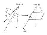
먼저, 영상 좌표의 기준이 되는 영상 좌표계는, 도 4에 도시된 바와 같이, 영상의 중심이 원점, 오른쪽 방향이 X축, 위쪽 방향이 Y축인 좌표계 시스템으로 정의하며, 영상 좌표계의 단위는 픽셀이다.First, as shown in FIG. 4, an image coordinate system that is a reference of image coordinates is defined as a coordinate system in which the center of the image is the origin, the X direction is the right direction, and the Y axis is the upper direction, and the unit of the image coordinate system is a pixel. .
다음으로, 공간 좌표계는 이동체(100)의 위치를 나타내는 기준되는 좌표계로 서, 통상적으로 도 5에 도시된 바와 같이 공간의 바닥면이 xy평면이 되는 좌표계로 정의한다.Next, the spatial coordinate system is a reference coordinate system indicating the position of the
도 5에서 h는 지면으로부터 카메라(110)의 높이를 의미하며, θt는 카메라(110)의 틸트(tilt) 각을 의미하고, θp는 카메라(110)의 팬(pan) 각도를 의미한다. 여기서, 틸트 각(θt)은 카메라(110)의 광학축(optical axis)이 z축과 이루는 각도로서 카메라(110)가 바닥면을 수직으로 바라볼 경우 틸트 각(θt)은 0도가 된다. 카메라(110)의 팬 각(θp)은 카메라(110)의 광학축을 xy 평면에서 사상(projection)시켰을 경우에 y축과 이루는 각을 의미한다. 즉, 카메라(110)의 팬 각은 z축을 회전축으로 한 카메라(110)의 회전각으로서 기준은 y축 방향이다.In FIG. 5, h denotes a height of the
영상 좌표로부터 공간 좌표로의 좌표 변환은 영상 평면(image plane)(500)이 바닥면과 수평이고, 영상 중심이 공간 좌표계의 z축 상에 위치하면, 즉 카메라(110)의 팬과 틸트가 없으면 비례식을 이용하여 계산할 수 있다. 따라서, 위치 검출부(114)는 영상 처리부(112)를 통해 검출된 영상 좌표로부터 먼저 팬과 틸트를 보상한 영상 좌표를 산출한다. 여기서, 팬과 틸트를 보상한 영상 좌표(x', y')는, 도 6에 도시된 바와 같이, 카메라(110)의 초점을 고정시키고, 카메라의 광학축(600)이 z축과 일치하도록 영상 평면(610)을 회전이동시켰을 경우에 광학 표식(100a)이 영상 맺힐 영상 좌표를 의미한다.The coordinate transformation from image coordinates to spatial coordinates is achieved when the
카메리의 초점 거리를 f라고 하고, 검출된 광원 표식의 영상 좌표를 (x, y) 라고하면, 팬 각과 틸트 각을 보상한 후의 영상 좌표(x' y')은 아래의 수학식 1에 의해서 구해진다.If the focal length of the camera is f and the image coordinate of the detected light source marker is (x, y), the image coordinate (x'y ') after compensating the pan angle and the tilt angle is expressed by

다음으로, 보정된 영상 좌표(x' y')로부터 비례식을 이용하여 광원 표식(110a)의 공간 좌표를 산출한다. 이때 카메라(110)의 설치 높이를 h라고 하며, 영상에서 하나의 픽셀이 차지하는 물리 거리를 s라고 하면, 광원 표식(110a)의 공간 좌표(X, Y)는 아래의 수학식 2에 의해서 산출된다.Next, the spatial coordinates of the

상기의 수학식 1과 수학식 2를 연산하면, 최종 이동체(100)에 장착된 광원 표식(100a)의 공간 좌표(X, Y)는 아래의 수학식 3에 의해서 산출된다.When the above equations (1) and (2) are calculated, the spatial coordinates (X, Y) of the light source marking (100a) mounted on the final moving object (100) are calculated by the following equation (3).

본 발명에 따르면, 하나의 카메라(110)와 이동체(100)에 설치된 광원 표식(100a)만을 사용하여 넓은 영역에서 움직이는 이동체(100)의 위치정보를 정밀하 게 산출할 수 있다.According to the present invention, it is possible to precisely calculate the position information of the moving
지금까지 본 발명의 일 실시예에 국한하여 설명하였으나 본 발명의 기술이 당업자에 의하여 용이하게 변형 실시될 가능성이 자명하다. 이러한 변형된 실시 예들은 본 발명의 특허청구범위에 기재된 기술사상에 포함된다고 하여야 할 것이다.It has been described so far limited to one embodiment of the present invention, it is obvious that the technology of the present invention can be easily modified by those skilled in the art. Such modified embodiments should be included in the technical spirit described in the claims of the present invention.
도 1은 본 발명의 바람직한 실시 예에 따른 이동체의 위치 검출 장치를 도시한 블록도이며,1 is a block diagram illustrating an apparatus for detecting a position of a moving object according to an exemplary embodiment of the present invention.
도 2는 본 발명에서 카메라의 설치 위치를 도시한 예시도이며,2 is an exemplary view showing an installation position of a camera in the present invention,
도 3a는 일반적인 카메라에서 획득한 영상을 도시한 도면이며,3A is a diagram illustrating an image acquired by a general camera.
도 3b는 본 발명에 따른 광학 필터가 구비된 카메라에서 획득한 영상을 도시한 도면이며,3B is a view showing an image obtained from a camera equipped with an optical filter according to the present invention.
도 4는 본 발명에서 적용되는 영상 좌표계를 도시한 도면이며,4 is a view showing an image coordinate system applied in the present invention,
도 5는 본 발명에서 적용되는 공간 좌표계를 도시한 도면이며,5 is a view showing a spatial coordinate system applied in the present invention,
도 6은 본 발명에서의 카메라의 팬과 틸트를 보상한 영상 좌표에 대해 설명하기 위한 도면이다.FIG. 6 is a diagram for describing image coordinates that compensate for pan and tilt of a camera according to the present invention.
<도면의 주요부분에 대한 부호의 설명><Description of the code | symbol about the principal part of drawing>
100 : 이동체 100a : 광학 표식100: moving
110 : 카메라 112 : 영상 처리부110: camera 112: image processing unit
114 : 위치 검출부114: position detection unit
Claims (13)
Translated fromKorean

Priority Applications (1)
| Application Number | Priority Date | Filing Date | Title |
|---|---|---|---|
| KR1020070084407AKR100913165B1 (en) | 2007-08-22 | 2007-08-22 | Position detecting apparatus and method of moving object |
Applications Claiming Priority (1)
| Application Number | Priority Date | Filing Date | Title |
|---|---|---|---|
| KR1020070084407AKR100913165B1 (en) | 2007-08-22 | 2007-08-22 | Position detecting apparatus and method of moving object |
Publications (2)
| Publication Number | Publication Date |
|---|---|
| KR20090020027Atrue KR20090020027A (en) | 2009-02-26 |
| KR100913165B1 KR100913165B1 (en) | 2009-08-19 |
Family
ID=40687553
Family Applications (1)
| Application Number | Title | Priority Date | Filing Date |
|---|---|---|---|
| KR1020070084407AExpired - Fee RelatedKR100913165B1 (en) | 2007-08-22 | 2007-08-22 | Position detecting apparatus and method of moving object |
Country Status (1)
| Country | Link |
|---|---|
| KR (1) | KR100913165B1 (en) |
Cited By (2)
| Publication number | Priority date | Publication date | Assignee | Title |
|---|---|---|---|---|
| KR101242936B1 (en)* | 2010-08-03 | 2013-03-12 | 주식회사 포스코 | Optical Emission Spectroscope Having Function Of Measuring Location Of Spark And Method For Measuring Location Of Spark In Optical Emission Spectroscope |
| CN110166648A (en)* | 2019-06-06 | 2019-08-23 | 杭州国翌科技有限公司 | A kind of camera detection locking means and device based on optical imagery |
Families Citing this family (2)
| Publication number | Priority date | Publication date | Assignee | Title |
|---|---|---|---|---|
| KR101431228B1 (en) | 2013-11-15 | 2014-08-18 | 김준환 | System and method for collecting location information of a plurality of light sticks |
| KR101944497B1 (en) | 2018-08-02 | 2019-01-31 | 블랙썬 주식회사 | Control system and method of unmanned driving vehicle using intelligent CCTV |
Family Cites Families (3)
| Publication number | Priority date | Publication date | Assignee | Title |
|---|---|---|---|---|
| JP2000165850A (en)* | 1998-11-25 | 2000-06-16 | Matsushita Electric Ind Co Ltd | Mobile tracking device |
| JP2001307072A (en) | 2000-04-21 | 2001-11-02 | Canon Inc | Recognition system, recognition device, recognition method, and storage medium |
| KR100691348B1 (en)* | 2005-12-21 | 2007-03-12 | 고정환 | Moving target tracking method and system using pan / tilt control based stereo camera |
- 2007
- 2007-08-22KRKR1020070084407Apatent/KR100913165B1/ennot_activeExpired - Fee Related
Cited By (2)
| Publication number | Priority date | Publication date | Assignee | Title |
|---|---|---|---|---|
| KR101242936B1 (en)* | 2010-08-03 | 2013-03-12 | 주식회사 포스코 | Optical Emission Spectroscope Having Function Of Measuring Location Of Spark And Method For Measuring Location Of Spark In Optical Emission Spectroscope |
| CN110166648A (en)* | 2019-06-06 | 2019-08-23 | 杭州国翌科技有限公司 | A kind of camera detection locking means and device based on optical imagery |
Also Published As
| Publication number | Publication date |
|---|---|
| KR100913165B1 (en) | 2009-08-19 |
Similar Documents
| Publication | Publication Date | Title |
|---|---|---|
| CN111521161B (en) | Method, survey device and machine-readable carrier for determining direction to target | |
| CN114585875B (en) | Metering system | |
| CN103314271B (en) | Geodetic device including thermal imaging camera | |
| US9341740B1 (en) | Optical ground tracking apparatus, systems, and methods | |
| CN101932905B (en) | Localization of a surveying instrument in relation to a ground mark | |
| US6031606A (en) | Process and device for rapid detection of the position of a target marking | |
| CN103827631B (en) | Measurement system and method for marking known target points in a coordinate system | |
| US20140198206A1 (en) | System and Method for Estimating the Position and Orientation of an Object using Optical Beacons | |
| US8542368B2 (en) | Position measuring apparatus and method | |
| JP2015537205A (en) | Method and apparatus for determining the posture of an object | |
| US20170046854A1 (en) | Measurement device | |
| KR100669250B1 (en) | Artificial Marker-based Real-time Positioning System and Method | |
| JP4396564B2 (en) | Object monitoring method and motion tracker using the same | |
| US10976158B2 (en) | Device and method to locate a measurement point with an image capture device | |
| US12025468B2 (en) | Optical sensor with overview camera | |
| KR100913165B1 (en) | Position detecting apparatus and method of moving object | |
| US20130162971A1 (en) | Optical system | |
| US20210140766A1 (en) | Optical surveying instrument | |
| CN110044334B (en) | Indoor space localization based on Voronoi diagram | |
| JPH07139942A (en) | Surveying apparatus | |
| CN115371544A (en) | Surveying device with image evaluator for determining spatial attitude of target axis | |
| KR20110073753A (en) | Angular output device of unmanned crane hook | |
| KR100898392B1 (en) | Mobile tracking device and method | |
| KR100698535B1 (en) | Position recognition device and method of mobile robot with tilt correction function | |
| KR101550563B1 (en) | Positioning Device and Method Using Illumination Lamp and Image Sensor |
Legal Events
| Date | Code | Title | Description |
|---|---|---|---|
| A201 | Request for examination | ||
| PA0109 | Patent application | St.27 status event code:A-0-1-A10-A12-nap-PA0109 | |
| PA0201 | Request for examination | St.27 status event code:A-1-2-D10-D11-exm-PA0201 | |
| D13-X000 | Search requested | St.27 status event code:A-1-2-D10-D13-srh-X000 | |
| D14-X000 | Search report completed | St.27 status event code:A-1-2-D10-D14-srh-X000 | |
| E902 | Notification of reason for refusal | ||
| PE0902 | Notice of grounds for rejection | St.27 status event code:A-1-2-D10-D21-exm-PE0902 | |
| T11-X000 | Administrative time limit extension requested | St.27 status event code:U-3-3-T10-T11-oth-X000 | |
| T11-X000 | Administrative time limit extension requested | St.27 status event code:U-3-3-T10-T11-oth-X000 | |
| E13-X000 | Pre-grant limitation requested | St.27 status event code:A-2-3-E10-E13-lim-X000 | |
| P11-X000 | Amendment of application requested | St.27 status event code:A-2-2-P10-P11-nap-X000 | |
| P13-X000 | Application amended | St.27 status event code:A-2-2-P10-P13-nap-X000 | |
| E902 | Notification of reason for refusal | ||
| PE0902 | Notice of grounds for rejection | St.27 status event code:A-1-2-D10-D21-exm-PE0902 | |
| PG1501 | Laying open of application | St.27 status event code:A-1-1-Q10-Q12-nap-PG1501 | |
| P11-X000 | Amendment of application requested | St.27 status event code:A-2-2-P10-P11-nap-X000 | |
| P13-X000 | Application amended | St.27 status event code:A-2-2-P10-P13-nap-X000 | |
| E701 | Decision to grant or registration of patent right | ||
| PE0701 | Decision of registration | St.27 status event code:A-1-2-D10-D22-exm-PE0701 | |
| PN2301 | Change of applicant | St.27 status event code:A-3-3-R10-R13-asn-PN2301 St.27 status event code:A-3-3-R10-R11-asn-PN2301 | |
| GRNT | Written decision to grant | ||
| PR0701 | Registration of establishment | St.27 status event code:A-2-4-F10-F11-exm-PR0701 | |
| PR1002 | Payment of registration fee | St.27 status event code:A-2-2-U10-U11-oth-PR1002 Fee payment year number:1 | |
| PG1601 | Publication of registration | St.27 status event code:A-4-4-Q10-Q13-nap-PG1601 | |
| FPAY | Annual fee payment | Payment date:20120730 Year of fee payment:4 | |
| PR1001 | Payment of annual fee | St.27 status event code:A-4-4-U10-U11-oth-PR1001 Fee payment year number:4 | |
| L13-X000 | Limitation or reissue of ip right requested | St.27 status event code:A-2-3-L10-L13-lim-X000 | |
| U15-X000 | Partial renewal or maintenance fee paid modifying the ip right scope | St.27 status event code:A-4-4-U10-U15-oth-X000 | |
| FPAY | Annual fee payment | Payment date:20130729 Year of fee payment:5 | |
| PR1001 | Payment of annual fee | St.27 status event code:A-4-4-U10-U11-oth-PR1001 Fee payment year number:5 | |
| FPAY | Annual fee payment | Payment date:20140728 Year of fee payment:6 | |
| PR1001 | Payment of annual fee | St.27 status event code:A-4-4-U10-U11-oth-PR1001 Fee payment year number:6 | |
| PN2301 | Change of applicant | St.27 status event code:A-5-5-R10-R13-asn-PN2301 St.27 status event code:A-5-5-R10-R11-asn-PN2301 | |
| PN2301 | Change of applicant | St.27 status event code:A-5-5-R10-R11-asn-PN2301 | |
| PN2301 | Change of applicant | St.27 status event code:A-5-5-R10-R14-asn-PN2301 | |
| FPAY | Annual fee payment | Payment date:20150722 Year of fee payment:7 | |
| PR1001 | Payment of annual fee | St.27 status event code:A-4-4-U10-U11-oth-PR1001 Fee payment year number:7 | |
| P14-X000 | Amendment of ip right document requested | St.27 status event code:A-5-5-P10-P14-nap-X000 | |
| P16-X000 | Ip right document amended | St.27 status event code:A-5-5-P10-P16-nap-X000 | |
| Q16-X000 | A copy of ip right certificate issued | St.27 status event code:A-4-4-Q10-Q16-nap-X000 | |
| R18-X000 | Changes to party contact information recorded | St.27 status event code:A-5-5-R10-R18-oth-X000 | |
| P14-X000 | Amendment of ip right document requested | St.27 status event code:A-5-5-P10-P14-nap-X000 | |
| P16-X000 | Ip right document amended | St.27 status event code:A-5-5-P10-P16-nap-X000 | |
| Q16-X000 | A copy of ip right certificate issued | St.27 status event code:A-4-4-Q10-Q16-nap-X000 | |
| FPAY | Annual fee payment | Payment date:20160520 Year of fee payment:8 | |
| PR1001 | Payment of annual fee | St.27 status event code:A-4-4-U10-U11-oth-PR1001 Fee payment year number:8 | |
| P22-X000 | Classification modified | St.27 status event code:A-4-4-P10-P22-nap-X000 | |
| P22-X000 | Classification modified | St.27 status event code:A-4-4-P10-P22-nap-X000 | |
| FPAY | Annual fee payment | Payment date:20170608 Year of fee payment:9 | |
| PR1001 | Payment of annual fee | St.27 status event code:A-4-4-U10-U11-oth-PR1001 Fee payment year number:9 | |
| FPAY | Annual fee payment | Payment date:20180718 Year of fee payment:10 | |
| PR1001 | Payment of annual fee | St.27 status event code:A-4-4-U10-U11-oth-PR1001 Fee payment year number:10 | |
| PC1903 | Unpaid annual fee | St.27 status event code:A-4-4-U10-U13-oth-PC1903 Not in force date:20190814 Payment event data comment text:Termination Category : DEFAULT_OF_REGISTRATION_FEE | |
| PC1903 | Unpaid annual fee | St.27 status event code:N-4-6-H10-H13-oth-PC1903 Ip right cessation event data comment text:Termination Category : DEFAULT_OF_REGISTRATION_FEE Not in force date:20190814 | |
| P22-X000 | Classification modified | St.27 status event code:A-4-4-P10-P22-nap-X000 |