KR20090012582A - Apparatus and method for synthesizing polymer on substrate - Google Patents
Apparatus and method for synthesizing polymer on substrateDownload PDFInfo
- Publication number
- KR20090012582A KR20090012582AKR1020070076518AKR20070076518AKR20090012582AKR 20090012582 AKR20090012582 AKR 20090012582AKR 1020070076518 AKR1020070076518 AKR 1020070076518AKR 20070076518 AKR20070076518 AKR 20070076518AKR 20090012582 AKR20090012582 AKR 20090012582A
- Authority
- KR
- South Korea
- Prior art keywords
- substrate
- chamber
- biopolymer
- reaction
- sample
- Prior art date
- Legal status (The legal status is an assumption and is not a legal conclusion. Google has not performed a legal analysis and makes no representation as to the accuracy of the status listed.)
- Withdrawn
Links
Images


Classifications
- H—ELECTRICITY
- H01—ELECTRIC ELEMENTS
- H01L—SEMICONDUCTOR DEVICES NOT COVERED BY CLASS H10
- H01L21/00—Processes or apparatus adapted for the manufacture or treatment of semiconductor or solid state devices or of parts thereof
- H01L21/67—Apparatus specially adapted for handling semiconductor or electric solid state devices during manufacture or treatment thereof; Apparatus specially adapted for handling wafers during manufacture or treatment of semiconductor or electric solid state devices or components ; Apparatus not specifically provided for elsewhere
- H01L21/67005—Apparatus not specifically provided for elsewhere
- H01L21/67011—Apparatus for manufacture or treatment
- H01L21/6715—Apparatus for applying a liquid, a resin, an ink or the like
- H—ELECTRICITY
- H01—ELECTRIC ELEMENTS
- H01L—SEMICONDUCTOR DEVICES NOT COVERED BY CLASS H10
- H01L21/00—Processes or apparatus adapted for the manufacture or treatment of semiconductor or solid state devices or of parts thereof
- B—PERFORMING OPERATIONS; TRANSPORTING
- B01—PHYSICAL OR CHEMICAL PROCESSES OR APPARATUS IN GENERAL
- B01J—CHEMICAL OR PHYSICAL PROCESSES, e.g. CATALYSIS OR COLLOID CHEMISTRY; THEIR RELEVANT APPARATUS
- B01J19/00—Chemical, physical or physico-chemical processes in general; Their relevant apparatus
- B01J19/0046—Sequential or parallel reactions, e.g. for the synthesis of polypeptides or polynucleotides; Apparatus and devices for combinatorial chemistry or for making molecular arrays
- H—ELECTRICITY
- H01—ELECTRIC ELEMENTS
- H01L—SEMICONDUCTOR DEVICES NOT COVERED BY CLASS H10
- H01L21/00—Processes or apparatus adapted for the manufacture or treatment of semiconductor or solid state devices or of parts thereof
- H01L21/02—Manufacture or treatment of semiconductor devices or of parts thereof
- H—ELECTRICITY
- H01—ELECTRIC ELEMENTS
- H01L—SEMICONDUCTOR DEVICES NOT COVERED BY CLASS H10
- H01L21/00—Processes or apparatus adapted for the manufacture or treatment of semiconductor or solid state devices or of parts thereof
- H01L21/67—Apparatus specially adapted for handling semiconductor or electric solid state devices during manufacture or treatment thereof; Apparatus specially adapted for handling wafers during manufacture or treatment of semiconductor or electric solid state devices or components ; Apparatus not specifically provided for elsewhere
- H01L21/67005—Apparatus not specifically provided for elsewhere
- H01L21/67011—Apparatus for manufacture or treatment
- H01L21/67126—Apparatus for sealing, encapsulating, glassing, decapsulating or the like
- B—PERFORMING OPERATIONS; TRANSPORTING
- B01—PHYSICAL OR CHEMICAL PROCESSES OR APPARATUS IN GENERAL
- B01J—CHEMICAL OR PHYSICAL PROCESSES, e.g. CATALYSIS OR COLLOID CHEMISTRY; THEIR RELEVANT APPARATUS
- B01J2219/00—Chemical, physical or physico-chemical processes in general; Their relevant apparatus
- B01J2219/00274—Sequential or parallel reactions; Apparatus and devices for combinatorial chemistry or for making arrays; Chemical library technology
- B01J2219/00277—Apparatus
- B01J2219/00479—Means for mixing reactants or products in the reaction vessels
- B01J2219/00484—Means for mixing reactants or products in the reaction vessels by shaking, vibrating or oscillating of the reaction vessels
- B—PERFORMING OPERATIONS; TRANSPORTING
- B01—PHYSICAL OR CHEMICAL PROCESSES OR APPARATUS IN GENERAL
- B01J—CHEMICAL OR PHYSICAL PROCESSES, e.g. CATALYSIS OR COLLOID CHEMISTRY; THEIR RELEVANT APPARATUS
- B01J2219/00—Chemical, physical or physico-chemical processes in general; Their relevant apparatus
- B01J2219/00274—Sequential or parallel reactions; Apparatus and devices for combinatorial chemistry or for making arrays; Chemical library technology
- B01J2219/00277—Apparatus
- B01J2219/00479—Means for mixing reactants or products in the reaction vessels
- B01J2219/00493—Means for mixing reactants or products in the reaction vessels by sparging or bubbling with gases
- B—PERFORMING OPERATIONS; TRANSPORTING
- B01—PHYSICAL OR CHEMICAL PROCESSES OR APPARATUS IN GENERAL
- B01J—CHEMICAL OR PHYSICAL PROCESSES, e.g. CATALYSIS OR COLLOID CHEMISTRY; THEIR RELEVANT APPARATUS
- B01J2219/00—Chemical, physical or physico-chemical processes in general; Their relevant apparatus
- B01J2219/00274—Sequential or parallel reactions; Apparatus and devices for combinatorial chemistry or for making arrays; Chemical library technology
- B01J2219/00277—Apparatus
- B01J2219/00497—Features relating to the solid phase supports
- B01J2219/00527—Sheets
- B01J2219/00529—DNA chips
- B—PERFORMING OPERATIONS; TRANSPORTING
- B01—PHYSICAL OR CHEMICAL PROCESSES OR APPARATUS IN GENERAL
- B01J—CHEMICAL OR PHYSICAL PROCESSES, e.g. CATALYSIS OR COLLOID CHEMISTRY; THEIR RELEVANT APPARATUS
- B01J2219/00—Chemical, physical or physico-chemical processes in general; Their relevant apparatus
- B01J2219/00274—Sequential or parallel reactions; Apparatus and devices for combinatorial chemistry or for making arrays; Chemical library technology
- B01J2219/00583—Features relative to the processes being carried out
- B01J2219/00603—Making arrays on substantially continuous surfaces
- B01J2219/00605—Making arrays on substantially continuous surfaces the compounds being directly bound or immobilised to solid supports
- B01J2219/00612—Making arrays on substantially continuous surfaces the compounds being directly bound or immobilised to solid supports the surface being inorganic
- B—PERFORMING OPERATIONS; TRANSPORTING
- B01—PHYSICAL OR CHEMICAL PROCESSES OR APPARATUS IN GENERAL
- B01J—CHEMICAL OR PHYSICAL PROCESSES, e.g. CATALYSIS OR COLLOID CHEMISTRY; THEIR RELEVANT APPARATUS
- B01J2219/00—Chemical, physical or physico-chemical processes in general; Their relevant apparatus
- B01J2219/00274—Sequential or parallel reactions; Apparatus and devices for combinatorial chemistry or for making arrays; Chemical library technology
- B01J2219/00718—Type of compounds synthesised
- B01J2219/0072—Organic compounds
- B01J2219/00722—Nucleotides
- B—PERFORMING OPERATIONS; TRANSPORTING
- B01—PHYSICAL OR CHEMICAL PROCESSES OR APPARATUS IN GENERAL
- B01J—CHEMICAL OR PHYSICAL PROCESSES, e.g. CATALYSIS OR COLLOID CHEMISTRY; THEIR RELEVANT APPARATUS
- B01J2219/00—Chemical, physical or physico-chemical processes in general; Their relevant apparatus
- B01J2219/00274—Sequential or parallel reactions; Apparatus and devices for combinatorial chemistry or for making arrays; Chemical library technology
- B01J2219/00718—Type of compounds synthesised
- B01J2219/0072—Organic compounds
- B01J2219/00725—Peptides
Landscapes
- Engineering & Computer Science (AREA)
- Physics & Mathematics (AREA)
- Condensed Matter Physics & Semiconductors (AREA)
- General Physics & Mathematics (AREA)
- Manufacturing & Machinery (AREA)
- Computer Hardware Design (AREA)
- Microelectronics & Electronic Packaging (AREA)
- Power Engineering (AREA)
- Chemical & Material Sciences (AREA)
- Organic Chemistry (AREA)
- Chemical Kinetics & Catalysis (AREA)
- Apparatus Associated With Microorganisms And Enzymes (AREA)
Abstract
Description
Translated fromKorean본 발명은 기판 상에 폴리머를 합성하는 장치 및 그 방법에 관한 것으로서, 보다 상세하게는 반도체 기판 상에 바이오 폴리머를 합성하는 장치 및 반도체 기판 상에 바이오 폴리머를 형성하는 방법에 관한 것이다.The present invention relates to an apparatus and a method for synthesizing a polymer on a substrate, and more particularly, to an apparatus for synthesizing a biopolymer on a semiconductor substrate and a method for forming a biopolymer on a semiconductor substrate.
기판 상에 폴리머를 합성할 필요성은 반도체 분야 뿐만 아니라, 다양한 기술 분야에서 인식되고 있다. 특히, 최근에는 슬라이드 기판 상에 올리고머 프로브와 같은 바이오 폴리머를 고정한 마이크로 어레이가 소개되었으며, 이러한 마이크로 어레이를 형성하는 데에도 폴리머 합성 기술이 도입되고 있다.The necessity of synthesizing polymers on substrates has been recognized in various technical fields as well as in the semiconductor field. In particular, recently, a micro array in which a biopolymer such as an oligomeric probe is immobilized on a slide substrate has been introduced, and a polymer synthesis technique is also introduced to form such a micro array.
예를 들어, 전통적으로 반도체 분야에서 널리 사용되어 왔던 포토리소그래피(photolithography) 기술이 마이크로 어레이의 올리고머 프로브를 합성하는 데에 응용된다. 포토리소그래피를 이용한 올리고머 프로브의 합성은 예를 들어 기판 상에 광분해성 보호기가 결합된 피커플링 물질을 고정하고, 광 마스크에 의한 선택적 노광으로 광분해성 보호기를 제거하고, 합성 대상이 되는 모노머를 제공하여 광분해성 보호기가 제거된 피커플링 물질과 반응시키는 단계를 거친다.For example, photolithography techniques, which have traditionally been widely used in the semiconductor field, are applied to synthesize oligomer probes of micro arrays. Synthesis of oligomer probes using photolithography, for example, immobilizes a coupled material with a photodegradable protecting group on a substrate, removes the photodegradable protecting group by selective exposure with a photomask, and provides a monomer to be synthesized. To react with the uncoupled material from which the photodegradable protecting group has been removed.
25mer의 올리고머 프로브를 합성하기 위해 작게는 25회, 많게는 100회 이상의 합성 단계를 거친다. 따라서, 각 단계에서 합성 대상이 되는 모노머와 피커플링 물질 간의 반응 수율은 전체 공정 수율에 매우 큰 영향을 미치게 된다. 따라서, 각 단계별 반응 수율을 최대화할 것이 절실히 요구된다.The synthesis of 25mer oligomeric probes is carried out at least 25, more than 100 synthesis steps. Therefore, the reaction yield between the monomer and the coupling material to be synthesized in each step has a very large effect on the overall process yield. Therefore, there is an urgent need to maximize the reaction yield for each step.
이에, 본 발명이 해결하고자 하는 과제는 반응 수율이 향상된 바이오 폴리머 합성 장치를 제공하고자 하는 것이다.Accordingly, an object of the present invention is to provide a biopolymer synthesis apparatus with improved reaction yield.
본 발명이 해결하고자 하는 다른 과제는 반응 수율이 향상된 바이오 폴리머의 합성 방법을 제공하고자 하는 것이다.Another object of the present invention is to provide a method for synthesizing a biopolymer having improved reaction yield.
본 발명의 과제들은 이상에서 언급한 과제들로 제한되지 않으며, 언급되지 않은 또 다른 과제들은 아래의 기재로부터 당업자에게 명확하게 이해될 수 있을 것이다.The objects of the present invention are not limited to the above-mentioned objects, and other objects that are not mentioned will be clearly understood by those skilled in the art from the following description.
상기 과제를 해결하기 위한 본 발명의 일 실시예에 따른 바이오 폴리머 합성 장치는 바이오 폴리머가 합성되는 기판이 배치되는 반응 챔버, 및 상기 반응 챔버를 셰이킹하는 셰이킹 장치를 포함한다.According to an aspect of the present invention, a biopolymer synthesis apparatus includes a reaction chamber in which a substrate on which a biopolymer is synthesized is disposed, and a shaking device for shaking the reaction chamber.
상기 다른 과제를 해결하기 위한 본 발명의 일 실시예에 따른 바이오 폴리머의 합성 방법은 반응 챔버 내에 바이오 폴리머가 합성되는 기판을 배치하고, 상기 기판 상에 바이오 폴리머 합성용 시료를 제공하고, 상기 반응 챔버를 셰이킹하는 것을 포함한다.According to another aspect of the present invention, there is provided a method for synthesizing a biopolymer, in which a substrate on which a biopolymer is synthesized is disposed in a reaction chamber, and a sample for biopolymer synthesis is provided on the substrate. Shaking hands.
기타 실시예의 구체적인 사항들은 상세한 설명 및 도면들에 포함되어 있다.Specific details of other embodiments are included in the detailed description and drawings.
본 발명의 실시예들에 따른 바이오 폴리머 합성 장치 및 바이오 폴리머 합성 방법에 의하면, 합성 대상이 되는 바이오 폴리머 합성용 시료의 퍼짐성이 개선되어 반응 수율이 개선된다. 나아가, 본 발명의 실시예들에 따른 바이오 폴리머 합성 장치에 의하면, 반응 공간 내에 공급된 바이오 폴리머 합성용 시료가 기판의 배면에 오염되는 것을 방지할 수 있다.According to the biopolymer synthesis apparatus and the biopolymer synthesis method according to the embodiments of the present invention, the spreadability of the biopolymer synthesis sample to be synthesized is improved to improve the reaction yield. Furthermore, according to the biopolymer synthesis apparatus according to the embodiments of the present invention, it is possible to prevent the biopolymer synthesis sample supplied in the reaction space from being contaminated on the back surface of the substrate.
본 발명의 이점 및 특징, 그리고 그것들을 달성하는 방법은 첨부되는 도면과 함께 상세하게 후술되어 있는 실시예들을 참조하면 명확해질 것이다. 그러나 본 발명은 이하에서 개시되는 실시예들에 한정되는 것이 아니라 서로 다른 다양한 형태로 구현될 것이며, 단지 본 실시예들은 본 발명의 개시가 완전하도록 하며, 본 발명이 속하는 기술분야에서 통상의 지식을 가진 자에게 발명의 범주를 완전하게 알려주기 위해 제공되는 것이며, 본 발명은 청구항의 범주에 의해 정의될 뿐이다.Advantages and features of the present invention and methods for achieving them will be apparent with reference to the embodiments described below in detail with the accompanying drawings. However, the present invention is not limited to the embodiments disclosed below, but will be implemented in various forms, and only the present embodiments are intended to complete the disclosure of the present invention, and the general knowledge in the art to which the present invention pertains. It is provided to fully convey the scope of the invention to those skilled in the art, and the present invention is defined only by the scope of the claims.
따라서, 몇몇 실시예에서, 잘 알려진 공정 단계들, 잘 알려진 구조 및 잘 알려진 기술들은 본 발명이 모호하게 해석되는 것을 피하기 위하여 구체적으로 설명되지 않는다.Thus, in some embodiments, well known process steps, well known structures and well known techniques are not described in detail in order to avoid obscuring the present invention.
본 명세서에서 사용된 용어는 실시예들을 설명하기 위한 것이며 본 발명을 제한하고자 하는 것은 아니다. 본 명세서에서, 단수형은 문구에서 특별히 언급하지 않는한 복수형도 포함한다. 명세서에서 사용되는 포함한다(comprises) 및/또는 포함하는(comprising)은 언급된 구성요소, 단계, 동작 및/또는 소자 이외의 하나 이상의 다른 구성요소, 단계, 동작 및/또는 소자의 존재 또는 추가를 배제하지 않는 의미로 사용한다. 그리고, "및/또는"은 언급된 아이템들의 각각 및 하나 이상의 모든 조합을 포함한다. 명세서 전체에 걸쳐 동일 참조 부호는 동일 구성 요소를 지칭한다.The terminology used herein is for the purpose of describing particular embodiments only and is not intended to be limiting of the invention. In this specification, the singular also includes the plural unless specifically stated otherwise in the phrase. As used herein, including and / or comprising includes the presence or addition of one or more other components, steps, operations and / or elements other than the components, steps, operations and / or elements mentioned. Use in the sense that does not exclude. And “and / or” includes each and all combinations of one or more of the items mentioned. Like reference numerals refer to like elements throughout.
이하, 첨부된 도면을 참고로 하여 본 발명의 실시예들에 따른 바이오 폴리머 합성 장치에 대해 상세히 설명한다.Hereinafter, a biopolymer synthesis apparatus according to embodiments of the present invention will be described in detail with reference to the accompanying drawings.
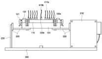
도 1은 본 발명의 일 실시예에 따른 바이오 폴리머 합성 장치의 평면도이다. 도 2는 도 1의 정면도이다. 도 3은 본 발명의 일 실시예에 따른 반응 챔버의 사시도이다.1 is a plan view of a biopolymer synthesis apparatus according to an embodiment of the present invention. 2 is a front view of FIG. 1. 3 is a perspective view of a reaction chamber according to an embodiment of the present invention.
도 1 내지 도 3을 참조하면, 본 발명의 일 실시예에 따른 바이오 폴리머 합성 장치는 반응 챔버(100) 및 셰이킹 장치(200)를 포함한다.1 to 3, a biopolymer synthesis apparatus according to an embodiment of the present invention includes a
반응 챔버(100)에는 바이오 폴리머(biopolymer)가 합성될 기판(도 4a, 도 4b의 '10' 참조)이 배치된다.In the
기판(도 4a, 도 4b의 '10' 참조) 상에 합성될 목적(target) 바이오 폴리머는 생체 내에서 합성되거나, 생체를 구성하는 폴리머를 포함한다. 바이오 폴리머는 예를 들어, 2 이상의 모노머(monomer)로 이루어진다. 상기 모노머의 예로는 뉴클레오사이드, 뉴클레오타이드, 아미노산, 펩티드 등을 들 수 있다The target biopolymer to be synthesized on the substrate (see '10' in FIGS. 4A and 4B) includes a polymer synthesized in vivo or constituting the living body. Biopolymers consist of, for example, two or more monomers. Examples of the monomers include nucleosides, nucleotides, amino acids, peptides, and the like.
상기 뉴클레오사이드 및 뉴클레오타이드는 공지의 퓨린 및 피리미딘 염기를 포함할 뿐만 아니라 메틸화된 퓨린 또는 피리미딘, 아실화된 퓨린 또는 피리미딘 등을 포함할 수 있다. 또, 상기 뉴클레오사이드 및 뉴클레오타이드는 종래의 리보스 및 디옥시리보스 당을 포함할 뿐만 아니라 하나 이상의 하이드록실기가 할로겐 원자 또는 지방족으로 치환되거나 에테르, 아민 등의 작용기가 결합한 변형된 당을 포함할 수 있다.The nucleosides and nucleotides include known purine and pyrimidine bases, as well as methylated purines or pyrimidines, acylated purines or pyrimidines, and the like. In addition, the nucleosides and nucleotides may include conventional ribose and deoxyribose sugars, as well as modified sugars in which one or more hydroxyl groups are substituted with halogen atoms or aliphatic groups, or functional groups such as ethers and amines are bonded. .
상기 아미노산은 자연에서 발견되는 아미노산의 L-, D-, 및 비키랄성(nonchiral)형 아미노산뿐만 아니라 변형 아미노산(modified amino acid), 또는 아미노산 유사체(analog) 등일 수 있다.The amino acids may be L-, D-, and nonchiral amino acids of amino acids found in nature, as well as modified amino acids, amino acid analogs, and the like.
상기 펩티드는 아미노산의 카르복실기와 다른 아미노산의 아미노기 사이의 아미드 결합에 의해 생성된 화합물을 포함한다.The peptide includes a compound produced by an amide bond between a carboxyl group of an amino acid and an amino group of another amino acid.
반응 챔버(100) 내에서, 목적으로 하는 바이오 폴리머는 상기 모노머들을 각 모노머 단위로 기판 상에 순차적으로 공유결합 반응시킴으로써 합성되거나, 상기 예시된 모노머들이 2 이상 공유 결합되어 이루어진 바이오 폴리머를 기판(도 4a, 도 4b의 '10' 참조) 상의 다른 모노머 또는 바이오 폴리머와 공유결합 반응을 수행함으로써 합성될 수 있다.In the
기판(10)은 베이스 기판으로서 가요성(flexible) 또는 강성(rigid) 기판을 포함할 수 있다. 가요성 기판은 나일론, 니트로셀룰로오스 등의 멤브레인 또는 플라스틱 필름 등일 수 있다. 강성 기판은 반도체 웨이퍼 기판, 소다 석회 유리와 같은 투명 유리 기판 등일 수 있다. 상술한 바이오 폴리머 합성을 실효적으로 수행하기 위하여 베이스 기판 상에는 모노머, 또는 바이오 폴리머나 기타 다른 유기 또는 무기 링커 등이 고정되어 있을 수 있다.The
반응 챔버(100)의 형상 및 사이즈(size)는 배치되는 기판에 따라 결정된다. 예를 들어, 기판(10)의 베이스 기판으로서 원형의 실리콘 웨이퍼를 적용할 경우, 반응 챔버(100)의 전체적인 형상은 원통형일 수 있다.The shape and size of the
예시적인 실시예에서 반응 챔버(100)는 챔버 바디(110) 및 챔버 커버(120)를 포함한다. 챔버 커버(120)는 챔버 바디(110)에 결합 가능하도록 설치된다. 여기서, "결합 가능하다"고 하는 것은 챔버 커버(120)가 챔버 바디(110)에 결합할 뿐만 아니라, 챔버 바디(110)로부터 완전 분리되거나, 적어도 부분적으로 분리될 수 있음을 의미한다. 챔버 바디(110)와 챔버 커버(120)를 적어도 부분적으로 분리하면, 반응 챔버(100)의 내부가 개방되어, 바이오 폴리머가 합성될 기판(10)이 반응 챔버(100) 내에 용이하게 배치될 수 있다. 챔버 바디(110)와 챔버 커버(120)가 결합되면, 반응 챔버(100)의 내부 공간이 실질적으로 밀폐되며, 나아가 밀폐된 반응 공간을 제공할 수 있어, 안정적인 반응 공정 제어에 유리하다. 본 명세서에서, "공간이 실질적으로 밀폐된다" 함은 공간이 외부와 완전히 단절되어 있는 경우 뿐만 아니라, 소통이 제어될 수 있는 소정의 관 또는 홀에 의해 외부 구조물과 연결되어 있는 경우를 포함하는 의미로 정의된다.In an exemplary embodiment, the
챔버 바디(110)와 챔버 커버(120)의 결합은 예컨대, 제1 결합 수단(131)에 의해 구현될 수 있다. 도 1 내지 도 3에 예시적으로 도시된 제1 결합 수단의 예는 클램프이다. 클램프는 챔버 바디(110) 및/또는 챔버 커버(120)의 외측면을 따라, 복수개가 구비될 수 있다. 그러나, 이에 제한되는 것은 아니며, 제1 결합 수 단(131)으로서 채택되는 예 및 그 수는 다양하게 변형 가능함은 자명하다.The coupling of the
본 발명의 몇몇 예시적인 실시예는 챔버 바디(110)와 챔버 커버(120)의 완전한 분리를 막기 위하여 챔버 바디(110)와 챔버 커버(120)의 일측 테두리에 연결 핀(133)을 구비할 수 있다.Some exemplary embodiments of the present invention may include a connecting
내부 구조를 포함하여 반응 챔버(100)를 더욱 구체적으로 예시하기 위하여 도 4a 및 도 4b가 참조된다. 도 4a 및 도 4b는 본 발명의 일 실시예에 따른 반응 챔버의 단면도들로서, 각각 도 4a는 챔버 바디로부터 챔버 커버를 분리한 경우를, 도 4b는 챔버 커버를 챔버 바디에 결합시킨 경우를 나타낸다.Reference is made to FIGS. 4A and 4B to more specifically illustrate the
도 4a 및 도 4b에 예시적으로 도시된 바와 같이, 챔버 바디(110) 및 챔버 커버(120)는 각각 테두리부(111, 121)와 중앙부(112, 122)간 단차가 있다. 즉, 챔버 바디(110)와 챔버 커버(120)는 예컨대, 테두리부(111, 121)가 중앙부(112, 122)보다 융기되어 있는 용기(container) 형상을 갖는다. 챔버 바디(110)와 챔버 커버(120)의 테두리부(111, 121)는 실질적으로 평탄한 표면(111s, 121s)을 갖는다. 따라서, 챔버 바디(110)와 챔버 커버(120)가 결합되면, 챔버 바디(110) 테두리부(111)의 표면(111s)과 챔버 커버(120) 테두리부(121)의 표면(121s)이 서로 맞닿아 밀착되어 결합면을 이루며, 챔버 바디(110)의 중앙부(112) 및 챔버 커버(120)의 중앙부(122)는 서로 이격된다.As exemplarily shown in FIGS. 4A and 4B, the
본 발명의 몇몇 예시적인 실시예는 챔버 바디(110)와 챔버 커버(120)의 테두리부(111, 121)에 구비된 제2 결합 수단(132)을 더 포함할 수 있다. 제2 결합 수단(132)은 예를 들어, 챔버 커버(120)의 테두리부(121)에 돌출되도록 형성된 결합 나사(125) 및 챔버 바디(110)의 테두리부(111)에 형성된 결합 홈(115)을 포함할 수 있다. 제2 결합 수단(132)은 상술한 제1 결합 수단(131)과 함께, 챔버 바디(110)와 챔버 커버(120)간 결합이 비틀림 없이 정밀하고 안정적으로 이루어지도록 하는 역할을 한다.Some exemplary embodiments of the present invention may further include a second coupling means 132 provided at the
챔버 바디(110)의 테두리부(111) 내측에는 기판(10)이 배치되는 기판 안착단(114)이 구비된다. 기판 안착단(114)은 도 4a 및 도 4b에 도시된 바와 같이, 테두리부(111)의 내측에서 소정 폭을 갖도록 형성될 수 있다. 기판 안착단(114)보다 내측에 위치하는 챔버 바디(110)의 중앙부(112)는 기판 안착단(114)보다 더욱 낮은 단차를 가질 수 있다. 이 경우, 기판 안착단(114)에 배치되는 기판(10)과 챔버 바디(110)의 중앙부(112) 사이에는 소정의 에어 스페이스(air space)(AS)가 정의된다. 기판(10)은 테두리만이 기판 안착단(114)에 배치되고, 중앙부는 챔버 바디(110)로부터 떨어져 있게 된다.The
다른 예로서, 도면으로 도시하지는 않았지만, 기판 안착단은 챔버 바디의 중앙부를 모두 점유하도록, 챔버 바디의 중앙부 전체에 걸쳐 평탄하게 형성될 수도 있다. 이 경우, 기판의 배면 전체가 기판 안착단에 의해 지지될 것이다.As another example, although not shown in the drawings, the substrate seating end may be formed flat throughout the center of the chamber body to occupy all of the center of the chamber body. In this case, the entire backside of the substrate will be supported by the substrate seating end.
본 발명의 몇몇 예시적인 실시예에 따른 챔버 커버(120)의 테두리부(121)는 챔버 바디(110)의 테두리부(111)보다 폭이 넓도록 형성된다. 따라서, 챔버 커버(120)와 챔버 바디(120)가 결합되면, 챔버 커버(120)의 테두리부(121)가 챔버 바디(110)의 테두리부(111)보다 내측(중앙부 측)으로 돌출되어, 챔버 커버(120)의 테두리부(121)의 일부는 챔버 바디(110)의 기판 안착단(114)과 오버랩된다. 따라서, 챔버 바디(110)의 기판 안착단(114)으로부터 융기된 테두리부(111)의 높이를 기판(10)의 두께와 실질적으로 동일하게 설정하면, 기판 안착단(114)에 배치된 기판(10)의 테두리가 챔버 커버(120)의 테두리부(121)의 표면(121s)에 밀착되어 커버될 수 있다. 챔버 커버(120)의 테두리부(121)에 의해 밀착 커버되는 기판(10)의 테두리는 바이오 폴리머 합성 반응이 일어나지 않는 희생 영역이 된다. 공정 수율 관점에서는 희생 영역의 폭이 작은 것이 유리하나, 후술하는 기판(10) 배면 오염 방지를 위한 마진(margine)을 위해서는 그 폭이 어느 정도 확보되는 것이 바람직하다. 상기 관점에서 챔버 커버(120)의 테두리부(121)에 의해 밀착 커버되는 기판(10) 테두리의 폭은, 예컨대, 약 1 내지 20mm일 수 있다.The
한편, 기판 안착단(114)에 배치된 기판(10)과 챔버 커버(120)의 중앙부(122)는 챔버 커버(120)의 중앙부(122)로부터 융기된 테두리부(121)의 높이만큼 이격된다. 이와 같이 이격된 공간은 바이오 폴리머가 합성되는 반응 공간(RS)을 제공하게 된다. 즉, 반응 공간(RS)은 기판 커버(120)의 중앙부(122), 기판 커버(120)의 테두리부(121)의 측벽, 및 기판(10)의 상면에 의해 한정된다. 반응 공간(RS) 내부에서의 이루어지는 다양한 반응 상황을 용이하게 관찰하기 위하여, 챔버 커버(120)의 적어도 중앙부(122)는 투명한 재질, 예컨대 유리, 석영 등으로 이루어질 수 있다. 즉, 도 1 내지 도 3에 도시된 바와 같이, 챔버 커버(120)의 중앙부(122)에는 윈도우(window)가 구비될 수 있다.Meanwhile, the
반응 공간(RS)의 크기(체적)는 제공되는 바이오 폴리머 합성용 시료의 양, 그의 퍼짐성, 및 습윤성 등에 관계되며, 챔버 커버(120)의 중앙부(122)와 기판(10) 의 상면간 이격거리, 다시 말하면 기판 커버(120)의 중앙부(122)로부터 융기된 테두리부(121)의 높이에 의해 좌우된다. 상기 관점을 고려한 챔버 커버(120)의 중앙부(122)와 기판(10)의 상면간 이격거리, 다시 말하면 기판 커버(120)의 중앙부(122)로부터 융기된 테두리부(121)의 높이는 예컨대 약 0.2 내지 10mm일 수 있다.The size (volume) of the reaction space RS is related to the amount of the biopolymer synthesis sample provided, its spreadability and wettability, and the separation distance between the
반응 공간(RS)은 상술한 바와 같이 반응 챔버(100)의 밀폐된 내부 공간에 제공되므로, 반응 공간(RS)의 경우에도 외부에 대하여 실질적으로 밀폐된다. 나아가, 기판(10) 상면의 테두리가 챔버 커버(120)의 테두리부(122)에 의해 밀착 커버되고, 기판(10) 배면이 챔버 바디(110)의 기판 안착부(114)에 의해 지지되므로, 기판(10) 배면과 챔버 바디(110)의 중앙부(112) 사이에 소정의 에어 스페이스(AS)가 정의된다고 할지라도, 에어 스페이스(AS)는 반응 공간(RS)과 공간적으로 분리된다. 다시 말하면, 반응 공간(RS)은 에어 스페이스(AS)에 대하여도 실질적으로 밀폐된다. 따라서, 반응 공간(RS) 내로 바이오 폴리머 합성용 시료 등이 공급되더라도, 기판(10)의 배면으로 침투되지 않아 기판(10) 배면으로의 오염이 방지될 수 있다. 기판(10) 배면의 오염은 예를 들어, 바이오 물질의 분석 오류나, 후속 포토 리소그래피 장치의 오동작 등을 유발한다는 측면에서, 기판(10) 배면 오염 방지는 유효한 의의를 갖는다.Since the reaction space RS is provided in the sealed inner space of the
상기 관점에서 기판(10) 배면의 오염 방지를 더욱 담보하기 위하여, 본 발명의 몇몇 예시적인 실시예는 챔버 바디(110)의 기판 안착단(114) 및/또는 챔버 커버(120)의 테두리부(121)를 따라 형성된 개스킷(gasket)을 포함할 수 있다. 개스킷 으로는 예컨대, 오링(o-ring)(116, 112)이 적용될 수 있다. 챔버 바디(110)의 기판 안착단(114)에 형성된 오링(116)은 기판(10)의 배면과, 챔버 커버(120)의 테두리부(121)에 형성된 오링(126)은 기판(10)의 상면과 각각 직접 접하면서, 폴리머 합성용 시료 등과 같은 유체의 침투를 더욱 확실하게 차단한다.In order to further ensure contamination prevention of the backside of the
반응 공간(RS)은 적어도 하나의 유체 공급관(410a) 및 유체 배출관(410b)과 공간적으로 연결된다. 이를 위하여 챔버 바디(110)와 챔버 커버(120) 중 적어도 하나는 각 유체 공급관(410a) 및 유체 배출관(410b)과 연결되는 복수의 관통홀(128)을 구비한다. 도 4a 및 도 4b에서는 관통홀(128)이 챔버 커버(120)에 형성되어 있는 것이 예시되어 있다. 관통홀(128)의 일단은 챔버 커버(120) 테두리부(121)의 측벽을 개구하고, 타단은 도 2 및 도 3에 도시된 바와 같이 커넥터(129a, 129b)를 통하여 유체 공급관(410a) 또는 유체 배출관(410b)과 연결된다. 유체 공급관(410a)(또는 배출관(410b)) 및 관통홀(128)을 통하여, 반응 공간(RS) 내부로(또는 내부로부터) 바이오 폴리머 합성용 시료, 활성화제(activator), 비활성 기체 등이 공급(또는 배출)된다. 몇몇 유체 공급관(410a)은 버블 생성용 비활성 기체 전용 공급관일 수 있다. 유체 공급관(410a) 및 유체 배출관(410b)에 대한 더욱 상세한 내용은 후술된다.The reaction space RS is spatially connected to the at least one
도 5는 본 발명의 몇몇 다른 실시예들에 따른 반응 챔버의 단면도이다. 도 5의 반응 챔버(100_1)는 기판(10)이 그 상면이 아래를 향하도록 뒤집혀서 배치되고, 반응 공간(RS)이 기판(10)과 챔버 바디(110_1)의 중앙부(112) 사이에 정의되는 방식을 채용한다. 이를 위하여, 챔버 바디(110_1)의 기판 안착단(114)과 기판 안착 단(114)으로부터 내측에 위치하는 챔버 바디(110_1)의 중앙부(112)는 기판 안착단(114)과 소정 단차를 갖는다. 챔버 바디(110_1)의 중앙부(112)와 기판(10) 간 이격거리는 반응 공간(RS)의 크기를 좌우하게 될 것임은 물론이다. 챔버 바디(110_1)의 중앙부(112)와 기판(10) 간 이격거리는 챔버 바디(110_1)의 중앙부(112)를 기준으로 한 기판 안착단(114)의 높이와 실질적으로 동일하다. 도 4a 및 도 4b의 경우와 유사하게 상기 이격 거리 또는 챔버 바디(110_1)의 중앙부(112)에 대한 기판 안착단(114)의 높이는 약 0.2mm 내지 10mm일 수 있다. 한편, 반응 공간(RS)이 챔버 바디(110_1) 측에 의해 정의되므로, 유체 공급관 또는 유체 배출관과 연결되는 관통홀(128)도 챔버 커버(120_1)가 아닌 챔버 바디(110_1)에 구비된다.5 is a cross-sectional view of a reaction chamber in accordance with some other embodiments of the present invention. In the reaction chamber 100_1 of FIG. 5, the
이하, 상술한 유체 공급관 및 유체 배출관을 통한 유체의 흐름에 대하여 더욱 상세히 설명한다. 도 6은 본 발명의 몇몇 실시예에 따른 유체 흐름 시스템에 관한 개략도이다.Hereinafter, the flow of the fluid through the fluid supply pipe and the fluid discharge pipe described above will be described in more detail. 6 is a schematic diagram of a fluid flow system in accordance with some embodiments of the present invention.
본 발명의 몇몇 실시예에 따른 유체 흐름 시스템은 유체 공급관(410a) 및 유체 배출관(410b) 이외에, 제1 및 제2 비활성 기체 공급 탱크(433, 434), 제1 및 제2 시료 공급 탱크(431, 432), 복수의 유체 흐름관(410), 각 유체 흐름관(410)을 연결하는 복수의 밸브(421-425)를 더 포함한다.The fluid flow system according to some embodiments of the present invention includes first and second inert
제1 및 제2 시료 공급 탱크(431, 432)는 바이오 폴리머의 합성에 필요한 시료를 저장하고, 이를 유체 공급관(410a)을 통해 반응 챔버의 반응 공간으로 제공하는 역할을 한다. 제1 시료 공급 탱크(431)에 의해 제공되는 제1 바이오 폴리머 합성용 시료의 예는 상술한 바 있는 뉴클레오사이드, 뉴클레오타이드, 아미노산, 펩 티드 등의 모노머나 그 화합물을 포함한다. 예를 들어, 인-시츄로 올리고뉴클레오타이드 프로브를 합성하려고 하는 경우, 상기 바이오 폴리머 합성용 시료는 아데닌(A), 구아닌(G), 티민(T), 시토신(C)이나, 우라실(U) 중 어느 하나를 염기로 갖는 뉴클레오타이드 포스포아미디트 모노머로서, 광분해성 보호기 또는 산분해성 보호기가 커플링되어 뉴클레오타이드 포스포아미디트 모노머일 수 있다.The first and second
제2 시료 공급 탱크(432)에 의해 제공되는 제2 바이오 폴리머 합성용 시료의 예는 상기와 같은 모노머들의 합성을 활성화하는 활성화제(activator)나 세정제 등을 들 수 있다. 상기 뉴클레오타이드 포스포아미디트 모노머의 합성을 활성화하는 활성화제로는 아세토니트릴(acetonitrile) 용액이 예시되지만, 활성화제가 이상의 예시에 제한되지 않음은 물론이다. 경우에 따라, 제2 시료 공급 탱크(432)는 생략되거나, 하나의 제2 시료 공급 탱크(432)가 복수개의 유체 공급관(410a)과 연결될 수 있다.Examples of the second biopolymer synthesis sample provided by the second
제1 및 제2 비활성 기체 공급 탱크(433, 434)는 비활성 기체, 예컨대 질소(N2)를 공급한다. 제1 비활성 기체 공급 탱크(433)에 의해 공급된 기체는 유체 흐름관(410)을 통해 제1 시료 공급 탱크(431)에 제공되어 소정 압력을 부여함으로써, 제1 바이오 폴리머 합성용 시료를 유체 흐름관(410) 측으로 밀어내는 역할을 한다. 적절한 압력 조절을 위하여 제1 비활성 기체 공급 탱크(433)와 제1 시료 공급 탱크(431) 사이에는 압력 조절기(436)가 설치된다.The first and second inert
제2 비활성 기체 공급 탱크(434)에 의해 공급되는 비활성 기체는 유체 흐름관(410)을 통해 제2 시료 공급 탱크(432)에 제공되어 소정 압력을 부여함으로써, 제2 바이오 폴리머 합성용 시료를 유체 흐름관(410) 측으로 밀어낸다. 나아가, 비활성 기체는 제2 시료 공급 탱크(432)를 거치지 않고 직접 유체 흐름관(410) 및 유체 공급관(410a)을 통해 반응 공간(RS)에 제공되어 반응 공간(RS)을 비활성화된 상태로 유지하고, 반응 공간(RS)으로부터 원하지 않는 시료가 유체 공급관(410a) 측으로 역류하는 것을 방지한다.The inert gas supplied by the second inert
복수의 밸브(421-425)는 3 방향 솔레노이드 밸브(3 way solenoid valve), 및 2 방향 솔레노이드 밸브(2 way solenoid valve)를 포함할 수 있다. 도 6의 예시에서 제1, 제2 및 제4 밸브(421, 422, 424)는 3 방향 솔레노이드 밸브이고, 제3 및 제5 밸브(423, 425)는 2 방향 솔레노이드 밸브이다.The plurality of valves 421-425 may include a three way solenoid valve, and a two way solenoid valve. In the example of FIG. 6, the first, second and
제1 밸브(421)의 3 단자는 각각 유체 흐름관(410)을 통하여 제1 시료 공급 탱크(431), 제2 밸브(422), 및 제4 밸브(424)와 연결된다. 제1 밸브(421)와 제1 시료 공급 탱크(431) 사이의 유체 공급관(410)에는 압력 센서(436)가 구비될 수 있다. 제2 밸브(422)의 3 단자 중 1 단자는 유체 공급관(410a)을 통하여 반응 공간(RS)과 연결된다. 제2 밸브(422)의 다른 2 단자는 각각 유체 흐름관(410)을 통하여 제1 밸브(421) 및 제3 밸브(423)와 연결된다. 제3 밸브(423)의 2 단자 중 1 단자는 유체 공급관(410)을 통하여 제2 밸브(422)와 연결되어 있고, 다른 단자는 배수부(out)와 연결되어 있다. 제4 밸브(424)의 3단자는 각각 유체 흐름관(410)을 통하여 제1 밸브(421), 제2 시료 공급 탱크(432), 및 제5 밸브(435)와 연결되어 있다. 제5 밸브(435)의 2 단자는 유체 공급관(410a)을 통하여 각각 제4 밸브(424) 및 제2 비활성 기체 공급 탱크(434)와 연결된다.Three terminals of the
유체 배출관(410b)은 일단이 반응 공간(RS)과 연결되고 타단은 배수부(out)와 연결된다. 유체 배출관(410b)에는 배출 펌프(436)가 설치된다.One end of the
이와 같은 유체 흐름 시스템에 의한 유체 흐름의 예를 설명하면, 먼저, 압력 조절기(435)를 조절하여 제1 비활성 기체 공급 탱크(433)로부터 비활성 기체를 제1 시료 공급 탱크(431)로 제공하면, 제1 바이오 폴리머 합성용 시료가 가압되어 유체 흐름관(410) 측으로 분출되어 제1 밸브(421)에 다다른다. 이때, 제1 밸브(421)가 제4 밸브(424) 측으로의 통로는 막고 제2 밸브(422) 측으로의 통로만을 형성하도록 조절하면, 제1 바이오 폴리머 합성용 시료가 제2 밸브(422) 측으로 공급된다. 제2 밸브(422)의 유체 공급관(410a) 측으로의 통로만을 형성시키면, 제1 바이오 폴리머 합성용 시료는 유체 공급관(410a)을 통하여 반응 공간(RS)으로 공급된다.Referring to an example of the fluid flow by such a fluid flow system, first, by adjusting the
제1 바이오 폴리머 합성용 시료의 공급 중, 또는 공급 후에 반응 공간(RS)으로 제2 바이오 폴리머 합성용 시료를 공급하기 위하여, 제2 비활성 기체 공급 탱크(434)로부터 비활성 기체를 제2 시료 공급 탱크(432)로 제공한다. 이때, 제5 밸브(425)는 폐쇄하여 비활성 기체가 제2 시료 공급 탱크(432) 측으로만 제공되도록 조절한다. 그 결과, 비활성 기체가 제2 바이오 폴리머 합성용 시료를 가압하여 제2 바이오 폴리머 합성용 시료를 제4 밸브(424) 측으로 분출한다. 이때, 제4 밸브(424)는 제1 밸브(421) 측으로만 통로를 형성하도록 조절된다. 제1 밸브(421)에 도달된 제2 바이오 폴리머 합성용 시료는 제1 밸브(421)의 선택적 통로 조절에 의해 제2 밸브(422) 측으로 진행된다. 이후, 제2 밸브(422)의 유체 공급관(410a) 측으로의 통로만을 형성시키면, 제2 바이오 폴리머 합성용 시료는 유체 공급관(410a) 을 통하여 반응 공간(RS)으로 공급된다.Inert gas from the second inert
제1 및/또는 제2 바이오 폴리머 합성용 시료의 공급 중, 또는 공급 후에 반응 공간(RS)으로 비활성 기체를 제공하기 위해서는 제5 밸브(425)를 개방하고 제4 밸브(424)가 제5 밸브(425) 및 제1 밸브(421) 사이의 구간만을 통과시키도록 조절한다. 이후의 단계는 제2 바이오 폴리머 합성용 시료의 제공과 동일하다. 반응 공간(RS)으로 비활성 기체를 제공하는 것은 반응 공간(RS)을 비활성화된 상태로 유지하고, 반응 공간(RS)으로부터 제1 및/또는 제2 바이오 폴리머 합성용 시료가 유체 공급관(410a) 측을 통해 억류되어 유체 흐름관(410)이 오염되는 것을 방지하는데 유효하다. 나아가, 반응 공간 (RS)내의 제1 및/또는 제2 바이오 폴리머 합성용 시료에 버블을 생성함으로써, 제1 및/또는 제2 바이오 폴리머 합성용 시료의 혼합성 및 퍼짐성을 개선하여 반응 수율을 개선하는데에도 효과가 있다. 특히, 버블 생성을 위한 비활성 기체의 공급은 본 실시예에서처럼 제1 및/또는 제2 바이오 폴리머 합성용 시료를 공급하는 유체 공급관(410a)을 이용하지 않고, 그 대신에 적어도 하나의 독립적인 전용 유체 공급관을 통해 이루어질 수 있다.In order to provide an inert gas to the reaction space RS during or after the supply of the first and / or second biopolymer synthesis sample, the
비활성 기체를 사용하여 유체 흐름관(410)을 세정하기 위해서는 상술한 비활성 기체를 공급하는 것과 동일한 방법으로 진행하되, 제2 밸브(422)에서 유체 공급관(410a) 측으로의 통로는 폐쇄하고, 제3 밸브(423) 측으로의 통로만을 개방한다.In order to clean the
반응 공간으로부터 반응에 참여하고 남은 시료를 제거하기 위해서는 배출 펌프(436)를 작동하여 반응 공간(RS) 내에 음압을 걸어준다. 그러면, 남은 시료가 유체 배출관(410b)을 통하여 배수부(out)로 배출된다.In order to remove a sample remaining in the reaction from the reaction space, the
계속해서, 본 발명의 몇몇 실시예에 따른 바이오 폴리머 합성 장치의 셰이킹 장치(200)에 대해 설명한다. 셰이킹 장치(200)는 반응 챔버(100)를 셰이킹(shaking)하는 장치이다. 본 명세서 상에서 셰이킹이란, 진동, 흔들림, 왕복 운동, 회전 운동, 롤링 운동 등과 같이, 비정지 상태를 의미하는 모든 동작을 포함한다. 반응 공간(RS) 내에 바이오 폴리머 합성용 시료를 제공하고 반응 챔버(100)를 셰이킹하면, 바이오 폴리머 합성용 시료가 고르게 퍼져, 기판(10) 상의 모든 면에서 균일하게 개선된 바이오 폴리머 합성이 이루어진다. 특히, 기판(10)의 표면이 고르지 않거나, 시료의 점성이 높아 퍼짐성이 낮은 경우, 셰이킹 장치(200)에 의한 셰이킹으로 반응 수율을 개선할 수 있다. 또, 시료의 양이 적더라도 기판(10) 표면이 고르게 습윤(wetting)되기 때문에, 상대적으로 적은 시료의 양으로 바이오 폴리머를 합성할 수 있는 장점이 있다. 본 명세서에서는 셰이킹의 일예로서, 롤링 운동을 예로 하여 셰이킹 장치(200)를 설명하기로 한다.Subsequently, the shaking
도 7은 본 발명의 몇몇 실시예에 따른 바이오 폴리머 합성 장치의 셰이킹 동작을 설명하기 위한 측면도이다.7 is a side view for explaining a shaking operation of the biopolymer synthesis apparatus according to some embodiments of the present invention.
도 1, 도 2 및 도 7을 참조하면, 본 발명의 몇몇 실시예에 따른 바이오 폴리머 합성 장치의 셰이킹 장치(200)는 구동축(220) 및 구동축(220)을 구동하는 서보 모터(servo motor)(210)를 포함한다.1, 2 and 7, the shaking
구동축(220)의 일단은 서보 모터(220)에 연결되고 타단은 지지대(230)에 연결 설치된다. 반응 챔버(100)는 구동축(220) 중간에 고정 설치된다. 서보 모터(210)와 지지대(230)는 플레이트(300) 상에 설치된다.One end of the
서보 모터(210)는 구동축(220)을 회전시킬 뿐만 아니라, 구동축(220)을 소정 시간동안 소정 주기로 롤링 운동시킨다. 반응 챔버(100)는 구동축(220)에 고정 설치되어 있기 때문에, 구동축(220)의 회전에 따라 함께 회전하고, 구동축(220)의 롤링에 따라 함께 롤링한다.The
반응 챔버(100)의 회전은 후술하는 바와 같이 바이오 폴리머 합성용 시료의 배출시에 수행될 수 있다. 반응 챔버(100)의 최대 회전 각도는 예컨대, ±90°일 수 있지만, 이에 제한되지 않음은 물론이다.Rotation of the
반응 챔버(100)의 롤링은 반응 공간(RS) 내에서 바이오 폴리머의 합성이 이루어질 때에 수행될 수 있다. 반응 챔버(100)의 최대 롤링 각도(±θ)는 반응 공간(RS) 내에 채워져 있는 바이오 폴리머 합성용 시료의 양 등에 따라 다르지만, 예컨대, ±10°(즉, -10°~ 10°의 각도로 롤링함) 내지 ±60°(즉, -60°~ 60°의 각도로 롤링함)의 범위를 가질 수 있다.Rolling of the
이하, 본 발명의 일 실시예에 따른 바이오 폴리머의 합성 방법에 대해 설명한다. 본 발명의 일 실시예에 따른 바이오 폴리머 합성 방법은 반응 챔버 내에 바이오 폴리머가 합성되는 기판을 배치하고, 기판 상에 바이오 폴리머 합성용 시료를 제공하고, 반응 챔버를 셰이킹하는 것을 포함한다. 상술한 바와 같이 반응 챔버의 셰이킹은 바이오 폴리머 합성용 시료가 기판의 전면에 고르게 퍼지는 것을 촉진하여 반응성을 향상시킨다. 따라서, 바이오 폴리머 합성 수율이 향상된다.Hereinafter, a method of synthesizing a biopolymer according to an embodiment of the present invention will be described. A biopolymer synthesis method according to an embodiment of the present invention includes placing a substrate on which a biopolymer is synthesized in a reaction chamber, providing a sample for biopolymer synthesis on the substrate, and shaking the reaction chamber. As described above, the shaking of the reaction chamber promotes evenly spreading of the sample for biopolymer synthesis on the front surface of the substrate, thereby improving reactivity. Thus, biopolymer synthesis yield is improved.
더욱 구체적인 설명을 위하여 도 8 내지 도 11이 참조된다. 도 8 내지 도 11은 본 발명의 일 실시예에 따른 바이오 폴리머 합성 방법을 설명하기 위한 공정 단 면도들이다.Reference is made to FIGS. 8 to 11 for more detailed description. 8 to 11 are process steps for explaining a biopolymer synthesis method according to an embodiment of the present invention.
도 8 및 도 9는 기판을 바이오 폴리머의 합성에 필요한 상태, 예컨대 바이오 폴리머와 커플링할 수 있는 작용기를 노출하는 단계를 예시적으로 도시한다. 도 8을 참조하면, 베이스 기판(510) 상에 모노머가 커플링되어 있는 기판을 준비한다. 여기서, 모노머는 아데닌(A), 구아닌(G), 티민(T), 시토신(C)이나, 우라실(U) 중 어느 하나를 염기로 갖는 뉴클레오타이드 포스포아미디트 모노머일 수 있다. 상기 각 모노머는 광분해성 보호기(X)에 의해 다른 모노머와 커플링할 수 있는 작용기(도 9의 '535' 참조)가 보호되어 있다. 상기 다른 모노머와 커플링할 수 있는 작용기(535)로는 하이드록실기, 알데히드기, 카르복실기, 아미노기, 아미드기, 티올기, 할로기, 또는 술포네이트기 등이 예시될 수 있다.8 and 9 exemplarily illustrate exposing a substrate to a state necessary for the synthesis of the biopolymer, such as a functional group capable of coupling with the biopolymer. Referring to FIG. 8, a substrate on which a monomer is coupled onto a
베이스 기판(510) 상에는 복수의 셀 액티브 영역(cell active region)(520) 및 이들을 물리적 및/또는 화학적으로 분리하는 셀 분리 영역(cell isolation region)(525)이 형성되어 있다. 셀 액티브 영역(520)은 PE-TEOS막, HDP 산화막, P-SiH4 산화막, 열산화막 등의 실리콘 산화막, 하프늄 실리케이트, 지르코늄 실리케이트 등의 실리케이트, 실리콘 산질화막, 하프늄 산질화막, 지르코늄산질화막 등의 금속 산질화막, 티타늄 산화막, 탄탈륨 산화막, 알루미늄 산화막, 하프늄 산화막, 지르코늄 산화막, ITO 등의 금속 산화막, 폴리이미드, 폴리아민, 금, 은, 구리, 팔라듐 등의 금속, 또는 폴리스티렌, 폴리아크릴산, 폴리비닐 등의 폴리머 등으로 이루어질 수 있다. 각 모노머들은 셀 액티브 영역에 직접 또는 링커를 매개하여 커플링될 수 있다.A plurality of cell
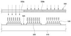
이어서, 투광 영역(550a) 및 차광 영역(550b)을 포함하는 마스크(550)를 이용하여 셀 액티브 영역(520)을 선택적으로 노광한다. 그러면, 도 9에 도시된 바와 같이 노광된 셀 액티브 영역(550)에서는 모노머와 커플링되어 있는 광분해성 보호기(X)가 제거되어 다른 모노머와 커플링할 수 있는 작용기(535)가 노출된다.Subsequently, the cell
도 10 및 도 11은 기판 상에 바이오 폴리머를 합성하는 단계를 도시한다. 도 10을 참조하면, 도 9의 결과물 상에 바이오 폴리머 합성용 시료(540)를 제공한다. 여기서, 바이오 폴리머 합성용 시료(540)는 광분해성 보호기(X)에 의해 보호되어 있는, 시토신(C)을 염기로 갖는 뉴클레오타이드 포스포아미디트 모노머(CX)인 것으로 가정한다. 제공된 바이오 폴리머 합성용 시료(540)는 노광에 의해 다른 모노머와 커플링할 수 있는 작용기(535)가 노출되어 있는 모노머(A)에만 선택적으로 반응한다. 이때, 기판을 셰이킹하면서 커플링 반응을 진행하면, 기판 전체에 걸쳐 고른 반응을 유도되어, 반응 수율이 향상될 수 있다. 이후, 유기 용매 등을 이용하여 잔류하는 바이오 폴리머 합성용 시료(540)를 제거하면, 도 11에 도시된 바와 같이, 특정 셀 액티브 영역(520)에 A와 CX가 커플링된 바이오 폴리머(ACX)가 합성된다.10 and 11 illustrate the steps of synthesizing a biopolymer on a substrate. Referring to FIG. 10, a
도 12a 내지 도 12d는 도 10의 단계를 본 발명의 몇몇 실시예에 따른 바이오 폴리머 합성 장치를 이용하여 수행하는 예시적인 방법을 도시한다.12A-12D illustrate an exemplary method of performing the steps of FIG. 10 using a biopolymer synthesis apparatus in accordance with some embodiments of the present invention.
도 12a를 참조하면, 기판(10)을 바이오 폴리머 합성 장치의 챔버 바디(110)의 기판 안착단(114)에 배치하고, 제1 결합 수단(131) 및 제2 결합 수단(132)을 이용하여 챔버 커버(120)를 챔버 바디(110)에 결합시킨다. 이때, 기판(10)의 테두리는 챔버 커버(120)의 테두리부(121)에 의해 밀착되어 커버된다. 그 결과, 기판(10) 과 챔버 커버(120) 사이에 실질적으로 밀폐된 반응 공간(RS)이 정의된다.Referring to FIG. 12A, the
이어서, 유체 공급관(410a), 커넥터(129a), 및 관통홀(128)을 통하여 바이오 폴리머 합성용 시료(540)를 반응 공간 내로 공급한다. 바이오 폴리머 합성용 시료(540)의 공급량은 예컨대 반응 공간(RS)의 약 60%를 채울 수 있는 양일 수 있다. 그러나, 이에 제한되는 것은 아니며, 점도, 퍼짐성, 후속하는 셰이킹 조건(속도, 시간, 각도) 등을 고려하여 약 10% 내지 90%의 범위 내에서 조절될 수 있다. 기판(10)은 테두리가 챔버 커버(120)의 테두리부(121) 및 챔버 바디(110)의 기판 안착단(114)에 밀착되어 있으며, 나아가 오링(116, 126)에 의해 그 소통이 완전히 차단되어 있으므로, 바이오 폴리머 합성용 시료가 에어 스페이서(AS) 측으로 침투하여 기판(10)의 배면을 오염시키는 것을 방지할 수 있음은 앞서 설명한 바와 같다.Subsequently, the
도 12b 및 도 12c는 반응 챔버(110)를 ±θ의 최대 롤링 각도로 롤링시키는 단계를 도시한다. 도 12b의 상태와 도 12c의 상태를 반복적으로 수행하는 롤링 운동에 의해 바이오 폴리머 합성용 시료(540)가 기판(10)의 전면에 고르게 퍼지게 되며, 반응 수율이 증가된다. 예를 들어, 최대 롤링 각도를 약 ±30°로 하여 롤링할 경우, 셰이킹을 하지 않은 경우에 비하여 약 1 내지 30%의 반응 수율이 향상될 수 있다.12B and 12C illustrate rolling the
롤링은 바이오 폴리머 합성용 시료(540)가 유체 공급관(410a)으로 역류할 수 있는 가능성을 수반한다. 롤링시에 유체 공급관(410a) 측으로 비활성 기체를 공급하면, 그 압력에 의해 역류가 억제 또는 최소화될 수 있다. 복수개의 유체 공급관(410a)이 구비된 경우, 모든 유체 공급관(410a)을 통하여 비활성 기체를 공급할 수 있다.Rolling involves the possibility that the
나아가, 비활성 기체의 공급은 바이오 폴리머 합성용 시료(540)에 버블을 생성할 수 있다. 바이오 폴리머 합성용 시료에 버블이 생성되면, 바이오 폴리머 합성용 시료(540)의 이동성 및 반응성을 더욱 향상시켜 반응 수율을 증가시킨다. 버블 생성을 위한 비활성 기체의 공급은 롤링과는 별도로 이루어질 수 있으며, 바이오 폴리머 합성용 시료를 공급하는 유체 공급관(410a)과는 별개로, 전용의 버블 생성용 유체 공급관을 통하여 이루어질 수도 있다.Furthermore, the supply of inert gas may generate bubbles in the
도 12d는 반응 완료된 바이오 폴리머 합성용 시료를 배출하는 방법을 도시한다. 도 12를 참조하면, 유체 배출관(410b)이 아래쪽에 위치하도록 반응 챔버(110)를 90°만큼 회전시킨다. 이어서, 배출 펌프(436)를 작동하여 반응 완료된 바이오 폴리머 합성용 시료(540)를 관통홀(280), 커넥터(129b), 및 유체 배출관(410b)을 통해 배수부 측으로 배출한다. 반응 챔버(110)의 회전에 의해 유체 배출관(410b)을 아래쪽에 위치하도록 하면, 중력의 작용으로 유체 배출이 더욱 촉진될 수 있다. 따라서, 상대적으로 낮은 구동력을 갖는 배출 펌프(436)도 적용될 수 있는 이점이 있다. 나아가 배출 펌프(436)를 구비하지 않고, 오직 중력에 의해서면 배출하는 것이 고려될 수 있다. 이 경우, 유체 배출관(410b)에는 밸브가 구비된다.Figure 12d shows a method for discharging the reaction completed biopolymer synthesis sample. Referring to FIG. 12, the
본 발명에 관한 보다 상세한 내용은 다음의 구체적인 실험예들을 통하여 설명하며, 여기에 기재되지 않은 내용은 이 기술 분야에서 숙련된 자이면 충분히 기술적으로 유추할 수 있는 것이므로 설명을 생략한다.More detailed information about the present invention will be described through the following specific experimental examples, and details not described herein will be omitted because it can be inferred technically by those skilled in the art.
<실험예>Experimental Example
도 8 내지 도 11을 참조하여 설명한 방법을 사용하여 반도체 웨이퍼 기판 상에 22㎛의 피치(pitch)를 갖는 셀 액티브 영역 내에 4mer의 DNA 모노머로 이루어진 테스트 프로브를 합성하였다. 기판 상의 DNA 모노머 합성은 본 발명의 실시예들에 따른 바이오 폴리머 합성 장치의 반응 챔버 내에서 수행되었다. 이때, 기판을 약 ±30°의 최대 롤링 각도로 롤링하면서 DNA 모노머를 합성하였다.Using the method described with reference to FIGS. 8 to 11, a test probe composed of 4mer of DNA monomer in a cell active region having a pitch of 22 μm was synthesized on a semiconductor wafer substrate. DNA monomer synthesis on the substrate was performed in the reaction chamber of the biopolymer synthesis apparatus according to the embodiments of the present invention. At this time, the DNA monomer was synthesized by rolling the substrate at a maximum rolling angle of about ± 30 °.
<비교실험예>Comparative Example
기판 상의 DNA 모노머 합성을 통상적인 반응 챔버에서 수행하고, 합성시 롤링하지 않은 것을 제외하고는 상기 실험예와 동일한 방법을 사용하여 4mer의 DNA 모노머로 이루어진 비교 테스트 프로브를 합성하였다.DNA monomer synthesis on the substrate was carried out in a conventional reaction chamber, and a comparative test probe composed of 4mer of DNA monomer was synthesized using the same method as the above Experimental Example, except that the synthesis was not rolled.
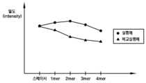
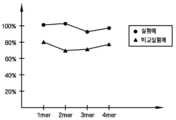
실험예에 의한 테스트 프로브 및 비교실험예에 의한 비교 테스트 프로브에 대하여 각 합성 단계마다 염색 라벨링(dye labeling)을 수행하여 밀도(intensity)를 조사하였다. 이를 반응 수율로 환산하여 도 13에 도시하였다.The test probes according to the experimental example and the comparative test probes according to the comparative example were subjected to dye labeling (dye labeling) at each synthesis step to investigate the intensity. This is shown in FIG. 13 in terms of reaction yield.
도 13a는 본 발명의 실시예들에 따른 바이오 폴리머 합성 방법에 따른 롤링을 수반한 경우(실험예)와 롤링을 수반하지 않는 경우(비교실험예)에 각각 합성되는 바이오 폴리머의 밀도를 비교한 그래프이고, 도 13b는 각각의 DNA 모노머 합성 단계에 따른 반응 수율을 비교한 그래프이다. 도 13a에서 스페이서(spacer)는 기판 상에 DNA 모노머를 전혀 합성하지 않은 경우의 밀도를 나타낸다.13A is a graph comparing the densities of biopolymers synthesized in the case of rolling with the biopolymer synthesis method according to the embodiments of the present invention (Experimental Example) and without the rolling (Comparative Experimental Example). 13B is a graph comparing reaction yields according to respective DNA monomer synthesis steps. In FIG. 13A, a spacer represents a density when no DNA monomer is synthesized on the substrate.
도 13a 및 도 13b에 도시된 바와 같이, 비교실험예에 따라 롤링을 수반하지 않고 합성된 비교 테스트 프로브의 반응 수율은 평균 약 80% 정도인데 반해, 실험예에 따라 기판을 약 ±30°의 최대 롤링 각도로 롤링하면서 합성된 테스트 프로브 의 반응 수율은 약 96%로 약 16% 정도 더 큼을 확인할 수 있다. 따라서, 이들의 누적 밀도의 차이는 합성을 거듭할수록 더욱 심화됨을 알 수 있다. 이와 같이 테스트 프로브의 반응 수율이 비교 테스트 프로브의 반응 수율보다 높은 것은 롤링 운동을 통하여 합성 대상이 되는 DNA 모노머가 기판의 전면에 고루 퍼져 반응성이 개선되었기 때문인 것으로 분석된다.As shown in FIGS. 13A and 13B, the reaction yield of the comparative test probes synthesized without rolling according to the comparative example is about 80% on average, whereas the substrate has a maximum of about ± 30 ° according to the example. It can be seen that the reaction yield of the synthesized test probe while rolling at a rolling angle is about 96%, which is about 16% higher. Therefore, it can be seen that the difference in their cumulative densities increases as the synthesis is repeated. As such, the reaction yield of the test probe is higher than that of the comparative test probe because the DNA monomer, which is a synthesis target, is evenly spread over the front surface of the substrate through the rolling motion to improve the reactivity.
이상 첨부된 도면을 참조하여 본 발명의 실시예들을 설명하였지만, 본 발명이 속하는 기술분야에서 통상의 지식을 가진 자는 본 발명이 그 기술적 사상이나 필수적인 특징을 변경하지 않고서 다른 구체적인 형태로 실시될 수 있다는 것을 이해할 수 있을 것이다. 그러므로 이상에서 기술한 실시예들을 모든 면에서 예시적인 것이며 한정적이 아닌 것으로 이해해야만 한다.Although embodiments of the present invention have been described above with reference to the accompanying drawings, those skilled in the art to which the present invention pertains may implement the present invention in other specific forms without changing the technical spirit or essential features thereof. I can understand that. Therefore, it should be understood that the embodiments described above are exemplary in all respects and not restrictive.
도 1은 본 발명의 일 실시예에 따른 바이오 폴리머 합성 장치의 평면도이다.1 is a plan view of a biopolymer synthesis apparatus according to an embodiment of the present invention.
도 2는 도 1의 정면도이다.2 is a front view of FIG. 1.
도 3은 본 발명의 일 실시예에 따른 반응 챔버의 사시도이다.3 is a perspective view of a reaction chamber according to an embodiment of the present invention.
도 4a 및 도 4b는 본 발명의 일 실시예에 따른 반응 챔버의 단면도들이다.4A and 4B are cross-sectional views of a reaction chamber in accordance with one embodiment of the present invention.
도 5는 본 발명의 몇몇 다른 실시예들에 따른 반응 챔버의 단면도이다.5 is a cross-sectional view of a reaction chamber in accordance with some other embodiments of the present invention.
도 6은 본 발명의 몇몇 실시예에 따른 유체 흐름 시스템에 관한 개략도이다.6 is a schematic diagram of a fluid flow system in accordance with some embodiments of the present invention.
도 7은 본 발명의 몇몇 실시예에 따른 바이오 폴리머 합성 장치의 셰이킹 동작을 설명하기 위한 측면도이다.7 is a side view for explaining a shaking operation of the biopolymer synthesis apparatus according to some embodiments of the present invention.
도 8 내지 도 11은 본 발명의 일 실시예에 따른 바이오 폴리머 합성 방법을 설명하기 위한 공정 단면도들이다.8 to 11 are cross-sectional views illustrating a biopolymer synthesis method according to an embodiment of the present invention.
도 12a 내지 도 12d는 본 발명의 일 실시예에 따른 바이오 폴리머 합성 장치를 이용하여 기판 상에 바이오 폴리머를 합성하는 예시적인 방법을 설명하기 위한 단면도들이다.12A-12D are cross-sectional views illustrating an exemplary method of synthesizing a biopolymer on a substrate using a biopolymer synthesis apparatus according to one embodiment of the invention.
도 13a는 본 발명의 실시예들에 따른 바이오 폴리머 합성 방법에 따른 롤링을 수반한 경우와 롤링을 수반하지 않는 경우에 각각 합성되는 바이오 폴리머의 밀도를 비교한 그래프이다.FIG. 13A is a graph comparing density of biopolymers synthesized when rolling is performed according to the biopolymer synthesis method according to the embodiments of the present invention and when rolling is not performed.
도 13b는 본 발명의 실시예들에 따른 바이오 폴리머 합성 방법에 따른 롤링을 수반한 경우와 롤링을 수반하지 않는 경우에 각각 합성되는 바이오 폴리머의 DNA 모노머 합성 단계에 따른 반응 수율을 비교한 그래프이다.FIG. 13B is a graph comparing reaction yields according to the step of synthesizing DNA monomers of biopolymers synthesized with and without rolling according to the biopolymer synthesis method according to the embodiments of the present invention.
<도면의 주요부분에 대한 부호의 설명><Description of the symbols for the main parts of the drawings>
100: 반응 챔버 110: 챔버 바디100: reaction chamber 110: chamber body
120: 챔버 커버 200: 셰이킹 장치120: chamber cover 200: shaking device
210: 서보 모터 220: 구동축210: servo motor 220: drive shaft
300: 플레이트 410: 유체 흐름관300: plate 410: fluid flow tube
410a: 유체 공급관 410b: 유체 배출관410a:
Claims (21)
Translated fromKoreanPriority Applications (2)
| Application Number | Priority Date | Filing Date | Title |
|---|---|---|---|
| KR1020070076518AKR20090012582A (en) | 2007-07-30 | 2007-07-30 | Apparatus and method for synthesizing polymer on substrate |
| US12/220,923US20090131635A1 (en) | 2007-07-30 | 2008-07-30 | Method for synthesizing polymer on substrate |
Applications Claiming Priority (1)
| Application Number | Priority Date | Filing Date | Title |
|---|---|---|---|
| KR1020070076518AKR20090012582A (en) | 2007-07-30 | 2007-07-30 | Apparatus and method for synthesizing polymer on substrate |
Publications (1)
| Publication Number | Publication Date |
|---|---|
| KR20090012582Atrue KR20090012582A (en) | 2009-02-04 |
Family
ID=40642657
Family Applications (1)
| Application Number | Title | Priority Date | Filing Date |
|---|---|---|---|
| KR1020070076518AWithdrawnKR20090012582A (en) | 2007-07-30 | 2007-07-30 | Apparatus and method for synthesizing polymer on substrate |
Country Status (2)
| Country | Link |
|---|---|
| US (1) | US20090131635A1 (en) |
| KR (1) | KR20090012582A (en) |
Family Cites Families (6)
| Publication number | Priority date | Publication date | Assignee | Title |
|---|---|---|---|---|
| US5424186A (en)* | 1989-06-07 | 1995-06-13 | Affymax Technologies N.V. | Very large scale immobilized polymer synthesis |
| US5143854A (en)* | 1989-06-07 | 1992-09-01 | Affymax Technologies N.V. | Large scale photolithographic solid phase synthesis of polypeptides and receptor binding screening thereof |
| US5384261A (en)* | 1991-11-22 | 1995-01-24 | Affymax Technologies N.V. | Very large scale immobilized polymer synthesis using mechanically directed flow paths |
| US7294478B1 (en)* | 2001-06-06 | 2007-11-13 | Rosetta Inpharmatics Llc | Microarray reaction cartridge |
| US6846454B2 (en)* | 2001-12-24 | 2005-01-25 | Agilent Technologies, Inc. | Fluid exit in reaction chambers |
| US7083975B2 (en)* | 2002-02-01 | 2006-08-01 | Roland Green | Microarray synthesis instrument and method |
- 2007
- 2007-07-30KRKR1020070076518Apatent/KR20090012582A/ennot_activeWithdrawn
- 2008
- 2008-07-30USUS12/220,923patent/US20090131635A1/ennot_activeAbandoned
Also Published As
| Publication number | Publication date |
|---|---|
| US20090131635A1 (en) | 2009-05-21 |
Similar Documents
| Publication | Publication Date | Title |
|---|---|---|
| CN101473220B (en) | Electrode array device having an adsorbed porous reaction layer | |
| US7153689B2 (en) | Apparatus and methods for cleaning and priming droplet dispensing devices | |
| US6790620B2 (en) | Small volume chambers | |
| AU751956B2 (en) | Solvent for biopolymer synthesis, solvent microdroplets and methods of use | |
| US6846454B2 (en) | Fluid exit in reaction chambers | |
| JP4990476B2 (en) | Focused acoustic energy in the preparation and screening of combinatorial libraries | |
| US6440669B1 (en) | Methods for applying small volumes of reagents | |
| US20060182664A1 (en) | Flow cell devices, systems and methods of using the same | |
| US20030118482A1 (en) | Atmospheric control in reaction chambers | |
| US6406851B1 (en) | Method for coating a substrate quickly and uniformly with a small volume of fluid | |
| US20040175710A1 (en) | Method for in situ, on-chip chemical synthesis | |
| CN115920796A (en) | Functionalized surfaces and preparation thereof | |
| US9283535B2 (en) | Synthesis of oligomers in arrays | |
| US20030003504A1 (en) | Flow cell for chemical reactions | |
| CN101156062B (en) | Electrode array device with adsorbed porous reaction layer connected with linker parts | |
| US20100298171A1 (en) | Apparatus for polymer synthesis | |
| JP2006519285A (en) | Systems and methods for polymer synthesis | |
| US11067571B2 (en) | Surface functionalization | |
| KR20090012582A (en) | Apparatus and method for synthesizing polymer on substrate | |
| KR20090034636A (en) | Apparatus and method for biopolymer synthesis, method for recovering biopolymer synthesis sample | |
| US20030232140A1 (en) | Methods for reagent removal in flow chambers | |
| WO2023170258A1 (en) | Apparatus for enzymatic synthesis of a plurality of polynucleotides comprising a condensation trap | |
| US20100052207A1 (en) | Method of Preparing Microarray by Using Optically Transparent Array Mold with Concave Portion | |
| CN120344317A (en) | Method and apparatus for culturing droplets |
Legal Events
| Date | Code | Title | Description |
|---|---|---|---|
| PA0109 | Patent application | Patent event code:PA01091R01D Comment text:Patent Application Patent event date:20070730 | |
| PG1501 | Laying open of application | ||
| PC1203 | Withdrawal of no request for examination | ||
| WITN | Application deemed withdrawn, e.g. because no request for examination was filed or no examination fee was paid |