KR20090009868A - Fixing plate having bone growth promoting material and method of use - Google Patents
Fixing plate having bone growth promoting material and method of useDownload PDFInfo
- Publication number
- KR20090009868A KR20090009868AKR1020087027946AKR20087027946AKR20090009868AKR 20090009868 AKR20090009868 AKR 20090009868AKR 1020087027946 AKR1020087027946 AKR 1020087027946AKR 20087027946 AKR20087027946 AKR 20087027946AKR 20090009868 AKR20090009868 AKR 20090009868A
- Authority
- KR
- South Korea
- Prior art keywords
- plate
- bone
- facing surface
- bone growth
- retention
- Prior art date
- Legal status (The legal status is an assumption and is not a legal conclusion. Google has not performed a legal analysis and makes no representation as to the accuracy of the status listed.)
- Abandoned
Links
- 230000008468bone growthEffects0.000titleclaimsabstractdescription37
- 230000001737promoting effectEffects0.000titleclaimsabstractdescription20
- 238000000034methodMethods0.000titleclaimsabstractdescription14
- 239000000463materialSubstances0.000titleclaimsdescription35
- 210000000988bone and boneAnatomy0.000claimsabstractdescription64
- 239000007952growth promoterSubstances0.000claimsabstractdescription14
- 230000014759maintenance of locationEffects0.000claimsdescription38
- 239000000853adhesiveSubstances0.000claimsdescription5
- 230000001070adhesive effectEffects0.000claimsdescription5
- 108010007726Bone Morphogenetic ProteinsProteins0.000claimsdescription4
- 102000007350Bone Morphogenetic ProteinsHuman genes0.000claimsdescription4
- 229940112869bone morphogenetic proteinDrugs0.000claimsdescription4
- 239000003102growth factorSubstances0.000claimsdescription3
- 239000011159matrix materialSubstances0.000claims1
- 230000004927fusionEffects0.000description13
- 210000000130stem cellAnatomy0.000description9
- 230000033001locomotionEffects0.000description7
- 239000012528membraneSubstances0.000description7
- 239000011148porous materialSubstances0.000description6
- 230000004048modificationEffects0.000description5
- 238000012986modificationMethods0.000description5
- 239000007943implantSubstances0.000description4
- 239000013598vectorSubstances0.000description4
- 102000008186CollagenHuman genes0.000description3
- 108010035532CollagenProteins0.000description3
- 239000004372Polyvinyl alcoholSubstances0.000description3
- 229920001436collagenPolymers0.000description3
- 239000010410layerSubstances0.000description3
- 229920002451polyvinyl alcoholPolymers0.000description3
- 229920000036polyvinylpyrrolidonePolymers0.000description3
- 239000001267polyvinylpyrrolidoneSubstances0.000description3
- 235000013855polyvinylpyrrolidoneNutrition0.000description3
- 108090000623proteins and genesProteins0.000description3
- 239000007787solidSubstances0.000description3
- 210000000278spinal cordAnatomy0.000description3
- 102000018233Fibroblast Growth FactorHuman genes0.000description2
- 108050007372Fibroblast Growth FactorProteins0.000description2
- 229920002683GlycosaminoglycanPolymers0.000description2
- 108090000723Insulin-Like Growth Factor IProteins0.000description2
- 102000014429Insulin-like growth factorHuman genes0.000description2
- WHNWPMSKXPGLAX-UHFFFAOYSA-NN-Vinyl-2-pyrrolidoneChemical compoundC=CN1CCCC1=OWHNWPMSKXPGLAX-UHFFFAOYSA-N0.000description2
- 108010025020Nerve Growth FactorProteins0.000description2
- 102000015336Nerve Growth FactorHuman genes0.000description2
- 108010038512Platelet-Derived Growth FactorProteins0.000description2
- 102000010780Platelet-Derived Growth FactorHuman genes0.000description2
- 229920003171Poly (ethylene oxide)Polymers0.000description2
- -1SilkPolymers0.000description2
- 102000004887Transforming Growth Factor betaHuman genes0.000description2
- 108090001012Transforming Growth Factor betaProteins0.000description2
- 108010009583Transforming Growth FactorsProteins0.000description2
- 102000009618Transforming Growth FactorsHuman genes0.000description2
- 108010073929Vascular Endothelial Growth Factor AProteins0.000description2
- 102000005789Vascular Endothelial Growth FactorsHuman genes0.000description2
- 108010019530Vascular Endothelial Growth FactorsProteins0.000description2
- 241000700605VirusesSpecies0.000description2
- 239000004480active ingredientSubstances0.000description2
- 239000012790adhesive layerSubstances0.000description2
- 230000000735allogeneic effectEffects0.000description2
- 230000015572biosynthetic processEffects0.000description2
- 239000001506calcium phosphateSubstances0.000description2
- 210000004027cellAnatomy0.000description2
- 210000001612chondrocyteAnatomy0.000description2
- 230000006378damageEffects0.000description2
- 229940126864fibroblast growth factorDrugs0.000description2
- 230000012010growthEffects0.000description2
- 208000014674injuryDiseases0.000description2
- 210000003041ligamentAnatomy0.000description2
- 229940053128nerve growth factorDrugs0.000description2
- 239000013612plasmidSubstances0.000description2
- 229920001223polyethylene glycolPolymers0.000description2
- 235000018102proteinsNutrition0.000description2
- 102000004169proteins and genesHuman genes0.000description2
- 230000001177retroviral effectEffects0.000description2
- 238000001356surgical procedureMethods0.000description2
- 229920002994synthetic fiberPolymers0.000description2
- ZRKFYGHZFMAOKI-QMGMOQQFSA-NtgfbetaChemical compoundC([C@H](NC(=O)[C@H](C(C)C)NC(=O)CNC(=O)[C@H](CCC(O)=O)NC(=O)[C@H](CCCNC(N)=N)NC(=O)[C@H](CC(N)=O)NC(=O)[C@H](CC(C)C)NC(=O)[C@H]([C@@H](C)O)NC(=O)[C@H](CCC(O)=O)NC(=O)[C@H]([C@@H](C)O)NC(=O)[C@H](CC(C)C)NC(=O)CNC(=O)[C@H](C)NC(=O)[C@H](CO)NC(=O)[C@H](CCC(N)=O)NC(=O)[C@@H](NC(=O)[C@H](C)NC(=O)[C@H](C)NC(=O)[C@@H](NC(=O)[C@H](CC(C)C)NC(=O)[C@@H](N)CCSC)C(C)C)[C@@H](C)CC)C(=O)N[C@@H]([C@@H](C)O)C(=O)N[C@@H](C(C)C)C(=O)N[C@@H](CC=1C=CC=CC=1)C(=O)N[C@@H](C)C(=O)N1[C@@H](CCC1)C(=O)N[C@@H]([C@@H](C)O)C(=O)N[C@@H](CC(N)=O)C(=O)N[C@@H](CCC(O)=O)C(=O)N[C@@H](C)C(=O)N[C@@H](CC=1C=CC=CC=1)C(=O)N[C@@H](CCCNC(N)=N)C(=O)N[C@@H](C)C(=O)N[C@@H](CC(C)C)C(=O)N1[C@@H](CCC1)C(=O)N1[C@@H](CCC1)C(=O)N[C@@H](CCCNC(N)=N)C(=O)N[C@@H](CCC(O)=O)C(=O)N[C@@H](CCCNC(N)=N)C(=O)N[C@@H](CO)C(=O)N[C@@H](CCCNC(N)=N)C(=O)N[C@@H](CC(C)C)C(=O)N[C@@H](CC(C)C)C(O)=O)C1=CC=C(O)C=C1ZRKFYGHZFMAOKI-QMGMOQQFSA-N0.000description2
- QORWJWZARLRLPR-UHFFFAOYSA-Htricalcium bis(phosphate)Chemical compound[Ca+2].[Ca+2].[Ca+2].[O-]P([O-])([O-])=O.[O-]P([O-])([O-])=OQORWJWZARLRLPR-UHFFFAOYSA-H0.000description2
- KIUKXJAPPMFGSW-DNGZLQJQSA-N(2S,3S,4S,5R,6R)-6-[(2S,3R,4R,5S,6R)-3-Acetamido-2-[(2S,3S,4R,5R,6R)-6-[(2R,3R,4R,5S,6R)-3-acetamido-2,5-dihydroxy-6-(hydroxymethyl)oxan-4-yl]oxy-2-carboxy-4,5-dihydroxyoxan-3-yl]oxy-5-hydroxy-6-(hydroxymethyl)oxan-4-yl]oxy-3,4,5-trihydroxyoxane-2-carboxylic acidChemical compoundCC(=O)N[C@H]1[C@H](O)O[C@H](CO)[C@@H](O)[C@@H]1O[C@H]1[C@H](O)[C@@H](O)[C@H](O[C@H]2[C@@H]([C@@H](O[C@H]3[C@@H]([C@@H](O)[C@H](O)[C@H](O3)C(O)=O)O)[C@H](O)[C@@H](CO)O2)NC(C)=O)[C@@H](C(O)=O)O1KIUKXJAPPMFGSW-DNGZLQJQSA-N0.000description1
- 102000009027AlbuminsHuman genes0.000description1
- 108010088751AlbuminsProteins0.000description1
- 108010049951Bone Morphogenetic Protein 3Proteins0.000description1
- 108010049955Bone Morphogenetic Protein 4Proteins0.000description1
- 108010049974Bone Morphogenetic Protein 6Proteins0.000description1
- 108010049870Bone Morphogenetic Protein 7Proteins0.000description1
- 102100024504Bone morphogenetic protein 3Human genes0.000description1
- 102100024505Bone morphogenetic protein 4Human genes0.000description1
- 102100022525Bone morphogenetic protein 6Human genes0.000description1
- 102100022544Bone morphogenetic protein 7Human genes0.000description1
- 229920002134Carboxymethyl cellulosePolymers0.000description1
- 229910000684Cobalt-chromeInorganic materials0.000description1
- 102000016942ElastinHuman genes0.000description1
- 108010014258ElastinProteins0.000description1
- 108010073385FibrinProteins0.000description1
- 102000009123FibrinHuman genes0.000description1
- 108010080379Fibrin Tissue AdhesiveProteins0.000description1
- BWGVNKXGVNDBDI-UHFFFAOYSA-NFibrin monomerChemical compoundCNC(=O)CNC(=O)CNBWGVNKXGVNDBDI-UHFFFAOYSA-N0.000description1
- 108090000386Fibroblast Growth Factor 1Proteins0.000description1
- 102100031706Fibroblast growth factor 1Human genes0.000description1
- 108010010803GelatinProteins0.000description1
- 108010090290Growth Differentiation Factor 2Proteins0.000description1
- 102100040892Growth/differentiation factor 2Human genes0.000description1
- 101000846416Homo sapiens Fibroblast growth factor 1Proteins0.000description1
- 108010076876KeratinsProteins0.000description1
- 102000011782KeratinsHuman genes0.000description1
- 206010027476MetastasesDiseases0.000description1
- 229920000881Modified starchPolymers0.000description1
- 101100175316Mus musculus Gdf5 geneProteins0.000description1
- 206010028980NeoplasmDiseases0.000description1
- 102100033337PDZ and LIM domain protein 7Human genes0.000description1
- 101710121660PDZ and LIM domain protein 7Proteins0.000description1
- 239000004696Poly ether ether ketoneSubstances0.000description1
- 102000007374Smad ProteinsHuman genes0.000description1
- 108010007945Smad ProteinsProteins0.000description1
- RTAQQCXQSZGOHL-UHFFFAOYSA-NTitaniumChemical compound[Ti]RTAQQCXQSZGOHL-UHFFFAOYSA-N0.000description1
- 208000027418Wounds and injuryDiseases0.000description1
- WAIPAZQMEIHHTJ-UHFFFAOYSA-N[Cr].[Co]Chemical compound[Cr].[Co]WAIPAZQMEIHHTJ-UHFFFAOYSA-N0.000description1
- 230000002159abnormal effectEffects0.000description1
- 210000000577adipose tissueAnatomy0.000description1
- 229940050528albuminDrugs0.000description1
- 235000001014amino acidNutrition0.000description1
- 150000001413amino acidsChemical class0.000description1
- JUPQTSLXMOCDHR-UHFFFAOYSA-Nbenzene-1,4-diol;bis(4-fluorophenyl)methanoneChemical compoundOC1=CC=C(O)C=C1.C1=CC(F)=CC=C1C(=O)C1=CC=C(F)C=C1JUPQTSLXMOCDHR-UHFFFAOYSA-N0.000description1
- 239000012620biological materialSubstances0.000description1
- 210000001124body fluidAnatomy0.000description1
- 239000010839body fluidSubstances0.000description1
- 239000002639bone cementSubstances0.000description1
- 210000001185bone marrowAnatomy0.000description1
- 210000002805bone matrixAnatomy0.000description1
- 229910000389calcium phosphateInorganic materials0.000description1
- 235000011010calcium phosphatesNutrition0.000description1
- 239000004918carbon fiber reinforced polymerSubstances0.000description1
- 239000001768carboxy methyl celluloseSubstances0.000description1
- 235000010948carboxy methyl celluloseNutrition0.000description1
- 239000008112carboxymethyl-celluloseSubstances0.000description1
- 210000000845cartilageAnatomy0.000description1
- 229920002678cellulosePolymers0.000description1
- 235000010980celluloseNutrition0.000description1
- 239000000919ceramicSubstances0.000description1
- 239000010952cobalt-chromeSubstances0.000description1
- 229960005188collagenDrugs0.000description1
- 238000010276constructionMethods0.000description1
- 235000018417cysteineNutrition0.000description1
- XUJNEKJLAYXESH-UHFFFAOYSA-NcysteineNatural productsSCC(N)C(O)=OXUJNEKJLAYXESH-UHFFFAOYSA-N0.000description1
- 230000018044dehydrationEffects0.000description1
- 238000006297dehydration reactionMethods0.000description1
- 229920002549elastinPolymers0.000description1
- 239000000839emulsionSubstances0.000description1
- 229950003499fibrinDrugs0.000description1
- 210000002950fibroblastAnatomy0.000description1
- 239000002657fibrous materialSubstances0.000description1
- 230000009969flowable effectEffects0.000description1
- 238000007499fusion processingMethods0.000description1
- 239000000499gelSubstances0.000description1
- 229920000159gelatinPolymers0.000description1
- 239000008273gelatinSubstances0.000description1
- 229940014259gelatinDrugs0.000description1
- 235000019322gelatineNutrition0.000description1
- 235000011852gelatine dessertsNutrition0.000description1
- 150000004676glycansChemical class0.000description1
- 229920002674hyaluronanPolymers0.000description1
- 229960003160hyaluronic acidDrugs0.000description1
- 239000000017hydrogelSubstances0.000description1
- 229910052588hydroxylapatiteInorganic materials0.000description1
- 238000002513implantationMethods0.000description1
- 239000007788liquidSubstances0.000description1
- 210000002901mesenchymal stem cellAnatomy0.000description1
- 229910052751metalInorganic materials0.000description1
- 239000002184metalSubstances0.000description1
- 239000007769metal materialSubstances0.000description1
- 230000009401metastasisEffects0.000description1
- 235000019426modified starchNutrition0.000description1
- 210000005036nerveAnatomy0.000description1
- 210000000653nervous systemAnatomy0.000description1
- 102000039446nucleic acidsHuman genes0.000description1
- 108020004707nucleic acidsProteins0.000description1
- 150000007523nucleic acidsChemical class0.000description1
- 230000002188osteogenic effectEffects0.000description1
- 239000011236particulate materialSubstances0.000description1
- 239000006072pasteSubstances0.000description1
- 230000000149penetrating effectEffects0.000description1
- 210000003899penisAnatomy0.000description1
- XYJRXVWERLGGKC-UHFFFAOYSA-Dpentacalcium;hydroxide;triphosphateChemical compound[OH-].[Ca+2].[Ca+2].[Ca+2].[Ca+2].[Ca+2].[O-]P([O-])([O-])=O.[O-]P([O-])([O-])=O.[O-]P([O-])([O-])=OXYJRXVWERLGGKC-UHFFFAOYSA-D0.000description1
- 229920003023plasticPolymers0.000description1
- 239000004033plasticSubstances0.000description1
- 229920002530polyetherether ketonePolymers0.000description1
- 229920000642polymerPolymers0.000description1
- 229920001282polysaccharidePolymers0.000description1
- 239000005017polysaccharideSubstances0.000description1
- 102000004196processed proteins & peptidesHuman genes0.000description1
- 108090000765processed proteins & peptidesProteins0.000description1
- 230000035755proliferationEffects0.000description1
- 238000011084recoveryMethods0.000description1
- 230000000717retained effectEffects0.000description1
- 230000035939shockEffects0.000description1
- 239000002002slurrySubstances0.000description1
- 210000004872soft tissueAnatomy0.000description1
- 239000000243solutionSubstances0.000description1
- 230000006641stabilisationEffects0.000description1
- 238000011105stabilizationMethods0.000description1
- 239000010935stainless steelSubstances0.000description1
- 229910001220stainless steelInorganic materials0.000description1
- 239000000126substanceSubstances0.000description1
- 238000006467substitution reactionMethods0.000description1
- 239000000725suspensionSubstances0.000description1
- 210000001519tissueAnatomy0.000description1
- 239000010936titaniumSubstances0.000description1
- 229910052719titaniumInorganic materials0.000description1
- 238000002054transplantationMethods0.000description1
- 230000008733traumaEffects0.000description1
- 229940078499tricalcium phosphateDrugs0.000description1
- 229910000391tricalcium phosphateInorganic materials0.000description1
- 235000019731tricalcium phosphateNutrition0.000description1
- VBEQCZHXXJYVRD-GACYYNSASA-NuroantheloneChemical compoundC([C@@H](C(=O)N[C@H](C(=O)N[C@@H](CS)C(=O)N[C@@H](CC(N)=O)C(=O)N[C@@H](CS)C(=O)N[C@H](C(=O)N[C@@H]([C@@H](C)CC)C(=O)NCC(=O)N[C@@H](CC=1C=CC(O)=CC=1)C(=O)N[C@@H](CO)C(=O)NCC(=O)N[C@@H](CC(O)=O)C(=O)N[C@@H](CCCNC(N)=N)C(=O)N[C@@H](CS)C(=O)N[C@@H](CCC(N)=O)C(=O)N[C@@H]([C@@H](C)O)C(=O)N[C@@H](CCCNC(N)=N)C(=O)N[C@@H](CC(O)=O)C(=O)N[C@@H](CC(C)C)C(=O)N[C@@H](CCCNC(N)=N)C(=O)N[C@@H](CC=1C2=CC=CC=C2NC=1)C(=O)N[C@@H](CC=1C2=CC=CC=C2NC=1)C(=O)N[C@@H](CCC(O)=O)C(=O)N[C@@H](CC(C)C)C(=O)N[C@@H](CCCNC(N)=N)C(O)=O)C(C)C)[C@@H](C)O)NC(=O)[C@H](CO)NC(=O)[C@H](CC(O)=O)NC(=O)[C@H](CC(C)C)NC(=O)[C@H](CO)NC(=O)[C@H](CCC(O)=O)NC(=O)[C@@H](NC(=O)[C@H](CC=1NC=NC=1)NC(=O)[C@H](CCSC)NC(=O)[C@H](CS)NC(=O)[C@@H](NC(=O)CNC(=O)CNC(=O)[C@H](CC(N)=O)NC(=O)[C@H](CC(C)C)NC(=O)[C@H](CS)NC(=O)[C@H](CC=1C=CC(O)=CC=1)NC(=O)CNC(=O)[C@H](CC(O)=O)NC(=O)[C@H](CC=1C=CC(O)=CC=1)NC(=O)[C@H](CO)NC(=O)[C@H](CO)NC(=O)[C@H]1N(CCC1)C(=O)[C@H](CS)NC(=O)CNC(=O)[C@H]1N(CCC1)C(=O)[C@H](CC=1C=CC(O)=CC=1)NC(=O)[C@H](CO)NC(=O)[C@@H](N)CC(N)=O)C(C)C)[C@@H](C)CC)C1=CC=C(O)C=C1VBEQCZHXXJYVRD-GACYYNSASA-N0.000description1
- 230000004572zinc-bindingEffects0.000description1
- 210000002517zygapophyseal jointAnatomy0.000description1
Images


Classifications
- A—HUMAN NECESSITIES
- A61—MEDICAL OR VETERINARY SCIENCE; HYGIENE
- A61B—DIAGNOSIS; SURGERY; IDENTIFICATION
- A61B17/00—Surgical instruments, devices or methods
- A61B17/56—Surgical instruments or methods for treatment of bones or joints; Devices specially adapted therefor
- A61B17/58—Surgical instruments or methods for treatment of bones or joints; Devices specially adapted therefor for osteosynthesis, e.g. bone plates, screws or setting implements
- A61B17/68—Internal fixation devices, including fasteners and spinal fixators, even if a part thereof projects from the skin
- A61B17/70—Spinal positioners or stabilisers, e.g. stabilisers comprising fluid filler in an implant
- A61B17/7059—Cortical plates
- A—HUMAN NECESSITIES
- A61—MEDICAL OR VETERINARY SCIENCE; HYGIENE
- A61B—DIAGNOSIS; SURGERY; IDENTIFICATION
- A61B17/00—Surgical instruments, devices or methods
- A61B17/56—Surgical instruments or methods for treatment of bones or joints; Devices specially adapted therefor
- A61B17/58—Surgical instruments or methods for treatment of bones or joints; Devices specially adapted therefor for osteosynthesis, e.g. bone plates, screws or setting implements
- A61B17/68—Internal fixation devices, including fasteners and spinal fixators, even if a part thereof projects from the skin
- A61B17/70—Spinal positioners or stabilisers, e.g. stabilisers comprising fluid filler in an implant
- A61B17/7062—Devices acting on, attached to, or simulating the effect of, vertebral processes, vertebral facets or ribs ; Tools for such devices
- A61B17/7068—Devices comprising separate rigid parts, assembled in situ, to bear on each side of spinous processes; Tools therefor
- A—HUMAN NECESSITIES
- A61—MEDICAL OR VETERINARY SCIENCE; HYGIENE
- A61F—FILTERS IMPLANTABLE INTO BLOOD VESSELS; PROSTHESES; DEVICES PROVIDING PATENCY TO, OR PREVENTING COLLAPSING OF, TUBULAR STRUCTURES OF THE BODY, e.g. STENTS; ORTHOPAEDIC, NURSING OR CONTRACEPTIVE DEVICES; FOMENTATION; TREATMENT OR PROTECTION OF EYES OR EARS; BANDAGES, DRESSINGS OR ABSORBENT PADS; FIRST-AID KITS
- A61F2/00—Filters implantable into blood vessels; Prostheses, i.e. artificial substitutes or replacements for parts of the body; Appliances for connecting them with the body; Devices providing patency to, or preventing collapsing of, tubular structures of the body, e.g. stents
- A61F2/02—Prostheses implantable into the body
- A61F2/30—Joints
- A61F2/44—Joints for the spine, e.g. vertebrae, spinal discs
- A—HUMAN NECESSITIES
- A61—MEDICAL OR VETERINARY SCIENCE; HYGIENE
- A61L—METHODS OR APPARATUS FOR STERILISING MATERIALS OR OBJECTS IN GENERAL; DISINFECTION, STERILISATION OR DEODORISATION OF AIR; CHEMICAL ASPECTS OF BANDAGES, DRESSINGS, ABSORBENT PADS OR SURGICAL ARTICLES; MATERIALS FOR BANDAGES, DRESSINGS, ABSORBENT PADS OR SURGICAL ARTICLES
- A61L27/00—Materials for grafts or prostheses or for coating grafts or prostheses
- A61L27/50—Materials characterised by their function or physical properties, e.g. injectable or lubricating compositions, shape-memory materials, surface modified materials
- A61L27/54—Biologically active materials, e.g. therapeutic substances
- A—HUMAN NECESSITIES
- A61—MEDICAL OR VETERINARY SCIENCE; HYGIENE
- A61B—DIAGNOSIS; SURGERY; IDENTIFICATION
- A61B17/00—Surgical instruments, devices or methods
- A61B17/56—Surgical instruments or methods for treatment of bones or joints; Devices specially adapted therefor
- A61B17/58—Surgical instruments or methods for treatment of bones or joints; Devices specially adapted therefor for osteosynthesis, e.g. bone plates, screws or setting implements
- A61B17/68—Internal fixation devices, including fasteners and spinal fixators, even if a part thereof projects from the skin
- A61B17/80—Cortical plates, i.e. bone plates; Instruments for holding or positioning cortical plates, or for compressing bones attached to cortical plates
- A61B17/8028—Cushions, i.e. elements forming interface between bone plate and bone
- A—HUMAN NECESSITIES
- A61—MEDICAL OR VETERINARY SCIENCE; HYGIENE
- A61B—DIAGNOSIS; SURGERY; IDENTIFICATION
- A61B17/00—Surgical instruments, devices or methods
- A61B17/56—Surgical instruments or methods for treatment of bones or joints; Devices specially adapted therefor
- A61B17/58—Surgical instruments or methods for treatment of bones or joints; Devices specially adapted therefor for osteosynthesis, e.g. bone plates, screws or setting implements
- A61B17/68—Internal fixation devices, including fasteners and spinal fixators, even if a part thereof projects from the skin
- A61B17/80—Cortical plates, i.e. bone plates; Instruments for holding or positioning cortical plates, or for compressing bones attached to cortical plates
- A61B17/809—Cortical plates, i.e. bone plates; Instruments for holding or positioning cortical plates, or for compressing bones attached to cortical plates with bone-penetrating elements, e.g. blades or prongs
Landscapes
- Health & Medical Sciences (AREA)
- Orthopedic Medicine & Surgery (AREA)
- Life Sciences & Earth Sciences (AREA)
- Neurology (AREA)
- Surgery (AREA)
- Biomedical Technology (AREA)
- Engineering & Computer Science (AREA)
- General Health & Medical Sciences (AREA)
- Animal Behavior & Ethology (AREA)
- Public Health (AREA)
- Veterinary Medicine (AREA)
- Heart & Thoracic Surgery (AREA)
- Molecular Biology (AREA)
- Medical Informatics (AREA)
- Nuclear Medicine, Radiotherapy & Molecular Imaging (AREA)
- Medicinal Chemistry (AREA)
- Chemical & Material Sciences (AREA)
- Oral & Maxillofacial Surgery (AREA)
- Transplantation (AREA)
- Dermatology (AREA)
- Epidemiology (AREA)
- Cardiology (AREA)
- Vascular Medicine (AREA)
- Prostheses (AREA)
- Materials For Medical Uses (AREA)
- Surgical Instruments (AREA)
Abstract
Translated fromKoreanDescription
Translated fromKorean본 발명은 일반적으로 골격계 치료를 위한 고정화 시스템에 관한 것이다. 더욱 상세하게는, 본 발명은 인간 척추 치료용으로 적용될 수 있다.The present invention generally relates to immobilization systems for the treatment of skeletal systems. More specifically, the present invention can be applied for the treatment of human spine.
척추 융합은 척추 가동 분절 사이의 운동을 방지하기 위해 수행된다. 척추 융합을 수행하는 다양한 이유가 존재한다. 척추는 외상 손상, 외과 수술 또는 종양에 의한 척추뼈 파괴 및 전이로 인하여 불안정할 수 있다. 척추의 특정 분절을 계속적으로 움직이면 관절 및 인대 조직의 이상 성장을 유발할 수 있고 이것은 척수 또는 이의 신경을 압박할 수 있다. 척추의 만곡은 비이상적으로 될 수 있고 장애 또는 신경계 문제를 야기할 수 있다. 이러한 경우, 침범된 부위에서의 척추 운동을 방지하는 것이 바람직할 수 있다.Spinal fusion is performed to prevent movement between spinal movable segments. There are various reasons for performing spinal fusion. The spine may be unstable due to trauma injury, surgical operations or tumor destruction and metastasis of the vertebrae. Continued movement of certain segments of the spine can cause abnormal growth of joint and ligament tissue, which can compress the spinal cord or its nerves. Curvature of the spine can become non-ideal and cause disability or nervous system problems. In such cases, it may be desirable to prevent spinal motion in the affected area.
척추는 개별적인 뼈 또는 척추뼈가 서로의 상부에 기둥 모양으로 쌓여 구성된다. 각 척추뼈는 하중 지탱에 기여하는 원통형 척추 몸체 및 척수와 그의 피복(covering)을 보호하는 아치형 뼈(플레이트 및 가시돌기로 구성)를 포함한다. 뼈 아치는 추경(pedicle)이라고 칭하는 두 개의 작은 뼈 기둥에 의해 척추 몸체에 연결된다. 상기 몸체, 아치 및 추경 사이의 원통형 관은 척수를 수용하며 척추관이라 칭한다. 인접한 척추 몸체 사이에는 추간판(intervertebral disc)이 놓인다. 이들은 척추에서 충격 흡수 기능을 하는 연골구조이다. 후관절(facet joint)은 척추의 뼈 아치를 연결하고 인접 척추뼈 사이 척추 운동을 허용한다.The spine is composed of individual bones or vertebrae piled up on top of each other in columns. Each vertebra includes a cylindrical vertebral body that contributes to load bearing and an arcuate bone (consisting of plates and spines) that protects the spinal cord and its covering. The bone arch is connected to the vertebral body by two small bone pillars called pedicles. The cylindrical tube between the body, the arch, and the penis receives the spinal cord and is called the spinal canal. Between the adjacent vertebral bodies lies an intervertebral disc. These are cartilage structures that function in the spine to absorb shock. Facet joints connect the bone arches of the vertebrae and allow vertebral movement between adjacent vertebrae.
성공적인 척추 융합에 대한 부속물로 척추 기기가 사용된다. 신체가 새로운 견고한 뼈를 형성하는 동안, 기기는 척추를 움직이지 못하게 한다. 척추 융합은 통상적으로 융합되는 척추 영역을 외과적 수술에 의해 노출시킨 후 연한 조직 및 인대를 제거하여 노출된 뼈를 준비하여 수행되며 새로운 뼈는 그 영역에서 형성될 수 있다. 수술 부위가 준비된 후, 자가 뼈이식편(신체의 다른 부위, 통상 엉덩이로부터) 또는 동종 뼈이식편(시신으로부터의)이 준비된 영역에 이식될 수 있으며 새로운 뼈는 이식체 주변 및 내에서 형성될 수 있다. 이식체는 뼈 이식 임플란트 수득에 관련된 문제를 피할 시도로 개발되었다. 사용된 이식체의 종류에 무관하게, 새로운 뼈가 형성되는 동안, 그 영역에서 움직임이 최소화되거나 방지된다면 성공적인 융합이 달성될 가능성이 커진다.Spinal instruments are used as appendages for successful spinal fusion. While the body forms new solid bones, the device keeps the spine from moving. Spinal fusion is typically performed by surgically exposing the vertebral region to be fused and then removing the soft tissues and ligaments to prepare the exposed bone and new bone can be formed in that region. After the surgical site is prepared, autologous bone grafts (other parts of the body, usually from the hips) or allogeneic bone grafts (from the body) can be implanted and new bone can be formed around and within the implant. Implants have been developed in an attempt to avoid the problems associated with obtaining bone graft implants. Regardless of the type of implant used, during the formation of new bone, there is a greater likelihood that successful fusion will be achieved if movement is minimized or prevented in that area.
이 분야에서 개선이 있어 왔으나, 골격 고정화 및 뼈 융합 수술에 사용하기 위한 개선된 안정화 시스템에 대한 필요성은 여전히 요구된다.Although improvements have been made in this field, there is still a need for an improved stabilization system for use in skeletal fixation and bone fusion surgery.
<발명의 요약>Summary of the Invention
본 발명은 일반적으로 골격계 고정화에 관한 것이다.The present invention relates generally to skeletal system immobilization.
하나의 구현예에서, 골격 고정 플레이트는 일면에 뼈 성장촉진물질을 가지는 연장 플레이트 및 플레이트에 연결된 뼈 성장촉진물질을 플레이트에 유지하기 위한 보유층을 포함하여 제공된다. 다른 양상에서 상기 보유층은 다공성 재료이다.In one embodiment, the skeletal fixation plate is provided comprising an extension plate having bone growth accelerator on one side and a retention layer for retaining the bone growth promoter on the plate. In another aspect the retention layer is a porous material.
또 다른 양상에서, 본 발명은 최소한 두 개 이상의 척추뼈를 연결하기 위한 고정 플레이트를 제공한다. 상기 고정 플레이트는 플레이트의 뼈 체결면에 매몰된 보유채널을 포함한다. 하나의 양상에서, 상기 보유채널은 플레이트의 두께 절반보다 큰 깊이를 가진다.In another aspect, the present invention provides a fixation plate for connecting at least two vertebrae. The fixation plate includes a retaining channel embedded in the bone engagement surface of the plate. In one aspect, the retention channel has a depth greater than half the thickness of the plate.
다른 구현예에서, 본 발명은 뼈 체결면에 형성된 보유채널을 가지는 고정 플레이트를 제공하는 단계, 및 뼈 성장촉진물질을 채널에 배치하는 단계를 포함하는, 최소한 두 개 이상의 척추뼈를 치료하는 방법을 제공한다. 상기 고정 플레이트는 환자에서 상기 보유채널이 뼈에 대면하고 상기 플레이트가 뼈에 고정된 상태로 융합되어야 하는 척추뼈에 인접하게 배치된다.In another embodiment, the present invention provides a method of treating at least two vertebrae comprising providing a fixation plate having retention channels formed in the bone engagement surface, and disposing a bone growth promoter in the channels. to provide. The fixation plate is positioned adjacent to the vertebrae where the retaining channel faces the bone in the patient and should be fused with the plate fixed to the bone.
본 발명의 다른 양상, 형상, 구현예, 목적, 특징, 이점 및 장점은 본 명세서에 첨부되는 상세한 도면 및 설명에서 명백하여 질 것이다.Other aspects, shapes, embodiments, objects, features, advantages and advantages of the invention will be apparent from the detailed drawings and the description appended hereto.
<발명의 상세한 설명><Detailed Description of the Invention>
본 발명의 원리에 대한 이해를 증진하기 위한 목적으로, 참조부호가 도면에 도시된 구현예들 또는 실시예에 사용되며 소정의 용어가 이들을 기술하는데 사용될 것이다. 그럼에도, 이에 의해 본 발명의 범위는 제한되지 아니하는 것으로 이해되어야 한다. 기재된 구현예들의 임의의 변경 및 추가적 변형, 및 본 명세서에 기재된 본 발명의 원리의 임의의 추가 적용이 본 발명이 속한 기술분야의 당업자에게 일반적으로 일어나는 것으로 의도된다.For the purpose of promoting an understanding of the principles of the invention, reference numerals are used in the embodiments or embodiments shown in the drawings and certain terminology will be used to describe them. Nevertheless, it should be understood that the scope of the present invention is not limited. Any modifications and additional variations of the described embodiments, and any further application of the principles of the invention described herein, are intended to occur generally to one of ordinary skill in the art to which this invention belongs.
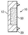
도 1 및 2a를 참조하면, 본 발명에 의한 고정 플레이트 시스템(10)의 일 구현예가 도시된다. 상기 고정 플레이트 시스템(10)은 제 1 말단(13)에서 반대측 제 2 말단(14)으로 세로축 A1을 따라 연장되는 연장 플레이트(12)를 포함한다. 플레이트(12)는 제 1 말단(13) 및 제 2 말단(14) 사이에서 연장되는 길이 L1을 가지고 약간 곡면으로 도시되어 요추 만곡과 실질적으로 일치된다. 플레이트(12)는 최상면(16) 및 대향하는 바닥면(18)을 가진다. 플레이트(12)는 최상면(16) 및 바닥면(18) 사이에 연장되는 높이 H1을 가진다. 도 2a에 도시된 플레이트(12)는 내측 뼈 대면 면(medial bone facing surface, 20) 및 반대측 외측 대면 면(lateral facing side, 22)을 가지며 이들 사이에 연장된 너비 또는 두께는 W1이다. 뼈 대면 면(20)에는 일련의 뼈 체결 못(26, 27 및 28)이 있어 뼈 표면을 최소한 부분적으로 관통하여 고정하여 뼈를 체결한다. 한 쌍의 파스너 수용 홀(44 및 46)은 플레이트(12)를 관통하여 연장된다.1 and 2A, one embodiment of a
도시된 구현예에 의한 고정 플레이트 시스템(10)은 뼈 대면 면(20) 내로 매몰된 보유채널(retention channel, 30)을 포함한다. 도 1에 도시된 바와 같이, 상기 보유채널(30)은 세로축 A1을 따라 보유채널의 제 1 말단 및 반대측 제 2 말단 사이에서 길이 L2로 연장된다. 도 2a에 도시된 바와 같이, 상기 보유채널(30)은 상부면(32), 하부면(34) 및 외측면(36)에 의해 한정된다. 상기 보유채널(30)은 두께 또는 깊이 W3을 가지며, 보유채널에 측면으로 인접한 플레이트 잔여부는 두께 또는 깊이 W2를 가진다. 도시된 구현예에서, 상기 보유채널의 깊이 W3은 플레이트(12)의 두께 W1의 절반보다 커서 W3은 W2 보다 크다. 상기 보유채널(30)은 상부면(32) 및 하부면(34) 사이에 연장되는 높이 H2를 가진다. 도시된 구현예에서, 높이 H2는 플레이트 높이 H1의 약 50%이다.The
보유채널(30) 내부에는 뼈 성장촉진물질(50)이 배치된다. 도시된 구현예에서, 뼈 성장촉진물질은 상기 보유채널(30)의 윤곽에 실질적으로 일치되도록 형성되었다. 뼈 성장촉진물질은 척주에서 천연 또는 이식된 뼈와 상호 작용하도록 제공되어 뼈 융합 또는 고정화 형성에 협력한다. 보유채널의 내측 개구를 횡단하도록 보유부재(40)를 배치함으로써 뼈 성장촉진물질은 플레이트(12)의 뼈 대면 면(20)에 고정된다. 도시된 구현예에서, 보유부재(40)는 보유채널(30)의 길이 L2에 걸쳐 상부벽(32)에서 하부벽(34)으로 연장된다. 상기 보유부재(40)는 메쉬(mesh) 구조체이며 신체의 체액 및 기타 세포들이 뼈 성장촉진물질과 접촉하도록 한다. 바람직한 양상에서, 상기 보유부재 메쉬(40)는 상기 메쉬를 횡단하여 뼈 성장이 촉진되기에 충분히 큰 구멍(pore) 크기를 가진다. 또한, 다른 양상에서, 메쉬(40)에서의 홀 크기는 전체 영역의 50% 이상이다. 이러한 구현예에서, 뼈 성장촉진물질은 최소한 부분적으로 유연(malleable)하며 뼈 성장촉진물질의 일부는 메쉬 개구를 통하여 연장되어 척추의 천연 또는 배치된 이식 뼈와 접촉할 수 있다. 이러한 구현예에서, 상기 메쉬는 최소한 부분적으로 뼈 성장촉진물질에 묻혀있다.The bone
하나의 구현예에서, 보유부재는 뼈가 형성될 때 뼈에 수용되기에 적합한 금속 또는 합성된 물질이다. 다른 구현예에서, 보유부재는 뼈가 성장할 때 시간 경과에 따라 재흡수되도록 형성된 재흡수성 물질이다. 또 다른 구현예에서, 보유부재는 작은 구멍 크기를 가지는 막이다. 하나의 양상에서, 상기 막은 50 마이크론 이상의 구멍 크기를 갖는다. 다른 양상에서 상기 구멍 크기는 50 마이크론 내지 1000 마이크론 범위이다. 또 다른 양상에서, 상기 막은 최소한 부분적으로 재흡수성이며 뼈가 형성되기 시작하면서 시간 경과에 따라 구멍이 확대된다. 또한, 막층(membrane layer)을 이용하여 뼈 성장촉진물질을 보유채널에 보유하는 구현예에서, 상기 물질은 실질적으로 액상 또는 슬러리 물질일 수 있어 플레이트에 미리 부착된 막을 통하여 보유채널로 바늘 또는 캐뉼러를 통하여 주입될 수 있다. 이러한 구현예에서, 상기 플레이트 및 막은 시술자에게 전달되기 전에 미리 조립될 수 있다. 또한, 상기 막은 뼈 성장물질을 원하는 회복 속도에 따라 몇 일, 주 또는 달 주기에 걸쳐 융합 부위에 인접한 환자의 시스템에 서서히 방출하도록 작용할 수 있다.In one embodiment, the retaining member is a metal or synthetic material suitable for being received in the bone when the bone is formed. In another embodiment, the retaining member is a resorbable material formed to reabsorb over time as the bone grows. In another embodiment, the retaining member is a membrane having a small pore size. In one aspect, the membrane has a pore size of at least 50 microns. In other aspects the pore size ranges from 50 microns to 1000 microns. In another aspect, the membrane is at least partially resorbable and the pores expand over time as bone begins to form. In addition, in embodiments in which bone growth promoting material is retained in the retention channel using a membrane layer, the material may be substantially liquid or slurry material such that the needle or cannula enters the retention channel through a membrane previously attached to the plate. It can be injected through. In such embodiments, the plate and membrane may be preassembled before delivery to the operator. The membrane can also act to release the bone growth material slowly into the patient's system adjacent to the fusion site over several days, weeks or months depending on the desired rate of recovery.
도 2b에 도시된 다른 구현예에서, 플레이트(12)는 도 1 및 2a의 구현예에 대하여 앞에서 기술된 바와 같이 보유채널(30)을 가지도록 제공된다. 도 2b의 구현예에서, 뼈 성장촉진물질(50)은 플레이트(12)의 내측 뼈 대면 면과 실질적으로 정렬되는 내측면을 가지도록 보유채널(30) 내에 배치된다. 이러한 구현예에서, 뼈 성장촉진물질(50)은 실질적으로 단단하며, 인체 이식에 적절한 의료급의 점착층(adhesive layer, 60)에 의해 보유채널 내에 유지된다. 적절한 접착제는 피브린 글루(fibrin glue) 또는 뼈 시멘트를 포함할 수 있으나, 다른 접착제에 대해 제한적이지 않다. 점착층(60)을 보유채널(30)의 측벽에 도시하였으나, 접착제는 이와 달리 또는 추가적으로 보유채널의 상부면 또는 하부면에 배치될 수 있는 것으로 의도된다.In another embodiment shown in FIG. 2B, the
도 2c에 도시된 또 다른 구현예에서, 도 1 및 2a에 대하여 앞에서 기술한 바와 같이 보유채널을 가지는 플레이트(12)가 도시된다. 도시된 구현예에서, 뼈 성장촉진물질(50)은 보유채널 내부에 맞게 형성되어 상기 물질(50)은 보유채널의 벽들과 직접 체결되어 제자리에 보유된다. 하나의 형상에서, 상기 뼈 성장촉진물질은 단단하고 보유채널 내부에 맞게 압력이 가해진다. 다른 형상에서, 상기 뼈 성장촉진물질은 실질적으로 유동성 물질이다. 보유채널은 물질로 채워지고 물질이 더욱 견고한 상태가 되도록 하거나 물질을 압착시켜 더욱 견고한 형태로 만든다.In another embodiment shown in FIG. 2C, a
플레이트(12)는 실질적으로 단단한 물질로 형성됨이 의도된다. 하나의 구현예에서 상기 플레이트는 의료급 스테인리스 강, 티타늄 또는 코발트 크롬과 같은 금속 물질로 형성된다. 다른 형태에서, 상기 플레이트는 플라스틱, 고분자, PEEK, 세라믹, 탄소 섬유 강화 고분자 등과 같은 합성 물질로 형성된다. 추가로, 하나의 구현예에서 상기 플레이트는 실질적으로 단단하게 제조되어 길이를 따른 모든 움직임을 방지한다. 또 다른 형태에서, 상기 플레이트는 최소한의 부분적 이동 또는 굴절(flexion)을 허용하도록 제조되어 뼈가 인접한 척추뼈 사이에서 움직이도록 한다. 이러한 물질들은 본 발명의 플레이트를 형성함에 있어서 다른 물질의 사용을 제한하지 않는다.The
본 명세서에서 사용되는, "뼈 성장촉진물질(bone growth promoting substance)"은 "생체적합물질 캐리어(biomaterial carrier)"와 함께 또는 없이, 제한적이지는 않지만 "생물학적 활성 성분(biologically active component)"을 포함한다.As used herein, "bone growth promoting substance" includes, but is not limited to, "biologically active component" with or without "biomaterial carrier". do.
"생물학적 활성 성분"은 제한적이지는 않지만, 자가 이식 뼈, 동종 이식 뼈, 이종 이식 뼈, 레트로바이러스 벡터 또는 플라스미드 바이러스 벡터를 가지는 자생 연골세포(autogenic chondrocyte); 레트로바이러스 벡터 또는 플라스미드 바이러스 벡터를 가지는 타생 연골세포(allogenic chondrocyte); 및 섬유모세모(fibroblast)를 포함한다. 두문자어 "LIM"은 LIM 도메인이 처음 기술되는 세 개의 유전자로부터 유래한다. LIM 도메인은 공통서열 CX2CX16-23HX2CX2CX2CX16-21CX2(C/H/D)을 가지는 50-60 아미노산에 의해 정의되며, 두개의 밀접하게 연관된 아연-결합 모듈을 함유하는 시스테인-풍부 모티프(motif)이다. LIM 광화(mineralizaition) 단백질은 제한적이지는 않지만 미국특허출원공개번호 제2003/0180266 A1에 개시된 것을 포함하며, 이는 참조로써 본 명세서에 편입된다. "성장인자"는 제한적이지는 않지만 전환성장인자 (TGF)-베타 1, TGF-베타 2, TGF-베타 3, 골형성성장인자 (bone morphogenetic protein, BMP)-2, BMP-3, BMP-4, BMP-6, BMP-7, BMP-9, 섬유모세포성장인자 (FGF), 성장 및 감별인자 (예를 들면, GDF 5) 혈소판유래성장인자 (PDGF), 인슐린유사성장인자 (ILGF); 인간내피세포성장인자 (ECGF); 표피성장인자 (EGF); 신경성장인자 (NGF); 및 혈관내피성장인자 (VEGF)를 포함한다. "안티-IL-1" 성분은 제한적이지는 않지만 미국특허출원공개번호 제2003/0220283호 및 제2005/0260159호에서 개시된 것을 포함하며, 이들 명세서는 전체로서 본원에 참조로써 편입된다. "줄기세포물질"은 제한적이지는 않지만, 역분화 줄기세포, 미분화 줄기세포, 및 중간엽 줄기세포를 포함한다. "줄기세포 물질"은 또한 제한적이지는 않지만 지방(lipo)-유래 줄기세포 물질을 포함할 수 있는 골수에서 추출된 줄기세포, 및 각각 참조로써 본원에 편입되는 미국공개번호 제2004/0193274호 및 제2005/0118228호에서 개시된 바와 같은 지방질(adipose)-유래 줄기세포 물질을 포함한다. "줄기세포 물질"은 또한 제한적이지는 않지만 각각 참조로써 본원에 편입되는 미국특허출원공개번호 제2003/0161816호, 제2004/0097867호 및 제2004/0106196호에 기재된 지방조직에서 유래한 줄기세포를 포함할 수 있다."Biologically active ingredients" include, but are not limited to, autogenic chondrocytes having autologous bone, allograft bone, xenograft bone, retroviral vectors or plasmid virus vectors; Allogenic chondrocytes with retroviral vectors or plasmid virus vectors; And fibroblasts. The acronym "LIM" is derived from the three genes in which the LIM domain is first described. The LIM domain is defined by 50-60 amino acids having the common sequence CX2CX16-23HX2CX2CX2CX16-21CX2 (C / H / D) and is a cysteine-rich motif containing two closely related zinc-binding modules. LIM mineralization proteins include, but are not limited to, those disclosed in US Patent Application Publication No. 2003/0180266 A1, which is incorporated herein by reference. "Growth factor" includes but is not limited to transforming growth factor (TGF) -beta 1, TGF-beta 2, TGF-beta 3, bone morphogenetic protein (BMP) -2, BMP-3, BMP-4 , BMP-6, BMP-7, BMP-9, fibroblast growth factor (FGF), growth and differential factors (eg GDF 5) platelet derived growth factor (PDGF), insulin-like growth factor (ILGF); Human endothelial cell growth factor (ECGF); Epidermal growth factor (EGF); Nerve growth factor (NGF); And vascular endothelial growth factor (VEGF). "Anti-IL-1" components include, but are not limited to, those disclosed in US Patent Application Publication Nos. 2003/0220283 and 2005/0260159, which are incorporated herein by reference in their entirety. "Stem cell material" includes, but is not limited to, dedifferentiated stem cells, undifferentiated stem cells, and mesenchymal stem cells. “Stem cell material” is also a stem cell derived from bone marrow that may include, but is not limited to, lipo-derived stem cell material, and US Publication Nos. 2004/0193274 and US, which are incorporated herein by reference, respectively. Fat-derived stem cell materials as disclosed in 2005/0118228. "Stem cell material" also includes, but is not limited to, stem cells derived from adipose tissue described in US Patent Application Publication Nos. 2003/0161816, 2004/0097867, and 2004/0106196, each of which is incorporated herein by reference. It may include.
"생물학적 활성 성분"은 또한 제한적이지는 않지만 BMP, LIM 광화 단백질, 또는 전체로 참조로써 본원에 편입되는 미국특허공개번호 제2003/0219423호 및 제2003/0228292호에 개시된 SMAD 단백질과 같은 단백질 또는 그의 변형을 인코딩하는 핵산을 포함하는 조작세포(engineered cell); 및 참조로써 본원에 편입되는 미국특허공개번호 제2004/0024081호에 개시되는 바와 같은 재조합 인간 골형성성장인자를 포함한다."Biologically active ingredients" are also, but are not limited to, proteins such as BMP, LIM mineralized proteins, or SMAD proteins disclosed in US Patent Publication Nos. 2003/0219423 and 2003/0228292, which are incorporated herein by reference in their entirety. Engineered cells comprising nucleic acids encoding modifications; And recombinant human osteogenic growth factor as disclosed in US Patent Publication No. 2004/0024081, which is incorporated herein by reference.
본 명세서에 사용되는 "생체적합물질 캐리어"는 제한적이지는 않지만 자가 이식뼈, 동종이식뼈, 이종이식뼈, 탈염 골 매트릭스 (demineralized bone matrix), 콜라겐, 젤라틴, 히알루론산, 피브린, 알부민, 케라틴, 실크, 엘라스틴, 칼슘 포스페이트 (예를 들면 히드록시 아파타이트 및 트리칼슘 포스페이트), 글리코사미노글리칸 (GAGs), 폴리에틸렌글리콜 (PEG), 폴리에틸렌옥사이드 (PEO), 폴리비닐알콜 (PVA) 히드로겔, 폴리비닐 피롤리돈 (PVP), PVA 및 PVP 공중합체, 기타 다당류, 혈소판 겔, 펩타이드, 카르복시메틸 셀룰로오스, 및 기타 변형 녹말 및 셀룰로오스의 단독 또는 조합을 포함한다. 콜라겐은 제한적이지는 않지만 자가, 동종, 이종 또는 인간-재조합 유래(origin)일 수 있는, 전체로 본원에 참조로써 편입되는 미국특허출원공개 제2004/0054414호 및 제2004/0228901호에 개시된 콜라겐-기초 물질과 같은 콜라겐-기초 물질을 포함한다.As used herein, "biocompatible carrier" includes, but is not limited to, autograft bone, allograft, xenograft, demineralized bone matrix, collagen, gelatin, hyaluronic acid, fibrin, albumin, keratin, Silk, elastin, calcium phosphate (e.g. hydroxy apatite and tricalcium phosphate), glycosaminoglycans (GAGs), polyethylene glycols (PEG), polyethylene oxides (PEO), polyvinyl alcohol (PVA) hydrogels, poly Vinyl pyrrolidone (PVP), PVA and PVP copolymers, other polysaccharides, platelet gels, peptides, carboxymethyl cellulose, and other modified starches and celluloses alone or in combination. Collagen is not limited, but can be autologous, allogeneic, heterologous, or human-originated, collagen-disclosed in US Patent Application Publication Nos. 2004/0054414 and 2004/0228901, which are incorporated herein by reference in their entirety. Collagen-based materials such as base materials.
예를 들면, 제한적이지는 않지만 뼈 성장촉진물질은 용액, 부유액(suspension), 유탁액(emulsion), 페이스트, 미립자 물질, 섬유 물질, 플러그, 고상, 다공성, 직조 또는 비-직조 물질, 또는 탈수 또는 재수화 상태의 형태를 가질 수 있다.For example, but not limited to, bone growth promoters may include solutions, suspensions, emulsions, pastes, particulate materials, fiber materials, plugs, solids, porous, woven or non-woven materials, or dehydration or It may take the form of a rehydration state.
도 3-5를 참조하여, 본 발명에 의한 고정화 시스템(10)의 사용을 설명한다. 도 3에, 플레이트(12), 뼈 성장촉진물질(50) 및 보유부재(40)를 도시한다. 하나의 양상에서, 이들 구성성분 모두는 단일 용도의 키트로 미리 조립되어 제공될 수 있다. 다른 양상에서, 상기 플레이트(12) 및 보유부재(40)가 키트로 제공된다. 상기 뼈 성장촉진물질은 제조원, 골 은행, 환자의 이식부위로부터 개별적으로 입수된다. 뼈 성장촉진물질(50)은 플레이트(12)의 보유채널과 정렬된다. 상기 물질(50)은 채널에 삽입된다. 보유부재(40)는 보유채널의 최소한의 일부에 걸쳐 연장되도록 상기 플레이트와 정렬되며 그에 따라 상기 플레이트에 부착된다. 하나의 형태에서, 보유부재(40)는 못(26, 27 및 28)에 걸쳐 연장되어 그 자리에 유지된다. 다른 대안 구현예에서, 메쉬는 보유채널 내부에 형성된 일부의 캐뉼러 리세스 (미도시)를 체결하는 하나 또는 그 이상의 보유클립 (미도시)을 포함한다. 또 다른 형태에서, 상기 보유부재(40)는 생체적합성 접착제에 의해 플레이트에 부착된다.3-5, the use of the
플레이트(12), 뼈 성장촉진물질(50) 및 보유부재(40)가 조립되면, 이들은 신체에 적용될 수 있다. 도 4 및 5에 도시된 사용에서, 본 발명에 의한 고정 플레이트 시스템(10)은 각각의 척추뼈들 V1, V2 및 V3의 가시돌기 SP1, SP2 및 SP3에 걸쳐 인체 척추에 적용된다. 비록 본 수술을 세 개의 척추뼈의 고정화에 대하여 기술하지만, 본 발명은 세 개의 척추뼈 보다 둘 또는 그 이상에 적용될 수도 있는 것이다. 또한, 가시돌기 융합을 설명의 목적으로 도시하였으나 앞서 설명된 바와 같이 형성된 플레이트는 모든 종류의 뼈 융합 수술에 단일 또는 기타 고정 플레이트와 함께 적용될 수 있는 것으로 의도된다. 도시된 구현예에서, 플레이트(12)는 도 3에 대하여 상기 기술한 바와 같이 준비된다. 또한, 가시돌기의 반대측 면에 상응하는 플레이트(12') 또한 본 발명에 따라 준비된다. 외과적 접근은 가시돌기 SP1, SP2 및 SP3의 양면을 따라 연장되도록 얻어진다. 플레이트(12)는 환자에게 삽입되고 보유채널이 뼈를 향하도록 배향되어 가시돌기에 인접하게 배치된다. 플레이트(12')는 환자에게 삽입되고 보유채널이 뼈를 향하도록 배향되어 플레이트(12)의 반대측 가시돌기에 인접하게 배치된다. 볼트(80)의 나사산 포스트(82)는 플레이트(12)의 개구(44) 및 플레이트(12')의 유사한 개구를 관통한다. 제 1 너트(84)는 포스트(82)에 조여져 플레이트(12')가 플레이트(12)를 향하도록 힘을 가하여 못이 뼈 내부로 연장하여 뼈와 체결될 것이다. 잠금 너트(86)가 나사산 포스트(82)로 전진하여 너트(84)가 느슨해지는 것을 방지한다. 유사한 방식으로, 볼트(90)의 나사산 포스트(92)가 플레이트(12)의 개구(46) 및 플레이트(12')의 상응하는 개구를 관통한다. 너트(94)는 나사산 포스트로 전진하여 플레이트들이 서로를 향하도록 하고, 잠금 너트가 전진하여 제 1 너트(94)를 그 자리에 잠근다.Once the
도시된 구현예에서, 파스너(80 및 90)는 애퍼추어(44 및 46)를 각각 관통하여 연장된다. 파스너(80)는 SP1 및 SP2 사이의 공간을 통하여 연장하고, 파스너(90)는 SP2 및 SP3 사이의 공간을 통하여 연장한다. 플레이트에서 홀이 이동되어 파스너가 뼈 융합이 의도되는 영역 외부로 연장될 수 있는 것이 의도된다. 예를 들면, 하나의 구현예에서, 플레이트는 융합되는 가시돌기를 초과하여 연장되는 길이를 가지고, 플레이트에서의 개구는 끼인 가시돌기 상부 및 하부에 배치된다. 파스너는 융합 구역 외부에서 개구를 관통하여 연장되어 플레이트를 뼈에 고정시키고 융합 과정을 방해하지 않는다. 다른 구현예에서, 플레이트는 파스너(80 및 90)를 위한 어떤 개구도 없는 실질적으로 속이 비지 않은 고형물이다. 이러한 구현예에서, 각각의 플레이트(12 및 12')의 외측면에 걸쳐 연장되는 한 쌍의 U-형상의 클립은 파스너(80 및 90)를 대신하여 뼈에 대하여 플레이트를 유지시킨다. 클립은 단일 스프링-바이어스 부재 또는 플레이트(12 및 12')가 서로를 향하도록 기계적으로 조절될 수 있는 클램프일 수 있다.In the illustrated embodiment,
비록 못(26, 27 및 28)은 상기 설명의 목적을 위하여 뼈 체결면으로써 플레이트(12)의 뼈 대면 면에 도시되었으나, 뼈 체결면은 널링(knurling), 거친 면, 소결 물질, 치상돌기, 그루브 또는 뼈를 체결하고 유지하기에 적합한 다른 표면 형상을 가질 수 있는 것으로 의도된다. 또한, 상기 표면은 뼈 내증식성 특징을 포함할 수 있어 뼈가 플레이트의 표면을 관통하도록 할 수 있다.Although the
비록 단지 몇몇의 바람직한 구현예만을 앞에서 상세하게 기술하였으나, 당해 기술 분야의 당업자들은 본 명세서의 새로운 교시 및 장점에서 실질적으로 벗어나지 않고 바람직한 구현예에서 많은 변형이 가능할 것이라는 것을 쉽게 이해할 것이다. 따라서 이러한 모든 변경 및 변형은 하기 특허청구범위에 정의된 바와 같이 본 발명의 범위 내에 포함되는 것으로 의도된다. 당해 기술 분야의 당업자들은 또한 이러한 변형 및 균등한 구조 또는 방법은 본 명세서의 정신 또는 범위를 벗어나지 않는다는 것을 인식할 것이고, 본 명세서의 정신 및 범위를 벗어남이 없이 다양한 변화, 대체 및 변경을 이룰 수 있을 것이다.Although only a few preferred embodiments have been described in detail above, those skilled in the art will readily appreciate that many modifications may be made in the preferred embodiments without departing substantially from the novel teachings and advantages herein. Accordingly, all such changes and modifications are intended to be included within the scope of the invention as defined in the following claims. Those skilled in the art will also recognize that such modifications and equivalent structures or methods do not depart from the spirit or scope of the present disclosure, and that various changes, substitutions and changes may be made without departing from the spirit and scope of the present disclosure. will be.
"수평", "수직", "최상부", "내부", "외부", "바닥", "좌", "우", "전방", "후방", "상부", "하부", "내측", "외측", "위" 및 "아래"와 같은 모든 공간적 참조들은 단지 예시적 목적이고 본 명세서의 범위 내에서 변경될 수 있는 것으로 이해된다. 특허청구범위에서, 수단-기능 청구항들은 언급된 기능을 수행하도록 본 명세서에 기재된 구성들 및 구조적 균등물뿐만 아니라 균등한 구성들을 포함하는 것으로 의도된다."Horizontal", "vertical", "top", "inside", "outside", "bottom", "left", "right", "front", "rear", "top", "bottom", "inside It is understood that all spatial references, such as "," outer "," above "and" below "are for illustrative purposes only and may be modified within the scope of this specification. In the claims, the means-function claims are intended to include equivalent constructions as well as the structural and structural equivalents described herein to perform the stated function.
도 1은 본 발명의 하나의 양상에 의한 고정 플레이트 시스템의 측면도이다.1 is a side view of a fixed plate system according to one aspect of the present invention.
도 2a는 도 1의 선2A-2A을 따라 잘린 단면도이다.2A is a cross-sectional view taken along line 2A-2A of FIG. 1.
도 2b 및 2c는 도 1의 고정 플레이트와 유사한 다른 구현예들의 단면도이다.2B and 2C are cross-sectional views of other embodiments similar to the fixing plate of FIG. 1.
도 3은 도 1에 도시된 고정 플레이트 시스템의 부분 분해도이다.3 is a partial exploded view of the fixed plate system shown in FIG. 1.
도 4는 본 발명의 다른 양상에 의한 고정 플레이트를 가지는 척추의 부분 사시측면도이다.4 is a partial perspective side view of the spine having a fixation plate according to another aspect of the present invention.
도 5는 도 4의 고정화 시스템을 가지는 척추의 배면도이다.5 is a rear view of the spine having the immobilization system of FIG. 4.
Claims (15)
Translated fromKoreanApplications Claiming Priority (2)
| Application Number | Priority Date | Filing Date | Title |
|---|---|---|---|
| US11/404,305 | 2006-04-14 | ||
| US11/404,305US7806911B2 (en) | 2006-04-14 | 2006-04-14 | Fixation plate and method of use |
Publications (1)
| Publication Number | Publication Date |
|---|---|
| KR20090009868Atrue KR20090009868A (en) | 2009-01-23 |
Family
ID=38577649
Family Applications (1)
| Application Number | Title | Priority Date | Filing Date |
|---|---|---|---|
| KR1020087027946AAbandonedKR20090009868A (en) | 2006-04-14 | 2007-03-30 | Fixing plate having bone growth promoting material and method of use |
Country Status (6)
| Country | Link |
|---|---|
| US (1) | US7806911B2 (en) |
| EP (1) | EP2010078A2 (en) |
| JP (1) | JP2009533167A (en) |
| KR (1) | KR20090009868A (en) |
| CN (1) | CN101437461B (en) |
| WO (1) | WO2007121070A2 (en) |
Cited By (4)
| Publication number | Priority date | Publication date | Assignee | Title |
|---|---|---|---|---|
| KR101697252B1 (en)* | 2015-08-04 | 2017-01-18 | 전북대학교산학협력단 | Fixing plate for bone fracture |
| KR101896955B1 (en) | 2018-01-10 | 2018-09-10 | 롯데건설 주식회사 | Supporting device for safety rope and method for constructing the same |
| KR101896956B1 (en) | 2018-01-10 | 2018-09-10 | 롯데건설 주식회사 | Supporting device for safety rope and method for constructing the same |
| KR20200021305A (en) | 2018-08-20 | 2020-02-28 | 롯데건설 주식회사 | Fixing unit for safety rope, safety rope supporting device having the same and method for constructing safety rope supporting device |
Families Citing this family (127)
| Publication number | Priority date | Publication date | Assignee | Title |
|---|---|---|---|---|
| US7846183B2 (en) | 2004-02-06 | 2010-12-07 | Spinal Elements, Inc. | Vertebral facet joint prosthesis and method of fixation |
| US9504583B2 (en) | 2004-06-10 | 2016-11-29 | Spinal Elements, Inc. | Implant and method for facet immobilization |
| US8277488B2 (en) | 2004-10-20 | 2012-10-02 | Vertiflex, Inc. | Interspinous spacer |
| US8167944B2 (en) | 2004-10-20 | 2012-05-01 | The Board Of Trustees Of The Leland Stanford Junior University | Systems and methods for posterior dynamic stabilization of the spine |
| US8152837B2 (en) | 2004-10-20 | 2012-04-10 | The Board Of Trustees Of The Leland Stanford Junior University | Systems and methods for posterior dynamic stabilization of the spine |
| US9119680B2 (en) | 2004-10-20 | 2015-09-01 | Vertiflex, Inc. | Interspinous spacer |
| US8123807B2 (en) | 2004-10-20 | 2012-02-28 | Vertiflex, Inc. | Systems and methods for posterior dynamic stabilization of the spine |
| US8012207B2 (en) | 2004-10-20 | 2011-09-06 | Vertiflex, Inc. | Systems and methods for posterior dynamic stabilization of the spine |
| US9161783B2 (en) | 2004-10-20 | 2015-10-20 | Vertiflex, Inc. | Interspinous spacer |
| US7763074B2 (en) | 2004-10-20 | 2010-07-27 | The Board Of Trustees Of The Leland Stanford Junior University | Systems and methods for posterior dynamic stabilization of the spine |
| US8128662B2 (en) | 2004-10-20 | 2012-03-06 | Vertiflex, Inc. | Minimally invasive tooling for delivery of interspinous spacer |
| US8273108B2 (en) | 2004-10-20 | 2012-09-25 | Vertiflex, Inc. | Interspinous spacer |
| US8317864B2 (en) | 2004-10-20 | 2012-11-27 | The Board Of Trustees Of The Leland Stanford Junior University | Systems and methods for posterior dynamic stabilization of the spine |
| US8425559B2 (en) | 2004-10-20 | 2013-04-23 | Vertiflex, Inc. | Systems and methods for posterior dynamic stabilization of the spine |
| US8613747B2 (en) | 2004-10-20 | 2013-12-24 | Vertiflex, Inc. | Spacer insertion instrument |
| US9023084B2 (en) | 2004-10-20 | 2015-05-05 | The Board Of Trustees Of The Leland Stanford Junior University | Systems and methods for stabilizing the motion or adjusting the position of the spine |
| US8123782B2 (en) | 2004-10-20 | 2012-02-28 | Vertiflex, Inc. | Interspinous spacer |
| US8945183B2 (en) | 2004-10-20 | 2015-02-03 | Vertiflex, Inc. | Interspinous process spacer instrument system with deployment indicator |
| US8409282B2 (en) | 2004-10-20 | 2013-04-02 | Vertiflex, Inc. | Systems and methods for posterior dynamic stabilization of the spine |
| US9055981B2 (en) | 2004-10-25 | 2015-06-16 | Lanx, Inc. | Spinal implants and methods |
| US8241330B2 (en) | 2007-01-11 | 2012-08-14 | Lanx, Inc. | Spinous process implants and associated methods |
| WO2006058221A2 (en) | 2004-11-24 | 2006-06-01 | Abdou Samy M | Devices and methods for inter-vertebral orthopedic device placement |
| EP2219538B1 (en) | 2004-12-06 | 2022-07-06 | Vertiflex, Inc. | Spacer insertion instrument |
| US9907580B2 (en)* | 2005-11-22 | 2018-03-06 | Bryson Medical Technology Llc | Adjustable spinous process spacer device and method of treating spinal disorders |
| US8845726B2 (en) | 2006-10-18 | 2014-09-30 | Vertiflex, Inc. | Dilator |
| US9247968B2 (en) | 2007-01-11 | 2016-02-02 | Lanx, Inc. | Spinous process implants and associated methods |
| US9265532B2 (en) | 2007-01-11 | 2016-02-23 | Lanx, Inc. | Interspinous implants and methods |
| US8568453B2 (en)* | 2007-01-29 | 2013-10-29 | Samy Abdou | Spinal stabilization systems and methods of use |
| US8992533B2 (en) | 2007-02-22 | 2015-03-31 | Spinal Elements, Inc. | Vertebral facet joint drill and method of use |
| EP2813190B1 (en) | 2007-02-22 | 2017-04-26 | Spinal Elements, Inc. | Vertebral facet joint drill |
| US7842074B2 (en) | 2007-02-26 | 2010-11-30 | Abdou M Samy | Spinal stabilization systems and methods of use |
| WO2008124831A2 (en)* | 2007-04-10 | 2008-10-16 | Lee David M D | Adjustable spine distraction implant |
| AU2008241447B2 (en) | 2007-04-16 | 2014-03-27 | Vertiflex, Inc. | Interspinous spacer |
| US8257395B2 (en)* | 2007-09-21 | 2012-09-04 | Jmea Corporation | Spinal fixation with selectively applied bone growth promoting agent |
| US8241357B2 (en) | 2007-04-25 | 2012-08-14 | Jmea Corporation | Prosthesis with a selectively applied bone growth promoting agent |
| US20090048675A1 (en)* | 2007-04-25 | 2009-02-19 | Bhatnagar Mohit K | Spinal Fusion Implants with Selectively Applied Bone Growth Promoting Agent |
| US7922767B2 (en) | 2007-07-07 | 2011-04-12 | Jmea Corporation | Disk fusion implant |
| US20090024147A1 (en)* | 2007-07-18 | 2009-01-22 | Ralph James D | Implantable mesh for musculoskeletal trauma, orthopedic reconstruction and soft tissue repair |
| US20090171394A1 (en)* | 2007-12-18 | 2009-07-02 | Abdou M S | Devices And Methods For The Treatment Of Facet Joint Disease |
| WO2009086402A1 (en)* | 2007-12-28 | 2009-07-09 | Pronto Products, Llc | Rib bone tissue clamp |
| US8940019B2 (en) | 2007-12-28 | 2015-01-27 | Osteomed Spine, Inc. | Bone tissue fixation device and method |
| AU2009206098B2 (en) | 2008-01-15 | 2014-10-30 | Vertiflex, Inc. | Interspinous spacer |
| US8343190B1 (en) | 2008-03-26 | 2013-01-01 | Nuvasive, Inc. | Systems and methods for spinous process fixation |
| US9301788B2 (en) | 2008-04-10 | 2016-04-05 | Life Spine, Inc. | Adjustable spine distraction implant |
| WO2010025405A1 (en)* | 2008-08-29 | 2010-03-04 | Life Spine, Inc. | Single-sided dynamic spine plates |
| WO2010096824A1 (en)* | 2009-02-23 | 2010-08-26 | Bartee Barry K | Reinforced ptfe medical barrier |
| WO2010104935A1 (en)* | 2009-03-10 | 2010-09-16 | Simpirica Spine, Inc. | Surgical tether apparatus and methods of use |
| US8303629B1 (en)* | 2009-03-19 | 2012-11-06 | Abdou M Samy | Spinous process fusion and orthopedic implants and methods |
| US9095380B2 (en) | 2009-03-31 | 2015-08-04 | Hamid R. Mir | Spinous process cross-link |
| US9414864B2 (en) | 2009-04-15 | 2016-08-16 | Warsaw Orthopedic, Inc. | Anterior spinal plate with preformed drug-eluting device affixed thereto |
| US9078712B2 (en)* | 2009-04-15 | 2015-07-14 | Warsaw Orthopedic, Inc. | Preformed drug-eluting device to be affixed to an anterior spinal plate |
| US9439685B2 (en) | 2009-05-12 | 2016-09-13 | Bullard Spine, Llc | Multi-layer osteoinductive, osteogenic, and osteoconductive carrier |
| US8636772B2 (en) | 2009-06-23 | 2014-01-28 | Osteomed Llc | Bone plates, screws, and instruments |
| EP2445428A2 (en) | 2009-06-23 | 2012-05-02 | Osteomed Spine, Inc. | Bone tissue clamp |
| US8721686B2 (en) | 2009-06-23 | 2014-05-13 | Osteomed Llc | Spinous process fusion implants and insertion, compression, and locking instrumentation |
| DK2453939T3 (en)* | 2009-07-16 | 2014-02-03 | Anatoli D Dosta | bone implants |
| BR112012003050A2 (en) | 2009-08-10 | 2019-09-24 | Osteomed Llc | bone plate assembly, bone surface attachment plate, cushion and bone plate |
| US8764806B2 (en) | 2009-12-07 | 2014-07-01 | Samy Abdou | Devices and methods for minimally invasive spinal stabilization and instrumentation |
| US8740948B2 (en) | 2009-12-15 | 2014-06-03 | Vertiflex, Inc. | Spinal spacer for cervical and other vertebra, and associated systems and methods |
| US8444699B2 (en)* | 2010-02-18 | 2013-05-21 | Biomet Manufacturing Corp. | Method and apparatus for augmenting bone defects |
| US8690918B1 (en)* | 2010-12-03 | 2014-04-08 | Onike Technologies | Spinous process fusion reduction plate for lumbar spine |
| US9034048B2 (en)* | 2011-01-26 | 2015-05-19 | John A. Choren | Orthopaedic implants and methods of forming implant structures |
| US9510940B2 (en)* | 2011-02-17 | 2016-12-06 | Ethicon, Inc. | Bioabsorbable multilayer nasal valve spreader graft |
| US9271765B2 (en) | 2011-02-24 | 2016-03-01 | Spinal Elements, Inc. | Vertebral facet joint fusion implant and method for fusion |
| USD724733S1 (en) | 2011-02-24 | 2015-03-17 | Spinal Elements, Inc. | Interbody bone implant |
| US8740949B2 (en) | 2011-02-24 | 2014-06-03 | Spinal Elements, Inc. | Methods and apparatus for stabilizing bone |
| RU2605147C2 (en) | 2011-04-01 | 2016-12-20 | Зинтес Гмбх | System for posterior spinal fixation with plate |
| JP6044961B2 (en)* | 2011-06-20 | 2016-12-14 | 国立大学法人秋田大学 | Spine brake |
| USD757943S1 (en) | 2011-07-14 | 2016-05-31 | Nuvasive, Inc. | Spinous process plate |
| US8882805B1 (en) | 2011-08-02 | 2014-11-11 | Lawrence Maccree | Spinal fixation system |
| US8845728B1 (en) | 2011-09-23 | 2014-09-30 | Samy Abdou | Spinal fixation devices and methods of use |
| US11812923B2 (en) | 2011-10-07 | 2023-11-14 | Alan Villavicencio | Spinal fixation device |
| US8657855B2 (en)* | 2011-10-17 | 2014-02-25 | Warsaw Orthopedic, Inc. | Spinal fixation implant for mounting to spinous processes and related method |
| USD739935S1 (en) | 2011-10-26 | 2015-09-29 | Spinal Elements, Inc. | Interbody bone implant |
| JP6282596B2 (en) | 2011-12-07 | 2018-02-21 | スミス アンド ネフュー インコーポレイテッド | Orthopedic implant augment |
| US9107718B2 (en)* | 2012-01-10 | 2015-08-18 | Biomet Manufacturing, Llc | Bone plate |
| US20130226240A1 (en) | 2012-02-22 | 2013-08-29 | Samy Abdou | Spinous process fixation devices and methods of use |
| US10448977B1 (en) | 2012-03-31 | 2019-10-22 | Ali H. MESIWALA | Interspinous device and related methods |
| US8771277B2 (en) | 2012-05-08 | 2014-07-08 | Globus Medical, Inc | Device and a method for implanting a spinous process fixation device |
| WO2013167731A1 (en)* | 2012-05-11 | 2013-11-14 | Aesculap Ag | Implant for stabilizing spinous processes |
| US9198767B2 (en) | 2012-08-28 | 2015-12-01 | Samy Abdou | Devices and methods for spinal stabilization and instrumentation |
| US9320617B2 (en) | 2012-10-22 | 2016-04-26 | Cogent Spine, LLC | Devices and methods for spinal stabilization and instrumentation |
| US9198697B2 (en) | 2013-03-13 | 2015-12-01 | Globus Medical, Inc. | Spinous process fixation system and methods thereof |
| US9486251B2 (en) | 2012-12-31 | 2016-11-08 | Globus Medical, Inc. | Spinous process fixation system and methods thereof |
| US9011493B2 (en) | 2012-12-31 | 2015-04-21 | Globus Medical, Inc. | Spinous process fixation system and methods thereof |
| US20140257390A1 (en)* | 2013-03-07 | 2014-09-11 | Kenneth M Little | Osseointegrative Spinal Fixation Implants |
| US9421044B2 (en) | 2013-03-14 | 2016-08-23 | Spinal Elements, Inc. | Apparatus for bone stabilization and distraction and methods of use |
| USD765853S1 (en) | 2013-03-14 | 2016-09-06 | Spinal Elements, Inc. | Flexible elongate member with a portion configured to receive a bone anchor |
| US9820784B2 (en) | 2013-03-14 | 2017-11-21 | Spinal Elements, Inc. | Apparatus for spinal fixation and methods of use |
| US9675303B2 (en) | 2013-03-15 | 2017-06-13 | Vertiflex, Inc. | Visualization systems, instruments and methods of using the same in spinal decompression procedures |
| TWI572319B (en)* | 2013-03-27 | 2017-03-01 | 梓源生技有限公司 | Pedicle screw system |
| JP2016517783A (en)* | 2013-05-15 | 2016-06-20 | ネッツリ,フーベルト・ピウス | Implant for fracture stabilization outside the cortex |
| JP2015000208A (en)* | 2013-06-17 | 2015-01-05 | 株式会社ジーシー | Fracture part treatment member |
| US9839450B2 (en)* | 2013-09-27 | 2017-12-12 | Spinal Elements, Inc. | Device and method for reinforcement of a facet |
| US9456855B2 (en) | 2013-09-27 | 2016-10-04 | Spinal Elements, Inc. | Method of placing an implant between bone portions |
| AU2015256024B2 (en) | 2014-05-07 | 2020-03-05 | Vertiflex, Inc. | Spinal nerve decompression systems, dilation systems, and methods of using the same |
| US20170189159A1 (en) | 2014-06-24 | 2017-07-06 | Osteogenics Biomedical, Inc. | Perforated membrane for guided bone and tissue regeneration |
| US9763706B2 (en)* | 2014-08-14 | 2017-09-19 | FloSpine, LLC | Interspinous fusion device |
| US11478275B2 (en) | 2014-09-17 | 2022-10-25 | Spinal Elements, Inc. | Flexible fastening band connector |
| US9901457B2 (en) | 2014-10-16 | 2018-02-27 | Jmea Corporation | Coiling implantable prostheses |
| CA2977625A1 (en) | 2014-12-29 | 2016-07-07 | Bioventus, Llc | Systems and methods for improved delivery of osteoinductive molecules in bone repair |
| US20160213405A1 (en)* | 2015-01-27 | 2016-07-28 | K2M, Inc. | Vertebral plate systems and methods of use |
| AU2016212009C1 (en) | 2015-01-27 | 2021-02-25 | Spinal Elements, Inc. | Facet joint implant |
| US10028841B2 (en) | 2015-01-27 | 2018-07-24 | K2M, Inc. | Interbody spacer |
| US10952856B2 (en)* | 2015-04-15 | 2021-03-23 | FreeseTEC Corporation | Spinal fusion containment system |
| US10857003B1 (en) | 2015-10-14 | 2020-12-08 | Samy Abdou | Devices and methods for vertebral stabilization |
| US10335207B2 (en) | 2015-12-29 | 2019-07-02 | Nuvasive, Inc. | Spinous process plate fixation assembly |
| US20170290645A1 (en)* | 2016-04-12 | 2017-10-12 | EdMiDent, LLC | Fixation system |
| WO2018009671A1 (en) | 2016-07-07 | 2018-01-11 | Stern Mark S | Spinous laminar clamp assembly |
| US10744000B1 (en) | 2016-10-25 | 2020-08-18 | Samy Abdou | Devices and methods for vertebral bone realignment |
| US10973648B1 (en) | 2016-10-25 | 2021-04-13 | Samy Abdou | Devices and methods for vertebral bone realignment |
| WO2019051260A1 (en) | 2017-09-08 | 2019-03-14 | Pioneer Surgical Technology, Inc. | Intervertebral implants, instruments, and methods |
| CN109044518A (en)* | 2018-09-07 | 2018-12-21 | 张煜辉 | Resistance to plucking goes out Medical screw |
| US11179248B2 (en) | 2018-10-02 | 2021-11-23 | Samy Abdou | Devices and methods for spinal implantation |
| US11660373B2 (en)* | 2019-02-09 | 2023-05-30 | Tetrous, Inc. | Demineralized bone fiber implant compositions and methods for rotator cuff and ACL repair |
| CN109730813A (en)* | 2019-03-19 | 2019-05-10 | 卿培东 | A kind of Invasive lumbar fusion device |
| US11457959B2 (en) | 2019-05-22 | 2022-10-04 | Spinal Elements, Inc. | Bone tie and bone tie inserter |
| BR112021022695A2 (en) | 2019-05-22 | 2021-12-28 | Spinal Elements Inc | Bone tethering and bone tethering inserter |
| CN110141349A (en)* | 2019-05-29 | 2019-08-20 | 中国人民解放军第二军医大学第二附属医院 | Spinous process lamina replantation internal fixation device |
| US11389209B2 (en) | 2019-07-19 | 2022-07-19 | Medos International Sarl | Surgical plating systems, devices, and related methods |
| WO2021163313A1 (en) | 2020-02-14 | 2021-08-19 | Spinal Elements, Inc. | Bone tie methods |
| CN112603515B (en)* | 2020-12-29 | 2022-02-18 | 北京爱康宜诚医疗器材有限公司 | Combined bone-knitting device |
| CN114010296A (en)* | 2021-11-08 | 2022-02-08 | 北京市春立正达医疗器械股份有限公司 | Locking plate for distal tibia |
| US12369952B2 (en) | 2021-12-10 | 2025-07-29 | Spinal Elements, Inc. | Bone tie and portal |
| WO2023158581A1 (en) | 2022-02-15 | 2023-08-24 | Boston Scientific Neuromodulation Corporation | Interspinous spacer and systems utilizing the interspinous spacer |
| US12433646B2 (en) | 2023-02-21 | 2025-10-07 | Boston Scientific Neuromodulation Corporation | Interspinous spacer with actuator locking arrangements and methods and systems |
| US12390340B2 (en) | 2023-03-15 | 2025-08-19 | Boston Scientific Neuromodulation Corporation | Interspinous spacer with a range of deployment positions and methods and systems |
Family Cites Families (11)
| Publication number | Priority date | Publication date | Assignee | Title |
|---|---|---|---|---|
| US3648691A (en)* | 1970-02-24 | 1972-03-14 | Univ Colorado State Res Found | Method of applying vertebral appliance |
| US6978166B2 (en)* | 1994-10-07 | 2005-12-20 | Saint Louis University | System for use in displaying images of a body part |
| US6312431B1 (en)* | 2000-04-24 | 2001-11-06 | Wilson T. Asfora | Vertebrae linking system |
| US6692498B1 (en) | 2000-11-27 | 2004-02-17 | Linvatec Corporation | Bioabsorbable, osteopromoting fixation plate |
| US6364883B1 (en)* | 2001-02-23 | 2002-04-02 | Albert N. Santilli | Spinous process clamp for spinal fusion and method of operation |
| WO2003007829A1 (en)* | 2001-07-20 | 2003-01-30 | Spinal Concepts, Inc. | Spinal stabilization system and method |
| US6635087B2 (en)* | 2001-08-29 | 2003-10-21 | Christopher M. Angelucci | Laminoplasty implants and methods of use |
| US8105366B2 (en)* | 2002-05-30 | 2012-01-31 | Warsaw Orthopedic, Inc. | Laminoplasty plate with flanges |
| NL1021137C2 (en)* | 2002-07-23 | 2004-01-27 | Fondel Finance B V | Support element for attachment to bone. |
| US20060106381A1 (en)* | 2004-11-18 | 2006-05-18 | Ferree Bret A | Methods and apparatus for treating spinal stenosis |
| WO2006116853A1 (en) | 2005-05-02 | 2006-11-09 | Kinetic Spine Technologies Inc. | Spinal stabilisation implant |
- 2006
- 2006-04-14USUS11/404,305patent/US7806911B2/enactiveActive
- 2007
- 2007-03-30EPEP07759782Apatent/EP2010078A2/ennot_activeWithdrawn
- 2007-03-30CNCN2007800141116Apatent/CN101437461B/ennot_activeExpired - Fee Related
- 2007-03-30WOPCT/US2007/065591patent/WO2007121070A2/enactiveApplication Filing
- 2007-03-30KRKR1020087027946Apatent/KR20090009868A/ennot_activeAbandoned
- 2007-03-30JPJP2009505533Apatent/JP2009533167A/ennot_activeWithdrawn
Cited By (4)
| Publication number | Priority date | Publication date | Assignee | Title |
|---|---|---|---|---|
| KR101697252B1 (en)* | 2015-08-04 | 2017-01-18 | 전북대학교산학협력단 | Fixing plate for bone fracture |
| KR101896955B1 (en) | 2018-01-10 | 2018-09-10 | 롯데건설 주식회사 | Supporting device for safety rope and method for constructing the same |
| KR101896956B1 (en) | 2018-01-10 | 2018-09-10 | 롯데건설 주식회사 | Supporting device for safety rope and method for constructing the same |
| KR20200021305A (en) | 2018-08-20 | 2020-02-28 | 롯데건설 주식회사 | Fixing unit for safety rope, safety rope supporting device having the same and method for constructing safety rope supporting device |
Also Published As
| Publication number | Publication date |
|---|---|
| WO2007121070A2 (en) | 2007-10-25 |
| US7806911B2 (en) | 2010-10-05 |
| WO2007121070A3 (en) | 2008-03-13 |
| CN101437461A (en) | 2009-05-20 |
| WO2007121070B1 (en) | 2008-05-08 |
| JP2009533167A (en) | 2009-09-17 |
| EP2010078A2 (en) | 2009-01-07 |
| US20070270812A1 (en) | 2007-11-22 |
| CN101437461B (en) | 2012-05-30 |
Similar Documents
| Publication | Publication Date | Title |
|---|---|---|
| KR20090009868A (en) | Fixing plate having bone growth promoting material and method of use | |
| US10342662B2 (en) | Aspirating implants and method of bony regeneration | |
| Antoniac | Handbook of bioceramics and biocomposites | |
| EP1883377B1 (en) | Synthetic loadbearing collagen-mineral composites for spinal implants | |
| US9220608B2 (en) | Facet joint implant device | |
| US10182921B2 (en) | Interbody device with opening to allow packing graft and other biologics | |
| US8163018B2 (en) | Treatment of the vertebral column | |
| EP2055267B1 (en) | Radiolucent bone graft | |
| US9724205B2 (en) | Biodegradable implant for intertransverse process fusion | |
| US6761739B2 (en) | Cortical and cancellous allograft spacer | |
| US9295561B2 (en) | Interbody spacer | |
| US20070213717A1 (en) | Biological fusion in the vertebral column | |
| US20070213718A1 (en) | Treatment of the vertebral column | |
| US20070227547A1 (en) | Treatment of the vertebral column | |
| JP2003505205A (en) | Cartilage or bone matrix as a nucleic acid delivery vehicle | |
| US20080161923A1 (en) | Intervertebral Motion Disc Having A Resorbable Keel |
Legal Events
| Date | Code | Title | Description |
|---|---|---|---|
| PA0105 | International application | Patent event date:20081114 Patent event code:PA01051R01D Comment text:International Patent Application | |
| PG1501 | Laying open of application | ||
| A201 | Request for examination | ||
| PA0201 | Request for examination | Patent event code:PA02012R01D Patent event date:20090313 Comment text:Request for Examination of Application | |
| E902 | Notification of reason for refusal | ||
| PE0902 | Notice of grounds for rejection | Comment text:Notification of reason for refusal Patent event date:20110314 Patent event code:PE09021S01D | |
| E701 | Decision to grant or registration of patent right | ||
| PE0701 | Decision of registration | Patent event code:PE07011S01D Comment text:Decision to Grant Registration Patent event date:20111130 | |
| NORF | Unpaid initial registration fee | ||
| PC1904 | Unpaid initial registration fee |