KR20090009436A - LED backlight - Google Patents
LED backlightDownload PDFInfo
- Publication number
- KR20090009436A KR20090009436AKR1020070072704AKR20070072704AKR20090009436AKR 20090009436 AKR20090009436 AKR 20090009436AKR 1020070072704 AKR1020070072704 AKR 1020070072704AKR 20070072704 AKR20070072704 AKR 20070072704AKR 20090009436 AKR20090009436 AKR 20090009436A
- Authority
- KR
- South Korea
- Prior art keywords
- led
- driving
- signal
- selection
- multiplexer
- Prior art date
- Legal status (The legal status is an assumption and is not a legal conclusion. Google has not performed a legal analysis and makes no representation as to the accuracy of the status listed.)
- Withdrawn
Links
- 238000000034methodMethods0.000claimsdescription3
- 239000003086colorantSubstances0.000claimsdescription2
- 239000011521glassSubstances0.000description9
- 239000004973liquid crystal related substanceSubstances0.000description6
- 238000010586diagramMethods0.000description4
- 230000003287optical effectEffects0.000description3
- 239000000758substrateSubstances0.000description2
- 239000010409thin filmSubstances0.000description2
- 230000001678irradiating effectEffects0.000description1
- 238000012986modificationMethods0.000description1
- 230000004048modificationEffects0.000description1
- 238000002834transmittanceMethods0.000description1
Images


Classifications
- G—PHYSICS
- G09—EDUCATION; CRYPTOGRAPHY; DISPLAY; ADVERTISING; SEALS
- G09G—ARRANGEMENTS OR CIRCUITS FOR CONTROL OF INDICATING DEVICES USING STATIC MEANS TO PRESENT VARIABLE INFORMATION
- G09G3/00—Control arrangements or circuits, of interest only in connection with visual indicators other than cathode-ray tubes
- G09G3/20—Control arrangements or circuits, of interest only in connection with visual indicators other than cathode-ray tubes for presentation of an assembly of a number of characters, e.g. a page, by composing the assembly by combination of individual elements arranged in a matrix no fixed position being assigned to or needed to be assigned to the individual characters or partial characters
- G09G3/34—Control arrangements or circuits, of interest only in connection with visual indicators other than cathode-ray tubes for presentation of an assembly of a number of characters, e.g. a page, by composing the assembly by combination of individual elements arranged in a matrix no fixed position being assigned to or needed to be assigned to the individual characters or partial characters by control of light from an independent source
- G09G3/3406—Control of illumination source
- G09G3/3413—Details of control of colour illumination sources
- G—PHYSICS
- G02—OPTICS
- G02F—OPTICAL DEVICES OR ARRANGEMENTS FOR THE CONTROL OF LIGHT BY MODIFICATION OF THE OPTICAL PROPERTIES OF THE MEDIA OF THE ELEMENTS INVOLVED THEREIN; NON-LINEAR OPTICS; FREQUENCY-CHANGING OF LIGHT; OPTICAL LOGIC ELEMENTS; OPTICAL ANALOGUE/DIGITAL CONVERTERS
- G02F1/00—Devices or arrangements for the control of the intensity, colour, phase, polarisation or direction of light arriving from an independent light source, e.g. switching, gating or modulating; Non-linear optics
- G02F1/01—Devices or arrangements for the control of the intensity, colour, phase, polarisation or direction of light arriving from an independent light source, e.g. switching, gating or modulating; Non-linear optics for the control of the intensity, phase, polarisation or colour
- G02F1/13—Devices or arrangements for the control of the intensity, colour, phase, polarisation or direction of light arriving from an independent light source, e.g. switching, gating or modulating; Non-linear optics for the control of the intensity, phase, polarisation or colour based on liquid crystals, e.g. single liquid crystal display cells
- G02F1/133—Constructional arrangements; Operation of liquid crystal cells; Circuit arrangements
- G—PHYSICS
- G09—EDUCATION; CRYPTOGRAPHY; DISPLAY; ADVERTISING; SEALS
- G09G—ARRANGEMENTS OR CIRCUITS FOR CONTROL OF INDICATING DEVICES USING STATIC MEANS TO PRESENT VARIABLE INFORMATION
- G09G2310/00—Command of the display device
- G09G2310/02—Addressing, scanning or driving the display screen or processing steps related thereto
- G09G2310/0235—Field-sequential colour display
Landscapes
- Physics & Mathematics (AREA)
- Engineering & Computer Science (AREA)
- General Physics & Mathematics (AREA)
- Theoretical Computer Science (AREA)
- Computer Hardware Design (AREA)
- Nonlinear Science (AREA)
- Crystallography & Structural Chemistry (AREA)
- Optics & Photonics (AREA)
- Chemical & Material Sciences (AREA)
- Mathematical Physics (AREA)
- Liquid Crystal Display Device Control (AREA)
- Control Of Indicators Other Than Cathode Ray Tubes (AREA)
- Liquid Crystal (AREA)
Abstract
Description
Translated fromKorean도 1은 상기 백라이트 유닛이 액정패널과 결합한 모습을 도시한 단면도이다.1 is a cross-sectional view illustrating a state in which the backlight unit is combined with a liquid crystal panel.
도 2는 본 발명의 실시 예에 따른 LED백라이트의 구동 회로 블록도이다.2 is a block diagram of a driving circuit of the LED backlight according to an embodiment of the present invention.
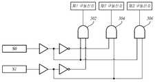
도 3은 본 발명의 실시 예에 따라 멀티플렉서 LED 구동IC내의 멀티플렉서 회로 구성 예를 도시한 그림이다.3 is a diagram illustrating an example of a multiplexer circuit configuration in a multiplexer LED driver IC according to an exemplary embodiment of the present invention.
도 4는 본 발명의 실시 예에 따라 선택신호에 따른 구동신호 출력 관계를 나타낸 테이블이다.4 is a table showing a driving signal output relationship according to a selection signal according to an embodiment of the present invention.
도 5는 본 발명의 실시 예에 따라 전원을 입력받아 구동신호를 출력하는 멀티플렉서 LED 구동IC의 개념도이다.5 is a conceptual diagram of a multiplexer LED driver IC receiving power and outputting a driving signal according to an exemplary embodiment of the present invention.
*도면의 주요 부분에 대한 부호의 설명** Description of the symbols for the main parts of the drawings *
202: 스위칭 선택단 204: 멀티플렉서 LED 구동IC202: switching select stage 204: multiplexer LED driver IC
206: 전원 210: LED 어레이206: power source 210: LED array
본 발명은 LED 백라이트에 관한 것이다.The present invention relates to an LED backlight.
LCD 모듈 등의 액정표시모듈은 자체 발광력이 없어 광원으로 백라이트유닛(BLU; backlight unit)을 사용하는데, 백라이트유닛의 광원으로는 램프가 이용되며, 다수의 이들 램프들이 백라이트 유닛의 프레임에 조립이 되어 도광판으로 광을 조사하게 된다. 상기 백라이트유닛은 램프(lamp)를 광원으로 이용하여 밝기가 균일한 면광원을 형성하는 구조로 되어 있다. 상기 램프는 소형이면서 고휘도 발광이 가능한 냉음극 형광램프(CCFL; Cold Cathode Fluorescent Lamp)가 사용될 수 있으며, 최근에는 상기 냉음극 형광램프(CCFL) 대신 발광다이오드(LED)를 적용하여 백라이트를 구현하고 있다. 이러한 LED 백라이트는 환경친화적이면서도 소비전력이 낮고, 명암비와 색 재현성 등이 뛰어나 새로운 광원으로 각광받고 있는 소재다.Liquid crystal display modules, such as LCD modules, do not have self-luminous power and use a backlight unit (BLU) as a light source. Lamps are used as a light source of the backlight unit, and many of these lamps are easily assembled to a frame of the backlight unit. The light is irradiated onto the light guide plate. The backlight unit has a structure of forming a surface light source with uniform brightness by using a lamp as a light source. The lamp may be a cold cathode fluorescent lamp (CCFL) capable of small size and high brightness, and recently, a backlight is implemented by applying a light emitting diode (LED) instead of the cold cathode fluorescent lamp (CCFL). . These LED backlights are environmentally friendly, low power consumption, excellent contrast ratio and color reproducibility, and are attracting attention as a new light source.
도 1은 상기 백라이트 유닛이 액정패널과 결합한 모습을 도시한 단면도이다.1 is a cross-sectional view illustrating a state in which the backlight unit is combined with a liquid crystal panel.
제1 투명유리기판(110;Thin Film Transistor Glass, 이하 'TFT Glass'라 함)의 윗면에는 복수의 서브픽셀들이 구비되고, 상기 서브픽셀에는 외부의 전기적인 신호에 의하여 각각의 서브픽셀을 구동하기 위한 박막 트랜지스터(140)가 구비되어 있으며, 상기 TFT Glass의 상부에 위치하는 제2 투명유리기판(120;Color Filter Glass, 이하 'C/F Glass'라 함)의 하부에는 상기 TFT Glass(110)상에 형성된 상기 서브픽셀과 대응되는 위치에 적색, 녹색, 청색 컬러필터(160, 162, 164)와 상기 TFT Glass(110)와 C/F Glass(120)의 사이에의 액정층(130), 상기 TFT Glass(110) 하부에서 백색광을 조사하는 백라이트 유닛(150)을 포함하며, 디스플레이 모드 및 스캔 모드가 선택적으로 구동되고, 상기 스캔 모드에서 상기 디스플레이 박막 트랜지스터(140)에 서로 다른 계조 전압을 인가하여 상기 백라이트 유닛(150)으로부터 조사되는 화이트(white) LED(152)로부터 백색광을 적색, 녹색, 청색의 단색광으로 분리한다.A plurality of subpixels are provided on an upper surface of the first transparent glass substrate 110 (hereinafter referred to as TFT glass), and the subpixels drive each subpixel by an external electrical signal. A
각각의 컬러필터는 적색, 녹색 또는 청색 영역의 광 중에서 어느 한 영역의 광만을 통과시키기 때문에 투과율이 30% 정도에 불과하다. 다른 광학 부품들의 광손실까지 고려하면, 백라이트 유닛에서 방출된 광의 10%만이 전달되며, 이러한 액정 디스플레이 장치의 광손실 중 컬러필터에 의한 광손실이 가장 큰 비중을 차지한다. 또한, 컬러필터의 성능에 따라 액정 디스플레이 장치의 색재현성이 현저하게 차이가 난다.Each color filter transmits only light in any one of the red, green, or blue regions, and thus transmittance is only about 30%. Considering the optical loss of other optical components, only 10% of the light emitted from the backlight unit is transmitted, and the optical loss of the liquid crystal display device is caused by the color filter. In addition, the color reproducibility of the liquid crystal display device is remarkably different depending on the performance of the color filter.
백라이트의 화이트 단일색을 광원으로 사용할 경우, 화이트 색상에서 색을 분리하여 RGB 색상을 만들어 냄으로 인하여 NTSC(National Television Systems Committee) 방식과 대비할 때 색 재현율이 떨어지는 문제가 있다.When a single white color of the backlight is used as a light source, color reproducibility is lowered when compared to the NTSC (National Television Systems Committee) method because the RGB color is generated by separating the color from the white color.
본 발명은 LED 구동IC를 통해 백라이트 LED를 순차 구동하는 방안을 제안한다.The present invention proposes a method of sequentially driving a backlight LED through the LED driving IC.
본 발명의 LED 백라이트는, R,G,B 색상을 달리하는 제1LED, 제2LED, 제3LED 의 구동을 결정하는 선택신호가 출력되는 스위칭 선택단과, 상기 선택신호가 멀티플렉싱(MUX)되어 상기 제1LED, 제2LED, 제3LED로 구동신호가 출력되는 멀티플렉서 LED구동 IC와, 상기 멀티플렉서 LED구동 IC의 구동신호 출력에 따라 각각의 LED가 순차적으로 구동되는 LED 어레이를 포함한다.The LED backlight of the present invention includes a switching selection stage for outputting a selection signal for determining driving of the first, second, and third LEDs having different R, G, and B colors, and the selection signal is multiplexed (MUX) to the first LED. A multiplexer LED driver IC outputs driving signals to the second and third LEDs, and an LED array in which each LED is sequentially driven according to the driving signal output of the multiplexer LED driver IC.
또한, 상기 멀티플렉서 LED구동 IC는, 두 개의 제1,제2선택신호 입력과 세 개의 구동신호 출력으로서 멀티플렉싱한다.The multiplexer LED driver IC multiplexes as two first and second select signal inputs and three drive signal outputs.
또한, 상기 멀티플렉서 LED구동 IC는, 상기 제1,제2선택신호가 '00' 일 때는 모든 LED를 오프시키며, 상기 제1,제2선택신호가 '10' 일 때는 상기 제1LED를 구동시키는 제1구동신호를 출력하며, 상기 제1,제2선택신호가 '01' 일 때는 제2LED를 구동시키는 제2구동신호를 출력하며, 상기 제1,제2선택신호가 '11' 일 때는 제3LED를 구동시키는 제3구동신호를 출력한다.The multiplexer LED driver IC is configured to turn off all LEDs when the first and second selection signals are '00', and to drive the first LEDs when the first and second selection signals are '10'. Outputs a first driving signal, and outputs a second driving signal for driving a second LED when the first and second selection signals are '01'; and a third LED when the first and second selection signals are '11'. And outputs a third driving signal for driving.
또한, 상기 멀티플렉서 LED구동 IC는, 상기 제1선택신호와 상기 제2선택신호의 반전값을 논리곱하여 제1구동신호로 출력하는 제1 AND 논리소자와, 상기 제1선택신호의 반전값과 상기 제2선택신호를 논리곱하여 제2구동신호로 출력하는 제2 AND 논리소자와, 상기 제1선택신호와 상기 제2선택신호를 논리곱하여 제3구동신호로 출력하는 제3 AND 논리소자를 포함한다.The multiplexer LED driver IC may include a first AND logic element for performing an AND operation on an inverted value of the first selection signal and the second selection signal to output a first driving signal, an inversion value of the first selection signal, and the And a second AND logic element for performing an AND operation on the second selection signal to output the second driving signal, and a third AND logic element for performing an AND operation on the first selection signal and the second selection signal to output the third driving signal. .
또한, 상기 멀티플렉서 LED구동 IC는, 외부로부터 전원을 입력받아 상기 선택신호에 따른 상기 구동신호를 생성함을 특징으로 한다.The multiplexer LED driver IC may receive power from an external source and generate the driving signal according to the selection signal.
이하, 본 발명의 바람직한 실시 예들의 상세한 설명이 첨부된 도면들을 참조 하여 설명될 것이다. 하기에서 각 도면의 구성요소들에 참조부호를 부가함에 있어 동일한 구성요소들에 대해서는 비록 다른 도면상에 표시되더라도 가능한 한 동일한 부호를 가지도록 하고 있음에 유의해야 한다.Hereinafter, the detailed description of the preferred embodiments of the present invention will be described with reference to the accompanying drawings. In the following description of the reference numerals to the components of the drawings it should be noted that the same reference numerals as possible even if displayed on different drawings.
도 2는 본 발명의 실시 예에 따른 LED백라이트의 구동 회로 블록도이다.2 is a block diagram of a driving circuit of the LED backlight according to an embodiment of the present invention.
먼저, 이하의 실시 예 설명에서는, 제1 LED로서 레드(R) LED, 제2 LED로서 그린(G) LED, 제3 LED로서 블루(B) LED를 예로 들어 설명할 것이나. 이는 하나의 실시 예에 불과할 뿐 각 LED의 색상은 이에 한정되지 않고 제1 LED가 그린(G) LED로 구현될 수 있음은 자명하다.First, in the following description of the embodiment, a red (R) LED as the first LED, a green (G) LED as the second LED, and a blue (B) LED as the third LED will be described as an example. This is only one embodiment, and the color of each LED is not limited thereto, and it is obvious that the first LED may be implemented as a green (G) LED.
선택신호 입력단(202)은 구동할 LED를 선택하는 선택신호를 멀티플렉서 LED 구동IC(204)로 제공하는 기능을 수행하는데, 본 발명에서는 제1선택신호(S0), 제2선택신호(S1)의 2비트로 구현한다. 상기 선택신호의 비트 수는 상기 2비트 이외에도 2비트 이상의 비트로 설정할 수 있다. 상기 제1선택신호와 제2선택신호의 값에 따라 멀티플렉서 LED 구동IC(204)는 동작시킬 LED(210)에 대해 구동신호를 출력한다.The selection
예를 들어, 모든 LED를 오프시키고자 할 때는 상기 제1,제2선택신호(S0,S1)를 '00'으로 하여 멀티플렉서 LED 구동IC(204)로 제공하며, 레드(R) LED를 구동시키고자 할 때는 상기 제1,제2선택신호를 '10'으로 하여 멀티플렉서 LED 구동IC(204)로 제공하며, 그린(G) LED를 구동시키고자 할 때는 상기 제1,제2선택신호를 '01'로 하여 멀티플렉서 LED 구동IC로 제공하며, 블루(B) LED를 구동시키고자 할 때는 상기 제1,제2선택신호를 '11'로 하여 멀티프렉서 LED 구동IC(204)로 제공한 다.For example, when the LEDs are to be turned off, the first and second selection signals S0 and S1 are set to '00' to be provided to the multiplexer
멀티플렉서 LED 구동IC(204)는 LED 어레이(210)를 구동시키는 인버터를 포함한 구동 드라이버로서, 본 발명은 이러한 구동 드라이버 기능에 멀티플렉서 기능을 추가한 특징을 가진다. 두 개의 제1,제2선택신호(S0,S1)를 입력으로 받아들여 어느 하나의 구동신호 출력으로서 멀티플렉싱한다. 즉, 멀티플렉서 LED 구동IC(204)는 선택신호(S0,S1)Z를 입력받아 이들의 선택신호 입력값에 따라 4가지의 구동신호를, 즉, 레드 LED 구동 온 또는 그린 LED 구동 온 또는 블루 LED 구동 온 또는 전체 모든 LED를 오프 시키는 구동신호를 출력한다. 따라서 상기 선택신호의 값에 따라 상기와 같은 4가지 형태의 구동신호가 출력될 수 있다. 따라서 LED 어레이(210)는 상기 멀티플렉서 LED구동 IC의 구동신호 출력에 따라 각각의 LED가 순차적으로 구동된다. 각 LED 어레이는 접지 그라운드와 각각 연결된다.The multiplexer LED driver IC 204 is a drive driver including an inverter for driving the
한편, 상기 멀티플렉서 LED 구동IC(204)는, 상기와 같은 멀티플렉싱을 수행하기 위하여 내부에 멀티플렉서를 구비하고 있는데, 이러한 멀티플렉서의 회로구성 예를 도 3에 도시하였다. 상기 멀티플렉서 LED 구동IC(204)는 도 3에 도시한 바와 같이, 상기 제1선택신호와 상기 제2선택신호의 반전값을 논리곱하여 제1구동신호로 출력하는 제1 AND 논리소자(302)와, 상기 제1선택신호의 반전값과 상기 제2선택신호를 논리곱하여 제2구동신호로 출력하는 제2 AND 논리소자(304)와, 상기 제1선택신호와 상기 제2선택신호를 논리곱하여 제3구동신호로 출력하는 제3 AND 논리소자(306)를 포함한다.Meanwhile, the multiplexer LED driver IC 204 includes a multiplexer therein to perform the multiplexing as described above. An example of the circuit configuration of the multiplexer is illustrated in FIG. 3. As shown in FIG. 3, the multiplexer LED driver IC 204 includes a first
상기 제1 AND 논리소자(302)에서 출력되는 제1구동신호는 레드 LED(제1 LED)에 공급되고, 상기 제2 AND 논리소자(304)에서 출력되는 제2구동신호는 그린 LED(제2 LED)에 공급되고, 상기 제3 AND 논리소자(306)에서 출력되는 제3구동신호는 블루 LED(제3 LED)에 공급된다.The first driving signal output from the first AND
따라서 상기 멀티플렉서 LED 구동IC(204)는 상기 도 3의 MUX 회로 구성을 포함함으로써, 도 4의 테이블과 같이 제1선택신호(S0), 제2선택신호(S1)가 '00' 일 때는 모든 LED를 오프시키며, 제1,제2선택신호가 '10' 일 때는 상기 제1LED를 구동시키는 제1구동신호를 출력하며, 제1,제2선택신호가 '01' 일 때는 제2LED를 구동시키는 제2구동신호를 출력하며, 제1,제2선택신호가 '11' 일 때는 제3LED를 구동시키는 제3구동신호를 출력한다. R/G/B LED를 시분할하여 구동하는 디스플레이의 경우 각각의 LED를 순차구동 순서에 따라 제어한다.Therefore, the multiplexer LED driving IC 204 includes the MUX circuit configuration of FIG. 3, so that all LEDs when the first selection signal S0 and the second selection signal S1 are '00' as shown in the table of FIG. 4. The first driving signal for driving the first LED when the first and second selection signals are '10', and the second driving driving second LED when the first and second selection signals are '01'. Outputs a second drive signal; and outputs a third drive signal for driving the third LED when the first and second selection signals are '11'. In the case of a display driven by time division of R / G / B LEDs, each LED is controlled according to the sequential driving sequence.
한편, 상기 멀티플렉서 LED 구동IC(204)는, 도 2와 같이 외부로부터 전원(206)을 입력받아 상기 선택신호에 따른 상기 구동신호를 생성한다. 즉, 외부의 전원(206)으로부터 전력을 인가받아 LED를 구동시킬 수 있는 안정적인 구동전력을 생성한 후, 스위칭 선택단(202)의 선택신호에 따라 제1구동신호, 제2구동신호, 제3구동신호 중 어느 하나에 구동전력을 싣거나 모든 구동신호에 구동전력을 싣지 않는다. 이러한 개념 예시를 도 5에 도시하였는데, 외부의 전원을 입력받은 멀티플렉서 LED 구동IC는 안정적인 LED 구동전력을 생성하여 이러한 구동전력을 내부에서 멀티플렉싱 스위칭하여 선택된 구동신호 출력단에 실어서 출력한다.Meanwhile, the multiplexer
상술한 본 발명의 설명에서는 구체적인 실시 예에 관해 설명하였으나, 여러 가지 변형이 본 발명의 범위에서 벗어나지 않고 실시될 수 있다. 따라서 본 발명의 특허 범위는 상기 설명된 실시 예에 의하여 정할 것이 아니고 특허청구범위뿐 아니라 균등 범위에도 미침은 자명할 것이다.In the above description of the present invention, specific embodiments have been described, but various modifications may be made without departing from the scope of the present invention. Therefore, the scope of the present invention is not to be determined by the embodiments described above, but will be apparent in the claims as well as equivalent scope.
본 발명은, 먹스(MUX) 기능이 내장된 LED 구동IC를 통해 LED 백라이트의 구동제어를 수행함으로써, R/G/B LED 제어 회로를 더욱 간단하게 꾸밀 수 있으며 전력과 공간적 효율을 높일 수 있는 효과가 있다.The present invention, by performing the drive control of the LED backlight through the LED drive IC with a built-in MUX function, it is possible to more easily decorate the R / G / B LED control circuit and to increase the power and spatial efficiency There is.
Claims (5)
Translated fromKoreanPriority Applications (3)
| Application Number | Priority Date | Filing Date | Title |
|---|---|---|---|
| KR1020070072704AKR20090009436A (en) | 2007-07-20 | 2007-07-20 | LED backlight |
| PCT/KR2008/004186WO2009014344A2 (en) | 2007-07-20 | 2008-07-17 | Backlight and liquid crystal display device |
| US12/669,718US20100188438A1 (en) | 2007-07-20 | 2008-07-17 | Backlight and Liquid Crystal Display Device |
Applications Claiming Priority (1)
| Application Number | Priority Date | Filing Date | Title |
|---|---|---|---|
| KR1020070072704AKR20090009436A (en) | 2007-07-20 | 2007-07-20 | LED backlight |
Publications (1)
| Publication Number | Publication Date |
|---|---|
| KR20090009436Atrue KR20090009436A (en) | 2009-01-23 |
Family
ID=40281962
Family Applications (1)
| Application Number | Title | Priority Date | Filing Date |
|---|---|---|---|
| KR1020070072704AWithdrawnKR20090009436A (en) | 2007-07-20 | 2007-07-20 | LED backlight |
Country Status (3)
| Country | Link |
|---|---|
| US (1) | US20100188438A1 (en) |
| KR (1) | KR20090009436A (en) |
| WO (1) | WO2009014344A2 (en) |
Cited By (1)
| Publication number | Priority date | Publication date | Assignee | Title |
|---|---|---|---|---|
| US10424240B2 (en) | 2016-11-09 | 2019-09-24 | Samsung Electronics Co., Ltd. | LED display module and display apparatus |
Families Citing this family (47)
| Publication number | Priority date | Publication date | Assignee | Title |
|---|---|---|---|---|
| US8651726B2 (en) | 2010-11-19 | 2014-02-18 | Reald Inc. | Efficient polarized directional backlight |
| WO2012068532A2 (en) | 2010-11-19 | 2012-05-24 | Reald Inc. | Directional flat illuminators |
| US9250448B2 (en) | 2010-11-19 | 2016-02-02 | Reald Inc. | Segmented directional backlight and related methods of backlight illumination |
| US20140041205A1 (en) | 2010-11-19 | 2014-02-13 | Reald Inc. | Method of manufacturing directional backlight apparatus and directional structured optical film |
| US9237337B2 (en) | 2011-08-24 | 2016-01-12 | Reald Inc. | Autostereoscopic display with a passive cycloidal diffractive waveplate |
| US9235057B2 (en) | 2012-05-18 | 2016-01-12 | Reald Inc. | Polarization recovery in a directional display device |
| EP2850473B1 (en) | 2012-05-18 | 2018-09-12 | RealD Spark, LLC | Directional display apparatus |
| KR102062019B1 (en) | 2012-05-18 | 2020-01-03 | 리얼디 스파크, 엘엘씨 | Directionally illuminated waveguide arrangement |
| US9678267B2 (en) | 2012-05-18 | 2017-06-13 | Reald Spark, Llc | Wide angle imaging directional backlights |
| EP2850488A4 (en) | 2012-05-18 | 2016-03-02 | Reald Inc | Directional backlight |
| US9350980B2 (en) | 2012-05-18 | 2016-05-24 | Reald Inc. | Crosstalk suppression in a directional backlight |
| US9188731B2 (en) | 2012-05-18 | 2015-11-17 | Reald Inc. | Directional backlight |
| KR102099590B1 (en) | 2012-05-18 | 2020-04-10 | 리얼디 스파크, 엘엘씨 | Controlling light sources of a directional backlight |
| WO2014018269A1 (en) | 2012-07-23 | 2014-01-30 | Reald Inc. | Observer tracking autostereoscopic display |
| US9420266B2 (en) | 2012-10-02 | 2016-08-16 | Reald Inc. | Stepped waveguide autostereoscopic display apparatus with a reflective directional element |
| WO2014100753A1 (en) | 2012-12-21 | 2014-06-26 | Reald Inc. | Superlens component for directional display |
| CN111487707A (en) | 2013-02-22 | 2020-08-04 | 瑞尔D斯帕克有限责任公司 | directional backlight |
| KR102254799B1 (en) | 2013-06-17 | 2021-05-24 | 리얼디 스파크, 엘엘씨 | Controlling light sources of a directional backlight |
| EP3058562A4 (en) | 2013-10-14 | 2017-07-26 | RealD Spark, LLC | Control of directional display |
| KR102366346B1 (en) | 2013-10-14 | 2022-02-23 | 리얼디 스파크, 엘엘씨 | Light input for directional backlight |
| CN106062466B (en) | 2013-11-15 | 2020-01-31 | 瑞尔D斯帕克有限责任公司 | Directional backlight with light emitting element package |
| EP3161550A4 (en) | 2014-06-26 | 2018-04-18 | RealD Spark, LLC | Directional privacy display |
| WO2016057690A1 (en) | 2014-10-08 | 2016-04-14 | Reald Inc. | Directional backlight |
| US10356383B2 (en) | 2014-12-24 | 2019-07-16 | Reald Spark, Llc | Adjustment of perceived roundness in stereoscopic image of a head |
| RU2596062C1 (en) | 2015-03-20 | 2016-08-27 | Автономная Некоммерческая Образовательная Организация Высшего Профессионального Образования "Сколковский Институт Науки И Технологий" | Method for correction of eye image using machine learning and method of machine learning |
| WO2016168345A1 (en) | 2015-04-13 | 2016-10-20 | Reald Inc. | Wide angle imaging directional backlights |
| CN107850804B (en) | 2015-05-27 | 2021-06-11 | 瑞尔D斯帕克有限责任公司 | Wide-angle imaging directional backlight |
| US10475418B2 (en) | 2015-10-26 | 2019-11-12 | Reald Spark, Llc | Intelligent privacy system, apparatus, and method thereof |
| WO2017083526A1 (en) | 2015-11-10 | 2017-05-18 | Reald Inc. | Distortion matching polarization conversion systems and methods thereof |
| EP3374692B1 (en) | 2015-11-13 | 2021-02-24 | RealD Spark, LLC | Wide angle imaging directional backlights |
| WO2017083583A1 (en) | 2015-11-13 | 2017-05-18 | Reald Spark, Llc | Surface features for imaging directional backlights |
| CN114143495B (en) | 2016-01-05 | 2025-07-15 | 瑞尔D斯帕克有限责任公司 | Gaze Correction for Multi-View Images |
| EP3458897B1 (en) | 2016-05-19 | 2025-04-02 | RealD Spark, LLC | Wide angle imaging directional backlights |
| US10425635B2 (en) | 2016-05-23 | 2019-09-24 | Reald Spark, Llc | Wide angle imaging directional backlights |
| WO2018129059A1 (en) | 2017-01-04 | 2018-07-12 | Reald Spark, Llc | Optical stack for imaging directional backlights |
| EP3607387A4 (en) | 2017-04-03 | 2020-11-25 | RealD Spark, LLC | Segmented imaging directional backlights |
| US10126575B1 (en) | 2017-05-08 | 2018-11-13 | Reald Spark, Llc | Optical stack for privacy display |
| CN116841075A (en) | 2017-05-08 | 2023-10-03 | 瑞尔D斯帕克有限责任公司 | Optical stack for directional display |
| US10303030B2 (en) | 2017-05-08 | 2019-05-28 | Reald Spark, Llc | Reflective optical stack for privacy display |
| CN111183405A (en) | 2017-08-08 | 2020-05-19 | 瑞尔D斯帕克有限责任公司 | Adjust the digital representation of the head area |
| TWI878209B (en) | 2017-09-15 | 2025-04-01 | 美商瑞爾D斯帕克有限責任公司 | Display device and a view angle control optical element for application to a display device |
| WO2019090246A1 (en) | 2017-11-06 | 2019-05-09 | Reald Spark, Llc | Privacy display apparatus |
| KR102759510B1 (en) | 2018-01-25 | 2025-02-04 | 리얼디 스파크, 엘엘씨 | Touchscreen for privacy display |
| US10976578B2 (en) | 2018-01-25 | 2021-04-13 | Reald Spark, Llc | Reflective optical stack for privacy display |
| CN116194812A (en) | 2020-09-16 | 2023-05-30 | 瑞尔D斯帕克有限责任公司 | Vehicle Exterior Lighting |
| US11966049B2 (en) | 2022-08-02 | 2024-04-23 | Reald Spark, Llc | Pupil tracking near-eye display |
| WO2024035796A1 (en) | 2022-08-11 | 2024-02-15 | Reald Spark, Llc | Anamorphic directional illumination device |
Family Cites Families (11)
| Publication number | Priority date | Publication date | Assignee | Title |
|---|---|---|---|---|
| EP0528797B1 (en)* | 1989-12-22 | 1996-02-07 | David Sarnoff Research Center, Inc. | Field-sequential display system utilizing a backlit lcd pixel array and method for forming an image |
| JPH07281647A (en)* | 1994-02-17 | 1995-10-27 | Aoki Kazuo | Color panel display device |
| JP3969862B2 (en)* | 1998-10-02 | 2007-09-05 | キヤノン株式会社 | Color liquid crystal display |
| KR100389026B1 (en)* | 2001-07-26 | 2003-06-25 | 엘지.필립스 엘시디 주식회사 | Apparatus and method for driving backlight of liquid crystal display device |
| US6975369B1 (en)* | 2002-12-12 | 2005-12-13 | Gelcore, Llc | Liquid crystal display with color backlighting employing light emitting diodes |
| KR100561053B1 (en)* | 2004-03-30 | 2006-03-21 | 아진테크주식회사 | Door hinge |
| US7714832B2 (en)* | 2004-06-02 | 2010-05-11 | Research In Motion Limited | Mixed monochrome and colour display driving technique |
| US7675249B2 (en)* | 2004-07-12 | 2010-03-09 | Sony Corporation | Apparatus and method for driving backlight unit |
| KR100755565B1 (en)* | 2005-10-14 | 2007-09-06 | 비오이 하이디스 테크놀로지 주식회사 | LCD Display |
| KR100755624B1 (en)* | 2006-02-09 | 2007-09-04 | 삼성전기주식회사 | LCD in field sequential color mode |
| US7750887B2 (en)* | 2006-12-21 | 2010-07-06 | Itt Manufacturing Enterprises, Inc. | Displays with large dynamic range |
- 2007
- 2007-07-20KRKR1020070072704Apatent/KR20090009436A/ennot_activeWithdrawn
- 2008
- 2008-07-17WOPCT/KR2008/004186patent/WO2009014344A2/enactiveApplication Filing
- 2008-07-17USUS12/669,718patent/US20100188438A1/ennot_activeAbandoned
Cited By (1)
| Publication number | Priority date | Publication date | Assignee | Title |
|---|---|---|---|---|
| US10424240B2 (en) | 2016-11-09 | 2019-09-24 | Samsung Electronics Co., Ltd. | LED display module and display apparatus |
Also Published As
| Publication number | Publication date |
|---|---|
| WO2009014344A3 (en) | 2009-03-19 |
| WO2009014344A2 (en) | 2009-01-29 |
| US20100188438A1 (en) | 2010-07-29 |
Similar Documents
| Publication | Publication Date | Title |
|---|---|---|
| KR20090009436A (en) | LED backlight | |
| JP4760920B2 (en) | Color display device | |
| KR101804466B1 (en) | Backlight having blue light emitting diodes and method of driving same | |
| RU2455706C2 (en) | Illumination device having array of controlled emitters | |
| TWI390495B (en) | Color sequential backlight liquid crystal displays and related methods | |
| US8482512B2 (en) | Liquid crystal backlight apparatus | |
| US20130278650A1 (en) | Color image display device and control method thereof | |
| JP2006019736A (en) | Backlight device for display device, light source for display device, light emitting diode for light source | |
| KR20070073765A (en) | Light source unit for backlight, backlight device for liquid crystal display and transmissive liquid crystal display device | |
| JP2009053687A (en) | Backlight unit and method of using the same | |
| TW201042626A (en) | Liquid crystal display and driving method of liquid crystal display | |
| JP2007280960A (en) | Backlight unit using light-emitting-diode | |
| KR20080035328A (en) | Back light assembly and display device having same | |
| US20090184660A1 (en) | Blacklight Unit and Display Device Including the Same | |
| US8791966B2 (en) | Display device and electric apparatus | |
| TW200820185A (en) | Color sequential liquid crystal display | |
| KR20160108783A (en) | Display apparatus and method of driving the same | |
| CN105009196B (en) | Display device and radiovisor | |
| TWI599824B (en) | Display device, display device driving method | |
| US20120001964A1 (en) | Liquid crystal display apparatus | |
| KR20080092599A (en) | Full Color LED Control Backlight Unit | |
| KR20070100040A (en) | Backlight unit for liquid crystal display using LED | |
| US8624827B2 (en) | Field sequential display device having longer black insertion period and a plurality of display areas | |
| JP2010266746A (en) | Liquid crystal display | |
| JP2006164631A (en) | Lighting system, plane display device, and lighting method |
Legal Events
| Date | Code | Title | Description |
|---|---|---|---|
| PA0109 | Patent application | Patent event code:PA01091R01D Comment text:Patent Application Patent event date:20070720 | |
| PG1501 | Laying open of application | ||
| PC1203 | Withdrawal of no request for examination | ||
| WITN | Application deemed withdrawn, e.g. because no request for examination was filed or no examination fee was paid |