KR20090008708A - Counterfeit Identification Using Contact Image Sensor - Google Patents
Counterfeit Identification Using Contact Image SensorDownload PDFInfo
- Publication number
- KR20090008708A KR20090008708AKR1020070071879AKR20070071879AKR20090008708AKR 20090008708 AKR20090008708 AKR 20090008708AKR 1020070071879 AKR1020070071879 AKR 1020070071879AKR 20070071879 AKR20070071879 AKR 20070071879AKR 20090008708 AKR20090008708 AKR 20090008708A
- Authority
- KR
- South Korea
- Prior art keywords
- light
- image sensor
- bill
- contact image
- light source
- Prior art date
- Legal status (The legal status is an assumption and is not a legal conclusion. Google has not performed a legal analysis and makes no representation as to the accuracy of the status listed.)
- Withdrawn
Links
- 238000000034methodMethods0.000claimsabstractdescription22
- 238000012545processingMethods0.000description10
- 238000004566IR spectroscopyMethods0.000description4
- 238000012546transferMethods0.000description3
- 238000010586diagramMethods0.000description2
- 230000001678irradiating effectEffects0.000description2
- 238000003780insertionMethods0.000description1
- 230000037431insertionEffects0.000description1
- 239000011159matrix materialSubstances0.000description1
- 238000012986modificationMethods0.000description1
- 230000004048modificationEffects0.000description1
- 238000005070samplingMethods0.000description1
- 230000000007visual effectEffects0.000description1
Images


Classifications
- G—PHYSICS
- G07—CHECKING-DEVICES
- G07D—HANDLING OF COINS OR VALUABLE PAPERS, e.g. TESTING, SORTING BY DENOMINATIONS, COUNTING, DISPENSING, CHANGING OR DEPOSITING
- G07D7/00—Testing specially adapted to determine the identity or genuineness of valuable papers or for segregating those which are unacceptable, e.g. banknotes that are alien to a currency
- G07D7/06—Testing specially adapted to determine the identity or genuineness of valuable papers or for segregating those which are unacceptable, e.g. banknotes that are alien to a currency using wave or particle radiation
- G07D7/12—Visible light, infrared or ultraviolet radiation
- G07D7/128—Viewing devices
- G—PHYSICS
- G07—CHECKING-DEVICES
- G07D—HANDLING OF COINS OR VALUABLE PAPERS, e.g. TESTING, SORTING BY DENOMINATIONS, COUNTING, DISPENSING, CHANGING OR DEPOSITING
- G07D2211/00—Paper-money handling devices
Landscapes
- Health & Medical Sciences (AREA)
- General Health & Medical Sciences (AREA)
- Toxicology (AREA)
- Physics & Mathematics (AREA)
- General Physics & Mathematics (AREA)
- Inspection Of Paper Currency And Valuable Securities (AREA)
Abstract
Translated fromKoreanDescription
Translated fromKorean본 발명은 컨택 이미지 센서를 이용한 위폐 식별방법에 관한 것으로서, 더욱 상세하게는 수광부의 센서를 지폐의 진위 식별을 위한 최소한의 데이터를 획득할 수 있는 동시에 지폐의 소정 위치에서 컬러패턴을 획득할 수 있도록 운영함으로써 지폐의 진위 식별에 대한 변별력과 판단결과의 신뢰성을 향상시킬 수 있는 컨택 이미지 센서를 이용한 위폐 식별방법에 관한 것이다.The present invention relates to a counterfeit identification method using a contact image sensor. More specifically, the sensor of the light receiving unit can acquire a minimum of data for authenticity identification of a bill and at the same time obtain a color pattern at a predetermined position of the bill. The present invention relates to a counterfeit identification method using a contact image sensor that can improve the discriminating power of authenticity of banknotes and the reliability of judgment results.
종래 금융자동화기기의 은행권인식장치는 지폐(은행권 및 유가증권)를 이송시키는 이송부가 구비되고, 이송부의 상,하에는 소정의 간격을 두고 쌍으로 이루어진 다수개의 적외선파장 광원 및 수광센서를 고정 설치하여 지폐가 이송될 때 지폐에 표시되어 있는 적외선 잉크패턴을 감지하여 지폐의 진위 및 권종을 판별할 수 있도록 구성된다.The banknote recognition device of the conventional automatic teller machine is provided with a transfer unit for transferring banknotes (banknotes and securities), and fixedly installed a plurality of infrared wavelength light source and a light receiving sensor formed in pairs at predetermined intervals above and below the transfer unit. When the banknotes are transferred, it is configured to detect the infrared ink pattern displayed on the banknotes to determine the authenticity and the paper type of the banknotes.
그러나, 이러한 방식의 은행권인식장치는 지폐가 통과할 때 적외선파장 광원 및 수광센서가 한 포인트의 적외선 잉크패턴만을 검출하기 때문에 지폐가 이송되면서 좌우로 이동이 생기면 수광센서에서 검출된 신호가 매번 다르게 추출되어 오인 식 또는 미인식되는 문제점이 있다.However, in this type of banknote recognition device, when the banknote passes, the infrared wavelength light source and the light receiving sensor detect only one point of the infrared ink pattern. There is a problem of being misrecognized or unrecognized.
한편, 종래의 또 다른 방식의 은행권인식장치로는 지폐에 표시된 적외선 잉크패턴을 검출하기 위해 동일한 파장의 적외선파장 광원을 구비한 컨택 이미지센서를 사용하는 방식이 있다. 이 컨택 이미지센서는 광원, 렌즈, 센서 부분이 일체화된 소형 화상입력장치로써, 접촉된 대상물의 영상을 얻기 위해 광원을 필요로 하는데, 현재 사용되고 있는 모든 컨택 이미지센서의 전체 광원은 단일 파장대 광원으로 제작 사용되고 있다. 그리고 이미지 센서의 종류는 사용 목적에 따라 가시광선 광원을 사용한 센서와 적외선광원을 사용한 센서 및 컬러광원을 사용한 센서로 구분된다.On the other hand, another conventional banknote recognition device is a method using a contact image sensor having an infrared wavelength light source of the same wavelength to detect the infrared ink pattern displayed on the bill. The contact image sensor is a compact image input device in which the light source, the lens, and the sensor part are integrated. A light source is required to obtain an image of the contacted object. All the light sources of all currently used contact image sensors are manufactured as a single wavelength light source. It is used. The image sensor is classified into a sensor using a visible light source, a sensor using an infrared light source, and a sensor using a color light source according to the purpose of use.
그러나, 은행권 및 유가증권에 적용된 위조방지요소인 적외선 잉크패턴은 통상적으로 글자나 부분적인 패턴에만 적용되고 나머지 영역은 가시광선 잉크패턴이 사용된다. 따라서 적외선파장 광원의 특성상 적외선 잉크패턴이 적용된 영역은 검정색 패턴으로 나타나고, 다른 영역 즉 가시광선 잉크패턴이 적용된 영역은 아무 영상이 나타나지 않게 된다. 그러므로 은행권의 테두리 경계선이 명확하지 않게 표시되어 구별이 어려운 문제가 있다. 즉, 패턴을 인식하고 판별하기 위해서는 패턴의 정확한 위치와 크기가 필수 요소인데, 희미하게 표시되어 정확한 구분이 어려운 경계선을 기준으로 패턴을 분석하게 되면 오차가 생겨 진위 식별 및 권종 구분에 한계가 생긴다.However, the infrared ink pattern, which is an anti-counterfeiting element applied to banknotes and securities, is typically applied only to letters or partial patterns, and the remaining area uses a visible light ink pattern. Therefore, due to the characteristics of the infrared wavelength light source, the region to which the infrared ink pattern is applied is shown as a black pattern, and the other region, that is, the region to which the visible light ink pattern is applied, does not appear any image. Therefore, there is a problem that is difficult to distinguish because the border of the banknote is not clearly displayed. In other words, the exact position and size of the pattern is essential for recognizing and discriminating the pattern. However, if the pattern is analyzed based on a borderline that is blurred and cannot be accurately distinguished, an error occurs and thus there is a limit in authenticity identification and classification of the class.
한편, 컨택 이미지센서를 이용하여 지폐로부터 컬러패턴을 식별하는 방법은, RGB 삼색광원과 적외선광원을 순차적으로 점등시켜 지폐에 반사되거나 투과한 빛을 수광부의 센서를 통해 감지하고, 이를 샘플링하여 컬러패턴과 이미지를 획득하고 있다. 예를 들어 지폐가 400ms의 속도로 이동할 때 R광원, G광원, B광원 및 IR광원을 순차적으로 점등시켜, 도 1에 도시된 바와 같이 지폐의 선구간 데이터, 다시 말해서 한 라인에 R, G, B, IR에 대한 파장을 획득하였다. 각 선구간별로 획득된 R, G, B 세 개의 데이터를 조합하여 컬러패턴을 검출하고, IR데이터로부터 이미지패턴을 검출하였다.On the other hand, the method for identifying the color pattern from the bill using the contact image sensor, by sequentially lighting the RGB tricolor light source and infrared light source to detect the light reflected or transmitted through the bill through the sensor of the light receiving unit, and sampling the color pattern And images are acquired. For example, when the bill moves at a speed of 400 ms, the R light source, the G light source, the B light source, and the IR light source are sequentially turned on, and as shown in FIG. 1, the data of the line segment of the bill, that is, R, G, The wavelength for B, IR was obtained. A color pattern was detected by combining three pieces of R, G, and B data acquired for each line section, and an image pattern was detected from the IR data.
그러나 실제 ATM 운영필드에서 운영되는 금융자동화기기에서는 지폐가 1600ms로 지폐가 빠르게 통과하기 때문에 현재의 컨택 이미지센서로 상술한 바와 같이 선구간별로 데이터를 획득하기 어렵고, 이렇게 획득된 데이터는 4개의 라인당 1개의 데이터를 나타내기 때문에 지폐의 진위를 식별하기에는 너무 부족하였다.However, in the automated teller machine operating in the actual ATM operation field, since the bill passes quickly with 1600 ms, it is difficult to acquire data for each section as described above with the current contact image sensor. Since one piece of data is presented, it is too short to identify the authenticity of the bill.
이러한 문제점을 해결하기 위하여 현재의 컨택 이미지센서는 G와 IR 데이터를 획득하여 지폐의 진위를 식별하였으나 이러한 방법으로는 지폐로부터 컬러패턴을 획득할 수 없으므로 지폐의 진위를 정확하게 식별하기 어렵다는 문제점이 있다.In order to solve this problem, the current contact image sensor identifies the authenticity of banknotes by acquiring G and IR data, but it is difficult to accurately identify the authenticity of banknotes because it is impossible to obtain a color pattern from the banknotes in this way.
따라서, 본 발명은 상기한 문제점을 해결하기 위한 것으로, 수광부의 센서를 G와 IR 데이터를 교대로 획득하고 소정의 위치에서 R, G, B 데이터를 획득할 수 있도록 운영함으로써 지폐의 진위를 식별할 수 있는 데이터의 양을 증가시켜 지폐의 진위를 식별하는데 있어서 변별력과 정확한 식별 결과를 얻을 수 있도록 하는 컨택 이미지센서를 이용한 위폐 식별방법을 제공하는데 그 목적이 있다.Accordingly, the present invention is to solve the above problems, by operating the sensor of the light receiving unit to obtain the G and IR data alternately and to obtain the R, G, B data at a predetermined position to identify the authenticity of the bills. It is an object of the present invention to provide a counterfeit identification method using a contact image sensor that can increase the amount of data that can be used to obtain authenticity and accurate identification results.
상기한 목적을 달성하기 위하여 본 발명에 따른 컨택 이미지 센서를 이용한 위폐 식별방법은, 광원부와, 상기 광원부로부터 방출되는 광이 지폐를 투과 또는 반사된 광을 수광하는 수광부를 포함하여 구성되는 컨택 이미지 센서를 이용한 위폐 식별방법에 있어서, 상기 수광부는 지폐로부터 투과 또는 반사된 단색 가시광선과 적외선에 대한 선구간 데이터를 교대로 반복적으로 획득하여 지폐의 이미지를 식별하되, 상기 지폐의 소정 위치에 대응해서 RGB 광선에 대한 선구간 데이터를 획득하여 컬러패턴을 식별할 수 있도록 운영되는 것을 특징으로 한다.In order to achieve the above object, the forgery identification method using the contact image sensor according to the present invention comprises a light source unit and a light receiving unit for receiving light transmitted or reflected through the banknote light emitted from the light source unit In the counterfeit identification method using the above, the light-receiving unit alternately repeatedly acquires the line segment data for the monochromatic visible light and infrared rays transmitted or reflected from the banknote to identify the image of the banknote, RGB rays corresponding to the predetermined position of the banknote It is characterized in that it is operated to identify the color pattern by acquiring the line segment data for.
본 발명에 따른 컨택 이미지 센서를 이용한 위폐 식별방법은, 수광부의 센서를 IR 데이터와 G 데이터 및 RGB 컬러 데이터를 획득할 수 있도록 운용하여 지폐로부터 지폐의 진위를 식별할 수 있는 최소한의 데이터를 획득하여 이미지의 해상도를 향상시키는 동시에 컬러패턴을 식별할 수 있도록 운영함으로써 보다 정확하게 위폐를 식별할 수 있다는 효과가 있다.In the counterfeit identification method using the contact image sensor according to the present invention, by operating the sensor of the light-receiving unit to obtain the IR data, G data and RGB color data to obtain the minimum data that can identify the authenticity of the bill from the bill By improving the resolution of the image and operating to identify the color pattern, it is effective to identify the counterfeit more accurately.
이하, 본 발명의 실시예에 대하여 상세히 설명하지만, 본 발명은 그 요지를 이탈하지 않는 한 이하의 실시예에 한정되지 않는다.EMBODIMENT OF THE INVENTION Hereinafter, although the Example of this invention is described in detail, this invention is not limited to a following example, unless the summary is exceeded.
도 2는 본 발명에 따른 컨택 이미지 센서를 이용한 위폐 식별장치의 구성을 보여주는 블록도이다.2 is a block diagram showing the configuration of the forgery identification apparatus using a contact image sensor according to the present invention.
도 2를 참조하면, 컨택 이미지 센서를 이용한 위폐 식별장치는, 내부에 RGB 광원과 적외선(IR)광원을 구비하는 광원부(10)와, 광선을 지폐에 조사하여 해당 광선에 대한 지폐 상의 특수잉크의 반응을 인식하는 수광부(19)와, 조사되는 해당 광선에 대한 진본지폐의 기준 패턴 값이 저장되어 있는 데이터베이스(30)와, 수광부(19)에서 인식한 데이터를 조합하여 산출한 패턴 값과 데이터베이스(30)에서 독출한 진본지폐의 기준 패턴 값을 비교하여 진위를 판단하는 중앙처리부(20)와, 중앙처리부(20)의 산출 패턴 값을 임시로 저장하는 임시저장부(22)와, 중앙처리부(20)의 지폐에 대한 진위 판단 결과를 외부로 출력해주는 표시부(40)를 포함하여 구성된다.Referring to FIG. 2, the counterfeit identification device using the contact image sensor includes a
광원부(10)에는 RGB 광원과 IR 광원이 지폐에 투과 또는 반사되어 수광부(19)에서 검출될 수 있도록 서로 인접하여 반복적으로 배열되어 있다. RGB 광원과 IR 광원으로부터 방출되는 광은 방사되기 때문에 조밀하게 배열되지 않아도 무방하다.The
수광부(19)에는 광을 검출하는 다수 개의 센서가 매트릭스형태로 배열되어 있다. 센서는 단색 광선과 적외선 또는 컬러광선과 적외선이 조사되는 지폐의 일측 면을 소정의 동일 면적을 갖는 이미지 영역으로 분할하고, 각각의 영역에서 지폐에 사용된 특수잉크와 반응하여 나타나는 명암 수치인 휘도 값과, 색상 수치인 색도 값을 인식한다.In the
이미지 영역은 지폐의 일측 모서리를 기준점으로 설정하고, 지폐의 길이방향과 폭 방향이 등간격으로 나누어져 각각의 이미지 영역은 기준점에 대해서 각각 특정한 위치 값을 가진다. 따라서, 지폐의 특정 영역에서 나타나는 특수잉크의 반응을 각 이미지 영역별로 명암 수치인 휘도 값과 색상 수치로 정확하게 인식할 수 있는데, 이미지 영역은 선구간으로 나누어져 점등되는 광원의 종류별로 광에 대한 데이터를 검출한다.The image area is set at one corner of the banknote as a reference point, and the length direction and the width direction of the banknote are divided at equal intervals so that each image area has a specific position value with respect to the reference point, respectively. Therefore, the reaction of the special ink appearing in the specific area of the banknote can be accurately recognized by the brightness value and the color value, which are the contrast values, for each image area. Detect.
데이터베이스(30)는 광원부(10)에서 진본지폐에 RGB 광선 및 적외선을 조사하고 인식하여 얻어진 기준 패턴 값을 저장하여 보관하는 역할을 한다. 또한, 데이터베이스(30)에는 동일한 하나의 지폐의 권종에 대한 기준 패턴 값도 일정한 범위내에서 지폐의 사용 정도 및 훼손 정도에 따라 각기 다른 패턴 값을 저장함으로써, 진위 판단 대상의 지폐가 새 지폐가 아닌 헌 지폐의 경우에도 본 발명에 따른 방법을 사용하여 지폐의 진위 여부를 판단할 수 있다.The
중앙처리부(20)는 각각의 장치들을 제어하고, 수광부(19)를 통해 이미지 영역에서 인식된 복수 개의 데이터를 연속된 데이터로 조합하고, 조합된 데이터에서 특정한 패턴 값을 산출하는 역할을 수행한다. 본 발명에서는 중앙처리부(20)가 수광부(19)의 센서에서 G광원과 IR광원으로부터 방출되는 광을 교대로 반복해서 검출 하고, 소정 위치에서는 RGB광원으로부터 방출되는 광을 연속적으로 검출할 수 있도록 운영한다.The
또한, 중앙처리부(20)는 산출된 패턴 값과 데이터베이스(30)에 저장된 진본지폐에 대한 기준 패턴 값과의 비교를 통해 지폐의 진위 판단을 수행한다.In addition, the
임시저장부(22)는 중앙처리부(20)의 패턴 값을 임시 저장하는 부분이며, 표시부(40)는 지폐에 대한 진위 여부 판단 결과를 외부로 표시해주는 부분으로, 외부에서 시각적으로 인식하는 디스플레이 또는 청각적으로 경고음을 발생하는 부저 장치 등으로 구성되며, 중앙처리부(20)의 제어에 의해 동작한다.The
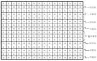
도 3은 본 발명에 따른 컨택 이미지 센서를 이용한 위폐 식별장치에 있어서, 수광부의 센서에서 데이터가 획득되는 일 예를 보여주는 도면으로서, 도 2와 연관하여 설명한다.3 is a view illustrating an example in which data is acquired from a sensor of a light receiving unit in the forgery identification apparatus using a contact image sensor according to the present invention, and will be described with reference to FIG. 2.
본 발명에 따른 컨택 이미지 센서를 이용한 위폐 식별방법은, 지폐를 컨택 이미지센서를 이용한 식별장치의 지폐 투입구에 투입하면, 지폐가 지폐 이송로를 따라 이동하고, 광원부(10)에서는 광원을 종류별로 순차적으로 점등하고, 수광부(19)에서는 점등되는 광원의 종류별로 지폐를 투과 또는 반사된 광을 수광부의 센서를 통해 수광한다. 이때, 광원부(10)에서는 G광원과 IR광원을 교대로 점등시키며, 지폐의 소정 위치, 다시 말해서 컬러패턴을 검출해야하는 영역에서는 RGB 광원을 순서에 관계없이 연속해서 점등한다.In the counterfeit identification method using the contact image sensor according to the present invention, when a bill is inserted into a bill insertion slot of an identification device using a contact image sensor, the bill is moved along a bill transfer path, and the
이렇게 해서 지폐를 투과 또는 지폐에 반사된 광은 수광부(19)의 센서에서 도 3에 도시된 바와 같이 나타나는데, G광원과 IR광원을 통한 데이터가 교대로 획득되고, 소정 위치, 지폐로부터 컬러패턴을 검출해야하는 영역에서는 RGB광원을 통한 데이터가 연속적으로 획득되어, 지폐로부터 이미지와 컬러패턴을 동시에 획득할 수 있다. 여기에서 IR광원을 통해서는 이미지를 얻고 RGB광원을 통해서는 컬러패턴을 획득한다고 했지만, 모든 데이터를 조합하면 결과적으로는 지폐의 이미지가 획득되게 된다.In this way, the light transmitted through the banknote or reflected on the banknote appears as shown in FIG. 3 in the sensor of the
수광부(19)에서 획득된 데이터는 중앙처리부(20)에서 연속된 데이터로 조합되고, 조합된 데이터에서 특정한 패턴 값을 산출되면, 데이터베이스(30)에 저장된 기준 패턴 값과 비교를 통해 지폐의 진위를 식별한다.The data obtained by the
이러한 방법으로 데이터를 획득하면 지폐의 진위를 식별할 수 있는 데이터의 양이 도 1에 도시된 방법에 비하여 증가하기 때문에 지폐의 진위를 정확하게 식별할 수 있고, 이미지 이외에도 컬러패턴까지 검출할 수 있으므로 지폐의 진위를 더욱 신속하고 정확하게 식별할 수 있다.Acquiring the data in this way increases the amount of data that can identify the authenticity of the banknote compared to the method shown in FIG. 1, so that the authenticity of the banknote can be accurately identified and color patterns can be detected in addition to the image. The authenticity of can be identified more quickly and accurately.
이와 같이, 본 발명의 상세한 설명에서는 구체적인 실시예에 관해 설명하였으나, 본 발명의 범주에서 벗어나지 않는 한도 내에서 여러 가지 변형이 가능함은 물론이다. 그러므로, 본 발명의 범위는 설명된 실시예에 국한되어 정해져서는 안되며, 후술하는 특허청구범위뿐만 아니라 이 청구범위와 균등한 것들에 의해 정해져야 한다.As described above, in the detailed description of the present invention, specific embodiments have been described, but various modifications are possible without departing from the scope of the present invention. Therefore, the scope of the present invention should not be limited to the described embodiments, but should be defined by the claims below and equivalents thereof.
도 1은 종래기술에 따른 컨택 이미지 센서를 이용한 위폐 식별장치에 있어서, 수광부의 센서에서 데이터가 획득되는 일 예를 보여주는 도면.1 is a view illustrating an example in which data is acquired from a sensor of a light receiving unit in a forgery discrimination apparatus using a contact image sensor according to the related art.
도 2는 본 발명에 따른 컨택 이미지 센서를 이용한 위폐 식별장치의 구성을 보여주는 블록도.Figure 2 is a block diagram showing the configuration of the forgery identification device using a contact image sensor according to the present invention.
도 3은 본 발명에 따른 컨택 이미지 센서를 이용한 위폐 식별장치에 있어서, 수광부의 센서에서 데이터가 획득되는 일 예를 보여주는 도면.3 is a view illustrating an example in which data is acquired from a sensor of a light receiver in the forgery identification apparatus using a contact image sensor according to the present invention;
<도면의 주요부분에 대한 부호의 설명><Description of the symbols for the main parts of the drawings>
10 : 광원부 19 : 수광부10
20 : 중앙처리부 22 : 임시저장부20: central processing unit 22: temporary storage unit
30 : 데이터베이스 40 : 표시부30: database 40: display unit
Claims (3)
Translated fromKoreanPriority Applications (1)
| Application Number | Priority Date | Filing Date | Title |
|---|---|---|---|
| KR1020070071879AKR20090008708A (en) | 2007-07-18 | 2007-07-18 | Counterfeit Identification Using Contact Image Sensor |
Applications Claiming Priority (1)
| Application Number | Priority Date | Filing Date | Title |
|---|---|---|---|
| KR1020070071879AKR20090008708A (en) | 2007-07-18 | 2007-07-18 | Counterfeit Identification Using Contact Image Sensor |
Publications (1)
| Publication Number | Publication Date |
|---|---|
| KR20090008708Atrue KR20090008708A (en) | 2009-01-22 |
Family
ID=40488740
Family Applications (1)
| Application Number | Title | Priority Date | Filing Date |
|---|---|---|---|
| KR1020070071879AWithdrawnKR20090008708A (en) | 2007-07-18 | 2007-07-18 | Counterfeit Identification Using Contact Image Sensor |
Country Status (1)
| Country | Link |
|---|---|
| KR (1) | KR20090008708A (en) |
Cited By (1)
| Publication number | Priority date | Publication date | Assignee | Title |
|---|---|---|---|---|
| KR101307424B1 (en)* | 2011-10-13 | 2013-09-11 | 한국조폐공사 | security module reading apparatus having a plural of light emitting display and method for reading security module |
- 2007
- 2007-07-18KRKR1020070071879Apatent/KR20090008708A/ennot_activeWithdrawn
Cited By (1)
| Publication number | Priority date | Publication date | Assignee | Title |
|---|---|---|---|---|
| KR101307424B1 (en)* | 2011-10-13 | 2013-09-11 | 한국조폐공사 | security module reading apparatus having a plural of light emitting display and method for reading security module |
Similar Documents
| Publication | Publication Date | Title |
|---|---|---|
| EP1490828B1 (en) | Currency verification | |
| EP3188138B1 (en) | Devices, systems, and methods for optical validation | |
| JP5691061B2 (en) | Banknote verification device | |
| US8265346B2 (en) | Determining document fitness using sequenced illumination | |
| US8483472B2 (en) | Paper sheet identifying device and paper sheet identifying method | |
| US8509515B2 (en) | Paper sheet identifying device and paper sheet identifying method | |
| GB2355522A (en) | Improvements in verifying printed security substrates | |
| KR101792690B1 (en) | Banknote processing device | |
| JP2001126107A (en) | Method and device for identifying paper sheets | |
| WO2011036748A1 (en) | Paper sheet identification device and paper sheet identification method | |
| JP7227818B2 (en) | Banknote identification device, banknote handling device, and banknote identification method | |
| US8265336B2 (en) | Paper identifying apparatus and paper identifying method | |
| JP5502111B2 (en) | Paper sheet identification device and paper sheet identification method | |
| JP4703403B2 (en) | Inspection device | |
| WO2012094896A1 (en) | Method and device for identifying banknotes or other financial notes | |
| KR101076322B1 (en) | Method for discriminating the authenticity of paper money by using a contact image sensor | |
| KR101992387B1 (en) | Integrated sensor module fo Bill counter | |
| KR101117359B1 (en) | Apparatus and method for medium recognition | |
| KR20120069841A (en) | A banknote discrimination apparatus using contact image sensor module | |
| KR20090008708A (en) | Counterfeit Identification Using Contact Image Sensor | |
| JP6751569B2 (en) | Method for detecting the document identification device, the document processor, the image sensor unit, and the optical variable element region | |
| KR20160113878A (en) | Recognition apparatus for face value of bill and detection apparatus for counterfiet bill | |
| KR100923082B1 (en) | Apparatus and method for discriminating paper currency of bills | |
| JP7337572B2 (en) | Serial number reading device, paper sheet processing device, and serial number reading method | |
| JP2009020707A (en) | Paper sheet identification device |
Legal Events
| Date | Code | Title | Description |
|---|---|---|---|
| PA0109 | Patent application | Patent event code:PA01091R01D Comment text:Patent Application Patent event date:20070718 | |
| PG1501 | Laying open of application | ||
| PC1203 | Withdrawal of no request for examination | ||
| WITN | Application deemed withdrawn, e.g. because no request for examination was filed or no examination fee was paid |