KR20090002411A - Lid lock of pressure cooker with steam discharge function - Google Patents
Lid lock of pressure cooker with steam discharge functionDownload PDFInfo
- Publication number
- KR20090002411A KR20090002411AKR1020070064190AKR20070064190AKR20090002411AKR 20090002411 AKR20090002411 AKR 20090002411AKR 1020070064190 AKR1020070064190 AKR 1020070064190AKR 20070064190 AKR20070064190 AKR 20070064190AKR 20090002411 AKR20090002411 AKR 20090002411A
- Authority
- KR
- South Korea
- Prior art keywords
- lid
- lever
- steam discharge
- opening
- steam
- Prior art date
- Legal status (The legal status is an assumption and is not a legal conclusion. Google has not performed a legal analysis and makes no representation as to the accuracy of the status listed.)
- Ceased
Links
- 235000013305foodNutrition0.000claimsabstractdescription5
- 238000003780insertionMethods0.000claimsdescription15
- 230000037431insertionEffects0.000claimsdescription15
- 238000000034methodMethods0.000claimsdescription6
- 238000009434installationMethods0.000abstractdescription7
- 238000007599dischargingMethods0.000description12
- 238000010411cookingMethods0.000description7
- 241000209094OryzaSpecies0.000description6
- 235000007164Oryza sativaNutrition0.000description6
- 235000009566riceNutrition0.000description6
- 230000008878couplingEffects0.000description4
- 238000010168coupling processMethods0.000description4
- 238000005859coupling reactionMethods0.000description4
- 230000000694effectsEffects0.000description2
- 238000001514detection methodMethods0.000description1
Images


Classifications
- A—HUMAN NECESSITIES
- A47—FURNITURE; DOMESTIC ARTICLES OR APPLIANCES; COFFEE MILLS; SPICE MILLS; SUCTION CLEANERS IN GENERAL
- A47J—KITCHEN EQUIPMENT; COFFEE MILLS; SPICE MILLS; APPARATUS FOR MAKING BEVERAGES
- A47J27/00—Cooking-vessels
- A47J27/08—Pressure-cookers; Lids or locking devices specially adapted therefor
- A47J27/09—Safety devices
- A47J27/092—Devices for automatically releasing pressure before opening
- A—HUMAN NECESSITIES
- A47—FURNITURE; DOMESTIC ARTICLES OR APPLIANCES; COFFEE MILLS; SPICE MILLS; SUCTION CLEANERS IN GENERAL
- A47J—KITCHEN EQUIPMENT; COFFEE MILLS; SPICE MILLS; APPARATUS FOR MAKING BEVERAGES
- A47J36/00—Parts, details or accessories of cooking-vessels
- A47J36/06—Lids or covers for cooking-vessels
- A47J36/10—Lid-locking devices
- Y—GENERAL TAGGING OF NEW TECHNOLOGICAL DEVELOPMENTS; GENERAL TAGGING OF CROSS-SECTIONAL TECHNOLOGIES SPANNING OVER SEVERAL SECTIONS OF THE IPC; TECHNICAL SUBJECTS COVERED BY FORMER USPC CROSS-REFERENCE ART COLLECTIONS [XRACs] AND DIGESTS
- Y10—TECHNICAL SUBJECTS COVERED BY FORMER USPC
- Y10S—TECHNICAL SUBJECTS COVERED BY FORMER USPC CROSS-REFERENCE ART COLLECTIONS [XRACs] AND DIGESTS
- Y10S220/00—Receptacles
- Y10S220/912—Cookware, i.e. pots and pans
Landscapes
- Engineering & Computer Science (AREA)
- Food Science & Technology (AREA)
- Cookers (AREA)
Abstract
Translated fromKoreanDescription
Translated fromKorean도 1은 종래기술에 따른 전기압력밥솥을 도시한 종단 측면도,Figure 1 is a longitudinal side view showing an electric pressure cooker according to the prior art,
도 2는 도 1의 전기압력밥솥의 뚜껑 잠금상태에서 증기배출수단의 작동상태를 나타내는 부분 종단 측면도,Figure 2 is a partial longitudinal side view showing the operating state of the steam discharge means in the lid lock state of the electric pressure cooker of Figure 1,
도 3은 도 1의 전기압력밥솥의 뚜껑 해제상태에서 증기배출수단의 작동상태를 나타내는 부분 종단 측면도,Figure 3 is a partial longitudinal side view showing the operating state of the steam discharge means in the lid release state of the electric pressure cooker of Figure 1,
도 4는 본 발명에 따른 증기배출 기능을 구비한 전기압력밥솥의 뚜껑 잠금장치를 도시한 분해 사시도,Figure 4 is an exploded perspective view showing a lid lock of the electric pressure cooker having a steam discharge function according to the present invention,
도 5는 본 발명의 제 1 실시예에 따른 작동 레버를 확대 도시한 사시도,5 is an enlarged perspective view of an operating lever according to a first exemplary embodiment of the present invention;
도 6은 본 발명의 제 2 실시예에 따른 작동 레버를 확대 도시한 사시도6 is an enlarged perspective view of an operating lever according to a second exemplary embodiment of the present invention;
도 7은 뚜껑 잠금시의 작동상태를 측면에서 도시한 도면,7 is a view showing the operation state at the time of locking the lid,
도 8은 뚜껑 잠금 해제시의 작동상태를 측면에서 도시한 도면.8 is a side view showing an operating state when the lid is unlocked.
- 도면의 주요부분에 대한 부호의 설명 --Explanation of symbols for the main parts of the drawings-
100: 뚜껑110: 증기배출수단100: lid 110: steam discharge means
111: 증기배출관112: 압력추111: steam discharge pipe 112: pressure weight
120: 핸들 부재121: 핸들120: handle member 121: handle
122: 핸들 샤프트123: 핸들 가이드122: handle shaft 123: handle guide
130: 개폐링131: 결합공130: opening and closing ring 131: coupling hole
132: 회동 레버140: 캠 부재132: rotation lever 140: cam member
141: 경사면150: 레버 부재141: inclined surface 150: lever member
151: 연동 레버152, 152': 작동 레버151: interlocking lever 152, 152 ': operating lever
153, 153': 몸체154, 154': 가압부153, 153 ':
155: 체결부재156, 156': 코일 스프링155: fastening
본 발명은 압력밥솥의 뚜껑 잠금장치에 관한 것으로서, 더욱 상세하게는 압력밥솥의 잠금 및 잠금 해제 작동과 연동되어 증기가 배출되도록 하는 작동 레버가 설치 공간의 제약을 받지 않도록 하여 제품의 설계 자유도를 향상시킬 수 있는 증기배출 기능을 구비한 압력밥솥의 뚜껑 잠금장치에 관한 것이다.The present invention relates to a lid locking device of the pressure cooker, and more particularly, in order to improve the design freedom of the product by operating the lever to interlock with the locking and unlocking operation of the pressure cooker so as not to be restricted by the installation space It relates to a lid lock of the pressure cooker having a steam discharge function that can be made.
일반적으로 전기압력밥솥은 압력에 의하여 취사를 수행하기 때문에 뚜껑이 완전히 닫혔는지의 여부를 감지하여 취사 시작 여부를 판단하도록 함과 동시에 취사 과정에서 밥솥 내부의 온도와 압력이 고온, 고압으로 되기 때문에 취사 완료 후 뚜껑이 완전히 개방되기 전에 내부의 고온, 고압의 증기와 공기를 외부로 배출하는 증기배출수단이 구비된다.In general, the electric pressure cooker is cooked by pressure, so it detects whether the lid is completely closed to judge whether cooking is started, and cooks because the temperature and pressure inside the cooker become high temperature and high pressure during cooking. After completion, the steam discharge means for discharging the high temperature and high pressure steam and air to the outside before the lid is fully opened is provided.
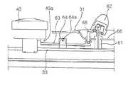
도 1은 종래기술에 따른 전기압력밥솥을 도시한 종단 측면도이고, 도 2는 도 1의 전기압력밥솥의 뚜껑 잠금상태에서 증기배출수단의 작동상태를 나타내는 부분 종단 측면도이며, 도 3은 도 1의 전기압력밥솥의 뚜껑 해제상태에서 증기배출수단의 작동상태를 나타내는 부분 종단 측면도이다.Figure 1 is a longitudinal side view showing an electric pressure cooker according to the prior art, Figure 2 is a partial longitudinal side view showing the operating state of the steam discharge means in the lid lock state of the electric pressure cooker of Figure 1, Figure 3 is Partial longitudinal side view showing the operating state of the steam discharge means in the lid release state of the electric pressure cooker.
도시된 바와 같이, 종래 전기압력밥솥의 뚜껑 잠금장치는 밥솥 본체(10)와, 밥솥 본체(10)의 내부에 삽입되는 내솥(20)과, 밥솥 본체(10)에 힌지로 개폐가능하게 결합되어 밥솥 본체(10)와 내솥(20)의 상부에 씌워지는 뚜껑(30)으로 구성된다.As shown, the lid locking device of the conventional electric pressure cooker is coupled to the
밥솥 본체(10)는 내솥(20)이 삽입되는 공간 외에도 각종 부품 즉, 히터, 제어회로부 등이 설치되는 공간부를 갖는다.In addition to the space in which the inner pot 20 is inserted, the cooker
내솥(20)은 상부가 개방되어 쌀 등의 조리물을 수용하며, 상단 가장자리에는 걸림돌기(21)가 외측으로 절곡 돌출되어 있다.The inner pot 20 is open at the top to accommodate foods such as rice, and the
뚜껑(30)은 외관을 이루는 뚜껑 본체(31)와, 이 뚜껑 본체(31)에 결합되는 뚜껑 프레임(33)과, 이 뚜껑 프레임(33)에 결합되어 내솥(20)을 개폐하는 내솥 뚜껑(34)으로 구성되며, 내솥 뚜껑(34)을 내솥(20)에 대하여 닫힌 상태로 잠그는 내솥 뚜껑 잠금수단과, 내솥 뚜껑 잠금수단에 의한 뚜껑 잠금 여부를 감지하는 내솥 뚜껑 잠김여부 감지수단 및, 내솥(20) 내부의 고온, 고압의 증기를 배출시키기 위한 증기배출수단이 구비된다.The
한편, 증기배출수단은 뚜껑 본체(31)의 일측에서 상단이 뚜껑 본체(31)의 상면에 이르며, 하단이 내솥(20)의 상단부에 이르는 증기배출관(61)과, 증기배출 관(61)의 상단에 얹혀지는 압력추(62) 및, 내솥 뚜껑 개폐손잡이(43)에 연동하여 압력추(62)를 들어올리는 압력추 작동 레버(63)로 구성된다.On the other hand, the steam discharging means of the
압력추 작동 레버(63)는 그 중간부가 뚜껑 프레임(33)의 상면에 형성된 힌지편(64)에 힌지핀(64a)으로 회동가능하게 시소형으로 지지되고, 일단은 내솥 뚜껑 개폐손잡이(43)의 저면에 형성된 경사캠부(43a)에 접하며, 타단은 압력추(62)의 저면 일측에 접하는 압력추 들편(65)에 접한다.The
압력추 들편(65)은 뚜껑 본체(31)에 고정되어 증기배출관(61)을 지지하는 브라켓(66)에 승강 가능하게 지지된다.The
이러한 구성으로, 내솥 뚜껑(34)이 잠기고 사용자의 버튼 조작에 의하여 취사가 진행되는 과정에서 내솥(20)내의 압력이 상승하게 되면, 그 압력에 의해 압력추(62)가 들려서 증기와 공기가 증기배출관(61)을 통하여 외부로 배출되면서 취사가 진행된다.In such a configuration, when the
이때, 압력추 작동 레버(63)의 일단부가 내솥 뚜껑 개폐손잡이(43)의 저면에 형성된 경사캠부(43a)의 상단위치에 접하고 있으므로 압력추 작동 레버(63)는 자중과 압력추 들편(65)의 자중에 의해 압력추 들편(65)측이 하강하게 되어 압력추(62)는 증기배출관(61)의 상단부에 얹혀진 상태를 유지하게 된다.At this time, since one end of the pressure
취사가 완료되어 사용자가 뚜껑(30)을 열고자 하는 경우에, 뚜껑(30) 전체를 열기전에 개폐손잡이(43)를 일방향으로 돌려 그 하단에 결합된 회동 레버(41)가 이동하게 되면, 회동 레버(41)의 선단에 결합된 내솥 뚜껑 잠금링(42)이 회전하면서 잠금돌기(42a)가 내솥(20)의 걸림돌기(21)에서 이탈되어 내솥 뚜껑(34)이 내솥(20) 으로부터 해제된다.When the cooking is completed and the user wants to open the
이때, 개폐손잡이(43)를 돌려 내솥 뚜껑(34)의 잠금을 해제하는 과정에서 개폐손잡이(43)의 저면에 형성된 경사캠부(43a)가 압력추 작동 레버(63)를 밑으로 누르게 되고 회동 레버(41)가 이동하게 되면 작동 레버(63)의 일단부가 완전히 눌리게 되고, 이에 따라 타단부에 접하고 있는 압력추 들편(65)이 상승하면서 압력추(62)를 들어올려 증기배출관(61)을 개방하므로 증기 및 잔류공기가 증기배출관(61)을 통해 배출되는 것이다.At this time, in the process of releasing the lock of the
따라서, 내솥 뚜껑(34)의 잠금 상태에서는 압력추(62)가 증기배출관(61)의 상단에 얹혀진 상태로 유지되고, 내솥 뚜껑(34)의 해제 상태에서는 압력추(62)가 증기배출관(61)의 상단에서 들려져 취사 완료 후, 뚜껑(30) 전체를 열기 전에 미리 잔류 증기 및 공기를 배출시킬 수 있다.Therefore, in the locked state of the
그러나, 이러한 구조의 전기압력밥솥의 뚜껑 잠금장치는 비교적 공간이 협소한 뚜껑의 내부공간에 개폐손잡이와 연동하여 압력추를 들어올리기 위한 다수의 부품이 설치되어 있기 때문에, 설치공간의 제약이 따르는 문제가 있었다.However, the lid locking device of the electric pressure cooker of such a structure has a problem that the installation space is restricted because a plurality of parts are installed in the inner space of the lid having a relatively small space in order to lift the pressure weight in conjunction with the opening / closing handle. there was.
또한, 압력추를 들어올리는 압력추 작동 레버가 시소형태로 개폐손잡이와 연동되어 있기 때문에, 개폐손잡이 및 압력추 사이에는 작동 레버를 설치하기 위한 공간을 확보하여야 하므로, 제품의 설계자유도가 크게 저하되는 문제가 있었다.In addition, since the pressure weight operating lever for lifting the pressure weight is interlocked with the opening / closing handle in the form of a seesaw, a space for installing the operating lever must be secured between the opening handle and the pressure weight. .
본 발명은 상기와 같은 문제점을 해결하기 위하여 발명된 것으로서, 압력밥 솥의 잠금 및 해제 작동과 연동되어 증기가 배출되도록 하는 작동 레버가 설치 공간의 제약을 받지 않도록 하여 제품의 설계 자유도를 향상시킬 수 있는 증기배출 기능을 구비한 압력밥솥의 뚜껑 잠금장치를 제공하는데 그 목적이 있다.The present invention has been invented to solve the above problems, it is possible to improve the design freedom of the product so that the operating lever to interlock with the lock and release operation of the pressure cooker so that the steam is discharged is not restricted by the installation space. It is an object of the present invention to provide a lid lock of a pressure cooker having a steam discharge function.
상기한 목적을 달성하기 위한 본 발명의 형태에 따르면, 조리물을 수용하는 본체에 개폐 가능하게 설치된 뚜껑과, 증기배출관 및 압력추를 구비하고 상기 뚜껑의 일측에 설치되어 상기 본체 내부의 증기를 배출하는 증기배출수단을 포함하는 압력밥솥의 뚜껑 잠금장치로서, 상기 뚜껑에 회동 가능하게 장착한 핸들 부재; 상기 뚜껑의 저면측에 장착되고, 상기 핸들 부재와 연동되어 상기 핸들 부재의 회동에 따라 회동하는 개폐링; 상기 개폐링에 장착되고, 상기 개폐링의 회동방향과 대향하는 경사면을 형성한 캠 부재; 및 상기 개폐링의 회동에 따라 상기 캠 부재와 연동하여 증기가 배출되도록 상기 증기배출수단을 개방하는 레버 부재를 포함한다.According to an aspect of the present invention for achieving the above object, provided with a lid open and close to the main body for receiving food, and a steam discharge pipe and a pressure weight is installed on one side of the lid to discharge the steam inside the main body A lid lock of a pressure cooker comprising a steam discharge means, comprising: a handle member rotatably mounted to the lid; An opening / closing ring mounted on the bottom surface side of the lid and interlocked with the handle member to rotate according to the rotation of the handle member; A cam member mounted to the opening / closing ring and having an inclined surface facing the rotational direction of the opening / closing ring; And a lever member which opens the vapor discharging means so as to discharge steam in cooperation with the cam member in accordance with the rotation of the opening and closing ring.
바람직하게, 상기 레버 부재는, 일측은 상기 뚜껑에 회동 가능하게 장착되고, 타측은 상기 캠 부재의 경사면과 접하여, 상기 캠 부재에 의해 상하방향으로 운동하는 연동 레버; 및 하측은 상기 연동 레버와 접촉하고, 상측은 상기 증기배출수단의 압력추의 하단에 인접하며, 상하방향으로 슬라이딩 가능하게 장착한 작동 레버를 포함하는 것을 특징으로 한다.Preferably, the lever member, one side is rotatably mounted to the lid, the other side in contact with the inclined surface of the cam member, the interlocking lever to move in the vertical direction by the cam member; And a lower side is in contact with the interlocking lever, and an upper side thereof is adjacent to a lower end of the pressure weight of the vapor discharge means, and includes an operation lever mounted to be slidable in the vertical direction.
여기서, 상기 작동 레버는, 중앙 상면에 상하방향으로 삽입홈을 형성하고, 상기 연동 레버와 접하여 상기 연동 레버의 상하운동에 따라 상하방향으로 슬라이 딩하는 몸체; 상기 몸체의 삽입홈에 삽입되고 상기 압력추를 향하여 연장되어, 상기 연동 레버의 상방향 운동에 의해 상기 압력추를 들어올리는 가압부; 및 상기 가압부가 상기 몸체에 고정되도록 상기 삽입홈의 하측으로부터 삽입되어 상기 몸체와 상기 가압부를 체결하는 체결부재를 포함하는 것을 특징으로 한다.Here, the operation lever, the body to form an insertion groove in the vertical upper surface, the body sliding in the vertical direction in accordance with the vertical movement of the interlocking lever in contact with the interlocking lever; A pressing part inserted into an insertion groove of the body and extending toward the pressure weight to lift the pressure weight by an upward movement of the linkage lever; And a fastening member inserted from a lower side of the insertion groove so that the pressing portion is fixed to the body and fastening the body and the pressing portion.
또한, 상기 작동 레버는, 상기 뚜껑에 고정되고, 중앙에 상하방향으로 관통공을 형성한 몸체; 및 상기 몸체의 관통공에 상하방향으로 슬라이딩 가능하게 삽입되고, 하단이 상기 연동 레버와 접하며, 상단이 상기 압력추를 향하여 연장되어, 상기 연동 레버의 상방향 운동에 의해 상기 압력추를 들어올리는 가압부를 포함하는 것을 특징으로 한다.In addition, the operation lever, the body is fixed to the lid, the through-hole formed in the vertical direction in the center; And a pressing part which is slidably inserted into the through hole of the body in a vertical direction, a lower end is in contact with the interlocking lever, and an upper end is extended toward the pressure weight to lift the pressure weight by upward movement of the interlocking lever. Characterized in that.
바람직하게, 상기 가압부는 상단부에 외경방향으로 연장된 플랜지를 형성한 것을 특징으로 한다.Preferably, the pressing portion is characterized in that the upper end formed in the flange extending in the outer diameter direction.
바람직하게, 상기 연동 레버는 하면이 상기 캠 부재의 경사면과 접하고, 상면에 상기 작동 레버의 하단부를 가압하도록 돌출부를 형성한 것을 특징으로 한다.Preferably, the linkage lever is characterized in that the lower surface is in contact with the inclined surface of the cam member, the protrusion formed on the upper surface to press the lower end of the operation lever.
이하, 첨부된 도면을 참조하여 본 발명에 따른 증기배출 기능을 구비한 압력밥솥의 뚜껑 잠금장치의 바람직한 실시예를 설명한다.Hereinafter, with reference to the accompanying drawings will be described a preferred embodiment of the lid lock of the pressure cooker having a steam discharge function according to the present invention.
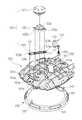
도 4는 본 발명에 따른 증기배출 기능을 구비한 압력밥솥의 뚜껑 잠금장치를 도시한 분해 사시도로서, 도시된 바와 같이, 쌀 등의 조리물을 내부에 수용하는 밥솥 본체(미도시)의 개방된 상부를 개폐하도록 설치되는 뚜껑(100)의 일측에는 취사가 완료된 후, 밥솥 내부의 증기를 외부로 배출하기 위한 증기배출수단(110)이 마 련되어 있다. 여기서, 증기배출수단(110)은 밥솥 내부와 연통된 증기배출관(111) 및 증기배출관(111)의 개방된 상단을 개폐하기 위한 압력추(112)를 포함한다. 또한, 압력추(112)는 중앙에 증기배출관(111)의 개방된 상단에 얹혀 있는 추(112a; 도 7 및 도 8 참조)와, 증기배출관(111)의 외부를 감싸도록 형성된 우산형상의 덮개(112b; 도 7 및 도 8 참조)를 포함한다.Figure 4 is an exploded perspective view showing a lid lock of the pressure cooker having a steam discharge function according to the present invention, as shown, the open of the cooker body (not shown) for receiving food, such as rice therein On one side of the
본 발명에 따른 압력밥솥의 뚜껑 잠금장치는 뚜껑(100)의 잠금 및 해제 역할을 수행함과 더불어 상술한 증기배출수단(110)을 통해 밥솥 내부의 증기가 배출되도록 하는 역할을 수행하는 것으로서, 핸들 부재(120), 개폐링(130), 캠 부재(140), 및 레버 부재(150)를 포함한다.The lid locking device of the pressure cooker according to the present invention serves to lock and release the
핸들 부재(120)는 원통 형상의 핸들(121)과, 핸들(121)의 하부에 결합되며 저면으로부터 하방으로 돌출된 3개의 레버(122a, 122b, 122c)를 구비한 핸들 샤프트(122), 및 핸들 샤프트(122)의 3개의 레버(122a, 122b, 122c)가 각각 삽입되도록 3개의 통공(123a, 123b, 123c)을 형성한 핸들 가이드(123)를 포함한다.The
이 핸들 부재(120)가 장착되는 뚜껑 부분에는 핸들 샤프트(122)의 중앙측 레버(122a)가 삽입되는 삽입공(101a)이 형성되어 있다.An
또한, 이 삽입공(101a)의 주변에는 서로 대칭되도록 2개의 원호 형상의 삽입공(101b, 101c)이 형성되어 중앙측 레버(122a)를 제외한 2개의 레버(122b, 122c)가 각각 삽입되어 회동되도록 되어 있다. 한편, 뚜껑(100)의 전방측에는 또 하나의 원호형상의 삽입공(101d)이 형성되어 후술되는 개폐링(130)이 핸들 부재(120)와 연동되도록 한다.In addition, two circular arc-
개폐링(130)은 뚜껑(100)의 하부에 장착되며, 원주방향으로 서로 일정간격 이격되어 다수의 결합공(131)이 형성되어 있으며, 도면에 도시하진 않았지만, 이 결합공(131)들은 밥솥 본체에 형성되어 있는 결합돌기들과 결합 또는 해체되어 뚜껑과 밥솥 본체의 잠금 및 잠금 해제 상태를 만들어 준다.Opening and
또한, 개폐링(130)에 일측에는 원호형상의 삽입공(101d)에 삽입되는 회동 레버(132)가 형성되어 있다. 이 회동 레버(132)로 인해, 핸들(121)이 일방향으로 회전되면 핸들 샤프트(122)에 구비된 레버들(122b, 122c)의 회동에 의해 핸들 가이드(123)가 회동되고, 핸들 가이드(123)의 회동에 의해 개폐링(130)의 회동 레버(132)가 회동하게 되어, 개폐링(130)이 회동하게 된다.In addition, on one side of the opening and
한편, 캠 부재(140)는 개폐링(130)의 후방측 내주연에 장착되며, 개폐링(130)의 회동방향과 대향하는 경사면(141)을 구비한다. 구체적으로, 경사면(141)은 개폐링(130)의 회동방향을 따라 일정각도 기울어져 있으며, 이 경사면(141)을 따라 후술되는 레버 부재(150)가 상하방향으로 운동하게 된다.On the other hand, the
레버 부재(150)는 개폐링(130)의 회동에 따라 캠 부재(140)와 연동되어 밥솥 내부의 증기가 외부로 배출되도록 증기배출수단(110)을 개방하게 된다.The
구체적으로, 레버 부재(150)는 연동 레버(151)와 작동 레버(152)로 이루어진다.Specifically, the
연동 레버(151)는 일측이 뚜껑(100)에 회동 가능하게 뚜껑(100)에 힌지(151a)로 결합되고, 타측이 캠 부재(140)의 경사면(141)과 접하도록 형성되어, 개폐링(130)의 회동에 의해 캠 부재(140)가 회동하게 되면, 캠 부재(140)의 회동에 의해 상하방향으로 운동하게 된다.The interlocking
여기서, 연동 레버(151)는 하면이 캠 부재(140)의 경사면(141)과 접하고, 상면이 작동 레버(152)의 하단부를 상방향으로 가압하도록 절곡되어 돌출되어 있다.Here, the
작동 레버(152)는 연동 레버(151)의 상하방향 운동에 의해 증기배출수단(110)의 압력추(112)를 들어올리게 된다. 구체적으로, 작동 레버(152)는 하측이 연동 레버(151)와 접촉되어 있고, 상측이 압력추(112)의 덮개(112b) 하단에 인접하게 설치되며, 뚜껑(100)에 상하방향으로 형성되어 있는 슬라이딩홈(미도시) 내부에 슬라이딩 가능하게 장착되어, 연동 레버(151)의 상하방향 운동에 의해 상하방향으로 슬라이딩하게 된다.The
이와 같이, 본 발명은 핸들 부재(120)의 회동에 의해 증기가 배출되도록 작동하는 레버 부재(150)가 뚜껑(100)에 수직방향으로 설치되기 때문에, 기존의 수평방향으로 설치되는 경우보다 설치공간의 제약을 받지 않으며, 이에 따라 제품 설계시, 다양한 설계 변형이 가능하다.As such, the present invention is installed because the
도 5는 본 발명의 제 1 실시예에 따른 작동 레버를 확대 도시한 사시도로서, 도시된 바와 같이, 작동 레버(152)는 중앙 상면에 삽입홈(153a)이 형성되고, 하단부가 연동 레버(151)와 접하여 연동 레버(151)의 상하방향 운동에 따라 상하방향으로 슬라이딩홈 내부를 슬라이딩하는 몸체(153)와, 일측이 몸체(153)의 삽입홈(153a)에 삽입되고 타측이 압력추(112)의 덮개(112b)를 향하도록 연장되어, 연동 레버(151)의 상방향 운동에 의해 압력추(112)의 덮개(112b)를 들어올리는 막대 형상의 가압부(154), 및 가압부(154)가 몸체(153)에 고정되도록 삽입홈(153a)의 하측 으로부터 삽입되어 몸체(153)와 가압부(154)를 체결하는 스크류 등의 체결부재(155)를 포함한다.5 is an enlarged perspective view of the operation lever according to the first embodiment of the present invention. As shown in the drawing, the
또한, 가압부(154)의 상단부에는 그 외경방향으로 연장된 플랜지(154a)가 형성되어, 작동 레버(152)가 증기배출관(111)에 인접하게 설치되어 있지 않아도, 증기배출수단의 덮개(112b)를 상방향으로 들어올릴 수 있다.In addition, a
이때, 가압부(154)의 외주연을 둘러싸도록 몸체(153)의 삽입홈(153a) 상단에 코일 스프링(156)이 설치되어 있다.At this time, the
따라서, 개폐링(130)의 회동에 의해 연동 레버(151)가 회동하게 되면, 연동 레버(151)에 의해 작동 레버(152)를 구성하는 몸체(153), 가압부(154), 및 체결부재(155)가 일체로 상하방향으로 운동하게 되어 증기배출수단(110)의 덮개(112b)를 들어올리게 된다.Therefore, when the interlocking
도 6은 본 발명의 제 2 실시예에 따른 작동 레버를 확대 도시한 사시도로서, 도시된 바와 같이, 작동 레버(152')는 뚜껑에 고정되고, 중앙에 상하방향으로 관통공(153a')이 형성되어 있는 몸체(153'), 및 몸체(153')의 관통공(153a')을 따라 상하방향으로 슬라이딩 가능하게 삽입되고, 하단이 연동 레버와 접하며, 상단이 압력추의 덮개를 향하도록 연장되어 있는 막대 형상의 가압부(154')를 포함한다.6 is an enlarged perspective view of the operation lever according to the second embodiment of the present invention. As shown in the drawing, the operation lever 152 'is fixed to the lid, and the through
이때, 관통공(153a')의 상단에 고정되고, 가압부(154')의 외주연을 둘러싸도록 코일 스프링(156')이 설치되어, 가압부(154')가 몸체(153')에 고정되어 상하방향으로 슬라이딩되도록 한다.At this time, the coil spring 156 'is fixed to the upper end of the through
또한, 가압부(154')의 상단부에는 그 외경방향으로 연장된 플랜지(154a')가 형성되어, 작동 레버(152')가 증기배출관에 인접하게 설치되어 있지 않아도, 증기배출수단(110)의 덮개(112b)를 상방향으로 들어올릴 수 있다.In addition, a
따라서, 개폐링(130)의 회동에 의해 연동 레버(151)가 회동하게 되면, 연동 레버(151)에 의해 작동 레버(152')의 가압부(154') 하단이 상방으로 가압되어 가압부(154')의 상단이 증기배출수단(110)의 덮개(112b)를 들어올리게 된다.Therefore, when the interlocking
이하, 첨부된 도면을 참조하여 본 발명의 제 1실시예에 따른 전기압력밥솥의 뚜껑 잠금장치의 작동상태를 설명한다. 여기서, 본 발명의 제 2 실시예는 제 1 실시예와 실질적으로 동일하게 작동하므로, 제 1 실시예의 작동 상태만을 설명한다.Hereinafter, with reference to the accompanying drawings will be described the operating state of the lid locking device of the electric pressure cooker according to the first embodiment of the present invention. Here, since the second embodiment of the present invention operates substantially the same as the first embodiment, only the operating state of the first embodiment will be described.
도 7은 뚜껑 잠금시의 작동상태를 측면에서 도시한 도면이고, 도 8은 뚜껑 잠금 해제시의 작동상태를 측면에서 도시한 도면으로서, 도 4, 도 5, 도 7, 및 도 8을 참조하여 설명한다.Figure 7 is a view showing the operating state when the lid is locked from the side, Figure 8 is a view showing the operating state when the lid is unlocked, with reference to Figures 4, 5, 7, and 8. Explain.
먼저, 뚜껑(100)의 잠금 상태가 해제되도록 압력밥솥의 뚜껑 상측에 구비된 핸들 부재(120)를 일방향으로 회동시키면, 회동 레버(132)의 회동에 의해 개폐링(130)이 회동하게 된다.First, when the
이와 동시에 개폐링(130)에 설치된 캠 부재(140)가 일방향으로 회동하면서, 캠 부재(140)의 경사면(141)과 접해 있던 연동 레버(151)가 일정높이 상승하게 된다.At the same time, as the
이어서, 연동 레버(151)와 접해 있던 작동 레버(152)의 가압부(154)가 상방향으로 슬라이딩됨과 동시에, 가압부(154)의 상단이 증기배출수단(110)의 덮 개(112b)를 밀어올려 증기배출관(111)이 개방된다.Subsequently, while the
따라서, 뚜껑(100)의 잠금 해제와 동시에 증기배출관(111)이 개방되어 밥솥 내부에 있던 증기가 외부로 배출된다.Therefore, the
한편, 뚜껑(100)이 잠금 상태가 되도록 압력밥솥의 뚜껑(100) 상측에 구비된 핸들 부재(120)를 상기 해제 방향과는 반대방향(타방향)으로 회동시키면, 회동 레버(132)의 회동에 의해 개폐링(130)이 타방향으로 회동하게 된다.On the other hand, when the
이와 동시에 개폐링(130)에 설치된 캠 부재(140)가 타방향으로 회동하면서, 캠 부재(140)의 경사면(141)과 접해 있던 연동 레버(151)가 일정높이 하강하게 된다.At the same time, as the
이어서, 연동 레버(151)와 접해 있던 작동 레버(152)의 가압부(154)가 하방향으로 슬라이딩됨과 동시에, 가압부(154)의 상단이 증기배출수단(110)의 덮개(112b)로부터 하측으로 이격되어 증기배출관(11)이 다시 압력추(112)에 의해 폐쇄된다.Subsequently, while the
따라서, 뚜껑(100)의 잠금과 동시에 증기배출관(111)이 폐쇄되어, 밥솥 내부의 증기가 더 이상 외부로 배출되지 않는다.Therefore, the
상술한 바와 같이, 본 발명에 따른 증기배출 기능을 구비한 압력밥솥의 뚜껑 잠금 장치는 핸들 부재와 연동되는 개폐링 및 레버 부재에 의해 뚜껑의 잠금 동작과 동시에 밥솥 내부의 증기가 배출되도록 할 수 있는 효과가 있다.As described above, the lid lock device of the pressure cooker having a steam discharge function according to the present invention is capable of allowing the steam inside the cooker to be discharged at the same time as the locking operation of the lid by the opening and closing ring and the lever member interlocked with the handle member. It works.
또한, 본 발명은 증기 배출을 위해 뚜껑에 설치되는 레버 부재가 수직방향으로 설치되어 연동되기 때문에, 설치공간의 제약을 해소할 수 있는 효과가 있다.In addition, the present invention because the lever member is installed in the vertical direction is interlocked with the lid for steam discharge, there is an effect that can be eliminated the constraint of the installation space.
또한, 설치공간의 제약을 해소함으로써, 제품의 설계 자유도를 향상시킬 수 있는 효과가 있다.In addition, by eliminating the limitation of the installation space, there is an effect that can improve the design freedom of the product.
이상에서는, 본 발명을 특정의 바람직한 실시 예에 대해서 도시하고 설명하였다. 그러나, 본 발명은 상술한 실시 예에만 한정되는 것이 아니며, 본 발명이 속하는 기술 분야에서 통상의 지식을 가진 자라면 이하의 특허청구범위에 기재된 본 발명의 기술적 사상의 요지를 벗어남이 없이 얼마든지 다양하게 변경 실시할 수 있을 것이다.In the above, the present invention has been shown and described with respect to certain preferred embodiments. However, the present invention is not limited only to the above-described embodiments, and those skilled in the art to which the present invention pertains may vary without departing from the spirit of the technical idea of the present invention described in the claims below. It will be possible to carry out the change.
Claims (6)
Translated fromKoreanPriority Applications (1)
| Application Number | Priority Date | Filing Date | Title |
|---|---|---|---|
| KR1020070064190AKR20090002411A (en) | 2007-06-28 | 2007-06-28 | Lid lock of pressure cooker with steam discharge function |
Applications Claiming Priority (1)
| Application Number | Priority Date | Filing Date | Title |
|---|---|---|---|
| KR1020070064190AKR20090002411A (en) | 2007-06-28 | 2007-06-28 | Lid lock of pressure cooker with steam discharge function |
Publications (1)
| Publication Number | Publication Date |
|---|---|
| KR20090002411Atrue KR20090002411A (en) | 2009-01-09 |
Family
ID=40485409
Family Applications (1)
| Application Number | Title | Priority Date | Filing Date |
|---|---|---|---|
| KR1020070064190ACeasedKR20090002411A (en) | 2007-06-28 | 2007-06-28 | Lid lock of pressure cooker with steam discharge function |
Country Status (1)
| Country | Link |
|---|---|
| KR (1) | KR20090002411A (en) |
Cited By (11)
| Publication number | Priority date | Publication date | Assignee | Title |
|---|---|---|---|---|
| KR200459784Y1 (en)* | 2009-12-23 | 2012-04-18 | (주)네오플램 | Apparatus of steam hole assembly having multi-type steam hole and inclined fluid path and The cooking utensils thereof |
| CN106108630A (en)* | 2016-09-19 | 2016-11-16 | 珠海格力电器股份有限公司 | Electric pressure cooker and cooker cover assembly thereof |
| CN106213986A (en)* | 2016-09-19 | 2016-12-14 | 珠海格力电器股份有限公司 | Electric pressure cooker and cooker cover assembly thereof |
| CN106923655A (en)* | 2017-01-21 | 2017-07-07 | 九阳股份有限公司 | A kind of electric pressure cooking saucepan conveniently uncapped |
| KR20190043950A (en)* | 2017-10-19 | 2019-04-29 | 쿠쿠전자 주식회사 | electric cooker and apparatus for removing remain pressure thereof |
| CN110840266A (en)* | 2019-11-26 | 2020-02-28 | 珠海格力电器股份有限公司 | Circuit wiring structure for portable maintenance and installation of display panel assembly and installation method |
| CN113208439A (en)* | 2020-01-21 | 2021-08-06 | 浙江苏泊尔家电制造有限公司 | Cooking utensil |
| KR102418397B1 (en)* | 2021-06-14 | 2022-07-08 | (주)쿠첸 | Cooking apparatus |
| KR102418398B1 (en)* | 2021-06-14 | 2022-07-08 | (주)쿠첸 | Cooking apparatus |
| CN115381279A (en)* | 2017-09-08 | 2022-11-25 | 福库电子株式会社 | Electric cooking device |
| US12318031B2 (en) | 2021-06-14 | 2025-06-03 | Cuchen Co., Ltd | Cooking device |
- 2007
- 2007-06-28KRKR1020070064190Apatent/KR20090002411A/ennot_activeCeased
Cited By (12)
| Publication number | Priority date | Publication date | Assignee | Title |
|---|---|---|---|---|
| KR200459784Y1 (en)* | 2009-12-23 | 2012-04-18 | (주)네오플램 | Apparatus of steam hole assembly having multi-type steam hole and inclined fluid path and The cooking utensils thereof |
| CN106108630A (en)* | 2016-09-19 | 2016-11-16 | 珠海格力电器股份有限公司 | Electric pressure cooker and cooker cover assembly thereof |
| CN106213986A (en)* | 2016-09-19 | 2016-12-14 | 珠海格力电器股份有限公司 | Electric pressure cooker and cooker cover assembly thereof |
| CN106923655A (en)* | 2017-01-21 | 2017-07-07 | 九阳股份有限公司 | A kind of electric pressure cooking saucepan conveniently uncapped |
| CN106923655B (en)* | 2017-01-21 | 2020-10-02 | 九阳股份有限公司 | Electric pressure cooker convenient to open cover |
| CN115381279A (en)* | 2017-09-08 | 2022-11-25 | 福库电子株式会社 | Electric cooking device |
| KR20190043950A (en)* | 2017-10-19 | 2019-04-29 | 쿠쿠전자 주식회사 | electric cooker and apparatus for removing remain pressure thereof |
| CN110840266A (en)* | 2019-11-26 | 2020-02-28 | 珠海格力电器股份有限公司 | Circuit wiring structure for portable maintenance and installation of display panel assembly and installation method |
| CN113208439A (en)* | 2020-01-21 | 2021-08-06 | 浙江苏泊尔家电制造有限公司 | Cooking utensil |
| KR102418397B1 (en)* | 2021-06-14 | 2022-07-08 | (주)쿠첸 | Cooking apparatus |
| KR102418398B1 (en)* | 2021-06-14 | 2022-07-08 | (주)쿠첸 | Cooking apparatus |
| US12318031B2 (en) | 2021-06-14 | 2025-06-03 | Cuchen Co., Ltd | Cooking device |
Similar Documents
| Publication | Publication Date | Title |
|---|---|---|
| KR20090002411A (en) | Lid lock of pressure cooker with steam discharge function | |
| US12089768B2 (en) | Electric cooking appliance provided with a removable heating device | |
| US20180296020A1 (en) | Pressure Cooker | |
| JP5745428B2 (en) | Pressure cooker | |
| US20140013960A1 (en) | Cooking Utensil for Cooking Food Under Pressure that has an Improved Control Device | |
| US7090094B2 (en) | Handle for cookware | |
| JP2021006251A (en) | Cooking appliance for cooking food with or without pressure | |
| JP5864538B2 (en) | Utensil for cooking food under pressure comprising a selector and a pressure management member | |
| JP2008048767A (en) | Pressure cooker | |
| WO2007140547A1 (en) | Cooking press and grill | |
| US20160120369A1 (en) | Kitchen appliance comprising positioning device | |
| KR20140142086A (en) | Stone kettle pressure receptacle | |
| KR20110083850A (en) | electric rice cooker | |
| KR100736780B1 (en) | Safety device of electric pressure cooker | |
| KR200383385Y1 (en) | Lock system for pressure rice pot | |
| KR200366233Y1 (en) | A doubleness lock device of the electricity pressure rice kettle | |
| CN217013655U (en) | Baking tray device with adjustable angle | |
| JP2008011889A (en) | rice cooker | |
| JP2024162826A (en) | Cooking equipment | |
| JPS5843684Y2 (en) | heating cooker | |
| JP2024162823A (en) | Cooking equipment | |
| JP2016073349A (en) | Vacuum release device of vacuum-inducted cooking pot | |
| JP2024162822A (en) | Cooking equipment | |
| KR100579047B1 (en) | Safety device of electric pressure cooker | |
| JP7493112B2 (en) | Cooking equipment |
Legal Events
| Date | Code | Title | Description |
|---|---|---|---|
| A201 | Request for examination | ||
| PA0109 | Patent application | Patent event code:PA01091R01D Comment text:Patent Application Patent event date:20070628 | |
| PA0201 | Request for examination | ||
| E902 | Notification of reason for refusal | ||
| PE0902 | Notice of grounds for rejection | Comment text:Notification of reason for refusal Patent event date:20081030 Patent event code:PE09021S01D | |
| PG1501 | Laying open of application | ||
| E902 | Notification of reason for refusal | ||
| PE0902 | Notice of grounds for rejection | Comment text:Notification of reason for refusal Patent event date:20090409 Patent event code:PE09021S01D | |
| E601 | Decision to refuse application | ||
| PE0601 | Decision on rejection of patent | Patent event date:20090701 Comment text:Decision to Refuse Application Patent event code:PE06012S01D Patent event date:20090409 Comment text:Notification of reason for refusal Patent event code:PE06011S01I Patent event date:20081030 Comment text:Notification of reason for refusal Patent event code:PE06011S01I |