KR20080109890A - Electronic tag - Google Patents
Electronic tagDownload PDFInfo
- Publication number
- KR20080109890A KR20080109890AKR1020087026370AKR20087026370AKR20080109890AKR 20080109890 AKR20080109890 AKR 20080109890AKR 1020087026370 AKR1020087026370 AKR 1020087026370AKR 20087026370 AKR20087026370 AKR 20087026370AKR 20080109890 AKR20080109890 AKR 20080109890A
- Authority
- KR
- South Korea
- Prior art keywords
- tag
- contactless
- magnetic
- electronic tag
- antenna
- Prior art date
- Legal status (The legal status is an assumption and is not a legal conclusion. Google has not performed a legal analysis and makes no representation as to the accuracy of the status listed.)
- Granted
Links
Images


Classifications
- G—PHYSICS
- G06—COMPUTING OR CALCULATING; COUNTING
- G06K—GRAPHICAL DATA READING; PRESENTATION OF DATA; RECORD CARRIERS; HANDLING RECORD CARRIERS
- G06K19/00—Record carriers for use with machines and with at least a part designed to carry digital markings
- G06K19/06—Record carriers for use with machines and with at least a part designed to carry digital markings characterised by the kind of the digital marking, e.g. shape, nature, code
- G06K19/067—Record carriers with conductive marks, printed circuits or semiconductor circuit elements, e.g. credit or identity cards also with resonating or responding marks without active components
- G06K19/07—Record carriers with conductive marks, printed circuits or semiconductor circuit elements, e.g. credit or identity cards also with resonating or responding marks without active components with integrated circuit chips
- G06K19/077—Constructional details, e.g. mounting of circuits in the carrier
- G06K19/07749—Constructional details, e.g. mounting of circuits in the carrier the record carrier being capable of non-contact communication, e.g. constructional details of the antenna of a non-contact smart card
- G—PHYSICS
- G06—COMPUTING OR CALCULATING; COUNTING
- G06K—GRAPHICAL DATA READING; PRESENTATION OF DATA; RECORD CARRIERS; HANDLING RECORD CARRIERS
- G06K19/00—Record carriers for use with machines and with at least a part designed to carry digital markings
- G06K19/06—Record carriers for use with machines and with at least a part designed to carry digital markings characterised by the kind of the digital marking, e.g. shape, nature, code
- G06K19/067—Record carriers with conductive marks, printed circuits or semiconductor circuit elements, e.g. credit or identity cards also with resonating or responding marks without active components
- G06K19/07—Record carriers with conductive marks, printed circuits or semiconductor circuit elements, e.g. credit or identity cards also with resonating or responding marks without active components with integrated circuit chips
- G06K19/077—Constructional details, e.g. mounting of circuits in the carrier
- G—PHYSICS
- G06—COMPUTING OR CALCULATING; COUNTING
- G06K—GRAPHICAL DATA READING; PRESENTATION OF DATA; RECORD CARRIERS; HANDLING RECORD CARRIERS
- G06K19/00—Record carriers for use with machines and with at least a part designed to carry digital markings
- G06K19/06—Record carriers for use with machines and with at least a part designed to carry digital markings characterised by the kind of the digital marking, e.g. shape, nature, code
- G06K19/067—Record carriers with conductive marks, printed circuits or semiconductor circuit elements, e.g. credit or identity cards also with resonating or responding marks without active components
- G06K19/07—Record carriers with conductive marks, printed circuits or semiconductor circuit elements, e.g. credit or identity cards also with resonating or responding marks without active components with integrated circuit chips
- G06K19/077—Constructional details, e.g. mounting of circuits in the carrier
- G06K19/07749—Constructional details, e.g. mounting of circuits in the carrier the record carrier being capable of non-contact communication, e.g. constructional details of the antenna of a non-contact smart card
- G06K19/0775—Constructional details, e.g. mounting of circuits in the carrier the record carrier being capable of non-contact communication, e.g. constructional details of the antenna of a non-contact smart card arrangements for connecting the integrated circuit to the antenna
- G06K19/07756—Constructional details, e.g. mounting of circuits in the carrier the record carrier being capable of non-contact communication, e.g. constructional details of the antenna of a non-contact smart card arrangements for connecting the integrated circuit to the antenna the connection being non-galvanic, e.g. capacitive
- G—PHYSICS
- G06—COMPUTING OR CALCULATING; COUNTING
- G06K—GRAPHICAL DATA READING; PRESENTATION OF DATA; RECORD CARRIERS; HANDLING RECORD CARRIERS
- G06K19/00—Record carriers for use with machines and with at least a part designed to carry digital markings
- G06K19/06—Record carriers for use with machines and with at least a part designed to carry digital markings characterised by the kind of the digital marking, e.g. shape, nature, code
- G06K19/067—Record carriers with conductive marks, printed circuits or semiconductor circuit elements, e.g. credit or identity cards also with resonating or responding marks without active components
- G06K19/07—Record carriers with conductive marks, printed circuits or semiconductor circuit elements, e.g. credit or identity cards also with resonating or responding marks without active components with integrated circuit chips
- G06K19/077—Constructional details, e.g. mounting of circuits in the carrier
- G06K19/07749—Constructional details, e.g. mounting of circuits in the carrier the record carrier being capable of non-contact communication, e.g. constructional details of the antenna of a non-contact smart card
- G06K19/07758—Constructional details, e.g. mounting of circuits in the carrier the record carrier being capable of non-contact communication, e.g. constructional details of the antenna of a non-contact smart card arrangements for adhering the record carrier to further objects or living beings, functioning as an identification tag
- G06K19/0776—Constructional details, e.g. mounting of circuits in the carrier the record carrier being capable of non-contact communication, e.g. constructional details of the antenna of a non-contact smart card arrangements for adhering the record carrier to further objects or living beings, functioning as an identification tag the adhering arrangement being a layer of adhesive, so that the record carrier can function as a sticker
- H—ELECTRICITY
- H04—ELECTRIC COMMUNICATION TECHNIQUE
- H04B—TRANSMISSION
- H04B1/00—Details of transmission systems, not covered by a single one of groups H04B3/00 - H04B13/00; Details of transmission systems not characterised by the medium used for transmission
- H04B1/59—Responders; Transponders
- H—ELECTRICITY
- H04—ELECTRIC COMMUNICATION TECHNIQUE
- H04B—TRANSMISSION
- H04B5/00—Near-field transmission systems, e.g. inductive or capacitive transmission systems
- H04B5/40—Near-field transmission systems, e.g. inductive or capacitive transmission systems characterised by components specially adapted for near-field transmission
- H04B5/48—Transceivers
Landscapes
- Engineering & Computer Science (AREA)
- Microelectronics & Electronic Packaging (AREA)
- Computer Hardware Design (AREA)
- Physics & Mathematics (AREA)
- General Physics & Mathematics (AREA)
- Theoretical Computer Science (AREA)
- Computer Networks & Wireless Communication (AREA)
- Signal Processing (AREA)
- Burglar Alarm Systems (AREA)
Abstract
Translated fromKoreanDescription
Translated fromKorean본 발명은, 비접촉식 IC 태그와 자기식 태그가 일체화된 전자 태그로서, 개체 식별 및 도난 방지의 양쪽의 기능을 겸비한 전자 태그에 관한 것이다.BACKGROUND OF THE
최근,비접촉식 IC 태그를 이용하는 비접촉식 개체 식별 시스템은, 생산품의 라이프 사이클 전체를 관리하는 시스템으로서, 제조, 물류, 판매, 리사이클의 모든 업태에서 주목받고 있다. 특히 UHF파나 마이크로파를 이용하는 전파 방식의 비접촉식 IC 태그는, IC칩에 외부 안테나를 부착한 구조로 수 미터의 통신 거리가 가능하다고 하는 특징에 의해 주목받고 있으며, 현재, 대량 상품의 물류 관리나 제조 물 이력 관리, 시큐러티 관리 등을 목적으로 시스템의 구축이 진행되고 있다.In recent years, a contactless individual identification system using a contactless IC tag has attracted attention in all aspects of manufacturing, logistics, sales, and recycling as a system for managing the entire life cycle of a product. In particular, radio wave contactless IC tags using UHF waves or microwaves are attracting attention due to the feature that an external antenna is attached to the IC chip, which enables communication distances of several meters. The system is being built for the purpose of history management and security management.
한편,자기식 태그는, 자성체가 전자장에 영향을 미치는 것을 이용하여, 점포로부터의 상품의 부정한 반출을 방지하는 등을 위해 이용되고 있다. 자기식 태그는, 전자장을 발생 및 감지하는 게이트 등의 시스템과 대응시켜서 이용되고 있지만, 개별 물품마다의 식별 기능은 없기 때문에, 어디까지나 상품의 점포로부터의 부정한 반출을 감시하는 등의 시스템으로서, 재고 조사 등의 상품 관리를 하는 데에는 이용할 수 없는 것이었다. 전자 태그로 도난 방지와 상품 관리의 양쪽을 행하고자 하는 경우에는, 자기식 태그와 비접촉식 IC 태그를 따로따로 상품에 부착하 는 것으로 가능하게 되지만, 부착하는 수고와 양쪽의 태그의 비용이 들고 있었다.On the other hand, magnetic tags are used for preventing the unfair take-out of goods from a store by using a magnetic material that affects an electromagnetic field. Magnetic tags are used in correspondence with systems such as gates that generate and detect electromagnetic fields, but because they do not have an identification function for each individual item, they are stocked as a system for monitoring illegal release from stores of goods to the last. It was not available for product management such as investigation. In the case where both the anti-theft and product management are to be performed with the electronic tag, it is possible to attach the magnetic tag and the non-contact IC tag separately to the product, but the labor of attaching the tag and the cost of both tags are incurred.
따라서,도난 방지와 상품 관리의 양쪽의 기능을 겸비한 전자 태그가, 특허 공개 2004-4227508호 공보에서 고안되어 있다. 이 전자 태그는, 무선 IC칩을 내장한 케이스 태그 본체에 연자성체의 박층이 형성되고, 안테나용으로서 연자성체로 이루어지는 금속선을 맞붙인 현수지지용 코드가 부착된 구조를 하고 있다. 이 전자 태그는, 연자성체의 박층과 무선 IC칩을 어긋나게 하여 동일 케이스 내에 팩되어 있으며, 현수지지용 코드를 구비하고,상품의 외측에 부착하는 형상을 하고 있다.Therefore, an electronic tag having both functions of anti-theft and product management is devised in Japanese Patent Laid-Open No. 2004-4227508. The electronic tag has a structure in which a thin layer of a soft magnetic material is formed on a case tag main body in which a wireless IC chip is embedded, and a suspension support cord is bonded to a metal wire made of a soft magnetic material for antenna use. This electronic tag is packed in the same case by shifting a thin layer of a soft magnetic material and a wireless IC chip, and is provided with a suspension support cord and is attached to the outside of a product.
그러나, 상품에 따라서는, 전자 태그가 상품과 거의 일체화되는 형상인 것이 요구되는 경우가 있다. 예를 들면, 상품이 서적, CD, DVD 등의 경우, 선반에 진열된 상태 그대로 재고를 확인할 수 있도록 하기 위해서는, 등표지나 케이스의 폭이 좁은 면에 전자 태그를 접착할 필요가 있다.However, depending on the product, it may be required that the electronic tag be in a shape that is almost integrated with the product. For example, if a product is a book, CD, DVD or the like, in order to be able to check the stock as it is displayed on the shelf, it is necessary to adhere the electronic tag to the narrow surface of the back cover or the case.
이와 같은 경우, 전자 태그는 가늘고, 얇은 형상인 것이 필수적이다. 또한 저가격으로 하기 위해서는 소형인 것이 요망된다.In such a case, it is essential that the electronic tag is thin and thin in shape. In addition, it is desired to be small in order to achieve a low price.
<발명의 개시><Start of invention>
본 발명은, 전술한 실정을 감안하여, 도난 방지와 상품 관리의 양쪽의 기능을 겸비하고, 또한, 피착체에 부착하는 수고를 경감할 수 있고, 게다가 세형이며 염가의 전자 태그를 제공하는 것을 목적으로 하고 있다.SUMMARY OF THE INVENTION In view of the above-described circumstances, the present invention combines the functions of both anti-theft and merchandise management, and can reduce the effort of attaching to an adherend, and further provides a thin and inexpensive electronic tag. I am doing it.
전술한 과제를 해결하기 위하여, 본 발명에 따른 전자 태그는, 개체 식별 정보를 갖는 IC칩과 송수신 안테나를 포함하는 비접촉식 IC 태그와, 자기식 태그를 포함하고,상기 비접촉식 IC 태그와 상기 자기식 태그가 적어도 일부분에서 절연층을 개재하여 겹쳐 있는 것이다.In order to solve the above-mentioned problems, the electronic tag according to the present invention includes a non-contact IC tag including an IC chip having an object identification information and a transmitting and receiving antenna, and a magnetic tag, and the non-contact IC tag and the magnetic tag Is overlapped at least in part via an insulating layer.
상기 전자 태그에서, 상기 자기식 태그의 자성 부분이 상기 비접촉 IC 태그에 이용하는 전파 주파수에서 전기 전도성을 갖고 있는 것이 바람직하다.In the electronic tag, it is preferable that the magnetic portion of the magnetic tag has electrical conductivity at a radio frequency used for the non-contact IC tag.
상기 전자 태그에서, 상기 비접촉식 IC 태그의 송수신 안테나가 비자성 재료로 구성되는 것이 바람직하다.In the electronic tag, it is preferable that the transmit / receive antenna of the contactless IC tag is made of a nonmagnetic material.
상기 전자 태그에서, 상기 비접촉식 IC 태그의 상기 송수신 안테나가, 알루미늄 또는 구리를 함유하는 것이 바람직하다.In the electronic tag, it is preferable that the transmission / reception antenna of the contactless IC tag contains aluminum or copper.
상기 전자 태그에서, 상기 비접촉식 IC 태그의 적어도 임피던스 정합 회로 부분이, 상기 자기식 태그의 자성 부분과 겹치지 않는 것이 바람직하다.In the electronic tag, it is preferable that at least the impedance matching circuit portion of the contactless IC tag does not overlap with the magnetic portion of the magnetic tag.
상기 전자 태그에서, 상기 자기식 태그의 상기 자성 부분의 길이가, 상기 비접촉식 IC 태그의 상기 송수신 안테나의 길이보다 긴 것이 바람직하다.In the electronic tag, the length of the magnetic portion of the magnetic tag is preferably longer than the length of the transmit / receive antenna of the contactless IC tag.
상기 전자 태그에서, 상기 비접촉식 IC 태그의 중심과, 상기 자기식 태그의 한쪽의 단부와의 거리가 20㎜ 내지 50㎜의 범위인 것이 바람직하다.In the electronic tag, it is preferable that the distance between the center of the contactless IC tag and one end of the magnetic tag is in the range of 20 mm to 50 mm.
상기 전자 태그에서, 상기 비접촉식 IC 태그의 동작 주파수가 400㎒ 이상인 것이 바람직하다.In the electronic tag, the operating frequency of the contactless IC tag is preferably 400 MHz or more.
상기 전자 태그에서, 상기 비접촉식 IC 태그의 길이가 30㎜ 이하인 것이 바람직하다.In the electronic tag, the length of the contactless IC tag is preferably 30 mm or less.
상기 전자 태그에서, 상기 비접촉식 IC 태그의 칩의 개체 식별 정보가 ROM에 의해 구성되어 있는 것이 바람직하다.In the electronic tag, it is preferable that the individual identification information of the chip of the contactless IC tag is configured by the ROM.
본 발명의 전자 태그는, 무선 통신용 IC칩과, 송수신 안테나로 이루어지는 비접촉식 IC 태그와, 자기식 태그를 포함함으로써, 도난 방지와 상품 관리의 양쪽의 기능을 겸비하고, 또한, 피착체에 부착하는 수고를 경감할 수 있고, 게다가 세형이며 염가의 전자 태그를 실현할 수 있다.The electronic tag of the present invention includes both a non-contact IC tag composed of a wireless communication IC chip, a transmission / reception antenna, and a magnetic tag, thereby serving as both an anti-theft and product management function, and also attaching to an adherend. In addition, it is possible to realize a thin and inexpensive electronic tag.
도 1의 (a)는 본 발명의 전자 태그의 형태의 일례를 나타내는 평면도이며, 도 1의 (b)는 본 발명의 전자 태그의 형태의 일례를 나타내는 단면도.Fig. 1A is a plan view showing an example of the form of the electronic tag of the present invention, and Fig. 1B is a cross-sectional view showing an example of the form of the electronic tag of the present invention.
도 2의 (a)는 비접촉식 IC 태그의 형태의 일례를 나타내는 평면도이며, 도 2 의 (b)는 비접촉식 IC 태그의 형태의 일례를 나타내는 평면도.FIG. 2A is a plan view illustrating an example of a form of a noncontact IC tag, and FIG. 2B is a plan view illustrating an example of a form of a noncontact IC tag.
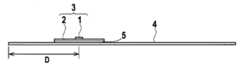
도 3은, 비접촉식 IC 태그 중심과, 자기식 태그의 한쪽의 단부와의 거리를 나타내는 단면도.3 is a cross-sectional view showing a distance between a contactless IC tag center and one end of a magnetic tag.
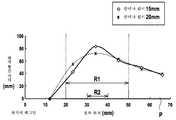
도 4는, 본 발명의 전자 태그에 이용한 비접촉식 IC 태그의 중심과, 자기식 태그의 한쪽의 단부와의 거리와 비접촉식 IC 태그의 최대 통신 거리의 관계를 나타낸 그래프.Fig. 4 is a graph showing the relationship between the center of a contactless IC tag used for the electronic tag of the present invention, the distance between one end of the magnetic tag, and the maximum communication distance of the contactless IC tag.
<발명을 실시하기 위한 최량의 형태><Best Mode for Carrying Out the Invention>
이하, 본 발명의 실시 형태에 대하여 도면을 이용하여 상세히 설명한다. 또한,이하의 실시 형태는 예로서 나타내는 것으로, 본 발명은 이들의 실시 형태에 한정되는 것은 아니다.EMBODIMENT OF THE INVENTION Hereinafter, embodiment of this invention is described in detail using drawing. In addition, the following embodiment is shown as an example and this invention is not limited to these embodiment.
도 1에, 본 발명의 전자 태그의 형태의 일례를 나타낸다.An example of the form of the electronic tag of this invention is shown in FIG.
도 1의 (a)는 전자 태그의 평면도이며, 도 1의 (b)는 그 단면도이다. 본 형 태의 전자 태그는, 무선 통신용 IC칩(1)과 상기 IC칩(1)이 전기적으로 접속된 송수신 안테나(2)로 이루어지는 비접촉식 IC 태그(3)를, 점착층(5)을 개재하여 자기식 태그(4)에 겹친 구조이다.FIG. 1A is a plan view of an electronic tag, and FIG. 1B is a sectional view thereof. The electronic tag of this type uses a
도 2에, 본 발명의 바람직한 비접촉식 IC 태그의 일례를 나타낸다.2 shows an example of a preferred contactless IC tag of the present invention.
도 2의 (a) 및 도 2의 (b)는, 2.45㎓의 마이크로파를 이용하는 전파 방식의 비접촉식 IC 태그이다. 400㎒ 이상의 마이크로파를 이용하는 전파 방식의 비접촉식 IC 태그는, 안테나 형상이 막대 형상인 다이폴 안테나를 이용함으로써 양호한 통신 특성을 얻을 수 있기 때문에, 태그 형상의 세형화가 가능하다. 한편,동작 주파수가 13.56㎒인 전자 유도 방식의 비접촉식 IC 태그의 경우에는, 안테나가 코일 형상이기 때문에,어느 정도의 면적을 갖는 평판 형상으로 된다. 따라서,본 발명에 이용하는 비접촉식 IC 태그의 동작 주파수는, 400㎒ 이상인 것이 바람직하다.2 (a) and 2 (b) are radio wave contactless IC tags using a microwave of 2.45 GHz. Since the non-contact IC tag of the radio wave system using a microwave of 400 MHz or more can obtain a good communication characteristic by using the dipole antenna whose antenna shape is rod shape, the tag shape can be made thin. On the other hand, in the case of an electromagnetic induction type non-contact IC tag having an operating frequency of 13.56 MHz, since the antenna is coiled, it has a flat plate shape having a certain area. Therefore, the operating frequency of the contactless IC tag used in the present invention is preferably 400 MHz or more.
본 발명의 전자 태그에 이용하는 비접촉식 IC 태그는, 전파 방식의 비접촉식 IC 태그이며, 도 2에 도시한 바와 같이,송수신 안테나 기판에는 IC칩과의 임피던스 정합을 행하고, 양호한 통신 거리를 얻기 위한 L자형이나 T자형의 여진 슬릿(6)이 가공되어 있다. 본 발명의 전자 태그는, 이 여진 슬릿이 자기식 태그에 겹치지 않는 것이 바람직하다. 즉, 어떤 특정한 L자형이나 T자형의 여진 슬릿에서는, 표 1에 나타내는 바와 같이, 여진 슬릿이 자기식 태그와 겹친 경우, 임피던스 정합이취해지지 않게 되어, 비접촉식 IC 태그의 통신 성능이 저하하는 경우가 있기 때문이다. 원래, 자기식 태그와의 겹침을 고려한 여진 슬릿을 설계하는 경우를 제외하 고, 이와 같은 여진 슬릿의 겹침에 의한 비접촉식 IC 태그의 통신 성능의 저하가 일어나기 쉽다.The non-contact IC tag used for the electronic tag of the present invention is a radio wave type non-contact IC tag. As shown in Fig. 2, the transmit / receive antenna substrate has an L-shape for impedance matching with the IC chip to obtain a good communication distance. T-

또한,비접촉식 IC 태그의 송수신 안테나와 자기식 태그가 겹치지 않는 경우에도 통신 성능이 저하되는 경우가 있기 때문에, 비접촉식 IC 태그와 자기식 태그가 겹쳐 있는 구조가 바람직하다. 본 발명의 전자 태그는, 자기식 태그를 비접촉식 IC 태그의 부스터 안테나로서 이용하고 있다. 부스터 안테나란, 비접촉식 IC 태그의 통신 특성을 향상시키기 위해 설치되는 보조 안테나이다.In addition, even when the transmission / reception antenna of the contactless IC tag and the magnetic tag do not overlap, the communication performance may be deteriorated. Therefore, a structure in which the contactless IC tag and the magnetic tag overlap is preferable. In the electronic tag of the present invention, a magnetic tag is used as a booster antenna for a non-contact IC tag. The booster antenna is an auxiliary antenna provided to improve communication characteristics of the contactless IC tag.
일반적으로, 전파 방식에서 송수신 안테나 기판의 길이가 30㎜ 정도 이하인 비접촉식 IC 태그는, 단독으로는 통신 성능이 나쁘고, 판독성이 불안정하지만, 본 발명과 같이, 비접촉식 IC 태그와 자기식 태그를 절연층을 개재하여 겹침으로써, 고주파가 인가된 경우에, 비접촉식 IC 태그의 송수신 안테나와 자기식 태그가 전자 결합을 하고, 자기식 태그를 비접촉식 IC 태그의 부스터 안테나로서 이용할 수 있어, 통신 거리를 향상시킬 수 있다. 이와 같이, 자기식 태그를 부스터 안테나로서 이용함으로써, 비접촉식 IC 태그의 소형화, 저렴화가 실현 가능하다. 재료의 자원 절약화에 의해, 재료 제조나 가공에 따른 소비 에너지를 저감할 수 있다. 이것은, 제조로부터 이용, 폐기에 이르는 일련의 환경 부하(예를 들면 CO2 배출량)를 저감시키는 효과가 있다.In general, a contactless IC tag having a transmission / reception antenna substrate of about 30 mm or less in a radio wave method alone has poor communication performance and unstable readability. By overlapping through each other, when a high frequency is applied, the transmitting and receiving antenna of the contactless IC tag and the magnetic tag are electromagnetically coupled, and the magnetic tag can be used as a booster antenna of the contactless IC tag, thereby improving the communication distance. . In this way, by using the magnetic tag as the booster antenna, it is possible to reduce the size and cost of the non-contact IC tag. By saving the resources of the material, it is possible to reduce the energy consumption due to material production and processing. This has the effect of reducing a series of environmental loads (for example, CO2 emissions) from manufacture to use and disposal.
이와 같은 부스터 안테나 효과는, 비접촉식 IC 태그의 송수신 안테나의 일부와, 자기식 태그의 자성 부분의 일부가 겹쳐 있으면 충분하다. 단,그 효과를 크게 하기 위해서는, 하기가 충족되면 바람직한 경우가 있다.Such a booster antenna effect is sufficient if a part of the transmission / reception antenna of the contactless IC tag and a part of the magnetic part of the magnetic tag overlap. However, in order to enlarge the effect, when the following is satisfied, it may be preferable.
·자기식 태그의 자성 부분이, 비접촉식 IC 태그가 이용하는 전파의 주파수 대역에서 전기 전도성을 가질 것. 이것에 의해,자성 부분이 효과적으로 안테나 효과 내지 부스터 효과를 발휘한다.The magnetic part of the magnetic tag must have electrical conductivity in the frequency band of the radio waves used by the contactless IC tag. As a result, the magnetic portion effectively exhibits the antenna effect or the booster effect.
·자기식 태그의 자성 부분의 길이가, 비접촉식 IC 태그의 안테나 길이보다도 길 것. 이것에 의해,부스터 효과가 커지는 경우가 있다(단,짧더라도 효율적인 안테나의 설계가 가능하므로, 자성 부분의 길이의 장단에 구애받지 않는 경우도 있다).The length of the magnetic portion of the magnetic tag is longer than the antenna length of the non-contact IC tag. As a result, the booster effect may be increased (although it is possible to design an efficient antenna even if it is short, in some cases it is not limited to the length and length of the magnetic portion).
또한,비접촉식 IC 태그에 의해 자기식 태그의 성능을 열화시키지 않기 위해서는, 하기가 만족되면 바람직한 경우가 있다.In addition, in order not to deteriorate the performance of a magnetic tag by a contactless IC tag, it may be desirable if the following is satisfied.
·비접촉식 IC 태그의 송수신 안테나가 비자성 재료로 구성될 것. 이것에 의해,비접촉식 IC 태그가 자기적인 악영향을 미치지 않는다.The transmit / receive antenna of the contactless IC tag shall be made of nonmagnetic material. As a result, the contactless IC tag does not adversely affect magnetically.
비접촉식 IC 태그 자기식 태그의 배치는, 비접촉식 IC 태그의 동작 주파수를 2.45㎓로 한 경우, 비접촉식 IC 태그의 중심과 자기식 태그의 한쪽의 단부로부터의 거리가 20㎜∼50㎜의 범위에 있는 것이 바람직하다. 도 3에 양자의 배치의 설명도, 도 4에 양자의 배치와 최대 통신 거리의 관계를 나타낸다. 여기에서, 도 3에 비접촉식 IC 태그 중심-자기식 태그 단부간 거리 D를 나타낸다. 또한,도 4에 양호한 범위 R1 및 특히 양호한 범위 R2를 나타낸다. 비접촉식 IC 태그의 중심과 자기식 태그의 한쪽의 단부로부터의 거리가 30㎜∼40㎜일 때,가장 양호한 특성이 얻어지며, 특히 바람직한 배치이다.The arrangement of the non-contact IC tag magnetic tag is such that when the operating frequency of the non-contact IC tag is 2.45 kHz, the distance from the center of the non-contact IC tag and one end of the magnetic tag is in the range of 20 mm to 50 mm. desirable. The explanatory drawing of both arrangement | positioning in FIG. 3 shows the relationship of arrangement | positioning of both and a maximum communication distance in FIG. Here, FIG. 3 shows the distance D between the contactless IC tag center-magnetic tag ends. 4 shows a good range R1 and a particularly good range R2. When the distance from the center of the non-contact IC tag and one end of the magnetic tag is 30 mm to 40 mm, the best characteristics are obtained, which is a particularly preferred arrangement.
본 발명의 전자 태그에 이용하는 비접촉식 IC 태그의 송수신 안테나는, 알루미늄 또는 구리를 함유하는 금속을 이용할 수 있다. 이들 금속은 염가이고 에칭 등의 가공성도 좋으며, 양호한 특성을 얻기 위한 안테나 재료로서 일반적이어서, 바람직하다.As the transmission / reception antenna of the contactless IC tag used for the electronic tag of the present invention, a metal containing aluminum or copper can be used. These metals are inexpensive, have good workability such as etching, and are generally preferred as antenna materials for obtaining good characteristics.
또한,본 발명의 전자 태그에 이용하는 무선 통신용 IC칩은, 개체 식별 정보를 ROM에 의해 구성하는 것이 바람직하다. 무선 통신용 IC칩에 고유 ID만을 ROM에 의해 구성하고, 그 고유 ID를 네트워크상에서 관리하면, 소형이고 염가이면서, 또한 개찬(改竄) 불가능한 IC를 갖는 IC칩을 실현할 수 있기 때문이다. 이와 같은 IC칩은, 저렴하면서 높은 편리성을 갖기 때문에, 본 발명의 IC칩으로서 채용함으로써, 보다 큰 효과를 발휘할 수 있는 경우가 있다.Moreover, it is preferable that the IC chip for wireless communication used for the electronic tag of this invention comprises individual identification information by ROM. This is because an IC chip having a small, inexpensive, and irreversible IC can be realized if only a unique ID is configured by ROM in the wireless communication IC chip and the unique ID is managed on a network. Such an IC chip is inexpensive and has high convenience, so that a larger effect may be exhibited by employing it as the IC chip of the present invention.
본 발명의 무선 통신용 IC칩과 송수신 안테나로 이루어지는 비접촉식 IC 태그와 자기식 태그로 이루어지는 전자 태그는, 도난 방지와 상품 관리의 양쪽의 기능을 겸비하고, 또한, 피착체에 부착하는 수고를 경감할 수 있고, 게다가 세형이며 염가의 전자 태그를 실현할 수 있다.The non-contact IC tag consisting of the wireless communication IC chip and the transmitting / receiving antenna of the present invention and the electronic tag consisting of the magnetic tag have both functions of anti-theft and product management, and can reduce the effort of attaching to the adherend. In addition, a thin and inexpensive electronic tag can be realized.
이하, 본 발명의 적절한 실시예에 대하여 설명하지만, 본 발명은 이들 실시예에 한정되는 것은 아니다.Hereinafter, although the suitable Example of this invention is described, this invention is not limited to these Examples.
<실시예><Example>
우선,도 2의 (b)에 도시한 형상의 안테나의 길이가 15㎜인 비접촉식 IC 태그를 준비하였다. IC칩에는, (주)히타치세이사쿠쇼가 판매하고 있는 「뮤 칩」을 이용하였다. 이 비접촉식 IC 태그를, 길이 130㎜의 자기식 태그의 단부로부터 비접촉식 IC 태그 중심까지의 거리가 35㎜로 되도록, 두께 0.17㎜의 시판의 양면 테이프를 개재하여 접착하여 전자 태그를 제작하였다. 이 때,비접촉식 IC 태그의 여진 슬릿은 자기식 태그와 겹치지 않도록 하였다. 이 전자 태그의 크기는, 폭 4㎜이었다.First, a non-contact IC tag having a length of 15 mm of the antenna of the shape shown in Fig. 2B was prepared. For the IC chip, "Mu Chip" sold by Hitachi Seisakusho Co., Ltd. was used. The non-contact IC tag was bonded through a commercial double-sided tape having a thickness of 0.17 mm so that the distance from the end of the magnetic tag having a length of 130 mm to the center of the non-contact IC tag was 35 mm, thereby producing an electronic tag. At this time, the excitation slit of the contactless IC tag did not overlap with the magnetic tag. The size of this electronic tag was 4 mm in width.
상기한 전자 태그를 두께 1㎝의 서적의 등표지에 점착 테이프로 붙이고, IC 태그 리더(MRJ300, 출력 300mW, (주)히타치고쿠사이덴키 제조)와 안테나(직선 편파방식 1패치 안테나, PA1-2450ASA, (주)히타치고쿠사이덴키 제조)를 이용하여 통신 거리를 측정하였다. 그 결과, 통신 거리는 80㎜이었다. 또한,자기를 감지하는 게이트(폭 90㎝)를 통과시킨 바, 감지되었다.The above-mentioned electronic tag is attached to the back cover of a book having a thickness of 1 cm with an adhesive tape, and an IC tag reader (MRJ300, output 300 mW, manufactured by Hitachi Kokusai Denki Co., Ltd.) and an antenna (linearly
Claims (10)
Translated fromKoreanApplications Claiming Priority (2)
| Application Number | Priority Date | Filing Date | Title |
|---|---|---|---|
| JP2006098431 | 2006-03-31 | ||
| JPJP-P-2006-098431 | 2006-03-31 |
Publications (2)
| Publication Number | Publication Date |
|---|---|
| KR20080109890Atrue KR20080109890A (en) | 2008-12-17 |
| KR100999731B1 KR100999731B1 (en) | 2010-12-08 |
Family
ID=38581123
Family Applications (1)
| Application Number | Title | Priority Date | Filing Date |
|---|---|---|---|
| KR1020087026370AExpired - Fee RelatedKR100999731B1 (en) | 2006-03-31 | 2007-03-30 | Electronic tag |
Country Status (7)
| Country | Link |
|---|---|
| US (1) | US20100019046A1 (en) |
| EP (1) | EP2020642B1 (en) |
| JP (1) | JP4742141B2 (en) |
| KR (1) | KR100999731B1 (en) |
| CN (1) | CN101410854B (en) |
| TW (1) | TW200809652A (en) |
| WO (1) | WO2007116829A1 (en) |
Cited By (1)
| Publication number | Priority date | Publication date | Assignee | Title |
|---|---|---|---|---|
| KR101306897B1 (en)* | 2010-04-12 | 2013-09-10 | 가부시키가이샤 무라타 세이사쿠쇼 | Antenna device and communication terminal device |
Families Citing this family (8)
| Publication number | Priority date | Publication date | Assignee | Title |
|---|---|---|---|---|
| JP2009251974A (en)* | 2008-04-08 | 2009-10-29 | Hitachi Ltd | Rfid tag and method for manufacturing the same |
| JP4796180B2 (en)* | 2009-02-23 | 2011-10-19 | 株式会社日立情報システムズ | RFID tag |
| EP2461425A4 (en)* | 2009-07-28 | 2013-01-16 | Sony Chem & Inf Device Corp | Antenna device and communication device |
| US20120206307A1 (en)* | 2009-07-28 | 2012-08-16 | Sony Chemical & Information Device Corporation | Antenna device and communication device |
| JP5355472B2 (en)* | 2009-12-10 | 2013-11-27 | ニッタ株式会社 | Information storage medium, managed article and management system |
| JP5358489B2 (en)* | 2010-03-11 | 2013-12-04 | 株式会社日立製作所 | RFID tag and manufacturing method thereof |
| JP5595088B2 (en)* | 2010-04-02 | 2014-09-24 | 哲朗 和田 | How to attach an electronic tag |
| JP2014176077A (en)* | 2013-03-07 | 2014-09-22 | Nippon Electronics Service Kk | Rfid data carrier suitable for automobile individual management |
Family Cites Families (10)
| Publication number | Priority date | Publication date | Assignee | Title |
|---|---|---|---|---|
| US7002475B2 (en) | 1997-12-31 | 2006-02-21 | Intermec Ip Corp. | Combination radio frequency identification transponder (RFID tag) and magnetic electronic article surveillance (EAS) tag |
| US5859587A (en)* | 1996-09-26 | 1999-01-12 | Sensormatic Electronics Corporation | Data communication and electronic article surveillance tag |
| CN1179295C (en)* | 1997-11-14 | 2004-12-08 | 凸版印刷株式会社 | Composite IC module and composite IC card |
| EP1770592B1 (en)* | 1998-08-14 | 2009-10-07 | 3M Innovative Properties Company | Method of interrogating a package bearing an RFID tag |
| JP4843885B2 (en)* | 2001-08-31 | 2011-12-21 | 凸版印刷株式会社 | Fraud prevention label with IC memory chip |
| JP2003223622A (en)* | 2002-01-30 | 2003-08-08 | Nippon Signal Co Ltd:The | Non-contact ic card with display function |
| JP3803085B2 (en)* | 2002-08-08 | 2006-08-02 | 株式会社日立製作所 | Wireless IC tag |
| JP4187537B2 (en)* | 2003-01-27 | 2008-11-26 | 株式会社トスカ | Security tag |
| EP1611563A2 (en)* | 2003-04-08 | 2006-01-04 | KMA Global Solutions Inc. | Dual security label |
| US7663473B2 (en)* | 2004-02-12 | 2010-02-16 | Semiconductor Energy Laboratory Co., Ltd. | Semiconductor device, IC card, IC tag, RFID, transponder, bills, securities, passport, electronic apparatus, bag, and clothes |
- 2007
- 2007-03-30JPJP2008509825Apatent/JP4742141B2/ennot_activeExpired - Fee Related
- 2007-03-30WOPCT/JP2007/057166patent/WO2007116829A1/enactiveApplication Filing
- 2007-03-30EPEP07740602Apatent/EP2020642B1/ennot_activeNot-in-force
- 2007-03-30USUS12/295,376patent/US20100019046A1/ennot_activeAbandoned
- 2007-03-30TWTW096111275Apatent/TW200809652A/enunknown
- 2007-03-30CNCN2007800114636Apatent/CN101410854B/ennot_activeExpired - Fee Related
- 2007-03-30KRKR1020087026370Apatent/KR100999731B1/ennot_activeExpired - Fee Related
Cited By (1)
| Publication number | Priority date | Publication date | Assignee | Title |
|---|---|---|---|---|
| KR101306897B1 (en)* | 2010-04-12 | 2013-09-10 | 가부시키가이샤 무라타 세이사쿠쇼 | Antenna device and communication terminal device |
Also Published As
| Publication number | Publication date |
|---|---|
| EP2020642B1 (en) | 2012-12-19 |
| TW200809652A (en) | 2008-02-16 |
| US20100019046A1 (en) | 2010-01-28 |
| KR100999731B1 (en) | 2010-12-08 |
| JPWO2007116829A1 (en) | 2009-08-20 |
| EP2020642A4 (en) | 2009-04-22 |
| JP4742141B2 (en) | 2011-08-10 |
| WO2007116829A1 (en) | 2007-10-18 |
| CN101410854A (en) | 2009-04-15 |
| EP2020642A1 (en) | 2009-02-04 |
| CN101410854B (en) | 2011-09-28 |
Similar Documents
| Publication | Publication Date | Title |
|---|---|---|
| KR100999731B1 (en) | Electronic tag | |
| JP5268891B2 (en) | Label incorporating RF anti-theft antenna and UHF RFID transponder | |
| CN101043222B (en) | System and method for enhancing magnetic coupling in a wireless communication system | |
| US8410938B2 (en) | RFID tag located on metallic surfaces that have an increased communication range | |
| US7800503B2 (en) | Radio frequency identification (RFID) tag antenna design | |
| EP2320519B1 (en) | Wireless ic device and method for manufacturing same | |
| JP5020161B2 (en) | Wireless communication device | |
| JPWO2005083838A1 (en) | Wireless tag | |
| JP2005323019A (en) | Booster antenna for rfid tag | |
| KR100983571B1 (en) | Tag Antenna and RDF Tags | |
| JP4666101B2 (en) | Wireless IC device | |
| JP4743434B2 (en) | Non-contact IC tag | |
| JP4849218B2 (en) | Auxiliary sheet for IC tag, wireless IC tag sheet, and manufacturing method of wireless IC tag sheet | |
| US8581798B2 (en) | Radio frequency identification antenna | |
| US20080284666A1 (en) | Antenna Configuration for RFID Tags | |
| US9460379B2 (en) | RF tag with resonant circuit structure | |
| KR20080085627A (en) | Antenna for radio frequency identification RDF tag | |
| JP2007241517A (en) | Shoe enabling personal identification and security system using the same | |
| TW201203122A (en) | RFID tag | |
| CN112488273A (en) | Bimetallic strip acoustic-magnetic anti-theft composite tag | |
| JP2012103766A (en) | Electronic tag | |
| CN103390191A (en) | RFID tags | |
| HK1231602B (en) | Rfid antenna system and method |
Legal Events
| Date | Code | Title | Description |
|---|---|---|---|
| A201 | Request for examination | ||
| P11-X000 | Amendment of application requested | St.27 status event code:A-2-2-P10-P11-nap-X000 | |
| P13-X000 | Application amended | St.27 status event code:A-2-2-P10-P13-nap-X000 | |
| PA0105 | International application | St.27 status event code:A-0-1-A10-A15-nap-PA0105 | |
| PA0201 | Request for examination | St.27 status event code:A-1-2-D10-D11-exm-PA0201 | |
| PG1501 | Laying open of application | St.27 status event code:A-1-1-Q10-Q12-nap-PG1501 | |
| R18-X000 | Changes to party contact information recorded | St.27 status event code:A-3-3-R10-R18-oth-X000 | |
| E902 | Notification of reason for refusal | ||
| PE0902 | Notice of grounds for rejection | St.27 status event code:A-1-2-D10-D21-exm-PE0902 | |
| E13-X000 | Pre-grant limitation requested | St.27 status event code:A-2-3-E10-E13-lim-X000 | |
| P11-X000 | Amendment of application requested | St.27 status event code:A-2-2-P10-P11-nap-X000 | |
| P13-X000 | Application amended | St.27 status event code:A-2-2-P10-P13-nap-X000 | |
| E701 | Decision to grant or registration of patent right | ||
| PE0701 | Decision of registration | St.27 status event code:A-1-2-D10-D22-exm-PE0701 | |
| GRNT | Written decision to grant | ||
| PR0701 | Registration of establishment | St.27 status event code:A-2-4-F10-F11-exm-PR0701 | |
| PR1002 | Payment of registration fee | St.27 status event code:A-2-2-U10-U12-oth-PR1002 Fee payment year number:1 | |
| PG1601 | Publication of registration | St.27 status event code:A-4-4-Q10-Q13-nap-PG1601 | |
| PN2301 | Change of applicant | St.27 status event code:A-5-5-R10-R13-asn-PN2301 St.27 status event code:A-5-5-R10-R11-asn-PN2301 | |
| R18-X000 | Changes to party contact information recorded | St.27 status event code:A-5-5-R10-R18-oth-X000 | |
| FPAY | Annual fee payment | Payment date:20131107 Year of fee payment:4 | |
| PR1001 | Payment of annual fee | St.27 status event code:A-4-4-U10-U11-oth-PR1001 Fee payment year number:4 | |
| FPAY | Annual fee payment | Payment date:20141119 Year of fee payment:5 | |
| PR1001 | Payment of annual fee | St.27 status event code:A-4-4-U10-U11-oth-PR1001 Fee payment year number:5 | |
| FPAY | Annual fee payment | Payment date:20151120 Year of fee payment:6 | |
| PR1001 | Payment of annual fee | St.27 status event code:A-4-4-U10-U11-oth-PR1001 Fee payment year number:6 | |
| LAPS | Lapse due to unpaid annual fee | ||
| PC1903 | Unpaid annual fee | St.27 status event code:A-4-4-U10-U13-oth-PC1903 Not in force date:20161203 Payment event data comment text:Termination Category : DEFAULT_OF_REGISTRATION_FEE | |
| PC1903 | Unpaid annual fee | St.27 status event code:N-4-6-H10-H13-oth-PC1903 Ip right cessation event data comment text:Termination Category : DEFAULT_OF_REGISTRATION_FEE Not in force date:20161203 | |
| R18-X000 | Changes to party contact information recorded | St.27 status event code:A-5-5-R10-R18-oth-X000 | |
| PN2301 | Change of applicant | St.27 status event code:A-5-5-R10-R13-asn-PN2301 St.27 status event code:A-5-5-R10-R11-asn-PN2301 | |
| R18-X000 | Changes to party contact information recorded | St.27 status event code:A-5-5-R10-R18-oth-X000 | |
| PN2301 | Change of applicant | St.27 status event code:A-5-5-R10-R13-asn-PN2301 St.27 status event code:A-5-5-R10-R11-asn-PN2301 | |
| R18-X000 | Changes to party contact information recorded | St.27 status event code:A-5-5-R10-R18-oth-X000 | |
| P22-X000 | Classification modified | St.27 status event code:A-4-4-P10-P22-nap-X000 |