KR20080105355A - Method for signal transmitting and apparatus for the same, method for signal receiving and apparatus for the same - Google Patents
Method for signal transmitting and apparatus for the same, method for signal receiving and apparatus for the sameDownload PDFInfo
- Publication number
- KR20080105355A KR20080105355AKR1020070052841AKR20070052841AKR20080105355AKR 20080105355 AKR20080105355 AKR 20080105355AKR 1020070052841 AKR1020070052841 AKR 1020070052841AKR 20070052841 AKR20070052841 AKR 20070052841AKR 20080105355 AKR20080105355 AKR 20080105355A
- Authority
- KR
- South Korea
- Prior art keywords
- data
- symbol
- output
- symbol data
- unit
- Prior art date
- Legal status (The legal status is an assumption and is not a legal conclusion. Google has not performed a legal analysis and makes no representation as to the accuracy of the status listed.)
- Withdrawn
Links
- 238000000034methodMethods0.000titleclaimsabstractdescription102
- 238000012937correctionMethods0.000claimsabstractdescription34
- 238000013507mappingMethods0.000claimsabstractdescription25
- 238000005562fadingMethods0.000claimsabstractdescription23
- 239000013078crystalSubstances0.000claimsdescription65
- 230000003287optical effectEffects0.000claimsdescription34
- 238000006243chemical reactionMethods0.000claimsdescription10
- 230000005540biological transmissionEffects0.000abstractdescription74
- 230000008054signal transmissionEffects0.000abstractdescription43
- 230000000694effectsEffects0.000abstractdescription2
- 239000011159matrix materialSubstances0.000description75
- 238000010586diagramMethods0.000description69
- 230000008569processEffects0.000description20
- 238000007476Maximum LikelihoodMethods0.000description7
- 230000004044responseEffects0.000description5
- 239000000969carrierSubstances0.000description4
- 238000012545processingMethods0.000description4
- 238000011161developmentMethods0.000description2
- 238000012986modificationMethods0.000description2
- 230000004048modificationEffects0.000description2
- 230000010363phase shiftEffects0.000description2
- 238000004891communicationMethods0.000description1
- 230000006835compressionEffects0.000description1
- 238000007906compressionMethods0.000description1
- 238000002425crystallisationMethods0.000description1
- 230000008025crystallizationEffects0.000description1
- 230000003247decreasing effectEffects0.000description1
- 239000006185dispersionSubstances0.000description1
- 238000005516engineering processMethods0.000description1
- 238000002360preparation methodMethods0.000description1
- 230000009466transformationEffects0.000description1
Images


Classifications
- H—ELECTRICITY
- H03—ELECTRONIC CIRCUITRY
- H03M—CODING; DECODING; CODE CONVERSION IN GENERAL
- H03M13/00—Coding, decoding or code conversion, for error detection or error correction; Coding theory basic assumptions; Coding bounds; Error probability evaluation methods; Channel models; Simulation or testing of codes
- H03M13/29—Coding, decoding or code conversion, for error detection or error correction; Coding theory basic assumptions; Coding bounds; Error probability evaluation methods; Channel models; Simulation or testing of codes combining two or more codes or code structures, e.g. product codes, generalised product codes, concatenated codes, inner and outer codes
- H03M13/2906—Coding, decoding or code conversion, for error detection or error correction; Coding theory basic assumptions; Coding bounds; Error probability evaluation methods; Channel models; Simulation or testing of codes combining two or more codes or code structures, e.g. product codes, generalised product codes, concatenated codes, inner and outer codes using block codes
- H—ELECTRICITY
- H03—ELECTRONIC CIRCUITRY
- H03M—CODING; DECODING; CODE CONVERSION IN GENERAL
- H03M13/00—Coding, decoding or code conversion, for error detection or error correction; Coding theory basic assumptions; Coding bounds; Error probability evaluation methods; Channel models; Simulation or testing of codes
- H03M13/03—Error detection or forward error correction by redundancy in data representation, i.e. code words containing more digits than the source words
- H03M13/05—Error detection or forward error correction by redundancy in data representation, i.e. code words containing more digits than the source words using block codes, i.e. a predetermined number of check bits joined to a predetermined number of information bits
- H03M13/11—Error detection or forward error correction by redundancy in data representation, i.e. code words containing more digits than the source words using block codes, i.e. a predetermined number of check bits joined to a predetermined number of information bits using multiple parity bits
- H03M13/1102—Codes on graphs and decoding on graphs, e.g. low-density parity check [LDPC] codes
- H—ELECTRICITY
- H03—ELECTRONIC CIRCUITRY
- H03M—CODING; DECODING; CODE CONVERSION IN GENERAL
- H03M13/00—Coding, decoding or code conversion, for error detection or error correction; Coding theory basic assumptions; Coding bounds; Error probability evaluation methods; Channel models; Simulation or testing of codes
- H03M13/03—Error detection or forward error correction by redundancy in data representation, i.e. code words containing more digits than the source words
- H03M13/05—Error detection or forward error correction by redundancy in data representation, i.e. code words containing more digits than the source words using block codes, i.e. a predetermined number of check bits joined to a predetermined number of information bits
- H03M13/13—Linear codes
- H03M13/15—Cyclic codes, i.e. cyclic shifts of codewords produce other codewords, e.g. codes defined by a generator polynomial, Bose-Chaudhuri-Hocquenghem [BCH] codes
- H03M13/151—Cyclic codes, i.e. cyclic shifts of codewords produce other codewords, e.g. codes defined by a generator polynomial, Bose-Chaudhuri-Hocquenghem [BCH] codes using error location or error correction polynomials
- H03M13/152—Bose-Chaudhuri-Hocquenghem [BCH] codes
- H—ELECTRICITY
- H03—ELECTRONIC CIRCUITRY
- H03M—CODING; DECODING; CODE CONVERSION IN GENERAL
- H03M13/00—Coding, decoding or code conversion, for error detection or error correction; Coding theory basic assumptions; Coding bounds; Error probability evaluation methods; Channel models; Simulation or testing of codes
- H03M13/27—Coding, decoding or code conversion, for error detection or error correction; Coding theory basic assumptions; Coding bounds; Error probability evaluation methods; Channel models; Simulation or testing of codes using interleaving techniques
- H03M13/2778—Interleaver using block-wise interleaving, e.g. the interleaving matrix is sub-divided into sub-matrices and the permutation is performed in blocks of sub-matrices
- H—ELECTRICITY
- H04—ELECTRIC COMMUNICATION TECHNIQUE
- H04H—BROADCAST COMMUNICATION
- H04H60/00—Arrangements for broadcast applications with a direct linking to broadcast information or broadcast space-time; Broadcast-related systems
- H04H60/02—Arrangements for generating broadcast information; Arrangements for generating broadcast-related information with a direct linking to broadcast information or to broadcast space-time; Arrangements for simultaneous generation of broadcast information and broadcast-related information
- H04H60/07—Arrangements for generating broadcast information; Arrangements for generating broadcast-related information with a direct linking to broadcast information or to broadcast space-time; Arrangements for simultaneous generation of broadcast information and broadcast-related information characterised by processes or methods for the generation
- H—ELECTRICITY
- H04—ELECTRIC COMMUNICATION TECHNIQUE
- H04L—TRANSMISSION OF DIGITAL INFORMATION, e.g. TELEGRAPHIC COMMUNICATION
- H04L1/00—Arrangements for detecting or preventing errors in the information received
- H04L1/004—Arrangements for detecting or preventing errors in the information received by using forward error control
- H04L1/0045—Arrangements at the receiver end
- H04L1/0054—Maximum-likelihood or sequential decoding, e.g. Viterbi, Fano, ZJ algorithms
- H—ELECTRICITY
- H04—ELECTRIC COMMUNICATION TECHNIQUE
- H04L—TRANSMISSION OF DIGITAL INFORMATION, e.g. TELEGRAPHIC COMMUNICATION
- H04L1/00—Arrangements for detecting or preventing errors in the information received
- H04L1/004—Arrangements for detecting or preventing errors in the information received by using forward error control
- H04L1/0056—Systems characterized by the type of code used
- H04L1/0064—Concatenated codes
- H04L1/0065—Serial concatenated codes
- H—ELECTRICITY
- H04—ELECTRIC COMMUNICATION TECHNIQUE
- H04L—TRANSMISSION OF DIGITAL INFORMATION, e.g. TELEGRAPHIC COMMUNICATION
- H04L1/00—Arrangements for detecting or preventing errors in the information received
- H04L1/02—Arrangements for detecting or preventing errors in the information received by diversity reception
- H04L1/06—Arrangements for detecting or preventing errors in the information received by diversity reception using space diversity
- H—ELECTRICITY
- H04—ELECTRIC COMMUNICATION TECHNIQUE
- H04N—PICTORIAL COMMUNICATION, e.g. TELEVISION
- H04N7/00—Television systems
- H04N7/015—High-definition television systems
- H—ELECTRICITY
- H03—ELECTRONIC CIRCUITRY
- H03M—CODING; DECODING; CODE CONVERSION IN GENERAL
- H03M13/00—Coding, decoding or code conversion, for error detection or error correction; Coding theory basic assumptions; Coding bounds; Error probability evaluation methods; Channel models; Simulation or testing of codes
- H03M13/27—Coding, decoding or code conversion, for error detection or error correction; Coding theory basic assumptions; Coding bounds; Error probability evaluation methods; Channel models; Simulation or testing of codes using interleaving techniques
- H03M13/2703—Coding, decoding or code conversion, for error detection or error correction; Coding theory basic assumptions; Coding bounds; Error probability evaluation methods; Channel models; Simulation or testing of codes using interleaving techniques the interleaver involving at least two directions
- H03M13/2707—Simple row-column interleaver, i.e. pure block interleaving
- H—ELECTRICITY
- H04—ELECTRIC COMMUNICATION TECHNIQUE
- H04H—BROADCAST COMMUNICATION
- H04H20/00—Arrangements for broadcast or for distribution combined with broadcast
- H04H20/28—Arrangements for simultaneous broadcast of plural pieces of information
- H04H20/33—Arrangements for simultaneous broadcast of plural pieces of information by plural channels
- H—ELECTRICITY
- H04—ELECTRIC COMMUNICATION TECHNIQUE
- H04L—TRANSMISSION OF DIGITAL INFORMATION, e.g. TELEGRAPHIC COMMUNICATION
- H04L1/00—Arrangements for detecting or preventing errors in the information received
- H04L1/02—Arrangements for detecting or preventing errors in the information received by diversity reception
- H04L1/06—Arrangements for detecting or preventing errors in the information received by diversity reception using space diversity
- H04L1/0618—Space-time coding
- H04L1/0637—Properties of the code
- H04L1/0656—Cyclotomic systems, e.g. Bell Labs Layered Space-Time [BLAST]
Landscapes
- Engineering & Computer Science (AREA)
- Physics & Mathematics (AREA)
- Probability & Statistics with Applications (AREA)
- Signal Processing (AREA)
- Theoretical Computer Science (AREA)
- Computer Networks & Wireless Communication (AREA)
- Mathematical Physics (AREA)
- Pure & Applied Mathematics (AREA)
- General Physics & Mathematics (AREA)
- Algebra (AREA)
- Multimedia (AREA)
- Artificial Intelligence (AREA)
- Error Detection And Correction (AREA)
Abstract
Translated fromKoreanDescription
Translated fromKorean도 1은 본 발명에 따른 일 실시예로서, 신호 송신 장치를 개략적으로 나타낸 블록도1 is a block diagram schematically showing an apparatus for transmitting a signal as an embodiment according to the present invention;
도 2는 본 발명에 따른 일 실시예로서, 옵티멀 성상(optimal constellation) 포인트의 위치를 개략적으로 나타낸 도면2 is a view schematically showing the position of an optimal constellation point as an embodiment according to the present invention.
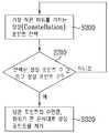
도 3은 본 발명에 따른 일 실시예로서, 옵티멀 성상의 포인트를 결정하는 순서를 나타낸 순서도3 is a flowchart illustrating a procedure of determining points of an optical constellation according to an embodiment of the present invention.
도 4는 본 발명에 따른 일 실시예로서, 16포인트를 갖는 옵티멀 성상을 개략적으로 나타낸 도면4 is a view schematically showing an optical constellation having 16 points as an embodiment according to the present invention.
도 5는 본 발명에 따른 일 실시예로서, 64포인트를 갖는 옵티멀 성상을 개략적으로 나타낸 도면5 is a diagram schematically showing an optical constellation having 64 points as an embodiment according to the present invention.
도 6은 본 발명에 따른 일 실시예로서, 256포인트를 갖는 옵티멀 성상을 개략적으로 나타낸 도면6 is a diagram schematically showing an optical constellation having 256 points as an embodiment according to the present invention.
도 7은 본 발명에 따른 일 실시예로서, 256포인트를 갖는 다른 옵티멀 성상을 개략적으로 나타낸 도면7 is a diagram schematically showing another optical constellation having 256 points as an embodiment according to the present invention.
도 8은 본 발명에 따른 일 실시예로서, 신호 수신 장치를 개략적으로 나타낸 블록도8 is a block diagram schematically illustrating an apparatus for receiving a signal according to an embodiment of the present invention.
도 9는 64포인트를 갖는 옵티멀 성상의 결정 경계(decision boundary)를 개략적으로 나타낸 블록도9 is a block diagram schematically showing a decision boundary of an optical constellation having 64 points;
도 10a는 본 발명에 따른 일 실시예로서, 수신된 옵티멀 성상 심볼을 디맵핑하는 심볼 디맵퍼를 개략적으로 나타낸 도면10A is a diagram schematically illustrating a symbol demapper for demapping a received optical constellation symbol according to an embodiment of the present invention.
도 10b는 본 발명에 따른 일 실시예로서, 수신된 옵티멀 성상 심볼을 디맵핑하는 다른 심볼 디맵퍼를 개략적으로 나타낸 도면FIG. 10B is a diagram schematically illustrating another symbol demapper for demapping a received optical constellation symbol according to an embodiment of the present invention. FIG.
도 11은 본 발명에 따른 일 실시예로서, 수신된 옵티멀 성상 심볼을 디맵핑하는 과정을 개략적으로 나타낸 도면11 is a diagram schematically illustrating a process of demapping a received optical constellation symbol according to an embodiment of the present invention.
도 12는 본 발명에 따른 일 실시예로서, 경계(edge) 영역의 수신된 옵티멀 성상 심볼을 디맵핑하는 과정을 개략적으로 나타낸 도면12 is a diagram schematically illustrating a process of demapping a received optical constellation symbol in an edge region according to an embodiment of the present invention.
도 13은 본 발명에 따른 일 실시예로서, 또 다른 신호 송신 장치를 개략적으로 나타낸 블록도13 is a block diagram schematically showing another signal transmission apparatus according to an embodiment of the present invention.
도 14는 본 발명에 따른 일 실시예로서, 순방향 오류정정부를 개략적으로 나타낸 블록도14 is a block diagram schematically showing a forward error correction as an embodiment according to the present invention.
도 15는 본 발명에 따른 일 실시예로서, 입력 데이터를 인터리빙시키는 인터리버를 나타낸 도면15 illustrates an interleaver for interleaving input data according to an embodiment of the present invention.
도 16은 본 발명에 따른 일 실시예로서, 선형 프리코딩부를 개략적으로 나타낸 블록도16 is a block diagram schematically showing a linear precoding unit according to an embodiment of the present invention.
도 17(a) 내지 17(c)는 본 발명에 따른 일 실시예로서, 입력 데이터를 분산시키는 코드의 매트릭스를 나타낸 도면17A to 17C illustrate a matrix of codes for distributing input data according to an embodiment of the present invention.
도 18은 본 발명에 따른 일 실시예로서, 전송 프레임의 구조를 나타낸 도면18 is a diagram illustrating a structure of a transmission frame according to an embodiment of the present invention.
도 19는 본 발명에 따른 일 실시예로서, 신호 송신 장치에서 복수의 전송 경로를 갖는 경우를 개략적으로 나타낸 블록도19 is a block diagram schematically illustrating a case in which a signal transmission apparatus has a plurality of transmission paths according to an embodiment of the present invention.
도 20(a) 내지 20(e)는 본 발명에 따른 일 실시예로서, 입력 심볼을 분산시키는 2×2 코드 매트릭스의 일 예를 나타낸 도면20 (a) to 20 (e) illustrate an example of a 2x2 code matrix for distributing input symbols according to an embodiment of the present invention.
도 21은 본 발명에 따른 일 실시예로서, 인터리버의 일 예를 나타낸 도면21 is a diagram illustrating an example of an interleaver according to an embodiment of the present invention.
도 22는 본 발명에 따른 일 실시예로서, 도 21의 인터리버의 구체적인 예를 나타낸 도면FIG. 22 is a diagram illustrating a specific example of the interleaver of FIG. 21 according to an embodiment of the present invention. FIG.
도 23은 본 발명에 따른 일 실시예로서, 다중 입출력 인코딩 방식의 일 예를 나타낸 도면23 is a diagram illustrating an example of a multiple input / output encoding scheme according to an embodiment of the present invention.
도 24(a)는 본 발명에 따른 일 실시예로서, 파일럿 심볼구간의 구조를 나타낸 도면24 (a) is a diagram illustrating the structure of a pilot symbol interval according to an embodiment of the present invention.
도 24(b)는 본 발명에 따른 일 실시예로서, 파일럿 심볼구간의 다른 구조를 나타낸 도면24B is a diagram illustrating another structure of a pilot symbol period according to an embodiment of the present invention.
도 25는 본 발명에 따른 일 실시예로서, 또 다른 신호 수신 장치를 개략적으로 나타낸 블록도25 is a block diagram schematically illustrating another signal receiving apparatus according to an embodiment of the present invention.
도 26(a)는 본 발명에 따른 일 실시예로서, 선형 프리코딩 디코더의 예를 개략적으로 나타낸 블록도26 (a) is a block diagram schematically showing an example of a linear precoding decoder as an embodiment according to the present invention.
도 26(b)는 본 발명에 따른 일 실시예로서, 선형 프리코딩 디코더의 또 다른 일 예를 개략적으로 나타낸 블록도FIG. 26 (b) is a block diagram schematically illustrating another example of a linear precoding decoder according to an embodiment of the present invention. FIG.
도 27(a) 내지 27(c)는 본 발명에 따른 일 실시예로서, 분산된 심볼을 복원시키는 2×2 코드 매트릭스의 일 예를 나타낸 도면27 (a) to 27 (c) illustrate an example of a 2x2 code matrix for reconstructing distributed symbols as an embodiment according to the present invention.
도 28은 본 발명에 따른 일 실시예로서, 순방향 오류정정 복호부를 개략적으로 나타낸 블록도28 is a block diagram schematically showing a forward error correction decoding unit according to an embodiment of the present invention.
도 29는 본 발명에 따른 일 실시예로서, 신호 수신 장치에서 복수의 수신 경로를 갖는 경우를 개략적으로 나타낸 블록도29 is a block diagram schematically illustrating a case in which a signal receiving apparatus has a plurality of receiving paths according to an embodiment of the present invention.
도 30은 본 발명에 따른 일 실시예로서, 다중 입출력 디코딩 방식의 일 예를 나타낸 도면30 illustrates an example of a multiple input / output decoding scheme according to an embodiment of the present invention.
도 31은 본 발명에 따른 일 실시예로서, 도 30의 구체적인 예를 나타낸 도면31 is a view showing a specific example of FIG. 30 as an embodiment according to the present invention.
도 32는 본 발명에 따른 일 실시예로서, 신호 송신 방법의 순서를 나타낸 순서도32 is a flowchart illustrating a signal transmission method according to an embodiment of the present invention.
도 33은 본 발명에 따른 일 실시예로서, 신호 수신 방법의 순서를 나타낸 순서도33 is a flowchart illustrating a signal receiving method according to an embodiment of the present invention.
*도면의 주요 부분에 대한 부호의 설명* Explanation of symbols for the main parts of the drawings
100 : 아웃터 인코더 110 : 인너 인코더100: outer encoder 110: inner encoder
120 : 제1인터리버 130 : 심볼 맵퍼120: first interleaver 130: symbol mapper
140 : 선형 프리코딩부 150 : 제2인터리버140: linear precoding unit 150: second interleaver
160 : 프레임 형성부 170 : 변조부160: frame forming unit 170: modulator
180 : 전송부180: transmission unit
본 발명은 신호 송수신 방법 및 신호 송수신 장치에 관한 것으로서, 더욱 자세하게는 데이터 전송률을 높일 수 있는 신호 송수신 방법 및 송수신 장치에 관한 것이다.The present invention relates to a signal transmission and reception method and a signal transmission and reception apparatus, and more particularly, to a signal transmission and reception method and transmission and reception apparatus that can increase the data transmission rate.
사용자는 디지털 방송(Digital Broadcasting) 기술의 발전으로 인해 HD(High Definition)급의 동영상과 디지털 음향 등의 뛰어남을 경험하게 되었고, 압축 알고리즘의 계속적인 발전과 하드웨어의 고성능화에 의해 앞으로 더 나은 환경을 접하게 될 것이다. 디지털 텔레비전(DTV)은 상기 디지털 방송신호를 수신하여 영상, 음성과 더불어 다양한 부가 서비스를 사용자에게 제공할 수 있다.Users have experienced superiority of HD (High Definition) video and digital sound due to the development of Digital Broadcasting technology, and the better environment is being developed through the continuous development of compression algorithms and high performance of hardware. Will be. The digital television (DTV) may receive the digital broadcast signal and provide various additional services in addition to video and audio to the user.
상기 디지털 방송의 보급과 더불어 더 나은 영상, 음향 등과 같은 서비스에 대한 요구가 증가하고 있고, 사용자가 원하는 데이터의 크기나 방송 채널의 수가 점차 커지고 있다.With the spread of digital broadcasting, demands for better services such as video and audio are increasing, and the size of data desired by the user and the number of broadcasting channels are gradually increasing.
그러나, 기존의 신호 송수신 방식으로는 증가하는 데이터의 크기나 방송 채널의 수를 감당하기 어렵게 되었다. 따라서, 기존의 신호 송수신 방식보다 채널의 대역폭 효율이 높고, 신호 송수신 네트워크 망을 구성하는 비용이 적게 요구되는 새로운 신호 송수신 기술에 대한 요구가 늘어나고 있다.However, it is difficult to cope with the increased data size and the number of broadcast channels using the conventional signal transmission and reception method. Accordingly, there is an increasing demand for a new signal transmission / reception technique requiring higher bandwidth efficiency of a channel than a conventional signal transmission / reception scheme and requiring a low cost of configuring a signal transmission / reception network.
본 발명은 상기와 같은 문제점을 해결하기 위한 것으로서, 기존의 신호 송수신 네트워크 망을 이용할 수 있고, 데이터의 전송률을 높일 수 있는 신호 송수신 방법 및 송수신 장치를 제공하는 데 목적이 있다.The present invention has been made to solve the above problems, and an object of the present invention is to provide a signal transmitting / receiving method and a transmitting / receiving apparatus capable of using an existing signal transmitting / receiving network network and increasing a data transmission rate.
상기와 같은 문제점을 해결하기 위한 본 발명에 따른 신호 송신 장치는, 입력된 데이터에 대해 오류를 검출하고 수정할 수 있도록 부호화하는 순방향 오류정정부, 상기 오류정정 인코딩된 데이터를 인터리빙(interleaving)하는 제1인터리버, 상기 인터리빙된 데이터를 옵티멀 성상(optimal constellation) 매핑 방식에 따른 심볼 데이터로 매핑(mapping)하는 심볼 맵퍼, 및 상기 심볼 데이터를 주파수 영역에서 분산시키고, 상기 분산된 데이터를 인터리빙(interleaving)하여 출력하는 페이딩 코딩부를 포함한다.A signal transmission apparatus according to the present invention for solving the above problems, a forward error correction for encoding to detect and correct an error with respect to the input data, the first interleaving the error correction encoded data (interleaving) An interleaver, a symbol mapper for mapping the interleaved data to symbol data according to an optimal constellation mapping scheme, and distributing the symbol data in a frequency domain and interleaving the distributed data and outputting the interleaved data And a fading coding unit.
본 발명에 따른 신호 송신 방법은, 입력된 데이터에 대해 오류를 검출하고 수정할 수 있도록 부호화하는 순방향 오류정정 인코딩 단계, 상기 오류정정 인코딩된 데이터를 인터리빙하는 단계, 상기 인터리빙된 데이터를 옵티멀 성상(optimal constellation) 매핑 방식에 따른 심볼 데이터로 매핑하는 단계, 및In accordance with another aspect of the present invention, there is provided a signal transmission method comprising: forward error correction encoding for encoding and detecting an error on an input data, interleaving the error correction encoded data, and optimal constellation of the interleaved data. Mapping to symbol data according to a mapping method, and
상기 심볼 데이터를 주파수 영역에서 분산시키고, 상기 분산된 데이터를 인터리빙하여 출력하는 페이딩 코딩 단계를 포함한다.And a fading coding step of distributing the symbol data in the frequency domain and interleaving and outputting the distributed data.
본 발명에 따른 신호 수신 장치는, 수신된 심볼 데이터를 디인터리빙(de-interleaving)하고, 주파수 영역에 분산되어 있는 데이터를 복원하여 출력하는 페이딩 디코딩부, 상기 복원되어 출력된 심볼 데이터를 옵티멀 성상(optimal constellation) 방식에 따라 디매핑(demapping)하여 상기 심볼에 해당하는 비트 데이터를 출력하는 심볼 디맵퍼, 상기 디매핑된 비트 데이터를 디인터리빙하여 순서를 복원하는 제1디인터리버, 및 상기 디인터리빙된 데이터를 디코딩하여 오류를 검출하고 수정하는 순방향 오류정정 복호부를 포함한다.A signal receiving apparatus according to the present invention includes a fading decoding unit for de-interleaving received symbol data, restoring and outputting data distributed in a frequency domain, and performing an optical constellation of the restored output symbol data. The symbol demapper outputs bit data corresponding to the symbol by demapping according to an optimal constellation method, a first deinterleaver for deinterleaving the demapped bit data, and restoring the order, and the deinterleaved data. It includes a forward error correction decoder that detects and corrects errors by decoding the data.
본 발명에 따른 신호 수신 방법은, 수신된 심볼 데이터를 디인터리빙하고, 주파수 영역에 분산되어 있는 데이터를 복원하여 출력하는 단계, 상기 복원되어 출력된 심볼 데이터를 옵티멀 성상 방식에 따라 디매핑하여 상기 심볼에 해당하는 비트 데이터를 출력하는 단계, 상기 디매핑된 비트 데이터를 디인터리빙하여 순서를 복원하는 단계, 및 상기 디인터리빙된 데이터를 디코딩하여 오류를 검출하고 수정하는 단계를 포함한다.In the signal receiving method according to the present invention, deinterleaving the received symbol data, restoring and outputting data distributed in a frequency domain, and demapping the restored output symbol data according to an optical constellation method, the symbol Outputting the bit data corresponding to the data, deinterleaving the demapped bit data to restore an order, and decoding and decoding the deinterleaved data to detect and correct an error.
본 발명의 다른 목적, 특성 및 이점들은 첨부한 도면을 참조한 실시 예들의 상세한 설명을 통해 명백해질 것이다.Other objects, features and advantages of the present invention will become apparent from the following detailed description of embodiments taken in conjunction with the accompanying drawings.
아울러, 본 발명에서 사용되는 용어는 가능한 한 현재 널리 사용되는 일반적인 용어를 선택하였으나, 특정한 경우는 출원인이 임의로 선정한 용어도 있으며 이 경우 해당되는 발명의 설명 부분에서 상세히 그 의미를 기재하였으므로, 단순한 용어의 명칭이 아닌 용어가 가지는 의미로서 본 발명을 파악하여야 함을 밝혀 두고자 한다.In addition, the terms used in the present invention was selected as a general term widely used as possible now, but in certain cases, the term is arbitrarily selected by the applicant, in which case the meaning is described in detail in the corresponding description of the invention, It is to be clear that the present invention is to be understood as the meaning of terms rather than names.
이와 같이 구성된 본 발명에 따른 신호 송수신 방법 및 신호 송수신 장치의 동작을 첨부한 도면을 참조하여 상세히 설명하면 다음과 같다.Operation of the signal transmission and reception method and the signal transmission and reception device according to the present invention configured as described above will be described in detail with reference to the accompanying drawings.
도 1은 본 발명에 따른 일 실시예로서, 신호 송신 장치를 개략적으로 나타낸 블록도이다. 상기 도 1의 신호 송신 장치는 방송 신호 등 비디오 데이터를 전송하는 신호 송신 시스템이 될 수 있다. 예를 들어, DVB(digital video broadcasting) 시스템에 따른 신호 송신 시스템일 수 있다. 도 1을 참조하여 본 발명에 따른 신호 송신 시스템의 실시예를 설명하면 다음과 같다.1 is a block diagram schematically showing a signal transmission apparatus according to an embodiment according to the present invention. The signal transmission apparatus of FIG. 1 may be a signal transmission system for transmitting video data such as a broadcast signal. For example, it may be a signal transmission system according to a digital video broadcasting (DVB) system. An embodiment of a signal transmission system according to the present invention will be described with reference to FIG. 1.
도 1의 실시예는 아웃터 인코더(Outer encoder)(100), 인너 인코더(Inner encoder)(110), 제1인터리버(interleaver)(120), 심볼맵퍼(symbol mapper)(130), 선형 프리코딩부(140), 제2인터리버(150), 프레임 형성부(frame builder)(160), 변조부(modulator)(170) 및 전송부(180)를 포함한다.1 illustrates an
상기 아웃터 코더(100)와 인너 코더(110)는 각각 입력된 신호를 부호화하여 출력함으로써, 전송되는 데이터에 발생한 오류를 수신기에서 검출하고, 상기 오류를 수정할 수 있도록 한다. 즉, 상기 아웃터 코더(100)와 인너 코더(110)는 순방향 오류정정부(Forward Error Correcting : FEC)로 볼 수 있다.The
상기 아웃터 코더(100)는 입력된 신호에 대한 송신 성능을 향상시키기 위해 입력 데이터를 부호화하고, 인너 코더(110)는 송신 신호에 에러 발생을 대비하여 송신할 신호를 다시 부호화한다. 상기 각 인코더의 종류는, 해당하는 신호 송신 시스템에서 사용하는 코딩 방식에 따라 다를 수 있다.The
제1인터리버(120)는 상기 인너 코더(110)에서 출력된 신호가 전송될 경우 겪을 수 있는 버스트 에러(burst error)에 강인하도록 데이터 열을 랜덤한 위치로 분산시키는 역할을 한다. 예를 들어, 상기 제1인터리버(120)에는 블록(block) 인터리빙 방식이나 컨벌루션(convolution) 인터리빙 방식 등이 사용될 수 있다. 상기 제1 인터리버(120)의 종류는 해당하는 신호 송신 시스템에서 사용하는 방식에 따라 다를 수 있다.The
심볼맵퍼(130)는 상기 제1인터리버(120)에서 인터리빙된 데이터를 전송 방식에 따른 심볼(symbol)로 매핑한다. 예를 들어, 상기 심볼 맵퍼(130)의 매핑 방식으로 QAM(Quadrature Amplitude Modulation), QPSK(Quadrature Phase Shift Keying), APSK(Amplitude Phase Shift Keying), PAM(Pulse Amplitude Modulation) 등이 사용될 수 있다. 본 발명에서는 상기 매핑 방식으로 옵티멀 성상(optimal constellation) 매핑 방식을 이용하는 것을 제안한다.The
도 2는 본 발명에 따른 일 실시예로서, 옵티멀 성상(optimal constellation) 포인트의 위치를 개략적으로 나타낸 도면이다. 옵티멀 성상 매핑을 위해 상기 포인트가 사용될 수 있다. 상기 성상 포인트의 숫자는 파워를 나타낸다.FIG. 2 is a diagram schematically showing a position of an optimal constellation point according to an embodiment of the present invention. The point can be used for optical constellation mapping. The number of constellation points represents power.
상기 옵티멀 성상 포인트들의 x축 값은 홀수(1, 3, 5, …) 또는 짝수(2, 4, 6, …)가 될 수 있으며, y축 값은
예를 들어, x축 위에 위치한 포인트의 경우 1, 3, 5, …의 홀수 값을 가지며, 파워는 각각 1, 9, 25, … 이다. y축 위에 위치한 포인트의 경우


상기와 같이 포인트를 원형에 가깝게 위치시키고, 가능한 포인트의 위치를 DC위치에서 멀리함으로써, 전송 파워를 효율적으로 사용할 수 있다.As described above, by placing the point as close to the circle as possible and as far as possible from the DC position, the transmission power can be used efficiently.
상기 도 2와 같은 포인트들의 위치 이외에, 상기 포인트들을 x축, y축, 또는 원점에 대하여 대칭 시켜 얻어진 위치를 사용할 수도 있다. 또는, 상기 포인트들의 위치를 원점을 축으로 임의의 각도로 회전시켜 얻어진 위치를 사용할 수도 있다. 이는 구현 예에 따라 달라질 수 있다.In addition to the positions of the points shown in FIG. 2, a position obtained by symmetrical with respect to the x-axis, the y-axis, or the origin may be used. Alternatively, the positions obtained by rotating the positions of the points at arbitrary angles about the origin may be used. This may vary depending on implementation.
도 3은 본 발명에 따른 일 실시예로서, 옵티멀 성상의 포인트를 결정하는 순서를 나타낸 순서도이다. 상기 도 2와 같은 성상 포인트 가운데 필요한 수의 옵티멀 성상 포인트를 얻는다.3 is a flowchart illustrating a procedure of determining an optical constellation point according to an embodiment of the present invention. The required number of optical constellation points are obtained among the constellation points as shown in FIG. 2.
먼저, 상기 도 2와 같은 성상 포인트 가운데 가장 작은 파워를 가지는 성상 포인트를 선택한다(S300). 그리고 상기 선택된 성상 포인트의 수와 필요한 성상 포인트의 수를 비교한다(S310). 만약, 상기 선택된 성상 포인트의 수가 더 적으면, 다시 S300 단계를 수행하여 선택되지 않은 포인트 가운데 가장 작은 파워를 가지는 성상 포인트를 선택한다. 만약 상기 선택된 성상 포인트의 수가 더 크면, 넘은 포인트의 수만큼 파워가 큰 순서대로 성상 포인트를 제거한다(S320). 상기와 같은 과정을 통해 원하는 수의 성상 포인트를 얻을 수 있으며, 상기 얻어진 성상 포인트를 이용하여 입력된 데이터를 심볼 데이터로 매핑할 수 있다.First, the constellation point having the smallest power among the constellation points as shown in FIG. 2 is selected (S300). In operation S310, the number of the selected constellation points and the number of necessary constellation points are compared. If the number of the selected constellation points is smaller, step S300 is performed again to select constellation points having the smallest power among the unselected points. If the selected number of constellation points is larger, the constellation points are removed in order of increasing power by the number of points exceeded (S320). Through the above process, a desired number of constellation points can be obtained, and the input data can be mapped to symbol data using the obtained constellation points.
도 4 내지 도 7은 본 발명에 따른 일 실시예로서, 상기와 같은 방식에 따라 선택된 포인트를 갖는 옵티멀 성상을 개략적으로 나타낸 도면이다. 즉, 도 4내지 도 7은 각각 16포인트, 64포인트, 256포인트, 256포인트를 갖는 옵티멀 성상을 개략적으로 나타낸 도면이다. 다만, 도 6의 경우에는 상기 도 2에서 설명한 성상 포인트 위치와 다른 위치를 가지는 다른 실시예의 경우로서, DC위치에 가까운 성상 포인트를 가지는 경우이다.4 to 7 are schematic diagrams showing an optical constellation having a point selected according to the above-described exemplary embodiment according to the present invention. That is, FIGS. 4 to 7 schematically show an optical constellation having 16 points, 64 points, 256 points, and 256 points, respectively. However, in FIG. 6, another embodiment having a position different from the constellation point position described with reference to FIG. 2 is a case where the constellation point is close to the DC position.
상기에서 설명한 바와 같이, 상기 도 4 내지 도 7의 포인트들의 위치 이외에, 상기 포인트들을 x축, y축, 또는 원점에 대하여 대칭 시켜 얻어진 위치를 사용할 수도 있다. 또는, 상기 포인트들의 위치를 원점을 축으로 임의의 각도로 회전시켜 얻어진 위치를 사용할 수도 있다. 이는 구현 예에 따라 달라질 수 있다.As described above, in addition to the positions of the points of FIGS. 4 to 7, a position obtained by symmetry of the points with respect to the x-axis, the y-axis, or the origin may be used. Alternatively, the positions obtained by rotating the positions of the points at arbitrary angles about the origin may be used. This may vary depending on implementation.
상기 심볼맵퍼(130)는 상기와 같이 정해진 포인트 수를 갖는 옵티멀 성상 매핑 방식에 따라, 입력된 데이터를 심볼 매핑하여 출력한다.The
선형 프리코딩부(140)는 입력된 심볼 데이터를 여러 개의 출력 심볼 데이터에 분산시켜, 주파수 선택적 페이딩(frequency selective fading) 채널을 겪었을 때 모든 정보가 페이딩으로 손실될 확률을 줄여준다.The
제2인터리버(150)는 상기 선형프리코딩부(140)에서 출력된 심볼 데이터를 다시 인터리빙하여, 상기 심볼 데이터가 동일한 주파수 선택적인 페이딩을 겪지 않도록 한다. 상기 제2인터리버(150)에는 블록 인터리빙 방식이나 컨벌루션 인터리빙 방식 등이 사용될 수 있다.The
프레임 형성부(160)는 상기 인터리빙된 신호를 직교 주파수 다중 분할(Orthogonal Frequency Division Multiplex : OFDM) 방식으로 변조할 수 있도록, 데이터 구간에 파일럿(pilot) 신호를 삽입하여 프레임을 형성한다.The
변조부(170)는 상기 프레임 형성부(160)에서 출력된 데이터들을 각각 OFDM의 부반송파(sub carrier)들에 실어 전송할 수 있도록 가드 구간(guard interval)을 삽입하여 변조한다. 전송부(180)는 변조부(170)에서 출력된 보호 구간과 데이터 구간을 가진 디지털 형식의 신호를 아날로그 신호로 변환하여 송신(transmit)한다.The
도 8은 본 발명에 따른 일 실시예로서, 신호 수신 장치를 개략적으로 나타낸 블록도이다. 상기 도 8의 실시예는 DVB 수신 장치 등에 포함될 수 있다.8 is a block diagram schematically illustrating an apparatus for receiving a signal according to an embodiment of the present invention. The embodiment of FIG. 8 may be included in a DVB receiver.
도 8의 본 발명에 따른 실시예는 수신부(800), 동기부(810), 복조부(820), 프레임 파싱(parsing)부(830), 제1디인터리버(deinterleaver)(840), 선형 프리코딩 디코더(850), 심볼디맵퍼(symbol demapper)(860), 제2디인터리버(870), 인너 디코더(inner decoder)(880) 및 아웃터 디코더(outer decoder)(890)를 포함한다.8, the
수신부(800)는 수신된 RF 신호의 주파수 대역을 다운 컨버전(down conversion)한 후 디지털 신호로 변환하여 출력한다. 동기부(810)는 수신부(800)에서 출력된 수신 신호의 주파수 영역과 시간 영역의 동기를 획득하여 출력한다. 상기 동기부(810)는 주파수 영역 신호의 동기 획득을 위해 복조부(820)가 출력하는 데이터의 주파수 영역의 오프셋(offset) 결과를 이용할 수 있다.The
복조부(820)는 상기 동기부(810)에서 출력된 수신 데이터를 복조하고, 가드구간(guard interval)을 제거한다. 이를 위해 복조부(820)는 수신 데이터를 주파수 영역으로 변환시키고, 서브 캐리어(sub carrier)에 분산된 데이터 값을 각각의 부반송파에 할당되었던 값으로 디코딩한다. 프레임 파싱부(830)는 상기 복조부(820) 에서 복조된 신호의 프레임 구조에 따라 파일럿 심볼을 제외하고 데이터 심볼 구간의 심볼 데이터를 출력할 수 있다.The
제1디인터리버(840)는 상기 프레임 파싱부(830)에서 출력된 데이터 열에 대해 디인터리빙(de-interleaving)을 수행하여 데이터를 인터리빙되기 전의 순서로 복원시킨다. 상기 제1디인터리버(840)는 상기 도 1의 제2인터리버(150)에서 인터리빙한 방식에 대응되는 방식에 따라 디인터리빙하여 데이터 열의 순서를 복원한다.The
선형 프리코딩 디코더(850)는 신호 송신 장치에서 데이터를 분산한 과정의 역과정을 수행하여, 상기 선형 프리코딩 디코더(850)에 입력된 데이터에 분산되어 있는 본래의 데이터를 복원한다.The
심볼디맵퍼(860)는 상기 선형 프리코딩 디코더(850)에서 복원된 심볼 데이터를 비트열로 복원할 수 있다. 상기 심볼 디매핑 방식은 상기 도 1과 같은 송신 장치의 심볼맵퍼(130)에서 사용한 매핑 방식에 대응되는 방식을 사용한다. 이하 설명의 편의를 위해, 상기 도 1의 심볼맵퍼(130)에서 64포인트를 갖는 옵티멀 성상 매핑 방식에 따라 심볼 데이터를 매핑하였다고 가정한다. 상기 포인트의 수는 설명의 편의를 위해 정한 하나의 실시 예에 불과하다.The symbol demapper 860 may restore the symbol data restored by the
도 9는 64포인트를 갖는 옵티멀 성상의 결정 경계(decision boundary)를 개략적으로 나타낸 블록도이다. 심볼디맵퍼(860)는 상기 도 9와 같은 결정 경계를 이용하여, 수신된 심볼 데이터를 디맵핑한다. 옵티멀 성상 매핑 방식의 경우, 전송 파워를 효율적으로 사용하기 위해 벌집 구조의 성상을 가지며, 심볼디맵퍼(860)에서는 상기 도 9와 같이 심볼마다 육각형의 결정 경계를 갖는다. 다만, 가장 가장자 리에 위치한 포인트에 해당하는 심볼은 육각형이 아닌 한 쪽면이 터진 형태의 결정 경계를 갖는다.9 is a block diagram schematically illustrating a decision boundary of an optical constellation having 64 points. The symbol demapper 860 demaps the received symbol data using the decision boundary shown in FIG. 9. In the case of the optical constellation mapping scheme, the constellation has a honeycomb constellation in order to efficiently use transmission power, and the
입력된 심볼 데이터가 상기 도 9와 같은 결정 경계 가운데 특정 육각형 내에 위치한 것으로 인식되면, 심볼디맵퍼(860)는 상기 입력된 심볼 데이터를 상기 특정 육각형에 해당하는 포인트의 심볼로 디맵핑한다.If it is recognized that the input symbol data is located within a specific hexagon among the crystal boundaries of FIG. 9, the
도 10a는 본 발명에 따른 일 실시예로서, 수신된 옵티멀 성상 심볼을 디맵핑하는 심볼 디맵퍼를 개략적으로 나타낸 도면이고, 도 10b는 본 발명에 따른 일 실시예로서, 수신된 옵티멀 성상 심볼을 디맵핑하는 다른 심볼 디맵퍼를 개략적으로 나타낸 도면이다.10A is a diagram schematically illustrating a symbol demapper for demapping a received optical constellation symbol according to an embodiment of the present invention, and FIG. 10B is a diagram illustrating a received optical constellation symbol as an embodiment according to the present invention. FIG. Is a diagram schematically illustrating another symbol demapper to be mapped.
심볼디맵퍼(860)는 상기 도 9와 같은 옵티멀 성상의 결정 경계 전체를 한번에 이용하여 심볼 디맵핑을 할 수도 있고, 상기 도 10a, 10b의 심볼디맵퍼와 같이 직사각형 형태의 결정 경계를 사용하여 심볼 디맵핑을 할 수도 있다.The symbol demapper 860 may perform symbol demapping by using the entire crystal boundary of the optical property as shown in FIG. 9 at a time, or use a symbol boundary of a rectangular shape as in the symbol demapper of FIGS. 10A and 10B. You can also demap.
상기 도 10a의 심볼디맵퍼는 제1결정부(1000), 제2결정부(1002), 제1회전부(1004), 제3결정부(1006), 제4결정부(1008), 제2회전부(1010), 제5결정부(1012), 제6결정부(1014), 및 비트 변환부(1016)를 포함한다.The symbol demapper of FIG. 10A includes a
상기 심볼디맵퍼(860)에 심볼 데이터가 입력되면, 제1결정부(1000)는 육각형의 결정 경계 영역마다 마주보는 두 면을 이용한 직사각형 형태의 결정 경계 영역을 이용하여, 입력된 심볼 데이터가 상기 직사각형 형태의 결정 경계 영역에 위치하는지 결정한다. 제2결정부(1002)는 입력된 심볼 데이터가 성상 가장자리(constellation edge) 영역, 즉, 도 9와 같은 전체 결정 경계에서 도형을 이루지 않는 가장자리 영역에 위치하는 지에 대하여 결정을 내린다. 상기 제2결정부(1002)는 상기 가장자리 영역 가운데 실선으로 구분되는 결정 경계 영역에 위치하는지 결정한다. 상기 제1결정부(1000)와 제2결정부(1002)는 회전하지 않은 결정 경계를 이용하여, 입력된 심볼 데이터의 위치를 결정하는 결정부이다.When the symbol data is input to the
제1회전부(1004)는 상기 제1결정부(1000)와 제2결정부(1002)에서 사용된 결정 경계 전체를 60도 회전시키는 역할을 한다. 상기 제1회전부(1004)에서 출력된 데이터는 제3결정부(1006)에 입력된다. 상기 제3결정부(1006)는 상기 60도 회전된 전체 결정 경계 영역 가운데, 육각형의 결정 경계 영역마다 마주보는 두 면을 이용한 직사각형 형태의 결정 경계 영역을 이용하여, 입력된 심볼 데이터가 상기 직사각형 형태의 결정 경계 영역에 위치하는지 결정한다. 제4결정부(1008)는 입력된 심볼 데이터가 성상 가장자리 영역에 위치하는지에 대하여 결정을 내린다. 상기 제4결정부(1008)는 상기 가장자리 영역 가운데 1점 쇄선으로 구분되는 결정 경계 영역에 위치하는지 결정한다. 상기 제3결정부(1006)와 제4결정부(1008)는 1회 회전, 즉 60도 회전한 결정 경계를 이용하여, 입력된 심볼 데이터의 위치를 결정하는 결정부이다.The first
제2회전부(1010)는 상기 제3결정부(1006)와 제4결정부(1008)에서 사용된 결정 경계 전체를 다시 60도 회전시키는 역할을 한다. 상기 제2회전부(1010)에서 출력된 데이터는 제5결정부(1012)에 입력된다. 제5결정부(1012)는 상기 다시 60도가 회전된 전체 결정 경계 영역 가운데 육각형의 결정 경계 영역마다 마주보는 두 면을 이용한 직사각형 형태의 결정 경계를 이용하여, 입력된 심볼 데이터가 상기 직 사각형 형태의 결정 경계에 위치하는지 결정한다. 제6결정부(1014)는 입력된 심볼 데이터가 성상 가장자리 영역에 위치하는지에 대하여 결정을 내린다. 상기 제6결정부(1014)는 상기 가장자리 영역 가운데 점선으로 구분되는 결정 경계 영역에 위치하는지 결정한다. 상기 제5결정부(1012)와 제6결정부(1014)는 2회 회전, 즉 본래 결정 경계와 비교하여 120도 회전한 결정 경계를 이용하여, 입력된 심볼 데이터의 위치를 결정하는 결정부이다.The second
상기 제2결정부(1002), 제4결정부(1008), 제6결정부(1014)에서 성상 가장자리 영역에 대하여 결정하는 경우, x축, y축에 평행한 위치에 대한 결정은 새츄레이션(saturation) 기법을 사용하고, 사선 형태의 위치에 대한 결정은 상기 사선에 해당하는 직선 방정식을 이용하여 결정한다.In the case where the
비트 변환부(1016)는 상기 각 결정부에서 결정된 정보 즉, 입력된 심볼 데이터를 대응되는 포인트의 심볼로 결정한 값을 이용하여, 상기 결정된 심볼 값에 해당하는 비트 데이터로 변환한다.The
상기와 같이 2회의 회전과 6번의 결정 과정을 모두 수행할 수도 있고, 상기 6번의 결정 가운데 특정 결정에 의하여, 수신된 심볼 데이터에 대응되는 포인트의 심볼이 결정되면, 더 이상의 회전이나 결정은 하지 않고 바로 비트 변환부(1016)에 상기 결정 정보를 출력하여 비트 데이터로 변환할 수도 있다. 이는 구현 예에 따라 달라질 수 있다.As described above, both the two rotations and the six decision processes may be performed. If a symbol of a point corresponding to the received symbol data is determined by a specific decision among the six determinations, no further rotation or determination is performed. The decision information may be directly output to the
도 10b는 본 발명에 따른 일 실시예로서, 수신된 옵티멀 성상 심볼을 디맵핑하는 다른 심볼 디맵퍼를 개략적으로 나타낸 도면이다. 상기 도 10b의 심볼 디맵퍼 는 피드백(feed-back)을 이용한 반복(recursive) 디코딩 방식의 실시예이다.FIG. 10B is a diagram schematically illustrating another symbol demapper for demapping a received optical constellation symbol according to an embodiment of the present invention. The symbol demapper of FIG. 10B is an embodiment of a recursive decoding method using feedback.
상기 도 10b의 심볼 디맵퍼는 버퍼(1020), 선택부(1022), 제1결정부(1024), 제2결정부(1026), 회전부(1028), 및 비트 변환부(1030)를 포함한다.The symbol demapper of FIG. 10B includes a
버퍼(1020)는 입력된 심볼 데이터를 임시 저장하였다 출력한다. 선택부(1022)는 상기 버퍼(1020)에서 출력된 심볼 데이터와 회전부(1028)에서 출력된 심볼 데이터를 입력받아, 하나의 심볼 데이터를 출력한다. 상기 선택부(1022)는 반복 디코딩을 수행하는 경우 상기 회전부(1028)에서 피드백된 심볼 데이터를 출력하며, 새로운 심볼 데이터에 대하여 결정 과정을 수행하는 경우 상기 버퍼(1020)로부터 입력된 심볼 데이터를 출력한다.The
제1결정부(1024)는 육각형의 결정 경계 영역마다 마주보는 두 면을 이용한 직사각형 형태의 결정 경계 영역을 이용하여, 입력된 심볼 데이터가 상기 직사각형 형태의 결정 경계 영역에 위치하는지 결정한다. 그리고 제2결정부(1026)는 입력된 심볼 데이터가 성상 가장자리(constellation edge) 영역, 즉, 도 9와 같은 전체 결정 경계에서 도형을 이루지 않는 가장자리 영역에 위치하는 지에 대하여 결정을 내린다. 상기 제2결정부(1026)는 회전된 횟수에 따라, 각각 실선(0회 회전), 1점 쇄선(1회 회전), 점선(2회 회전)으로 구분되는 결정 경계 영역에 위치하는지 결정한다. 회전부(1028)는 상기 제1결정부(1024)와 제2결정부(1026)에서 사용된 결정 경계 전체를 60도 회전시키는 역할을 한다.The
비트 변환부(1030)는 상기 각 결정부에서 결정된 정보 즉, 입력된 심볼 데이터를 대응되는 포인트의 심볼로 결정한 값을 이용하여, 상기 결정된 심볼 값에 해 당하는 비트 데이터로 변환한다.The
상기 10b의 심볼 디맵퍼는 2회의 회전과 6번의 결정 과정을 모두 수행할 수도 있고, 반복 디코딩 과정 중에 상기 제1결정부(1024)와 제2결정부(1026)에서, 입력된 심볼 데이터에 대응되는 포인트의 심볼을 결정하면 바로 비트 변환부(1030)에 상기 결정 정보를 출력하여 비트 데이터로 변환할 수도 있다. 이는 구현 예에 따라 달라질 수 있다.The symbol demapper of 10b may perform both two rotations and six decision processes. The symbol demapper of 10b corresponds to the input symbol data in the
도 11은 본 발명에 따른 일 실시예로서, 수신된 옵티멀 성상 심볼을 디맵핑하는 과정을 개략적으로 나타낸 도면이고, 도 12는 본 발명에 따른 일 실시예로서, 가장자리(edge) 영역의 수신된 옵티멀 성상 심볼을 디맵핑하는 과정을 개략적으로 나타낸 도면이다.FIG. 11 is a diagram schematically illustrating a process of demapping a received optical constellation symbol according to an embodiment of the present invention, and FIG. 12 is a diagram illustrating received optical of an edge region as an embodiment according to the present invention. A diagram schematically illustrating a process of demapping constellation symbols.
상기 도 11은 전체 결정 경계 가운데 4개의 육각형 형태의 결정 경계 영역을 나타낸 도면이다. 상기 도면은 상기 도 10a 또는 도 10b의 결정부 가운데, 육각형의 결정 경계 영역에서 마주보는 두 면을 이용한 직사각형 형태의 결정 경계 영역을 이용하여, 심볼 데이터가 상기 직사각형 형태의 결정 경계 영역에 위치하는지 결정하는 결정부의 결정 과정을 나타낸다.FIG. 11 is a view showing four hexagonal crystal boundary regions among the entire crystal boundaries. The figure determines whether symbol data is located in the rectangular crystal boundary region by using a rectangular crystal boundary region using two surfaces facing each other in the hexagonal crystal boundary region among the crystal portions of FIG. 10A or 10B. The decision process of the decision part is shown.
우선, 회전하지 않은 첫 번째 결정 경계 형태에서, 육각형의 결정 경계 영역마다 좌우의 마주보는 두 면을 이용한 직사각형 형태의 결정 경계 영역을 이용하여, 입력된 심볼 데이터가 상기 직사각형 형태의 결정 경계 영역에 위치하는지 결정한다. 상기 결정이 끝나면 상기 결정 경계 전체를 60도 회전시켜, 다시 육각형의 결정 경계 영역마다 좌우의 마주보는 두 면을 이용한 직사각형 형태의 결정 경계 영역을 이용하여, 입력된 심볼 데이터가 상기 직사각형 형태의 결정 경계 영역에 포함되는지 결정한다. 그리고 결정 경계 전체를 다시 60도 회전시켜, 육각형의 결정 경계 영역마다 좌우의 마주보는 두 면을 이용한 직사각형 형태의 결정 경계를 이용하여, 입력된 심볼 데이터가 상기 직사각형 형태의 결정 경계 영역에 포함되는지 결정한다. 상기 도 11에서 두 번째 결정 경계 형태와 세 번째 결정 경계 형태는 상기 회전을 거치면서 결정과정을 거치는 영역을 중첩적으로 표현하였다.First, in the first non-rotating crystal boundary form, the input symbol data is positioned in the rectangular crystal boundary region using a rectangular crystal boundary region using two opposite sides of the hexagonal crystal boundary region. Determine. After the determination is completed, the entire crystal boundary is rotated by 60 degrees, and the input symbol data is converted into the rectangular crystal boundary by using a rectangular crystal boundary region using two opposite sides of each hexagonal crystal boundary region. Determine if it is included in the zone. Then, the entire crystal boundary is rotated by 60 degrees again to determine whether the input symbol data is included in the rectangular crystal boundary region by using the rectangular crystal boundary using two opposite sides of the hexagonal crystal boundary region. do. In FIG. 11, the second crystal boundary shape and the third crystal boundary shape superimpose the regions undergoing the crystallization process while rotating.
상기와 같이 2회 회전을 통해, 상기 직사각형 형태의 결정 경계 영역은 육각형 내부의 모든 영역을 커버할 수 있다. 따라서, 상기 육각형의 결정 경계 영역 각각에 대해, 상기 육각형의 결정 경계 영역을 갖는 포인트에 대응되는 심볼로 디맵핑할 수 있다.Through two rotations as described above, the rectangular crystal boundary region may cover all regions inside the hexagon. Therefore, for each of the hexagonal crystal boundary regions, it is possible to demap to a symbol corresponding to a point having the hexagonal crystal boundary region.
구현 예에 따라, 입력된 심볼 데이터가 상기 직사각형 형태의 결정 경계 영역에 위치한 것으로 인식되면, 남은 회전과 결정을 수행하지 않고 결정 과정을 마무리할 수도 있다. 그리고, 상기 설명에서는 육각형의 좌우 마주보는 두 면을 이용한 직사각형 형태의 결정 경계 영역을 이용하였으나, 좌우 면 이외, 다른 마주보는 두 면을 이용한 영역, 예를 들어, 비스듬히 기울어진 직사각형 형태의 결정 경계 영역을 이용할 수도 있다.According to an embodiment, if it is recognized that the input symbol data is located in the crystal boundary region of the rectangular shape, the determination process may be completed without performing the remaining rotation and determination. In the above description, although a rectangular crystal boundary region using two opposite sides of a hexagon is used, an area using two opposite sides other than the left and right sides, for example, an obliquely inclined rectangular boundary region, is used. Can also be used.
상기 도 12는 64포인트 옵티멀 성상 매핑 방식의 전체 결정 경계를 나타낸 도면이다. 상기 도 12는 상기 도 10a, 10b의 결정부 가운데 입력된 심볼 데이터가 성상 가장자리(constellation edge) 영역, 즉, 도형을 이루지 않는 가장자리 영역에 위치하는 지에 대하여 결정을 내리는 결정부의 결정 과정을 나타낸다.12 is a diagram illustrating an entire decision boundary of the 64-point optical constellation mapping scheme. FIG. 12 illustrates a determination process of a decision unit for making a determination as to whether the symbol data input among the determination units of FIGS. 10A and 10B is located in a constellation edge region, that is, an edge region that does not form a figure.
우선, 회전하지 않은 첫 번째 결정 경계 형태에서, 입력된 심볼 데이터가 성상 경계 영역 가운데, 실선으로 구분되는 영역에 위치하는지 결정한다. 상기 결정이 끝나면 상기 결정 경계 전체를 60도 회전시켜, 성상 경계 영역 가운데, 1점 쇄선으로 구분되는 영역에 위치하는지 결정한다. 그리고 결정 경계 전체를 다시 60도 회전시켜, 점선으로 구분되는 영역에 위치하는지 결정한다.First, in the first non-rotating decision boundary form, it is determined whether the input symbol data is located in a region separated by a solid line among the constellation boundary regions. After the determination is completed, the entire crystal boundary is rotated by 60 degrees to determine whether it is located in a region separated by a dashed line among constellation boundary regions. Then, the entire crystal boundary is rotated 60 degrees again to determine whether it is located in the area divided by a dotted line.
구현 예에 따라, 상기 실선으로 구분되는 영역, 1점 쇄선으로 구분되는 영역, 점선으로 구분되는 영역의 순서가 바뀔 수도 있다. 예를 들어, 도 12의 첫 번째 결정 경계 형태에서 점선으로 구분되는 영역의 결정 후에, 회전에 따라 각각 실선(1회 회전), 1점 쇄선(2회 회전)으로 구분되는 영역의 결정을 할 수도 있다.According to an embodiment, the order of the area divided by the solid line, the area divided by the dashed-dotted line, and the area divided by the dotted line may be changed. For example, after the determination of the area divided by the dotted line in the first crystal boundary form of FIG. have.
제2디인터리버(870)는 상기 심볼 디맵퍼(860)에서 디맵팽된 비트 데이터 열에 대해 인터리빙의 역과정을 수행한다. 상기 제2디인터리버(870)는 도 1의 제1인터리버(120)에 대응되는 디인터리빙을 수행한다. 인너 디코더(inner decoder)(880)는 상기 디인터리빙된 데이터를 복호하여 데이터에 포함된 에러를 정정할 수 있다. 그리고, 아웃터 디코더(outer decoder)(890)는 상기 인너 디코더(880)에서 디코딩된 비트 데이터에 대해 다시 에러 정정 복호 과정을 수행하여 출력한다. 상기 인너 디코더(880)과 아웃터 디코더(890)는 각각 도 1의 인너 인코더(110), 아웃터 디코더(100)에 대응되는 디코딩 방식에 따라 데이터를 디코딩한다.The
도 13은 본 발명에 따른 일 실시예로서, 또 다른 신호 송신 장치를 개략적으로 나타낸 블록도이다. 상기 송수신 시스템은 다중 입출력을 위한 MIMO(Multi Input Multi Output)를 사용할 수 있다. 상기 도 13의 송신 장치는 상기 도 1과 같 은 송신 장치에 다중 입출력 방식이 적용된 경우이다. 이하 도 13을 참조하여 본 발명에 따른 신호 송신 시스템의 실시예를 설명하면 다음과 같다.13 is a block diagram schematically showing another signal transmission apparatus according to an embodiment of the present invention. The transmission and reception system may use MIMO (Multi Input Multi Output) for multiple input and output. The transmitting apparatus of FIG. 13 is a case where a multiple input / output method is applied to the transmitting apparatus of FIG. Hereinafter, an embodiment of a signal transmission system according to the present invention will be described with reference to FIG. 13.
도 13의 실시예는 순방향 오류정정부(FEC(Forward Error Correction) encoder)(1300), 제1인터리버(interleaver)(1310), 심볼맵퍼(symbol mapper)(1320), 선형 프리코딩부(1330), 제2인터리버(1340), 다중 입출력 인코더(1350), 프레임 형성부(frame builder)(1360), 변조부(1370) 및 전송부(1380)를 포함한다. 상기 도 13의 실시예는 상기 신호 전송 시스템에서 신호가 처리되는 과정을 중심으로 설명한 것이다.13 illustrates a forward error correction (FEC)
순방향 오류정정부(1300)는 입력된 신호를 부호화하여 출력함으로써, 전송되는 데이터에 발생한 오류를 수신기에서 검출하고, 상기 오류를 수정할 수 있도록 한다. 상기 순방향 오류정정부(1300)는 상기 도 1의 아웃터 인코더(100)와 인너 인코더(110)에 대응된다.The forward
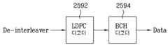
도 14는 본 발명에 따른 일 실시예로서, 순방향 오류정정부를 개략적으로 나타낸 블록도이다. 상기 도 14의 순방향 오류정정부는 도 13과 같은 송신 시스템에 사용될 수 있다. 상기 순방향 오류정정부는 아웃터 인코더(outer encoder)와 인너 인코더(inner encoder)로서 BCH(Bose-Chaudhuri-Hocquenghem) 인코더(1302)와 LDPC(Low Density Parity Check) 인코더(1304)를 포함한다.14 is a block diagram schematically showing a forward error correction as an embodiment according to the present invention. The forward error correction of FIG. 14 may be used in the transmission system of FIG. The forward error correcting unit includes a BCH (Bose-Chaudhuri-Hocquenghem)
LDPC 코드는 오류정정부호의 일종으로 데이터의 정보유실 확률을 가능한 한 적게 할 수 있다. 상기 LDPC 인코더(1304)는 블록의 길이를 크게 하여 전송 데이터가 전송 에러에 강인한 특성을 가지도록 할 수 있다. 또한, 블록 사이즈의 증가로 인한 하드웨어 복잡도 증가를 막기 위해서, 패리티 비트(parity bit)의 밀도를 작게 하여 복호화기의 복잡도를 감소시켜 줄 수 있다.The LDPC code is a type of error correcting code that can reduce the probability of data loss as much as possible. The
수신측의 출력 데이터에 에러 플로어(error floor)가 발생하는 것을 방지하기 위해, 추가적인 아웃터 인코더(outer encoder)로 BCH 인코더(1302)를 상기 LDPC 인코더(1304)에 연결(concatenate) 시킨다. 만약, 에러 플로어를 무시할 수 있을 정도의 LDPC 인코더(1304)가 사용된다면 상기 BCH 인코더(1302)는 사용되지 않을 수도 있다. 또는, 상기 BCH 인코더 이외의 다른 인코더를 아웃터 인코더로 사용할 수도 있다.In order to prevent an error floor from occurring in the output data of the receiver, a
상기 BCH 인코더(1302)와 LDPC 인코더(1304)를 거쳐 순방향 오류정정 인코딩된 데이터는 제1인터리버(1310)로 출력된다.Forward error correction encoded data is output to the
상기 제1인터리버(1310)는 전송 시 발생하는 버스트 에러(burst error)에 강인하도록, 상기 순방향 오류정정부(1300)에서 출력된 데이터 열을 섞어 랜덤한 위치로 분산시킨다. 상기 제1인터리버(1310)에는 컨벌루션 인터리버(convolution interleaver), 블록 인터리버(block interleaver) 등을 사용할 수 있으며, 이는 전송 시스템에 따라 달라질 수 있다.The
도 15는 본 발명에 따른 일 실시예로서, 입력 데이터를 인터리빙시키는 인터리버를 나타낸 도면이다. 상기 도 15의 인터리버는 블록 인터리버의 한 종류로 상기 제1인터리버(1310)에 사용될 수 있는 인터리버의 한 예이다.15 illustrates an interleaver for interleaving input data according to an embodiment of the present invention. The interleaver of FIG. 15 is an example of an interleaver that may be used for the
상기 도 15의 인터리버는 매트릭스(Matrix) 형태의 저장 공간(memory space)에 입력되는 데이터를 일정 패턴으로 저장하고, 상기 저장 패턴과 다른 패턴으로 데이터를 읽어 출력한다. 예를 들어, 도 15의 인터리버는 Nr의 행과 Nc의 열로 이루어진 저장공간(Nr×Nc)을 가지며, 상기 인터리버에 입력된 데이터는 상기 저장공간의 1열 1행 위치에서부터 채워진다. 1열의 1행에서부터 시작하여 1열의 Nr행까지 데이터를 저장하며, 상기 1열이 다 채워지면 그 다음 열(2열)의 1행에서부터 시작하여 Nr행까지 데이터를 저장한다. 상기와 같은 순서로 Nc열의 Nr행까지 데이터를 저장할 수 있다.The interleaver of FIG. 15 stores data input in a matrix-type storage space in a predetermined pattern and reads and outputs data in a pattern different from the storage pattern. For example, the interleaver of FIG. 15 has a storage space (Nr × Nc) consisting of a row of Nr and a column of Nc, and data input to the interleaver is filled from the position of one column, one row of the storage space. Data is stored starting from
그리고 상기 저장공간에 저장된 데이터를 읽는 경우에는, 저장공간의 1행 1열의 데이터에서부터 시작하여 1행 Nc열까지 해당 행의 데이터를 읽어서 출력한다. 그리고 해당 행의 데이터를 모두 읽으면, 다음 아래 행(2행)의 1열부터 시작하여 우측 방향으로 해당 행의 데이터를 읽어서 출력한다. 상기와 같은 순서로 Nr행의 Nc열까지 데이터를 읽어서 출력할 수 있다.이때, 데이터 블록의 MSB(Most Significant Bit) 위치는 좌측 최상단이며, LSB(Least Significant Bit) 위치는 우측 최하단이다.When reading the data stored in the storage space, the data of the row is read and output from the data of the first row to the first column of the storage space up to the first row Nc column. If all the data of the row is read, starting from the first column of the next lower row (row 2), the data of the row is read and output in the right direction. Data can be read and output up to Nc columns of Nr rows in the same order as described above. At this time, the MSB (Most Significant Bit) position of the data block is at the top left, and the LSB (Least Significant Bit) position is at the bottom right.
상기 인터리버의 저장 블록의 크기, 저장 패턴, 읽기 패턴 등은 하나의 실시 예이며 이는 구현 예에 따라 달라질 수 있다.A size, a storage pattern, a read pattern, and the like of the storage block of the interleaver are one embodiment, which may vary depending on the implementation.
상기 제1인터리버(1310)에서 인터리빙된 데이터는 심볼맵퍼(1320)에 입력된다. 심볼맵퍼(symbol mapper)(1320)는 상기에서 설명한 옵티멀 성상(optimal constellation) 방식의 매핑 방식을 사용할 수 있다.The interleaved data in the
선형 프리코딩부(1330)는 입력된 심볼 데이터를 여러 개의 출력 심볼 데이터에 분산시켜, 주파수 선택적 페이딩 채널을 겪었을 때 모든 정보가 페이딩으로 손 실될 확률을 줄여준다.The
도 16은 본 발명에 따른 일 실시예로서, 선형 프리코딩부를 개략적으로 나타낸 블록도이다. 상기 프리코딩부(1330)는 직/병렬 변환부(1332), 인코딩부(1334) 및 병/직렬 변환부(1336)를 포함한다.16 is a block diagram schematically showing a linear precoding unit as an embodiment according to the present invention. The
직/병렬 변환부(1332)는 입력된 데이터를 병렬(parallel) 데이터로 변환한다. 인코딩부(1334)는 상기 병렬 데이터를 인코딩 매트릭싱(matrixing)을 통해 여러 개의 데이터에 분산시킨다.The serial /
상기 인코딩 매트릭스는 출력 심볼과 입력 심볼을 비교해서, 상기 두 심볼이 틀릴 확률인 PEP(Pairwise Error Probability)가 최소화되도록 설계한다. PEP를 최소화하도록 설계하여 선형 프리코딩을 통해서 얻는 다이버시티 이득(diversity gain)과 코딩 이득(coding gain)을 최대로 할 수 있다.The encoding matrix is designed to compare an output symbol with an input symbol so that Pairwise Error Probability (PEP), which is a probability that the two symbols are wrong, is minimized. Designed to minimize PEP, the diversity gain and coding gain obtained through linear precoding can be maximized.
또한, 상기 인코딩 매트릭스를 통해 선형 프리코딩된 심볼의 최소 유클리드 거리(Euclidean distance)가 최대가 되도록 하면, 수신단에서 ML(Maximum Likelihood) 디코더를 사용할 경우 오류 확률(error probability)을 최소화시킬 수 있다.In addition, when the minimum Euclidean distance of a linear precoded symbol is maximized through the encoding matrix, an error probability may be minimized when the receiver uses a maximum likelihood (ML) decoder.
도 17(a)는 본 발명에 따른 일 실시예로서, 입력 데이터를 분산시키는 코드의 매트릭스를 나타낸 도면이다. 상기 도 17(a)는 상기 입력 데이터를 여러 개의 출력 데이터에 분산시키는 인코딩 매트릭스의 일 예로서 vanderMonde 매트릭스로 불린다. 입력 데이터들은 출력 데이터의 개수(L) 길이로 병렬 배열될 수 있다.17 (a) is a diagram illustrating a matrix of codes for distributing input data according to an embodiment of the present invention. 17 (a) is called a vanderMonde matrix as an example of an encoding matrix for distributing the input data into a plurality of output data. The input data may be arranged in parallel in the length (L) of the output data.
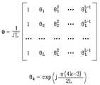
상기 매트릭스의 θ는 다음 수학식으로 표현될 수 있으며, 다른 방식으로도 정의가 가능하다. 상기 vanderMonde 매트릭스는 수학식 1으로 그 매트릭스 성분을 조절할 수 있다.Θ of the matrix may be expressed by the following equation, and may be defined in other ways. The vanderMonde matrix may adjust its matrix component by
상기 매트릭스는 각 입력 데이터를 대응되는 수학식 1의 위상만큼 회전시켜서 출력 데이터에 반영한다. 따라서, 상기 매트릭스의 특성에 따라 입력되는 값들을 적어도 둘 이상의 출력 값들로 분산시킬 수 있다.The matrix rotates each input data by the phase of the

수학식 1에서 L은 출력 데이터의 개수를 나타낸다. 도 16의 인코딩부(1334)로 입력되는 입력 데이터 군을 x라 하고, 상기 매트릭스에 의해 인코딩부(1334)에서 코딩되어 출력되는 데이터 군을 y라고 하면, y는 다음 수학식 2와 같다.In

도 17(b)는 본 발명에 따른 일 실시예로서, 입력 데이터를 분산시키는 다른 코드의 매트릭스를 나타낸 도면이다. 상기 도 17(b)는 상기 입력 데이터를 여러 개의 출력 데이터에 분산시키는 인코딩 매트릭스의 일 예로서 Hadamard 매트릭스로 불린다. 상기 도 17(b)의 매트릭스는 임의의 L=2k의 크기로 확장된 일반적인 형태이며, 'L'은 각 입력 심볼들을 분산시킬 출력 심볼들의 개수를 나타낸다.FIG. 17B is a diagram illustrating another code matrix for distributing input data according to an embodiment of the present invention. 17 (b) is called an Hadamard matrix as an example of an encoding matrix for distributing the input data into a plurality of output data. The matrix of FIG. 17 (b) is a general form extended to a size of any L = 2k , and 'L' represents the number of output symbols to distribute each input symbol.
상기 매트릭스의 출력 심볼은 L개의 입력 심볼의 합과 차로 얻을 수 있다. 다시 말하면, 각 입력 심볼은 L개의 출력 심볼에 분산시킬 수 있다.The output symbols of the matrix can be obtained by the sum and difference of the L input symbols. In other words, each input symbol can be spread over L output symbols.
상기 도 17(b)의 매트릭스의 경우에도, 도 16의 인코딩부(1334)로 입력되는 입력 데이터 군을 x라 하고, 상기 매트릭스에 의해 인코딩부(1334)에서 코딩되어 출력되는 데이터 군을 y라고 하면, y는 상기 매트릭스와 x의 곱이 된다.In the case of the matrix of FIG. 17B, the input data group input to the
도 17(c)는 본 발명에 따른 일 실시예로서, 입력 데이터를 분산시키는 다른 코드의 매트릭스를 나타낸 도면이다. 상기 도 17(c)는 상기 입력 데이터를 여러 개의 출력 데이터에 분산시키는 인코딩 매트릭스의 일 예로서 Golden code로 불린다. 상기 Golden code는 특별한 형태의 4x4 매트릭스이며, 서로 다른 두 개의 2x2 매트릭스가 교대로 사용되는 것으로 해석할 수 있다.17 (c) is a diagram illustrating another code matrix for distributing input data according to an embodiment of the present invention. 17 (c) is called golden code as an example of an encoding matrix for distributing the input data into a plurality of output data. The golden code is a special type of 4x4 matrix, and can be interpreted as two different 2x2 matrices alternately used.
상기 도 17(c)의 C는 골든 코드(golden code)의 코드 매트릭스(code matrix)를 나타내며, 상기 코드 매트릭스 내의 x1, x2, x3, x4는 상기 인코딩부(1334)에 입력되는 심볼 데이터를 나타낸다. 그리고 상기 코드 매트릭스 내의 각 상수들은 코드 매트릭스의 특성을 결정짓는다. 상기 코드 매트릭스의 각 상수들과 입력 심볼 데이터들로 계산된 행과 열의 값들은 출력 심볼 데이터를 나타낸다. 상기 심볼 데이터의 출력 순서는 구현 예에 따라 룰이 정의될 수 있다.C of FIG. 17C shows a code matrix of a golden code, and x1, x2, x3, and x4 in the code matrix represent symbol data input to the
병/직렬 변환부(1336)는 상기 인코딩부(1334)에서 수신된 데이터를 다시 직렬(serial) 데이터로 변환하여 출력한다.The parallel /
제2인터리버(1340)는 상기 선형 프리코딩부(1330)에서 출력된 심볼 데이터를 다시 인터리빙(interleaving)한다. 즉, 상기 제2인터리버(1340)에서 인터리빙을 수 행하여, 상기 선형 프리코딩부(1330)에서 출력된 데이터들에 분산되어 있는 심볼 데이터가 동일한 주파수 선택적 페이딩을 겪지 않도록 한다. 상기 제2인터리버(1340)에는 컨벌루션 인터리버(convolution interleaver), 블록 인터리버(block interleaver) 등을 사용할 수 있다.The
상기 선형 프리코딩부(1330)와 제2인터리버(1340)는 전송하고자 하는 데이터를 채널의 주파수 선택적 페이딩에 강인하도록 처리하는 부분으로, 주파수 선택적 페이딩 코딩부로 볼 수 있다.The
다중 입출력 인코더(1350)는 상기 제2인터리버(1340)에서 인터리빙된 데이터를 복수의 전송 안테나에 실리도록 인코딩한다. 다중 입출력 인코딩 방식에는 크게 공간 다중화(Spatial Multiplexing) 방식과 공간 다이버시티(Spatial Diversity) 방식이 있다. 공간 다중화는 송신기와 수신기에 다중의 안테나를 이용하여, 서로 다른 데이터를 동시에 전송함으로써 시스템의 대역폭을 더 증가시키지 않고, 보다 고속의 데이터를 전송할 수 있는 방식이다. 공간 다이버시티는 다중의 송신 안테나에서 같은 정보의 데이터를 전송하여 송신 다이버시티(diversity)를 얻는 방식이다.The multiple input /
이때, 공간 다이버시티(spatial diversity) 방식의 다중 입출력 인코더(150)로는 STBC(space-time block code)와 SFBC(space-frequency block code), STTC(space-time trellis code) 등이 사용될 수 있다. 공간 다중화(Spatial multiplex) 방식의 다중 입출력 인코더(1350)로는 단순히 데이터열을 송신 안테나 개수만큼 분리하여 전송하는 방식과 FDFR(full-diversity full-rate) code, LDC(linear dispersion code), V-BLAST(Vertical-Bell Lab. layered space-time)와 D-BLAST (diagonal-BLAST) 같은 방식이 사용될 수 있다.In this case, the spatial diversity multiple input /
프레임 형성부(1360)는 상기 프리코딩된 신호를 OFDM(Orthogonal Frequency Division Multiplex) 방식으로 변조할 수 있도록 파일럿(pilot) 신호를 삽입하여 프레임을 형성한다.The
도 18은 본 발명에 따른 일 실시예로서, 전송 프레임의 구조를 나타낸 도면이다. 상기 전송 프레임은 파일럿 캐리어(pilot carrier) 정보를 포함하는 파일럿 심볼 구간과 데이터 정보만을 포함하는 데이터 심볼 구간으로 구성된다.18 is a diagram illustrating a structure of a transmission frame according to an embodiment of the present invention. The transmission frame is composed of a pilot symbol period including pilot carrier information and a data symbol period including only data information.
상기 도 18에서 하나의 프레임은 M개의 구간을 포함하며, M-1개의 데이터 심볼 구간과 프리앰블(preamble)로 사용되는 한 개의 파일럿 심볼 구간으로 나뉜다. 그리고 상기와 같은 구조를 갖는 프레임이 반복된다.In FIG. 18, one frame includes M intervals, and is divided into M-1 data symbol intervals and one pilot symbol interval used as a preamble. The frame having the above structure is repeated.
각 심볼 구간에는 직교 주파수 다중 분할 (Orthogonal Frequency Division Multiplex : OFDM)방식의 각 서브 캐리어(sub carrier)의 수만큼 캐리어 정보가 포함된다. 파일럿 심볼 구간의 파일럿 캐리어 정보는 PAPR(Peak to Average Power Ratio)을 낮추기 위해 랜덤한 데이터로 구성된다. 그리고 상기 파일럿 캐리어 정보는 주파수 도메인(frequency domain)에서 자기상관값(auto-correlation)이 임펄스(impulse)인 형태를 갖는다.Each symbol period includes carrier information as many as the number of subcarriers of an Orthogonal Frequency Division Multiplex (OFDM) scheme. The pilot carrier information of the pilot symbol interval is composed of random data in order to lower the peak to average power ratio (PAPR). The pilot carrier information has a form in which auto-correlation is an impulse in the frequency domain.
데이터 심볼 구간에는 파일럿 캐리어 정보가 포함되지 않으며, 따라서 데이터 양(data capacity)을 늘릴 수 있다. DVB의 경우를 예를 들면, 파일럿 캐리어가 전체 유효 캐리어에서 차지하는 비율이 약 10%정도 되므로, 데이터 양(data capacity)의 증가율은 다음 수학식 3과 같다.Pilot carrier information is not included in the data symbol interval, and thus data capacity can be increased. For example, in the case of DVB, since the ratio of pilot carriers to total effective carriers is about 10%, the rate of increase of data capacity is expressed by the following equation.

상기 수학식 3에서 △는 증가율을 나타내며, M은 하나의 프레임에 포함된 구간의 수이다.In
변조부(1370)는 상기 프레임 형성부(1360)에서 출력된 데이터들을 각각 OFDM의 부반송파(sub carrier)들에 실어 전송할 수 있도록 가드 구간(guard interval)을 삽입하여 변조한다. 전송부(1380)는 변조부(1370)에서 출력된 보호 구간과 데이터 구간을 가진 디지털 형식의 신호를 아날로그 신호로 변환하여 송신(transmit)한다.The
도 19는 본 발명에 따른 일 실시예로서, 신호 송신 장치에서 복수의 전송 경로를 갖는 경우를 개략적으로 나타낸 블록도이다. 이하 설명의 편의를 위해 전송 경로가 2개인 경우를 예로 하여 설명한다.19 is a block diagram schematically illustrating a case in which a signal transmission apparatus has a plurality of transmission paths according to an embodiment of the present invention. For convenience of explanation, the following description will be given by using two transmission paths as an example.
도 19의 실시예는 순방향 오류정정부(1900), 제1인터리버(interleaver)(1910), 심볼맵퍼(symbol mapper)(1920), 선형 프리코딩부(1930), 제2인터리버(1940), 다중입출력 인코더(1950), 제1프레임 형성부(frame builder)(1960), 제2프레임 형성부(1965), 제1변조부(1970), 제2변조부(1975), 제1전송부(1980) 및 제2전송부(1985)를 포함한다.19 illustrates a
순방향 오류정정부(1900)에서 다중 입출력 인코더(1950)까지의 신호 처리 과 정은 상기 도 13에서 설명한 바와 동일하다.Signal processing from the forward
순방향 오류정정부(1900)는 BCH 인코더와 LDPC 인코더를 포함하며, 입력된 데이터를 오류정정 부호화하여 출력한다. 상기 출력된 데이터는 제1인터리버(1910)에서 인터리빙되어 데이터 열의 순서가 섞인다. 상기 제1인터리버(1910)에는 컨벌루션 인터리버, 블록 인터리버 등이 사용될 수 있다.The forward
심볼맵퍼(symbol mapper)(1920)는 상기에서 설명한 옵티멀 성상 방식의 매핑 방식에 따라, 입력받은 데이터를 심볼 데이터로 매핑한다.The
선형 프리코딩부(1930)는 직/병렬 변환부, 인코딩부 및 병/직렬 변환부를 포함한다.The
도 20(a) 내지 20(e)는 본 발명에 따른 일 실시예로서, 입력 심볼을 분산시키는 2×2 코드 매트릭스의 일 예를 나타낸 도면이다. 도 20(a) 내지 20(e)의 코드 매트릭스는 상기 도 19와 같은 송신 장치에 적용될 수 있으며, 상기 선형 프리코딩부(1930)의 인코딩부에 입력된 2개의 데이터를 2개의 출력 데이터에 분산시킨다.20A to 20E illustrate an example of a 2 × 2 code matrix for distributing input symbols according to an embodiment of the present invention. The code matrixes of FIGS. 20 (a) to 20 (e) may be applied to a transmitting apparatus as shown in FIG. 19, and two data inputted to an encoding unit of the
도 20(a)의 매트릭스는 상기 도 17(a)에서 설명한 vanderMonde 매트릭스의 실시예이다.The matrix of FIG. 20A is an embodiment of the vanderMonde matrix described with reference to FIG. 17A.
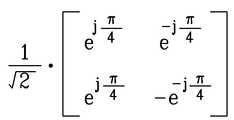
상기 도 20(a)의 매트릭스는 두 입력 데이터 가운데 첫번째 입력 데이터와 위상이 45도(


도 20(b)의 매트릭스는 상기 도 17(b)에서 설명한 Hadamard 매트릭스의 실시예이다.The matrix of FIG. 20 (b) is an embodiment of the Hadamard matrix described in FIG. 17 (b).
상기 도 20(b)의 매트릭스는 두 입력 데이터 가운데 첫번째 입력 데이터와 두번째 입력 데이터를 더하여 첫번째 출력 데이터로 출력하며, 첫번째 입력 데이터에서 두번째 입력 데이터를 빼서 두번째 출력 데이터로 출력한다. 그리고 상기 각 출력 데이터는
도 20(c)는 본 발명에 따른 일 실시예로서, 상기 도 19에 적용될 수 있는 입력 심볼을 분산시키는 코드 매트릭스의 또 다른 일 예를 나타낸 도면이다. 상기 도 20(c)의 매트릭스는 도 17(a), 도 17(b), 도 17(c)에서 설명한 매트릭스가 아닌 또 다른 코드의 실시예이다.FIG. 20C is a diagram illustrating another example of a code matrix for distributing input symbols applicable to FIG. 19 according to an embodiment of the present invention. The matrix of FIG. 20C is an embodiment of another code other than the matrix described with reference to FIGS. 17A, 17B, and 17C.
상기 도 20(c)의 매트릭스는 두 입력 데이터 가운데 위상이 45도(


도 20(d)는 본 발명에 따른 일 실시예로서, 상기 도 19에 적용될 수 있는 입력 심볼을 분산시키는 코드 매트릭스의 또 다른 일 예를 나타낸 도면이다. 상기 도 20(d)의 매트릭스는 도 17(a), 도 17(b), 도 17(c)에서 설명한 매트릭스가 아닌 또 다른 코드의 실시예이다.20 (d) is a diagram illustrating another example of a code matrix for distributing an input symbol applicable to FIG. 19 according to an embodiment of the present invention. The matrix of FIG. 20 (d) is another embodiment of code other than the matrix described with reference to FIGS. 17A, 17B and 17C.
상기 도 20(d)의 매트릭스는 0.5를 곱한 첫번째 입력 데이터를 두번째 입력 데이터와 더하여 첫번째 출력 데이터로 출력하며, 첫번째 입력 데이터에서 0.5를 곱한 두번째 입력 데이터를 빼서 두번째 출력 데이터로 출력한다. 그리고 상기 각 출력 데이터는
도 20(e)는 본 발명에 따른 일 실시예로서, 상기 도 19에 적용될 수 있는 입력 심볼을 분산시키는 코드 매트릭스의 또 다른 일 예를 나타낸 도면이다. 상기 도 20(e)의 매트릭스는 도 17(a), 도 17(b), 도 17(c)에서 설명한 매트릭스가 아닌 또 다른 코드의 실시예이다. 상기 도 20(e)의 '*'는 입력되는 데이터에 대한 켤레 복소수(complex conjugate)를 의미한다.FIG. 20 (e) is a diagram illustrating another example of a code matrix for distributing input symbols applicable to FIG. 19 according to an embodiment of the present invention. The matrix of FIG. 20E is another embodiment of the code other than the matrix described with reference to FIGS. 17A, 17B, and 17C. '*' In FIG. 20 (e) indicates a complex conjugate with respect to input data.
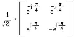
상기 도 20(e)의 매트릭스는 두 입력 데이터 가운데 위상이 90도(


제2인터리버(1940)는 상기 선형 프리코딩부(1930)에서 출력된 심볼 데이터를 다시 인터리빙(interleaving)한다. 상기 제2인터리버(1940)에는 컨벌루션 인터리버(convolution interleaver), 블록 인터리버(block interleaver) 등을 사용할 수 있다. 상기 제2인터리버(1940)는 상기 선형 프리코딩부(1930)에서 출력된 데이터들에 분산되어 있는 심볼 데이터가 동일한 주파수 선택적 페이딩을 겪지 않도록 섞어주는 역할을 하는 것이므로, 그 종류는 송수신 시스템의 구현 예에 따라 달라질 수 있다.The
블록 인터리버를 사용하는 경우 인터리버의 길이는 구현 예에 따라 달라질 수 있다. 인터리버의 길이가 OFDM 심볼 길이보다 작거나 같으면, 인터리빙은 한 OFDM 심볼 내의 영역에서만 이루어지고, 인터리버의 길이가 OFDM 심볼 길이보다 길면, 여러 심볼에 걸쳐서 인터리빙이 이루어질 수 있다.In the case of using the block interleaver, the length of the interleaver may vary depending on implementation. If the length of the interleaver is less than or equal to the OFDM symbol length, interleaving is performed only in an area within one OFDM symbol, and if the length of the interleaver is longer than the OFDM symbol length, interleaving may be performed over several symbols.
도 21은 본 발명에 따른 일 실시예로서, 인터리버의 일 예를 나타낸 도면이다. 상기 도 21의 인터리버는 심볼 길이 N을 갖는 OFDM 시스템에 대한 인터리버의 실시예로서 상기 도 19와 같은 송신 장치의 제2인터리버(1940)에 사용될 수 있다.21 is a diagram illustrating an example of an interleaver according to an embodiment of the present invention. The interleaver of FIG. 21 may be used in the
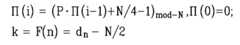
N은 인터리버의 길이를 나타내며, i는 상기 인터리버의 길이만큼의 값 즉, 0에서 N-1까지의 정수 값을 갖는다. n은 송신 시스템에서 유효 전송 캐리어 만큼의 개수를 가진다. ∏(i)는 modulo-N 연산으로 이루어진 순열을 가리키며, dn은 N/2 값 을 제외하고 유효 전송 캐리어 영역에 있는 ∏(i)값을 순서대로 갖는다. k는 실제 전송 캐리어의 인덱스 값을 나타내며, 상기 dn에서 N/2을 빼서 전송 대역폭의 가운데가 DC가 되도록 한다. P는 순열 상수로 구현 예에 따라 달라질 수 있다.N represents the length of the interleaver, i has a value equal to the length of the interleaver, that is, an integer value from 0 to N-1. n has the number of effective transport carriers in the transmission system. ∏ (i) denotes a permutation of modulo-N operations, and dn has values of ∏ (i) in the effective transport carrier region in order except N / 2 values. k represents the index value of the actual transport carrier, so that d / 2 is subtracted from dn so that the center of the transmission bandwidth is DC. P is a permutation constant and may vary depending on the embodiment.
도 22는 본 발명에 따른 일 실시예로서, 도 21의 인터리버의 구체적인 예를 나타낸 도면이다. 상기 도 22의 예는 OFDM 심볼의 길이와 인터리버의 길이(N)는 2048로 설정되었고, 유효 전송 캐리어의 개수는 1536(1792-256)개로 설정되었다.FIG. 22 is a diagram illustrating a specific example of the interleaver of FIG. 21 according to an embodiment of the present invention. In the example of FIG. 22, the length of an OFDM symbol and the length N of an interleaver are set to 2048, and the number of effective transmission carriers is set to 1536 (1792-256).
따라서, i는 0~2047의 정수이고, n은 0~1535의 정수이다. ∏(i)는 modulo-2048 연산으로 이루어진 순열이고, dn은 256≤∏(i)≤1792인 값에 대하여, 1024(N/2)를 제외하고 순서대로 ∏(i)값을 갖는다. k는 상기 dn에서 1024를 뺀 값이다. P는 13을 갖는다.Therefore, i is an integer of 0-2047, n is an integer of 0-1535. ∏ (i) is a permutation of modulo-2048 operations, and dn has a value of ∏ (i) in order except 1024 (N / 2) for a value of 256 ≦ ∏ (i) ≦ 1792. k is a value obtained by subtracting 1024 from dn . P has 13.
상기와 같은 인터리버를 이용하여, 입력되는 데이터(i)에 대응되는 데이터(k)를 출력하므로, 인터리버의 길이(N) 만큼의 데이터에 대하여 순서를 섞어서 전송할 수 있다.Since the data k corresponding to the input data i is output using the interleaver as described above, the data of the length N of the interleaver can be mixed and transmitted.
상기 인터리빙된 데이터는 다중 입출력 인코더(1950)로 출력되며, 상기 다중 입출력 인코더(1950)는 입력된 심볼 데이터를 복수의 전송 안테나에 실리도록 인코딩하여 출력한다. 예를 들어, 두 개의 전송 경로를 갖는 경우, 상기 다중 입출력 인코더(1950)는 프리코딩된 데이터를 제1프레임 형성부(1960) 또는 제2프레임 형성부(1965)로 출력한다.The interleaved data is output to the multiple input /
공간 다이버시티 방식의 경우, 상기 제1프레임 형성부(1960)와 제2프레임 형 성부(1965)로 각각 같은 정보의 데이터가 출력되고, 공간 다중화 방식으로 인코딩한 경우, 상기 제1프레임 형성부(1960)와 제2프레임 형성부(1965)로 각각 다른 데이터가 출력된다.In the case of the spatial diversity method, data of the same information is output to the first
도 23은 본 발명에 따른 일 실시예로서, 다중 입출력 인코딩 방식의 일 예를 나타낸 도면이다. 상기 도 23의 실시예는 다중 입출력 인코딩 방식 가운데 하나인 STBC로 상기 도 19와 같은 송신 장치에 사용될 수 있다. 상기 인코딩 방식은 하나의 예이며, 다른 다중 입출력 인코딩 방식의 적용이 배제되지 않는다.FIG. 23 is a diagram illustrating an example of a multiple input / output encoding scheme according to an embodiment of the present invention. The embodiment of FIG. 23 is STBC, which is one of multiple input / output encoding schemes, and may be used in a transmitting apparatus as shown in FIG. The encoding scheme is one example, and the application of other multiple input / output encoding schemes is not excluded.
상기 STBC 인코더의 예에서 T는 심볼 전송 주기를 나타내며, s는 전송할 입력 심볼을, y는 출력 심볼을 나타낸다. *는 켤레 복소수(complex conjugate)를 나타내며, Tx #1, Tx #2는 각각 전송 안테나 1, 2를 나타낸다.In the example of the STBC encoder, T denotes a symbol transmission period, s denotes an input symbol to be transmitted, and y denotes an output symbol. * Denotes a complex conjugate, and
상기 예에 따르면, 시간 t에서 Tx #1은 s0를, Tx #2는 s1을 전송하고, 시간 t+T에서 Tx #1은 -s1*를, Tx #2는 s0*을 전송한다. 각 전송 안테나에서는 전송 주기 내에서 s0와 s1의 같은 정보의 데이터를 송신한다. 따라서, 상기 인코딩 방식은 공간 다이버시티 방식의 하나임을 알 수 있다.According to the above example, at time
제1프레임 형성부(1960)와 제2프레임 형성부(1965)는 상기 각 수신된 신호를 OFDM(orthogonal frequency division multiplex) 방식으로 변조할 수 있도록 파일럿 신호가 삽입된 프레임을 형성한다.The first
상기 프레임은 한 개의 파일럿 심볼 구간과 M-1개의 데이터 심볼 구간을 포함한다. 상기 도 19의 송신 시스템이 복수 개의 안테나를 사용하여 다중 입출력 인 코딩을 수행하는 경우, 수신측에서 각 전송 경로(path)를 구별할 수 있도록 파이럿 심볼의 구조가 결정되어야 한다.The frame includes one pilot symbol period and M-1 data symbol periods. When the transmission system of FIG. 19 performs multiple input / output encoding using a plurality of antennas, a structure of a pilot symbol should be determined so that each transmission path can be distinguished from a receiving side.
도 24(a)은 본 발명에 따른 일 실시예로서, 파일럿 심볼구간의 구조를 나타낸 도면이다. 상기 도 24(a)의 파일럿 심볼구간의 구조는 도 23과 같이 2개의 전송 경로를 갖도록 다중 입출력 인코딩을 수행하는 경우에 사용될 수 있다.24 (a) is a diagram illustrating the structure of a pilot symbol section according to an embodiment of the present invention. The structure of the pilot symbol section of FIG. 24A may be used when multiple input / output encoding is performed to have two transmission paths as shown in FIG. 23.
상기 도 24(a)의 경우, 두 전송 경로를 구별하기 위해 파일럿 캐리어 정보를 인터리빙시켜 짝수(even), 홀수(odd) 파일럿으로 나눈다. 예를 들어, 파일럿 심볼 구간에 짝수의 파일럿 캐리어 정보를 포함하는 프레임 데이터의 경우 0번 안테나를 통해서 전송하며, 파일럿 심볼 구간에 홀수의 파일럿 캐리어 정보를 포함하는 프레임 데이터의 경우 1번 안테나를 통해서 전송한다. 따라서, 수신측에서는 상기 파일럿 심볼 구간의 해당 캐리어 인덱스를 이용하여 각 전송 경로를 구별할 수 있다.In the case of FIG. 24A, pilot carrier information is interleaved and divided into even and odd pilots to distinguish two transmission paths. For example, frame data including even pilot carrier information in a pilot symbol period is transmitted through
상기 실시예의 경우, 하나의 심볼에서 절반의 서브 캐리어(subcarrier)에 해당하는 채널을 추정할 수 있다. 따라서, 짧은 코히어런스 시간(coherence time)을 갖는 전송 채널에 대해서도 높은 채널 추정(channel estimation) 성능을 얻을 수 있다.In the above embodiment, a channel corresponding to half of subcarriers may be estimated in one symbol. Therefore, high channel estimation performance can be obtained even for a transmission channel having a short coherence time.
도 24(b)는 본 발명에 따른 일 실시예로서, 파일럿 심볼구간의 다른 구조를 나타낸 도면이다. 상기 도 24(b)의 경우에도 도 23과 같이 2개의 전송 경로를 갖도록 다중 입출력 인코딩을 수행하는 경우에 사용될 수 있다.24B is a diagram illustrating another structure of a pilot symbol section according to an embodiment of the present invention. In the case of FIG. 24 (b), the multi-input / output encoding may be used to have two transmission paths as shown in FIG. 23.
상기 도 24(b)의 경우 Hadamard 타입의 파일럿 심볼 구간의 실시예를 나타낸다. 상기 실시 예는 두 전송 경로를 구별하기 위해 심볼 구간 단위로 Hadamard 변 환을 수행한다. 따라서 짝수 심볼 구간에는 각 전송 경로를 위한 두 파일럿 캐리어 정보가 합해진 값을 포함하고, 홀수 심볼 구간에는 두 파일럿 캐리어 정보의 차 값을 포함한다.24 (b) shows an embodiment of a Hadamard type pilot symbol interval. The above embodiment performs Hadamard conversion on a symbol interval basis to distinguish two transmission paths. Accordingly, the even symbol interval includes the sum of two pilot carrier information for each transmission path, and the odd symbol interval includes the difference between two pilot carrier information.
예를 들어, 짝수 심볼 구간에는 0번 안테나를 통해 전송할 파일럿 캐리어 정보(a)와 1번 안테나를 통해 전송할 파일럿 캐리어 정보(b)가 합해진 값(a+b)을 포함하며, 홀수 심볼 구간에는 0번 안테나를 통해 전송할 파일럿 캐리어 정보(a)와 1번 안테나를 통해 전송할 파일럿 캐리어 정보(b)의 차 값(a-b)을 포함한다. 수신측에서는 수신된 파일럿 인덱스를 통해 두 파일럿 캐리어 정보의 합/차를 알고 있는 경우, 각 전송 경로를 구별할 수 있다.For example, the even symbol interval includes a pilot value of a carrier (a) to be transmitted through
상기 실시예의 경우, 모든 서브 캐리어에 해당하는 채널을 추정할 수 있으므로, 각 전송 경로에 대해서 처리할 수 있는 채널의 지연 확산(delay spread)이 심볼 길이만큼 확장될 수 있다.In the above embodiment, since channels corresponding to all subcarriers can be estimated, delay spread of a channel that can be processed for each transmission path can be extended by a symbol length.
상기 도 24(b)의 도면은 상기 두 파일럿 캐리어 정보의 구분이 용이하도록 도시된 것으로, 주파수 영역에서의 두 파일럿 캐리어 정보를 모두 도시하였다. 짝수 심볼 구간과 홀수 심볼 구간 도면의 경우, 두 파일럿 캐리어 정보의 임펄스는 같은 주파수 지점에 위치한다. 짝수 심볼 구간 도면의 경우, 구분의 용이를 위해 0번 안테나를 통해 전송할 파일럿 캐리어 정보와 1번 안테나를 통해 전송할 파일럿 캐리어 정보의 위치를 차이가 나도록 도시한 것이고, 상기 파일럿 캐리어 정보는 같은 주파수 지점에 위치한다.FIG. 24 (b) is a diagram for easily distinguishing the two pilot carrier information and shows both the pilot carrier information in the frequency domain. In the case of the even symbol interval and the odd symbol interval diagram, impulses of two pilot carrier information are located at the same frequency point. In the case of the even-symbol interval diagram, the positions of the pilot carrier information to be transmitted through the
상기 도 24(a)와 24(b)의 실시예는 전송 경로가 2개인 경우의 예이며, 전송 경로가 그 이상인 경우에는 파일럿 캐리어 정보를 홀,짝수가 아닌 전송 경로의 수만큼 구분될 수 있도록 나누거나, 심볼 구간 단위로 Hadamard 변환을 수행할 수 있다.24 (a) and 24 (b) are examples of two transmission paths, and when the transmission path is longer, pilot carrier information may be distinguished by the number of transmission paths, not odd or even. You can divide or perform Hadamard transformation on a symbol interval basis.
제1변조부(1970)와 제2변조부(1975)는 상기 제1프레임 형성부(1960)와 제2프레임 형성부(1965)에서 출력된 데이터들을 각각 OFDM의 부반송파(sub carrier)들에 실어 전송할 수 있도록 변조한다.The
제1전송부(1980)와 제2전송부(1985)는 각각 제1변조부(1970)와 제2변조부(1975)에서 출력된 보호 구간과 데이터 구간을 가진 디지털 형식의 신호를 아날로그 신호로 변환하고, 상기 변환된 아날로그 신호를 송신(transmit)한다.The
도 25는 본 발명에 따른 일 실시예로서, 또 다른 신호 수신 장치를 개략적으로 나타낸 블록도이다. 상기 도 25의 실시예는 다중 입출력 방식에 따라 송신된 신호를 수신하는 수신 장치를 나타낸다. 상기 도 25의 수신 장치는 상기 도 8과 같은 수신 장치에 다중 입출력 방식이 적용된 경우이다.25 is a block diagram schematically illustrating another signal receiving apparatus according to an embodiment of the present invention. 25 illustrates a receiver for receiving a signal transmitted according to a multiple input / output scheme. The receiving device of FIG. 25 is a case where a multiple input / output method is applied to the receiving device of FIG. 8.
도 25의 본 발명에 따른 실시예는 수신부(2500), 동기부(2510), 복조부(2520), 프레임 파싱(parsing)부(2530), 다중 입출력 디코더(2540), 제1디인터리버(deinterleaver)(2550), 선형 프리코딩 디코더(2560), 심볼디맵퍼(2570), 제2디인터리버(2580) 및 순방향 오류정정 복호부(2590)를 포함한다. 상기 도 25의 실시예는 상기 신호 수신 시스템에서 신호가 처리되는 과정을 중심으로 설명한 것으로, 수신 경로의 수가 정해진 것은 아니다.The embodiment according to the present invention of FIG. 25 includes a
수신부(2500)는 수신된 RF 신호의 주파수 대역을 다운 컨버전(down conversion)한 후 디지털 신호로 변환하여 출력한다. 동기부(2510)는 수신부(2500)에서 출력된 수신 신호의 주파수 영역과 시간 영역의 동기를 획득하여 출력한다. 상기 동기부(2510)는 주파수 영역 신호의 동기 획득을 위해 복조부(2520)가 출력하는 데이터의 주파수 영역의 오프셋(offset) 결과를 이용할 수 있다.The
복조부(2520)는 상기 동기부(2510)에서 출력된 수신 데이터를 복조하고, 가드구간을 제거한다. 이를 위해 복조부(2520)는 수신 데이터를 주파수 영역으로 변환시키고, 서브 캐리어(sub carrier)에 분산된 데이터 값을 각각의 부반송파에 할당되었던 값으로 디코딩한다.The
프레임 파싱부(2530)는 상기 복조부(2520)에서 복조된 신호의 프레임 구조에 따라 파일럿 심볼을 제외하고 데이터 심볼 구간의 심볼 데이터를 출력할 수 있다.The
다중 입출력 디코더(2540)는 상기 프레임 파싱부(2530)에서 출력한 데이터를 수신하여 디코딩한 후 하나의 데이터 열을 출력한다. 상기 다중 입출력 디코더(2540)는 상기 도 13의 다중 입출력 인코더(1350)에서 복수의 전송 안테나에 실리도록 인코딩한 방식에 대응되는 방식에 따라 디코딩하여 하나의 데이터 열을 출력한다.The multiple input /
제1디인터리버(2550)는 상기 다중 입출력 디코더(2540)에서 출력된 데이터 열에 대해 디인터리빙(de-interleaving)을 수행하여 데이터를 인터리빙되기 전의 순서로 복원시킨다. 상기 제1디인터리버(2550)는 상기 도 13의 제2인터리버(1340)에서 인터리빙한 방식에 대응되는 방식에 따라 디인터리빙하여 데이터 열의 순서를 복원한다.The
선형 프리코딩 디코더(2560)는 신호 송신 장치에서 데이터를 분산한 과정의 역과정을 수행하여 데이터를 복원한다.The
도 26(a)는 본 발명에 따른 일 실시예로서, 선형 프리코딩 디코더의 예를 개략적으로 나타낸 블록도이다. 상기 선형 프리코딩 디코더(2560)는 직/병렬 변환부(2562), 제1디코딩부(2564) 및 병/직렬 변환부(2566)를 포함한다.FIG. 26A is a block diagram schematically illustrating an example of a linear precoding decoder according to an embodiment of the present invention. The
직/병렬 변환부(2562)는 입력된 데이터를 병렬(parallel) 데이터로 변환한다. 제1디코딩부(2564)는 상기 병렬 데이터를 디코딩 매트릭싱(matrixing)을 통해 분산되어진 데이터들로부터 본래의 데이터를 복원한다. 상기 디코딩을 수행하는 디코딩 매트릭스는 신호 송신 장치의 인코딩 매트릭스의 역 매트릭스(inverse matrix)가 된다. 예를 들어, 상기 신호 송신 장치에서 도 17(a), 17(b), 17(c)와 같은 vanderMonde 매트릭스, Hadamard 매트릭스, Golden code 등을 사용하여 인코딩을 한 경우, 상기 제1디코딩부(2564)는 각각 상기 매트릭스들의 역 매트릭스를 이용하여 분산된 데이터를 본래의 데이터로 복원한다.The serial /
병/직렬 변환부(2566)는 상기 제1디코딩부(2564)에서 수신된 병렬 데이터를 다시 직렬(serial) 데이터로 변환하여 출력한다.The parallel /
도 26(b)는 본 발명에 따른 일 실시예로서, 선형 프리코딩 디코더의 또 다른 일 예를 개략적으로 나타낸 블록도이다. 상기 선형 프리코딩 디코더(2560)는 직/병렬 변환부(2561), 제2디코딩부(2563) 및 병/직렬 변환부(2565)를 포함한다.FIG. 26B is a block diagram schematically illustrating another example of a linear precoding decoder according to an embodiment of the present invention. The
직/병렬 변환부(2561)는 입력된 데이터를 병렬(parallel) 데이터로 변환하고, 병/직렬 변환부(2565)는 상기 제2디코딩부(2563)에서 수신된 병렬 데이터를 다 시 직렬(serial) 데이터로 변환하여 출력한다. 제2디코딩부(2563)는 ML(Maximum Likelihood) 디코딩을 이용하여 상기 직/병렬 변환부(2561)에서 출력된 병렬 데이터에 분산되어 있는 본래의 데이터를 복원하여 출력한다.The serial /
상기 제2디코딩부(2563)는 송신기에서의 전송 방식을 고려한 ML 디코더로서, 수신된 심볼 데이터를 상기 전송 방식에 대응되도록 ML 디코딩하여 상기 병렬 데이터에 분산되어 있는 본래의 데이터를 복원한다. 즉, 상기 ML 디코더는 송신단에서의 인코딩 룰(encoding rule)을 고려하여 수신된 심볼 데이터를 ML 디코딩한다.The second decoder 2603 is an ML decoder considering a transmission scheme in a transmitter, and restores original data distributed in the parallel data by ML decoding the received symbol data to correspond to the transmission scheme. That is, the ML decoder decodes the received symbol data in consideration of an encoding rule at the transmitting end.
도 27(a) 내지 27(c)는 본 발명에 따른 일 실시예로서, 분산된 심볼을 복원시키는 2×2 코드 매트릭스의 일 예를 나타낸 도면이다. 도 27(a) 내지 27(c)의 코드 매트릭스는 상기 도 17(a) 내지 도 17(c)의 인코딩 매트릭스가 아닌 도 20(c) 내지 도 20(e)의 2×2 형태의 인코딩 매트릭스에 대응되는 역 매트릭스이다. 상기 매트릭스는 선형 프리코딩 디코더(2560)의 디코딩부에 입력된 2개의 데이터에 분산되어 있는 데이터를 복원하여 출력한다.27 (a) to 27 (c) are diagrams illustrating an example of a 2x2 code matrix for reconstructing distributed symbols according to an embodiment of the present invention. The code matrix of FIGS. 27 (a) to 27 (c) is not the encoding matrix of FIGS. 17 (a) to 17 (c) but the 2 × 2 encoding matrix of FIGS. 20 (c) to 20 (e). Is the inverse matrix corresponding to. The matrix restores and outputs data dispersed in two pieces of data input to the decoding unit of the
도 27(a)는 본 발명에 따른 일 실시예로서, 2×2 코드 매트릭스의 일 예를 나타낸 도면이다. 상기 도 27(a)의 매트릭스는 상기 도 20(c)의 인코딩 매트릭스에 대응되는 디코딩 매트릭스이다.27 (a) is a diagram illustrating an example of a 2x2 code matrix according to an embodiment of the present invention. The matrix of FIG. 27 (a) is a decoding matrix corresponding to the encoding matrix of FIG. 20 (c).
상기 도 27(a)의 매트릭스는 두 입력 데이터 가운데 위상이 -45도(


도 27(b)는 본 발명에 따른 일 실시예로서, 2×2 코드 매트릭스의 다른 일 예를 나타낸 도면이다. 상기 도 27(b)의 매트릭스는 상기 도 20(d)의 인코딩 매트릭스에 대응되는 디코딩 매트릭스이다.27 (b) is a diagram illustrating another example of a 2 × 2 code matrix according to an embodiment of the present invention. The matrix of FIG. 27 (b) is a decoding matrix corresponding to the encoding matrix of FIG. 20 (d).
상기 도 27(b)의 매트릭스는 0.5를 곱한 첫번째 입력 데이터를 두번째 입력 데이터와 더하여 첫번째 출력 데이터로 출력하며, 첫번째 입력 데이터에서 0.5를 곱한 두번째 입력 데이터를 빼서 두번째 출력 데이터로 출력한다. 그리고 상기 각 출력 데이터는
도 27(c)는 본 발명에 따른 일 실시예로서, 2×2 코드 매트릭스의 다른 일 예를 나타낸 도면이다. 상기 도 27(c)의 매트릭스는 상기 도 20(e)의 인코딩 매트릭스에 대응되는 디코딩 매트릭스이다. 상기 도 27(c)의 '*'는 입력되는 데이터에 대한 켤레 복소수(complex conjugate)를 의미한다.27 (c) is a diagram illustrating another example of a 2 × 2 code matrix according to an embodiment of the present invention. The matrix of FIG. 27C is a decoding matrix corresponding to the encoding matrix of FIG. 20E. '*' In FIG. 27 (c) means a complex conjugate with respect to input data.
상기 도 27(c)의 매트릭스는 위상이 -90도(


심볼디맵퍼(2570)는 상기 선형 프리코딩 디코더(2560)에서 디코딩된 심볼 데이터를 비트열로 복원할 수 있다. 상기 심볼디맵퍼(2570)은 상기에서 설명한 옵티멀 성상 방식의 디맵핑 방식을 이용하여 비트열을 복원한다.The
제2디인터리버(2580)는 상기 심볼디맵퍼(2570)에서 출력된 데이터 열에 대해 디인터리빙(de-interleaving)을 수행하여 데이터를 인터리빙되기 전의 순서로 복원시킨다. 상기 제2디인터리버(2580)는 상기 도 13의 제1인터리버(1310)에서 인터리빙한 방식에 대응되는 방식에 따라 디인터리빙하여 데이터 열의 순서를 복원한다. The
순방향 오류정정 복호부(2590)는 상기 순서가 복원된 데이터를 순방향 오류정정 복호화하여 수신 데이터에 발생한 오류를 검출하고, 상기 오류를 수정할 수 있다.The forward
도 28은 본 발명에 따른 일 실시예로서, 순방향 오류정정 복호부를 개략적으로 나타낸 블록도이다. 상기 순방향 오류정정 복호부(2590)는 도 13의 순방향 오류정정부(1300)에 대응되며, 인너 디코더(inner decoder)와 아웃터 디코더(outer decoder)로서 LDPC 디코더(2592)와 BCH 디코더(2594)를 포함한다.28 is a block diagram schematically illustrating a forward error correction decoding unit according to an embodiment of the present invention. The forward error
LDPC 디코더(2592)는 채널에서 발생한 전송 에러를 검출하여 오류를 정정하고, BCH 디코더(2594)는 상기 LDPC 디코더(2592)에서 디코딩된 데이터의 잔류 오류 를 정정하여 에러 플로어(error floor)를 제거한다.The
도 29는 본 발명에 따른 일 실시예로서, 신호 수신 장치에서 복수의 수신 경로를 갖는 경우를 개략적으로 나타낸 블록도이다. 이하 설명의 편의를 위해 수신 경로가 2개인 경우를 예로 하여 설명한다.29 is a block diagram schematically illustrating a case where a signal receiving apparatus has a plurality of receiving paths according to an embodiment of the present invention. For convenience of explanation, the following description will be given by using two reception paths as an example.
도 29의 실시예는 제1수신부(2900), 제2수신부(2905), 제1동기부(2910), 제2동기부(2915), 제1복조부(2920), 제2복조부(2925), 제1프레임 파싱부(2930), 제2프레임 파싱부(2935), 다중 입출력 디코더(2940), 제3디인터리버(2950), 선형 프리코딩 디코더(2960), 심볼디맵퍼(2970), 제4디인터리버(2980) 및 순방향 오류정정 복호부(2990)를 포함한다.29 illustrates a
제1수신부(2900)와 제2수신부(2905)는 RF 신호를 각각 수신하여, 주파수 대역을 다운 컨버전(down conversion)한 후 디지털 신호로 변환하여 출력한다. 제1동기부(2910)와 제2동기부(2915)는 각각 제1수신부(2900)와 제2수신부(2905)에서 출력된 수신 신호의 주파수 영역과 시간 영역의 동기를 획득하여 출력한다. 상기 제1동기부(2910)와 제2동기부(2915)는 주파수 영역 신호의 동기 획득을 위해 각각 제1복조부(2920)와 제2복조부(2925)가 출력하는 데이터의 주파수 영역의 오프셋(offset) 결과를 이용할 수 있다.The
제1복조부(2920)는 제1동기부(2910)에서 출력된 수신 데이터를 복조한다. 이를 위해 제1복조부(2920)는 수신 데이터를 주파수 영역으로 변환시키고, 서브 캐리어에 분산된 데이터 값을 각각의 부반송파(sub carrier)에 할당되었던 값으로 디코딩한다. 제2복조부(2925)는 제2동기부(2915)에서 출력된 수신 데이터를 복조한다.The
제1프레임 파싱부(2930)와 제2프레임 파싱부(2935)는 각각 제1복조부(2920)와 제2복조부(2925)에서 복조된 신호의 프레임 구조에 따라 수신 경로를 구별하여, 파일럿 심볼을 제외한 데이터 심볼 구간의 심볼 데이터를 출력할 수 있다.The
다중 입출력 디코더(2940)는 상기 제1프레임 파싱부(2930)와 제2프레임 파싱부(2935)에서 각각 출력한 데이터를 수신하여 디코딩한 후 하나의 데이터 열을 출력한다.The multiple input /
도 30은 본 발명에 따른 일 실시예로서, 다중 입출력 디코딩 방식의 일 예를 나타낸 도면이다. 상기 도 30은 송신측에서 STBC 방식으로 다중 입출력 인코딩하여 데이터를 전송한 경우에, 수신측에서의 대응되는 디코딩 예를 나타낸 것으로서 송신측에서 2개의 송신 안테나를 사용한 경우이다. 이는 하나의 예이며 다른 다중 입출력 방식의 적용이 배제되는 것은 아니다.30 is a diagram illustrating an example of a multiple input / output decoding scheme according to an embodiment of the present invention. 30 is a diagram showing an example of a corresponding decoding on the receiving side when the transmitting side transmits data by multiple input / output encoding using the STBC method, and the transmitting side uses two transmitting antennas. This is an example and the application of other multiple input / output methods is not excluded.
상기 수식의 r(k), h(k), s(k), n(k)는 각각 수신측에 수신된 심볼, 채널 응답, 송신측에서 전송한 심볼 값, 채널 잡음(noise)을 나타낸다. 그리고 아래 첨자의 s, i, 0, 1은 각각 s번째 전송 심볼, i번째 수신 안테나, 0번 송신 안테나, 1번 송신 안테나를 나타낸다. '*'는 켤레 복소수(complex conjugate)를 나타낸다. 예를 들어, hs,1,i(k)는 1번 송신 안테나에서 s번째로 전송된 심볼이 i번째 수신 안테나에 수신된 경우, 상기 전송된 심볼이 겪은 채널의 응답을 나타낸다. rs+1,i(k)는 i번째 수신 안테나에 수신된 s+1번째 수신 심볼을 나타낸다.R (k), h (k), s (k), and n (k) in the above equations represent symbols received at the receiver, channel response, symbol values transmitted at the transmitter, and channel noise, respectively. Subscripts s, i, 0, and 1 denote an sth transmission symbol, an ith reception antenna, a 0th transmission antenna, and a 1st transmission antenna, respectively. '*' Represents a complex conjugate. For example, hs, 1, i (k) indicates a response of the channel experienced by the transmitted symbol when the s-th transmitted symbol is received by the i-th reception antenna. rs+ 1, i (k) represents the s + 1 th received symbol received at the i th receive antenna.
상기 도 30의 수식에 따르면, i번째 수신 안테나에 수신된 s번째 수신 심볼 인 rs,i(k)는 0번째 송신 안테나에서 i번째 수신 안테나에 채널을 거쳐 송신된 s번째 심볼 값, 1번째 송신 안테나에서 i번째 수신 안테나에 채널을 거쳐 송신된 s번째 심볼 값, 그리고 상기 각 채널의 채널 잡음의 합(ns(k))을 더한 값이 된다.According to the equation of FIG. 30, rs, i (k), which is the s-th reception symbol received at the i-th reception antenna, is the s-th symbol value transmitted through the channel from the 0th transmission antenna to the i-th reception antenna, and the 1st In the transmitting antenna, the i-th receiving antenna is the sum of the s-th symbol value transmitted through the channel and the sum of the channel noise of each channel (ns (k)).
그리고 i번째 수신 안테나에 수신된 s+1번째 수신 심볼인 rs+1,i(k)는 0번째 송신 안테나에서 i번째 수신 안테나에 채널을 거쳐 송신된 s+1번째 심볼 값, 1번째 송신 안테나에서 i번째 수신 안테나에 채널을 거쳐 송신된 s+1번째 심볼 값, 그리고 상기 각 채널의 채널 잡음의 합(ns(k))을 더한 값이 된다.In addition, rs+ 1, i (k), which is the s + 1 th received symbol received at the i th receive antenna, is the s + 1 th symbol value transmitted through the channel from the 0 th transmit antenna to the i th receive antenna, and the first transmit It is the sum of the s + 1th symbol value transmitted through the channel and the sum of the channel noise of each channel (ns (k)).
도 31은 본 발명에 따른 일 실시예로서, 도 30의 구체적인 예를 나타낸 도면이다. 상기 도 31은 송신측에서 STBC 방식으로 다중 입출력 인코딩하여 데이터를 전송한 경우의 디코딩 예로, 송신측에서 두 개의 전송 안테나를 이용하여 전송하고, 수신측에서 하나의 안테나를 통해 수신한 경우의 디코딩 수식이다. 즉, 하나의 수신 안테나를 이용하여 다중 전송된 데이터를 수신하는 경우이다.31 is a diagram illustrating a specific example of FIG. 30 as an embodiment according to the present invention. 31 is an example of decoding when a transmitter transmits data by performing multiple input / output encoding using the STBC method. The decoding equation when the transmitter transmits two transmitting antennas and the receiver receives one antenna. to be. That is, this is a case of receiving data transmitted by using one receiving antenna.
송신측에서 두 개의 전송 안테나를 이용하고, 수신측에서 하나의 안테나를 이용하는 경우 전송 채널은 2개가 될 수 있다.When two transmitting antennas are used at the transmitting side and one antenna is used at the receiving side, there may be two transmission channels.
상기 수식의 h0, s0는 각각 송신측 0번 안테나로부터 수신안테나까지의 전송 채널 응답, 송신측 0번 안테나에서 전송하는 심볼을 나타내며, h1, s1은 각각 송신측 1번 안테나로부터 수신 안테나까지의 전송 채널 응답, 송신측 1번 안테나에서 전송하는 심볼을 나타낸다. '*'는 켤레 복소수(complex conjugate)를 나타내며, 아 래 식의 s0'와 s1'는 복원된 심볼을 나타낸다.H0 and s0 in the above equations represent the transmission channel response from the transmitting
그리고, r0와 r1은 각각 t시간에 수신 안테나에 수신된 심볼, 전송주기(T)가 지난 t+T시간에 수신 안테나에 수신된 심볼을 나타내며, n0와 n1은 상기 각 수신시간에서 각 전송경로의 채널 잡음이 더해진 값을 나타낸다.And r0 and r1 represent symbols received at the receiving antenna at t time and symbols received at the receiving antenna at t + T time after the transmission period T, respectively, and n0 and n1 are the respective reception times. Denotes the sum of channel noise of each transmission path.
상기 도 31의 수식과 같이 수신 안테나에 수신된 신호는 각 송신 안테나에서 전송한 신호가 각 전송 채널을 겪은 값을 더한 값으로 표현될 수 있다. 그리고 복원된 심볼은 상기 수신된 값과 각 채널 응답값을 이용하여 산출한다.As shown in Equation 31 of FIG. 31, a signal received by a reception antenna may be expressed as a value obtained by adding a value experienced by each transmission channel to a signal transmitted by each transmission antenna. The recovered symbol is calculated using the received value and each channel response value.
이하 다중 입출력 디코더(2940)에서 순방향 오류정정 복호부(2990)까지의 신호 처리 과정은 상기 도 25에서 설명한 바와 동일하다.Hereinafter, the signal processing from the multiple input /
도 32는 본 발명에 따른 일 실시예로서, 신호 송신 방법의 순서를 나타낸 순서도이다.32 is a flowchart illustrating a signal transmission method according to an embodiment of the present invention.
입력된 데이터에 대하여 수신측에서 전송 오류를 발견하고 정정할 수 있도록 순방향 오류정정 부호화 한다(S3200). 예를 들어, 상기 순방향 오류정정 부호화를 위해 인너 인코더로 LDPC 인코딩을 사용할 수 있으며, 에러 플로어를 방지하기 위한 아웃터 인코더로 BCH 인코딩을 사용할 수 있다.Forward error correction encoding is performed on the input data so that the receiving side can detect and correct a transmission error (S3200). For example, LDPC encoding may be used as an inner encoder for the forward error correction encoding, and BCH encoding may be used as an outer encoder for preventing an error floor.
상기 부호화된 데이터에 대해 전송 채널에서의 버스트 에러(burst error)에 강인하도록 인터리빙을 수행하고, 상기 인터리빙된 데이터를 심볼 데이터로 매핑(mapping)한다(S3210). 상기 매핑 방식으로 옵티멀 성상 매핑 방식을 사용할 수 있다.Interleaving is performed on the encoded data so as to be robust to a burst error in a transmission channel, and the interleaved data is mapped to symbol data (S3210). As the mapping method, an optical constellation mapping method may be used.
그리고 상기 심볼 데이터를 채널의 주파수 선택적 페이딩(frequency selective fading)에 강인하도록 하기 위해, 상기 매핑된 심볼 데이터가 주파수 영역에서 여러 개의 출력 심볼에 분산되도록 프리코딩을 수행하고(S3220), 상기 프리코딩된 심볼 데이터를 인터리빙하여(S3230) 출력한다.In order to make the symbol data robust to frequency selective fading of a channel, precoding is performed such that the mapped symbol data is distributed to a plurality of output symbols in a frequency domain (S3220). The symbol data are interleaved (S3230) and output.
따라서, 주파수 선택적인 페이딩 채널을 겪었을 때 모든 정보가 페이딩으로 손실될 확률을 줄이고, 상기 분산된 심볼 데이터가 동일한 주파수 선택적 페이딩을 겪지 않도록 한다. 상기 인터리빙에는 컨벌루션 인터리버, 블록 인터리버 등을 사용할 수 있으며, 이는 구현 예에 따라 선택가능하다.Thus, reducing the likelihood that all information is lost to fading when undergoing a frequency selective fading channel, ensures that the distributed symbol data does not experience the same frequency selective fading. The interleaving may use a convolution interleaver, a block interleaver, etc., which may be selected according to an implementation example.
그리고 상기 인터리빙된 데이터를 전송 프레임으로 변환하고, 이를 변조하여 전송한다(S3240). 예를 들어, 상기 전송 프레임은 파일럿 캐리어 심볼 구간과 데이터 심볼 구간을 포함하며, 파일럿 캐리어 심볼 구간은 전송 경로를 구분할 수 있는 구조를 가질 수 있다.The interleaved data is converted into a transmission frame, modulated, and then transmitted (S3240). For example, the transmission frame may include a pilot carrier symbol interval and a data symbol interval, and the pilot carrier symbol interval may have a structure capable of distinguishing a transmission path.
다만, 단일 입출력 방식이 아닌 다중 입출력 방식의 신호 송수신 시스템에 적용되는 경우에는, 상기 인터리빙된 심볼 데이터를 복수의 안테나를 통해서 전송할 수 있도록 다중 입출력 인코딩하여 전송 프레임으로 변환한다. 상기 안테나의 수는 가능한 데이터 전송 경로의 수가 될 수 있다. 공간 다이버시티 방식의 경우, 각 경로에서는 같은 정보의 데이터를 전송하고, 공간 다중화 방식의 경우, 각 경로에서는 다른 데이터를 전송한다.However, when applied to a signal transmission / reception system of a multiple input / output method instead of a single input / output method, the interleaved symbol data may be multi-input / output encoded to be transmitted through a plurality of antennas and converted into a transmission frame. The number of antennas can be the number of possible data transmission paths. In the case of the spatial diversity method, data of the same information is transmitted in each path, and in the case of the spatial multiplexing method, different data is transmitted in each path.
도 33은 본 발명에 따른 일 실시예로서, 신호 수신 방법의 순서를 나타낸 순서도이다.33 is a flowchart illustrating a signal receiving method according to an embodiment of the present invention.
신호 수신 장치에서는 송신 장치에서 송신된 신호를 수신하여 동기화하고, 프레임 데이터로 복조한다(S3300).The signal receiving apparatus receives and synchronizes a signal transmitted from the transmitting apparatus, and demodulates the frame data (S3300).
상기 복조된 프레임 데이터를 파싱한 후, 파싱된 데이터를 신호 송신 장치에서 인터리빙한 방식의 역으로 디인터리빙한다(S3310). 상기 디인터리빙으로 순서가 복원된 데이터 열을 프리코딩한 방식의 역으로 디코딩하여, 주파수 영역에서 여러 개의 심볼 데이터에 분산되어 있는 원래 심볼 데이터를 복원한다(S3320).After parsing the demodulated frame data, the parsed data is deinterleaved in the reverse of the interleaved method in the signal transmission apparatus (S3310). The data sequence of which the order is restored by the deinterleaving is decoded in the inverse of the precoding scheme, thereby restoring original symbol data dispersed in a plurality of symbol data in the frequency domain (S3320).
상기 복원된 심볼 데이터를 디매핑(de-mapping)하여 대응되는 비트 데이터로 복원하고, 상기 비트 데이터를 디인터리빙하여 원래의 순서로 복원한다(S3330). 예를 들어, 상기 디매핑 방식으로 옵티멀 성상 방식에 따른 디매핑 방식을 사용할 수 있다.De-mapping the recovered symbol data to restore the corresponding bit data, and deinterleaving the bit data to restore the original bit data in the original order (S3330). For example, a demapping method according to an optical constellation method may be used as the demapping method.
그리고 상기 순서가 복원된 데이터에 대해 순방향 오류정정 복호를 수행하여 전송 에러를 탐지하고 에러를 정정한다(S3340). 예를 들어, 상기 순방향 오류정정 복호화를 위해 LDPC 디코딩을 사용할 수 있으며, 에러 플로어를 방지하기 위한 아웃터 디코더로 BCH 디코딩을 사용할 수 있다.Then, forward error correction decoding is performed on the data whose order is restored, thereby detecting a transmission error and correcting the error (S3340). For example, LDPC decoding may be used for the forward error correction decoding, and BCH decoding may be used as an outer decoder for preventing an error floor.
다만, 단일 입출력 방식이 아닌 다중 입출력 방식의 신호 송수신 시스템에 적용되는 경우에는, 상기 파싱된 프레임 데이터를 다중 입출력 디코딩한 후에 상기 디코딩된 데이터를 디인터리빙한다. 이 경우, 수신된 데이터의 전송 경로를 구분하여 다중 입출력 디코딩한다.However, when applied to a signal transmission / reception system using a multiple input / output method instead of a single input / output method, the decoded data is deinterleaved after multiple input / output decoding of the parsed frame data. In this case, the transmission path of the received data is divided to perform multiple input / output decoding.
상기 신호 송수신 방법 및 신호 송수신 장치는 상기 예에 한정되지 않으며, 방송이나 통신 등의 모든 신호 송수신 시스템에 적용될 수 있다.The signal transceiving method and the signal transceiving apparatus are not limited to the above examples, and may be applied to all signal transceiving systems such as broadcasting or communication.
본 발명은 상술한 실시예에 한정되지 않으며, 첨부된 청구범위에서 알 수 있는 바와 같이 본 발명이 속한 분야의 통상의 지식을 가진 자에 의해 변형이 가능하고 이러한 변형은 본 발명의 범위에 속한다.The present invention is not limited to the above-described embodiments, and as can be seen in the appended claims, modifications can be made by those skilled in the art to which the invention pertains, and such modifications are within the scope of the present invention.
이상에서 설명한 바와 같이 본 발명의 신호 송수신 방법 및 신호 송수신 장치에 따르면, 기존의 신호 송수신 네트워크 망을 이용하여 제안된 신호 송수신 시스템으로의 전환이 용이하며, 비용을 절감할 수 있는 효과가 있다.As described above, according to the signal transmission / reception method and the signal transmission / reception apparatus of the present invention, it is easy to switch to the proposed signal transmission / reception system using an existing signal transmission / reception network network, and the cost can be reduced.
또한, SNR 이득을 바탕으로 데이터 전송률을 향상시킬 수 있고, 긴 지연 확산을 갖는 전송 채널에 대해서 채널 추정이 가능하게 되어 신호 송신 거리를 증가시킬 수 있는 효과가 있다. 따라서, 전체적인 송수신 시스템의 신호 송수신 성능을 높일 수 있는 효과가 있다.In addition, the data rate can be improved based on the SNR gain, and channel estimation can be performed for a transmission channel having a long delay spread, thereby increasing the signal transmission distance. Therefore, there is an effect that can increase the signal transmission and reception performance of the overall transmission and reception system.
Claims (16)
Translated fromKoreanPriority Applications (2)
| Application Number | Priority Date | Filing Date | Title |
|---|---|---|---|
| KR1020070052841AKR20080105355A (en) | 2007-05-30 | 2007-05-30 | Method for signal transmitting and apparatus for the same, method for signal receiving and apparatus for the same |
| PCT/KR2008/003054WO2008147138A1 (en) | 2007-05-30 | 2008-05-30 | Method of transmitting and receiving a signal and apparatus for transmitting and receiv0ing a signal |
Applications Claiming Priority (1)
| Application Number | Priority Date | Filing Date | Title |
|---|---|---|---|
| KR1020070052841AKR20080105355A (en) | 2007-05-30 | 2007-05-30 | Method for signal transmitting and apparatus for the same, method for signal receiving and apparatus for the same |
Publications (1)
| Publication Number | Publication Date |
|---|---|
| KR20080105355Atrue KR20080105355A (en) | 2008-12-04 |
Family
ID=40075286
Family Applications (1)
| Application Number | Title | Priority Date | Filing Date |
|---|---|---|---|
| KR1020070052841AWithdrawnKR20080105355A (en) | 2007-05-30 | 2007-05-30 | Method for signal transmitting and apparatus for the same, method for signal receiving and apparatus for the same |
Country Status (2)
| Country | Link |
|---|---|
| KR (1) | KR20080105355A (en) |
| WO (1) | WO2008147138A1 (en) |
Families Citing this family (2)
| Publication number | Priority date | Publication date | Assignee | Title |
|---|---|---|---|---|
| CN102282845B (en)* | 2009-01-14 | 2014-12-17 | Lg电子株式会社 | Apparatus for transmitting and receiving a signal and method of transmitting and receiving a signal |
| US10826619B2 (en)* | 2016-12-22 | 2020-11-03 | Technische Universität München | Methods of converting or reconverting a data signal and method and system for data transmission and/or data reception |
Family Cites Families (4)
| Publication number | Priority date | Publication date | Assignee | Title |
|---|---|---|---|---|
| KR100556467B1 (en)* | 1998-12-26 | 2006-05-25 | 엘지전자 주식회사 | Method and apparatus for demapping |
| KR100539862B1 (en)* | 2001-04-04 | 2005-12-28 | 삼성전자주식회사 | Method and apparatus for transporting and receiving data in cdma mobile system |
| US7394865B2 (en)* | 2003-06-25 | 2008-07-01 | Nokia Corporation | Signal constellations for multi-carrier systems |
| EP1667349A4 (en)* | 2003-09-30 | 2011-03-02 | Panasonic Corp | TRANSMISSION DEVICE AND METHOD, AND RECOVERY DEVICE |
- 2007
- 2007-05-30KRKR1020070052841Apatent/KR20080105355A/ennot_activeWithdrawn
- 2008
- 2008-05-30WOPCT/KR2008/003054patent/WO2008147138A1/enactiveApplication Filing
Also Published As
| Publication number | Publication date |
|---|---|
| WO2008147138A1 (en) | 2008-12-04 |
Similar Documents
| Publication | Publication Date | Title |
|---|---|---|
| KR100921465B1 (en) | Digital broadcast signal transceiver and control method thereof | |
| KR100921464B1 (en) | Digital broadcast signal transceiver and control method thereof | |
| JP5237290B2 (en) | Method for transmitting a stream of data in a wireless system having at least two antennas and transmitter implementing the method | |
| EP3033879B1 (en) | Apparatus for transmitting broadcast signals, apparatus for receiving broadcast signals, method for transmitting broadcast signals and method for receiving broadcast signals | |
| KR20080095809A (en) | Signal transmitting and receiving method and signal transmitting and receiving device | |
| US10237590B2 (en) | Apparatus for transmitting broadcast signals, apparatus for receiving broadcast signals, method for transmitting broadcast signals and method for receiving broadcast signals | |
| KR20080105356A (en) | Signal transmitting and receiving method and signal transmitting and receiving device | |
| KR20080106135A (en) | Signal transmitting and receiving method and signal transmitting and receiving device | |
| KR20080106133A (en) | Signal transmitting and receiving method and signal transmitting and receiving device | |
| KR20080094192A (en) | Signal transmitting and receiving method and signal transmitting and receiving device | |
| KR20080105355A (en) | Method for signal transmitting and apparatus for the same, method for signal receiving and apparatus for the same | |
| EP2191625A2 (en) | Method of transmitting and receiving a signal and apparatus for transmitting and receiving a signal | |
| KR20080094632A (en) | Signal transmitting and receiving method and signal transmitting and receiving device | |
| WO2009002069A2 (en) | Method of transmitting and receiving a signal and apparatus for transmitting and receiving a signal | |
| KR20080094193A (en) | Signal transmitting and receiving method and signal transmitting and receiving device | |
| KR20080106134A (en) | Signal transmitting and receiving method and signal transmitting and receiving device | |
| KR20090032060A (en) | Signal transmitting and receiving method and signal transmitting and receiving device | |
| KR20090031703A (en) | Signal transmitting and receiving method and signal transmitting and receiving device | |
| WO2009002135A2 (en) | Method of transmitting and receiving a signal and apparatus for transmitting and receiving a signal | |
| KR20080090707A (en) | Signal transmitting and receiving method and signal transmitting and receiving device | |
| KR20080094189A (en) | Signal transmitting and receiving method and signal transmitting and receiving device | |
| KR20080094190A (en) | Signal transmitting and receiving method and signal transmitting and receiving device | |
| WO2008123715A1 (en) | Method for signal transmitting and apparatus for the same, method for signal receiving and apparatus for the same | |
| KR20080086728A (en) | Signal transmitting and receiving method and signal transmitting and receiving device |
Legal Events
| Date | Code | Title | Description |
|---|---|---|---|
| PA0109 | Patent application | Patent event code:PA01091R01D Comment text:Patent Application Patent event date:20070530 | |
| PG1501 | Laying open of application | ||
| PC1203 | Withdrawal of no request for examination | ||
| WITN | Application deemed withdrawn, e.g. because no request for examination was filed or no examination fee was paid |