KR20080104977A - Ruled line forming device and corrugated cardboard sheet making machine - Google Patents
Ruled line forming device and corrugated cardboard sheet making machineDownload PDFInfo
- Publication number
- KR20080104977A KR20080104977AKR1020080048895AKR20080048895AKR20080104977AKR 20080104977 AKR20080104977 AKR 20080104977AKR 1020080048895 AKR1020080048895 AKR 1020080048895AKR 20080048895 AKR20080048895 AKR 20080048895AKR 20080104977 AKR20080104977 AKR 20080104977A
- Authority
- KR
- South Korea
- Prior art keywords
- ruled line
- pressing portion
- corrugated
- roll
- sheet
- Prior art date
- Legal status (The legal status is an assumption and is not a legal conclusion. Google has not performed a legal analysis and makes no representation as to the accuracy of the status listed.)
- Granted
Links
Images


Classifications
- B—PERFORMING OPERATIONS; TRANSPORTING
- B31—MAKING ARTICLES OF PAPER, CARDBOARD OR MATERIAL WORKED IN A MANNER ANALOGOUS TO PAPER; WORKING PAPER, CARDBOARD OR MATERIAL WORKED IN A MANNER ANALOGOUS TO PAPER
- B31F—MECHANICAL WORKING OR DEFORMATION OF PAPER, CARDBOARD OR MATERIAL WORKED IN A MANNER ANALOGOUS TO PAPER
- B31F1/00—Mechanical deformation without removing material, e.g. in combination with laminating
- B31F1/08—Creasing
- B31F1/10—Creasing by rotary tools
- B—PERFORMING OPERATIONS; TRANSPORTING
- B31—MAKING ARTICLES OF PAPER, CARDBOARD OR MATERIAL WORKED IN A MANNER ANALOGOUS TO PAPER; WORKING PAPER, CARDBOARD OR MATERIAL WORKED IN A MANNER ANALOGOUS TO PAPER
- B31B—MAKING CONTAINERS OF PAPER, CARDBOARD OR MATERIAL WORKED IN A MANNER ANALOGOUS TO PAPER
- B31B50/00—Making rigid or semi-rigid containers, e.g. boxes or cartons
- B31B50/25—Surface scoring
- B31B50/254—Surface scoring using tools mounted on belts or chains
- B—PERFORMING OPERATIONS; TRANSPORTING
- B31—MAKING ARTICLES OF PAPER, CARDBOARD OR MATERIAL WORKED IN A MANNER ANALOGOUS TO PAPER; WORKING PAPER, CARDBOARD OR MATERIAL WORKED IN A MANNER ANALOGOUS TO PAPER
- B31F—MECHANICAL WORKING OR DEFORMATION OF PAPER, CARDBOARD OR MATERIAL WORKED IN A MANNER ANALOGOUS TO PAPER
- B31F2201/00—Mechanical deformation of paper or cardboard without removing material
- B31F2201/07—Embossing
- B31F2201/0707—Embossing by tools working continuously
Landscapes
- Engineering & Computer Science (AREA)
- Mechanical Engineering (AREA)
- Making Paper Articles (AREA)
- Machines For Manufacturing Corrugated Board In Mechanical Paper-Making Processes (AREA)
Abstract
Description
Translated fromKorean본 발명은 골판지 시트의 표면에 골심지의 골을 따라 괘선 가공을 실시하는 골판지 시트의 괘선 형성 장치 및 이 골판지 시트의 괘선 형성 장치가 적용되는 골판지 시트용 제함기에 관한 것이다.The present invention relates to a ruler forming apparatus of a corrugated sheet which performs ruled line processing along the valley of corrugated cardboard on the surface of the corrugated sheet, and a cardboard sheet making machine to which the ruler forming apparatus of the corrugated sheet is applied.
일반적인 골판지 시트용 제함기는 한 쌍의 라이너 사이에 물결 형상을 이루는 골심지가 풀 부착된 골판지 시트를 가공함으로써 골판지 상자를 제조하는 것으로, 급지부(給紙部)와 인쇄부와 슬로터 크리저부(slotter creaser part)와 폴딩부와 카운터 이젝터부로 구성되어 있다.The corrugator sheet for general corrugated sheet manufactures a corrugated box by processing a corrugated corrugated sheet having a corrugated corrugated shape formed between a pair of liners. The corrugated sheet is made of a paper feeding part, a printing part, and a slotter creaser part. ) And folding unit and counter ejector unit.
급지부는 테이블 상에 적층된 골판지 시트를 크랭크 레버에 의해 작동하는 키커(kicker)에 의해 차내어, 피드 롤에 의해 일정 속도로 골판지 시트를 사이에 끼워 인쇄부로 보내는 것이다.The paper feeding unit takes out the corrugated sheet stacked on the table by a kicker operated by a crank lever, and sandwiches the corrugated sheet at a constant speed by a feed roll to the printing unit.
인쇄부는 1색 또는 다색의 인쇄를 행하는 것으로, 1개 또는 복수의 인쇄 유닛을 갖고 있다. 이 인쇄 유닛에는 인쇄 실린더가 설치되고, 이 실린더에 인쇄판이 설치되어 있다. 이 인쇄 실린더의 근방에 인쇄판에 접촉하는 잉크 공급 롤이 설치되고, 이 잉크 공급 롤의 근방에 인쇄 잉크를 저장하는 잉크 챔버가 설치되어 있다. 잉크 공급 롤의 표면에는 잉크 챔버로부터 잉크가 공급되고, 이 잉크가 인쇄판으로 전이된다. 또한, 인쇄 실린더의 하방에 수용 롤이 설치되어 있고, 골판지 시트는 인쇄판과 수용 롤 사이에 끼워진 상태에서 인쇄가 행해진다.The printing unit prints one color or multiple colors, and has one or a plurality of printing units. A printing cylinder is provided in this printing unit, and a printing plate is provided in this cylinder. An ink supply roll in contact with the printing plate is provided in the vicinity of the printing cylinder, and an ink chamber for storing printing ink is provided in the vicinity of the ink supply roll. Ink is supplied from the ink chamber to the surface of the ink supply roll, and the ink is transferred to the printing plate. Moreover, the accommodating roll is provided below the printing cylinder, and a corrugated sheet is printed in the state sandwiched between a printing plate and the accommodating roll.
슬로터 크리저부는 인쇄가 종료된 골판지 시트에 대해 제1 괘선 롤 및 제2 괘선 롤에 의해 괘선 형성 가공을 실시하는 동시에, 괘선 형성 가공이 실시된 골판지 시트에 대해 슬로터 나이프에 의해 홈 형성 가공을 실시하는 것이다.The slotter crease unit performs ruled line forming processing by the first ruled line roll and the second ruled line roll on the finished corrugated cardboard sheet, and performs groove forming process by the slotter knife on the corrugated sheet on which the ruled line forming process is performed. It is.
폴딩부는 골판지 시트를 이동시키면서 풀 부착 장치에 의해 풀칠 부분에 풀을 도포한다. 그리고, 풀이 도포된 골판지 시트를 계속해서 이동시키면서 절첩 바아 및 절첩 벨트에 의해 절첩하는 동시에, 풀칠 부분을 접착함으로써, 골판지 상자를 제조하는 것이다. 그리고, 카운터 이젝터부는 골판지 시트가 절첩되어 풀 부착되어 제조된 골판지 상자를 호퍼부에 적층하여 소정 매수의 뱃치(batch)로 분류한 후, 소정 매수의 뱃치로 하여 배출하는 것이다.The folding part applies paste to the portion to be pasted by the paste attaching device while moving the corrugated sheet. And a cardboard box is manufactured by fold | folding with a folding bar and a folding belt, continuing to move the paste | coated cardboard sheet | seat apply | coated, and bonding a paste part. Then, the counter ejector unit stacks the cardboard box manufactured by folding the corrugated cardboard sheet and is attached to the hopper unit, classifies the batch into a predetermined number of batches, and discharges the resultant as a batch of predetermined number of sheets.
이와 같이 구성된 골판지 시트용 제함기에서, 슬로터 크리저부는 폴딩부에서 골판지 시트를 절첩하기 위해 필요한 괘선을 형성하는 것으로, 구동 회전 가능한 괘선 롤과, 이 괘선 롤에 대향하는 수용 롤을 갖고 있다. 괘선 롤은 괘선 축에 고정되어 있고, 외주부에 괘선 중심 위치에 대응하는 돌기부가 둘레 방향을 따라 형성되는 동시에, 이 돌기부의 양측에 압박부가 둘레 방향을 따라 형성되어 있다. 따라서, 반송되는 골판지 시트에 대해 괘선 롤과 수용 롤이 끼움 지지함으로써, 괘선 롤의 돌기부에 의해 골심지의 골을 따라 괘선이 형성되는 동시에, 압박부에 의 해 이 괘선의 양측에 오목부가 형성된다. 그로 인해, 폴딩부에서는 골판지 시트를 오목부에 의해 괘선을 따라 적정하게 절첩할 수 있다.In the corrugated sheet sheet making machine configured as described above, the slotter riser portion forms a ruled line necessary for folding the corrugated sheet in the folding portion, and includes a ruled line roll which can be driven and rotated, and a receiving roll facing the ruled line roll. The ruled line roll is fixed to the ruled line axis, and a protrusion corresponding to the ruled line center position is formed along the circumferential portion at the outer circumferential portion, and pressing portions are formed along the circumferential direction on both sides of the protrusion. Therefore, the ruled line roll and the accommodation roll are sandwiched with respect to the conveyed corrugated sheet, whereby ruled lines are formed along the valleys of the corrugated core by the protrusions of the ruled line rolls, and recesses are formed on both sides of the ruled line by the pressing section. Therefore, in a folding part, a corrugated sheet can be appropriately folded along a ruled line by a recessed part.
또한, 이와 같은 골판지 시트의 괘선 형성 장치로서는, 하기 특허문헌 1, 특허문헌 2에 기재된 것이 있다.Moreover, as ruled line formation apparatus of such a corrugated cardboard sheet, there exist some described in following
[특허문헌 1] 일본 특허 출원 공개 제2001-328181호 공보[Patent Document 1] Japanese Patent Application Laid-Open No. 2001-328181
[특허문헌 2] 일본 특허 출원 공개 제2005-035076호 공보[Patent Document 2] Japanese Patent Application Laid-Open No. 2005-035076
그런데, 골판지 시트는 표면 라이너와 이면 라이너 사이에 물결형을 이루는 골심지가 풀 부착되어 형성되어 있지만, 사용하는 목적에 따라서 이 구성이 다르다. 예를 들어, 골심지에 있어서의 골의 높이나 피치, 사용하는 표면 라이너와 이면 라이너와 골심지의 두께나 종이질, 표면 라이너와 이면 라이너 사이에 끼인 골심지의 매수 등에 의해 골판지 시트의 강도가 바뀌게 된다.By the way, although the corrugated sheet is formed by full-corrugating corrugated core between the front liner and the back liner, this configuration differs depending on the purpose of use. For example, the strength of the corrugated sheet is changed by the height and pitch of the valleys in the corrugated core, the thickness and the paper quality of the surface liner and the back liner and the corrugator to be used, and the number of corrugated cores sandwiched between the surface liner and the back liner.
상술한 골판지 시트용 제함기로 고품질의 골판지 상자를 제조하기 위해서는, 소정 위치에서 적정하게 절첩할 필요가 있고, 그것을 위해서는 괘선을 정확한 위치에 강하게 형성할 필요가 있다. 그로 인해, 슬로터 크리저부에서는 괘선 롤에 있어서의 압박부의 폭을 골판지 시트의 강도에 따라서 설정하고 있다. 즉, 강도가 높은 골판지 시트에 대해서는, 압박부의 폭을 넓게 함으로써 괘선의 양측에 폭이 넓은 오목부를 형성하여, 절첩할 때에 괘선을 중심으로 한 그 양측 부분(내측의 복부)의 상호 간섭을 억제하여 접음 정밀도 불량을 방지하고 있다. 한편, 강도가 낮은 골판지 시트에 대해서는, 압박부의 폭을 좁게 함으로써 괘선의 양측에 폭이 좁은 오목부를 형성하여, 절첩 위치를 일정하게 하여 괘선 위치에서 확실하게 접어 접음 정밀도 불량을 방지하고 있다.In order to manufacture a high quality corrugated cardboard box with the above-mentioned cardboard sheet making machine, it is necessary to fold it appropriately at a predetermined position, and for that purpose, it is necessary to strongly form a ruled line at the correct position. Therefore, in the slotter creamer part, the width | variety of the press part in a ruled line roll is set according to the intensity | strength of a corrugated sheet. That is, for a high strength corrugated sheet, by widening the width of the pressing portion, wide concave portions are formed on both sides of the ruled line, and when folded, the mutual interference between the two side portions (inner abdomen) centered on the ruled line is suppressed. This prevents poor folding accuracy. On the other hand, for a corrugated sheet having a low strength, narrow widths of the pressing portions are provided to form narrow recesses on both sides of the ruled line, to make the folding position constant, and to fold it securely at the ruled line position to prevent poor folding accuracy.
그런데, 골판지 시트용 제함기를 이용하여 골판지 시트를 골판지 상자로 가공하고 있을 때, 골판지 시트의 강도에 맞게 괘선 롤을 교환하기 위해서는, 골판지 시트용 제함기를 도중에 정지해야만 하고, 이 정지 시간이 길어져 작업 효율이 저 하되어 버리는 문제가 있다. 그로 인해, 괘선 롤에 있어서의 압박부의 폭을 강도가 높은 골판지 시트에 적합한 폭과 강도가 낮은 골판지 시트에 적합한 폭의 중간 폭으로 설정하여 대처해야 한다. 따라서, 종래의 골판지 시트용 제함기에서는 강도가 높은 골판지 시트에 대해 압박부에 의해 형성되는 오목부의 폭이 불충분해지는 한편, 강도가 낮은 골판지 시트에 대해 오목부의 폭이 지나치게 넓어져, 절첩 위치를 불균일하게 하여 접음 정밀도가 저하되어 버리는 문제가 있다.By the way, when the corrugated sheet is processed into a corrugated cardboard box using the corrugated cardboard sheet maker, in order to replace the ruled line roll in accordance with the strength of the corrugated cardboard sheet, the corrugated cardboard sheet making machine must be stopped in the middle, and this stop time is lengthened. There is a problem of being lowered. Therefore, the width | variety of the press part in a ruled line roll must be set to the width | variety suitable for the high strength corrugated cardboard sheet, and the medium width of the width suitable for the low strength corrugated cardboard sheet, and coping. Therefore, in the conventional cardboard sheet making machine, the width of the recess formed by the pressing portion is insufficient for the corrugated sheet with high strength, while the width of the recess is too wide for the corrugated sheet with low strength, resulting in uneven folding positions. There is a problem that the folding accuracy is lowered.
본 발명은 상술한 과제를 해결하는 것으로, 골판지 시트의 성질에 관계없이 절첩 위치를 균일화하여 절첩 정밀도를 향상시킴으로써 고품질의 골판지 상자를 제조 가능하게 하는 골판지 시트의 괘선 형성 장치 및 골판지 시트용 제함기를 제공하는 것을 목적으로 한다.SUMMARY OF THE INVENTION The present invention solves the above problems, and provides a ruler for forming a corrugated sheet and a corrugator for a corrugated sheet, which enable manufacturing a high quality corrugated cardboard box by improving the folding accuracy by uniformizing the folding position regardless of the properties of the corrugated sheet. It aims to do it.
상기의 목적을 달성하기 위한 청구항 1의 발명의 골판지 시트의 괘선 형성 장치는 괘선 중심 위치에 대응하는 돌기부와 상기 돌기부의 폭 방향의 양측에 위치하는 압박부가 외주부에 둘레 방향을 따라 설치되는 괘선 롤을 갖고, 상기 괘선 롤에 의해 한 쌍의 라이너 사이에 물결 형상을 이루는 골심지가 풀 부착된 골판지 시트에 대해, 상기 골심지의 골을 따라 괘선을 형성하는 골판지 시트의 괘선 형성 장치에 있어서, 상기 압박부는 폭 방향의 길이가 다른 제1 압박부와 제2 압박부를 갖고, 상기 돌기부의 양측에 상기 제1 압박부와 상기 제2 압박부가 대향하여 설치되는 동시에, 상기 제1 압박부와 상기 제2 압박부가 둘레 방향으로 교대로 설치되는 것을 특징으로 하는 것이다.Ruled line forming apparatus of the corrugated sheet of the invention of
또한, 청구항 2의 발명의 골판지 시트의 괘선 형성 장치는 괘선 중심 위치에 대응하는 돌기부와 상기 돌기부의 폭 방향의 양측에 위치하는 압박부가 외주부에 둘레 방향을 따라 설치되는 괘선 롤을 갖고, 상기 괘선 롤에 의해 한 쌍의 라이너 사이에 물결 형상을 이루는 골심지가 풀 부착된 골판지 시트에 대해 상기 골심지의 골을 따라 괘선을 형성하는 골판지 시트의 괘선 형성 장치에 있어서, 상기 압박부는 폭 방향의 곡률이 다른 제1 압박부와 제2 압박부를 갖고, 상기 돌기부의 양측에 상기 제1 압박부와 상기 제2 압박부가 대향하여 설치되는 동시에, 상기 제1 압박부와 상기 제2 압박부가 둘레 방향으로 교대로 설치되는 것을 특징으로 하는 것이다.In addition, the ruled line forming device of the corrugated sheet of the invention of claim 2 has a ruled portion corresponding to the ruled line center position and a ruled line roll which is provided on both sides of the width direction of the protrusion in a circumferential portion is provided along the circumferential direction, the ruled line roll In the ruler forming apparatus of the corrugated sheet of the corrugated sheet forming a ruled line along the valley of the corrugated core with respect to the corrugated sheet of the corrugated sheet that is formed in a wave shape between the pair of liners, the pressing portion is made of a different curvature in the width direction It has a 1st press part and a 2nd press part, The said 1st press part and the said 2nd press part are provided in opposing sides of the said projection part, and the said 1st press part and the said 2nd press part are alternately installed in a circumferential direction. It is characterized by.
청구항 3의 발명의 골판지 시트의 괘선 형성 장치에서는, 상기 괘선 롤은 상기 돌기부와 상기 돌기부의 양측에 제1 설치부 및 제2 설치부가 형성되어 회전축에 고정되는 롤 본체와, 상기 제1 압박부가 형성되어 상기 롤 본체에 있어서의 상기 제1 설치부에 고정되는 제1 압박편과, 상기 제2 압박부가 형성되어 상기 롤 본체에 있어서의 상기 제2 설치부에 고정되는 제2 압박편을 갖는 것을 특징으로 하고 있다.In the ruled line forming device of the corrugated sheet of claim 3, the ruled line roll includes a roll main body having a first mounting portion and a second mounting portion formed on both sides of the protrusion and the protrusion, and fixed to a rotating shaft, and the first pressing portion. And a second pressing piece fixed to the first mounting portion in the roll body, and the second pressing portion formed and fixed to the second mounting portion in the roll body. I am doing it.
청구항 4의 발명의 골판지 시트의 괘선 형성 장치에서는, 상기 롤 본체는 둘레 방향으로 2분할되고, 상기 압박부는 둘레 방향으로 복수 분할됨으로써 상기 제1 압박편과 상기 제2 압박편이 교대로 배치되는 것을 특징으로 하고 있다.In the ruled line forming device of the corrugated cardboard sheet of claim 4, the roll main body is divided into two in the circumferential direction, and the first pressing piece and the second pressing piece are alternately arranged by plurally dividing the pressing part in the circumferential direction. I am doing it.
청구항 5의 발명의 골판지 시트의 괘선 형성 장치에서는, 상기 괘선 롤의 외주부에는 상기 골판지 시트의 길이에 대해 적어도 상기 제1 압박부와 상기 제2 압박부가 형성되는 것을 특징으로 하고 있다.In the ruled line forming device of the corrugated sheet of the fifth aspect, at least the first pressing portion and the second pressing portion are formed on the outer circumferential portion of the ruled roll with respect to the length of the corrugated sheet.
청구항 6의 발명의 골판지 시트용 제함기는, 적층된 골판지 시트를 1매씩 송출하는 급지부와, 상기 골판지 시트의 표면에 인쇄를 실시하는 인쇄부와, 상기 골판지 시트의 표면에 골심지의 골을 따라 괘선 가공을 실시하는 동시에, 이 괘선을 따라 소정 길이의 홈 가공을 실시하는 슬로터 크리저부와, 상기 골판지 시트를 절첩하여 골판지 상자를 형성하는 폴딩부와, 상기 골판지 상자를 적층하여 소정 매수마다 배출하는 카운터 이젝터부를 구비한 골판지 시트용 제함기에 있어서, 슬로터 크리저부는 괘선 중심 위치에 대응하는 돌기부와 상기 돌기부의 폭 방향의 양측에 위치하는 압박부가 외주부에 둘레 방향을 따라 설치되는 괘선 롤을 갖고, 상기 압박부는 폭 방향의 길이 또는 곡률이 다른 제1 압박부와 제2 압박부를 갖고, 상기 돌기부의 양측에 상기 제1 압박부와 상기 제2 압박부가 대향하여 설치되는 동시에, 상기 제1 압박부와 상기 제2 압박부가 둘레 방향으로 교대로 설치되는 것을 특징으로 하는 것이다.The cardboard sheet making machine according to the invention of claim 6 includes a paper feeding unit for feeding the laminated corrugated sheets one by one, a printing unit for printing on the surface of the corrugated sheet, and ruled line processing along the ribs of the corrugated sheet on the surface of the corrugated sheet. At the same time, the slot ejector for performing groove processing of a predetermined length along this ruled line, a folding unit for folding the corrugated sheet to form a cardboard box, and a counter ejector for stacking the corrugated cardboard box and discharging them for each predetermined number of sheets In the cardboard sheet making machine provided with a portion, the slotter riser portion has a projection portion corresponding to a ruled line center position and a pressing portion located at both sides in the width direction of the projection portion, and a ruled line roll having a peripheral portion provided along the circumferential direction. It has the 1st press part and 2nd press part in which the length or curvature of a width direction differs, First pressing portion and the second at the same time being provided opposite second pressing portion for, it is characterized in that the installation in the first pressing portion and the second pressing portion in the circumferential direction alternately.
청구항 1의 발명의 골판지 시트의 괘선 형성 장치에 따르면, 괘선 중심 위치에 대응하는 돌기부와 이 돌기부의 폭 방향의 양측에 위치하는 압박부가 외주부에 둘레 방향을 따라 설치되는 괘선 롤을 갖고, 압박부로서 폭 방향의 길이가 다른 제1 압박부와 제2 압박부를 설치하고, 돌기부의 양측에 제1 압박부와 제2 압박부를 대향하여 설치하는 동시에, 이 제1 압박부와 제2 압박부를 둘레 방향으로 교대로 설치하고 있다. 따라서, 골판지 시트에 대해 괘선 롤에 의해 괘선 형성 가공을 실시할 때, 돌기부에 의해 괘선이 형성되는 동시에, 제1 압박부와 제2 압박부에 의해 그 괘선의 양측에 오목부가 형성되지만, 이때 괘선의 양측에 폭이 넓은 오목부와 폭이 좁은 오목부가 대향하여 형성되는 동시에, 괘선의 길이 방향으로 폭이 넓은 오목부와 폭이 좁은 오목부가 교대로 형성된다. 그로 인해, 골판지 시트를 이 괘선을 따라 절첩할 때, 괘선에 인접하는 복부끼리의 간섭이 방지되는 동시에, 절첩 위치가 한쪽측으로 치우치는 것이 억제되게 되어 골판지 시트의 성질에 관계없이 절첩 위치를 균일화할 수 있고, 그 결과 절첩 정밀도를 향상시킬 수 있다.According to the ruled line forming device of the corrugated sheet of the invention of
또한, 청구항 2의 발명의 골판지 시트의 괘선 형성 장치에 따르면, 괘선 중심 위치에 대응하는 돌기부와 이 돌기부의 폭 방향의 양측에 위치하는 압박부가 외주부에 둘레 방향을 따라 설치되는 괘선 롤을 갖고, 압박부로서 폭 방향의 곡률이 다른 제1 압박부와 제2 압박부를 설치하고, 돌기부의 양측에 제1 압박부와 제2 압박부를 대향하여 설치하는 동시에, 이 제1 압박부와 제2 압박부를 둘레 방향으로 교대로 설치하고 있다. 따라서, 골판지 시트에 대해 괘선 롤에 의해 괘선 형성 가공을 실시할 때, 돌기부에 의해 괘선이 형성되는 동시에, 제1 압박부와 제2 압박부에 의해 그 괘선의 양측에 오목부가 형성되지만, 이때 괘선의 양측에 폭이 넓은 오목부와 폭이 좁은 오목부가 대향하여 형성되는 동시에, 괘선의 길이 방향으로 폭이 넓은 오목부와 폭이 좁은 오목부가 교대로 형성된다. 그로 인해, 골판지 시트를 이 괘선을 따라 절첩할 때, 괘선에 인접하는 복부끼리의 간섭이 방지되는 동시에, 절첩 위치가 한쪽측으로 치우치는 것이 억제되게 되어 골판지 시트의 성질에 관계없이 절첩 위치를 균일화할 수 있고, 그 결과 절첩 정밀도를 향상시킬 수 있다.Moreover, according to the ruled line forming apparatus of the corrugated sheet of the invention of claim 2, the protrusion corresponding to the ruled line center position and the pressing portions located on both sides in the width direction of the protrusion have ruled line rolls provided along the circumferential direction in the outer peripheral portion, The first pressing portion and the second pressing portion having different curvatures in the width direction are provided as the portion, and the first pressing portion and the second pressing portion are provided on both sides of the projection portion so as to face each other, and the circumferential portion of the first pressing portion and the second pressing portion It is installed alternately in the direction. Therefore, when a ruled line forming process is performed with a ruled line roll on the corrugated sheet, ruled lines are formed by the projections, and recesses are formed on both sides of the ruled lines by the first pressing section and the second pressing section. A wide concave portion and a narrow concave portion are formed opposite to each other at the same time, and a wide concave portion and a narrow concave portion are alternately formed in the longitudinal direction of the ruled line. Therefore, when the corrugated sheet is folded along this ruled line, interference between the abdomen adjacent to the ruled line is prevented, and the folded position is suppressed from being biased to one side, so that the folded position can be made uniform regardless of the properties of the corrugated sheet. As a result, the folding accuracy can be improved.
청구항 3의 발명의 골판지 시트의 괘선 형성 장치에 따르면, 괘선 롤은, 돌 기부와 이 돌기부의 양측에 제1 설치부 및 제2 설치부가 형성되어 회전축에 고정되는 롤 본체와, 제1 압박부가 형성되어 롤 본체에 있어서의 제1 설치부에 고정되는 제1 압박편과, 제2 압박부가 형성되어 롤 본체에 있어서의 제2 설치부에 고정되는 제2 압박편에 의해 구성되므로, 괘선 롤에 있어서의 돌기부의 양측에 폭 방향의 길이 또는 곡률이 다른 제1 압박부와 제2 압박부를 용이하게 형성할 수 있어, 가공성을 향상시킬 수 있는 동시에, 하강 코스트를 저감시킬 수 있다.According to the ruled line forming device of the corrugated sheet of the invention of claim 3, the ruled line roll includes a roll main body and a roll main body formed on both sides of the protrusion and the protrusion and fixed to the rotating shaft, and a first pressing portion. And the first pressing piece fixed to the first mounting part in the roll body and the second pressing part is formed and fixed to the second mounting part in the roll body, The first pressing portion and the second pressing portion, which have different lengths or curvatures in the width direction, can be easily formed on both sides of the protruding portion, so that the workability can be improved and the lowering cost can be reduced.
청구항 4의 발명의 골판지 시트의 괘선 형성 장치에 따르면, 롤 본체를 둘레 방향으로 2분할하고, 압박부를 둘레 방향으로 복수 분할함으로써 제1 압박편과 제2 압박편을 교대로 배치하므로, 회전축에의 롤 본체의 장착성을 향상시킬 수 있는 동시에, 괘선 롤의 외주부에 둘레 방향을 따라 폭 방향의 길이 또는 곡률이 다른 제1 압박부와 제2 압박부를 용이하게 교대로 형성할 수 있어, 가공성을 향상시킬 수 있는 동시에, 하강 코스트를 저감시킬 수 있다.According to the ruled line forming device of the corrugated cardboard sheet of claim 4, the roll main body is divided into two in the circumferential direction, and the first pressing piece and the second pressing piece are alternately arranged by plurally dividing the pressing part in the circumferential direction. While the mountability of the roll body can be improved, the first pressing portion and the second pressing portion having different lengths or curvatures in the width direction along the circumferential direction can be easily formed alternately along the circumferential portion of the ruled line roll, thereby improving workability. At the same time, the lowering cost can be reduced.
청구항 5의 발명의 골판지 시트의 괘선 형성 장치에 따르면, 괘선 롤의 외주부에 골판지 시트의 길이에 대해 적어도 제1 압박부와 제2 압박부를 형성하므로, 괘선의 길이 방향으로 폭이 넓은 오목부와 폭이 좁은 오목부를 교대로 형성할 수 있어 절첩 위치를 균일화할 수 있다.According to the ruled line forming device of the corrugated sheet of claim 5, since at least a first pressing portion and a second pressing portion are formed at the outer circumference of the ruled line roll with respect to the length of the corrugated sheet, the recesses and the width wide in the longitudinal direction of the ruled line This narrow recess can be formed alternately, and the folding position can be made uniform.
청구항 6의 발명의 골판지 시트용 제함기에 따르면, 급지부와 인쇄부와 슬로터 크리저부와 폴딩부와 카운터 이젝터부로 구성하고, 슬로터 크리저부는 괘선 중심 위치에 대응하는 돌기부와 이 돌기부의 폭 방향의 양측에 위치하는 압박부를 외주부에 둘레 방향을 따라 설치되는 괘선 롤을 갖고, 압박부로서 폭 방향의 길이 또 는 곡률이 다른 제1 압박부와 제2 압박부를 설치하고, 돌기부의 양측에 제1 압박부와 제2 압박부를 대향하여 설치하는 동시에, 이 제1 압박부와 제2 압박부를 둘레 방향으로 교대로 설치하고 있다. 따라서, 골판지 시트에 대하여 괘선 롤에 의해 괘선 형성 가공을 실시할 때, 돌기부에 의해 괘선이 형성되는 동시에, 제1 압박부와 제2 압박부에 의해 그 괘선의 양측에 오목부가 형성되지만, 이때 괘선의 양측에 폭이 넓은 오목부와 폭이 좁은 오목부가 대향하여 형성되는 동시에, 괘선의 길이 방향으로 폭이 넓은 오목부와 폭이 좁은 오목부가 교대로 형성된다. 그로 인해, 골판지 시트를 이 괘선을 따라 절첩할 때, 괘선에 인접하는 복부끼리의 간섭이 방지되는 동시에, 절첩 위치가 한쪽측으로 치우치는 것이 억제되고, 골판지 시트의 성질에 관계없이 절첩 위치를 균일화할 수 있어 절첩 정밀도를 향상시킬 수 있고, 그 결과 고품질의 골판지 상자를 제조할 수 있다.According to the cardboard sheet making machine of the invention of claim 6, it comprises a paper feeding part, a printing part, a slotter creamer part, a folding part and a counter ejector part, wherein the slotter creamer part is provided on both sides of the projection part corresponding to the ruled line position and the width direction of the projection part. The pressing part to be located has a ruled line roll provided in the outer peripheral part along the circumferential direction, and it is provided as the pressing part and the 1st pressing part and 2nd pressing part from which the width direction or curvature of a width direction differs, and the 1st pressing part and the both sides of a projection part are provided, respectively. At the same time, the second pressing portion is provided to face each other, and the first pressing portion and the second pressing portion are alternately provided in the circumferential direction. Therefore, when a ruled line forming process is performed with a ruled line roll on the corrugated sheet, ruled lines are formed by the projections, and recesses are formed on both sides of the ruled lines by the first pressing portion and the second pressing portion. A wide concave portion and a narrow concave portion are formed opposite to each other at the same time, and a wide concave portion and a narrow concave portion are alternately formed in the longitudinal direction of the ruled line. Therefore, when the corrugated sheet is folded along this ruled line, interference between the abdomen adjacent to the ruled line is prevented, while the folded position is suppressed from one side, and the folded position can be made uniform regardless of the properties of the corrugated sheet. Thereby, the folding accuracy can be improved, and as a result, a high quality cardboard box can be manufactured.
이하에 첨부 도면을 참조하여, 본 발명에 관한 골판지 시트의 괘선 형성 장치 및 골판지 시트용 제함기의 적합한 실시예를 상세하게 설명한다. 또, 이 실시예에 의해 본 발명이 한정되는 것은 아니다.EMBODIMENT OF THE INVENTION Below, with reference to an accompanying drawing, preferred embodiment of the ruled line formation apparatus of the corrugated sheet, and the paper box machine for corrugated sheet which concerns on this invention is described in detail. In addition, this invention is not limited by this Example.
도1은 본 발명의 일 실시예에 관한 골판지 시트의 괘선 형성 장치를 나타내는 개략도, 도2는 본 실시예의 골판지 시트의 괘선 형성 장치에 있어서의 괘선 롤의 정면도, 도3은 본 실시예의 골판지 시트의 괘선 형성 장치에 있어서의 괘선 롤의 이면도, 도4는 도2의 IV-IV 단면도, 도5는 도2의 V-V 단면도, 도6은 본 실시예의 골판지 시트의 괘선 형성 장치에 있어서의 괘선 롤의 측면도, 도7은 본 실시예 의 골판지 시트용 제함기의 개략 구성도, 도8은 가공 전의 골판지 시트의 사시도, 도9는 괘선 및 홈 형성 가공 후의 골판지 시트의 사시도, 도10은 절첩 상태를 나타내는 골판지 시트의 사시도, 도11a 내지 도11e는 본 실시예의 골판지 시트용 제함기에 의한 골판지 시트의 가공 공정을 나타내는 단면도이다.1 is a schematic diagram showing a ruled line forming apparatus of a corrugated sheet according to an embodiment of the present invention, FIG. 2 is a front view of a ruled line roll in a ruled line forming apparatus of a corrugated sheet of the present embodiment, and FIG. 3 is a corrugated sheet of the present embodiment. Fig. 4 is a IV-IV cross section of Fig. 2, Fig. 5 is a VV cross-sectional view of Fig. 2, and Fig. 6 is a ruled line roll in the ruler forming apparatus of the corrugated sheet of the present embodiment. 7 is a schematic configuration diagram of the cardboard sheet making machine of this embodiment, FIG. 8 is a perspective view of a corrugated sheet before processing, FIG. 9 is a perspective view of a corrugated sheet after ruled line and groove forming processing, and FIG. 10 is a folded state. 11A to 11E are cross-sectional views showing the processing steps of the corrugated cardboard sheet by the cardboard sheet making machine of this embodiment.
본 실시예의 골판지 시트의 괘선 형성 장치가 적용된 골판지 시트용 제함기는 도7에 도시한 바와 같이 골판지 시트(S)를 가공함으로써 골판지 상자(B)를 제조하는 것으로, 급지부(11)와 인쇄부(12)와 슬로터 크리저부(골판지 시트의 괘선 형성 장치)(13)와 폴딩부(14)와 카운터 이젝터부(15)로 구성되어 있다. 이 골판지 시트(S)는 표면 라이너와 이면 라이너 사이에 물결형을 이루는 골심지가 풀 부착되어 형성된 것이지만, 사용하는 목적에 따라서 골심지에 있어서의 골의 높이나 피치, 표면 라이너와 이면 라이너와 골심지의 두께나 종이질, 표면 라이너와 이면 라이너 사이에 끼인 골심지의 매수 등에 의해 그 강도가 다르다.Corrugated cardboard sheet making machine to which the ruled line forming device of the corrugated sheet of the present embodiment is applied is to manufacture a cardboard box (B) by processing the corrugated cardboard sheet (S), as shown in Figure 7, the
급지부(11)에서, 테이블(21) 상에 다수매의 골판지 시트(S)가 적층되어 있고, 크랭크 레버 기구(22)에 의해 왕복 운동하는 키커(23)가 그 최하위에 있는 골판지 시트(S)를 1매씩 차내어 상하 한 쌍의 피드 롤(24)에 송출할 수 있다. 이 상하의 피드 롤(24)은 일정 속도로 회전하고 있어, 키커(23)에 의해 차내어진 골판지 시트(S)를 사이에 끼워 인출하여 인쇄부(12)로 보낼 수 있다.In the
인쇄부(12)는 4색의 인쇄를 행하기 위해 4개의 인쇄 유닛(31, 32, 33, 34)이 설치되어 있고, 4개의 잉크 색(예를 들어, 시안, 마젠타, 옐로, 블랙)을 사용하여 인쇄를 행할 수 있다. 각 인쇄 유닛(31, 32, 33, 34)은 대략 동일한 구성을 이루 고, 인쇄 실린더(35)와 잉크 공급 롤(36)과 잉크 챔버(37)와 수용 롤(38)을 갖고 있다. 인쇄 실린더(35)는 외주부에 인쇄판(39)이 설치되어 있고, 이 인쇄 실린더(35)의 근방에 인쇄판(39)에 접촉하는 잉크 공급 롤(36)이 설치되어 있고, 이 잉크 공급 롤(36)의 근방에 잉크를 저장하는 잉크 챔버(37)가 설치되어 있다. 또한, 인쇄 실린더(35)의 하방에 대향하여 수용 롤(38)이 설치되어 있다.The
따라서, 인쇄 유닛(31)에서, 잉크 공급 롤(36)의 표면에는 잉크 챔버(37)로부터 잉크가 공급되어 있고, 인쇄 실린더(35) 및 잉크 공급 롤(36)이 동기 회전하면, 잉크 공급 롤(36)의 잉크가 인쇄판(39)으로 전이되고, 인쇄 실린더(35)와 수용 롤(38) 사이에 골판지 시트(S)가 반송되면, 이 골판지 시트(S)가 인쇄판(39)[인쇄 실린더(35)]과 수용 롤(38)에 의해 끼움 지지된 상태에서 그 표면에 인쇄가 실시된다. 또한, 인쇄 실린더(35) 및 수용 롤(38)의 하류측에는 상하 한 쌍의 이송 롤(40)이 설치되어 있고, 이 이송 롤(40)에 의해 골판지 시트(S)가 다음의 인쇄 유닛(32)으로 반송된다.Therefore, in the
슬로터 크리저부(13)는 골판지 시트(S)에 대해 괘선 가공을 실시하는 동시에 홈 형성 가공을 실시하는 것이다. 이 슬로터 크리저부(13)에서, 상하 한 쌍의 롤 축(41, 42)에는 상부 괘선 헤드(43), 하부 괘선 헤드(괘선 롤)(44)가 고정되어 있고, 이 상부 괘선 헤드(43) 및 하부 괘선 헤드(44)는 동기 회전 가능하게 되어 있다. 또한, 상하 한 쌍의 슬로터 축(45, 46)에는 상부 슬로터 헤드(47), 하부 슬로터 헤드(48)가 고정되어 있고, 이 상부 슬로터 헤드(47) 및 하부 슬로터 헤드(48)는 동기 회전 가능하게 되어 있다. 그리고, 이 괘선 헤드(43, 44)와 슬로터 헤 드(47, 48) 사이에는 상하 한 쌍의 반송 롤(49, 50)이 설치되어 있고, 동기 회전 가능하게 되어 있다.The
이 상부 괘선 헤드(43) 및 하부 괘선 헤드(44)는 그 사이에 반송된 골판지 시트(S)에 대해 그 표면에 괘선을 형성하는 것으로, 상세한 것은 후술한다. 한편, 상부 슬로터 헤드(47) 및 하부 슬로터 헤드(48)는 그 사이에 반송된 골판지 시트(S)에 대해 홈 형성 가공을 행함으로써, 상부 슬로터 헤드(47)의 외주부에 2개의 슬로터 나이프(47a)가 고정되어 있다. 또한, 이 상부 괘선 헤드(43) 및 하부 괘선 헤드(44), 상부 슬로터 헤드(47) 및 하부 슬로터 헤드(48)는 축 방향으로 복수, 본 실시예에서는 4세트 설치되어 있다.The upper ruled
폴딩부(14)는 골판지 시트(S)를 이동하면서 풀칠하는 부분에 풀을 도포한 후, 절첩하여 접착함으로써 골판지 상자(B)를 제조하는 것이다. 이 폴딩부(14)에서, 골판지 시트(S)의 반송 방향을 따라 가이드 레일(51)이 배치되는 동시에, 이 가이드 레일(51)의 상방에 반송 벨트(52)가 순환 가능하게 설치되어 있다. 그리고, 가이드 레일(51) 및 반송 벨트(52)를 따라 풀 부착 장치(53), 절첩 바아(54), 절첩 벨트(55)가 배치되어 있다.The
따라서, 홈이나 풀칠 부분이 형성된 골판지 시트(S)는 폴딩부(14)에서 가이드 레일(51) 및 반송 벨트(52)에 지지되어 이동하면서, 풀 부착 장치(53)에 의해 풀칠 부분에 풀이 도포된 후, 절첩 바아(54)에 의해 절첩된다. 이 절첩이 180도 근방까지 진행되면, 또한 절첩 벨트(52)가 작용하여 절첩력이 강해지고, 상하의 송출 롤(56)에 의해 풀칠 부분이 꽉 압박되어 접착이 확실하게 된 후 송출된다.Accordingly, the corrugated sheet S in which the grooves or paste portions are formed is supported by the
카운터 이젝터부(15)는 골판지 시트(S)가 풀 부착되어 절첩되어 제조된 골판지 상자(B)를 적층하여 소정 매수의 뱃치로 분류한 후 배출하는 것으로, 호퍼 장치(61)를 갖고 있다. 이 호퍼 장치(61)는 승강 가능한 엘리베이터(62)와 전방 맞댐판(63)과 모서리 정렬판(64)을 갖고 있고, 엘리베이터(62)의 하방에 반출 컨베이어(65)가 배치되어 있다.The
따라서, 골판지 상자(B)가 상하의 송출 롤(56)에 의해 송출되면, 이 골판지 상자(B)는 선단부가 전방 맞댐판(63)에 접촉하여 수평 방향의 이동이 정지되고 하방으로 낙하하여 엘리베이터(62) 상에 적층되는 동시에, 모서리 정렬판(64)에 의해 어긋남이 보정된다. 그리고, 호퍼 장치(61)에 소정수의 골판지 상자(B)가 적층되면, 엘리베이터(62)가 하강하여, 이 엘리베이터(62) 상의 상자 뱃치[소정수의 골판지 상자(B)]를 반출 컨베이어(65) 상에 옮기고, 이 반출 컨베이어(65)에 의해 상자 뱃치가 다음의 공정으로 보내진다.Therefore, when the cardboard box B is sent out by the upper and lower delivery rolls 56, the cardboard box B is displaced downward by stopping the horizontal movement when the tip part contacts the
이와 같이 구성된 골판지 시트용 제함기의 슬로터 크리저부(13)는, 도1에 도시한 바와 같이 상하 한 쌍의 롤 축(41, 42)에 장착된 상부 괘선 헤드(43) 및 하부 괘선 헤드(44)와, 상하 한 쌍의 슬로터 축(45, 46)에 장착된 상부 슬로터 헤드(47) 및 하부 슬로터 헤드(48)와, 상하 한 쌍의 반송 롤(49, 50)로 구성되어 있다.As shown in FIG. 1, the
본 실시예에서, 하부 괘선 헤드(44)는 외주부에 괘선 중심 위치에 대응하여 돌기부가 설치되는 동시에, 이 돌기부의 폭 방향의 양측에 각각 압박부(제1 압박부, 제2 압박부)가 설치되어 있고, 골판지 시트(S)에 대해 돌출부에 의해 골심지의 골을 따라 괘선을 형성하는 동시에, 이 괘선의 양측에 압박부에 의해 오목부를 형 성할 수 있다. 그리고, 이 제1, 제2 압박부는 폭 방향의 길이 및 곡률이 달라, 돌기부의 양측에 대향하여 설치되는 동시에, 둘레 방향으로 교대로 설치되어 있다.In the present embodiment, the lower ruled
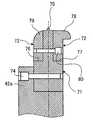
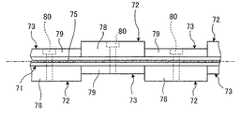
즉, 하부 괘선 헤드(44)는 도2 내지 도6에 도시한 바와 같이 2개의 헤드 본체(롤 본체)(71)와, 8개의 제1 압박편(72)과, 8개의 제2 압박편(73)으로 구성되어 있다. 이 헤드 본체(71)는 둘레 방향으로 2분할된 반원 부재가 링 형상으로 연결되어 구성되어 있고, 하부 롤 축(42)에 일체로 형성된 플랜지부(42a)에 체결 볼트(74)에 의해 고정되어 있다. 또한, 헤드 본체(71)는 외주부에 돌기부(75)가 둘레 방향의 전체 둘레에 걸쳐서 형성되는 동시에, 이 돌기부(75)의 폭 방향에 있어서의 양측에 제1 설치부(76) 및 제2 설치부(77)가 형성되어 있다.That is, the lower ruled
제1 압박편(72)은 폭 방향의 길이가 길고 또한 폭 방향의 곡률이 작은 제1 압박부(78)가 형성되어 있고, 헤드 본체(71)의 제1 설치부(76) 또는 제2 설치부(77)에 끼워 맞춤하고 있다. 또한, 제2 압박편(73)은 폭 방향의 길이가 짧고 또한 폭 방향의 곡률이 큰 제2 압박부(79)가 형성되어 있고, 헤드 본체(71)의 제1 설치부(76) 또는 제2 설치부(77)에 끼워 맞춤하고 있다. 그리고, 제1 압박편(72) 제1 설치부(76) 또는 제2 설치부(77)에 끼워 맞춤하고, 또한 제2 압박편(73)이 제1 설치부(76) 또는 제2 설치부(77)에 끼워 맞춤한 상태에서, 체결 볼트(80)가 제1 압박편(72)과 헤드 본체(71)와 제2 압박편(73)을 관통하여 체결됨으로써, 각 압박편(72, 73)이 헤드 본체(71)에 고정된다.The
이 경우, 전술한 바와 같이, 제1 압박편(72)[제1 압박부(78)]과 제2 설치부(77)[제2 압박편(73)]는 돌기부(75)의 양측에 대향하도록 헤드 본체(71)의 제1 설치부(76)와 제2 설치부(77)에 고정되는 동시에, 둘레 방향으로 교대로 고정되어 있다. 즉, 도4에 도시한 바와 같이 헤드 본체(71)의 제1 설치부(76)에 제1 압박편(72)이 고정되고 제2 설치부(77)에 제2 압박편(73)이 고정된 부분에서는, 하부 괘선 헤드(44)의 폭 방향 한쪽측에 폭이 넓고 곡률이 작은 제1 압박부(78)가 위치하고, 폭 방향 다른 쪽측에 폭이 좁고 곡률이 큰 제2 설치부(77)가 위치하게 된다. 그리고, 도5에 도시한 바와 같이 헤드 본체(71)의 제1 설치부(76)에 제2 압박편(73)이 고정되고, 제2 설치부(77)에 제1 압박편(72)이 고정된 부분에서는, 하부 괘선 헤드(44)의 폭 방향 한쪽측에 폭이 넓고 곡률이 작은 제1 압박부(78)가 위치하고, 폭 방향 다른 쪽 측에 폭이 좁고 곡률이 큰 제2 설치부(77)가 위치하게 된다. 즉, 하부 괘선 헤드(44)의 압박부(78, 79)가 폭 방향으로 2분할되는 동시에, 둘레 방향으로 8분할되게 된다.In this case, as mentioned above, the 1st press piece 72 (1st press part 78) and the 2nd mounting part 77 (2nd press piece 73) oppose the both sides of the
또한, 상술한 바와 같이, 하부 괘선 헤드(44)는 헤드 본체(71)의 둘레 방향으로 제1 압박편(72)과 제2 압박편(73)이 교대로 고정되어 있고, 골판지 시트의 길이에 대해 적어도 이 제1 압박편(72)[제1 압박부(78)]과 제2 압박편(73)[제2 압박부(79)]이 형성되어 있다. 즉, 하부 괘선 헤드(44)가 회전하여 골판지 시트(S)의 표면에 돌출부(75)에 의해 괘선을 형성하는 동시에, 이 괘선의 양측에 각 압박부(78, 79)에 의해 오목부를 형성하지만, 골판지 시트의 반송 방향에 대해 이 각 압박부(78, 79)에 의해 형성되는 각 오목부가 적어도 각각 1개씩 형성되도록 제1 압박편(72)[제1 압박부(78)]과 제2 압박편(73)[제2 압박부(79)]에 있어서의 둘레 방향의 길이, 즉 분할 개수가 설정되어 있다.In addition, as described above, the lower ruled
또한, 상부 괘선 헤드(43)는 하부 괘선 헤드(44)의 상방에 대향하여 배치되어 있고, 외주부에 도시하지 않은 우레탄이 고정되어 있다.Moreover, the upper ruled
여기서, 본 실시예의 골판지 시트용 제함기에 의한 골판지 상자의 제조 방법에 대해 설명한다.Here, the manufacturing method of the cardboard box by the corrugator for cardboard sheets of a present Example is demonstrated.
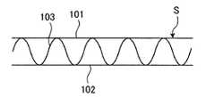
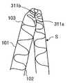
골판지 시트(S)는 도8 및 도11a에 도시한 바와 같이 표면 라이너(101)와 이면 라이너(102) 사이에 물결형을 이루는 골심지(103)가 풀로 부착되어 형성되어 있고, 전공정에서 2개의 접음선(201, 202)이 형성되어 있다. 이 골판지 시트(S)는 도7에 도시한 바와 같이 급지부(11)에 적층되어 있고, 크랭크 레버 기구(22)에 의해 왕복 운동하는 키커(23)가 그 최하위에 있는 골판지 시트(S)를 1매씩 차내어, 피드 롤(24)이 이 골판지 시트(S)를 사이에 끼워 인출하고, 인쇄부(12)로 송출한다. 그리고, 인쇄부(12)에서 4개의 인쇄 유닛(21, 22, 23, 24)에 의해 4개의 잉크 색을 사용하여 골판지 시트(S)의 표면에 인쇄가 실시된다.As shown in FIGS. 8 and 11A, the corrugated sheet S is formed by a corrugated
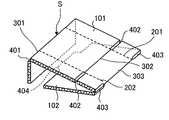
인쇄부(12)에서 인쇄가 실시된 골판지 시트(S)는 이송 롤(40)에 의해 슬로터 크리저부(13)로 보내진다. 이 슬로터 크리저부(13)에서는 골판지 시트(S)에 대해 괘선 가공을 실시하는 동시에 홈 형성 가공을 실시한다. 도1 내지 도6에 도시한 바와 같이, 이 슬로터 크리저부(13)에서 골판지 시트(S)는 상하의 상부 괘선 헤드(43)와 하부 괘선 헤드(44) 사이를 통과할 때에, 그 이면, 즉 이면 라이너(102)측에 하부 괘선 헤드(44)의 돌기부(75)에 의해 괘선(301, 302, 303, 304)(도9 참조)이 형성되는 동시에, 이 괘선(301, 302, 303, 304)의 양측에 오목부(311a, 311b, 312a, 312b, 313a, 313b, 314a, 314b)(도9 참조)가 형성된다.The corrugated cardboard sheet S which has been printed in the
이때, 본 실시예의 하부 괘선 헤드(44)는 돌기부(75)의 양측에 대향하여 제1 압박부(78)와 제2 압박편(73)이 대향하여 형성되는 동시에, 이 제1 압박부(78)와 제2 압박편(73)이 둘레 방향으로 교대로 형성되어 있다. 그로 인해, 도9 및 도11b, 도11c에 도시한 바와 같이 골판지 시트(S)는 이면 라이너(102)측에 각 괘선(301, 302, 303, 304)의 양측에 다른 폭의 오목부(311a, 311b, 312a, 312b, 313a, 313b, 314a, 314b)가 형성된다. 즉, 골판지 시트(S)의 이면 라이너(102)측에는, 돌기부(75)에 의해 형성된 괘선(301, 302, 303, 304)의 한쪽측에 제1 압박부(78)에 의해 형성된 폭이 넓은 오목부(311a, 312a, 313a, 314a)가 형성되고, 돌기부(75)에 의해 형성된 괘선(301, 302, 303, 304)의 다른 쪽측에 제2 압박편(73)에 의해 형성된 폭이 좁은 오목부(311b, 312b, 313b, 314b)가 형성된다. 그리고, 이 폭이 넓은 오목부(311a, 312a, 313a, 314a)와 폭이 좁은 오목부(311b, 312b, 313b, 314b)는 골판지 시트(S)의 반송 방향에 대해 교대로 형성된다.At this time, the lower ruled
상하의 상부 괘선 헤드(43)와 하부 괘선 헤드(44)에 의해 골판지 시트(S)에 괘선(301, 302, 303, 304)과 오목부(311a, 311b, 312a, 312b, 313a, 313b, 314a, 314b)가 형성되면, 도1에 도시한 바와 같이 이 골판지 시트(S)는 반송롤(49, 50)에 의해 반송된다. 그리고, 골판지 시트(S)는 상하의 상부 슬로터 헤드(47)와 하부 슬로터 헤드(48) 사이를 통과할 때에, 상부 슬로터 헤드(47)의 슬로터 나이프(47a)에 의해 홈(401, 402, 403)(도9 참조)이 형성되는 동시에, 풀칠 부분(404)(도9 참조)이 형성된다.Ruled
그리고, 슬로터 크리저부(13)에서 괘선 형성 가공 및 홈 형성 가공이 실시된 골판지 시트(S)는 폴딩부(14)로 보내지고, 여기서 절첩 가공이 실시되어 골판지 상자(B)가 제조된다. 즉, 골판지 시트(S)는 도7 및 도10에 도시한 바와 같이 가이드 레일(51) 및 반송 벨트(52)에 지지되어 이동하고, 풀 부착 장치(53)에 의해 풀칠 부분(404)에 풀이 도포된 후, 절첩 바아(54) 및 절첩 벨트(55)에 의해 절첩되어 풀칠 부분(404)이 접착된다.And the corrugated cardboard sheet S in which the ruler shaping process and the groove forming process were performed in the
이때, 골판지 시트(S)에는 괘선(301, 302, 303, 304)이 형성되는 동시에, 그 한쪽측에 폭이 넓은 오목부(311a, 312a, 313a, 314a)가 형성되고, 그 다른 쪽측에 폭이 좁은 오목부(311b, 312b, 313b, 314b)가 형성되고, 또한 폭이 넓은 오목부(311a, 312a, 313a, 314a)와 폭이 좁은 오목부(311b, 312b, 313b, 314b)가 반송 방향으로 교대로 형성되어 있다.At this time, ruled
그로 인해, 골판지 시트(S)는 폴딩부(14)에 의해 절첩될 때, 도11d 및 도11e에 도시한 바와 같이 폭이 넓은 오목부(311a, 312a, 313a, 314a)와 폭이 좁은 오목부(311b, 312b, 313b, 314b)가 잘 맞물려 복부끼리의 간섭이 방지된다. 또한, 골판지 시트(S)는 폭이 넓은 오목부(311a, 312a, 313a, 314a)와 폭이 좁은 오목부(311b, 312b, 313b, 314b)의 맞물림 관계가 골판지 시트(S)의 길이 방향으로 교대로 되므로, 골판지 시트(S)에 있어서의 절첩 위치가 괘선(301, 302, 303, 304)으로부터 어긋나는 것이 억제된다.Therefore, when the corrugated sheet S is folded by the folding
폴딩부(14)에서 제조된 골판지 상자(B)는, 그 후 카운터 이젝터부(15)에서 송출 롤(56)에 의해 호퍼 장치(61)에 송출되고, 선단부가 전방 맞댐판(63)에 접촉하여 모서리 정렬판(64)에 의해 어긋남이 보정된 상태에서 엘리베이터(62) 상에 적 층되고, 소정수의 골판지 상자(B)가 상자 뱃치로 되어 반출 컨베이어(65)에 의해 다음의 공정으로 보내진다.The corrugated cardboard box B manufactured by the
이와 같이 본 실시예의 골판지 시트의 괘선 형성 장치에 있어서는, 슬로터 크리저부(13)에 상부 괘선 헤드(43)와 하부 괘선 헤드(44)를 설치하고, 하부 괘선 헤드(44)의 외주부에 둘레 방향을 따라 돌기부(75)를 형성하는 동시에, 이 돌기부(75)의 양측에 폭 방향의 길이 및 곡률이 다른 제1 압박부(78)와 제2 압박부(79)를 대향하여 설치하고, 또한 이 제1 압박부(78)와 제2 압박부(79)를 둘레 방향으로 교대로 설치하고 있다.Thus, in the ruled line forming apparatus of the corrugated sheet of this embodiment, the upper ruled
따라서, 골판지 시트(S)에 대해 하부 괘선 헤드(44)에 의해 괘선 형성 가공을 실시할 때, 돌기부(75)에 의해 괘선(301, 302, 303, 304)이 형성되는 동시에, 제1 압박부(78)와 제2 압박부(79)에 의해 그 괘선(301, 302, 303, 304)의 양측에 오목부(311a, 311b, 312a, 312b, 313a, 313b, 314a, 314b)가 형성되지만, 이때, 괘선(301, 302, 303, 304)의 양측에 폭이 넓은 오목부(311a, 312a, 313a, 314a)와 폭이 좁은 오목부(311b, 312b, 313b, 314b)가 대향하여 형성되는 동시에, 괘선(301, 302, 303, 304)의 길이 방향으로 폭이 넓은 오목부(311a, 312a, 313a, 314a)와 폭이 좁은 오목부(311b, 312b, 313b, 314b)가 교대로 형성된다. 그로 인해, 골판지 시트(S)를 이 괘선(301, 302, 303, 304)을 따라 절첩할 때, 괘선에 인접하는 복부끼리의 간섭이 방지되는 동시에, 절첩 위치가 한쪽측으로 치우치는 것이 억제되게 되어 골판지 시트(S)의 성질에 관계없이 절첩 위치를 균일화할 수 있고, 그 결과 절첩 정밀도를 향상시킬 수 있다.Therefore, when performing ruled line formation process with the lower ruled
또한, 본 실시예의 골판지 시트의 괘선 형성 장치에서는, 하부 괘선 헤드(44)를, 돌기부(75)와 이 돌기부(75)의 양측에 제1 설치부(76) 및 제2 설치부(77)가 형성되어 롤 축(42)에 고정되는 헤드 본체(71)와, 제1 압박부(78)가 형성되어 헤드 본체(71)에 있어서의 제1 설치부(76)에 고정되는 제1 압박편(72)과, 제2 압박부(79)가 형성되어 헤드 본체(71)에 있어서의 제2 설치부(77)에 고정되는 제2 압박편(73)에 의해 구성하고 있다. 따라서, 하부 괘선 헤드(44)에 있어서의 돌기부(75)의 양측에 폭 방향의 길이 또는 곡률이 다른 제1 압박부(78)와 제2 압박부(79)를 용이하게 형성할 수 있어 가공성을 향상시킬 수 있는 동시에, 하강 코스트를 저감시킬 수 있다.In the ruled line forming device of the corrugated sheet of the present embodiment, the lower ruled
또한, 본 실시예의 골판지 시트의 괘선 형성 장치에서는 헤드 본체(71)를 둘레 방향으로 2분할하고, 압박부를 둘레 방향으로 복수 분할하여 제1 압박편(72)과 제2 압박편(73)을 교대로 배치하고 있다. 따라서, 롤 축(42)에의 헤드 본체(71)의 장착성을 향상시킬 수 있는 동시에, 하부 괘선 헤드(44)의 외주부에 둘레 방향을 따라 폭 방향의 길이 또는 곡률이 다른 제1 압박부(78)와 제2 압박부(79)를 용이하게 교대로 형성할 수 있어 가공성을 향상시킬 수 있는 동시에, 하강 코스트를 저감시킬 수 있다.In the ruled line forming device of the corrugated sheet of the present embodiment, the head
또한, 본 실시예의 골판지 시트의 괘선 형성 장치에서는, 하부 괘선 헤드(44)의 외주부에 골판지 시트(S)의 길이에 대해 적어도 제1 압박부(78)와 제2 압박부(79)를 형성하고 있고, 괘선(301, 302, 303, 304)의 길이 방향으로 폭이 넓은 오목부(311a, 312a, 313a, 314a)와 폭이 좁은 오목부(311b, 312b, 313b, 314b)를 교대로 형성할 수 있어 절첩 위치를 균일화할 수 있다.Further, in the ruled line forming device of the corrugated sheet of the present embodiment, at least the first pressing
그리고, 본 실시예의 골판지 시트용 제함기에 있어서는, 급지부(11)와 인쇄부(12)와 슬로터 크리저부(13)와 폴딩부(14)와 카운터 이젝터부(15)로 구성하고, 슬로터 크리저부(13)에 상부 괘선 헤드(43)와 하부 괘선 헤드(44)를 설치하고, 하부 괘선 헤드(44)의 외주부에 둘레 방향을 따라 돌기부(75)를 형성하는 동시에, 이 돌기부(75)의 양측에 폭 방향의 길이 및 곡률이 다른 제1 압박부(78)와 제2 압박부(79)를 대향하여 설치하고, 또한 이 제1 압박부(78)와 제2 압박부(79)를 둘레 방향으로 교대로 설치하고 있다.In the cardboard sheet making machine of the present embodiment, the
따라서, 골판지 시트(S)에 대해 하부 괘선 헤드(44)에 의해 괘선 형성 가공을 실시할 때, 괘선(301, 302, 303, 304)의 양측에 폭이 넓은 오목부(311a, 312a, 313a, 314a)와 폭이 좁은 오목부(311b, 312b, 313b, 314b)가 대향하여 형성되는 동시에, 괘선(301, 302, 303, 304)의 길이 방향으로 폭이 넓은 오목부(311a, 312a, 313a, 314a)와 폭이 좁은 오목부(311b, 312b, 313b, 314b)가 교대로 형성된다. 그로 인해, 골판지 시트(S)를 이 괘선(301, 302, 303, 304)을 따라 절첩할 때, 괘선에 인접하는 복부끼리의 간섭이 방지되는 동시에, 절첩 위치가 한쪽측으로 치우치는 것이 억제되게 되어 골판지 시트(S)의 성질에 관계없이 절첩 위치를 균일화할 수 있고, 그 결과 절첩 정밀도를 향상시킬 수 있고, 그 결과 고품질의 골판지 상자를 제조할 수 있다.Therefore, when the ruled line forming process is performed on the corrugated cardboard sheet S by the lower ruled
또한, 상술한 각 실시예에서는 하부 괘선 헤드(44)의 헤드 본체(71)를 2분할로 하고, 각 압박부(78, 79)를 폭 방향으로 2분할하는 동시에, 둘레 방향으로 8분 할하였지만, 이 분할수는 실시예에 한정되는 것은 아니고, 골판지 시트(S)의 길이나 형상에 따라서 적절하게 설정하면 되는 것이다.In the above-described embodiments, the head
또한, 상술한 각 실시예에서는 하부 괘선 헤드(44)에서 돌기부(75)의 양측에 폭 방향의 길이 및 곡률이 다른 제1 압박부(78)와 제2 압박부(79)를 대향하여 설치하였지만, 이 구성에 한정되는 것은 아니다. 예를 들어, 돌기부의 양측에 폭 방향의 길이만 다른 제1 압박부와 제2 압박부를 대향하여 설치하거나, 돌기부의 양측에 폭 방향의 곡률만 다른 제1 압박부와 제2 압박부를 대향하여 설치해도 좋다.In addition, in each of the above-described embodiments, the first pressing
또한, 상술한 각 실시예에서는 하부 괘선 헤드(44)에서 제1 압박부(78)와 제2 압박부(79)를 둘레 방향의 전체 둘레에 걸쳐서 교대로 설치하였지만, 부분적으로 교대로 설치해도 좋다. 즉, 하부 괘선 헤드(44)에서 돌기부(75)의 양측에 폭 방향의 길이 및 곡률이 같은 압박부를 설치하고, 이 압박부에서 둘레 방향에 있어서의 소정 부위에, 돌기부의 양측에 폭 방향의 길이 또는 곡률이 다른 제1 압박부와 제2 압박부를 대향하여 설치하고, 또한 이 제1 압박부와 제2 압박부를 둘레 방향으로 교대로 설치해도 좋다.In addition, although the
또한, 하부 괘선 헤드(44)를 헤드 본체(71)와 각 압박편(72, 73)을 분할하여 설치하였지만, 제조가 가능하면 일체적으로 설치해도 좋다.In addition, although the lower ruled
본 발명의 골판지 시트의 괘선 형성 장치는 골판지 시트의 성질에 관계없이 절첩 위치를 균일화하여 절첩 정밀도를 향상시킴으로써 고품질의 골판지 상자를 제조 가능하게 하는 것이며, 어떠한 종류의 골판지 시트용 제함기에도 적용할 수 있 다.Ruled line forming device of the corrugated sheet of the present invention is to make a high-quality corrugated cardboard box by improving the folding accuracy by uniformizing the folding position irrespective of the properties of the corrugated sheet, can be applied to any kind of cardboard sheet making machine All.
도1은 본 발명의 일 실시예에 관한 골판지 시트의 괘선 형성 장치를 도시하는 개략도.BRIEF DESCRIPTION OF THE DRAWINGS Fig. 1 is a schematic diagram showing a ruled line forming device of a corrugated cardboard sheet according to an embodiment of the present invention.
도2는 본 실시예의 골판지 시트의 괘선 형성 장치에 있어서의 괘선 롤의 정면도.Fig. 2 is a front view of a ruled line roll in the ruled line forming device of the corrugated sheet of the present embodiment.
도3은 본 실시예의 골판지 시트의 괘선 형성 장치에 있어서의 괘선 롤의 이면도.Fig. 3 is a rear view of the ruled line roll in the ruled line forming device of the corrugated sheet of the present embodiment.
도4는 도2의 IV-IV 단면도.4 is a cross-sectional view taken along line IV-IV of FIG. 2;
도5는 도2의 V-V 단면도.5 is a cross-sectional view taken along line V-V in FIG.
도6은 본 실시예의 골판지 시트의 괘선 형성 장치에 있어서의 괘선 롤의 측면도.6 is a side view of a ruled line roll in the ruled line forming device of the corrugated sheet of the present embodiment.
도7은 실시예의 골판지 시트용 제함기의 개략 구성도.Figure 7 is a schematic configuration diagram of a cardboard box for an embodiment of the corrugated sheet.
도8은 가공 전의 골판지 시트의 사시도.8 is a perspective view of a corrugated sheet before processing;
도9는 괘선 및 홈 형성 가공 후의 골판지 시트의 사시도.9 is a perspective view of a corrugated cardboard sheet after ruled lines and groove forming processes;
도10은 절첩 상태를 나타내는 골판지 시트의 사시도.10 is a perspective view of a corrugated cardboard sheet showing a folded state;
도11a는 본 실시예의 골판지 시트용 제함기에 의한 골판지 시트의 가공 공정을 나타내는 단면도.Fig. 11A is a sectional view showing a corrugated sheet processing step by the corrugator for a corrugated sheet of this embodiment.
도11b는 본 실시예의 골판지 시트용 제함기에 의한 골판지 시트의 가공 공정을 나타내는 단면도.Fig. 11B is a sectional view showing the processing step of the corrugated cardboard sheet by the corrugator for cardboard sheet of the present embodiment.
도11c는 본 실시예의 골판지 시트용 제함기에 의한 골판지 시트의 가공 공정 을 나타내는 단면도.Fig. 11C is a sectional view of a corrugated sheet processing by a corrugator for cardboard sheet of the present embodiment.
도11d는 본 실시예의 골판지 시트용 제함기에 의한 골판지 시트의 가공 공정을 나타내는 단면도.Fig. 11D is a sectional view showing a corrugated sheet processing step by the corrugator for cardboard sheet of this embodiment.
도11e는 본 실시예의 골판지 시트용 제함기에 의한 골판지 시트의 가공 공정을 나타내는 단면도.Fig. 11E is a sectional view showing a corrugated sheet processing step of the corrugated sheet sheet making machine of this embodiment.
<도면의 주요 부분에 대한 부호의 설명><Explanation of symbols for main parts of the drawings>
11 : 급지부11: paper feeder
12 : 인쇄부12: printing unit
13 : 슬로터 크리저부(골판지 시트의 괘선 형성 장치)13 slotter creamer part (ruleed line forming device of a cardboard sheet)
14 : 폴딩부14: folding part
15 : 카운터 이젝터부15: counter ejector unit
43 : 상부 괘선 헤드43: ruled head head
44 : 하부 괘선 헤드(괘선 롤)44: lower ruled line head (line ruled roll)
71 : 헤드 본체(롤 본체)71: head body (roll body)
72 : 제1 압박편72: first pressing piece
73 : 제2 압박편73: second pressing piece
75 : 돌기부75: protrusion
78 : 제1 압박부78: first pressing part
79 : 제2 압박부79: second pressing portion
301, 302, 303, 304 : 괘선301, 302, 303, 304: ruled line
311a, 312a, 313a, 314a : 오목부311a, 312a, 313a, 314a: recessed portion
311b, 312b, 313b, 314b : 오목부311b, 312b, 313b, and 314b: recesses
S : 골판지 시트S: Corrugated Sheet
B : 골판지 상자B: cardboard box
Claims (9)
Translated fromKoreanApplications Claiming Priority (2)
| Application Number | Priority Date | Filing Date | Title |
|---|---|---|---|
| JP2007140191AJP5517399B2 (en) | 2007-05-28 | 2007-05-28 | Cardboard sheet ruled line forming apparatus and corrugated sheet box making machine |
| JPJP-P-2007-00140191 | 2007-05-28 |
Publications (2)
| Publication Number | Publication Date |
|---|---|
| KR20080104977Atrue KR20080104977A (en) | 2008-12-03 |
| KR100962818B1 KR100962818B1 (en) | 2010-06-09 |
Family
ID=39616415
Family Applications (1)
| Application Number | Title | Priority Date | Filing Date |
|---|---|---|---|
| KR1020080048895AExpired - Fee RelatedKR100962818B1 (en) | 2007-05-28 | 2008-05-27 | Ruled line forming device and corrugated cardboard sheet making machine |
Country Status (5)
| Country | Link |
|---|---|
| US (1) | US7824321B2 (en) |
| EP (1) | EP1997615A2 (en) |
| JP (1) | JP5517399B2 (en) |
| KR (1) | KR100962818B1 (en) |
| TW (1) | TW200909196A (en) |
Cited By (2)
| Publication number | Priority date | Publication date | Assignee | Title |
|---|---|---|---|---|
| KR20170087928A (en)* | 2015-06-03 | 2017-07-31 | 렝고 가부시끼가이샤 | Cardboard box, cardboard sheet perforation forming method, cardboard sheet perforation forming device, and perforation forming unit |
| CN107877925A (en)* | 2017-11-16 | 2018-04-06 | 江苏力维智能装备有限公司 | A kind of rip cutting cutter mechanism of intelligent carton guillotine |
Families Citing this family (23)
| Publication number | Priority date | Publication date | Assignee | Title |
|---|---|---|---|---|
| US8444539B2 (en)* | 2004-08-17 | 2013-05-21 | Jonco Die Company, Inc. | Folding score and method and apparatus for forming the same |
| WO2011120541A1 (en)* | 2010-04-01 | 2011-10-06 | Metawell Gmbh Metal Sandwich Technology | Method for producing a supporting element and supporting element for a reflector element |
| US8337376B2 (en)* | 2010-08-13 | 2012-12-25 | Tian-Sheng Liu | Post-press apparatus and a method to accomplish hot foil stamping, die-cutting and blank separation in a single pass |
| EP2776221B1 (en) | 2011-11-10 | 2016-07-13 | Packsize LLC | Converting machine |
| US20150119221A1 (en)* | 2013-10-25 | 2015-04-30 | Gyre Innovations Lp | Apparatus and method for forming a bending crease in corrugated paperboard |
| US10093438B2 (en) | 2014-12-29 | 2018-10-09 | Packsize Llc | Converting machine |
| JP6228942B2 (en)* | 2015-01-14 | 2017-11-08 | 三菱重工印刷紙工機械株式会社 | Slotter head, slotter device, box making machine |
| WO2017218296A1 (en) | 2016-06-16 | 2017-12-21 | Packsize Llc | A box template production system and method |
| US10850469B2 (en) | 2016-06-16 | 2020-12-01 | Packsize Llc | Box forming machine |
| US11242214B2 (en) | 2017-01-18 | 2022-02-08 | Packsize Llc | Converting machine with fold sensing mechanism |
| SE541921C2 (en) | 2017-03-06 | 2020-01-07 | Packsize Llc | A box erecting method and system |
| SE1750727A1 (en) | 2017-06-08 | 2018-10-09 | Packsize Llc | Tool head positioning mechanism for a converting machine, and method for positioning a plurality of tool heads in a converting machine |
| JP2019064195A (en)* | 2017-10-03 | 2019-04-25 | 大創株式会社 | Creased member |
| US11173685B2 (en) | 2017-12-18 | 2021-11-16 | Packsize Llc | Method for erecting boxes |
| US11247427B2 (en) | 2018-04-05 | 2022-02-15 | Avercon BVBA | Packaging machine infeed, separation, and creasing mechanisms |
| US11305903B2 (en) | 2018-04-05 | 2022-04-19 | Avercon BVBA | Box template folding process and mechanisms |
| DE112019003075T5 (en) | 2018-06-21 | 2021-03-25 | Packsize Llc | PACKAGING DEVICE AND SYSTEMS |
| SE543046C2 (en) | 2018-09-05 | 2020-09-29 | Packsize Llc | A box erecting method and system |
| US11524474B2 (en) | 2018-11-30 | 2022-12-13 | Packsize Llc | Adjustable cutting and creasing heads for creating angled cuts and creases |
| DE112020000348T5 (en) | 2019-01-07 | 2021-09-16 | Packsize Llc | Carton erecting machine |
| US11701854B2 (en) | 2019-03-14 | 2023-07-18 | Packsize Llc | Packaging machine and systems |
| CN110920141B (en)* | 2019-11-30 | 2024-12-03 | 苏州盛友机械有限公司 | A high-precision creasing machine for corrugated paper production |
| CN113334854B (en)* | 2021-07-06 | 2024-08-13 | 鹤山市联兴纸制品有限公司 | Paperboard guiding indentation method |
Family Cites Families (17)
| Publication number | Priority date | Publication date | Assignee | Title |
|---|---|---|---|---|
| JPS457910Y1 (en)* | 1965-12-20 | 1970-04-15 | ||
| US4011798A (en)* | 1973-11-29 | 1977-03-15 | Packaging Industries, Inc. | Method of making shipping bag |
| JPS547930U (en)* | 1977-06-15 | 1979-01-19 | ||
| JPS5523754U (en)* | 1978-08-02 | 1980-02-15 | ||
| US5393295A (en)* | 1993-03-01 | 1995-02-28 | Stone Container Corporation | Scoring apparatus |
| DE19524328C2 (en)* | 1995-07-04 | 1999-08-19 | Windmoeller & Hoelscher | Device for creasing continuously conveyed flat workpieces to be folded along creasing lines |
| US5690601A (en)* | 1996-06-10 | 1997-11-25 | Marquip, Inc. | Method and apparatus for slitting and scoring corrugated paperboard sheets for folding |
| US5823935A (en)* | 1997-02-07 | 1998-10-20 | Tetra Laval Holdings & Finance, S.A. | Fiber densification knife |
| JPH1110754A (en) | 1997-06-27 | 1999-01-19 | Rengo Co Ltd | Corrugated fiberboard sheet having ruled line and device for forming ruled line |
| US6508751B1 (en)* | 1997-09-12 | 2003-01-21 | Sun Source L Llc | Method and apparatus for preforming and creasing container board |
| ATE195281T1 (en)* | 1997-12-19 | 2000-08-15 | Boegli Gravures Sa | DEVICE FOR SATINIZING A FILM, APPLICATION OF THIS DEVICE AND METHOD FOR OPERATING THE DEVICE |
| JP2001113613A (en)* | 1999-10-15 | 2001-04-24 | Rengo Co Ltd | Creaser |
| JP2001205718A (en) | 2000-01-31 | 2001-07-31 | Tomoku Co Ltd | Jig for forming ruled line |
| JP2001328181A (en) | 2000-05-23 | 2001-11-27 | Kyoshin:Kk | Cardboard sheet processing machine |
| JP2004167971A (en) | 2002-11-22 | 2004-06-17 | Rengo Co Ltd | Ruling device |
| JP2005035076A (en)* | 2003-07-17 | 2005-02-10 | San Engineering Kk | Rule structure of corrugated cardboard, rule forming apparatus and rule forming method |
| JP2005288903A (en)* | 2004-03-31 | 2005-10-20 | Ishikawa Seisakusho Ltd | Creaser roll device of box making machine |
- 2007
- 2007-05-28JPJP2007140191Apatent/JP5517399B2/enactiveActive
- 2008
- 2008-05-14USUS12/120,580patent/US7824321B2/ennot_activeExpired - Fee Related
- 2008-05-20TWTW097118561Apatent/TW200909196A/enunknown
- 2008-05-27KRKR1020080048895Apatent/KR100962818B1/ennot_activeExpired - Fee Related
- 2008-05-27EPEP08156944Apatent/EP1997615A2/ennot_activeWithdrawn
Cited By (2)
| Publication number | Priority date | Publication date | Assignee | Title |
|---|---|---|---|---|
| KR20170087928A (en)* | 2015-06-03 | 2017-07-31 | 렝고 가부시끼가이샤 | Cardboard box, cardboard sheet perforation forming method, cardboard sheet perforation forming device, and perforation forming unit |
| CN107877925A (en)* | 2017-11-16 | 2018-04-06 | 江苏力维智能装备有限公司 | A kind of rip cutting cutter mechanism of intelligent carton guillotine |
Also Published As
| Publication number | Publication date |
|---|---|
| KR100962818B1 (en) | 2010-06-09 |
| JP5517399B2 (en) | 2014-06-11 |
| US20080300120A1 (en) | 2008-12-04 |
| EP1997615A2 (en) | 2008-12-03 |
| JP2008290410A (en) | 2008-12-04 |
| TW200909196A (en) | 2009-03-01 |
| US7824321B2 (en) | 2010-11-02 |
Similar Documents
| Publication | Publication Date | Title |
|---|---|---|
| KR100962818B1 (en) | Ruled line forming device and corrugated cardboard sheet making machine | |
| JP6529778B2 (en) | Slotter device and sheet grooving method, box making machine | |
| US20080002011A1 (en) | Method of manufacturing corrugated cardboard product | |
| CN109195784B (en) | Paperboard folding device and box making machine | |
| CN109311257B (en) | System and method for producing a joined paperboard product having a facing with score lines in registration with a flute | |
| EP2230078B1 (en) | Printer for corrugated cardboard sheet and box-making machine for corrugated cardboard sheet | |
| WO2007096778A2 (en) | Unit and method for folding corrugated board sheets | |
| CN109414897B (en) | System and method for creating a finish for a paperboard product with strategically placed score lines | |
| JP5201914B2 (en) | Cardboard sheet ruled line forming apparatus and corrugated sheet box making machine | |
| US11338535B2 (en) | Sheet folding device and method, and box-making machine | |
| JP6873260B2 (en) | Sheet folding device and box making machine | |
| JP2008012842A (en) | Corrugated cardboard manufacturing method | |
| JP2017131972A (en) | Rotary die cutter | |
| JPS6215340B2 (en) | ||
| KR200191053Y1 (en) | Corrugated Paper Box Produce Apparatus Using Pre-creasing | |
| CN119789947A (en) | Corrugating and die cutting system and method of operation thereof | |
| JP2005288903A (en) | Creaser roll device of box making machine | |
| JP2006103031A (en) | Method for producing single-sided cardboard sheet for printing | |
| HK1261662A1 (en) | System and method for producing a facing for a board product with strategically placed scores |
Legal Events
| Date | Code | Title | Description |
|---|---|---|---|
| A201 | Request for examination | ||
| PA0109 | Patent application | St.27 status event code:A-0-1-A10-A12-nap-PA0109 | |
| PA0201 | Request for examination | St.27 status event code:A-1-2-D10-D11-exm-PA0201 | |
| PG1501 | Laying open of application | St.27 status event code:A-1-1-Q10-Q12-nap-PG1501 | |
| D13-X000 | Search requested | St.27 status event code:A-1-2-D10-D13-srh-X000 | |
| D14-X000 | Search report completed | St.27 status event code:A-1-2-D10-D14-srh-X000 | |
| E902 | Notification of reason for refusal | ||
| PE0902 | Notice of grounds for rejection | St.27 status event code:A-1-2-D10-D21-exm-PE0902 | |
| AMND | Amendment | ||
| P11-X000 | Amendment of application requested | St.27 status event code:A-2-2-P10-P11-nap-X000 | |
| P13-X000 | Application amended | St.27 status event code:A-2-2-P10-P13-nap-X000 | |
| E601 | Decision to refuse application | ||
| PE0601 | Decision on rejection of patent | St.27 status event code:N-2-6-B10-B15-exm-PE0601 | |
| AMND | Amendment | ||
| E13-X000 | Pre-grant limitation requested | St.27 status event code:A-2-3-E10-E13-lim-X000 | |
| J201 | Request for trial against refusal decision | ||
| P11-X000 | Amendment of application requested | St.27 status event code:A-2-2-P10-P11-nap-X000 | |
| P13-X000 | Application amended | St.27 status event code:A-2-2-P10-P13-nap-X000 | |
| PJ0201 | Trial against decision of rejection | St.27 status event code:A-3-3-V10-V11-apl-PJ0201 | |
| PB0901 | Examination by re-examination before a trial | St.27 status event code:A-6-3-E10-E12-rex-PB0901 | |
| B701 | Decision to grant | ||
| PB0701 | Decision of registration after re-examination before a trial | St.27 status event code:A-3-4-F10-F13-rex-PB0701 | |
| GRNT | Written decision to grant | ||
| PR0701 | Registration of establishment | St.27 status event code:A-2-4-F10-F11-exm-PR0701 | |
| PR1002 | Payment of registration fee | St.27 status event code:A-2-2-U10-U11-oth-PR1002 Fee payment year number:1 | |
| PG1601 | Publication of registration | St.27 status event code:A-4-4-Q10-Q13-nap-PG1601 | |
| PN2301 | Change of applicant | St.27 status event code:A-5-5-R10-R11-asn-PN2301 | |
| PN2301 | Change of applicant | St.27 status event code:A-5-5-R10-R14-asn-PN2301 | |
| FPAY | Annual fee payment | Payment date:20130524 Year of fee payment:4 | |
| PR1001 | Payment of annual fee | St.27 status event code:A-4-4-U10-U11-oth-PR1001 Fee payment year number:4 | |
| LAPS | Lapse due to unpaid annual fee | ||
| PC1903 | Unpaid annual fee | St.27 status event code:A-4-4-U10-U13-oth-PC1903 Not in force date:20140602 Payment event data comment text:Termination Category : DEFAULT_OF_REGISTRATION_FEE | |
| PC1903 | Unpaid annual fee | St.27 status event code:N-4-6-H10-H13-oth-PC1903 Ip right cessation event data comment text:Termination Category : DEFAULT_OF_REGISTRATION_FEE Not in force date:20140602 | |
| P22-X000 | Classification modified | St.27 status event code:A-4-4-P10-P22-nap-X000 | |
| P22-X000 | Classification modified | St.27 status event code:A-4-4-P10-P22-nap-X000 | |
| P22-X000 | Classification modified | St.27 status event code:A-4-4-P10-P22-nap-X000 | |
| P22-X000 | Classification modified | St.27 status event code:A-4-4-P10-P22-nap-X000 | |
| P22-X000 | Classification modified | St.27 status event code:A-4-4-P10-P22-nap-X000 | |
| R18-X000 | Changes to party contact information recorded | St.27 status event code:A-5-5-R10-R18-oth-X000 |