KR20080100261A - Fiber distribution hub with externally accessible ground terminal - Google Patents
Fiber distribution hub with externally accessible ground terminalDownload PDFInfo
- Publication number
- KR20080100261A KR20080100261AKR1020087022475AKR20087022475AKR20080100261AKR 20080100261 AKR20080100261 AKR 20080100261AKR 1020087022475 AKR1020087022475 AKR 1020087022475AKR 20087022475 AKR20087022475 AKR 20087022475AKR 20080100261 AKR20080100261 AKR 20080100261A
- Authority
- KR
- South Korea
- Prior art keywords
- cable
- cabinet
- ground
- partition
- ground terminal
- Prior art date
- Legal status (The legal status is an assumption and is not a legal conclusion. Google has not performed a legal analysis and makes no representation as to the accuracy of the status listed.)
- Granted
Links
Images


Classifications
- G—PHYSICS
- G02—OPTICS
- G02B—OPTICAL ELEMENTS, SYSTEMS OR APPARATUS
- G02B6/00—Light guides; Structural details of arrangements comprising light guides and other optical elements, e.g. couplings
- G02B6/44—Mechanical structures for providing tensile strength and external protection for fibres, e.g. optical transmission cables
- G02B6/4439—Auxiliary devices
- G02B6/444—Systems or boxes with surplus lengths
- G02B6/4441—Boxes
- G02B6/4446—Cable boxes, e.g. splicing boxes with two or more multi fibre cables
- G—PHYSICS
- G02—OPTICS
- G02B—OPTICAL ELEMENTS, SYSTEMS OR APPARATUS
- G02B6/00—Light guides; Structural details of arrangements comprising light guides and other optical elements, e.g. couplings
- G02B6/44—Mechanical structures for providing tensile strength and external protection for fibres, e.g. optical transmission cables
- G02B6/4439—Auxiliary devices
- G02B6/444—Systems or boxes with surplus lengths
- G02B6/4452—Distribution frames
- G02B6/44524—Distribution frames with frame parts or auxiliary devices mounted on the frame and collectively not covering a whole width of the frame or rack
- G—PHYSICS
- G02—OPTICS
- G02B—OPTICAL ELEMENTS, SYSTEMS OR APPARATUS
- G02B6/00—Light guides; Structural details of arrangements comprising light guides and other optical elements, e.g. couplings
- G02B6/44—Mechanical structures for providing tensile strength and external protection for fibres, e.g. optical transmission cables
- G02B6/4439—Auxiliary devices
- G02B6/444—Systems or boxes with surplus lengths
- G02B6/44528—Patch-cords; Connector arrangements in the system or in the box
- G—PHYSICS
- G02—OPTICS
- G02B—OPTICAL ELEMENTS, SYSTEMS OR APPARATUS
- G02B6/00—Light guides; Structural details of arrangements comprising light guides and other optical elements, e.g. couplings
- G02B6/44—Mechanical structures for providing tensile strength and external protection for fibres, e.g. optical transmission cables
- G02B6/4439—Auxiliary devices
- G02B6/4457—Bobbins; Reels
- G—PHYSICS
- G02—OPTICS
- G02B—OPTICAL ELEMENTS, SYSTEMS OR APPARATUS
- G02B6/00—Light guides; Structural details of arrangements comprising light guides and other optical elements, e.g. couplings
- G02B6/44—Mechanical structures for providing tensile strength and external protection for fibres, e.g. optical transmission cables
- G02B6/4439—Auxiliary devices
- G02B6/4471—Terminating devices ; Cable clamps
- G02B6/44765—Terminating devices ; Cable clamps with means for strain-relieving to exterior cable layers
- G—PHYSICS
- G02—OPTICS
- G02B—OPTICAL ELEMENTS, SYSTEMS OR APPARATUS
- G02B6/00—Light guides; Structural details of arrangements comprising light guides and other optical elements, e.g. couplings
- G02B6/46—Processes or apparatus adapted for installing or repairing optical fibres or optical cables
- H—ELECTRICITY
- H05—ELECTRIC TECHNIQUES NOT OTHERWISE PROVIDED FOR
- H05K—PRINTED CIRCUITS; CASINGS OR CONSTRUCTIONAL DETAILS OF ELECTRIC APPARATUS; MANUFACTURE OF ASSEMBLAGES OF ELECTRICAL COMPONENTS
- H05K7/00—Constructional details common to different types of electric apparatus
- H05K7/14—Mounting supporting structure in casing or on frame or rack
- H05K7/16—Mounting supporting structure in casing or on frame or rack on hinges or pivots
Landscapes
- Physics & Mathematics (AREA)
- General Physics & Mathematics (AREA)
- Optics & Photonics (AREA)
- Engineering & Computer Science (AREA)
- Microelectronics & Electronic Packaging (AREA)
- Light Guides In General And Applications Therefor (AREA)
Abstract
Translated fromKoreanDescription
Translated fromKorean본 발명은 섬유 분배 허브, 특히 외부에서 접근 가능한 접지 단말기를 갖는 원격 통신 분배 허브에 관한 것이다.The present invention relates to a fiber distribution hub, in particular a telecommunication distribution hub having an externally accessible ground terminal.
서비스 공급자는 높은 대역폭 통신 성능을 고객에게 전달하고자 하기 때문에, 수동형 광 네트워크가 부분적으로 점점 보급되고 있다. 수동형 광 네트워크는 중앙국과 가입자 단말기 사이에 증폭기 및 리피터와 같은 능동형 전자 장치를 사용하지 않기 때문에 고속 통신 데이터를 전달하기에 바람직하다. 능동형 전자 장치의 부재는 네트워크 복잡성 및/또는 비용을 감소시키며 네트워크 신뢰성을 증가시킬 수 있다.Passive optical networks are becoming increasingly popular in part because service providers want to deliver high bandwidth communications to their customers. Passive optical networks are preferred for transferring high-speed communication data because they do not use active electronic devices such as amplifiers and repeaters between the central station and subscriber terminals. The absence of active electronic devices can reduce network complexity and / or cost and increase network reliability.
도 1 은 수동형 광섬유 라인을 활용하는 네트워크 (100) 를 나타낸다. 도시된 바와 같이, 네트워크 (100) 는 다수의 최종 가입자 (105) (여기서는 최종 사용자 (105) 라고도 함) 를 연결하는 중앙국 (101) 을 포함한다. 중앙국 (101) 은 추가적으로 인터넷 (도시 생략) 및 공중 교환 전화 네트워크 (PSTN) 와 같은 보다 큰 네트워크에 연결할 수 있다. 네트워크 (100) 는 또한 최종 사용자 (105) 건물로 이어지는 다수의 개별 섬유를 생성하는 하나 이상의 광 스플리터 (예컨대 1-대-8 스플리터, 1-대-16 스플리터 또는 1-대-32 스플리터)를 갖는 섬유 분배 허브 (FDH) (103) 를 포함할 수 있다. 네트워크 (100) 의 다양한 라인은 공중에 있거나 또는 지하 도관 내에 수용될 수 있다.1 shows a
중앙국 (101) 에 가장 근접한 네트워크 (100) 부분은 일반적으로 중앙국 (101) 으로부터의 "공급자 섬유" 라고 하는 F1 영역으로 불린다. 최종 사용자 (105) 에게 가장 가까운 네트워크 (100) 부분은 네트워크 (100) 의 F2 영역으로 불릴 수 있다. 네트워크 (100) 는 분기 케이블이 주 케이블 라인으로부터 분리되는 복수개의 브레이크 아웃 위치 (102) 를 포함한다. 분기 케이블은 종종 분기 케이블의 섬유를 복수의 다른 가입자 위치 (105) 에 결합을 촉진하기 위한 커넥터 인터페이스를 포함하는 드롭 단말기 (104) 에 연결되어 있다.The portion of the
FDH (103) 에서 사용되는 스플리터는 다수의 섬유를 갖는 공급자 케이블 (F1) 을 수용할 수 있고, 그러한 유입 섬유를 예를 들면 216 내지 432 개의 최종 사용자 위치와 결합될 수 있는 동일한 수의 개별 분배 섬유로 분할할 수 있다. 통상적인 적용에 있어서, 광 스플리터는 광 스플리터 모듈 하우징 내에 미리 패키징되어 구비되고, 상기 모듈로부터 연장하는 스플리터 출력이 피그테일 내에 구비된다. 스플리터 출력 피그테일은 통상적으로, 예컨대 SC, LC 또는 LX5 커넥터로 커넥터화되어 있다. 광 스플리터 모듈은 광 스플리터 요소용 보호 패키징을 하우징 내에 구비하며, 이에 의해 깨지기 쉬운 스플리터 요소에 대해 용이한 조작을 제공한다. 이러한 모듈식 접근으로 인해 스플리터 모듈을 FDH (103) 에 원하는 만큼 추가시킬 수 있게 된다.The splitter used in the FDH 103 can accommodate a supplier cable F1 having a plurality of fibers, and the same number of individual dispensing fibers that can be combined with, for example, 216 to 432 end user locations. Can be divided into In a typical application, an optical splitter is prepackaged in an optical splitter module housing and a splitter output extending from the module is provided in the pigtail. Splitter output pigtails are typically connectorized, for example, with SC, LC or LX5 connectors. The optical splitter module has a protective packaging for the optical splitter element in the housing, thereby providing easy operation for the fragile splitter element. This modular approach allows the splitter module to be added to the
F1 및 F2 케이블은 보통 지하로 이어진다. 지하 케이블이 매장된 지역에 지하 건설 또는 다른 활동이 일어나는 경우, 매장된 케이블의 위치를 그러한 활동 이전에 표시할 필요가 있다. 실드(shielded)/외장 케이블의 경우, 현장 기술자는 탐지기 신호 (예컨대 RF 신호) 를 케이블의 금속 실드를 통하여 전송할 수 있으며, 그 후 지상 센서 (예컨대 RF 검출기) 를 사용하여 상기 케이블의 길이를 따라 신호를 검출하고 이에 의해 케이블의 위치를 식별할 수 있다. 케이블이 검출되면, 기술자는 상기 매장된 케이블의 위치를 식별하기 위해 땅에 스프레이 페인트 라인을 만들 수 있다. 땅 표면에 표시함으로써, 상기 지하 활동 동안 케이블이 끊어지거나 다른 식으로 손상될 가능성이 감소된다.F1 and F2 cables usually run underground. Where underground construction or other activities take place in areas where underground cables are buried, the location of the buried cables needs to be indicated before such activities. For shielded / external cables, field technicians can transmit detector signals (such as RF signals) through the cable's metal shield, and then use ground sensors (such as RF detectors) to signal along the length of the cable. Can be detected thereby identifying the location of the cable. Once the cable is detected, the technician can make a spray paint line on the ground to identify the location of the buried cable. By marking on the ground surface, the possibility of the cable breaking or otherwise damaged during the underground activity is reduced.
실드/외장 케이블의 경우, 케이블은 안전을 위해 접지되는 것이 바람직하다. 통상적인 구성에서, 섬유 분배 허브 캐비넷의 내부에는 접지 핀을 갖는 접지 플레이트가 구비된다. F1 및 F2 케이블의 실드는 전선에 의해 접지 플레이트의 핀에 전기적으로 연결되어 있다. 상기 핀 중 하나는 땅 (예컨대 금속 막대, 기둥 또는 땅 속에 박힌 다른 부재) 과 전기적으로 연결되어 있다. 이러한 유형의 허브 장치에 있어서, 현장 기술자는 F1 및 F2 라인을 표시하기 위해 캐비넷의 내부에 접근할 필요가 있다. 일단 캐비넷이 개방되면, 기술자는 관심이 되는 케이블을 땅으로부터 연결 해제하고, 케이블의 보호를 통하여 탐지기 신호를 전송할 수 있다. 케이블의 위치가 표시된 후, 케이블은 땅에 다시 연결된다.In the case of shielded / external cables, the cables are preferably grounded for safety. In a typical configuration, the interior of the fiber distribution hub cabinet is provided with a ground plate having a ground pin. The shields of the F1 and F2 cables are electrically connected to the pins of the ground plate by electric wires. One of the pins is in electrical connection with the ground (eg a metal rod, pillar or other member embedded in the ground). In this type of hub device, field technicians need access to the interior of the cabinet to mark the F1 and F2 lines. Once the cabinet is open, the technician can disconnect the cable of interest from the ground and send the detector signal through the protection of the cable. After the cable is marked, the cable is reconnected to the ground.
지하 케이블의 표시를 책임지고 있는 현장 기술자들은 대체로 섬유 분배 허브를 소유 및 운영하는 서비스 제공자에게 고용되어 있지 않다. 더욱이, 케이 블 표시를 책임지는 현장 기술자들은 통상적으로 섬유 분배 허브 내에 수용되는 원격 통신 장비에 관하여 통상 숙련되어 있지 않다. 따라서, 현장 기술자들이 섬유 분배 허브 내부에 접근해 왔던 것은 바람직하지 않을 수 있다. 또한, 섬유 분배 허브 내의 케이블 및 다른 구성 요소는 종종 접지 플레이트에 대한 접근을 차단하고 그리고/또는 접지 플레이트를 찾기 어렵게 할 수 있다. 따라서, 섬유 분배 허브는 현장 기술자들이 섬유 분배 허브의 주 캐비넷을 개방하지 않고 접지 츨레이트에 접근할 수 있도록 하는 구성을 갖는 것이 바람직하다.Field technicians responsible for the marking of underground cables are usually not employed by service providers who own and operate fiber distribution hubs. Moreover, field technicians responsible for cable marking are typically not skilled in telecommunications equipment typically housed within a fiber distribution hub. Thus, it may not be desirable for field technicians to have access inside the fiber distribution hub. In addition, cables and other components in the fiber distribution hub can often block access to the ground plate and / or make the ground plate difficult to find. Accordingly, it is desirable for the fiber distribution hub to have a configuration that allows field technicians to access the ground plate without opening the main cabinet of the fiber distribution hub.
개시되어 있는 특정 태양은 광섬유 케이블 시스템에 관한 것이다.Certain aspects disclosed are directed to fiber optic cable systems.
예로 든 시스템에서, 광섬유 시스템은 중앙국과 가입자 사이의 인터페이스를 제공하는 하나 이상의 섬유 분배 허브 (FDH) 를 포함한다.In the example system, the fiber optic system includes one or more fiber distribution hubs (FDHs) that provide an interface between the central station and the subscriber.
본 발명의 특정 테양은 케이블 경로 구성에 관한 것이다.A particular aspect of the present invention relates to cable path construction.
본 발명의 다른 태양은 모듈식 가입자 단말 요소 및 모듈식 스플리터의 사용을 통한 향상된 접근성 및 확장성에 관한 것이다.Another aspect of the invention relates to improved accessibility and scalability through the use of modular subscriber terminal elements and modular splitters.
본 발명이 개시하는 또 다른 일 태양은 현장 기술자들이 섬유 분배 허브의 주 캐비넷 내부에 들어가지 않고도 섬유 분배 허브의 접지 단말기에 신속하고 용이하게 접근할 수 있도록 하는 섬유 분배 허브 구성에 관한 것이다. 특정 실시형태에서, 섬유 분배 허브의 캐비넷에는 접지 단말기에 접근할 수 있는 부 포켓 또는 칸막이가 구비된다. 특정 실시형태에서, 위치시키기에 적합하다고 선택된 지하 케이블에 대응하는 접지 핀은 접지 핀 상에 장착된 너트를 몇 바퀴만 회전시킴으로써 땅으로부터 연결이 해제된다.Another aspect disclosed by the present invention is directed to a fiber distribution hub configuration that allows field technicians to quickly and easily access the ground terminal of a fiber distribution hub without having to go inside the main cabinet of the fiber distribution hub. In a particular embodiment, the cabinet of the fiber distribution hub is provided with a secondary pocket or partition that can access the ground terminal. In a particular embodiment, the ground pin corresponding to the underground cable selected as suitable for positioning is disconnected from the ground by rotating the nut mounted on the ground pin only a few turns.
다양한 본 발명의 추가 태양은 이하 상세한 설명에서 설명하기로 한다. 본 발명의 태양은 개별적인 특성 및 특성의 조합에 관한 것일 수 있다. 앞선 일반적인 설명 및 이하의 상세한 설명은 모두 전형적이고 설명만을 위한 것이며, 여기에 개시된 실시형태에 본 발명의 사상이 한정되지 않는 것으로 이해되어야 한다.Various further aspects of the invention will be described in the detailed description below. Aspects of the invention may relate to individual characteristics and combinations of characteristics. The foregoing general description and the following detailed description are all exemplary and explanatory only, and it should be understood that the spirit of the present invention is not limited to the embodiments disclosed herein.
도 1 은 수동 섬유 광 네트워크를 나타내는 도.1 shows a passive fiber optical network.
도 2a 는 전방 도어가 닫힌 위치에 있는 캐비넷을 갖는 섬유 분배 허브의 예를 나타내는 전방 사시도.2A is a front perspective view showing an example of a fiber distribution hub having a cabinet in which the front door is in a closed position;
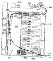
도 2b 는 전방 도어가 열린 위치에 있는 캐비넷을 갖는 도 2a 의 섬유 분배 허브의 전방 사시도.FIG. 2B is a front perspective view of the fiber dispensing hub of FIG. 2A with the cabinet in a front door open position;
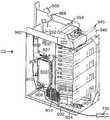
도 2c 는 스윙 프레임이 캐비넷 밖으로 돌아 나온 도 2a 의 섬유 분배 허브의 전방 사시도.FIG. 2C is a front perspective view of the fiber distribution hub of FIG. 2A with the swing frame back out of the cabinet. FIG.
도 3 은 도 2a 의 섬유 분배 허브의 케이블 경로 설계의 실시예를 나타내는 개략 흐름도.3 is a schematic flow diagram illustrating an embodiment of a cable path design of the fiber distribution hub of FIG. 2A;
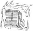
도 4 는 섬유 분배 허브로부터 고립된 도 2c 의 스윙 프레임의 전방 사시도.4 is a front perspective view of the swing frame of FIG. 2C isolated from the fiber distribution hub.
도 5 는 도 4 의 스윙 프레임의 전면도.5 is a front view of the swing frame of FIG.
도 6 은 도 4 의 스윙 프레임의 우측면도.6 is a right side view of the swing frame of FIG.
도 7 은 도 5 의 스윙 프레임의 상면도.7 is a top view of the swing frame of FIG.
도 8a 내지 도 8c 는 도 2a 의 분배 허브의 스플리터 모듈의 한 실시예를 나타내는 도.8A-8C illustrate one embodiment of a splitter module of the distribution hub of FIG. 2A.
도 9 는 저장 모듈에 고정되는 접속 단부를 포함하는 8 개의 출력 섬유를 갖는 스플리터 모듈의 예를 나타내는 도.9 shows an example of a splitter module with eight output fibers comprising a connecting end secured to the storage module.
도 10 은 스윙 프레임에 장착되는 스플리터 모듈로부터 스윙 프레임에 장착되는 저장 모듈로의 케이블/섬유 경로의 한 예를 나타내는 도.10 illustrates an example of a cable / fiber path from a splitter module mounted to a swing frame to a storage module mounted to a swing frame.
도 11 은 스윙 프레임에 장착되는 스플리터 모듈로부터 스윙 프레임에 장착되는 단말 모듈로의 케이블/섬유 경로의 한 예를 나타내는 도.FIG. 11 illustrates an example of a cable / fiber path from a splitter module mounted on a swing frame to a terminal module mounted on a swing frame. FIG.
도 12a 및 도 12b 는 도 2a 의 분배 허브의 단말 모듈의 한 예의 전방 및 후방 사시도.12A and 12B are front and rear perspective views of an example of a terminal module of the distribution hub of FIG. 2A.
도 13 은 도 4 의 스윙 프레임의 후방 사시도.FIG. 13 is a rear perspective view of the swing frame of FIG. 4. FIG.
도 14 는 도 4 의 스윙 프레임의 또 다른 사시도.14 is another perspective view of the swing frame of FIG.
도 15 는 도 4 의 스윙 프레임의 좌측면도.FIG. 15 is a left side view of the swing frame of FIG. 4; FIG.
도 16 은 스윙 프레임의 후방 측에 장착되는 인터페이스 장치 및 케이블 관리 장치의 예를 포함하는 스윙 프레임의 배면도.FIG. 16 is a rear view of a swing frame including examples of an interface device and a cable management device mounted on the rear side of the swing frame.
도 17 은 스윙 프레임 상의 인터페이스 장치 및 케이블 관리 장치의 구성의 한 예를 나타내는 후방 사시도.17 is a rear perspective view showing an example of the configuration of an interface device and a cable management device on a swing frame;
도 18 은 인터페이스 장치 및 케이블 관리 장치의 구성의 다른 예를 나타내는 후방 사시도.18 is a rear perspective view illustrating another example of the configuration of the interface device and the cable management device.
도 19 는 인터페이스 장치 및 케이블 관리 장치의 구성의 또 다른 예를 나타 내는 후방 사시도.19 is a rear perspective view illustrating another example of the configuration of the interface device and the cable management device.
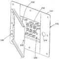
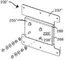
도 20 은 케이블 접지 인터페이스를 수용하기 위한 부 칸막이 또는 포켓을 갖는 섬유 분배 허브 캐비넷의 배면도.FIG. 20 is a rear view of a fiber distribution hub cabinet having a secondary divider or pocket for receiving a cable ground interface. FIG.
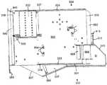
도 21 은 도 20 의 섬유 분배 허브에 있어서 캐비넷이 개방되고 스윙 프레임이 회전되어 나와 있어, 상기 접지 인터페이스의 접지 핀이 상기 캐비넷의 주 칸막이의 내부로 돌출되어 있는 것을 나타내는 전면도.FIG. 21 is a front view of the fiber distribution hub of FIG. 20 showing that the cabinet is opened and the swing frame is rotated so that the ground pin of the ground interface protrudes into the main partition of the cabinet; FIG.
도 22 는 섬유 분배 허브의 주 캐비넷으로부터 분리된 도 20 의 부 칸막이의 사시도.22 is a perspective view of the secondary divider of FIG. 20 separated from the main cabinet of the fiber distribution hub.
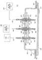
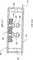
도 23 은 도 20 의 절단선 23-23 에 따른 단면도.FIG. 23 is a cross sectional view along cut line 23-23 in FIG. 20;
도 24 는 원격 통신 캐비넷의 후측으로부터 접근될 수 있는 대안적인 부 칸막이의 일 측을 나타내는 도.FIG. 24 shows one side of an alternative subdivision that can be accessed from the back side of the telecommunication cabinet;
도 25 는 도 24 의 대안적인 부칸막이의 반대 측을 나타내는 도.FIG. 25 shows the opposite side of the alternative subdivision of FIG. 24.
도 26 은 도 24 의 부 칸막이의 상면도.FIG. 26 is a top view of the secondary partition of FIG. 24. FIG.
도 27 은 도 26 의 절단선 27-27 에 따른 단면도.FIG. 27 is a cross sectional view along cut line 27-27 in FIG. 26;
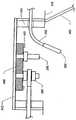
도 28 은 접지선이 부 칸막이 내로 연장하여 부 칸막이 내의 접지 기둥에 결합된 도 27 의 단면도.FIG. 28 is a cross sectional view of FIG. 27 with the ground wire extending into the secondary partition and joined to a ground column in the secondary partition;
도 29 는 접지선 중 하나가 접지 기둥 중 하나로부터 떨어져 있는 도 28 의 단면도.FIG. 29 is a cross sectional view of FIG. 28 with one of the ground wires away from one of the ground pillars.
도 30 은 대안적인 스윙 프레임의 사시도.30 is a perspective view of an alternative swing frame.
도 31 은 스윙 프레임이 회전되어 나와 있는 또 다른 섬유 분배 허브 (FDH) 의 사시도.31 is a perspective view of another fiber dispensing hub (FDH) with the swing frame rotated out;
도 32 는 상기 FDH 의 내부가 보이도록 상부 패널 및 스윙 프레임이 제거되어 있는 도 31 의 FDH 의 전방 사시도.FIG. 32 is a front perspective view of the FDH of FIG. 31 with the top panel and swing frame removed so that the inside of the FDH is visible.
도 33 은 스윙 프레임이 제거된 도 31 의 FDH 의 전방 분해 사시도.33 is an exploded front perspective view of the FDH of FIG. 31 with the swing frame removed.
도 34 는 하나의 단말 모듈 및 프레임 부재가 스윙 프레임으로부터 분해되어 있는 도 31 의 FDH 의 전방 사시도.FIG. 34 is a front perspective view of the FDH of FIG. 31 with one terminal module and frame member disassembled from the swing frame;
도 2 내지 도 7 을 참조하면, 본 발명의 원리에 따른 섬유 분배 허브 (FDH, Fiber Distribution Hub) (200) 의 예가 나타나 있다. FDH (200) 는 내부 구성 요소를 수용하는 캐비넷 (201) 을 포함한다. 캐비넷 (201) 은 공급자 케이블 (또는 예컨대 F1 케이블) (700) 및 가입자 케이블 (708) 이 캐비넷 (201) 을 출입하는 개구를 포함한다 (도 2c 참조). 스윙 프레임 (300) 이 캐비넷 (201) 내부의 힌지 (355) 에 피벗 가능하도록 장착된다. 스윙 프레임 (300) 은 스윙 프레임 (300) 을 전방부 (302) (도 4 참조) 및 후방부 (304) (도 2c 참조) 로 분할하는 격벽 (301) 을 포함한다. 격벽 (301) 은 단말 영역 (311) 및 저장 영역 (313) 을 갖는 주 패널 (310) 을 포함한다. 일반적으로, 하나 이상의 단말 모듈 (400) (도 13a 및 도 13b 참조) 이 단말 영역 (311) 에 구비되어 있고, 하나 이상의 저장 모듈 (600) (도 9 참조) 이 저장 영역 (313) 에 구비되어 있다. 몇몇 실시형태에서, 격벽 (301) 은 또한 주 패널 (310) 에 인접해 위치하고 케이블 관리를 위해 구성된 부 패널 (315) 을 포함한다. 스윙 프레임 (300) 의 후방부 내 에는 하나 이상의 공급자 케이블 인터페이스 (800) 가 위치할 수 있다. 스윙 프레임 (300) 의 상부에는 하나 이상의 스플리터 모듈 (500) 을 수용하는 스플리터 모듈 하우징 (322) 이 하나 이상 위치한다.2-7, an example of a fiber distribution hub (FDH) 200 in accordance with the principles of the present invention is shown. The
도 3 은 FDH (200) 용 케이블 경로의 한 예를 나타내는 개략 흐름도이다. FDH (200) 는 일반적으로 외부 플랜트 (Outside Plant,OSP) 환경에서 유입 섬유와 유출 섬유 사이의 단말 패널에서의 연결을 관리한다. 여기서는 섬유들 간의 "연결 (connection)" 은 직간접적 연결을 모두 포함하는 용어로 사용된다. 유입 섬유의 예로서는 캐비넷으로 유입하는 공급자 케이블 섬유 및 이 공급자 케이블 섬유를 단말 패널과 연결하는 중간 섬유 (예컨대 스플리터로부터 연장하는 접속 피그테일 및 패칭 섬유/점퍼) 를 포함한다. 유출 섬유의 예로서는, 캐비넷에서 나가는 가입자 케이블 섬유 및 이 가입자 케이블 섬유를 단말 패널과 연결하는 임의의 중간 섬유를 포함한다. FDH (200) 는 작업중의 접근 및 재구성이 필요한 네트워크 위치에 광 전송 신호를 위한 상호 접속 인터페이스를 제공한다. 예를 들면, 상기 지적한 바와 같이, FDH (200) 는 공급자 케이블을 분할하고 분할된 공급자 케이블을 가입자 위치로 보내지는 분배 케이블과 연결한다. 또한, FDH (200) 는 일정 범위의 다른 크기 및 섬유 개수를 수용하고 피그테일, 팬아웃 및 스플리터의 공장 설비를 유지하도록 설계된다.3 is a schematic flowchart illustrating an example of a cable path for an
도 3 에 나타난 바와 같이, 공급자 케이블 (700) 은 최초로 캐비넷 (201) 을 통과하여 (예컨대 도 2c 에 나타나 있는 바와 같이 통상적으로는 캐비넷 (201) 의 뒤쪽 또는 바닥을 통과하여) FDH (200) 내로 들어간다. 어떤 실시형태에서는, 공급자 케이블 (700) 의 섬유는 리본 섬유를 포함할 수 있다. 공급자 케이블 (700) 의 예로서는 서비스 제공자 중앙국 (101) 에 연결된 12 개 내지 48 개의 개별 섬유를 포함할 수 있다. 몇몇 실시형태에서는, 캐비넷 (201) 에 들어간 후, 공급자 케이블 (700) 의 섬유는 공급자 케이블 인터페이스 (800) (예컨대 섬유 광 어댑터 모듈, 접합 트레이 (splice tray) 등) 로 이어진다. 공급자 케이블 인터페이스 (800) 에서는, 공급자 케이블 (700) 의 하나 이상의 섬유는 개별 스플리터 입력 섬유 (702) 에 각각 연결된다. 스플리터 입력 섬유 (702) 는 공급자 케이블 인터페이스 (800) 로부터 스플리터 모듈 하우징 (322) 으로 이어진다. 스플리터 모듈 하우징 (322) 에서, 스플리터 입력 섬유 (702) 는 개별 스플리터 모듈 (500) 에 연결되고, 여기서 스플리터 입력 섬유 (702) 는 접속 단부를 갖는 다중 피그테일 (704) 로 각각 분할된다. 하지만 다른 실시형태에서는, 공급자 케이블 (700) 의 섬유는 접속화되어 스플리터 모듈 (500) 로 직접 이어지고, 이에 의해 중간적인 공급자 케이블 인터페이스 (800) 의 필요성을 회피 또는 제거하게 된다.As shown in FIG. 3, the
피그테일 (704) 이 사용중이지 않은 경우, 접속 단부 (706) 는 스윙 프레임 (300) 의 저장 영역 (313) 에 장착된 저장 모듈 (600) 에 일시적으로 저장될 수 있다. 피그테일 (704) 이 사용을 위해 필요해지는 경우, 피그테일 (704) 은 스플리터 모듈 (500) 로부터 스윙 프레임 (300) 의 단말 영역 (311) 에 구비된 단말 모듈 (400) 로 이어진다. 단말 모듈 (400) 에서, 피그테일 (704) 은 분배 케이블 (708) 의 섬유에 접속된다. 단말 패널은 유입 패널과 유출 패널 사이의 분할 선이다. 통상적인 분배 케이블 (708) 은 네트워크 의 F2 부분을 형성하고 (도 1 참조) 통상적으로 FDH (200) 으로부터 가입자 위치 (709) 로 이어지는 복수개의 섬유 (예컨대 144, 216 또는 432 개의 섬유) 를 포함한다.If the
몇몇 실시형태에서, 공급자 케이블 (700) 의 하나 이상의 섬유는 어떤 스플리터 모듈 (500) 에도 접속되어 있지 않다. 대신에, 이러한 공급자 케이블 (700) 의 섬유들은 접속 단부 (714) 를 갖는 관통 섬유 (712) 에 접속되어 있다. 관통 섬유 (712) 는 스플리터 모듈 (500) 에 먼저 접속되지 않고, 단말 모듈 (400) 에 접속되어 있다. 섬유 (712) 를 분할하지 않음으로써, 보다 강한 신호를 가입자에게 전송할 수 있다. 관통 섬유 (712) 의 접속 단부 (714) 는 사용중이지 않은 경우 저장 영역 (313) 에 저장될 수 있다.In some embodiments, one or more fibers of
다시 도 2a 내지 도 2c 를 참조하면, FDH (200) 의 캐비넷 (201) 은 상부 패널 (202), 바닥 패널 (203), 우측 패널 (204), 좌측 패널 (206), 후방 패널 (205) 및 하나 이상의 전방 도어를 포함한다. 몇몇 실시형태에서, 상기 하나 이상의 전방 도어는 우측 도어 (210) 및 좌측 도어 (212) 를 포함한다. 한 실시형태에서, 전방 도어 (210, 212) 는 락 (lock) (211) 을 포함한다. 하나 이상의 전방 도어는 캐비넷 (201) 내에 장착된 요소에 접근이 용이하도록 하기 위해 힌지 (214, 216) 를 사용하여 캐비넷 (201) 에 피벗가능하게 장착된다.Referring again to FIGS. 2A-2C, the
일반적으로 FDH (200) 의 캐비넷 (201) 은 비, 바람, 먼지, 설치류 및 다른 오염물질에 대해 내부 요소들을 보호하도록 구성되어 있다. 하지만, 캐비넷 (201) 은 용이한 설치를 위하여 비교적 가벼운 중량을 유지하며, 장치 내의 습기 축적을 방지하기 위하여 통기성을 유지한다. 몇몇 실시형태에서는, 내부식성을 위해 중분말 피복 마감 (heavy powder coat finish) 된 알루미늄 구성이 제공된다. 한 실시형태에서, 캐비넷 (201) 은 중 게이지 알루미늄으로부터 제조되고 NEMA-4X 등급을 갖는다. 하지만 다른 실시형태에서, 다른 재료가 사용될 수도 있다.In general,
예로 든 실시형태에 따르면, FDH (200) 는 주상 마운트 (pole mount) 또는 주각 마운트 (pedestal mount) 내에 구비된다. 예를 들면, 도 2 에 나타낸 바와 같이, 원하는 위치에 캐비넷 (201) 을 용이하게 배치하기 위해 캐비넷 (201) 상에는 루프 (218) 가 구비될 수 있다. 루프 (218) 는 크레인을 사용하여 캐비넷을 위치시키는 데 사용될 수 있다. 특히, 크레인은 캐비넷 (201) 을 지하 영역으로 내려보낼 수 있다. 몇몇 실시형태에서, 루프 (218) 는 제거 가능하거나, 상부 캐비넷 패널 (202) 로부터 돌출하지 않도록 조정될 수 있다.According to an exemplary embodiment, the
또한 도 2b ~ 2c 를 참조하면, FDH (200) 의 스윙 프레임 (300) 은 상부 패널 (320), 바닥 패널 (330), 우측 패널 (340) 및 좌측 패널 (341) 을 포함한다. 스윙 프레임 (300) 의 좌측 (341) 에는 힌지 장착 스트립 (350) 이 위치한다. 도 4 에 나타낸 바와 같이, 격벽 (301) 은 주 패널 (310) 을 힌지 장착 스트립 (350) 에 접속하는 접속 패널 (319) 을 추가로 포함한다. 도 4 에 가장 잘 나타난 바와 같이, 부 패널 (315) 의 일부분 (325) 은 스윙 프레임 (300) 의 상부 패널 (320) 을 지나 상방으로 연장한다. 격벽 (301) 은 상부 패널 (320) 과 바닥 패널 (330) 사이에서 수직으로 연장하며, 우측 패널 (340) 과 좌측 패널 (341) 사이에서 측방향으로 연장한다.Referring also to FIGS. 2B-2C, the
몇몇 실시형태에서, 스윙 프레임 (300) 의 힌지 장착 스트립 (350) 은 하나 이상의 힌지 (355) 를 사용하여 FDH (200) 의 캐비넷 (201) 에 장착된다. 힌지 (355) 는, 세척, 테스트, 수리, 추가 등을 위하여 스윙 프레임 (300) 의 후방부 (304) 에 있는 광학 요소에 접근할 수 있도록, 단말 모듈 (400), 저장 모듈 (600), 공급자 케이블 인터페이스 (800) 및 스플리터 모듈 (500) 을 포함하는 스윙 프레임 (300) 전체가 캐비넷 (201) 의 전방 도어 (210) 밖으로 돌아나올 수 있도록 한다. 스윙 프레임 (300) 을 캐비넷 (201) 밖으로 회전시킴으로써 스윙 프레임 (300) 의 우측 패널 (340) 이 캐비넷 (201) 의 내부 공간으로부터 멀어지게 된다. 몇몇 예로 든 실시형태에서, 스윙 프레임 (300) 은 캐비넷 (201) 밖으로 90 도 이상 회전되어 나올 수 있다.In some embodiments, the
몇몇 실시형태에서, 스윙 프레임 (300) 의 힌지 (355) 는 스윙 프레임 (300) 으로 이어지는 섬유 케이블을 위한 단일 굽힘 지점을 제공하도록 위치되어 있다. 이 힌지 점은 섬유 굽힘을 제어하도록 구성되어 있다. 특히, 여기서 매우 상세하게 논의될 힌지 (355) 및 케이블 관리 장치는, 스윙 프레임 (300) 이 개방 또는 폐쇄되어 있는 경우 제조 권장 굴곡 반경이 유지될 수 있도록 설계된다. 한 실시형태에서, 캐비넷 (201) 은 공장, 플랜트에서, 케이블 다발이 힌지 (355) 주위에 정돈되도록 구성될 수 있다. 캐비넷 (201) 의 사전 구성은 케이블 설치가 부정확하게 이루어질 가능성을 줄여준다.In some embodiments, the
도 2c 에 나타난 바와 같이, 스윙 프레임 (300) 이 개방 위치에 있는 경우, 스윙 프레임 (300) 의 후방부 (304) 의 요소들에 접근이 가능하다. 예를 들면, 주 패널 (310) 의 후방 측 및 부 패널 (315) 의 후방 측에 접근이 가능하다. 또한, 스플리터 모듈 하우징 (322) 내에 위치한 스플리터 모듈 (500) (도 4 참조) 은 스플리터 모듈 (500) 이 캐비넷 (201) 밖으로 돌아 나오는 경우 스윙 프레임 (300) 의 개방 상부를 통하여 접근 가능하다. 반대로, 스윙 프레임 (300) 이 폐쇄 위치에 있는 경우에는 (도 2b 참조), 스윙 프레임 (300) 의 전방부 (302) 의 요소들만이 쉽게 접근 가능하다.As shown in FIG. 2C, when the
예로 든 실시형태에서, 스윙 프레임 (300) 은 래치가 작동될 때까지 FDH (200) 의 캐비넷 (201) 내에 스윙 프레임 (300) 을 폐쇄 위치에 잠그게 되는 해제 래치를 포함한다. 일단 래치가 작동되면, 스윙 프레임 (300) 은 캐비넷 (201) 밖으로 돌아나올 수 있다. 또한, 회전 잠금 부재 (도시 생략) 는 개방 위치에서 스윙 프레임 (300) 을 고정하기 위해 스윙 프레임 (300) 의 후방부 (304) 에 장착될 수 있다.In the exemplary embodiment, the
도 4 내지 도 5 를 참조하면, 스윙 프레임 (300) 의 저장 영역 (313) 은 단말 영역 (311) 아래쪽에 위치한다. 하지만 다른 실시형태에서는, 저장 영역 (313) 은 단말 영역 (311) 의 상부 또는 단말 영역과 인접할 수도 있다. 일반적으로, 단말 영역 (311) 은 어댑터 (450) 가 단말 모듈 (400) 로부터 통과해 연장하는 (도 13a~13b 참조) 하나 이상의 직사각형 개구 (312) 를 한정한다. 단말 모듈 (400) 은 여기서 보다 상세히 설명된다. 도 4 에 나타난 실시형태에서, 단말 영역 (311) 은 각 열이 12 개의 기다란 슬롯을 포함하는 두 개의 직사각형 개구 (312) 열을 포함한다. 스트립 (309) 은 각 열의 직사각형 개구 (312) 를 분 리하고 라벨 정보 (예컨대 커넥터 명칭) 를 붙이기 위한 표면 영역을 제공한다. 저장 영역 (313) 은 또한 저장 모듈 (600) (도 9 참조) 이 장착되는 개구 (314) 를 하나 이상 한정한다. 저장 모듈 (600) 은 여기서 보다 상세히 설명된다.4 to 5, the
격벽 (301) 은 바닥 패널 (330) 을 전방부 (331) (도 4 참조) 및 후방부 (336) (도 2c 및 도 14 참조) 로 두갈래로 나뉜다. 일반적으로, 바닥 패널 (330) 의 전방부 (331) 는 격벽 (301) 으로부터 전방으로 돌출된다. 몇몇 실시형태에서, 전방부 (331) 는 제 1 전방부 (332) 및 제 2 전방부 (334) 로 더욱 분할된다. 각 전방부 (332, 334) 는 바닥 패널 (330) 과 실질적으로 직각으로 돌출되는 플랜지 (333, 335) 를 포함한다. 바닥 패널 (330) 의 전방부 (331) 는 이에 의해 저장 영역 (313) 또는 부 패널 (315) 로부터 나온 슬랙 또는 초과 섬유를 보유하도록 구성되는 트로프를 형성한다. 제 1 전방부 (332) 의 가장자리 (337) 는 스윙 프레임 (300) 이 트로프로부터 방해받지 않고 회전하여 개방될 수 있도록 기울어져 있다.The
도 4 및 도 6 에 가장 잘 나타나 있는 바와 같이, 격벽은 측 패널 (340) 을 전방 플랜지 (342) 및 후방 플랜지 (344) 로 각각 분할한다. 전방 플랜지 (342) 는 부 패널 (315) 로부터 전방으로 연장하며, 후방 플랜지 (344) 는 부 패널 (315) 로부터 후방으로 연장한다. 후방 플랜지 (344) 는 바닥 패널 (330) 로부터, 상부 패널 (320) 로부터 연장하는 굴곡 리미터 (962) 쪽으로 연장한다. 전방 플랜지 (342) 는 바닥 패널 (330) 로부터 상부 패널 (320) 을 지나 부 패널 (315) 의 돌출 부분 (325) 으로 연장한다. 몇몇 실시형태에서, 전방 플랜지 (342) 는 후방 플랜지 (344) 와 실질적으로 평행한 전방 부분 (344), 및 부 패널 (315) 의 돌출 부분 (325) 과 전방 부분 (344) 사이에서 연장하는 경사 부분 (343) 을 포함한다.As best shown in FIGS. 4 and 6, the partition divides the
도 7 에 가장 잘 나타나 있는 바와 같이, 스윙 프레임 (300) 의 상부 패널 (320) 은 실질적으로 직사각형이다. 상부 패널 (320) 은 앞쪽 가장자리 (326) 및 뒤쪽 가장자리 (327) 를 포함한다. 플랜지 (323, 324) (도 4 참조) 는 가장자리 (326, 327) 로부터 각각 상방으로 돌출되어 있다. 상부 패널 (320) 은 또한 좌측 (341) 부근의 제 1 단부 (328) 및 우측 패널 (340) 부근의 반대편 단부 (329) 를 갖는다. 굴곡 반경 리미터 (940) 는 제 1 단부 (328) 로부터 상방으로 연장한다. 몇몇 실시형태에서, 상부 패널 (320) 의 단부 (329) 의 일부분은 우측 패널 (340) 의 전방 플랜지 (342) 와 함께 채널 (B) 의 폭을 한정한다. 채널 (B) 을 한정하는 단부 (329) 의 상기 부분은 단부 (329) 의 잔여 부분에 도달하기 전에 끝난다. 채널 (B) 의 깊이는 부 패널 (315) 로부터 바닥 패널 (330) 의 제 2 전방부 (33) 의 플랜지 (335) 까지 연장한다.As best seen in FIG. 7, the
FDH (200) 의 스플리터 모듈 하우징 (322) 은 제 1 단부 (328) 부근의 상부 패널 (320) 상에 위치한다. 스플리터 모듈 하우징 (322) 은 FDH (200) 의 스플리터 모듈 (500) 을 보호, 조직 및 고정하는 역할을 한다. 스플리터 모듈 하우징 (322) 은 다양한 수의 스플리터 모듈 (500) 을 수용하기 위해 다양한 크기로 구성될 수 있다. 스플리터 모듈 하우징 (322) 은 일반적으로 직사각형이며, 하나 이상의 스플리터 모듈 (500) 을 수용하기 위한 크기의 개방된 내부에 하나 이상의 위치를 한정한다. 스플리터 모듈 (500) 을 수용하기 위하여, 모듈 하우징 (322) 은 스플리터 모듈 (500) 을 지지/고정하기 위한 구조를 포함한다. 예로 든 실시형태에서, 스플리터 모듈 (500) 은 스플리터 모듈 하우징 (322) 내에 스냅 결합하도록 설계되어 있다. 한 실시형태에서, 스플리터 모듈 (500) 은 스플리터 모듈 하우징 (322) 내에 전방으로부터 후방으로 (즉, 단부 (329) 를 향하는 측으로부터 단부 (328) 를 향하는 측으로) 수용되어 있다. 모듈 하우징 (322) 은 또한 스플리터 모듈 (500) 이, 도 3 의 섬유 (702) 와 같이, 스플리터 모듈 (500) 의 일 단부 상에 입력 섬유를 수용할 수 있도록, 또한 스플리터 모듈 (500) 의 반대편 단부로부터, 도 3 의 피그테일 (704) 과 같이, 다수의 섬유를 출력할 수 있도록 구성되어 있다.The
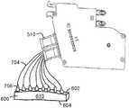
이제 도 8a ~ 8c 를 참조하면, 스플리터 모듈 하우징 (322) 내에 장착될 수 있는 스플리터 모듈 (500) 의 한 유형은 일체화 커넥터를 갖는 스플리터이다. 도 8a 는 그러한 스플리터 모듈 (500) 의 좌측도이다. 스플리터 모듈 (500) 은 전방으로 돌출되어 있는 하나 이상의 보호 부트 (boot) (510) 및 후방으로 돌출되어 있는 하나 이상의 일체화 커넥터 (520) 를 갖는 하우징 (505) 을 포함한다. 도시된 실시형태에서, 두 개의 부트 (510) 는 전방으로부터 돌출되고, 두 개의 일체화 커넥터 (520) 는 스플리터 하우징 (505) 으로부터 후방으로 돌출된다. 한 예로 든 실시형태에서 (도시 생략), 각 스플리터는 4 개의 일체화 커넥터 (520) 를 갖는다. 몇몇 실시형태에서, 핸들 (540) 또한 스플리터 하우징 (505) 의 전방 단부로부터 돌출되어 있다. 도 8b 는 스플리터 모듈 (500) 의 일체화 요소를 나타내는 도 8a 의 스플리터 모듈 (500) 의 분해도이다.Referring now to FIGS. 8A-8C, one type of
도 8c 는 스플리터 모듈 하우징 (322) 내에 삽입된 도 7a 의 스플리터 모듈 (500) 의 단면도를 나타낸다. 어댑터 어셈블리 (530) 는 고정구 (536) 를 사용하여 스플리터 모듈 하우징 (322) 에 고정된다. 한 실시형태에서, 어댑터 어셈블리 (530) 는 스플리터 모듈 하우징 (322) 의 후방 측에 장착된다. 어댑터 어셈블리 (530) 는 스플리터 모듈 (500) 이 스플리터 모듈 하우징 (322) 내에 삽입될 때 스플리터 모듈 (500) 의 일체화 커넥터 (520) 를 수용하도록 구성된다. 도시된 바와 같이, 어댑터 어셈블리 (530) 는 추가로 공급자 케이블 (700) 과 관련된 반대편 커넥터를 수용하도록 구성된다. 몇몇 실시형태에서, 어댑터 어셈블리 (530) 는 스플리터 입력 섬유 (702) 를 종결시키는 커넥터 (703) 를 수용한다. 다른 실시형태에서, 어댑터 어셈블리 (530) 는 공급자 케이블 (700) 자체를 종결시키는 커넥터 (701) 를 수용한다. 이러한 방식으로, 공급자 케이블 (700) 은 스플리터 모듈 (500) 에 쉽게 연결될 수 있다.8C shows a cross-sectional view of the
스플리터 모듈 (500) 의 다른 실시형태는 일체화 커넥터 (520) 를 포함하지 않는다. 그러한 실시형태에서, 어댑터 어셈블리 (530) 은 스플리터 모듈 하우징 (322) 에 장착되어 있지 않고 공급자 케이블 (700) 은 스플리터 모듈 (500) 내로 직접 접속될 수 없다. 대신에, 입력 피그테일 (도시 생략) 은 스플리터 하우징 (505) 을 통과하여 스플리터 모듈 (500) 에 들어간다. 입력 피그테일의 반대편 단부는 커넥터화되어 있을 수도 있고 커넥터화되어 있지 않을 수도 있다. 단부 (701) 가 커넥터 (도시 생략) 에서 종결되는 경우, 입력 섬유 (702) 는 어 댑터 모듈 (801) (도 18 참조) 을 사용하여 공급자 케이블 (700) 과 연계된다. 단부 (701) 가 커넥터화되어 있지 않은 경우에는, 입력 섬유 (702) 는 접합 트레이 (808) (도 19 참조) 를 사용하여 공급자 케이블 (700) 과 접합된다.Another embodiment of the
통상적으로, 각 스플리터 모듈 (500) 은 1 ~ 4 개의 섬유를 수용하며, 각 입력 섬유에 대해 2 ~ 16 개의 섬유 (704) 를 출력한다. 한 예로 든 실시형태에서, 4 개의 입력 섬유 (702) 가 스플리터 모듈 (500) 에 들어가고, 32 개의 피그테일 섬유 (704) 가 스플리터 모듈 (500) 을 나온다. 스플리터 모듈 (500) 에 관한 추가 정보는, 발명의 명칭이 "광섬유 스플리터 모듈"인 대리인 정리 번호 (attorney docket number) 2316.2314US01 인 미국 특허출원에서 찾을 수 있으며, 이를 참조하기로 한다. 다른 유형의 스플리터 모듈에 대한 추가 정보는 2004년 11월 3일자 미국 특허출원 제 10/980,978 호인 "광섬유 모듈 및 후방 커넥터를 포함하는 시스템", 2005 년 5월 25일자 미국 특허출원 제 11/138,063 호인 "광섬유 스플리터 모듈", 2005년 8월 29일자 미국 특허출원 제 11/215,837 호인 "커넥터 접속을 갖는 광섬유 스플리터 모듈", 및 2005년 12월 28일자 미국 특허출원 제 11/321,696 호인 "섬유 분배 허브용 스플리터 모듈" 에서 찾을 수 있으며, 이를 참조하기로 한다.Typically, each
이제 도 9 ~ 10 을 참조하면, 스플리터 모듈 (500) 및 저장 모듈 (600) 은 스윙 프레임 (300) 에 증가적으로 추가된다. 도 9 는 스플리터 모듈 (500) 상의 보호 부트 (510) 로부터 빠져나오는 다수의 커넥터화된 피그테일 (704) 을 갖는 스플리터 모듈 (500) 을 나타낸다. 커넥터화된 피그테일 (704) 은 통상적으로 스윙 프레임 (300) 상에 설치되기 전에 하나 이상의 저장 모듈 (600) 내에 저장된다. 몇몇 실시형태에서, 각 피그테일 (704) 의 커넥터 (706) 은 스플리터 모듈 (500) 이 공장을 떠나기 전에 저장 모듈 (600) 내에 고정된다. 통상적으로, 각 스플리터 모듈 (500) 의 커넥터화된 피그테일 (704) 은 각각 8 개의 커넥터를 유지하는 4 개의 저장 모듈 (600) 로 이어진다.Referring now to FIGS. 9-10,
저장 모듈 (600) 은 전방 측 (602) 및 후방 측 (604) 을 갖는 본체 (610) 를 포함한다. 본체 (610) 는 하나 이상의 섬유 커넥터 (706) 를 유지하도록 구성되어 있다. 통상적으로, 본체 (610) 는 약 8 개의 커넥터 (706) 를 유지하도록 구성되어 있다. 몇몇 실시형태에서, 본체 (610) 는 단일 열 구성 내에 섬유 커넥터 (706) 를 보유하도록 배열되어 있다. 다른 실시형태에서, 본체 (610) 는 정방형 패턴 또는 임의의 다른 원하는 구성으로 된 커넥터 (706) 를 유지하도록 배열될 수 있다. 저장 모듈 (600) 에 관한 추가 정보는 2003년 6월 30일자 미국 특허출원 10/610,325 호인 "광섬유 커넥터 홀터 및 방법", 2003년 7월 2일자 미국 특허출원 10/613,764 호인 "원격 통신 접속 캐비넷", 및 2004년 6월 18일자 미국 특허출원 10/871,555 호인 "다중 위치 광섬유 커넥터 홀더 및 방법" 에서 찾을 수 있으며, 이를 참조하기로 한다.
몇몇 실시형태에서, 본체 (610) 는 주 패널 (310) 의 저장 영역 (313) 내에 한정된 개구 (314) 중 하나에 스냅 결합하도록 설계되어 있다. 개구 (314) 는 주 패널 (310) 의 저장 영역 (313) 내에 임의의 원하는 구성으로 배열될 수 있다. 도 10 에 도시된 예에서, 주 패널 (310) 의 저장 영역 (313) 은 직사각형 패턴 으로 9 개의 개구 (314) 를 한정한다. 각 개구 (314) 는 8 개의 접속 단부 (706) 를 일렬로 보유하도록 배열된 저장 모듈 본체 (610) 를 수용하도록 구성되어 있다.In some embodiments, the
도 10 에 도시된 바와 같이, 스플리터 모듈 (500) 이 설치 동안 스플리터 모듈 하우징 (322) 내에 수용될 때, 이에 대응하는 저장 모듈 (600) 이 주 패널 (310) 의 저장 영역 (313) 상에 수용된다. 보기에 용이하도록, 하나의 피그테일 (704) 및 하나의 저장 모듈 (600) 을 갖는 단 하나의 스플리터 (500) 만이 도시되었다. 스플리터 모듈 (500) 로부터 저장 모듈 (600) 로 연장하는 피그테일 (704) 은 보호 부트 (510) 로부터 상부 패널 (320) 을 가로질러 부 패널 (315) 의 전방 측상의 채널 (B) 을 통과해 내려가고 스윙 프레임 (300) 의 바닥 패널 (330) 을 가로지르게 된다.As shown in FIG. 10, when the
이러한 경로를 달성하기 위해, 상부 패널 (320) 및 부 패널 (315) 은 케이블 관리 장치를 포함한다. 몇몇 실시형태에서, 상부 패널 (320) 상의 케이블 관리 장치는 스플리터 하우징 (322) 과 굴곡 반경 리미터 (962) 사이에 위치한 제 1 스풀 (952), 및 굴곡 리미터 (940) 와 전방 플랜지 (342) 사이의 위치한 제 2 스풀 (954) 을 포함한다. 스플리터 모듈 (500) 로부터 나온 피그테일 (704) 은 제 1 스풀 (952) 주위에 우선 감긴 후 제 2 스풀 (954) 주위에 감긴다.To accomplish this route, the
탭 (965) 을 갖고 상부 패널 (320) 로부터 하방으로 연장하는 굴곡 반경 리미터 (964) 는 채널 (B) 을 부분적으로 한정한다. 제 2 스풀 (954) 로부터 피그테일 (704) 의 일부가 굴곡 반경 리미터 (964) 를 지나 채널 (B) 내로 이어진다. 몇몇 실시형태에서, 부분 섬유 스풀 (966) 은 부 패널 (315) 의 돌출 부분 (325) 으로부터 연장하도록 장착되어 있고 또한 섬유가 채널 (B) 내로 이어지도록 향하고 있다. 섬유 (704) 의 과도한 중량 및 얽힘을 피하기 위해, 몇몇 섬유 (704) 는 굴곡 리미터 (964) 대신에 부분적인 스풀 (966) 을 지나 채널 (B) 내로 이어질 수 있다. 피그테일 (704) 이 굴곡 리미터 (964) 대신 스풀 (966) 위로 이어지도록 함으로써 여분의 슬랙이 처리될 수 있다. 굴곡 리미터 (968) 는 또한 부 패널 (315) 의 돌출 부분 (325) 상에 장착되어 섬유가 부분 스풀 (966) 로 이어지도록 향할 수 있다.A
부 패널 (315) 의 전방은 하나 이상의 부분 스풀 (970) 열 및 하나 이상의 반경 리미터 (980) 열을 포함한다. 한 예로 든 실시형태에서, 부분 스풀 (970) 은 채널 (B) 아래로 이어진 섬유가 부분 스풀 (970) 주위로 적어도 부분적으로 감길 수 있도록 향하고 있다. 섬유는 부분 스풀 (970) 로부터 바닥 패널 (330) 을 따라 저장 모듈 (600) 로 전해지거나, 반경 리미터 (980) 를 지나 단말 모듈 (400) 로 전해질 수 있다. 리미터 (980) 는 부분 스풀 (970) 로부터 이어진 섬유가 과도한 굴곡 없이 단말 모듈 (400) 로 전해질 수 있도록 향하고 있다.The front of the
이제 도 11 을 참조하면, 저장 모듈 (600) 내에 보유된 피그테일 (704) 이 가입자 분배 케이블 (708) 에 연결되어야 하는 경우, 이에 대응하는 커넥터 (706) 는 저장 모듈 (600) 로부터 제거되고, 단말 모듈 (400) 상의 적절한 어댑터 (450) 로 전달된다. 이러한 전달 과정 동안, 섬유는 어댑터 (450) 에 도달하기 위해 부분 스풀 (972) 과 같이 서로 다른 부분 스풀 (970) 주위로 다시 감길 필요가 있 다. 어댑터 (450) 에 도달하기 전 과도한 굴곡을 피하기 위해 섬유는 부분 스풀 (972) 로부터 적합한 리미터 (980) 주위로 이어질 수 있다. 몇몇 실시형태에서, 섬유는 또한 어댑터 (450) 내로 접속하기 전에 주 패널 (310) 의 단말 영역 (311) 으로부터 연장하는 지지 핑거 (990) 를 통과하여 공급될 수 있다. 원래 저장 모듈 (600) 내에 고정된 모든 섬유 (704) 가 가입자 단말 모듈 (400) 로 이어진 경우, 새로운 스플리터 모듈 (500) 및 새로운 저장 모듈 (600) 을 위한 공간을 만들기 위해 비어 있는 저장 모듈 (600) 은 제거될 수 있다.Referring now to FIG. 11, when the
이제 도 12a ~ 12b 를 참조하면, 시간이 지나고 가입자 수가 증가함에 따라, 사용자는 단말 모듈 (400) 을 스윙 프레임 (300) 에 추가할 수 있다. 도 12a 및 도 12b 는 단말 모듈 (400) 의 한 예를 나타낸다. 단말 모듈 (400) 은 실질적으로 L-형상으로 구성되어 있는 단말 레그 (410) 및 관리 레그 (420) 를 포함한다. 몇몇 실시형태에서, 연결 영역 (430) 은 단말 레그 (410) 를 관리 레그 (420) 에 연결한다. 다른 실시형태에서, 연결 영역 (430) 은 단말 레그 (410) 또는 관리 레그 (420) 로 일체식으로 (monolithically) 형성된다. 또 다른 실시형태에서, 단말 레그 (410), 관리 레그 (420) 및 연결 영역 (430) 은 일체식으로 형성된다 (예를 들면 단일편의 굴곡 금속 시트로 구성되어 있다).Referring now to FIGS. 12A-12B, as time passes and the number of subscribers increases, the user may add the
몇몇 실시형태에서, 단말 모듈 (400) 의 단말 레그 (410) 의 전방 측 (도 12b에 도시) 은 주 패널 (310) 의 후방 측에 장착된다. 한 실시형태에서, 단말 레그 (410) 는 스크류 (417) 를 사용하여 주 패널 (310) 에 장착된다. 하지만, 다른 실시형태에서, 단말 모듈 (400) 을 주 패널 (310) 에 연결하기 위해 볼트, 리 벳, 못, 및 다른 장치들과 같은 다른 고정구들이 사용될 수 있다. 또 다른 실시형태에서, 단말 모듈 (400) 은 접착제를 사용하여 주 패널 (310) 에 부착될 수 있다.In some embodiments, the front side (shown in FIG. 12B) of the
각 단말 모듈 (400) 은 주 케이블 (700) 의 섬유를 분배 케이블 (708) 의 섬유에 연결하기 위한 하나 이상의 광섬유 어댑터 (450) 열을 포함한다. 각 어댑터 (450) 는 전방 단부 (452) 및 후방 단부 (454) 를 갖는다. 각 어댑터 (450) 의 전방 단부 (452) 는 주 라인 (700) 과 연계되는 섬유 (712) 의 커넥터 (714), 또는 주 라인 (700) 으로부터 분할된 섬유 (704) 의 커넥터 (706) 를 보유하도록 구성되어 있다. 각 어댑터 (450) 의 후방 단부 (454) 는 분배 케이블 (708) 의 섬유의 커넥터 (710) 를 보유하도록 구성되어 있다. 커넥터 (706) 가 주 패널 (310) 의 전방 측으로부터 어댑터 (450) 의 전방 단부 (452) 로 들어가고 분배 케이블 (708) 의 커넥터 (710) 가 주 패널 (310) 의 후방 측으로부터 어댑터 (450) 로 들어가도록, 어댑터 (450) 는 단말 레그 (410) 를 통과하여 돌출한다.Each
묘사된 실시형태에서, 각 모듈 (400) 은 어댑터의 두 개의 나란한 뱅크 (bank) 를 한정하도록 협력하는 6 개의 어댑터의 수평 열을 포함한다. 모듈 (400) 이 주 패널 (310) 에 장착되면, 레그 (410) 의 전방 측은 후측에 인접하며, 어댑터 (450) 열은 주 패널 (310) 에 의해 한정되는 해당 수평 슬롯 (314) 을 통과하여 전방으로 돌출한다.In the depicted embodiment, each
관리 레그 (420) 는 단말 레그 (410) 로부터 후방으로 연장한다. 관리 레그 (420) 는 모듈 (400) 상에 어댑터 (450) 를 수용하기 위해 적절한 수의 팬아 웃 (424) 을 포함한다. 예를 들면, 한 실시형태에서, 모듈 (400) 의 단말 레그 (410) 는 각 열이 12 개의 어댑터 (450) 를 갖는 6 개의 어댑터 (450) 열을 포함하고, 관리 레그 (420) 는 6 개의 12:1 팬아웃 (424) 을 포함한다. 여기서 12:1 팬아웃은 12 개의 광섬유를 수용하고 12 개의 섬유를 포함하는 단일 케이블 리본을 출력하도록 구성된 팬아웃을 의미하는 것으로 사용된다. 다른 실시형태에서는, 12:1 팬아웃 대신에 9 개의 8:1 팬아웃 또는 3 개의 24:1 팬아웃이 구비될 수도 있다. 또 다른 실시형태에서, 팬아웃은 섬유를 업재킷 (upjacket) 하는 데 사용될 수 있다.The
몇몇 실시형태에서, 단말 모듈 (400) 은 각 어댑터 (450) 에 결합된 커넥터화된 분배 케이블 (708) 을 포함하도록 공장에서 미리 케이블로 묶일 수 있다. 종결된 분배섬유 (708) 를 먼지, 티끌 및 다른 오염 물질로부터 보호하기 위해, 더스트캡 (453) 이 일반적으로 전방 단부 (452) 상에 구비된다. 각 분배 케이블 (708) 의 커넥터 (710) 은 어댑터 (450) 의 후방 단부 (454) 내에 장착되고 분배 케이블 (708) 은 커넥터 (710) 로부터 단말 모듈 (400) 의 관리 레그 (420) 상에 구비된 팬아웃 (424) 으로 이어진다. 또 다른 실시형태에서, 단말 모듈 (400) 은 미리 케이블로 묶이지 않고, 어댑터 (450) 를 보호하기 위해 더스트캡 (455) 이 또한 후방 단부 (454) 상에 구비된다.In some embodiments, the
몇몇 실시형태에서, 단말 모듈 (400) 의 관리 레그 (420) 는 또한 분배 케이블 (708) 의 과도한 섬유 길이를 관리하기 위해 하나 이상의 케이블 관리 장치 (425) 를 포함한다. 일반적으로, 그와 같은 시스템에서, 섬유 (708) 는 우선 케이블 관리 장치 (425) 로 이어진 후 팬아웃 (424) 으로 이어진다. 케이블 관리 장치 (425) 의 예로서는, 섬유 스풀, 하나 이상의 반경 굴곡 리미터, 하나 이상의 섬유 클립, 및 그와 같은 다른 장치를 포함한다. 도시된 예에서, 관리 레그 (420) 는 2 개의 반경 굴곡 리미터로부터 형성된 섬유 스풀 (426) 을 포함한다. 각 반경 굴곡 리미터는 스풀 (426) 상에 섬유를 보유하기 위한 플랜지 (427) 를 포함한다. 몇몇 실시형태에서, 섬유 케이블을 보유하기 위한 하나 이상의 섬유 케이블 클립 (428) 이 스풀 (426) 의 반경 굴곡 리미터 사이에서 일정 간격을 가질 수 있다.In some embodiments,
이제 도 13 을 참조하면, 단말 모듈 (400) 의 관리 레그 (420) 는 섬유가 케이블 관리 장치 (425) 로부터 팬아웃 (424) 으로 이어지는 개구 (422) 를 포함한다. 리본 섬유는 팬아웃 (424) 을 나와서, 캐비넷 팬아웃 (도시 생략) 또는 다른 케이블 인터페이스 장치로 이어진다. 다른 실시형태에서, 팬아웃 (424) 은 관리 레그 (420) 의 케이블 관리 장치 (425) 와 같은 측에 구비된다. 그와 같은 실시형태에서, 리본 섬유는 팬아웃 (424) 으로부터 개구 (422) 를 통하여 케비넷 팬아웃으로 이어진다. 캐비넷 팬아웃은 캐비넷 (201) 의 내부에 장착되고 스윙 프레임 (300) 에는 부착되지 않는다. 캐비넷 팬아웃은 리본 섬유를 FDH (200) 를 빠져나오는 단일 재킷 스터브 케이블로 감소시키는 데 사용될 수 있다. 스터브 케이블은 FDH (200) 외부에서 가입자 분배 케이블로 분할된다. 다양한 실시형태에서, 스터브 케이블의 길이는 약 25 피트 내지 약 300 피트 범위에 있게 된다. 다른 실시형태에서, 분배 케이블 (708) 은 캐비넷 (201) 내로 이어져 분할되거나 그렇지 않으면 섬유 (708) 에 연결된다.Referring now to FIG. 13, the
이제 도 14 를 참조하면, 스윙 프레임 (300) 의 후방부 (304) 는 하나 이상의 단말 모듈 (400) 을 수용하기에 적합한 개방 챔버를 형성한다. 개방 챔버는 격벽 (301), 상부 패널 (320), 바닥 패널 (330) 및 측면 패널 (340) 에 의해 한정된다. 도 14 는 개방 챔버 내에 장착된 4 개의 단말 모듈 (400) 의 후방 사시도이다. 어댑터 (450) 는 보기에 편하도록 제거되어 있다. 다른 실시형태에서, 임의의 원하는 수의 단말 모듈 (400) 이 스윙 프레임 (300) 에 장착될 수 있다. 단말 모듈 (400) 은 주 패널 (310) 의 단말 영역 (311) 의 후측에 장착되도록 구성되어 있다.Referring now to FIG. 14, the
도 15 는 4 개의 단말 모듈 (400) 이 장착된 스윙 프레임 (300) 의 좌측면도를 나타낸다. 다수의 단말 모듈 (400) 은 주 패널 (310) 의 후측에 장착되어 있고, 단말 모듈 (400) 의 관리 레그 (420) 는 측면 패널 (340) 과 마주보는 부분적인 측면 패널을 형성한다. 몇몇 실시형태에서 모듈 (400) 의 관리 레그 (420) 는 서로 또는 스윙 프레임 (300) 에 고정되어 있다. 도 15 에 나타낸 다른 실시형태에서, 모듈 (400) 은 오직 단말 레그 (410) 에서만 스윙 프레임 (300) 에 고정되어 있고 관리 레그 (420) 는 자유롭게 떠 있다.15 shows a left side view of a
이제 도 16 ~ 19 를 참조하면, 스윙 프레임 (300) 은 유입되는 공급자 케이블 (700) 과 분배 케이블 (708) 사이의 다수의 섬유 경로를 만들기 위해 서로 다른 인터페이스 장치 (800) (도 3 참조) 및 케이블 관리 장치로 구성될 수 있다. 특수한 구성에서 사용되는 인터페이스 장치 (800) 및 관리 장치는 공급자 케이블 (700) 을 분할하는 것이 바람직한지 여부 및 어떤 유형의 스플리터 모듈 (500) 이 사용되는 지에 달려 있다.Referring now to FIGS. 16-19, the
몇몇 실시형태에서, 공급자 케이블 (700) 은 하나 이상의 스플리터 입력 섬유 (702) 에 연결된다. 그러한 실시형태에서, 스플리터 입력 섬유 (702) 의 제 1 단부 (701) 는 커넥터화되어 있다. 다른 실시형태에서, 제 1 단부 (701) 는 커넥터화되어 있지 않다. 입력 섬유 (702) 의 반대편 단부 (703) 는, 도 8a ~ 8c 에 묘사된 스플리터 모듈을 사용할 때와 같이, 스플리터 모듈 (500) 상의 일체화 커넥터 (520) 와 연계되거나 또는 스플리터 하우징 (505) 을 통과할 수 있다. 하지만 다른 실시형태에서, 공급자 케이블 (700) 은 스플리터 모듈 (500) 의 일체화 커넥터 (520) 와 연계하도록 구성된 커넥터를 갖는다.In some embodiments,
도 16 은 공급자 케이블 (700) 과 스플리터 모듈 (500) 을 연계시키기에 적합한 스윙 프레임 (300) 의 배면도이다. 이러한 인터페이스를 달성하기 위해, 케이블 관리 장치가 구성 C1 에 따라 배열된다. 구성 C1 에서는, 케이블 저장 스풀 (922) 및 하나 이상의 부분 저장 스풀 (924) 이 스윙 프레임 (300) 의 측면 패널 (340) 에 장착된다. 팬아웃 장치 (926) 는 상기 스풀 (922, 924) 의 근방에 장착된다. 반경 리미터 (936) 는 상부 패널 (320) 및 측면 패널 (340) 에 의해 형성된 모서리 근처의 부 패널로부터 장착된다. 상부 패널 (320) 로부터 하방으로 돌출하는 지지 핑거 (932) 는 섬유가 상부 패널 (320) 의 일방 단부 (329) 로부터 다른 단부 (328) 로 이어질 수 있는 경로 (A) 를 형성한다. 다른 실시형태에서, 지지 핑거 (932) 는 서로 다른 방향으로 연장하는 2 개 이상의 지지 핑거 (932) 를 갖는 복수 갈래 클립 (934) 을 포함한다. 한 예로 든 실시형태에서, 복수 갈래 클립 (934) 은 서로에 대해 직교하여 위치하는 4 개의 지지 핑거 (932) 를 포함한다. 임의의 초과 섬유 길이는 복수 갈래 클립 (934) 주위로 피그테일 (702) 을 감아 처리될 수 있다. 탭 (945) 을 갖는 리미터 (940) 는 상부 패널로부터 연장한다.16 is a rear view of a
공급자 케이블 (700) 을 스플리터 모듈 (500) 에 연결하기 위해, 케이블 (700) 은 우선 스풀 (922,924) 주위로 이어진 후 팬아웃 장치 (926) 로 이어진다. 팬아웃 장치 (926) 는 공급자 케이블 (700) 의 섬유들을 개별 입력 섬유로 분리한다. 공급자 케이블 (700) 의 개별 입력 섬유의 임의의 초과 길이는 스풀 (922,924) 주위로 섬유를 감아서 저장 가능하다. 공급자 케이블 (700) 의 섬유는 그 후 리미터 (936) 주위로 이어지고 지지 핑거 (932) 를 사용하여 경로 (A) 를 따라 상부 패널 (320) 로부터 하방으로 돌출한다. 공급자 케이블 (700) 은 그 후 상부 패널 (320) 로부터 연장하는 리미터 (940) 주위로 구부러지고 스플리터 모듈 하우징 (322) 에 고정된 하나 이상의 어댑터 어셈블리 (530) 내로 직접 접속된다. 공급자 케이블 (700) 의 섬유는 스윙 프레임 (300) 내로 이어지는 동안 느슨한 버퍼 튜브에 의해 보호될 수 있다.To connect the
도 17 은 커넥터화된 공급자 케이블 (700) 을 스플리터 모듈 (500) 과 연계시키기에 적합한 스윙 프레임 (300) 의 후방 사시도이다. 케이블 관리 장치는 구성 C1 의 변형에 따른 것이다. 저장 스풀 (922,924) 및 팬아웃 장치 (926) 는 측면 패널 (340) 보다는 부 패널 (315) 의 후방측에 장착되어 있다. 다른 실시형태에서 (도시 생략), 저장 스풀 (922, 924) 및 팬아웃 장치 (926) 는 바닥 패널 (330) 에 장착될 수 있다. 스풀 (922, 924) 및 팬아웃 장치 (926) 의 위치에 불구하고, 공급자 케이블 (700) 은 여전히 팬아웃 장치 (926) 로부터 굴곡 리미터 (936) 로 이어지며, 경로 (A) 를 따라, 굴곡 리미터 (940) 를 지나 스플리터 모듈 하우징 (322) 상에 장착된 어댑터 어셈블리 (530) 로 이어진다.17 is a rear perspective view of a
이제 도 18 ~ 19 를 참조하면, 공급자 케이블 (700) 은 스플리터 모듈 (500) 에 직접 연결되기 보다는 하나 이상의 인터페이스 장치 (800) 를 사용하여 스플리터 입력 (702) 과 연계될 수 있다. 도 18 은 커넥터화된 공급자 케이블 (700) 과 스플리터 모듈 (500) 을 중간 스플리터 입력 섬유 (702) 를 통하여 연계하도록 구성된 스윙 프레임 (300) 의 후방 사시도이다. 각 스플리터 입력 섬유 (702) 는 스플리터 (500) 의 일체화 커넥터 (520) 의 반대편인 어댑터 어셈블리 (530) 중 하나에 접속하는 제 1 커넥터화 단부 (703) 를 갖는다. 하지만, 일체화 커넥터를 갖는 스플리터를 사용하지 않는 다른 실시형태에서는, 스플리터 입력 (702) 은 어댑터 어셈블리 (530) 내로 접속하기보다는 스플리터 하우징 (505) 을 통과하는 피그테일이다. 각 스플리터 입력 섬유 (702) 는 또한 공급자 케이블 (700) 의 섬유의 커넥터화된 단부와 연계하는 제 2 커넥터화 단부 (701) 를 갖는다.Referring now to FIGS. 18-19,
그와 같은 입력 피그테일 (702) 은 도 16 에 나타난 바와 같이, 어댑터 어셈블리 (530) 로부터 굴곡 반경 리미터 (940) 를 지나 상부 패널 (320) 밑으로 이어진다. 특히, 입력 섬유 (702) 는 지지 핑거 (932) 를 사용하여 경로 (A) 를 따라 측면 패널 (340) 쪽으로 이어진 후 반경 굴곡 리미터 (936) 주위로 이어진다. 입력 피그테일의 단부 (701) 는 그 후 제 1 어댑터 모듈 (820) 을 사용하여 공급자 케이블 (700) 에 연결된다. 몇몇 실시형태에서, 제 1 어댑터 모듈은 바닥 패널 (330) 근방의 부 패널 (315) 에 장착된다. 하지만 다른 실시형태에서, 제 1 어댑터 모듈 (820) 은 바닥 패널 (330) 또는 측면 패널 (340) 에 고정될 수 있다. 제 1 어댑터 모듈 (820) 은 하나 이상의 열로 배열된 다수의 어댑터 (825) 를 포함한다. 몇몇 실시형태에서, 각 열은 약 6 개의 어댑터 (825) 를 포함한다. 어댑터 모듈 (820) 에 관한 추가 정보는 2005년 3월 31일자 미국 특허출원 제 11/095,033 호인 "커넥터 저장소를 포함하는 어댑터 블록", 및 미국 특허 제 5,497,444 호, 5,717,810 호, 5,758,003 호 및 6,561,051 호에서 찾을 수 있으며, 이를 참조하기로 한다.Such an
공급자 케이블 (700) 을 제 1 어댑터 모듈 (820) 에 연결하기 위해, 추가적인 케이블 관리 장치가 제 2 구성 C2 에 따라 구비된다. 제 2 구성 C2 은 팬아웃 장치 (901) 및 하나 이상의 전체 또는 부분 슬랙 저장 섬유 스풀 (902, 904) 을 각각 포함한다. 도시된 예에서, 팬아웃 장치 (901) 및 저장 스풀 (902, 904) 은 바닥 패널 (330) 에 장착된다.In order to connect the
공급자 케이블 (700) 은 우선 팬아웃 장치 (901) 로 이어지며, 이 팬아웃 장치는 리본 케이블 (700) 의 섬유를 개별 섬유로 분리한다. 공급자 케이블 (700) 의 개별 입력 섬유의 임의의 초과 길이는 슬랙 저장 스풀 (902) 및 부분 슬랙 저장 스풀 (904) 내에 저장될 수 있다. 공급자 케이블 (700) 의 섬유는 그 후 제 2 어댑터 모듈 (820) 로 이어진다. 공급자 케이블 (700) 의 커넥터화 단 부는 제 1 어댑터 모듈 (820) 의 어댑터 (825) 의 일 단부내에 장착된다. 입력 섬유 (702) 의 커넥터화 단부 (701) 는 반경 리미터 (936) 로부터 제 1 어댑터 모듈 (820) 의 어댑터 (825) 의 반대편 단부로 이어진다. 어댑터 (825) 는 공급자 케이블 (700) 의 커넥터와 입력 섬유 (702) 의 커넥터 (701) 사이의 인터페이스를 제공한다.The
도 19 는 커넥터화되지 않은 단부를 갖는 공급자 케이블 (700) 및 스플리터 모듈과 함께 사용하기 위해 구성된 스윙 프레임 (300) 의 후방 사시도이다. 공급자 케이블 (700) 은 커넥터화되지 않은 제 2 단부 (701) 를 갖는 스플리터 입력 섬유 (702) 로 분할된다. 공급자 케이블 (700) 을 커넥터화되지 않은 섬유 입력 (702) 과 연결하기 위해, 스윙 프레임 (300) 의 후방부 (304) 에는 접합 트레이 (830) 가 구비된다.19 is a rear perspective view of a
공급자 케이블 (700) 을 접합 트레이 (830) 와 연결하기 위해, 추가적인 케이블 관리 장치가 제 3 구성 C3 에 따라 구비된다. 제 3 구성 C3 은 접합 트레이 (830) 주위에 장착된 팬아웃 장치 (907) 및 하나 이상의 반경 굴곡 리미터 (906) 를 포함한다. 추가로, 하나 이상의 반경 굴곡 리미터 (908) 가 접합 트레이 (830) 근방에 위치하고 있다. 각 리미터 (906) 는 리미터 (906) 주위의 루프로 섬유를 유지하기 위한 탭 (907) 을 포함한다. 리미터 (906) 는 접합 트레이 (830) 의 코너 상에 섬유가 걸리는 것을 방지하도록 배향된다. 몇몇 실시형태에서, 접합 트레이 (830) 및 리미터 (906) 는 부 패널 (315) 의 뒤쪽에 위치하고 있다. 하지만, 다른 실시형태에서, 접합 트레이 (830) 및 리미터 (906) 는 스윙 프레임 (300) 의 후방부 (304) 에서 임의의 원하는 위치에 위치할 수 있다.In order to connect the
공급자 케이블 (700) 의 커넥터화되지 않은 단부는 리미터 (906) 주위로 이어지고 접합 트레이 (808) 로 이어진다. 공급자 케이블 (700) 의 개별 섬유의 임의의 초과 길이는 스플라이스 트레이 (830) 주위에 섬유를 감아서 저장될 수 있다. 스플리터 모듈 (500) 로부터 나온 입력 섬유 (702) 는 반경 리미터 (936) 로부터 리미터 (908) 주위를 돌아 접합 트레이 (830) 내로 이어진다. 공급자 케이블 (700) 의 커넥터화되지 않은 단부는 그 후 입력 섬유 (702) 의 커넥터화되지 않은 단부 (701) 와 접합된다.The unconnected end of the
여전히 도 16 ~ 19 를 참조하면, 몇몇 실시형태에서, 가입자에게 보다 강하고 신뢰성 있는 신호를 전달할 수 있도록 하기 위해, 하나 이상의 공급자 케이블 (700) 을 분할하지 않는 것이 바람직할 수 있다. 그러므로, 몇몇 실시형태에서 스윙 프레임 (300) 은 추가로 하나 이상의 섬유 (관통 섬유라 칭함) (712) 가 공급자 케이블 (700) 로부터 나온 섬유와 연계할 수 있도록 구성된다. 관통 섬유 (712) 는 스플리터 모듈 (500) 을 우회하고, 분배 케이블 (708) 과 연계하기 위해 스윙 프레임 (300) 의 전방으로 진행한다.Still referring to FIGS. 16-19, in some embodiments, it may be desirable not to split one or
그와 같은 경로를 달성하기 위해, 스윙 프레임 (300) 은 측면 패널 (340) 의 후방 플랜지 (344) 근방에 개구 (910) 를 포함한다. 몇몇 실시형태에서, 개구 (910) 는 개구 (910) 를 통과하여 이어지는 섬유의 과도한 굴곡을 방지하기 위해 후방 플랜지 (344) 의 외측 표면으로부터 외측으로 연장하는 반경 리미터 (912) (도 13 에 가장 잘 나타나 있음) 를 포함한다. 후방 플랜지 (344) 근방의 외측 으로의 채널을 한정하기 위하여, 후방 플랜지 (344) 내에서 탭 (915) 이 또한 외측으로 가압될 수 있다. 반경 굴곡 리미터 (962) 는 측면 패널 (340) 의 후방 플랜지 (344) 를 상부 패널 (320) 에 연결한다. 스윙 프레임 (300) 이 설치되는 구성 C1, C2, C3 에 기초하여 추가 케이블 관리 장치가 구비된다.To achieve such a path, the
도 17 을 참조하면, 스윙 프레임 (300) 이 구성 C1 에 따르는 경우에는, 공급자 케이블 (700) 의 커넥터화 단부는 제 2 어댑터 모듈 (810) 을 사용하여 입력 섬유 (702) 에 연결된다. 어댑터 단부 (810) 는 커넥터화 섬유를 일 단부로부터 수용하도록 구성된 다중 광섬유 어댑터 (815) 를 포함한다. 스윙 프레임 (300) 은 또한 굴곡 반경 리미터 (906) 및 슬랙 저장 스풀 (902, 904) 형태의 추가적인 케이블 관리를 포함한다.Referring to FIG. 17, when the
스플리터 모듈 (500) 을 우회하기 위해, 공급자 케이블 (700) 은 여전히 스풀 (922, 924) 주위를 돌아 팬아웃 장치 (926) 로 이어진다. 하지만, 팬아웃 장치 (926) 로부터, 공급자 케이블 섬유 (700) 는 스풀 (922, 924) 주위로 되돌아와서, 굴곡 리미터 (926) 주위를 돌아 스풀 (902, 904) 주위로 이어진다. 스풀 (902, 904) 로부터, 섬유 (700) 의 커넥터화된 단부는 어댑터 단부 (810) 에 고정된다. 어댑터 단부 (810) 는 개구 (910) 를 나와 측면 패널 (340) 쪽으로 이어지고 리미터 (962) 를 지나 상부 패널 (320) 상으로 이어지는 관통 섬유 (712) 의 커넥터화 단부와 섬유 (700) 를 연결시킨다. 도 10 및 11 을 참조하여 상기 설명한 바와 같이, 관통 섬유 (712) 는 상부 패널 (320) 로부터 단말 모듈 (400) 쪽으로 이어진다.To bypass the
도 18 을 참조하면, 관통 섬유 (712) 는 또한 제 2 구성 C2 과 함께 사용될 수도 있다. 공급자 케이블 (700) 은 여전히 우선 팬아웃 장치 (901) 로 이어진 후 스풀 (902, 904) 내에 저장된 임의의 슬랙을 갖는 어댑터 모듈 (820) 의 일 단부로 이어진다. 하지만, 스플리터 피그테일 (702) 이 어댑터 모듈 (820) 의 다른 단부에 연결되는 대신, 관통 피그테일 (712) 이 어댑터 모듈 (820) 내로 접속된다. 관통 피그테일 (712) 은 그 후, 상기 논의한 바와 동일한 경로를 따른다.Referring to FIG. 18, the penetrating
도 19 를 참조하면, 관통 피그테일 (712) 은 또한 공급자 케이블 (700) 의 커넥터화되지 않은 단부와 접합될 수 있다. 그러한 구성이 필요한 경우에는, 도 17 을 참조하여 상기 논의한 바와 같이 스윙 프레임 (300) 에 제 2 어댑터 모듈 (810) 이 구비된다. 공급자 케이블 (700) 은 구성 C3 에 따라 여전히 리미터 (906) 주위를 돌아 접합 트레이 (830) 까지 이어진다. 공급자 케이블 (700) 의 개별 섬유의 임의의 초과 길이는 섬유를 리미터 (906) 주위로 감싸 저장될 수 있다. 하지만, 공급자 케이블 (700) 의 섬유는 스플리터 입력 (702) 보다는 커넥터화 단부 (711) 에 접합된다. 접합 트레이 (830) 로부터, 커넥터화 단부 (711) 는 저장 스풀 (902, 904) 주위로 이어진 후, 제 2 어댑터 모듈 (810) 내로 접속된다. 제 2 어댑터 모듈 (810) 은 개구 (910) 를 나와 측면 패널 (340) 을 지나 굴곡 리미터 (962) 까지 이어져 상부 패널 (320) 상으로 이어지는 관통 커넥터화 섬유 (712) 에 피그테일 (711) 을 연결한다.Referring to FIG. 19, the through
관통 섬유 (712) 는 스플리터 모듈 (500) 을 우회하고, 상부 패널 (320) 의 제 2 섬유 스풀 (954) 주위를 돌아 리미터 (964) 또는 부분 스풀 (966) 을 경유하 여 채널 (B) 내로 이어진다. 스윙 프레임의 전방부 (302) 를 따르는 관통 섬유 (712) 의 경로는 도 10 및 도 11 을 참조하여 상기 논의한 스플리터 피그테일 (704) 의 경로와 실질적으로 동일하다. 통상적으로, 관통 섬유 (712) 는 단말 모듈 (400) 상의 어댑터 (450) 를 경유하여 가입자 라인 (708) 에 바로 연결된다. 하지만 몇몇 실시형태에서, 관통 섬유 (712) 는 저장 모듈 (600) 상의 비어있는 위치에 저장될 수도 있다.The penetrating
도 20 ~ 29 는 본 발명의 개시된 원리에 따른 특징을 갖는 대안적인 섬유 분배 허브 (FDH) 를 나타낸다. 한 예로 FDH (200') 가 도 20 ~ 23 에 나타나 있다. 섬유 분배 허브 (200') 는 상기 섬유 분배 허브 (200) 와 관하여 상기 설명한 것과 동일한 요소를 수용하는 캐비넷 (201') 을 포함한다. 예를 들면, 캐비넷 (201') 은 전방 도어 (210, 212) 를 개방함으로써 접근 가능한 주 칸막이 (230) 를 한정한다. 스윙 프레임 (300) 은 주 칸막이 (230) 내에 피벗 가능하게 장착된다. 상기 스윙 프레임 상에는 단말 영역 및 저장 영역이 구비된다. 상기 스윙 프레임에는 스플리터 또한 구비된다. 주 칸막이 (230) 의 내부 요소에 관한 추가적인 세부사항은 섬유 분해 허브 (200) 에 관한 상세한 설명을 참조하여 알 수 있다.20-29 illustrate alternative fiber distribution hubs (FDH) having features in accordance with the disclosed principles of the present invention. An
섬유 분배 허브 (200') 는 캐비넷 (201') 의 후측으로부터 접근 가능한 부 칸막이 (232) 를 포함하도록 개조되었다. 부 칸막이 (232) 는 또한 포켓, 리세스, 삽입 영역, 챔버 또는 유사한 용어로 불릴 수 있다. 부 칸막이 (232) 는 부 도어 (234) 를 개방함으로써 접근 가능하다. 부 도어 (234) 는 캐비넷 (201') 의 외측에 위치한다. 부 도어 (234) 가 개방되면, 부 칸막이 (232) 에 대한 접근이 제공되지만, 캐비넷 (201') 의 주 칸막이 (230)에 대한 접근은 제공되지 않는다. 따라서, 현장 기술자는 섬유 분배 허브 (200') 의 내부 원격 통신 요소 중 어떤 것도 방해하지 않으면서 부 칸막이 (232) 를 신속하게 찾아 들어갈 수 있다.The fiber distribution hub 200 'has been adapted to include a
도 22 를 참조하면, 부 칸막이 (232) 는 장착 플랜지부 (237) 및 엔클로저부 (239) 를 갖는 플레이트 (235) 에 의해 한정된다. 장착 플랜지부 (237) 는 상기 엔클로저부 (239) 의 경계 주위로 연장한다. 엔클로저부 (239) 는 장착 플랜지부 (237) 로부터 후방으로 돌출하며, 일반적으로 부 칸막이 (232) 를 형성하는 직사각형 리세스를 한정한다. 부 도어 (234) 는 힌지 (240) 에 의해 플레이트 (235) 에 피벗가능하게 연결되는 것으로 나타나 있다. 부 도어 (234) 는 어떤 종래 래칭 장치에 의해서도 폐쇄 위치에 고정될 수 있다. 한 실시형태에서, 부 도어 (234) 는 개구 (242) 를 통과하여 연장하고 플레이트 (235) 의 개구 (244) 와 함께 고정되는 고정 너트 (도시 생략) 내로 관통하는 볼트 (도시 생략) 에 의해 폐쇄 위치에 유지될 수 있다.Referring to FIG. 22, the
도 20 에 가장 잘 나타난 바와 같이, 플레이트 (235) 는 캐비넷 (201') 의 후벽 (246) 에 장착된다. 캐비넷 (201') 의 후벽 (246) 은 플레이트 (235) 의 엔클로저부 (239) 를 수용하기 위한 개구 (248) 를 갖는다. 플레이트 (235) 를 후벽 (246) 에 장착하기 위해 엔클로저부 (239) 는 개구 (248) 내에 삽입되고 플레이트 (235) 의 장착 플랜지부 (237) 는 후벽 (246) 에 고정된다 (예를 들면 볼트 또는 다른 고정구로 고정된다). 캐비넷 (201') 의 주 칸막이 (230) 로 습기가 들어가는 것을 방지하기 위해, 장착 플랜지부 (237) 와 후벽 (246) 사이에는 실링 개스킷 (250) (도 23 참조) 이 구비된다. 플레이트 (235) 가 후벽 (246) 에 장착되면, 엔클로저부 (239) 는 도 21 에 나타난 바와 같이 주 칸막이 (230) 내로 약간 돌출된다.As best shown in FIG. 20,
부 칸막이 (232) 는 캐비넷 (201') 과 캐비넷 (201') 으로 들어가고 이로부터 빠져나와 땅으로 가는 실드된 케이블을 상호 연결하는 데 사용되는 접지 인터페이스 (255) 를 보호하고 이에 대한 용이한 접근을 제공하도록 구성된다. 도 22 에 나타난 바와 같이, 접지 인터페이스 (255) 는 섀시 접지 기둥 (260) 및 5 개의 케이블 접지 기둥 (262) 와 같은 단말기를 포함한다. 바람직한 실시형태에서, 기둥 (260, 262) 에는 그 길이를 따라 모두 외부로 나사가 형성된다. 기둥 (260, 262) 은 모두 전기적으로 전도성의 버스 플레이트 (266) 에 의해 한정되는 개구를 통과해 지나간다. 한 실시형태에서, 버스 플레이트는 구리와 같은 금속이다. 각 기둥 (260, 262) 에는 플랜지된 너트 (264) 와 같은 플레이트 접촉 부재가 나사결합된다. 플랜지된 너트 (264) 가 버스 플레이트 (266) 과 접촉하면서 하방으로 나사결합되는 경우, 버스 플레이트 (266) 는 모든 접지 기둥 (260, 262) 을 서로 전기적으로 연결하는 전기적 버스로서 기능한다. 섀시 접지 기둥 (260) 은 땅과 전기적으로 연결되어 있는 것이 바람직하다. 따라서, 모든 기둥 (260, 262) 이 버스 플레이트 (266) 에 의해 서로 전기적으로 연결되는 경우, 기둥은 모두 공통적으로 접지된다.
현장 기술자가 탐지기 신호를 접지 인터페이스를 통과하면서 접지된 케이블 중 하나의 실드를 통과하도록 탐지기 신호의 방향을 잡을 필요가 있는 경우, 땅으로부터 나온 케이블의 실드를 연결 해제하고 선택된 케이블을 다른 케이블로부터 분리하는 것은 바람직하지 않다. 이는 용이하고 시간을 소비하지 않는 방식으로 이루어지는 것이 바람직하다. 묘사된 실시형태에서, 주어진 케이블은 플랜지된 너트 (364) 가 더 이상 버스 플레이트 (266) 와 접촉하지 않도록, 케이블에 대응하는 플랜지된 너트 (264) 를 충분한 양만큼 뒤로 후퇴시키는 것만으로도 땅으로부터 연결 해제될 수 있다. 플랜지된 너트가 뒤로 후퇴하면, 선택된 케이블 접지 기둥 (262) 은 섀시 접지 기둥 (260) 으로부터 연결 해제된다. 이는 선택된 케이블 접지 기둥 (262) 를 통과하여 위치되어야 하는 케이블의 실드로 탐지기 신호가 쉽게 향할 수 있도록 한다.If a field technician needs to orient the detector signal through the ground interface and through the shield of one of the grounded cables, disconnect the shield from the grounded cable and disconnect the selected cable from the other cable. It is not desirable. This is preferably done in an easy and time consuming manner. In the depicted embodiment, a given cable is removed from the ground simply by retracting the
도 23 은 버스 플레이트 (266) 를 위한 장착 구성의 예를 나타낸다. 도 23 에 나타난 바와 같이, 각 케이블 접지 기둥 (262) 은 제 1 유전체 부싱 (270) 에 의해 버스 플레이트 (266) 로부터 절연되어 있고, 제 2 유전체 부싱 (272) 에 의해 플레이트 (235) 로부터 절연되어 있다. 유전체 부싱 (270, 272) 은 일반적으로 각각 케이블 접지 기둥 (262) 에 끼워지고, 버스 플레이트 (266) 및 플레이트 (235) 에 의해 한정되는 개구 내에 끼워지는 원통형 슬리브인 것이 바람직하다. 제 1 및 제 2 기둥 유지 너트 (274, 276) 은 케이블 접지 기둥 (262) 을 제 위치에 잠그고 이 기둥 (262) 의 축선 방향 움직임을 방지하기 위해 케이블 접지 기둥 (262) 상에 끼워진다. 예를 들면, 기둥 유지 너트 (274, 276) 는 플레이트 (235) 가 너트 (274, 276) 사이에 고정될 때까지 기둥 (262) 상에 서로를 향하여 끼워진다. 유전체 절연 와셔 (277, 278) 는 너트 (274, 276) 가 플레이트 (235) 로부터 절연되도록, 기둥 유지 너트 (274, 276) 와 플레이트 (235) 사이에 장착된다. 전선을 상기 기둥에 연결하는데 사용하기 위해 케이블 접지 기둥 (262) 상에는 추가 너트 (280) 가 구비될 수 있다. 예를 들면, 전선의 일 단부는 너트 (280, 276) 사이에 고정될 수 있는 반면, 나머지 단부는 섬유 분배 허브 (200') 로 이어지는 케이블의 금속 실드에 전기적으로 연결 (예컨대 클립에 의해 연결) 된다.23 shows an example of a mounting configuration for the
통상적으로 버스 플레이트 (266) 또는 플레이트 (235) 로부터 섀시 접지 기둥 (260) 을 분리시키는 것은 바람직하지 않기 때문에, 섀시 접지 기둥 (260) 은 약간 다른 구성으로 장착된다. 묘사된 실시형태에서, 너트 (286, 288) 는 섀시 접지 기둥 (260) 을 플레이트 (235) 에 고정시키는 데 사용된다. 플레이트 (235) 와 섀시 접지 기둥 (260) 사이에는 어떤 부싱 또는 다른 절연체도 구비되어 있지 않다. 이에 의해, 섀시 접지 기둥 (260) 은 플레이트 (235) 에 바람직하게는 항상 전기적으로 연결되어 있다. 추가 너트 (289) 가 접지선을 섀시 접지 기둥 (260) 에 고정시키는 데 사용될 수 있다. 접지선 (290) 은 섀시 접지 기둥 (260) 으로부터 땅으로 이어지는 것이 바람직하다. 버스 플레이트 (266) 와 섀시 접지 기둥 (260) 사이의 전기적 연결을 향상시키기 위해 섀시 접지 기둥 (260) 에는 너트 (292) 도 구비되어 있다.
대안적인 실시형태에서, 유전체 부싱은 또한 섀시 접지 기둥 (260) 과 버스 플레이트 (266) 사이에 구비될 수도 있다. 이러한 방식으로, 플랜지 너트 (292) 를 뒤로 후퇴시킴으로써, 5 개의 케이블 접지 기둥 (262) 모두는 땅으로부터 연결 해제된다. 이러한 방식으로, 기술자는 신호를 케이블 접지 기둥 (262) 중 하나에 통과시킴으로써 동시에 위치 신호가 모든 케이블 실드를 통과하도록 할 수 있다.In alternative embodiments, dielectric bushings may also be provided between
상기 기술한 바와 같이, 섀시 접지 기둥 (260) 은 캐비넷 (201') 을 접지시키는 기능을 한다. 따라서, 플레이트 (235) 와 캐비넷 (201') 의 주 본체 사이에는 전기적 연결이 존재하는 것이 바람직하다. 이는 플레이트 (235) 의 장착 플랜지부 (237) 와 캐비넷 (201') 의 후벽 (246) 사이의 금속-금속간 접촉 영역에 의해 제공될 수 있다. 대안적으로는, 전선 (294) 은 또한 주 후벽 (246) 과 플레이트 (235) 사이의 전기적 연결을 제공하는 데 사용될 수도 있다. 전방 도어 (210, 212) 와 캐비넷 (201') 의 주 본체 사이의 전기적 연결을 제공하기 위해 유사한 전선이 사용될 수도 있다.As described above, the chassis ground post 260 functions to ground the cabinet 201 '. Thus, there is preferably an electrical connection between the
다시 도 21 및 도 23 을 참조하면, 기둥 (260, 262) 의 내부 단부는 캐비넷 (201') 의 주 칸막이 (230) 내에 위치된다. 도 23 에 나타난 바와 같이 섀시 접지 기둥 (260) 의 내부는 섀시 접지 기둥 (260) 으로부터 캐비넷의 바닥을 통과하여 땅으로 이어지는 전선 (251) 에 의해 땅 (297) (예를 들면 땅에 박힌 금속 기둥) 과 전기적으로 연결되어 있다. 이와 유사하게, 두 개의 묘사된 케이블 접지 기둥 (262) 의 내부 단부는 섬유 분배 허브 (200') 로 이어지는 케이블 (298, 299) 의 실드에 전기적으로 연결되어 있다. 통상적인 전선 (252, 253) 은 케이 블 접지 기둥 (262) 과 케이블 (298, 299) 사이의 전기적 연결을 제공하는 데 사용될 수 있다. 일단 전선 (251~253) 이 연결되면, 이 전선 (251~253) 은 이후에 현장 기술자에 의해 방해되거나 연결 해제될 필요가 없다. 대신에, 주 칸막이 (230) 내에서 작업하지 않고, 케이블 (298, 299) 은 주 칸막이 (230) 의 외부로부터 부 칸막이 (232) 내로 개별적으로 분리될 수 있다.Referring again to FIGS. 21 and 23, the inner ends of the
일반적인 사용에 있어서, 섬유 분배 허브 (200') 에 도달한 현장 기술자는 접지 인터페이스 (255) 에 접근하기 위해 부 도어 (234) 를 개방할 필요가 없다. 부 도어 (234) 가 개방되면, 기술자는 위치되어야 할 매설 케이블에 대응하는 케이블 접지 기둥 (262) 을 식별한다. 현장 기술자는 그 후 케이블 접지 기둥 (262) 이 버스 플레이트 (266) 로부터 절연되어 땅으로부터 연결 해제되도록 선택된 케이블 접지 기둥 (262) 에 대응하는 플랜지된 너트 (264) 를 푼다. 케이블 접지 기둥 (262) 이 분리되면, 탐지기 신호는 케이블 접지 기둥 (262) 으로부터 위치되어야 하는 지하 케이블의 실드로 전송된다. 케이블이 위치되고 표시된 후에는, 케이블이 다시 전기적으로 땅과 연결되도록 플랜지된 너트 (264) 는 버스 플레이트 (266) 에 대해 다시 조여진다.In normal use, field technicians who have reached the fiber distribution hub 200 'do not need to open the
도 24 ~ 29 는 캐비넷 (201') 의 후측으로부터 접근 가능한 대안적인 부 칸막이 (232') 를 나타낸다. 부 칸막이 (232') 는 캐비넷 (201') 의 외부에 위치한 부 도어 (234') 를 개방함으로써 (도 27 참조) 접근 가능하다. 부 도어 (234') 는 도 20 ~ 23 에 관하여 이전에 설명한 부 도어 (234) 와 실질적으로 유사하다. 부 도어 (234') 가 개방되면 (도 28 참조), 부 칸막이 (232') 에 대한 접근이 제공되지만, 캐비넷 (201') 의 주 칸막이 (230) (도 21 참조) 에 대한 접근은 제공되지 않는다. 따라서, 현장 기술자는 섬유 분배 허브 (200') 의 내부 원격 통신 요소를 방해하지 않고 부 칸막이 (232') 를 신속하게 찾아 들어갈 수 있다.24-29 show alternative sub-partitions 232 'accessible from the rear of the cabinet 201'. The secondary partition 232 'is accessible by opening the secondary door 234' located outside of the cabinet 201 '(see FIG. 27). The secondary door 234 'is substantially similar to the
일반적으로, 부 칸막이 (232') 는 장착 플랜지부 (237') 를 갖는 플레이트 (235') (도 24 참조) 및 엔클로저부 (239') (도 25 참조) 에 의해 한정된다. 장착 플랜지부 (237') 는 부분적으로 엔클로저부 (239') 의 경계 주위로 연장한다. 엔클로저부 (239') 는 장착 플랜지부 (237') 로부터 캐비넷 (201') 의 주 칸막이 (230) 쪽으로 돌출한다. 엔클로저부 (239') 는 일반적으로 부 칸막이 (232') 를 형성하는 직사각형 리세스를 한정한다. 플레이트 (235') 는 일반적으로, 예컨대 고정구 (238') 로 플레이트 (235) 에 관하여 이전에 설명한 바와 같은 방식으로, 후벽 (246) (도 20 참조) 과 같은 캐비넷 (201') 의 패널에 장착된다.In general, the secondary partition 232 'is defined by a
부 칸막이 (232') 는 캐비넷 (201') 과 캐비넷 (201') 으로 들어가고 이로부터 빠져나와 땅으로 가는 실드된 케이블을 상호 연결하는 데 사용되는 접지 인터페이스 (255) 를 보호하고 이에 대한 용이한 접근을 제공하도록 구성된다. 일반적으로, 종래의 전기 접지선 (252', 253') 을 케이블 (298, 299) (도 21 참조) 로부터 부 칸막이 (232') 내로 공급하고 전기 접지선 (252', 253') 의 단부 상의 전기적 접촉부 (258') 를 접지 인터페이스 (255') 와 결합함으로써, 실드된 케이블은 접지된다.Secondary partition 232 'protects and facilitates access to
전기 접지선 (252', 253') 은 플레이트 (235') 의 엔클로저부 (239') 와 캐비넷 (201'') 의 후벽 (246) 사이에 한정된 개구를 통하여 부 칸막이 (232') 내로 이송된다. 주 칸막이 (230') 의 내부 요소 및 부 칸막이 (232') 의 내부 요소를 보호하기 위해, 지지 구조 (268) 는 통상적으로 부 칸막이 (232') 를 둘러싸는 이러한 개구를 따라 연장한다. 지지 구조 (268) 는 또한 전선 (252', 253') 을 부 칸막이 (232') 내로 안내한다. 예를 들면, 전선 (252', 253') 이 통과하여 이어질 수 있는 하나 이상의 구멍 (269) 을 갖는 폼 (foam) 인서트 (268) 가 부 칸막이 (232') 의 일측 또는 양측에 구비될 수 있다.
도 24 에 나타난 바와 같이, 접지 인터페이스 (255') 는 접지 기둥 (262') 과 같은 단말기를 포함할 수 있다. 바람직한 실시형태에서, 모든 접지 기둥 (262') 에는 그 길이를 따라 외부에 나사가 형성되어 있다. 기둥 (262') 은 하나 이상의 전기 전도성 버스 플레이트 (266') (도 27 참조) 로부터 돌출한다. 한 실시형태에서, 버스 플레이트 (266') 는 구리와 같은 금속으로부터 형성되며 기둥 (262') 은 버스 플레이트 (266') 에 용접된다. 버스 플레이트 (266') 는 접지 기둥 (262') 을 서로 전기적으로 연결하는 전기적 버스로서 기능한다. 버스 플레이트 (266') 는 땅에 전기적으로 연결되어, 모든 접지 기둥 (262') 을 공통의 땅에 전기적으로 연결하는 것이 바람직하다.As shown in FIG. 24,
버스 플레이트 (266') 는 다양한 방식으로 땅에 전기적으로 연결될 수 있다. 예를 들면, 케이블 접지 기둥 (262') 중 하나는 접지 인터페이스 (255) 에 관하여 상기 논의한 바와 같이 섀시 접지 기둥으로서 역할을 한다. 다른 실시형태 에서, 버스 플레이트 (266') 는 버스 플레이트 (266') 와 플레이트 (235') 를 전기적으로 연결하기 위하여, 예컨대 볼트 (236') 를 사용하여 플레이트 (235') 에 장착된다. 플레이트 (235') 는 캐비넷 (201') 에 장착되고, 이는 땅에 전기적으로 연결될 수 있다.Bus plate 266 'may be electrically connected to the ground in a variety of ways. For example, one of the cable ground posts 262 'serves as a chassis ground post as discussed above with respect to
도 26 ~ 27 은 버스 플레이트 (266') 에 대한 장착 구성의 한 예를 나타낸다. 도시된 바와 같이, 각 케이블 접지 기둥 (262') 은 버스 플레이트 (266') 에 의해 한정되는 개구 내에 고정된 (예컨대 용접, 압입 끼워맞춤 또는 다른 방식으로 고정된) 기단 (base end) 을 갖는다. 제 1 너트 (280') 및 제 2 너트 (282') 는 전선 (252', 253') 을 케이블 접지 기둥 (262') 에 연결하는 데 사용하기 위하여 각 케이블 접지 기둥 (262') 에 구비된다 (도 28 참조).26 to 27 show an example of a mounting configuration for the bus plate 266 '. As shown, each cable ground column 262 'has a base end secured (eg, welded, press fit or otherwise secured) in an opening defined by bus plate 266'. First nut 280 'and second nut 282' are provided on each cable grounding pole 262 'for use in connecting the wires 252', 253 'to the cable grounding pole 262'. (See Figure 28).
예를 들면, 전선 (252') 의 일 단부 상의 전기적 접촉부 (258') 가 도 28 에 나타난 바와 같이 제 1 너트 (280') 와 제 2 너트 (282') 사이에 고정될 수 있다. 몇몇 실시형태에서, 너트 (280', 282') 로부터 전기적 접촉부를 절연시키기 위하여, 전기적 접촉부와 제 1 너트 (280') 사이 및 전기적 접촉부와 제 2 너트 (282') 사이에는 유전체 절연 와셔 (도시 생략) 가 장착될 수 있다.For example, an electrical contact 258 'on one end of the wire 252' may be secured between the first nut 280 'and the second nut 282' as shown in FIG. In some embodiments, dielectric insulation washers (shown between electrical contact and first nut 280 'and between electrical contact and second nut 282' to insulate electrical contacts from nuts 280 ', 282'. May be mounted).
케이블의 실드를 땅으로부터 연결 해제하고 선택된 케이블을 다른 케이블로부터 분리시키는 것이 바람직한 경우, 전선 (252') 상의 전기적 접촉부 (258') 는 접지 기둥 (262') 으로부터 제거된다. 전기적 접촉부 (258') 는 우선 제 1 너트 (280') 를 기둥 (262') 으로부터 제거하고 전기적 접촉부 (258') 를 기둥 (262') 으로부터 뽑아냄으로써 제거된다. 전기적 접촉부가 제거되면, 선택된 전선 (252') 은 땅으로부터 연결 해제되는 반면 접지 기둥 (262') 은 땅에 매설된 상태를 유지된다. 이는 탐지기 신호가 전선 (252') 을 통하여 위치되어야 할 케이블의 실트로 보다 용이하게 향하도록 한다.If it is desired to disconnect the shield of the cable from the ground and disconnect the selected cable from the other cable, the electrical contact 258 'on the wire 252' is removed from the ground column 262 '. Electrical contact 258 'is removed by first removing first nut 280' from column 262 'and withdrawing electrical contact 258' from column 262 '. Once the electrical contacts are removed, the selected wire 252 'is disconnected from the ground while the ground post 262' remains embedded in the ground. This allows the detector signal to be more easily directed to the silt of the cable to be placed through the wire 252 '.
섬유 분배 허브 (200) 는 다양한 서로 다른 크기로 제조될 수 있는 것이 좋다. 하지만, 제조 효율을 증가시키기 위해서는, 스플리터가 균일한 길이를 갖는 피그테일로 제조되는 것이 바람직하다. 서로 다른 크기의 섬유 분배 허브를 수용하기 위하여, 피그테일은 사용이 예상되는 최대 섬유 분배 허브 내에서 작업하기에 충분한 길이로 설계되는 것이 바람직하다. 보다 작은 분배 허브에 대해서는, 피그테일 내에 구비된 초과 길이는 초과 길이를 섬유 저장 영역 주위로 감아서 처리될 수 있다. 예를 들면, 초과 길이는 스윙 프레임의 상부에 구비되는 스풀 (252, 254) (도 7 참조) 주위로 감길 수 있다.The
도 30 은 서로 다른 크기의 섬유 분배 허브 내에서 균일한 길이의 피그테일을 사용하기 위하여 대안적인 기술을 사용하는 스윙 프레임 (300') 을 나타낸다. 도 30 의 스윙 프레임 (300') 은 스윙 프레임의 전방 상부 좌측에 스플리터 모듈 하우징 (322') 이 장착된다. 서로 다른 크기의 스윙 프레임 상의 서로 다른 치수를 고려하여, 스플리터 장착부는 스윙 프레임의 상부 측상의 서로 다른 위치에 장착될 수 있다. 예를 들면, 스플리터 장착부가 스윙 프레임 상부의 좌측 코너 끝부분에 위치하여 표준 크기의 피그테일이 너무 짧아 주어진 스윙 프레임 상의 단말 패널에 도달하지 못하는 경우, 피그 테일에 추가적인 길이가 제공되도록 스플리터 장착부는 중간 장착 위치 (257) 또는 우측 장착 위치 (259) 로 이동될 수 있다.30 shows a swing frame 300 'that uses an alternative technique to use pigtails of uniform length in fiber distribution hubs of different sizes. The swing frame 300 'of FIG. 30 is equipped with a splitter module housing 322' at the front upper left side of the swing frame. In view of the different dimensions on the swing frames of different sizes, the splitter mounts can be mounted at different positions on the upper side of the swing frame. For example, if the splitter mount is located at the left corner end of the top of the swing frame so that the standard size pigtail is too short to reach the end panel on a given swing frame, the splitter mount may provide a medium length to provide additional length to the pigtail. May be moved to a mounting
이제 도 31 ~ 34 를 참조하면, 본 발명에 개시되는 원리에 따른 특징을 갖는 또 다른 섬유 분배 허브 (FDH) (200'') 가 나타나 있다. 섬유 분배 허브 (200'') 는 또 다른 예의 캐비넷 (201'') 을 포함한다. 캐비넷 (201'') 은 캐비넷 (201'') 의 후방 패널 (205) 및/또는 측면 패널 (204, 206) 에 장착되는 케이블 관리 패널 (220) 을 포함하도록 개조되었다 (도 31 및 32 참조). 케이블 관리 패널 (220) 은 패널 (220) 내로 구멍을 낸 타이 루프 (222) 를 포함할 수 있다. 타이 루프 (222) 는 케이블 타이가 결합되어 캐비넷 (201'') 의 패널 (204~206) 에 대하여 고정된 위치에 하나 이상의 케이블을 고정하도록 한다.Referring now to FIGS. 31-34, another fiber dispensing hub (FDH) 200 ″ is shown having features in accordance with the principles disclosed herein.
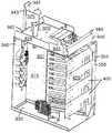
이제 도 33 을 참조하면, 섬유 분배 허브 (200'') 는 접근 칸막이 (1000) 에 장착될 수 있다. 접근 칸막이 (1000) 는 상부 패널 (1002), 바닥 패널 (1003), 우측 패널 (1004), 좌측 패널 (1006), 후방 패널 (1005) 및 전방 패널 (1008) 을 포함한다. 이러한 패널 (1002~1006 및 1008) 은 내부 (1020) 를 한정한다. 상부 패널 (1002) 은 캐비넷 (201'') 이 접근 칸막이 (1000) 에 장착되는 경우 캐비넷 (201'') 의 바닥 패널 (203') 내에 한정되는 개구와 정렬하도록 구성된 개구를 한정한다. 바닥 패널 (1003) 은 케이블 접근 개구를 한정한다.Referring now to FIG. 33, the
몇몇 실시형태에서, 공급자 케이블 (700) 및 가입자 케이블 (708) 은 접근 칸막이 (1000) 내부에서 캐비넷 (201') 으로부터 나온 스터브 케이블과 광학적으로 결합될 수 있다. 광학적 연결부는 전방 패널 (1008) 내에 한정된 개구를 통하여 접근 가능하다. 전방 패널 (1008) 내의 개구는 제거 가능한 접근 패널 (1010) 에 의해 또는 도어에 의해 보통 덮이게 된다.In some embodiments,
이제 도 34 를 참조하면, 캐비넷 (201'') 은 또 다른 스윙 프레임 (300'') 을 수용한다. 스윙 프레임 (300'') 은 캐비넷 (201'') 의 주 칸막이 (230') (도 31 참조) 내부에 피벗가능하게 장착된다. 일반적으로, 스윙 프레임 (300'') 은 상기 기술한 스윙 프레임 (300) 과 실질적으로 동일한 구성 요소 영역을 갖는다. 스윙 프레임 (300'') 은 스윙 프레임 (300) 으로부터 개조되었지만, 단말 레그 (410) 의 반대편의 각 단말 모듈 (400) 의 관리 레그 (420) 의 단부를 고정하기 위하여 스윙 프레임 (300'') 의 후방에 장착되는 프레임 부재 (360) 를 포함하도록 개조되었다.Referring now to FIG. 34,
프레임 부재 (360) 는 단말 모듈 (400) 에 대한 지지를 제공하며, 특히 케이블이 단말 모듈 (400) 을 통과하여 이어진 후 관리 레그 (420) 의 중량을 지지한다. 프레임 부재 (360) 는 일반적으로 스윙 프레임 (300'') 의 상부 패널 (320) 과 바닥 패널 (330) 사이에서 연장한다. 바람직한 실시형태에서, 프레임 부재 (360) 의 일 단부 (361) 는 바닥 패널 (330) 에 고정되고, 반대편 단부 (362) 는 상부 패널 (320) 의 플랜지 (324) 에 고정된다.The
스윙 프레임 (300'') 은 또한 스윙 프레임 (300'') 의 상부 패널 (320) 에 결합되는 램프 (ramp) (365) 를 포함한다. 이 램프 (365) 는 부분적인 섬유 스풀 (966) 및 굴곡 리미터 (968) 대신에 상부 패널의 단부 (329) 근방에 위치한다 (도 34 와 도 7 을 비교할 것). 램프 (365) 는 스윙 프레임 (300') 이 상부 패널 (320) 로부터 바닥 패널 (330) 로 전이될 때 섬유가 최소 굴곡 반경을 넘어 굴곡되는 것을 억제한다. 램프 (365) 는 또한 섬유의 초과 슬랙을 처리 (즉, 저장) 한다. 램프 (365) 는 섬유가 램프 (365) 의 측면 밖으로 빠져나오는 것을 억제하기 위한 탭 (368) 을 포함한다. 바람직한 실시형태에서 램프 (365) 는 제거 가능하다.The
상기 상세한 설명, 예 및 데이터는 본 발명의 제조 방법 및 구성의 용도를 완전히 설명한다. 본 발명의 원리 및 범위를 벗어나지 않으면서 다양한 실시형태가 만들어질 수 있으며, 본 발명은 이하 첨부된 청구항에 나타나 있다.The above detailed description, examples and data fully illustrate the use of the manufacturing methods and configurations of the present invention. Various embodiments may be made without departing from the spirit and scope of the invention, which is set forth in the appended claims below.
Claims (20)
Translated fromKoreanApplications Claiming Priority (7)
| Application Number | Priority Date | Filing Date | Title |
|---|---|---|---|
| US11/354,286 | 2006-02-13 | ||
| US11/354,286US7720343B2 (en) | 2006-02-13 | 2006-02-13 | Fiber distribution hub with swing frame and modular termination panels |
| US78381806P | 2006-03-17 | 2006-03-17 | |
| US60/783,818 | 2006-03-17 | ||
| US11/544,951 | 2006-10-06 | ||
| US11/544,951US7816602B2 (en) | 2006-02-13 | 2006-10-06 | Fiber distribution hub with outside accessible grounding terminals |
| PCT/US2007/003298WO2007095037A2 (en) | 2006-02-13 | 2007-02-07 | Fiber distribution hub with outside accessible grounding terminals |
Publications (2)
| Publication Number | Publication Date |
|---|---|
| KR20080100261Atrue KR20080100261A (en) | 2008-11-14 |
| KR101369118B1 KR101369118B1 (en) | 2014-03-04 |
Family
ID=38304217
Family Applications (1)
| Application Number | Title | Priority Date | Filing Date |
|---|---|---|---|
| KR1020087022475AExpired - Fee RelatedKR101369118B1 (en) | 2006-02-13 | 2007-02-07 | Fiber distribution hub with outside accessible grounding terminals |
Country Status (10)
| Country | Link |
|---|---|
| US (8) | US7816602B2 (en) |
| EP (1) | EP1987385B1 (en) |
| JP (1) | JP2009527006A (en) |
| KR (1) | KR101369118B1 (en) |
| AT (1) | ATE536562T1 (en) |
| AU (1) | AU2007215422B2 (en) |
| BR (1) | BRPI0707783B1 (en) |
| MX (1) | MX2008009515A (en) |
| TW (1) | TWI444684B (en) |
| WO (1) | WO2007095037A2 (en) |
Families Citing this family (108)
| Publication number | Priority date | Publication date | Assignee | Title |
|---|---|---|---|---|
| WO2006135524A2 (en)* | 2005-05-18 | 2006-12-21 | Corning Cable Systems Llc | High density optical fiber distribution enclosure |
| JP5479733B2 (en) | 2005-07-15 | 2014-04-23 | オーバーン ユニバーシティ | Microscope illumination device and adapter |
| US7623749B2 (en) | 2005-08-30 | 2009-11-24 | Adc Telecommunications, Inc. | Fiber distribution hub with modular termination blocks |
| US7816602B2 (en) | 2006-02-13 | 2010-10-19 | Adc Telecommunications, Inc. | Fiber distribution hub with outside accessible grounding terminals |
| US7711234B2 (en) | 2006-10-02 | 2010-05-04 | Adc Telecommunications, Inc. | Reskinnable fiber distribution hub |
| US7349616B1 (en) | 2007-01-12 | 2008-03-25 | Corning Cable Systems Llc | Fiber optic local convergence points for multiple dwelling units |
| US7522805B2 (en)* | 2007-03-09 | 2009-04-21 | Adc Telecommunications, Inc. | Wall mount distribution arrangement |
| US20090310929A1 (en)* | 2007-10-10 | 2009-12-17 | Adc Telecommunications, Inc. | Optical fiber interconnection apparatus |
| US7720344B2 (en)* | 2007-10-22 | 2010-05-18 | Adc Telecommunications, Inc. | Fiber distribution hub |
| WO2009058928A1 (en)* | 2007-10-30 | 2009-05-07 | The Siemon Company | Vertical patching system |
| US7751672B2 (en) | 2007-10-31 | 2010-07-06 | Adc Telecommunications, Inc. | Low profile fiber distribution hub |
| US7860365B2 (en)* | 2007-11-16 | 2010-12-28 | Adc Telecommunications, Inc. | Edge protector for fiber optic cable routing |
| US8229265B2 (en) | 2007-11-21 | 2012-07-24 | Adc Telecommunications, Inc. | Fiber distribution hub with multiple configurations |
| US8238709B2 (en) | 2007-12-18 | 2012-08-07 | Adc Telecommunications, Inc. | Multi-configuration mounting system for fiber distribution hub |
| US7715682B2 (en)* | 2008-03-04 | 2010-05-11 | Adc Telecommunications, Inc. | Fiber distribution hub having an adjustable plate |
| US20090277681A1 (en)* | 2008-04-04 | 2009-11-12 | Musolf Bruce R | Expansion cross-connect enclosure |
| US7795533B2 (en)* | 2008-07-03 | 2010-09-14 | Panduit Corp. | In-ceiling zone cabling enclosure |
| US8599535B2 (en)* | 2009-01-08 | 2013-12-03 | Oscar G. Loayza | System and apparatus for managing and organizing electrical cords and cables |
| DE202009000621U1 (en)* | 2009-01-15 | 2009-03-19 | CCS Technology, Inc., Wilmington | Optical fiber distribution device |
| US8380036B2 (en)* | 2009-01-20 | 2013-02-19 | Adc Telecommunications, Inc. | Splitter module with connectorized pigtail manager |
| CN106130646B (en) | 2009-03-05 | 2019-04-30 | Adc电信公司 | Methods, systems and apparatus for integrating wireless technologies into fiber optic networks |
| JP4920723B2 (en)* | 2009-05-14 | 2012-04-18 | シャープ株式会社 | Transmission system for image display device and electronic device |
| ES2403007A1 (en)* | 2009-07-01 | 2013-05-13 | Adc Telecommunications, Inc | Wall-mounted fiber distribution hub |
| US8606067B2 (en)* | 2009-09-04 | 2013-12-10 | Adc Telecommunications, Inc. | Pedestal terminal with swing frame |
| US8428419B2 (en) | 2009-09-23 | 2013-04-23 | Adc Telecommunications, Inc. | Fiber distribution hub with internal cable spool |
| US9078287B2 (en) | 2010-04-14 | 2015-07-07 | Adc Telecommunications, Inc. | Fiber to the antenna |
| US8837940B2 (en) | 2010-04-14 | 2014-09-16 | Adc Telecommunications, Inc. | Methods and systems for distributing fiber optic telecommunication services to local areas and for supporting distributed antenna systems |
| WO2011140461A2 (en) | 2010-05-07 | 2011-11-10 | Adc Telecommunications, Inc. | Fiber distribution hub with pass-through interfaces |
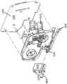
| JP5392194B2 (en)* | 2010-06-15 | 2014-01-22 | コベルコ建機株式会社 | Electrical equipment storage equipment for construction machinery |
| US8514551B2 (en) | 2010-06-17 | 2013-08-20 | Diversified Control, Inc. | Panelboard enclosure with external power cutoff switch |
| FR2963603B1 (en)* | 2010-08-03 | 2013-05-17 | Eri | VIDEO DISPLAY DEVICE, IN PARTICULAR FOR MONITORING THE RISE AND DESCENT OF TRAVELERS OF A TRAIN |
| WO2012054454A2 (en) | 2010-10-19 | 2012-04-26 | Corning Cable Systems Llc | Transition box for multiple dwelling unit fiber optic distribution network |
| WO2012058391A1 (en) | 2010-10-28 | 2012-05-03 | Corning Cable Systems Llc | Impact resistant fiber optic enclosures and related methods |
| US9560777B2 (en) | 2010-11-08 | 2017-01-31 | Chatsworth Products, Inc. | Door closer mechanism for hot/cold aisle air containment room |
| US8902570B2 (en) | 2010-12-23 | 2014-12-02 | Diversified Control, Inc. | Panelboard enclosure with improved external power cutoff switch |
| US8456806B2 (en)* | 2011-01-08 | 2013-06-04 | Diversified Control, Inc. | Panelboard enclosure with manually operable load disconnector |
| US8582279B2 (en)* | 2011-02-04 | 2013-11-12 | Eaton Corporation | Side accessible circuit breaker to bus connections |
| US9279950B2 (en)* | 2011-03-28 | 2016-03-08 | Afl Telecommunications Llc | Exterior distribution pedestal cabinet |
| WO2012138440A1 (en)* | 2011-04-04 | 2012-10-11 | Afl Telecommunications Llc | Optical fiber distribution cabinet for outdoor use |
| US9134496B2 (en)* | 2011-05-19 | 2015-09-15 | Communication Systems, Inc. | Modular plug and play connectivity platform |
| CA2877896C (en) | 2011-06-24 | 2020-07-21 | Adc Telecommunications, Inc. | Fiber termination enclosure with modular plate assemblies |
| US8717744B2 (en)* | 2011-10-25 | 2014-05-06 | General Electric Company | Fuse cover |
| US9069151B2 (en) | 2011-10-26 | 2015-06-30 | Corning Cable Systems Llc | Composite cable breakout assembly |
| US9219546B2 (en) | 2011-12-12 | 2015-12-22 | Corning Optical Communications LLC | Extremely high frequency (EHF) distributed antenna systems, and related components and methods |
| USD684128S1 (en)* | 2012-02-10 | 2013-06-11 | Chatsworth Products, Inc. | Containment aisle door |
| US11246231B2 (en) | 2012-02-10 | 2022-02-08 | Chatsworth Products, Inc. | Door closer mechanism for hot/cold aisle air containment room |
| CN202453678U (en)* | 2012-02-13 | 2012-09-26 | 施耐德电器工业公司 | Man-machine interface device and control cabinet comprising same |
| US10110307B2 (en) | 2012-03-02 | 2018-10-23 | Corning Optical Communications LLC | Optical network units (ONUs) for high bandwidth connectivity, and related components and methods |
| US8873926B2 (en) | 2012-04-26 | 2014-10-28 | Corning Cable Systems Llc | Fiber optic enclosures employing clamping assemblies for strain relief of cables, and related assemblies and methods |
| ES1141660Y (en) | 2012-12-19 | 2015-10-14 | Tyco Electronics Raychem Bvba | Distribution device with incrementally added dividers |
| US9606315B2 (en)* | 2013-03-15 | 2017-03-28 | All Systems Broadband, Inc. | Optical fiber ribbon storage |
| US9344776B2 (en) | 2013-05-29 | 2016-05-17 | Go!Foton Holdings, Inc. | Patch panel tray assembly |
| US20150077935A1 (en)* | 2013-09-13 | 2015-03-19 | Anue Systems, Inc. | Air Filter And Cable Management Assemblies For Network Communication Systems |
| DK177926B1 (en)* | 2013-12-20 | 2015-01-12 | Fritz Schur Energy As | Pitch actuator arrangement |
| ES2711092T3 (en) | 2014-04-03 | 2019-04-30 | CommScope Connectivity Belgium BVBA | Divider module and enclosure for use in the same |
| JP2017520887A (en) | 2014-06-05 | 2017-07-27 | チャッツワース プロダクツ、インク. | Electrical outlet with locking mechanism |
| AU2015276109B2 (en) | 2014-06-17 | 2020-11-19 | Adc Czech Republic, S.R.O. | Cable distribution system |
| US9540136B2 (en)* | 2014-08-22 | 2017-01-10 | Caterpillar Inc. | Control box for generator set |
| US9442266B2 (en) | 2014-09-11 | 2016-09-13 | Commscope Technologies Llc | Fiber optic enclosure for retrofitting pedestals in the field |
| US9882362B2 (en) | 2014-09-23 | 2018-01-30 | Ppc Broadband, Inc. | Enclosure for controling access to different telecommunication components |
| US10976512B2 (en) | 2014-09-23 | 2021-04-13 | Ppc Broadband, Inc. | House box with mounting surface for mounted access |
| WO2016049242A1 (en) | 2014-09-23 | 2016-03-31 | Ppc Broadband, Inc. | Universal multi-purpose compartmentalized telecommunications box |
| US10509187B2 (en) | 2014-09-23 | 2019-12-17 | Ppc Broadband, Inc. | Universal multi-purpose compartmentalized telecommunications box |
| US20160095238A1 (en)* | 2014-09-26 | 2016-03-31 | Jeremy Krinitt | Security Panel Enclosure and Mounting System |
| US10012814B2 (en) | 2014-10-01 | 2018-07-03 | Clearfield, Inc. | Optical fiber management |
| MX386723B (en)* | 2014-12-09 | 2025-03-19 | Ppc Broadband Inc | UNIVERSAL MULTIPURPOSE COMPARTMENTED TELECOMMUNICATIONS BOX. |
| CN104516076B (en)* | 2014-12-26 | 2017-09-29 | 宁波市令通电信设备有限公司 | A kind of combined distribution frame |
| EP3822676A1 (en) | 2015-04-02 | 2021-05-19 | CommScope Technologies LLC | Fiber optic network architecture using high fiber-count fiber optic connectors |
| US9851523B2 (en) | 2015-09-22 | 2017-12-26 | Go!Foton Holdings, Inc. | Apparatus for cable routing |
| CN105278064A (en)* | 2015-11-04 | 2016-01-27 | 重庆德为通信技术有限公司 | Compact type light-splitting fiber distribution box |
| US9632269B1 (en)* | 2015-11-25 | 2017-04-25 | Corning Optical Communications LLC | Systems for stacking modular fiber optic cabinets, and related devices, components, and methods |
| US10606009B2 (en) | 2015-12-01 | 2020-03-31 | CommScope Connectivity Belgium BVBA | Cable distribution system with fan out devices |
| EP3408701B1 (en) | 2016-01-28 | 2023-04-26 | CommScope Connectivity Belgium BVBA | Modular telecommunications enclosure |
| WO2017162751A1 (en) | 2016-03-23 | 2017-09-28 | CommScope Connectivity Belgium BVBA | Module and enclosure for use therein |
| US10735838B2 (en) | 2016-11-14 | 2020-08-04 | Corning Optical Communications LLC | Transparent wireless bridges for optical fiber-wireless networks and related methods and systems |
| US10291969B2 (en) | 2017-02-14 | 2019-05-14 | Go!Foton Holdings, Inc. | Rear cable management |
| US10310206B2 (en) | 2017-05-22 | 2019-06-04 | Go!Foton Holdings, Inc. | Apparatus for cable routing |
| WO2018222740A1 (en) | 2017-05-30 | 2018-12-06 | Commscope Technologies Llc | Reconfigurable optical networks |
| US10935745B1 (en)* | 2017-07-20 | 2021-03-02 | Forrest Tyrone Gay | Multi-carrier fiber distribution hub |
| EP3673308B1 (en)* | 2017-08-23 | 2024-04-03 | Commscope Technologies LLC | Drop terminal |
| CN108227100A (en)* | 2017-12-28 | 2018-06-29 | 南京普天通信股份有限公司 | A kind of outdoor photoelectricity integrated box |
| US10218158B1 (en)* | 2018-01-08 | 2019-02-26 | Siemens Industry, Inc. | Electrical power distribution assemblies including pivotable compartment component, rotatable compartment assemblies, and operational servicing methods |
| US10547145B2 (en) | 2018-02-05 | 2020-01-28 | Chatworth Products, Inc. | Electric receptacle with locking feature |
| US10509180B2 (en)* | 2018-02-08 | 2019-12-17 | Ciena Corporation | Flexible routing in a fiber tray for use in a fiber optic assembly |
| US11169344B2 (en) | 2018-02-27 | 2021-11-09 | Commscope Technologies Llc | Common module storage within a fiber distribution hub |
| US10416406B1 (en) | 2018-03-01 | 2019-09-17 | Afl Telecommunications Llc | Communications module housing |
| US10884209B2 (en) | 2018-05-11 | 2021-01-05 | Clearfield, Inc. | Optical fiber distribution cabinet |
| US12169318B2 (en) | 2018-08-20 | 2024-12-17 | Commscope Technologies Llc | Telecommunications equipment frame |
| US10912217B2 (en) | 2018-08-22 | 2021-02-02 | Enclosures Unlimited Inc. | Enclosure for electrical equipment |
| WO2020040913A1 (en)* | 2018-08-24 | 2020-02-27 | Commscope Technologies Llc | Hybrid enclosures for power and optical fiber, and enclosures including multiple protective lids |
| US10451828B1 (en) | 2018-11-09 | 2019-10-22 | Afl Telecommunications Llc | Communications module housing |
| US11196240B2 (en)* | 2019-01-31 | 2021-12-07 | Ampthink, Llc | Cable junction enclosure |
| GB2577761B (en)* | 2019-02-15 | 2020-10-28 | Wolseley Uk Ltd | Enclosures for gas and electricity meters |
| US11122701B2 (en)* | 2019-02-15 | 2021-09-14 | Hubbell Incorporated | Wall mounted utility cabinet |
| WO2021055779A1 (en)* | 2019-09-20 | 2021-03-25 | Commscope Technologies Llc | Powered fiber distribution hub |
| WO2021071844A1 (en) | 2019-10-07 | 2021-04-15 | Commscope Technologies Llc | Fiber distribution hub including sealed splice module |
| CN110933897B (en)* | 2019-12-05 | 2020-10-27 | 湖北智建芯云科技有限公司 | Highly integrated diversified force calculation frame |
| US11083102B1 (en)* | 2019-12-10 | 2021-08-03 | Amazon Technologies, Inc. | Modular distribution frames and assemblies |
| US11310923B2 (en) | 2020-01-06 | 2022-04-19 | Enclosures Unlimited Inc. | Enclosure for electrical equipment |
| EP3971622A1 (en) | 2020-07-02 | 2022-03-23 | Go!Foton Holdings, Inc. | Intelligent optical switch |
| EP4176229A4 (en)* | 2020-07-03 | 2024-08-14 | Invision AI, Inc. | Video-based tracking systems and methods |
| RU201888U1 (en)* | 2020-07-19 | 2021-01-20 | Николай Викторович Дульцев | LOW-VOLTAGE CHARGER-RECTIFIER CABINET |
| EP4154368A4 (en)* | 2020-07-24 | 2024-07-17 | Schneider Electric USA, Inc. | BUS BRIDGE FOR MODULAR DISTRIBUTION BOARD |
| US11835555B2 (en)* | 2021-06-09 | 2023-12-05 | E.J. Brooks Company | Multiple watthour meter assembly |
| CN114217401A (en)* | 2021-12-23 | 2022-03-22 | 安徽森联信息科技有限公司 | A quick wiring arrangement for three networks fuses optic fibre |
| DE102023113178B3 (en)* | 2023-05-19 | 2024-07-04 | Connect Com GmbH | Distribution device with pivoting splice cassette holder |
| US11962343B1 (en)* | 2023-09-29 | 2024-04-16 | Frontier Communications Holdings, Llc | Method for identifying and highlighting available fibers in a fiber distribution hub |
| US20250125599A1 (en)* | 2023-10-12 | 2025-04-17 | Ppc Broadband, Inc. | Enclosure structurally configured to provide enhanced access to an electronic component mounted in the enclosure |
Family Cites Families (157)
| Publication number | Priority date | Publication date | Assignee | Title |
|---|---|---|---|---|
| US4792203A (en) | 1985-09-17 | 1988-12-20 | Adc Telecommunications, Inc. | Optical fiber distribution apparatus |
| US4831403A (en) | 1985-12-27 | 1989-05-16 | Minolta Camera Kabushiki Kaisha | Automatic focus detection system |
| US4747020A (en) | 1986-05-16 | 1988-05-24 | Adc Telecommunications, Inc. | Wire distribution apparatus |
| US4736100A (en) | 1986-07-31 | 1988-04-05 | Amp Incorporated | Optical loop attenuator simulating an optical system |
| JPS63229409A (en) | 1987-03-18 | 1988-09-26 | Matsushita Electric Ind Co Ltd | Light emitting/light receiving module |
| US4824196A (en) | 1987-05-26 | 1989-04-25 | Minnesota Mining And Manufacturing Company | Optical fiber distribution panel |
| US5069636A (en) | 1987-07-07 | 1991-12-03 | Raychem Corporation | Terminal block and adapter |
| FR2633061B1 (en) | 1988-06-20 | 1992-02-14 | Telecommunications Sa | BREWING, DISTRIBUTION AND / OR CONNECTION MODULE FOR OPTICAL FIBERS AND ITS APPLICATIONS |
| US4861134A (en) | 1988-06-29 | 1989-08-29 | American Telephone And Telegraph Company, At&T Bell Laboratories | Opto-electronic and optical fiber interface arrangement |
| US4900123A (en) | 1988-08-29 | 1990-02-13 | Gte Products Corporation | 1550 nm fiber distribution panel |
| US4995688A (en) | 1989-07-31 | 1991-02-26 | Adc Telecommunications, Inc. | Optical fiber distribution frame |
| US5202538A (en)* | 1990-03-20 | 1993-04-13 | Union Connector Co., Inc. | Portable power distribution cabinet |
| US5076688A (en) | 1990-03-23 | 1991-12-31 | Amp Incorporated | Optical simulator with loop-back attenuator having metalized optical fiber |
| EP0530325B1 (en) | 1990-05-21 | 1997-03-05 | Minnesota Mining And Manufacturing Company | Optical fiber distribution center |
| US5073042A (en) | 1990-06-21 | 1991-12-17 | Amp Incorporated | Coupling bushing for various types of optical fiber connectors |
| US5136463A (en)* | 1991-04-05 | 1992-08-04 | Reliance Comm/Tec Corporation | Universal enclosure with electrical panel |
| US5142598A (en) | 1991-08-28 | 1992-08-25 | Porta Systems Corp. | Fiber optic connector having snap ring adjustment means |
| US5233674A (en) | 1991-11-21 | 1993-08-03 | Methode Electronics, Inc. | Fiber optic connector with sliding tab release |
| FR2685851B1 (en) | 1991-12-30 | 1994-02-04 | Alcatel Cit | DEVICE FOR SUPPORTING AND GUIDING CABLES FOR TRANSMITTING ELECTRIC OR LIGHT SIGNALS. |
| US5247603A (en)* | 1992-01-24 | 1993-09-21 | Minnesota Mining And Manufacturing Company | Fiber optic connection system with exchangeable cross-connect and interconnect cards |
| US5214735A (en) | 1992-04-06 | 1993-05-25 | Adc Telecommunications, Inc. | Fiber optic connector retainer |
| US5333221A (en) | 1992-06-30 | 1994-07-26 | The Whitaker Corporation | Universal adapter for optical connectors |
| US5274729A (en) | 1992-07-30 | 1993-12-28 | At&T Bell Laboratories | Universal optical fiber buildout system |
| US5274731A (en) | 1992-12-24 | 1993-12-28 | Adc Telecommunications, Inc. | Optical fiber cabinet |
| GB9307488D0 (en) | 1993-04-08 | 1993-06-02 | Amp Holland | Optical fibre connector latching mechanism |
| US5333222A (en) | 1993-05-14 | 1994-07-26 | Molex Incorporated | Adapter for interconnecting optical fiber connectors or the like |
| US5317663A (en) | 1993-05-20 | 1994-05-31 | Adc Telecommunications, Inc. | One-piece SC adapter |
| GB9318632D0 (en)* | 1993-09-08 | 1993-10-27 | Raychem Sa Nv | Optical fibre organizer |
| US5367598A (en) | 1993-10-21 | 1994-11-22 | Nec America, Inc. | Interface chassis for fiber optic transport system |
| US5469526A (en) | 1994-01-07 | 1995-11-21 | Porta Systems Corp. | Optical fiber support for printed circuit boards |
| TW232757B (en) | 1994-01-21 | 1994-10-21 | Adc Telecommunications Inc | High-density fiber distribution frame |
| US5442726A (en) | 1994-02-22 | 1995-08-15 | Hubbell Incorporated | Optical fiber storage system |
| US5402515A (en) | 1994-03-01 | 1995-03-28 | Minnesota Mining And Manufacturing Company | Fiber distribution frame system, cabinets, trays and fiber optic connector couplings |
| US5359688A (en) | 1994-03-04 | 1994-10-25 | Siecor Corporation | Metal internal holding clips for fiber optic connector coupling |
| GB9405535D0 (en) | 1994-03-21 | 1994-05-04 | Raychem Sa Nv | Splice organizing apparatus |
| US5408557A (en) | 1994-04-20 | 1995-04-18 | Hsu; Chung-Tang | FC-type optical fiber cable connector's adaptor |
| US5511144A (en) | 1994-06-13 | 1996-04-23 | Siecor Corporation | Optical distribution frame |
| US6188687B1 (en) | 1994-11-30 | 2001-02-13 | Verizon Laboratories Inc. | Broadband switch that manages traffic and method therefor |
| JP3464553B2 (en) | 1995-03-06 | 2003-11-10 | 富士通株式会社 | Subrack equipment |
| TW358552U (en) | 1995-08-02 | 1999-05-11 | Molex Inc | Adapter for interconnecting optical fiber connectors |
| JP3022015U (en)* | 1995-08-24 | 1996-03-12 | モレックス インコーポレーテッド | Fiber Optic Cable Connector |
| US5647043A (en) | 1995-10-12 | 1997-07-08 | Lucent Technologies, Inc. | Unipartite jack receptacle |
| US5734774A (en) | 1995-11-30 | 1998-03-31 | Lucent Technologies Inc. | Outdoor electronics cabinet |
| JPH09211264A (en) | 1996-02-01 | 1997-08-15 | Molex Inc | Adapter for optical fiber connector |
| US5758003A (en) | 1996-03-15 | 1998-05-26 | Adc Telecommunications, Inc. | High density fiber management |
| US5790548A (en) | 1996-04-18 | 1998-08-04 | Bell Atlantic Network Services, Inc. | Universal access multimedia data network |
| US5708751A (en) | 1996-04-24 | 1998-01-13 | Tii Industries, Inc. | Optical fiber enclosure system |
| US6353183B1 (en) | 1996-05-23 | 2002-03-05 | The Siemon Company | Adapter plate for use with cable adapters |
| US5734776A (en) | 1996-08-28 | 1998-03-31 | Adc Telecommunications, Inc. | Outside plant cross-connect apparatus |
| US5825955A (en) | 1997-02-05 | 1998-10-20 | Molex Incorporated | Fiber optic diversion connector |
| US5956444A (en) | 1997-02-13 | 1999-09-21 | Amphenol Corporation | Radiation absorbing shield for fiber optic systems |
| US6061492A (en) | 1997-04-09 | 2000-05-09 | Siecor Corporation | Apparatus and method for interconnecting fiber cables |
| US5883995A (en) | 1997-05-20 | 1999-03-16 | Adc Telecommunications, Inc. | Fiber connector and adapter |
| US5823646A (en) | 1997-09-02 | 1998-10-20 | Siecor Corporation | Door assembly for optical hardware cabinet |
| JPH11108751A (en) | 1997-10-08 | 1999-04-23 | Ishida Co Ltd | Measuring device with filter automatic regulating function |
| US6227717B1 (en) | 1997-12-16 | 2001-05-08 | The Siemon Company | Dust caps for use with telecommunications adapters and connectors |
| US6027252A (en) | 1997-12-19 | 2000-02-22 | The Whitaker Corporation | Simplified fiber optic receptacle |
| US5969294A (en) | 1997-12-31 | 1999-10-19 | Siecor Operations, Llc | Fiber optic connector cabinet with rotatably mounted adapter panels |
| US6023458A (en) | 1998-01-26 | 2000-02-08 | Gte Laboratories Incorporated | Method and system for distributing subscriber services using wireless bidirectional broadband loops |
| US6079881A (en) | 1998-04-08 | 2000-06-27 | Molex Incorporated | Fiber optic connector receptacle assembly |
| TW362839U (en) | 1998-04-10 | 1999-06-21 | Wan-Ding Wu | Extraction type terminal wiring box |
| US5930425A (en) | 1998-04-21 | 1999-07-27 | Lucent Technologies Inc. | High density coupling module |
| US6359217B1 (en)* | 1998-06-05 | 2002-03-19 | Trendway Corporation | Cabinet with electrical/data conduit routing capabilities |
| US6169249B1 (en)* | 1998-06-30 | 2001-01-02 | Emc Corporation | Electrical cabinet having a bulkhead with electrical connectors |
| US6044193A (en) | 1998-07-10 | 2000-03-28 | Siecor Operations, Llc | Fiber optic interconnection enclosure having a forced air system |
| US6208796B1 (en) | 1998-07-21 | 2001-03-27 | Adc Telecommunications, Inc. | Fiber optic module |
| KR100377823B1 (en) | 1998-07-24 | 2003-03-26 | 니폰덴신뎅와 가부시키가이샤 | Board and system for distributing optical fibers |
| US6160946A (en) | 1998-07-27 | 2000-12-12 | Adc Telecommunications, Inc. | Outside plant fiber distribution apparatus and method |
| US6035029A (en) | 1998-08-24 | 2000-03-07 | Bell Atlantic Network Services, Inc. | System and method for subscriber line service control |
| US6480487B1 (en) | 1998-08-24 | 2002-11-12 | Verizon Services Group | Digital loop carrier remote terminal having integrated digital subscriber plug-in line cards for multiplexing of telephone and broadband signals |
| US6149315A (en) | 1998-09-04 | 2000-11-21 | Lucent Technologies Inc. | Side load resistant buildout |
| US6347888B1 (en) | 1998-11-23 | 2002-02-19 | Adc Telecommunications, Inc. | Fiber optic adapter, including hybrid connector system |
| US6240229B1 (en) | 1998-12-21 | 2001-05-29 | Molex Incorporated | Connector assembly |
| US6535682B1 (en) | 1999-03-01 | 2003-03-18 | Adc Telecommunications, Inc. | Optical fiber distribution frame with connector modules |
| US6556763B1 (en) | 1999-03-01 | 2003-04-29 | Adc Telecommunications, Inc. | Optical fiber distribution frame with connector modules |
| US6760531B1 (en) | 1999-03-01 | 2004-07-06 | Adc Telecommunications, Inc. | Optical fiber distribution frame with outside plant enclosure |
| US6424781B1 (en) | 1999-03-01 | 2002-07-23 | Adc Telecommunications, Inc. | Optical fiber distribution frame with pivoting connector panels |
| US6431762B1 (en) | 1999-04-09 | 2002-08-13 | Seiko Instruments Inc. | Optical connector adapter |
| US6188825B1 (en) | 1999-04-15 | 2001-02-13 | Lucent Technologies, Inc. | Dust cover for protecting optical fiber sleeve housing |
| US6241200B1 (en)* | 1999-04-30 | 2001-06-05 | Lucent Technologies Inc. | Electromagnetic interference grouping clamp |
| US6356697B1 (en) | 1999-05-04 | 2002-03-12 | Sumitomo Electric Lightwave Corp. | Optical fiber cable distribution shelf with pivotably mounted trays |
| US6278829B1 (en) | 1999-05-05 | 2001-08-21 | Marconi Communications, Inc. | Optical fiber routing and support apparatus |
| US6236795B1 (en) | 1999-06-07 | 2001-05-22 | E. Walter Rodgers | High-density fiber optic cable distribution frame |
| US6464402B1 (en) | 1999-07-28 | 2002-10-15 | Fitel Usa Corp. | Optical fiber connector tuning index tool |
| US6539147B1 (en) | 1999-08-12 | 2003-03-25 | Bellsouth Intellectual Property Corporation | Connectorized inside fiber optic drop |
| US6522804B1 (en) | 1999-08-12 | 2003-02-18 | Bellsouth Intellectual Property Corporation | Connectorized outside fiber optic drop |
| US6496641B1 (en) | 1999-08-12 | 2002-12-17 | Bellsouth Intellectual Property Corporation | Fiber optic interface device |
| US6411767B1 (en) | 1999-08-24 | 2002-06-25 | Corning Cable Systems Llc | Optical fiber interconnection closures |
| US6234683B1 (en) | 1999-09-13 | 2001-05-22 | Stratos Lightwave, Inc. | Field repairable hermaphroditic connector |
| US6385381B1 (en) | 1999-09-21 | 2002-05-07 | Lucent Technologies Inc. | Fiber optic interconnection combination closure |
| US6577595B1 (en) | 1999-11-12 | 2003-06-10 | Genuity Inc. | Systems and methods for transporting associated data signals over a network |
| SE521276C2 (en)* | 1999-11-18 | 2003-10-14 | Ericsson Telefon Ab L M | Multi-carrier type transmission system |
| US6496640B1 (en) | 1999-12-16 | 2002-12-17 | Corning Cable Systems Llc | Splice closure with removable and pivotable splice trays, and associated methods |
| US6418262B1 (en)* | 2000-03-13 | 2002-07-09 | Adc Telecommunications, Inc. | Fiber distribution frame with fiber termination blocks |
| US6394398B1 (en)* | 2000-06-22 | 2002-05-28 | Chatsworth Products, Inc. | Modular inter-cabinet horizontal cable support apparatus |
| US6360050B1 (en)* | 2000-09-08 | 2002-03-19 | Telect, Inc. | High density fiber distribution tray system |
| US6554485B1 (en) | 2000-09-11 | 2003-04-29 | Corning Cable Systems Llc | Translucent dust cap and associated method for testing the continuity of an optical fiber jumper |
| US6920213B2 (en) | 2000-09-15 | 2005-07-19 | Verizon Services Corp. | Methods and apparatus for facilitating the interaction between multiple telephone and computer users |
| US6425694B1 (en) | 2000-09-18 | 2002-07-30 | Molex Incorporated | Fiber optic receptacle with protective shutter |
| US6788786B1 (en) | 2000-09-22 | 2004-09-07 | Adc Telecommunications, Inc. | Multimedia patching box |
| US6539160B2 (en) | 2000-10-27 | 2003-03-25 | Corning Cable Systems Llc | Optical fiber splicing and connecting assembly with coupler cassette |
| US6542688B1 (en) | 2000-10-27 | 2003-04-01 | Corning Cable Systems Llc | Optical fiber splicing and connecting assembly |
| US6434313B1 (en) | 2000-10-31 | 2002-08-13 | Corning Cable Systems Llc | Fiber optic closure with couplers and splice tray |
| US6661961B1 (en) | 2000-11-01 | 2003-12-09 | Tyco Electronics Corporation | Fiber low profile network interface device |
| USD466087S1 (en) | 2001-01-30 | 2002-11-26 | Nexans | Optical fiber connection cabinet |
| US6978062B2 (en)* | 2001-02-21 | 2005-12-20 | Ibsen Photonics A/S | Wavelength division multiplexed device |
| US6631237B2 (en) | 2001-03-06 | 2003-10-07 | Adc Telecommunications, Inc. | Termination and splice panel |
| US6945616B2 (en)* | 2001-04-02 | 2005-09-20 | Emerson Network Power, Energy Systems, North America, Inc. | Modular enclosure system for electronic equipment |
| US6654536B2 (en) | 2001-04-12 | 2003-11-25 | Corning Cable Systems Llc | Fiber management frame having connector platform |
| US6483977B2 (en) | 2001-04-12 | 2002-11-19 | Corning Cable Systems Llc | Fiber management frame having movable work platform |
| US6792190B2 (en) | 2001-06-01 | 2004-09-14 | Telect, Inc. | High density fiber optic splitter/connector tray system |
| US6804352B2 (en)* | 2001-06-29 | 2004-10-12 | Adc Telecommunications, Inc. | High circuit density pots splitter assembly |
| US6657123B2 (en)* | 2001-10-01 | 2003-12-02 | Tampa Armature Works, Inc. | Power distribution cabinet |
| US6591051B2 (en) | 2001-11-16 | 2003-07-08 | Adc Telecommunications, Inc. | Fiber termination block with angled slide |
| US6621975B2 (en) | 2001-11-30 | 2003-09-16 | Corning Cable Systems Llc | Distribution terminal for network access point |
| US6909833B2 (en) | 2002-03-15 | 2005-06-21 | Fiber Optic Network Solutions, Inc. | Optical fiber enclosure system using integrated optical connector and coupler assembly |
| DE10211826C1 (en) | 2002-03-16 | 2003-09-25 | Krone Gmbh | Terminal rail connector plug has contact elements cooperating with terminal rails provided by metallised structure within plastics lower half of connector plug |
| US7093997B2 (en) | 2002-03-27 | 2006-08-22 | Adc Telecommunications, Inc. | Coupler for cable trough |
| US6850685B2 (en) | 2002-03-27 | 2005-02-01 | Adc Telecommunications, Inc. | Termination panel with pivoting bulkhead and cable management |
| US6980725B1 (en) | 2002-04-30 | 2005-12-27 | Calix Networks, Inc. | Space reuse during technology upgrade in a protection area of an outdoor enclosure |
| US7230836B2 (en) | 2002-05-10 | 2007-06-12 | Purcell Systems, Inc. | Remote enclosure systems and methods of production thereof |
| CA2461029C (en)* | 2002-05-10 | 2005-08-09 | Purcell Systems, Inc. | Remote enclosure systems and methods of production thereof |
| US6778752B2 (en) | 2002-05-31 | 2004-08-17 | Corning Cable Systems Llc | Below grade closure for local convergence point |
| TW547864U (en) | 2002-07-22 | 2003-08-11 | Advanced Optronics Corp | Digital wire distribution box of telecommunication system |
| US6715619B2 (en)* | 2002-07-22 | 2004-04-06 | Adc Telecommunications, Inc. | Fiber management drawer and patch panel |
| JP2006502445A (en) | 2002-10-11 | 2006-01-19 | スリーエム イノベイティブ プロパティズ カンパニー | Fiber management drawer |
| US6815612B2 (en) | 2002-10-18 | 2004-11-09 | Corning Cable Systems Llc | Watertight seal for network interface device |
| US7086539B2 (en) | 2002-10-21 | 2006-08-08 | Adc Telecommunications, Inc. | High density panel with rotating tray |
| US6700062B1 (en)* | 2003-01-10 | 2004-03-02 | Philip Brown Allen, Jr. | Device for providing access to electrical connections to enclosure |
| DE10307944B4 (en) | 2003-02-25 | 2005-08-18 | Berthold Sichert Gmbh | Retractable distribution cabinet |
| US7142764B2 (en) | 2003-03-20 | 2006-11-28 | Tyco Electronics Corporation | Optical fiber interconnect cabinets, termination modules and fiber connectivity management for the same |
| US6792191B1 (en) | 2003-04-22 | 2004-09-14 | Corning Cable Systems Llc | Local convergence cabinet |
| US6870734B2 (en) | 2003-05-30 | 2005-03-22 | Adc Telecommunications, Inc. | Fiber containment system |
| US7198409B2 (en) | 2003-06-30 | 2007-04-03 | Adc Telecommunications, Inc. | Fiber optic connector holder and method |
| US7233731B2 (en) | 2003-07-02 | 2007-06-19 | Adc Telecommunications, Inc. | Telecommunications connection cabinet |
| US7090816B2 (en) | 2003-07-17 | 2006-08-15 | Kellogg Brown & Root Llc | Low-delta P purifier for nitrogen, methane, and argon removal from syngas |
| US6983095B2 (en) | 2003-11-17 | 2006-01-03 | Fiber Optic Network Solutions Corporation | Systems and methods for managing optical fibers and components within an enclosure in an optical communications network |
| US7369741B2 (en) | 2003-11-17 | 2008-05-06 | Fiber Optics Network Solutions Corp. | Storage adapter with dust cap posts |
| US6920274B2 (en) | 2003-12-23 | 2005-07-19 | Adc Telecommunications, Inc. | High density optical fiber distribution frame with modules |
| JP2005222749A (en) | 2004-02-04 | 2005-08-18 | Kel Corp | Connector for coaxial cable |
| US7218827B2 (en) | 2004-06-18 | 2007-05-15 | Adc Telecommunications, Inc. | Multi-position fiber optic connector holder and method |
| US7324332B1 (en)* | 2004-09-07 | 2008-01-29 | Brent Shelton | Electrical enclosure |
| US7376322B2 (en) | 2004-11-03 | 2008-05-20 | Adc Telecommunications, Inc. | Fiber optic module and system including rear connectors |
| US7362942B2 (en)* | 2005-03-02 | 2008-04-22 | Adc Telecommunications, Inc. | System and method of grounding fiber storage trays |
| US7194181B2 (en) | 2005-03-31 | 2007-03-20 | Adc Telecommunications, Inc. | Adapter block including connector storage |
| US7400813B2 (en) | 2005-05-25 | 2008-07-15 | Adc Telecommunications, Inc. | Fiber optic splitter module |
| US7376323B2 (en) | 2005-05-25 | 2008-05-20 | Adc Telecommunications, Inc. | Fiber optic adapter module |
| US7346254B2 (en) | 2005-08-29 | 2008-03-18 | Adc Telecommunications, Inc. | Fiber optic splitter module with connector access |
| US7245809B1 (en) | 2005-12-28 | 2007-07-17 | Adc Telecommunications, Inc. | Splitter modules for fiber distribution hubs |
| US7816602B2 (en) | 2006-02-13 | 2010-10-19 | Adc Telecommunications, Inc. | Fiber distribution hub with outside accessible grounding terminals |
| US7720343B2 (en) | 2006-02-13 | 2010-05-18 | Adc Telecommunications, Inc. | Fiber distribution hub with swing frame and modular termination panels |
| US7418181B2 (en) | 2006-02-13 | 2008-08-26 | Adc Telecommunications, Inc. | Fiber optic splitter module |
| US7760984B2 (en) | 2006-05-04 | 2010-07-20 | Adc Telecommunications, Inc. | Fiber distribution hub with swing frame and wrap-around doors |
| FR2900740B1 (en)* | 2006-05-04 | 2008-12-26 | Nexans Sa | CASING FOR LOADING AND CONNECTING OPTICAL FIBERS |
| US7619160B2 (en)* | 2006-05-23 | 2009-11-17 | Corning Cable Systems Llc | Enclosure for housing communications equipment |
| MX2009001629A (en) | 2006-08-21 | 2009-02-23 | Afl Telecommunications Llc | Fiber distribution hub. |
| EP3844547A1 (en)* | 2018-08-31 | 2021-07-07 | CommScope Connectivity Belgium BVBA | Frame assemblies for optical fiber distribution elements |
- 2006
- 2006-10-06USUS11/544,951patent/US7816602B2/enactiveActive
- 2007
- 2007-02-07EPEP07750166Apatent/EP1987385B1/ennot_activeNot-in-force
- 2007-02-07WOPCT/US2007/003298patent/WO2007095037A2/enactiveApplication Filing
- 2007-02-07KRKR1020087022475Apatent/KR101369118B1/ennot_activeExpired - Fee Related
- 2007-02-07BRBRPI0707783Apatent/BRPI0707783B1/ennot_activeIP Right Cessation
- 2007-02-07MXMX2008009515Apatent/MX2008009515A/enactiveIP Right Grant
- 2007-02-07AUAU2007215422Apatent/AU2007215422B2/ennot_activeCeased
- 2007-02-07JPJP2008554320Apatent/JP2009527006A/enactivePending
- 2007-02-07ATAT07750166Tpatent/ATE536562T1/enactive
- 2007-02-13TWTW096105313Apatent/TWI444684B/ennot_activeIP Right Cessation
- 2010
- 2010-10-07USUS12/900,129patent/US8263861B2/enactiveActive
- 2012
- 2012-09-11USUS13/610,403patent/US8569618B2/enactiveActive
- 2013
- 2013-10-28USUS14/064,756patent/US9678292B2/ennot_activeExpired - Fee Related
- 2017
- 2017-06-09USUS15/618,254patent/US10078192B2/enactiveActive
- 2018
- 2018-09-12USUS16/129,298patent/US11119288B2/enactiveActive
- 2021
- 2021-09-10USUS17/472,311patent/US11921338B2/enactiveActive
- 2024
- 2024-01-12USUS18/411,144patent/US12306450B2/enactiveActive
Also Published As
| Publication number | Publication date |
|---|---|
| BRPI0707783B1 (en) | 2018-10-23 |
| US8569618B2 (en) | 2013-10-29 |
| MX2008009515A (en) | 2008-09-12 |
| US11119288B2 (en) | 2021-09-14 |
| US12306450B2 (en) | 2025-05-20 |
| US20240361552A1 (en) | 2024-10-31 |
| US10078192B2 (en) | 2018-09-18 |
| KR101369118B1 (en) | 2014-03-04 |
| JP2009527006A (en) | 2009-07-23 |
| US20130034335A1 (en) | 2013-02-07 |
| TWI444684B (en) | 2014-07-11 |
| EP1987385A2 (en) | 2008-11-05 |
| US20220075135A1 (en) | 2022-03-10 |
| US20190079256A1 (en) | 2019-03-14 |
| US20110242735A1 (en) | 2011-10-06 |
| BRPI0707783A2 (en) | 2011-05-10 |
| US20070192817A1 (en) | 2007-08-16 |
| WO2007095037A2 (en) | 2007-08-23 |
| US20170343755A1 (en) | 2017-11-30 |
| US20140126870A1 (en) | 2014-05-08 |
| AU2007215422B2 (en) | 2012-03-15 |
| US7816602B2 (en) | 2010-10-19 |
| ATE536562T1 (en) | 2011-12-15 |
| EP1987385B1 (en) | 2011-12-07 |
| WO2007095037A3 (en) | 2007-11-01 |
| US11921338B2 (en) | 2024-03-05 |
| AU2007215422A1 (en) | 2007-08-23 |
| US9678292B2 (en) | 2017-06-13 |
| TW200745649A (en) | 2007-12-16 |
| US8263861B2 (en) | 2012-09-11 |
Similar Documents
| Publication | Publication Date | Title |
|---|---|---|
| KR101369118B1 (en) | Fiber distribution hub with outside accessible grounding terminals | |
| CN101384936B (en) | Fiber distribution hub with outside accessible grounding terminals | |
| US7583885B2 (en) | Fiber distribution enclosure | |
| US7720344B2 (en) | Fiber distribution hub | |
| US8357851B2 (en) | Fiber distribution hub with dual swing frames | |
| US8606067B2 (en) | Pedestal terminal with swing frame | |
| US7715682B2 (en) | Fiber distribution hub having an adjustable plate | |
| US8208781B1 (en) | Fiber optic connector panel |
Legal Events
| Date | Code | Title | Description |
|---|---|---|---|
| PA0105 | International application | St.27 status event code:A-0-1-A10-A15-nap-PA0105 | |
| P11-X000 | Amendment of application requested | St.27 status event code:A-2-2-P10-P11-nap-X000 | |
| P13-X000 | Application amended | St.27 status event code:A-2-2-P10-P13-nap-X000 | |
| R15-X000 | Change to inventor requested | St.27 status event code:A-3-3-R10-R15-oth-X000 | |
| R16-X000 | Change to inventor recorded | St.27 status event code:A-3-3-R10-R16-oth-X000 | |
| PG1501 | Laying open of application | St.27 status event code:A-1-1-Q10-Q12-nap-PG1501 | |
| A201 | Request for examination | ||
| PA0201 | Request for examination | St.27 status event code:A-1-2-D10-D11-exm-PA0201 | |
| E902 | Notification of reason for refusal | ||
| PE0902 | Notice of grounds for rejection | St.27 status event code:A-1-2-D10-D21-exm-PE0902 | |
| E13-X000 | Pre-grant limitation requested | St.27 status event code:A-2-3-E10-E13-lim-X000 | |
| P11-X000 | Amendment of application requested | St.27 status event code:A-2-2-P10-P11-nap-X000 | |
| P13-X000 | Application amended | St.27 status event code:A-2-2-P10-P13-nap-X000 | |
| E701 | Decision to grant or registration of patent right | ||
| PE0701 | Decision of registration | St.27 status event code:A-1-2-D10-D22-exm-PE0701 | |
| R18-X000 | Changes to party contact information recorded | St.27 status event code:A-3-3-R10-R18-oth-X000 | |
| GRNT | Written decision to grant | ||
| PR0701 | Registration of establishment | St.27 status event code:A-2-4-F10-F11-exm-PR0701 | |
| PR1002 | Payment of registration fee | Fee payment year number:1 St.27 status event code:A-2-2-U10-U12-oth-PR1002 | |
| PG1601 | Publication of registration | St.27 status event code:A-4-4-Q10-Q13-nap-PG1601 | |
| R18-X000 | Changes to party contact information recorded | St.27 status event code:A-5-5-R10-R18-oth-X000 | |
| R18-X000 | Changes to party contact information recorded | St.27 status event code:A-5-5-R10-R18-oth-X000 | |
| PN2301 | Change of applicant | St.27 status event code:A-5-5-R10-R11-asn-PN2301 St.27 status event code:A-5-5-R10-R13-asn-PN2301 | |
| FPAY | Annual fee payment | Payment date:20170221 Year of fee payment:4 | |
| PR1001 | Payment of annual fee | Fee payment year number:4 St.27 status event code:A-4-4-U10-U11-oth-PR1001 | |
| LAPS | Lapse due to unpaid annual fee | ||
| PC1903 | Unpaid annual fee | Not in force date:20180225 Payment event data comment text:Termination Category : DEFAULT_OF_REGISTRATION_FEE St.27 status event code:A-4-4-U10-U13-oth-PC1903 | |
| PC1903 | Unpaid annual fee | Ip right cessation event data comment text:Termination Category : DEFAULT_OF_REGISTRATION_FEE Not in force date:20180225 St.27 status event code:N-4-6-H10-H13-oth-PC1903 | |
| R18-X000 | Changes to party contact information recorded | St.27 status event code:A-5-5-R10-R18-oth-X000 | |
| P22-X000 | Classification modified | St.27 status event code:A-4-4-P10-P22-nap-X000 |