KR20080097906A - Electro-acoustic transducer and ear speaker unit - Google Patents
Electro-acoustic transducer and ear speaker unitDownload PDFInfo
- Publication number
- KR20080097906A KR20080097906AKR1020077021819AKR20077021819AKR20080097906AKR 20080097906 AKR20080097906 AKR 20080097906AKR 1020077021819 AKR1020077021819 AKR 1020077021819AKR 20077021819 AKR20077021819 AKR 20077021819AKR 20080097906 AKR20080097906 AKR 20080097906A
- Authority
- KR
- South Korea
- Prior art keywords
- listener
- ear canal
- casing portion
- tubular duct
- ear
- Prior art date
- Legal status (The legal status is an assumption and is not a legal conclusion. Google has not performed a legal analysis and makes no representation as to the accuracy of the status listed.)
- Abandoned
Links
- 210000000613ear canalAnatomy0.000claimsabstractdescription128
- 210000003128headAnatomy0.000claimsabstractdescription89
- 238000000034methodMethods0.000claimsdescription31
- 230000011514reflexEffects0.000claimsdescription20
- 210000000883ear externalAnatomy0.000claimsdescription11
- 238000009413insulationMethods0.000claimsdescription9
- 230000001681protective effectEffects0.000claims3
- 210000003454tympanic membraneAnatomy0.000description40
- 238000006243chemical reactionMethods0.000description31
- 230000005236sound signalEffects0.000description15
- 229910052751metalInorganic materials0.000description13
- 239000002184metalSubstances0.000description13
- 229910052782aluminiumInorganic materials0.000description11
- XAGFODPZIPBFFR-UHFFFAOYSA-NaluminiumChemical compound[Al]XAGFODPZIPBFFR-UHFFFAOYSA-N0.000description11
- 238000010586diagramMethods0.000description10
- 239000011347resinSubstances0.000description7
- 229920005989resinPolymers0.000description7
- 229920003023plasticPolymers0.000description5
- 239000004033plasticSubstances0.000description5
- 239000007779soft materialSubstances0.000description4
- -1aluminumChemical class0.000description3
- 210000004556brainAnatomy0.000description3
- 210000005069earsAnatomy0.000description3
- 230000006870functionEffects0.000description3
- 239000000463materialSubstances0.000description3
- 150000002739metalsChemical class0.000description3
- 101150093282SG12 geneProteins0.000description2
- 235000013527bean curdNutrition0.000description2
- 230000015572biosynthetic processEffects0.000description2
- 230000000903blocking effectEffects0.000description2
- 230000007423decreaseEffects0.000description2
- 238000013461designMethods0.000description2
- 230000006866deteriorationEffects0.000description2
- 230000000694effectsEffects0.000description2
- 210000005036nerveAnatomy0.000description2
- 230000010363phase shiftEffects0.000description2
- 238000012545processingMethods0.000description2
- 230000002411adverseEffects0.000description1
- 238000013459approachMethods0.000description1
- 238000007664blowingMethods0.000description1
- 230000008878couplingEffects0.000description1
- 238000010168coupling processMethods0.000description1
- 238000005859coupling reactionMethods0.000description1
- 229920001971elastomerPolymers0.000description1
- 239000000806elastomerSubstances0.000description1
- 230000007613environmental effectEffects0.000description1
- 230000002349favourable effectEffects0.000description1
- 238000005259measurementMethods0.000description1
- 230000010355oscillationEffects0.000description1
Images


Classifications
- H—ELECTRICITY
- H04—ELECTRIC COMMUNICATION TECHNIQUE
- H04R—LOUDSPEAKERS, MICROPHONES, GRAMOPHONE PICK-UPS OR LIKE ACOUSTIC ELECTROMECHANICAL TRANSDUCERS; DEAF-AID SETS; PUBLIC ADDRESS SYSTEMS
- H04R1/00—Details of transducers, loudspeakers or microphones
- H04R1/10—Earpieces; Attachments therefor ; Earphones; Monophonic headphones
- H—ELECTRICITY
- H04—ELECTRIC COMMUNICATION TECHNIQUE
- H04R—LOUDSPEAKERS, MICROPHONES, GRAMOPHONE PICK-UPS OR LIKE ACOUSTIC ELECTROMECHANICAL TRANSDUCERS; DEAF-AID SETS; PUBLIC ADDRESS SYSTEMS
- H04R5/00—Stereophonic arrangements
- H04R5/033—Headphones for stereophonic communication
- H—ELECTRICITY
- H04—ELECTRIC COMMUNICATION TECHNIQUE
- H04R—LOUDSPEAKERS, MICROPHONES, GRAMOPHONE PICK-UPS OR LIKE ACOUSTIC ELECTROMECHANICAL TRANSDUCERS; DEAF-AID SETS; PUBLIC ADDRESS SYSTEMS
- H04R1/00—Details of transducers, loudspeakers or microphones
- H04R1/02—Casings; Cabinets ; Supports therefor; Mountings therein
- H—ELECTRICITY
- H04—ELECTRIC COMMUNICATION TECHNIQUE
- H04R—LOUDSPEAKERS, MICROPHONES, GRAMOPHONE PICK-UPS OR LIKE ACOUSTIC ELECTROMECHANICAL TRANSDUCERS; DEAF-AID SETS; PUBLIC ADDRESS SYSTEMS
- H04R1/00—Details of transducers, loudspeakers or microphones
- H04R1/20—Arrangements for obtaining desired frequency or directional characteristics
- H04R1/22—Arrangements for obtaining desired frequency or directional characteristics for obtaining desired frequency characteristic only
- H04R1/28—Transducer mountings or enclosures modified by provision of mechanical or acoustic impedances, e.g. resonator, damping means
- H04R1/2807—Enclosures comprising vibrating or resonating arrangements
- H04R1/2815—Enclosures comprising vibrating or resonating arrangements of the bass reflex type
- H04R1/2819—Enclosures comprising vibrating or resonating arrangements of the bass reflex type for loudspeaker transducers
- H—ELECTRICITY
- H04—ELECTRIC COMMUNICATION TECHNIQUE
- H04R—LOUDSPEAKERS, MICROPHONES, GRAMOPHONE PICK-UPS OR LIKE ACOUSTIC ELECTROMECHANICAL TRANSDUCERS; DEAF-AID SETS; PUBLIC ADDRESS SYSTEMS
- H04R1/00—Details of transducers, loudspeakers or microphones
- H04R1/20—Arrangements for obtaining desired frequency or directional characteristics
- H04R1/32—Arrangements for obtaining desired frequency or directional characteristics for obtaining desired directional characteristic only
- H04R1/34—Arrangements for obtaining desired frequency or directional characteristics for obtaining desired directional characteristic only by using a single transducer with sound reflecting, diffracting, directing or guiding means
- H04R1/345—Arrangements for obtaining desired frequency or directional characteristics for obtaining desired directional characteristic only by using a single transducer with sound reflecting, diffracting, directing or guiding means for loudspeakers
- H—ELECTRICITY
- H04—ELECTRIC COMMUNICATION TECHNIQUE
- H04R—LOUDSPEAKERS, MICROPHONES, GRAMOPHONE PICK-UPS OR LIKE ACOUSTIC ELECTROMECHANICAL TRANSDUCERS; DEAF-AID SETS; PUBLIC ADDRESS SYSTEMS
- H04R1/00—Details of transducers, loudspeakers or microphones
- H04R1/10—Earpieces; Attachments therefor ; Earphones; Monophonic headphones
- H04R1/1058—Manufacture or assembly
- H04R1/1066—Constructional aspects of the interconnection between earpiece and earpiece support
- H—ELECTRICITY
- H04—ELECTRIC COMMUNICATION TECHNIQUE
- H04R—LOUDSPEAKERS, MICROPHONES, GRAMOPHONE PICK-UPS OR LIKE ACOUSTIC ELECTROMECHANICAL TRANSDUCERS; DEAF-AID SETS; PUBLIC ADDRESS SYSTEMS
- H04R1/00—Details of transducers, loudspeakers or microphones
- H04R1/20—Arrangements for obtaining desired frequency or directional characteristics
- H04R1/22—Arrangements for obtaining desired frequency or directional characteristics for obtaining desired frequency characteristic only
- H04R1/26—Spatial arrangements of separate transducers responsive to two or more frequency ranges
- H—ELECTRICITY
- H04—ELECTRIC COMMUNICATION TECHNIQUE
- H04R—LOUDSPEAKERS, MICROPHONES, GRAMOPHONE PICK-UPS OR LIKE ACOUSTIC ELECTROMECHANICAL TRANSDUCERS; DEAF-AID SETS; PUBLIC ADDRESS SYSTEMS
- H04R1/00—Details of transducers, loudspeakers or microphones
- H04R1/20—Arrangements for obtaining desired frequency or directional characteristics
- H04R1/22—Arrangements for obtaining desired frequency or directional characteristics for obtaining desired frequency characteristic only
- H04R1/28—Transducer mountings or enclosures modified by provision of mechanical or acoustic impedances, e.g. resonator, damping means
- H04R1/2807—Enclosures comprising vibrating or resonating arrangements
- H04R1/2861—Enclosures comprising vibrating or resonating arrangements using a back-loaded horn
- H04R1/2865—Enclosures comprising vibrating or resonating arrangements using a back-loaded horn for loudspeaker transducers
- H—ELECTRICITY
- H04—ELECTRIC COMMUNICATION TECHNIQUE
- H04R—LOUDSPEAKERS, MICROPHONES, GRAMOPHONE PICK-UPS OR LIKE ACOUSTIC ELECTROMECHANICAL TRANSDUCERS; DEAF-AID SETS; PUBLIC ADDRESS SYSTEMS
- H04R2205/00—Details of stereophonic arrangements covered by H04R5/00 but not provided for in any of its subgroups
- H04R2205/024—Positioning of loudspeaker enclosures for spatial sound reproduction
- H—ELECTRICITY
- H04—ELECTRIC COMMUNICATION TECHNIQUE
- H04R—LOUDSPEAKERS, MICROPHONES, GRAMOPHONE PICK-UPS OR LIKE ACOUSTIC ELECTROMECHANICAL TRANSDUCERS; DEAF-AID SETS; PUBLIC ADDRESS SYSTEMS
- H04R2460/00—Details of hearing devices, i.e. of ear- or headphones covered by H04R1/10 or H04R5/033 but not provided for in any of their subgroups, or of hearing aids covered by H04R25/00 but not provided for in any of its subgroups
- H04R2460/13—Hearing devices using bone conduction transducers
- H—ELECTRICITY
- H04—ELECTRIC COMMUNICATION TECHNIQUE
- H04R—LOUDSPEAKERS, MICROPHONES, GRAMOPHONE PICK-UPS OR LIKE ACOUSTIC ELECTROMECHANICAL TRANSDUCERS; DEAF-AID SETS; PUBLIC ADDRESS SYSTEMS
- H04R5/00—Stereophonic arrangements
- H04R5/033—Headphones for stereophonic communication
- H04R5/0335—Earpiece support, e.g. headbands or neckrests
Landscapes
- Physics & Mathematics (AREA)
- Engineering & Computer Science (AREA)
- Acoustics & Sound (AREA)
- Signal Processing (AREA)
- Health & Medical Sciences (AREA)
- Otolaryngology (AREA)
- Headphones And Earphones (AREA)
- Details Of Audible-Bandwidth Transducers (AREA)
Abstract
Translated fromKoreanDescription
Translated fromKorean본 발명은 전기 음향 변환기 및 이어(ear) 스피커 장치에 관한 것이며, 예를 들면, 두부(頭部) 장착형의 웨어러블(wearable) 스피커 장치에 적용하기에 바람직한 것이다.TECHNICAL FIELD The present invention relates to an electroacoustic transducer and an ear speaker device, and is suitable for application to, for example, a wearable speaker device of a head mounted type.
종래, 두부 장착형의 웨어러블 스피커 장치의 일례인 헤드폰 장치에 있어서는, 헤드폰 사용자 즉 리스너(listener)의 두부에 장착된 상태로 CD(Compact Disc)의 재생 음성 등을 나타내는 오디오 신호를 음(이하, 이것을 재생음이라고 함)으로 변환하고, 이것을 상기 리스너가 청취하게 하도록 행해지는 것이 널리 보급되어 있다.Conventionally, in the headphone device which is an example of a head mounted wearable speaker device, an audio signal indicating a reproduced sound of a CD (Compact Disc) or the like is attached to a headphone user, ie, a head of a listener (hereinafter referred to as a reproduction sound). It is widely spread that the conversion is performed to the caller and that the listener listens.
일반적인 헤드폰 장치에서는, 재생음을 발생시키는 스피커 유닛이 리스너의 외이도(外耳道) 입구의 정면 부근에 위치하도록 되어 있고, 상기 스피커 유닛으로부터 고막에 대하여 직접적으로 음을 도달하게 함으로써 음질을 향상시킬 수 있으나, 음상(音像)을 리스너의 두부 내에 정위(定位)시키게 되어 상기 리스너에게 부자연스러운 인상을 주고 있었다.In a typical headphone device, the speaker unit for generating the reproduction sound is located near the front of the inlet of the ear canal of the listener, and the sound quality can be improved by letting the sound directly reach the eardrum from the speaker unit. The sound was placed in the head of the listener, giving an unnatural impression to the listener.
그러므로, 헤드폰 장치 중에는, 스피커 유닛을 외이도 입구(귓구멍)로부터 약간 이격시켜 전두부(前頭部) 측에 위치시킴으로써, 일반적인 거치형의 스피커를 사용한 경우와 같이 음상을 두부 밖에 정위시킴으로써 부자연스러운 감을 불식시키는 동시에, 리스너의 귀 주위에 밀폐 공간을 형성한 밀폐형으로 함으로써 충분한 저음을 청취할 수 있도록 고려된 것이 고안되어 있다.Therefore, in the headphone device, by placing the speaker unit slightly away from the entrance of the ear canal to the frontal side, the sound image is placed outside the head as in the case of using a general stationary speaker, thereby eliminating the unnatural feeling. It is conceived to consider a sufficient bass by providing a sealed type with a sealed space around the ear of the listener.
특허 문헌 ; 일본국 특허 제3054295호 명세서(제3면, 도 1 참조).Patent literature; Japanese Patent No. 3054295 (the third page, see FIG. 1).
그런데, 이러한 구성의 헤드폰 장치에 대하여, 충분한 저음을 포함하는 양호한 음질을 유지하면서 개방형으로 함으로써 리스너에 해방감을 주고 싶다는 요망이 있지만, 스피커 유닛이 귓구멍으로부터 이격되어 있으므로, 단순하게 밀폐형을 개방형으로 한 것만으로는 저음역이 부족하여 음질을 악화시켜 버려, 이러한 요망에 부응할 수 없다는 문제가 있었다.By the way, with respect to the headphone device of such a configuration, there is a desire to give the listener a feeling of release by maintaining the sound quality including sufficient bass sound while being open type. However, since the speaker unit is spaced apart from the ear hole, only the closed type is simply opened. There was a problem that the low range was insufficient and the sound quality deteriorated and it could not meet such a request.
또, 이러한 구성의 헤드폰 장치에 있어서는, 스피커 유닛이 외이도 입구(귓구멍)로부터 약간 이격된 전두부 측에 위치하고 있으므로, 중고음(中高音)에 대해서도 귓구멍에 도달하기 어려워, 충분한 레벨의 중고음을 청취할 수 없다는 문제도 있었다.In addition, in the headphone device having such a configuration, since the speaker unit is located on the frontal side slightly spaced from the inlet of the ear canal, it is difficult to reach the ear hole even for the midtone, and it is impossible to hear a sufficient level of the midtone. There was a problem.
본 발명은 상기한 바와 같은 문제점을 감안하여 이루어진 것이며, 자연스러운 음상 정위를 주면서 고품질의 재생음을 리스너가 청취할 수 있는 전기 음향 변환기 및 이어 스피커 장치를 제안하려고 하는 것이다.SUMMARY OF THE INVENTION The present invention has been made in view of the above problems, and it is an object of the present invention to propose an electroacoustic transducer and ear speaker device capable of listening to a high quality reproduction sound while giving natural sound positioning.
이러한 과제를 해결하기 위해 본 발명에 있어서는, 리스너의 두부의 소정 위치에 장착된 케이싱부와, 상기 케이싱부에 장착되고, 케이싱부가 리스너의 두부에 장착되었을 때, 리스너의 외이도 입구와의 사이에 소정 거리를 두고 설치된 스피커 유닛과, 케이싱부에 의해 생긴 음을 리스너의 외이도 입구 근방까지 도달시키도록 연장된 관형(管型) 덕트를 설치하도록 했다.In order to solve this problem, in the present invention, when the casing portion is mounted at a predetermined position of the head of the listener and the casing portion is mounted, and the casing portion is mounted on the head of the listener, it is predetermined between the listener's external auditory canal inlet. A speaker unit provided at a distance and a tubular duct extended to reach the listener's ear canal near the entrance to the ear canal were provided.
이로써, 케이싱부에 의해 생긴 음을 관형 덕트를 통하여 리스너의 외이도 입구 근방으로부터 외이도 내의 고막에 직접 도달하게 할 수 있으므로, 개방형으로서 자연스러운 음상 정위를 주면서, 충분한 레벨의 음을 상기 리스너가 청취할 수 있다.This allows the sound produced by the casing to reach the eardrum in the ear canal directly from the inlet of the listener's ear canal through the tubular duct, thus allowing the listener to listen to a sufficient level of sound while giving a natural sound position as an open type. .
또한, 본 발명에 있어서는, 리스너의 두부의 소정 위치에 장착된 케이싱부와, 케이싱부의 일면에 장착되고, 케이싱부가 리스너의 두부에 장착되었을 때, 리스너의 외이도 입구와의 사이에 소정 거리를 두고 설치된 스피커 유닛과, 케이싱부의 내부 공간에 생긴 음을 리스너의 외이도 입구 근방까지 도달시키도록 연장된 관형 덕트를 설치하도록 했다.In the present invention, the casing portion mounted at a predetermined position of the head of the listener and the casing portion are mounted on one surface of the listener, and when the casing portion is mounted on the head of the listener, the listener is provided with a predetermined distance between the inlet of the ear canal of the listener. The tubular duct extended so as to reach the speaker unit and the sound generated in the inner space of the casing part near the inlet of the ear canal of the listener.
이로써, 외이도 입구와의 사이에 소정 거리를 두고 설치된 스피커 유닛으로부터 방사(放射)되는 중고음을 외이도 내로 도달하게 할 수 있는 동시에, 관형 덕트를 통하여 리스너의 외이도 입구 근방으로부터 방사되는 저음도 양호한 효율로 외이도 내의 고막에 도달하게 할 수 있으므로, 음상을 리스너의 두부 밖에 정위시킬 수 있는 중고음과, 음압 레벨이 높아진 저음을 맞추어 상기 리스너가 청취할 수 있다.As a result, the midtone sound radiated from the speaker unit provided at a predetermined distance from the inlet of the ear canal can be reached into the ear canal, and the lower ear canal with good efficiency radiated from the vicinity of the ear canal entrance of the listener through the tubular duct. Since it is possible to reach the inner eardrum, the listener can listen to the midtones for positioning the sound image outside the head of the listener and the bass sound with a high sound pressure level.
또한, 본 발명에 있어서는, 리스너의 두부의 소정 위치에 장착된 케이싱부와, 케이싱부의 일면에 장착되고, 케이싱부가 리스너의 두부에 장착되었을 때, 리스너의 외이도 입구와의 사이에 소정 거리를 두고 설치된 스피커 유닛과, 스피커 유닛의 앞면으로부터 생긴 음을 리스너의 외이도 입구 근방까지 도달시키도록 연장된 관형 덕트를 설치하도록 했다.In the present invention, the casing portion mounted at a predetermined position of the head of the listener and the casing portion are mounted on one surface of the listener, and when the casing portion is mounted on the head of the listener, the listener is provided with a predetermined distance between the inlet of the ear canal of the listener. The speaker unit and the tubular duct extended to reach the listener's ear canal near the entrance to the listener's ear canal were provided.
이로써, 스피커 유닛에 의해 생긴 주로 중고음을 관형 덕트를 통하여 리스너의 외이도 입구 근방으로부터 외이도 내의 고막에 직접 도달하게 할 수 있으므로, 개방형으로서 자연스러운 음상 정위를 주면서, 충분한 레벨의 중고음을 상기 리스너가 청취할 수 있다.As a result, it is possible to directly reach the eardrum in the ear canal from near the ear canal entrance of the listener through the tubular duct through the tubular duct, thereby allowing the listener to listen to a sufficient level of the middle and high sound while giving natural sound positioning. have.
본 발명에 의하면, 케이싱부에 의해 생긴 음을 관형 덕트를 통하여 리스너의 외이도 입구 근방으로부터 외이도 내의 고막에 직접 도달하게 할 수 있으므로, 개방형으로서 자연스러운 음상 정위를 주면서, 충분한 레벨의 음을 상기 리스너가 청취할 수 있는 전기 음향 변환기 및 이어 스피커 장치를 실현할 수 있고, 따라서, 자연스러운 음상 정위를 주면서 고품질의 재생음을 리스너가 청취할 수 있는 전기 음향 변환기 및 이어 스피커 장치를 실현할 수 있다.According to the present invention, the sound produced by the casing portion can reach the eardrum in the ear canal directly from the vicinity of the listener's ear canal through the tubular duct, so that the listener hears a sufficient level of sound while giving natural sound position as an open type. An electroacoustic transducer and ear speaker apparatus that can be realized can be realized, and therefore, an electroacoustic transducer and ear speaker apparatus in which a listener can listen to high quality reproduction sound while giving natural sound image positioning can be realized.
또한, 본 발명에 의하면, 외이도 입구와의 사이에 소정 거리를 두고 설치된 스피커 유닛으로부터 방사되는 중고음을 외이도 내로 도달하게 할 수 있는 동시에, 관형 덕트를 통하여 리스너의 외이도 입구 근방으로부터 방사되는 저음도 양호한 효율로 외이도 내의 고막에 도달하게 할 수 있으므로, 음상을 리스너의 두부 밖에 정위시킬 수 있는 중고음과 음압 레벨이 높아진 저음을 맞추어 상기 리스너가 청취할 수 있고, 따라서, 자연스러운 음상 정위를 주면서 고품질의 재생음을 리스너가 청취할 수 있는 전기 음향 변환기 및 이어 스피커 장치를 실현할 수 있다.In addition, according to the present invention, it is possible to reach the middle and high sound emitted from the speaker unit provided at a predetermined distance from the entrance to the ear canal into the ear canal, and the low sound emitted from the vicinity of the ear canal entrance of the listener through the tubular duct is also good efficiency. As the ear can reach the eardrum in the ear canal, the listener can listen to the midtones that can orient the sound image outside the head of the listener, and the bass sound pressure level is increased, thus providing a high-quality reproduction sound while giving natural sound positioning. It is possible to realize an electroacoustic transducer and ear speaker device which can be listened to.
또한, 본 발명에 의하면, 스피커 유닛에 의해 생긴 주로 중고음을 관형 덕트를 통하여 리스너의 외이도 입구 근방으로부터 외이도 내의 고막에 직접 도달하게 할 수 있으므로, 개방형으로서 자연스러운 음상 정위를 주면서, 충분한 레벨의 중고음을 상기 리스너가 청취할 수 있는 전기 음향 변환기 및 이어 스피커 장치를 실현할 수 있다.In addition, according to the present invention, it is possible to directly reach the eardrum in the ear canal from the vicinity of the ear canal of the listener through the tubular duct through the tubular duct. An electroacoustic transducer and ear speaker device that can be listened to by the listener can be realized.
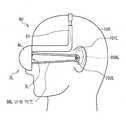
도 1은, 제1 실시예에 있어서의 이어 스피커 장치의 전체 구성을 나타낸 약선적(略線的) 사시도이다.Fig. 1 is a weak ship perspective view showing the overall configuration of an ear speaker device according to the first embodiment.
도 2는, 제1 실시예에 있어서의 이어 스피커 장치의 전체 구성을 나타낸 약선적 배면도이다.Fig. 2 is a weak ship rear view showing the overall configuration of the ear speaker device according to the first embodiment.
도 3은, 제1 실시예에 있어서의 이어 스피커 장치의 전체 구성을 나타낸 약선적 전면도(前面圖)이다.Fig. 3 is a weak ship front view showing the overall configuration of the ear speaker device according to the first embodiment.
도 4는, 제1 실시예에 있어서의 이어 스피커 장치의 장착 상태를 나타낸 약선적 측면도이다.4 is a weak ship side view showing a mounting state of the ear speaker device according to the first embodiment.
도 5는, 제1 실시예에 있어서의 이어 스피커 장치의 장착 상태를 나타낸 약선적 상단면도이다.Fig. 5 is a weak ship top view showing the mounting state of the ear speaker device according to the first embodiment.
도 6은, 일반적인 베이스 리플렉스형(bass reflex type)의 이어 스피커 장치를 나타낸 약선적 상단면도이다.Fig. 6 is a weak ship top view showing an ear speaker device of a general bass reflex type.
도 7은, 종래의 베이스 리플렉스형 스피커에 있어서의 주파수 특성을 나타낸 개략도이다.7 is a schematic diagram showing frequency characteristics in a conventional bass reflex speaker.
도 8은, 제1 실시예에 있어서의 이어 스피커 장치의 주파수 특성을 나타낸 개략도이다.Fig. 8 is a schematic diagram showing the frequency characteristics of the ear speaker device according to the first embodiment.
도 9는, 이론적인 주파수 특성을 나타낸 개략도이다.9 is a schematic diagram showing theoretical frequency characteristics.
도 10는, 실측에 의한 주파수 특성을 나타낸 개략도이다.10 is a schematic diagram showing frequency characteristics by actual measurement.
도 11은, 상하의 진폭 방향을 나타낸 개략도이다.Fig. 11 is a schematic diagram showing the up and down amplitude direction.
도 12는, 관형 덕트에 의한 저음역의 진폭 특성을 나타낸 특성 곡선도이다12 is a characteristic curve diagram showing amplitude characteristics of a low range by a tubular duct.
도 13은, 전후의 진폭 방향을 나타낸 개략도이다.Fig. 13 is a schematic diagram showing the amplitude direction before and after.
도 14는, 관형 덕트에 의한 저음역의 진폭 특성을 나타낸 특성 곡선도이다.Fig. 14 is a characteristic curve diagram showing amplitude characteristics of the low range by the tubular duct.
도 15는, 좌우의 진폭 방향을 나타낸 개략도이다.15 is a schematic diagram showing left and right amplitude directions.
도 16은, 관형 덕트에 의한 저음역의 진폭 특성을 나타낸 특성 곡선도이다.Fig. 16 is a characteristic curve diagram showing the amplitude characteristics of the low range by the tubular duct.
도 17은, 제1 실시예에 있어서의 이어 스피커 장치의 구성 및 장착의 예를 나타낸 약선적 측면도이다.17 is a weak ship side view showing an example of the configuration and mounting of an ear speaker device according to the first embodiment.
도 18은, 제1 실시예에 있어서의 이어 스피커 장치의 구성 및 장착의 예를 나타낸 약선적 측면도이다.18 is a weak ship side view showing an example of the configuration and mounting of an ear speaker device according to the first embodiment.
도 19는, 제1 실시예에 있어서의 이어 스피커 장치의 구성 및 장착의 예를 나타낸 약선적 측면도이다.19 is a weak ship side view showing an example of the configuration and mounting of the ear speaker device according to the first embodiment.
도 20은, 제1 실시예에 있어서의 이어 스피커 장치의 구성 및 장착의 예를 나타낸 약선적 측면도이다.20 is a weak ship side view showing an example of the configuration and mounting of the ear speaker device according to the first embodiment.
도 21은, 제1 실시예에 있어서의 이어 스피커 장치의 구성 및 장착의 예를 나타낸 약선적 측면도이다.Fig. 21 is a weak ship side view showing an example of the configuration and mounting of the ear speaker device according to the first embodiment.
도 22는, 제1 실시예에 있어서의 이어 스피커 장치의 구성 및 장착의 예를 나타낸 약선적 측면도이다.Fig. 22 is a weak ship side view showing an example of the configuration and mounting of the ear speaker device according to the first embodiment.
도 23은, 제1 실시예에 있어서의 이어 스피커 장치의 구성 및 장착의 예를 나타낸 약선적 측면도이다.23 is a weak ship side view showing an example of the configuration and mounting of the ear speaker device according to the first embodiment.
도 24는, 다른 실시예에 의한 관형 덕트의 구성예를 나타낸 약선적 사시도이다.24 is a weak ship perspective view showing an example of the configuration of a tubular duct according to another embodiment.
도 25는, 다른 실시예에 의한 관형 덕트의 구성예를 나타낸 약선적 사시도이다.25 is a weak ship perspective view showing an example of the configuration of a tubular duct according to another embodiment.
도 26은, 다른 실시예에 의한 관형 덕트의 구성예를 나타낸 약선적 사시도이다.26 is a weak ship perspective view showing an example of the configuration of a tubular duct according to another embodiment.
도 27은, 다른 실시예에 있어서의 이어 스피커 장치의 전체 구성을 나타낸 약선적 사시도이다.27 is a weak ship perspective view showing the overall configuration of an ear speaker device according to another embodiment.
도 28은, 다른 실시예에 있어서의 이어 스피커 장치의 전체 구성을 나타낸 약선적 사시도이다.28 is a weak ship perspective view showing the overall configuration of an ear speaker device according to another embodiment.
도 29는, 귀걸이 행거의 장착 상태를 나타낸 약선적 사시도이다.It is a weak ship perspective view which shows the attachment state of an earring hanger.
도 30은, 귀걸이 행거의 장착 상태를 나타낸 약선적 사시도이다.It is a weak ship perspective view which shows the attachment state of an earring hanger.
도 31은, 귀걸이 행거의 장착 상태를 나타낸 약선적 사시도이다.It is a weak ship perspective view which shows the attachment state of an earring hanger.
도 32는, 제2 실시예에 있어서의 이어 스피커 장치의 전체 구성을 나타낸 약선적 사시도이다.32 is a weak ship perspective view showing the overall configuration of an ear speaker device according to the second embodiment.
도 33은, 제2 실시예에 있어서의 이어 스피커 장치의 장착 상태를 나타낸 약 선적 측면도이다.Fig. 33 is a schematic side view showing the mounting state of the ear speaker device according to the second embodiment.
도 34는, 제2 실시예에 있어서의 이어 스피커 장치의 장착 상태를 나타낸 약선적 상단면도이다.Fig. 34 is a weak ship top view showing the mounting state of the ear speaker device according to the second embodiment.
도 35는, 제2 실시예에 있어서의 이어 스피커 장치의 구성 및 장착의 예를 나타낸 약선적 측면도이다.35 is a weak ship side view showing an example of the configuration and mounting of the ear speaker device according to the second embodiment.
도 36은, 제2 실시예에 있어서의 이어 스피커 장치의 구성 및 장착의 예를 나타낸 약선적 측면도이다.36 is a weak ship side view showing an example of the configuration and mounting of the ear speaker device according to the second embodiment.
도 37은, 제2 실시예에 있어서의 이어 스피커 장치의 구성 및 장착의 예를 나타낸 약선적 측면도이다.37 is a weak ship side view showing an example of the configuration and mounting of the ear speaker device according to the second embodiment.
도 38은, 제2 실시예에 있어서의 이어 스피커 장치의 구성 및 장착의 예를 나타낸 약선적 측면도이다.38 is a weak ship side view showing an example of the configuration and mounting of an ear speaker device according to the second embodiment.
도 39는, 제2 실시예에 있어서의 이어 스피커 장치의 구성 및 장착의 예를 나타낸 약선적 측면도이다.39 is a weak ship side view showing an example of the configuration and mounting of the ear speaker device according to the second embodiment.
도 40은, 제2 실시예에 있어서의 이어 스피커 장치의 구성 및 장착의 예를 나타낸 약선적 측면도이다.40 is a weak ship side view showing an example of the configuration and mounting of the ear speaker device according to the second embodiment.
도 41은, 제2 실시예에 있어서의 이어 스피커 장치의 구성 및 장착의 예를 나타낸 약선적 측면도이다.41 is a weak ship side view showing an example of the configuration and mounting of the ear speaker device according to the second embodiment.
도 42는, 다른 실시예에 의한 관형 덕트의 구성예를 나타낸 약선적 사시도이다.42 is a weak ship perspective view showing an example of the configuration of a tubular duct according to another embodiment.
도 43은, 다른 실시예에 의한 케이싱부의 구성예를 나타낸 약선적 단면도이 다.43 is a weak ship cross-sectional view showing a configuration example of a casing portion according to another embodiment.
도 44는, 다른 실시예에 의한 케이싱부의 구성예를 나타낸 약선적 단면도이다.44 is a weak ship cross-sectional view showing a configuration example of a casing portion according to another embodiment.
도 45는, 다른 실시예에 의한 케이싱부의 구성예를 나타낸 약선적 단면도이다.45 is a weak ship cross-sectional view showing a configuration example of a casing portion according to another embodiment.
도 46은, 다른 실시예에 의한 관형 덕트의 구성을 나타낸 약선적 사시도이다.46 is a weak ship perspective view showing the structure of a tubular duct according to another embodiment.
도 47은, 다른 실시예에 의한 관형 덕트의 구성을 나타낸 약선적 사시도이다.47 is a weak ship perspective view showing the structure of a tubular duct according to another embodiment.
도 48은, 다른 실시예에 의한 관형 덕트의 구성을 나타낸 약선적 사시도이다.48 is a weak ship perspective view showing the structure of a tubular duct according to another embodiment.
[도면의 주요 부분에 대한 부호의 설명][Description of Symbols for Main Parts of Drawing]
(1, 20, 30, 40, 50, 60, 70, 80, 90, 200, 220, 230, 240, 250, 260, 270, 280, 290, 900) 스피커 장치,(1, 20, 30, 40, 50, 60, 70, 80, 90, 200, 220, 230, 240, 250, 260, 270, 280, 290, 900) speaker unit,
(2L, 2R, 72L, 92L, 202L, 202R, 902L, 902R) 전기 음향 변환부,(2L, 2R, 72L, 92L, 202L, 202R, 902L, 902R) electro-acoustic converter,
(3, 31, 51, 61, 71, 81) 밴드부,(3, 31, 51, 61, 71, 81) band part,
(4L, 4L1, 4L3, 4R, 204L, 204R, 304L, 404L, 504L, 604L, 704L, 804L, 9O4L, 904R) 케이싱부,(4L, 4L1, 4L3, 4R, 204L, 204R, 304L, 404L, 504L, 604L, 704L, 804L, 9O4L, 904R) Casing part,
(7L, 7R, 207L, 207R, 907L, 907R) 스피커 유닛,(7L, 7R, 207L, 207R, 907L, 907R) speaker unit,
(8L, 8R, 208L, 208R, 261L, 281L, 298L, 308L, 608L, 708L, 808L, 908L, 908R) 관형 덕트,(8L, 8R, 208L, 208R, 261L, 281L, 298L, 308L, 608L, 708L, 808L, 908L, 908R) tubular duct,
(8AL, 8AR, 208AL, 208AR, 908AL, 908AR) 구멍부,(8AL, 8AR, 208AL, 208AR, 908AL, 908AR) hole
(100) 두부, (101L) 귓바퀴, (102L) 외이도 입구,(100) tofu, (101L) auricle, (102L) ear canal entrance,
(103L) 고막, (901L, 901R) 행거, (910)~(913) 나사(103L) tympanic membrane, (901L, 901R) hanger, (910)-(913) screw
이하, 도면을 참조하여, 본 발명의 일실시예를, 제1 실시예와 제2 실시예로 나누어 상세하게 설명한다.EMBODIMENT OF THE INVENTION Hereinafter, with reference to drawings, one Embodiment of this invention is described in detail dividing into 1st Example and 2nd Example.
(1) 제1 실시예(1) First embodiment
(1-1) 이어 스피커 장치의 구성(1-1) Configuration of Ear Speaker Unit
도 1, 도 2 및 도 3에 있어서, (1)은 전체적으로 제1 실시예에 있어서의 이어 스피커 장치를 나타내고, 휴대용 CD(Compact Disc) 플레이어나 DMP(Digital Music player)의 재생 처리 등에 의해 생성된 오디오 신호를 재생음으로 변환하여, 이것을 리스너가 청취하게 하도록 되어 있다.In Fig. 1, Fig. 2 and Fig. 3,
이어(ear) 스피커 장치(1)는, 일반적인 상자형의 스피커 장치와는 상이하고, 헤드폰 장치와 마찬가지로 리스너의 두부에 장착되는 것을 전제로 하고 있고, 크게 나누어 오디오 신호를 재생음으로 변환하는 전기 음향 변환부(2L, 2R)와, 상기 전기 음향 변환부(2L, 2R)를 리스너의 두부에 장착하여 고정시키기 위한 밴드부(3)에 의해 구성되어 있다.The
전기 음향 변환부(2L, 2R)는, 구체(球體)가 수직 방향으로 4등분된 것과 같은 형상으로 이루어지는 케이싱부(4L, 4R)를 중심으로 구성되어 있다. 케이싱 부(4L, 4R)는, 각각 후면측 및 좌우 내측에 평면 부분이 형성되어 있고, 좌우 내측에는 리스너의 두부에 대한 측압(側壓)을 완화시키기 위한 패드부(5L, 5R)가 장착되어 있다.The
케이싱부(4L, 4R)의 후면 측에 있어서의 평면 부분인 배플판(4AL, 4AR)에는, 오디오 신호를 재생음으로 변환하는 스피커 유닛(7L, 7R)이 장착되어 있다. 이 스피커 유닛(7L, 7R)은, 휴대용 CD 플레이어나 DMP 등으로부터 접속 케이블(6)에 의해 공급되는 오디오 신호에 따라 진동판을 진동시킴으로써 방음하도록 되어 있다.The
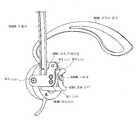
또한, 케이싱부(4L, 4R)의 배플판(4AL, 4AR)에는, 소정의 경도를 가지는 알루미늄 등의 금속 또는 소정의 경도를 가지는 플라스틱이나 수지 등으로 이루어지고, 소정 굵기를 가지는 중공(中空)의 부재가 측면이 대략 U자형으로 절곡된 관형 덕트(8L, 8R)가 장착되어 있다. 이 관형 덕트(8L, 8R)는, 도 1에 나타낸 바와 같이, 외단부가 각각 좌우 내측 방향으로 굽혀져 있고, 또한 뒤쪽 선단부의 대략 중앙에 각각 구멍부(8AL, 8AR)가 형성되어 있다.Further, the baffle plates 4AL and 4AR of the
밴드부(3)는, 중앙부(3A)를 중심으로 일반적인 인간의 두부의 형상에 맞추어, 위쪽이 볼록한 대략 아치형으로 형성되어 있는 동시에, 상기 중앙부(3A)에 대하여 신축 가능하게 슬라이드 이동할 수 있는 조절부(3BL, 3BR)에 의해 밴드부(3) 전체의 길이를 조정할 수 있도록 되어 있다.The band portion 3 is formed in a generally arcuate shape with a convex upper side in accordance with the shape of a general human head around the center portion 3A, and at the same time, an adjustment portion that can be elastically slidably moved with respect to the center portion 3A ( The length of the whole band part 3 can be adjusted with 3BL and 3BR.
또한, 밴드부(3)는, 일반적인 인간의 두부의 형상보다 작은 직경의 아치형으로 형성되어 있는 동시에 탄성력을 가지고 있고, 리스너에 장착될 때 케이싱부(4L, 4R)를 좌우로 넓히면서 장착되면, 장착 후에 상기 탄성력의 작용에 의해 원래의 형 상으로 돌아오려고 하므로, 케이싱부(4L, 4R)를 상기 리스너의 두부에 대하여 맞닿게 한 상태로 유지시키도록 되어 있다.In addition, the band portion 3 is formed in an arcuate shape having a diameter smaller than that of a general human head, and has elastic force, and when the band portion 3 is mounted while widening the
그리고, 이어 스피커 장치(1)는, 도 1~도 3에 나타낸 바와 같이 대략 좌우 대칭으로 구성되어 있으므로, 이하에서는 주로 좌측의 전기 음향 변환부(2L)를 예로 들어 설명한다.Then, since the
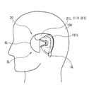
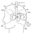
실제로, 이어 스피커 장치(1)는, 도 4의 좌측면도에 나타낸 바와 같이, 밴드부(3)에 있어서의 길이가 조정된 후 리스너의 두부(100)에 장착됨으로써, 조절부(3BL)의 하단 측에 장착된 전기 음향 변환부(2L)를 리스너의 두부에 있어서의 귓바퀴(101L)보다 약간 전방에 위치시키도록 되어 있다.In fact, the
이로써, 이어 스피커 장치(1)의 전기 음향 변환부(2L)는, 스피커 유닛(7L)으로부터 방사된 중고음을 직접 리스너의 외이도 내부에 도달시키는 동시에, 상기 리스너의 볼부분이나 귓바퀴(101L) 등으로 반사된 반사음도 외이도 내부에 도달하게 할 수 있으므로, 일반적인 거치형 스피커를 통하여 청취한 경우와 마찬가지의, 자연스러운 음상 정위를 줄 수 있도록 되어 있다.As a result, the
이 때, 이어 스피커 장치(1)는, 리스너에 대하여 정상적으로 장착되었을 때, 스피커 유닛(7L)이 귓바퀴(101L) 및 외이도 입구(102L)의 약간 전방에 위치하고, 관형 덕트(8L)의 구멍부(8AL)가 외이도 입구(102L)의 근방에 위치하도록 되어 있다.At this time, when the
또한, 관형 덕트(8L)는, 그 선단이 대략 U자형으로 형성되어 있으므로, 리스너의 외이도 입구(102L)에 맞닿을 뿐 외이도 내로 침입하지 않도록 되어 있다. 이 로써, 이어 스피커 장치(1)는, 상기 리스너가 이어 스피커 장치(1)의 장착시 등에, 잘못하여 관형 덕트(8L)에 의해 상기 외이도 내를 손상시켜 버리는 것을 미연에 방지할 수 있도록 되어 있다.In addition, since the tip of the
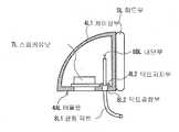
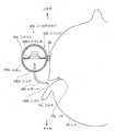
여기서, 도 4에 있어서의 Q1-Q2 단면을 도 5에 나타낸 바와 같이, 케이싱부(4L)는 스피커 유닛(7L)이 장착된 상태로 관형 덕트(8L)를 제외하고 밀폐된 공간을 형성하고 있고, 스피커 유닛(7L)에 대하여 케이싱부(4L) 및 상기 관형 덕트(8L)에 의해 공진 회로를 형성하도록 되어 있다.Here, as shown in FIG. 5, the Q1-Q2 cross section in FIG. 4, the
또한, 관형 덕트(8L)는, 케이싱부(4L)의 내부로부터 케이싱부(4L)의 배플판(4AL)을 관통하여 리스너의 외이도 입구(102L)의 근방에 도달하고 있다. 실제로, 전기 음향 변환부(2L)는, 관형 덕트(8L)를 베이스 리플렉스 덕트로서 작용시킴으로써, 전체적으로 베이스 리플렉스형의 스피커로서 동작하도록 되어 있다.The
그런데, 일반적인 베이스 리플렉스형 스피커에서는, 덕트가 케이싱의 내부에만 설치되고, 외부로는 연장되지 않도록 되어 있다. 그래서, 전기 음향 변환부(2L)와의 비교용으로, 도 5의 대응 부분에 동일 부호를 부여한 도 6에 나타낸 바와 같은 전기 음향 변환부(12L)를 상정한다.By the way, in the general bass reflex type speaker, the duct is provided only inside the casing and does not extend to the outside. Therefore, for the comparison with the
상기 전기 음향 변환부(12L)(도 6)는, 일반적인 베이스 리플렉스형 스피커와 마찬가지로 구성되어 있고, 전기 음향 변환부(2L)의 관형 덕트(8L)(도 5)에 대신하여, 케이싱부(4L)의 내측에만 2개의 관형 덕트(18L, 19L)를 가지고 있다.The said electroacoustic conversion part 12L (FIG. 6) is comprised similarly to a general bass reflex type speaker, and replaces the
상기 전기 음향 변환부(12L)의 경우, 스피커 유닛(7L)의 위치를 가상적인 음원(音源)의 위치(이하, 이것을 가상 음원 위치라고 함) PM이라고 보았을 때의, 상 기 스피커 유닛(7L)으로부터 방사된 중고음이 리스너의 고막(103L)에 도달할 때까지의 경로 길이 EM과, 구멍부(18AL, 19AL)를 가상 음원 위치 PL2라고 보았을 때의, 관형 덕트(18L) 내 및 (19L) 내를 전해져 상기 구멍부(18AL, 19AL)로부터 방사된 저음이 리스너의 고막(103L)에 도달할 때까지의 경로 길이 EL2를 비교하면, 경로 길이 EM≒경로 길이 EL2로 되어 있다.In the case of the electro-acoustic conversion unit 12L, the
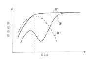
여기서, 전기 음향 변환부(12L)에 의해 고막(103L)에 도달하는 음의 주파수 특성을 도 7에 나타낸다. 이 도 7에 나타낸 바와 같이, 일반적인 베이스 리플렉스형의 전기 음향 변환부(12L)는, 스피커 유닛(7L)으로부터 방사되는, 특성 곡선 SM으로 나타낸 바와 같은 주파수 특성으로 되는 중고음(中高音)과, 관형 덕트(18L) 내 및 (19L) 내를 전해져 구멍부(18AL, 19AL)로부터 방사되는, 특성 곡선 SL2로 나타낸 바와 같은 주파수 특성으로 되는 저음을 맞추어 리스너의 고막(103L)까지 도달시키게 된다.Here, FIG. 7 shows the frequency characteristics of sound reaching the tympanic membrane 103L by the electroacoustic converter 12L. As shown in Fig. 7, the general bass reflex type electro-acoustic converter 12L has a mid-tone with a frequency characteristic as indicated by the characteristic curve SM radiated from the
이로써, 전기 음향 변환부(12L)는, 특성 곡선 SM 및 특성 곡선 SL2가 합성된 특성 곡선 SG2에 나타낸 바와 같이, 특성 곡선 SM에 있어서의 저음역의 음압 레벨이 어느 정도 상승된 재생음을 리스너가 청취할 수 있다.Thereby, the electroacoustic converter 12L can listen to the reproduction sound of which the sound pressure level of the low range in the characteristic curve SM is raised to some extent as shown in the characteristic curve SG2 in which the characteristic curve SM and the characteristic curve SL2 are synthesized. Can be.
한편, 본 발명에 의한 전기 음향 변환부(2L)(도 5)에서는, 스피커 유닛(7L)을 가상 음원 위치 PM이라고 간주했을 때의, 상기 스피커 유닛(7L)으로부터 방사된 중고음이 리스너의 고막(103L)에 도달할 때까지의 경로 길이 EM과, 구멍부(8AL)를 가상 음원 위치 PL1이라고 보았을 때의, 관형 덕트(8L) 내를 전해져 상기 구멍부(8AL)로부터 방사된 저음이 리스너의 고막(103L)에 도달할 때까지의 경로 길이 EL1을 비교하면, 경로 길이 EM > 경로 길이 EL1으로 되어 있다.On the other hand, in the
여기서, 전기 음향 변환부(2L)에 의해 고막(103L)에 도달하는 음의 주파수 특성을 도 8에 나타낸다. 전기 음향 변환부(2L)는, 전술한 바와 같이 베이스 리플렉스형 스피커의 일종이므로, 도 7에 나타낸 경우와 마찬가지로, 스피커 유닛(7L)으로부터 방사되는, 특성 곡선 SM으로 나타낸 바와 같은 주파수 특성으로 되는 중고음과, 관형 덕트(8L)를 전해져 구멍부(8AL)로부터 방사되는, 특성 곡선 SL1으로 나타낸 바와 같은 주파수 특성으로 되는 저음을 맞추어 리스너의 고막(103L)까지 도달시키게 된다.Here, FIG. 8 shows the frequency characteristics of the sound reaching the tympanic membrane 103L by the
그런데, 일반적으로 음원으로부터의 거리와 음압 레벨은 반비례의 관계에 있다. 여기서 전기 음향 변환부(2L)(도 5)와 전기 음향 변환부(12L)(도 6)의 경로 길이를 비교하면, 경로 길이 EL1 < 경로 길이 EL2의 관계로 된다.However, in general, the distance from the sound source and the sound pressure level are inversely related. When the path lengths of the
즉, 전기 음향 변환부(2L)(도 5)는, 가상 음원 위치 PL1이 전기 음향 변환부(12L)(도 6)의 가상 음원 위치 PL2보다 리스너의 외이도 입구(102L) 근방에 위치하고 있으므로, 관형 덕트(8L) 내를 전해져 구멍부(8AL)(가상 음원 위치 PL1)로부터 방사되는 저음을, 전기 음향 변환부(12L)의 경우보다 높은 음압 레벨로 고막(103L)까지 도달하게 할 수 있도록 되어 있다.That is, in the
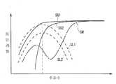
즉, 2개의 특성 곡선 SL1 및 SL2를 중첩한 도 9에 나타낸 바와 같이, 관형 덕트(8L)에 의한 저음의 특성 곡선 SL1은, 경로 길이 EL1 < 경로 길이 EL2의 관계에 의해, 관형 덕트(18L, 19L)에 의한 저음의 특성 곡선 SL2와 비교하여 전체적인 음압 레벨이 높아진다.That is, as shown in FIG. 9 in which two characteristic curves SL1 and SL2 are superimposed, the characteristic curve SL1 of the bass by the
이 결과, 제1 실시예에 있어서의 전기 음향 변환부(2L)는, 특성 곡선 SM 및 특성 곡선 SL1이 합성된 특성 곡선 SG1으로 나타낸 바와 같이, 특성 곡선 SM에 있어서의 저음역의 음압 레벨이 전기 음향 변환부(12L)의 경우(특성 곡선 SG2)보다 상승된, 비교적 낮은 주파수대까지 충분한 음압 레벨의 재생음을 리스너가 청취할 수 있도록 되어 있다.As a result, the
여기서, 특성 곡선 SG1과 특성 곡선 SG2를 비교하면, 특성 곡선 SG2에서는 저음역 측으로 진행하는데 따라 비교적 급준하게 음압 레벨이 저하되어 있는 것에 대해, 특성 곡선 SG1에서는 저음역 측으로 진행하는데 따라 음압 레벨의 저하 정도가 완만하게 되어 있는 것을 알 수 있다.Here, when the characteristic curve SG1 and the characteristic curve SG2 are compared, in the characteristic curve SG2, while the sound pressure level decreases relatively steeply as it progresses to the low range side, in the characteristic curve SG1, the degree of deterioration of the sound pressure level decreases as it progresses to the low range side. I can see that it is supposed to be done.
즉, 전기 음향 변환부(2L)는, 전기 음향 변환부(12L)와 비교하여, 넓은 주파수 대역에 걸쳐 높은 음압 레벨로 되는, 즉 충분한 저음역이 포함되는 양호한 재생음을 리스너의 고막(103)에 전달하여 청취할 수 있도록 되어 있다.That is, compared with the electroacoustic converter 12L, the
이 경우, 전기 음향 변환부(2L)는, 도 4 및 도 5에 나타낸 바와 같이, 리스너의 외이도 입구(102L)의 근방에 관형 덕트(8L)의 선단부를 맞닿게 할 뿐, 상기 외이도 입구(102L)를 완전하게는 폐색하지 않는다.In this case, as shown in FIGS. 4 and 5, the
그러므로, 전기 음향 변환부(2L)는, 스피커 유닛(7L)으로부터 방사되는 중고음 및 관형 덕트(8L)의 구멍부(8AL)로부터 방사되는 저음을 맞춘 재생음에 더하여, 리스너의 주위에서 발생한 음(이하 이것을 주위음이라고 함)을 차단하지 않고 상기 리스너의 고막(103L)까지 도달시켜 청취할 수 있도록 되어 있다.Therefore, the electro-
또한, 전기 음향 변환부(2L)는, 케이싱부(4L)의 내용적이 10[ml], 스피커 유 닛(7L)의 외경이 21[mm], 상기 스피커 유닛(7L)의 진동판에 있어서의 유효 진동 반경이 8.5[mm], 진동계의 등가(等價) 질량이 0.2[g], 최저 공진 주파수 f0가 360[Hz], 공진의 Q0가 1.0으로 되어 있다.Moreover, 2 L of electroacoustic conversion parts are effective in the diaphragm of the said
또한, 관형 덕트(8L)는, 내경이 1.8[mm], 상기 관형 덕트(8L)의 케이싱부(4L) 내에 위치하는 내부단(內部端)(8BL)으로부터 구멍부(8AL)까지의 유효 길이가 50[mm], 배플판(4AL)의 표면으로부터 구멍부(8AL)까지의 거리가 약 35[mm]로 되어 있다.The
여기서, 관형 덕트(8L)는, 그 측면이 U자형으로 형성되고, 외단부의 중앙에 구멍부(8AL)가 형성되어 있으므로, 실질적으로 상반분 및 하반분에 의한 2개의 베이스 리플렉스 덕트를 구성하고 있는 것과 같고, 상기 관형 덕트(8L)를 1개의 관형 덕트로 환산한 경우의 내경(이 경우에는 약 2.5[mm]에 상당함)이 고려된 후, 그 내경 및 유효 길이가 결정되어 있다.Here, the
즉, 관형 덕트(8L)는, 측면이 U자형으로 형성된 것에 의해, 1개의 관형 덕트로 한 경우에 비해 그 유효 길이를 짧게 설정할 수 있는 동시에, 디자인성 및 안전성을 크게 향상시킬 수 있도록 되어 있다.That is, the
상기 전기 음향 변환부(2L)(도 5) 및 전기 음향 변환부(12L)(도 6)에 대하여, 인간의 귓바퀴 및 외이도를 모방한 측정용 지그를 사용하여 실제의 주파수 특성을 측정한 바, 도 10에 나타낸 바와 같은 특성 곡선 SGl1(전기 음향 변환부(2L)의 경우) 및 특성 곡선 SG12(전기 음향 변환부(12L)의 경우)를 얻을 수 있었다.Actual frequency characteristics of the
이 도 10에서는, 도 9에 나타낸 이론적인 주파수 특성과 마찬가지로, 대략 500[Hz] 이하의 저음역에 있어서, 전기 음향 변환부(2L)의 특성 곡선 SG11이 전기 음향 변환부(12L)의 특성 곡선 SG12보다 높은 음압 레벨로 되어 있다. 즉, 실제로 전기 음향 변환부(2L)가 리스너에 대하여 충분한 저음을 포함하는 양호한 재생음을 청취하게 할 수 있는 것이 나타나 있다.In this FIG. 10, similar to the theoretical frequency characteristic shown in FIG. 9, in the low range of approximately 500 [Hz] or less, the characteristic curve SG11 of the
그리고, 전기 음향 변환부(2L)에서는, 소정의 경도를 가지는 알루미늄 등의 금속 또는 소정의 경도를 가지는 플라스틱이나 수지 등에 의해 관형 덕트(8L)를 형성하고, 그 관형 덕트(8L)의 선단부가 외이도 입구(102L)의 근방에 맞닿아 있으므로, 관형 덕트(8L)의 선단부에 생긴 저역의 진동 성분을, 주로 피부를 통한 전도(傳導)에 의해 리스너의 고막(103L)에까지 도달시켜 청취하게 할 수 있도록 되어 있다.In the
특히, 저음감은, 관형 덕트(8L)가 외이도 입구(102L)의 근방에 맞닿아 있으므로, 관형 덕트(8L)의 선단부에 생긴 저역의 진동에 의해 인간의 피부가 떨려 그것이 피부의 신경으로부터 뇌에 전해지는 것으로 사용자에 체감되는 것이다.In particular, since the
이것은, 도 11에 나타낸 바와 같이, 관형 덕트(8L)의 선단부분에 있어서의 상하 방향(굵은 화살표)의 진폭량을 측정한 결과에 나타나 있다. 도 12에 나타낸 바와 같이, 알루미늄 등의 하드한 금속으로 이루어지는 관형 덕트(8L)의 선단부분에 생기는 상하 방향(굵은 화살표)의 진동 즉 상하 방향의 진폭량으로서는, 특히 약 100[Hz] 이하로 매우 큰 것을 알 수 있다.This is shown in the result of having measured the amplitude amount of the up-down direction (thick arrow) in the front-end | tip part of 8 L of tubular ducts, as shown in FIG. As shown in Fig. 12, the vibration amount in the vertical direction (thick arrow) generated at the tip of the
또한, 도 13에 나타낸 바와 같이, 관형 덕트(8L)의 선단부분에 있어서의 전후 방향(굵은 화살표)의 진폭량을 측정한 결과, 도 14에 나타낸 바와 같이, 알루미 늄 등의 하드한 금속으로 이루어지는 관형 덕트(8L)의 선단부분에 생기는 전후 방향의 진동 즉 전후 방향의 진폭량으로서도, 특히 약 100[Hz] 이하로 매우 큰 것을 알 수 있다.In addition, as shown in FIG. 13, the amplitude amount of the front-back direction (thick arrow) in the front-end | tip part of 8 L of tubular ducts was measured, As shown in FIG. 14, it consists of hard metals, such as aluminum, It can be seen that the vibration in the front-back direction, that is, the amplitude in the front-back direction, which occurs at the tip of the
또한, 도 15에 나타낸 바와 같이, 관형 덕트(8L)의 선단부분에 있어서의 좌우 방향(굵은 화살표)의 진폭량을 측정한 결과, 도 16에 나타낸 바와 같이, 알루미늄 등의 하드한 금속으로 이루어지는 관형 덕트(8L)의 선단부분에 생기는 좌우 방향의 진동 즉 좌우 방향의 진폭량으로서도, 특히 약 100[Hz] 이하로 매우 큰 것을 알 수 있다.As shown in FIG. 15, the amplitude of the left and right directions (thick arrows) at the tip of the
한편, 일래스터머 등의 부드러운 소재에 의해 형성된 관형 덕트(도시하지 않음)가 이어 스피커 장치(1)에 사용되고 있었던 경우, 그 관형 덕트가 외이도 입구(102L)의 근방에 맞닿아 있었다고 해도, 부드러운 소재이므로 관형 덕트의 선단에 생기는 진동이 리스너의 피부를 통하여 전해지지 않고, 특히 약 100[Hz] 이하의 저음의 음압을 관형 덕트의 선단부에 생기는 진동에 의해 올리는 것은 어렵다.On the other hand, when a tubular duct (not shown) formed of a soft material such as elastomer is used for the
단, 이어 스피커 장치(1)에서는, 관형 덕트(8L)의 베이스 리플렉스 덕트로서의 작용에 의해, 약 100[Hz] 이하의 저음에 대해서도 그 음압 레벨이 어느 정도 올려지고 있으므로, 크게 문제되지는 않는다.However, in the
이와 같이, 이어 스피커 장치(1)에서는, 관형 덕트(8L)의 선단부분에 대하여 상하 방향, 전후 방향 및 좌우 방향으로의 진동이 크게 발생하고, 이것이 리스너의 피부를 통한 전도에 의해 리스너의 고막(103L)에까지 도달하게 되므로, 충분한 레벨의 저음을 리스너가 청취할 수 있도록 되어 있다.As described above, in the
이와 같이, 이어 스피커 장치(1)는, 리스너의 두부(100)에 장착되었을 때, 스피커 유닛(7L)을 리스너의 외이도 입구(102L)로부터 약간 이격된 장소에 위치시키고, 그 스피커 유닛(7L)으로부터 재생음의 중고음을 방사하는 동시에, 케이싱부(4L)로부터 상기 외이도 입구(102L)의 근방까지 연장되고 베이스 리플렉스 덕트로서 작용하는 관형 덕트(8L)의 구멍부(8AL)로부터 재생음의 저음을 방사하고, 또한 관형 덕트(8L)의 주로 피부 전도 작용에 의해서도 그 저음을 리스너에 전달함으로써, 자연스러운 음상 정위를 주면서 충분한 저음을 포함하는 양호한 재생음을 상기 리스너가 청취할 수 있도록 되어 있다.Thus, when the
(1-2) 다른 이어 스피커 장치의 구성예(1-2) Configuration example of another ear speaker device
그런데, 제1 실시예에 있어서의 이어 스피커 장치(1)는, 도 1~ 도 4에 나타낸 바와 같이, 장착부로서의 밴드부(3)에 의해 전기 음향 변환부(2L, 2R)를 리스너의 두부(100)에 장착하도록 되어 있지만, 이 밴드부(3)에 대신하여 다른 각종의 장착부를 사용함으로써 전기 음향 변환부(2L, 2R)를 리스너의 두부(100)에 장착하도록 해도 된다.By the way, in the
그리고, 이하에서는, 전술한 이어 스피커 장치(1)의 경우와 마찬가지로, 주로 좌측의 전기 음향 변환부(2L)를 예로 들어 설명하지만, 우측의 전기 음향 변환부(2R)에 대하여는, 상기 좌측의 전기 음향 변환부(2L)와 좌우 대칭으로 구성되어 있는 것으로 한다.In the following, similarly to the case of the
예를 들면, 도 17에 나타낸 이어 스피커 장치(20)는, 이른바 이어 클립형으로서 구성되어 있고, 이어 스피커 장치(1)(도 1~도 4)에 있어서의 밴드부(3)에 대 신하여, 리스너의 귓바퀴(101L)에 걸기 위한 이어 클립(21L)이 전기 음향 변환부(2L)의 케이싱부(4L)에 장착되어 있다.For example, the
상기 이어 스피커 장치(20)는, 이어 클립(21L)이 리스너의 귓바퀴(101L)에 걸림으로써 전기 음향 변환부(2L)를 리스너의 두부(100)에 장착할 수 있고, 이어 스피커 장치(1)와 마찬가지로, 자연스러운 음상 정위를 주면서 충분한 저음을 포함하는 양호한 재생음을 상기 리스너가 청취할 수 있도록 되어 있다.In the
또한, 도 18에 나타낸 이어 스피커 장치(30)는, 이른바 언더친형(under-chin type)으로서 구성되어 있고, 이어 스피커 장치(1)(도 1~도 4)에 있어서의 밴드부(3)에 대신하여, 좌우의 전기 음향 변환부(2L, 2R)를 접속하는 동시에 리스너의 귓바퀴(101L)에 걸기 위한 밴드부(31)가 케이싱부(4L)에 장착되어 있다. 이 밴드부(31)의 중앙부(31A)는, 아래로 오목한 대략 아치형으로 형성되고, 리스너의 턱아래를 통하여 좌우로 걸쳐지는 것을 전제로 하고 있다.Moreover, the
상기 이어 스피커 장치(30)(도 18)는, 밴드부(31)의 귀걸이부(31BL)가 리스너의 귓바퀴(101L)에 걸림으로써 전기 음향 변환부(2L)를 리스너의 두부(100)에 장착할 수 있고, 이어 스피커 장치(1)와 마찬가지로, 자연스러운 음상 정위를 주면서 충분한 저음을 포함하는 양호한 재생음을 상기 리스너가 청취할 수 있도록 되어 있다.In the ear speaker device 30 (FIG. 18), the earring part 31BL of the band part 31 is engaged with the
또한, 도 19에 나타낸 이어 스피커 장치(40)는, 이른바 숄더 홀드형으로서 구성되어 있고, 이어 스피커 장치(1)(도 1~도 4)에 있어서의 밴드부(3)에 대신하여, 좌우의 전기 음향 변환부(2L, 2R)를 접속하는 동시에 리스너의 견부(肩部)로부 터 지지하는 숄더 암(41)이 케이싱부(4L)에 장착되어 있다. 이 숄더 암(41)의 중앙부(41A)는, 뒤쪽으로 볼록한 대략 아치형으로 형성되고, 리스너의 목 뒤로부터 어깨의 상부에 걸어 좌우에 걸쳐지는 것을 전제로 하고 있다.In addition, the
상기 이어 스피커 장치(40)(도 19)는, 리스너의 양 어깨에 걸쳐 걸림으로써 전기 음향 변환부(2L)를 리스너의 두부(100)에 장착할 수 있고, 이어 스피커 장치(1)와 마찬가지로, 자연스러운 음상 정위를 주면서 충분한 저음을 포함하는 양호한 재생음을 상기 리스너가 청취할 수 있도록 되어 있다.The ear speaker device 40 (FIG. 19) can be attached to the
또한, 도 20에 나타낸 이어 스피커 장치(50)는, 이른바 넥 밴드형으로서 구성되어 있고, 이어 스피커 장치(1)(도 1~도 4)에 있어서의 밴드부(3)에 대신하여, 좌우의 전기 음향 변환부(2L, 2R)를 접속하는 동시에 리스너의 귓바퀴(101L)에 걸기 위한 밴드부(51)가 케이싱부(4L)에 장착되어 있다. 이 밴드부(51)의 중앙부(51A)는, 뒤쪽으로 볼록한 대략 아치형으로 형성되고, 리스너의 후두부의 뒤쪽에서 걸쳐지는 것을 전제로 하고 있다.In addition, the
상기 이어 스피커 장치(50)(도 20)는, 밴드부(51)의 귀걸이부(51BL)가 리스너의 귓바퀴(101L)에 걸림으로써 전기 음향 변환부(2L)를 리스너의 두부(100)에 장착할 수 있고, 이어 스피커 장치(1)와 마찬가지로, 자연스러운 음상 정위를 주면서 충분한 저음을 포함하는 양호한 재생음을 상기 리스너가 청취할 수 있도록 되어 있다.The ear speaker device 50 (FIG. 20) is such that the earring portion 51BL of the band portion 51 is engaged with the
또한, 도 21에 나타낸 이어 스피커 장치(60)는, 도 20에 나타낸 이어 스피커 장치(50)에 있어서의 전기 음향 변환부(2L)를 리스너의 귓바퀴(101)보다 후방에 위 치시키는 동시에, 관형 덕트(8L)에 대신하여 대략 L자형으로 이루어지는 관형 덕트(68L)가 리스너의 귓바퀴(101L)의 후방에 위치하는 케이싱부(4L)로부터 외이도 입구(102L) 근방까지 연장되어 있다. 또한, 좌우의 전기 음향 변환부(2L, 2R)는, 리스너의 목 뒤쪽에서 걸쳐지는 밴드부(61)에 의해 접속되어 있다.In addition, the
상기 이어 스피커 장치(60)(도 21)는, 관형 덕트(68L)가 리스너의 귓바퀴(101L)에 걸림으로써 전기 음향 변환부(2L)를 리스너의 헤드부(100)에 장착할 수 있고, 이어 스피커 장치(1)와 마찬가지로, 자연스러운 음상 정위를 주면서 충분한 저음을 포함하는 양호한 재생음을 상기 리스너가 청취할 수 있도록 되어 있다.In the ear speaker device 60 (FIG. 21), the tubular duct 68L is engaged with the
또한, 도 22에 나타낸 이어 스피커 장치(70)는, 전기 음향 변환부(2L)에 더하여, 전술한 전기 음향 변환부(12L)(도 6)와 동일한 구성으로 이루어지는 후방 전기 음향 변환부(72L)를 가지고 있고, 이어 스피커 장치(1)(도 1~도 4)에 있어서의 밴드부(3)에 대신하는 밴드부(71)에 의해, 전기 음향 변환부(2L)를 귓바퀴(101L)의 전방에 위치시키는 동시에, 후방 전기 음향 변환부(72L)를 상기 귓바퀴(101L)의 후방에 위치시키도록 되어 있다.In addition, the
또한, 후방 전기 음향 변환부(72L)에는, 4채널이나 5.1채널 등의 멀티 채널 음원에 있어서의 리어 채널용의 음성 신호가 공급되도록 되어 있다.The rear
상기 이어 스피커 장치(70)(도 22)는, 리스너의 두부(100)에 장착됨으로써, 전기 음향 변환부(2L) 및 후방 전기 음향 변환부(72L)를 상기 리스너의 두부(100)에 장착할 수 있고, 전기 음향 변환부(2L) 및 후방 전기 음향 변환부(72L) 사이에 귓바퀴(101L)를 끼워넣은 상태에서, 자연스러운 음상 정위를 주면서, 충분한 저음 을 포함하는 양호한 재생음(환경음)을 상기 리스너가 청취할 수 있도록 되어 있다.The ear speaker device 70 (FIG. 22) is mounted to the
또한, 이 경우, 이어 스피커 장치(70)(도 22)에서는, 밴드부(71)에 가진기(加振器)(75)를 장착하고, 예를 들면, 5.1채널 음원에 있어서의 중저음 성분에 따른 진동을 리스너의 두부(100)에 가하도록 해도 된다.In this case, the ear speaker device 70 (FIG. 22) is equipped with an exciter 75 in the
그리고, 이어 스피커 장치(70)(도 22)는, 전기 음향 변환부(2L)로부터 관형 덕트(8L)를 리스너의 외이도 입구(102L) 근방까지 연장하는 것 외에도, 이어 스피커 장치(60)(도 21)와 마찬가지로, 후방용 전기 음향 변환부(72L)로부터 관형 덕트를 리스너의 외이도 입구(102L) 근방까지 연장하도록 하거나, 또는 전기 음향 변환부(2L) 및 후방용 전기 음향 변환부(72L)의 양쪽으로부터 관형 덕트를 리스너의 외이도 입구(102L) 근방까지 연장하도록 해도 된다.The ear speaker device 70 (FIG. 22) extends the
또한, 도 23에 나타낸 이어 스피커 장치(80)는, 이어 스피커 장치(1)(도 1~도 4)에 있어서의 밴드부(3)에 대신하여, 좌우의 전기 음향 변환부(2L, 2R)를 접속하는 동시에 리스너의 볼부분보다 앞쪽에 위치시키기 위한 밴드부(81)가 케이싱부(4L)에 장착되어 있다.In addition, the
또한, 케이싱부(4L)에는, 관형 덕트(8L)에 대신하여 케이싱부(4L)로부터 리스너의 외이도 입구(102L) 근방까지 연장된 관형 덕트(88L)가 설치되어 있다. 그리고, 관형 덕트(88L)는, 재생음에 있어서의 양호한 저음을 구멍부(88AL)로부터 방사할 수 있도록, 그 내경이나 음의 경로 길이 등이 적절히 계산되어 있다.In addition, the
상기 이어 스피커 장치(80)(도 23)는, 리스너의 두부(100)에 장착됨으로써, 케이싱부(4L)를 상기 리스너의 볼부분보다 전방에 위치시킬 수 있다. 이 경우, 스 피커 유닛(7L)으로부터 방사된 중고음은, 상기 리스너의 볼부분 등에서 반사되는 것에 의해 그 특성이 변화되므로, 이어 스피커 장치(1)의 경우와 비교하여, 일반적인 거치형의 스피커로부터 방사된 음에 한층 접근할 수 있게 된다. 이로써, 이어 스피커 장치(80)는, 한층 자연스러운 정위감을 줄 수 있는 재생음을 리스너가 청취할 수 있다.The ear speaker device 80 (FIG. 23) is attached to the
이와 같이, 본 발명에서는, 이어 스피커 장치(1)의 밴드부(3)(도 1~도 4) 이외에도, 이어 스피커 장치(20)~(80)(도 17~도 23)와 같은 각종 방식으로 구성되는 장착부에 의해, 전기 음향 변환부(2L, 2R)를 리스너의 두부(100)에 대하여 장착시키도록 해도 된다.Thus, in this invention, in addition to the band part 3 (FIGS. 1-4) of the
(1-3) 제1 실시예에 있어서의 동작 및 효과(1-3) Operation and Effects in First Embodiment
이상의 구성에 있어서, 이어 스피커 장치(1)는, 리스너의 두부(100)에 장착됨으로써, 전기 음향 변환부(2L)의 케이싱부(4L)에 설치된 스피커 유닛(7L)을 상기 리스너의 외이도 입구(102L)보다 약간 전방에 위치시키는 동시에, 상기 케이싱부(4L)보다 후방으로 연장되고 베이스 리플렉스 덕트로서 작용하는 관형 덕트(8L)의 선단부분을 외이도 입구(102L)의 근방에 위치시킨 상태에서, 소정의 앰프로부터 공급되는 음성 신호에 근거한 재생음을 출력한다.In the above configuration, the
이 때, 이어 스피커 장치(1)의 전기 음향 변환부(2L)(도 5)에서는, 스피커 유닛(7L)으로부터 방사되는 중고음이 리스너의 고막(103L)에 도달할 때까지의 경로 길이 EM보다, 관형 덕트(8L)의 구멍부(8AL)로부터 방사되는 저음이 상기 고막(103L)에 도달할 때까지의 경로 길이 EL1가 짧아지므로, 특성 곡선 SM(도 7)에 나타낸 바와 같은 중고음에 대하여, 특성 곡선 SL1으로 나타낸 바와 같이 비교적 음압 레벨이 높은 저음을 상기 고막(103L)에 도달하게 할 수 있다.At this time, in the
따라서, 이어 스피커 장치(1)의 전기 음향 변환부(2L)는, 스피커 유닛(7L)으로부터 방사된 중고음을 상기 리스너의 볼부분이나 귓바퀴(101L) 등에서 반사시켜 고막(103L)에 도달시키는 것이 가능하므로, 일반적인 스피커를 통하여 재생음을 청취하는 경우와 유사한 특성의 재생음을 상기 리스너가 청취할 수 있고, 따라서, 음상이 두부 밖에 위치하고 있는 것 같은 자연스러운 정위감을 줄 수 있다.Therefore, the electric
또한, 이어 스피커 장치(1)의 전기 음향 변환부(2L)는, 관형 덕트(8L)가 리스너의 외이도 입구(102L) 근방까지 연장되어 있는 것에 의해, 특성 곡선 SG1(도 9) 및 특성 곡선 SG11(도 10)에 나타낸 바와 같은, 저음역까지 비교적 충분한 음압 레벨로 되는 양호한 재생음을 리스너가 청취할 수 있다.In addition, the 2 A of electroacoustic conversion parts of the
이 경우, 이어 스피커 장치(1)의 전기 음향 변환부(2L)는, 관형 덕트(8L)가 리스너의 외이도 입구(102L) 근방까지 연장되어 있으므로 일반적인 베이스 리플렉스형의 전기 음향 변환부(12L)(도 6)에 있어서, 관형 덕트(18L, 19L)로부터 출력되는 특성 곡선 SL2(도 7)와 같은 저음과 비교하여, 특성 곡선 SL1(도 7)과 같은 음압 레벨이 큰 저음을 리스너의 고막(103L)에 도달하게 할 수 있고, 그 결과 스피커 유닛(7L)의 구경이 비교적 작고 외이도 입구(102L)로부터 약간 이격되어 있으므로 부족하기 쉬운 저음을, 충분한 음압 레벨로 리스너가 청취할 수 있다.In this case, since the
또한, 이어 스피커 장치(1)는, 저음의 재생 음량을 올리는 것이 아니라, 저음의 방사구인 관형 덕트(8L)의 구멍부(8AL)를 고막(103L)에 접근시키는 것에 의해 리스너의 고막(103L)(도 5)에 충분한 저음이 도달하는 동시에, 관형 덕트(8L)의 선단부에 생긴 진동의 저역 성분을 피부를 통해 리스너의 청각(뇌)에 전달시키고 있으므로, 예를 들면, 대구경의 스피커나 서브 저음용 스피커 등을 사용하여 저음을 재생하도록 한 경우와 비교하여, 주위로 누출되는 저음이나 진동을 거의 전무하게 할 수 있다.In addition, the
따라서, 예를 들면, 리스너가 심야에 이어 스피커 장치(1)를 통하여 재생음을 청취하는 경우 등에, 주위로의 피해를 거의 신경쓰지 않고, 충분한 저음이 포함되는 양호한 재생음을 즐길 수가 있다.Therefore, for example, when the listener listens to the reproduction sound through the
또한, 관형 덕트(8L)는, 리스너의 외이도 입구(102L)를 막지 않으므로, 재생음과 함께, 상기 리스너의 주위에서 발생한 주위음을 차단하지 않고 고막(103L)에 도달시켜 청취할 수 있다.In addition, since the
이로써, 이어 스피커 장치(1)에서는, 리스너가 보행할 때나 스포츠를 행할 때 등, 리스너가 주위음을 청취할 필요가 있는 경우에도, 양호한 재생음에 더하여 확실하게 주위음을 청취할 수 있다.Thereby, in the
또한, 이어 스피커 장치(1)는, 종래의 밀폐형 헤드폰과 같이, 리스너의 귓바퀴(101L) 등을 전기 음향 변환부(2L)에 의해 덮어버리지 않으므로, 밀폐형 헤드폰을 장착한 리스너가 느끼는 것 같은 폐색감이나 후덥지근한 것같은 불쾌감을 주지 않는다. 또한, 이어 스피커 장치(1)에서는, 밀폐 공간을 형성하지 않기 때문에, 밀폐형 헤드폰을 사용한 경우에 생길 수 있는, 외이도에 있어서의 공진 주파수의 변화가 생기게 하지도 않고, 리스너에게 위화감을 주지도 않는다.In addition, since the
이에 더하여, 이어 스피커 장치(1)는, 저음의 방사구인 관형 덕트(8L)의 구멍부(8AL)가 고막(103L)에 근접함으로써 리스너가 충분한 음량 레벨의 저음을 청취할 수 있으므로, 스피커 유닛(7L)의 구경을 불필요하게 크게 할 필요가 없고, 케이싱부(4L)의 크기를 필요 최소한으로 억제할 수가 있다. 이로써, 이어 스피커 장치(1)에서는, 전체의 크기나 중량을 필요 최소한으로 억제할 수 있으므로, 리스너가 이어 스피커 장치(1)를 장착했을 때의 크기나 무게에 의한 번거로움을 매우 억제할 수 있다.In addition, the
이상의 구성에 의하면, 이어 스피커 장치(1)는, 리스너의 두부(100)에 장착되었을 때, 전기 음향 변환부(2L)의 스피커 유닛(7L)을 상기 리스너의 외이도 입구(102L)보다 약간 전방에 위치시키는 동시에, 관형 덕트(8L)의 구멍부(8AL)를 외이도 입구(102L)의 근방에 위치시킨 상태로 재생음을 출력함으로써, 베이스 리플렉스 덕트로서 작용하는 관형 덕트(8L)의 구멍부(8AL)로부터 방사되는 저음을 충분한 음압 레벨로 고막(103)에 도달시키는 것이 가능하므로, 자연스러운 음상 정위를 주면서 비교적 저음역까지 충분한 음압 레벨로 되는 양호한 재생음을 리스너가 청취할 수 있다.According to the above structure, when the
(1-4) 제1 실시예에 대한 다른 실시예(1-4) Another Example of First Example
그리고, 전술한 제1 실시예에 있어서는, 관형 덕트(8L)가 측면이 대략 U자형으로 형성되고, 구멍부(8AL)를 경계로 2개의 베이스 리플렉스 덕트로서 기능하게 하도록 한 경우에 대하여 기술하였으나, 본 발명은 이에 한정되지 않고, 상기 관형 덕트(8L)를 1개나 3개 이상의 관형 덕트에 의해 구성하도록 해도 된다.Incidentally, in the first embodiment described above, the case where the
예를 들면, 도 24에 나타낸 바와 같이, 이어 스피커 장치(90)의 전기 음향 변환부(92L)에 있어서는, 케이싱부(4L)로부터 베이스 리플렉스 덕트로서 기능하는 1개의 관형 덕트(98L)가 후방으로 연장되도록 해도 되고, 또한 상기 관형 덕트(98L)의 선단부에 리스너의 외이도 입구(102L)가 손상되지 않도록 하기 위한 보호부(99L)가 장착되어 있어도 된다. 이 경우, 보호부(99L)는, 음이 통하기 쉬운 스펀지형의 부재 등으로 구성되는 것에 의해, 주위음을 차단하지 않고 리스너가 청취할 수 있다.For example, as shown in FIG. 24, in the
또한, 제1 실시예에 있어서는, 금속 등의 하드한 재료로 형성된 관형 덕트(8L)를 사용하도록 한 경우에 대하여 기술하였으나, 본 발명은 이에 한정되지 않고, 가요성을 가지는 수지 등의 부드러운 재료로 형성된 관형 덕트(8L)를 사용하도록 해도 된다.In addition, in the first embodiment, the case in which the
또한, 제1 실시예에 있어서는, 관형 덕트(8L)가 케이싱부(4L)의 배플판(4AL)을 관통하도록 설치된 경우에 대하여 기술하였으나, 본 발명은 이에 한정되지 않고, 상기 관형 덕트(8L)가 상기 케이싱부(4L)에 있어서의 다른 측면을 관통하도록 설치되어 있어도 된다.In addition, in the first embodiment, the case where the
또한, 제1 실시예에 있어서는, 이어 스피커 장치(1)가 리스너의 두부(100)(도 4)에 장착되었을 때, 스피커 유닛(7L)의 방음면이 대략 후방향을 향하도록 한 경우에 대하여 기술하였으나, 본 발명은 이에 한정되지 않고, 예를 들면, 스피커 유닛(7L)의 방음면이 약간 내측을 향하도록 해도 되고, 중요한 것은 상기 스피커 유닛(7L)의 방음면이 대략 외이도 입구(102L) 방향을 향하여, 방사되는 중고 음이 양호한 효율로 고막(103L)에 도달되면 된다.In addition, in the first embodiment, when the
또한, 제1 실시예에 있어서는, 이어 스피커 장치(1)가 좌우의 전기 음향 변환부(2L, 2R)를 가지고, 2채널의 재생음을 출력하도록 한 경우에 대하여 기술하였으나, 본 발명은 이에 한정되지 않고, 예를 들면, 좌측의 전기 음향 변환부(2L)만을 가지고 1채널의 재생음을 출력하도록 해도 된다.In addition, in the first embodiment, the case where the
또한, 제1 실시예에 있어서는, 케이싱부(4L)에 중고음용의 스피커 유닛(7L)을 설치하도록 한 경우에 대하여 기술하였으나, 본 발명은 이에 한정되지 않고, 예를 들면, 중음용 및 고음용이라는 2개의 스피커 유닛을 1개의 케이싱부(4L)에 설치하여 투웨이 스피커로 하는 등, 복수개의 스피커 유닛을 케이싱부(4L)에 설치하도록 해도 된다.In addition, in the first embodiment, the case in which the
또한, 제1 실시예에 있어서는, 구체(球體)를 수직 방향으로 4등분한 것 같은 형상으로 이루어지는 케이싱부(4L)를 사용하도록 한 경우에 대하여 기술하였으나, 본 발명은 이에 한정되지 않고, 예를 들면, 입방체형이나 원기둥형 등의 각종 형상이라도 되고, 중요한 것은 베이스 리플렉스형 스피커의 인클로져(enclosure)로서 기능할 수 있도록 한 대략 밀폐된 공간을 내부에 가지고 있으면 된다.In addition, in the first embodiment, a case has been described in which the
또한, 제1 실시예에 있어서는, 관형 덕트(8L)(도 5)의 내단부(8BL)의 단부에 에지가 남겨진 상태의 케이싱부(4L)를 사용하도록 한 경우에 대하여 기술하였으나, 본 발명은 이에 한정되지 않고, 관형 덕트(8L)의 내단부(8BL)의 단부에 대하여 R형의 볼이 형성된 케이싱부(4L)를 사용하도록 해도 된다. 이 경우, 케이싱부(4L)에는, 스피커 유닛(7L)의 배면측으로부터 밀려 나오는 공기가 에지에 닿아 풍절음(風 切音)이 발생하지 않아, 노이즈가 없는 저음만을 관형 덕트(8L)의 구멍부(8AL)로부터 방사할 수 있다.Further, in the first embodiment, the case where the
또한, 제1 실시예에 있어서는, 케이싱부(4L, 4R)에 대하여 관형 덕트(8L, 8R)가 일체로 장착되어 있도록 한 경우에 대하여 설명하였지만, 본 발명은 이에 한정되지 않고, 장착 및 분리 가능한 구성으로 해도 된다.In the first embodiment, the case in which the
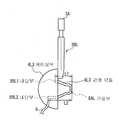
예를 들면, 도 5와 대응하는 부분에 동일 부호를 부여하고 도 25에 나타낸 바와 같이, 케이싱부(4L1)에서는, 상기 케이싱부(4L1)의 배플판(4AL)에 형성된 오목한 형상의 덕트 유지부(4L2)에 대하여, 관형 덕트(8L1)의 덕트 결합부(8L2)를 끼워맞춤으로써 장착하고, 또한 덕트 유지부(4L2)와 덕트 결합부(8L2)의 결합 상태를 해제함으로써, 관형 덕트(8L1)를 분리해 내는 것이 가능해진다.For example, the same code | symbol is attached | subjected to the part corresponding to FIG. 5, and as shown in FIG. 25, in the casing part 4L1, the concave-shaped duct holding part formed in the baffle plate 4AL of the said casing part 4L1. The tubular duct 8L1 is mounted by fitting the duct engaging portion 8L2 of the tubular duct 8L1 with respect to 4L2, and releasing the coupling state between the duct holding portion 4L2 and the duct engaging portion 8L2. ) Can be removed.
또한, 제1 실시예에 있어서는, 구멍부(8AL)로부터 내단부(8BL)까지의 덕트 길이가 각각 같은 길이로 설정된 관형 덕트(8L)를 사용하도록 한 경우에 대하여 기술하였으나, 본 발명은 이에 한정되지 않고, 각각 상이한 길이의 덕트 길이로 설정된 관형 덕트를 사용하도록 해도 된다.Further, in the first embodiment, a case has been described in which the
예를 들면, 도 4와 대응하는 부분에 동일 부호를 부여하고, 도 26에 나타낸 바와 같이, 구멍부(8AL)로부터 내단부(8BL1)까지의 길이 L1과, 구멍부(8AL)로부터 내단부(8BL2)까지의 길이 L2가 상이한 관형 덕트(8L3)가 설치된 케이싱부(4L3)에서는, 길이 L1의 덕트 부분과, 길이 L2의 덕트 부분에서는 공진 특성의 위상 어긋남이 생기고, 그 결과, 구멍부(8AL)로부터 약간 출력되는 중고역의 주파수 성분을 상쇄하고, 관형 덕트(8L3)의 구멍부(8AL)로부터 중고음이 지워진 저음만을 방사할 수 있도록 되어 있다.For example, the same code | symbol is attached | subjected to the part corresponding to FIG. 4, and as shown in FIG. 26, the length L1 from the hole part 8AL to the inner end part 8BL1, and the inner part part from the hole part 8AL ( In the casing portion 4L3 provided with the tubular duct 8L3 having a different length L2 to 8BL2, the phase shift of the resonance characteristic occurs in the duct portion of the length L1 and the duct portion of the length L2, and as a result, the hole portion 8AL It cancels the frequency component of the mid-range output slightly from), and can radiate only the low tone which the middle and high tone erased from the hole 8AL of the tubular duct 8L3.
또한, 제1 실시예에 있어서는, 밴드부(3)의 탄성력에 의해, 케이싱부(4L, 4R)의 패드부(5L, 5R)를 리스너의 두부에 대하여 맞닿게 한 상태로 유지하도록 한 경우에 대하여 기술하였으나, 본 발명은 이에 한정되지 않고, 귀걸이 행거를 리스너의 귀에 거는 것에 의해 케이싱부(4L, 4R)를 유지하도록 해도 된다. 이 경우, 관형 덕트(8L, 8R)의 선단을 외이도 입구 근방에 적극적으로 꽉 눌러, 전술한 피부 전도 작용에 의해, 리스너에 대하여 저음을 용이하게 전달시킬 수 있다.In the first embodiment, the
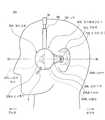
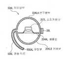
구체적으로는, 도 27 및 도 28에 나타낸 바와 같이, 이어 스피커 장치(900)는, 오디오 신호를 재생음으로 변환하는 전기 음향 변환부(902L, 902R)와, 상기 전기 음향 변환부(902L, 902R)를 리스너의 두부에 장착하여 고정시키기 위한 밴드부(903)에 의해 구성되어 있다.Specifically, as shown in FIG. 27 and FIG. 28, the
전기 음향 변환부(902L, 902R)는, 반구 형상으로 이루어지는 케이싱부(904L, 904R)를 가지고, 케이싱부(904L, 904R)의 평면 부분인 배플판(904AL, 904AR)에 대하여 오디오 신호를 재생음으로 변환하는 스피커 유닛(907L, 907R)이 장착되어 있다.The electro-acoustic converters 902L and 902R have casing parts 904L and 904R having a hemispherical shape, and the audio signal is reproduced as a reproduction sound to the baffle plates 904AL and 904AR which are planar portions of the casing parts 904L and 904R. The speaker units 907L and 907R to be converted are mounted.
또한, 케이싱부(904L, 904R)의 배플판(904AL, 904AR)에는, 소정의 경도를 가지는 알루미늄 등의 금속 또는 소정의 경도를 가지는 플라스틱이나 수지 등으로 이루어지고, 소정 굵기를 가지는 중공의 부재가 측면이 대략 U자형으로 절곡된 관형 덕트(908L, 908R)가 장착되어 있다.The baffle plates 904AL and 904AR of the casing portions 904L and 904R are made of a metal such as aluminum having a predetermined hardness or a plastic or resin having a predetermined hardness, and the hollow member having a predetermined thickness is provided. The tubular ducts 908L and 908R whose sides are bent in a substantially U-shape are mounted.
상기 관형 덕트(908L, 908R)는, 그 선단부가 각각 좌우 내측 방향으로 절곡 되어 있고, 또한 선단부의 대략 중앙에 각각 구멍부(908AL, 908AR)가 리스너의 외이도 입구와는 역방향을 향한 상태로 설치되어 있다.The end portions of the tubular ducts 908L and 908R are each bent in the left and right inward direction, and the holes 908AL and 908AR are respectively installed in the center of the tip portion in the opposite direction to the inlet of the ear canal. have.
밴드부(903)는, 중앙부(903A)를 중심으로 일반적인 인간의 두부의 형상에 맞추어 위쪽으로 볼록한 대략 아치형으로 형성되어 있는 동시에, 상기 중앙부(903A)에 대하여 신축 가능하게 슬라이드 이동할 수 있는 조절부(903BL, 903BR)에 의해 밴드부(903) 전체의 길이를 조정할 수 있도록 되어 있다.The band portion 903 is formed in a substantially arcuate shape that is convex upwardly in accordance with the shape of a general human head around the
또한, 밴드부(903)는, 일반적인 인간의 두부의 형상보다 작은 직경의 아치형으로 형성되어 있는 동시에 탄성력을 가지고 있고, 리스너에 장착될 때 케이싱부(904L, 904R)를 좌우로 넓히면서 장착되면, 장착 후에 상기 탄성력의 작용에 의해 원래의 형상으로 돌아오려고 하므로, 케이싱부(904L, 904R)를 상기 리스너의 귓바퀴 전방 위치에서 유지시키도록 되어 있다.Further, the band portion 903 is formed in an arcuate shape having a diameter smaller than that of a general human head, and has elastic force, and is mounted while widening the casing portions 904L and 904R from side to side when mounted on a listener. Since it is going to return to an original shape by the action of the elastic force, the casing portions 904L and 904R are held at the front wheel position of the listener.
이 때, 이어 스피커 장치(900)에서는, 좌측 플레이트(909L) 및 우측 플레이트(909R)를 각각 통하여 밴드부(903)의 조절부(903BL, 903BR)에 귀걸이 행거(901L, 901R)가 장착되어 있다.At this time, in the
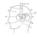
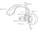
다음에, 이 귀걸이 행거(901L, 901R)의 조절부(903BL, 903BR)에 대한 장착 상태에 대하여 설명하지만, 귀걸이 행거(901L)의 조절부(903BL)에 대한 장착 상태와 귀걸이 행거(901R)의 조절부(903BR)에 대한 장착 상태는 동일하므로, 여기서는 편의상, 귀걸이 행거(901R)의 조절부(903BR)에 대한 장착 상태에 대하여만 설명한다.Next, the mounting state of the earring hangers 901L and 901R to the adjusting units 903BL and 903BR will be described. However, the mounting state of the earring hanger 901L to the adjusting unit 903BL and the earring hanger 901R are described. Since the mounting state for the adjusting unit 903BR is the same, only the mounting state for the adjusting unit 903BR of the earring hanger 901R will be described here for convenience.
도 29~도 31에 나타낸 바와 같이, 우측 플레이트(909R)가 나사(913)에 의해 케이싱부(904R)에 장착되는 동시에, 그 우측 플레이트(909R)가 나사(910, 911)에 의해 조절부(903BR)의 선단에 장착된 상태에서, 조절부(903BR)보다 외측에 위치한 우측 플레이트(909R)의 선단부에 대하여, 귓바퀴의 형상을 따라 걸리도록 만곡된 형상으로 이루어지는 귀걸이 행거(901R)가 나사(912)에 의해 장착되어 있다.As shown in FIGS. 29-31, the right side plate 909R is attached to the casing part 904R by the screw 913, and the right side plate 909R is adjusted by the screw 910, 911. 903BR, the earring hanger 901R having a curved shape so as to be hooked along the shape of the auricle with respect to the front end of the right plate 909R located outside the control unit 903BR, the screw 912 is mounted. It is attached by).
따라서, 이어 스피커 장치(900)는, 밴드부(903)의 조절부(903BL, 903BR)에 장착되어 있는 귀걸이 행거(901L, 901R)를 리스너의 귓바퀴에 걸었을 때, 귀걸이 행거(901L, 901R)가 귓바퀴를 유지하도록 하는 작용에 의해, 케이싱부(904L, 904R)를 귓바퀴 전방 위치에서 유지시킬 수 있는 동시에, 관형 덕트(908L, 908R)의 선단부를 외이도 입구 근방에 계속 강하게 누를 수 있도록 되어 있다.Therefore, the
이로써, 이어 스피커 장치(900)는, 관형 덕트(908L, 908R)에 의한 전술한 피부 전도 작용을 효과적으로 발휘하게 하여, 상기 관형 덕트(908L, 908R)의 구멍부(908AL, 908AR)로부터 출력되는 저음을 리스너에 대하여 충분히 청취할 수 있도록 되어 있다.As a result, the
또한, 관형 덕트(908L, 908R)는, 그 선단이 대략 U자형으로 형성되어 있으므로, 리스너의 외이도 입구 근방에 강하게 계속 눌러질뿐, 외이도 내로 침입하지 않도록 되어 있다. 이로써, 이어 스피커 장치(900)에 있어서도, 상기 리스너가 이어 스피커 장치(900)의 장착 시 등에, 잘못하여 관형 덕트(908L, 908R)에 의해 상기 외이도 내를 손상시키는 것을 미연에 방지할 수 있도록 되어 있다.Moreover, since the front-end | tip of tubular duct 908L, 908R is formed in substantially U-shape, it keeps being pressed strongly in the vicinity of the external auditory canal entrance of a listener, and does not intrude into an external auditory canal. Thus, even in the
그리고, 이어 스피커 장치(900)에서는, 관형 덕트(908L, 908R)의 구멍부(908AL, 908AR)가 리스너의 외이도 입구와는 역방향으로 향할 수 있지만, 관형 덕트(908L, 908R)의 구멍부(908AL, 908AR)로부터 약하게 누출되어 방사되는 저음이 지향성을 가지지 않기 때문에, 그 저음이 리스너의 외이도에 대하여 확실하게 도달할 수 있는 한편, 구멍부(908AL, 908AR)로부터 약간 누출되어 방사되는 중고음에 대하여는, 관형 덕트(908L, 908R)의 구멍부(908AL, 908AR)가 외이도 입구에 대하여 역방향을 향하고, 또한 중고음이 지향성을 가지고 있으므로, 리스너의 외이도에 거의 도달하지 않는다.In the
따라서, 이어 스피커 장치(900)에서는, 재생 음성의 중고음을 스피커 유닛(907L, 907R)으로부터 출력하여 리스너의 외이도 입구에 도달시키는 동시에, 관형 덕트(908L, 908R)의 구멍부(908AL, 908AR)로부터 재생 음성의 저음만을 리스너의 외이도 입구에 도달시키는 한편, 약간 누출되는 중고음에 대하여는 리스너의 외이도 입구와는 역방향으로 향한 구멍부(908AL, 908AR)로부터 지향성을 가진 상태로 출력되므로, 그 누출된 중고음이 리스너의 외이도 입구에 도달하지 않고, 주로 중고음이 작용하는 리스너의 음상 정위에 대하여 악영향을 주지 않도록 되어 있다.Accordingly, the
이로써, 이어 스피커 장치(900)에서는, 스피커 유닛(907L, 907R)으로부터 출력되는 중고음에 의해 자연스러운 음상 정위를 주면서, 관형 덕트(908L, 908R)의 구멍부(908AL, 908AR)를 통하여 충분한 레벨의 저음을 상기 리스너가 청취할 수 있도록 되어 있다.Thus, in the
또한, 구멍부(908AL, 908AR)의 위치로서는, 이 장소에 한정되지 않고, 리스너의 외이도 입구에 대하여 역방향을 향하기만 하면 관형 덕트(908L, 908R) 상의 어느 쪽 장소라도 된다.The positions of the hole portions 908AL and 908AR are not limited to this location, and may be any locations on the tubular ducts 908L and 908R as long as they face in the opposite direction to the inlet of the listener's ear canal.
또한, 제1 실시예에 있어서는, 케이싱부로서의 케이싱부(4L, 4R)와, 스피커 유닛으로서의 스피커 유닛(7L, 7R)과 관형 덕트로서의 관형 덕트(8L, 8R)에 의해 전기 음향 변환기로서의 전기 음향 변환부(2L, 2R)를 구성하도록 한 경우에 대하여 기술하였으나, 본 발명은 이에 한정되지 않고, 그 외 각종의 구성으로 이루어지는 케이싱부와, 스피커 유닛과, 관형 덕트에 의해 전기 음향 변환기를 구성하도록 해도 된다.Further, in the first embodiment, the electric sound as the electroacoustic transducer is provided by the
또한, 제1 실시예에 있어서는, 케이싱부로서의 케이싱부(4L, 4R)와, 스피커 유닛으로서의 스피커 유닛(7L, 7R)과, 장착부로서의 밴드부(3)와, 관형 덕트로서의 관형 덕트(8L, 8R)에 의해 이어 스피커 장치로서의 이어 스피커 장치(1)를 구성하는 경우에 대하여 기술하였으나, 본 발명은 이에 한정되지 않고, 그 외 각종의 구성으로 이루어지는 케이싱부와, 스피커 유닛과, 장착부와, 관형 덕트에 의해 이어 스피커 장치를 구성하도록 해도 된다.Further, in the first embodiment, the
(2) 제2 실시예(2) Second Embodiment
(2-1) 이어 스피커 장치의 구성(2-1) Configuration of Ear Speaker Unit
도 1과의 대응 부분에는 동일 부호를 부여한 도 32 및 도 33에 있어서, (200)은 전체적으로 제2 실시예에 있어서의 이어 스피커 장치를 나타내고, 휴대용 CD 플레이어나 DMP의 재생 처리 등에 의해 생성된 오디오 신호를 재생음으로 변환하고, 이것을 리스너가 청취하게 하도록 되어 있다.32 and 33 in which corresponding parts to those in FIG. 1 are denoted by the same reference numerals,
상기 이어 스피커 장치(200)에 있어서도, 일반적인 상자형의 스피커 장치와는 상이하고, 통상의 헤드폰 장치와 마찬가지로 리스너의 두부에 장착되는 것을 전 제로 하고 있고, 크게 나누어 오디오 신호를 재생음으로 변환하는 전기 음향 변환부(202L, 202R)와, 상기 전기 음향 변환부(202L, 202R)를 리스너의 두부에 장착하여 고정시키기 위한 밴드부(3)에 의해 구성되어 있다.Also in the
전기 음향 변환부(202L, 202R)는, 전체가 대략 구(球)형상으로 되는 케이싱부(204L, 204R)를 중심으로 구성되어 있고, 그 케이싱부(204L, 204R)에는, 각각 내부에 스피커 유닛(207L, 207R)이 설치되어 있다.The electro-
케이싱부(204L)(도 33)는, 스피커 유닛(207L)을 경계로, 전(前)방향 측에 위치하는 반구형부(204LA)와, 후방향 측에 위치하는 커버부(204LB)로 나누어지고, 반구형부(204LA)의 배플판(204AL)에는, 오디오 신호를 재생음으로 변환하는 스피커 유닛(207L)이 장착되어 있다.The
상기 스피커 유닛(207L)은, 휴대용 CD 플레이어나 DMP 등으로부터 접속 케이블(6)을 통하여 공급되는 오디오·신호에 따라 진동판을 진동시킴으로써 주로 중고음을 방음(放音)하도록 되어 있다.The
커버부(204LB)(도 33)는, 내부에 공간을 가지는 반구(半球) 형상으로 이루어지고, 배플판(204AL)의 전방 공간을 덮어 은폐하는 동시에, 그 표면의 대략 중앙에 대하여, 소정의 경도를 가지는 알루미늄 등의 금속 또는 소정의 경도를 가지는 플라스틱이나 수지 등으로 이루어지고, 소정 굵기를 가지는 중공 부재가 측면이 대략 U자형으로 굽혀진 관형 덕트(208L)가 장착되어 있다.The cover portion 204LB (FIG. 33) has a hemispherical shape having a space therein, covers the front space of the baffle plate 204AL, conceals it, and has a predetermined hardness with respect to the substantially center of the surface thereof. The
상기 관형 덕트(208L, 208R)(도 32)는, 외단부가 각각 좌우 내측 방향으로 굽혀져 있고, 또한 외단부의 대략 중앙에 각각 구멍부(208AL, 208AR)가 형성되어 있다.In the
밴드부(3)는, 중앙부(3A)를 중심으로 일반적인 인간의 두부의 형상에 맞추어 위쪽으로 볼록한 대략 아치형으로 형성되어 있는 동시에, 상기 중앙부(3A)에 대하여 신축 가능하게 슬라이드 이동할 수 있는 조절부(3BL, 3BR)에 의해 상기 밴드부(3) 전체의 길이를 조정할 수 있도록 되어 있다.The band part 3 is formed in a substantially arcuate shape which is convex upward in accordance with the shape of a general human head around the center part 3A, and at the same time, is an adjustable part 3BL that can be elastically slidably moved relative to the center part 3A. , 3BR) allows the length of the entire band portion 3 to be adjusted.
또한, 밴드부(3)는, 일반적인 인간의 두부의 형상보다 작은 직경의 아치형으로 형성되는 동시에 탄성력을 가지고 있고, 리스너에 장착될 때 케이싱부(204L, 204R)를 좌우로 넓히면서 장착되면, 장착 후에 상기 탄성력의 작용에 의해 원래의 형상으로 돌아오려고 하므로, 케이싱부(204L, 204R)를 상기 리스너의 두부에 대하여 맞닿게 한 상태로 유지시키도록 되어 있다.In addition, the band part 3 is formed in an arcuate shape having a diameter smaller than that of a general human head, and has elastic force, and when the band part 3 is mounted while widening the
그리고, 이어 스피커 장치(200)는, 좌우 대칭으로 구성되어 있으므로, 이하에서는 주로 좌측의 전기 음향 변환부(202L)를 예로 들어 설명한다.Since the
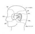
실제로, 이어 스피커 장치(200)(도 33)는, 밴드부(3)에 있어서의 길이가 조정된 후 리스너의 두부(100)에 장착됨으로써, 조절부(3BL)의 하단 측에 장착된 전기 음향 변환부(202L)를 리스너의 두부에 있어서의 귓바퀴(101L)보다도 약간 전방에 위치시키도록 되어 있다.Indeed, the speaker device 200 (FIG. 33) is mounted on the
이로써, 이어 스피커 장치(200)에서는, 밴드부(3)를 통하여 리스너에 대하여 정상적으로 장착된 경우, 케이싱부(204L)의 스피커 유닛(207L)이 귓바퀴(101L) 및 외이도 입구(102L)의 약간 전방에 위치하고, 커버부(204LB)의 관형 덕트(208L)의 구멍부(208AL)가 외이도 입구(102L)의 근방에 위치하도록 되어 있다.Thus, in the
따라서, 이어 스피커 장치(200)는, 스피커 유닛(207L)으로부터 방사된 주로 중고음을 커버부(204LB) 및 관형 덕트(208L)를 통하여, 직접 리스너의 외이도 내부에 도달하게 할 수 있으므로, 일반적인 거치형 스피커를 통하여 청취한 경우보다 중고음의 음 누출이 없는 상태에서 자연스러운 음상 정위를 줄 수 있도록 되어 있다.Therefore, the
또한, 관형 덕트(208L)는, 그 선단부가 측면이 대략 U자형으로 형성되어 있으므로, 리스너의 외이도 입구(102L)에 맞닿을 뿐 외이도 내로 침입하지 않도록 되어 있다. 이로써, 이어 스피커 장치(200)에서는, 상기 리스너가 장착 시 등에 잘못하여 관형 덕트(208L)의 선단부에 의해 상기 외이도 내부를 손상시키는 것을 미연에 방지할 수 있도록 되어 있다.Moreover, since the front-end | tip part is formed in substantially U shape at the front-end | tip part of
여기서, 도 33에 있어서의 Q3-Q4 단면을 도 34에 나타낸 바와 같이, 전기 음향 변환부(202L)의 케이싱부(204L)는 스피커 유닛(207L)의 앞면 공간이 관형 덕트(208L)의 구멍부(208AL)를 제외하고 밀폐되어 있고, 스피커 유닛(207L)에 대하여 커버부(204LB) 및 상기 관형 덕트(208L)에 의해 공진 회로를 형성하도록 되어 있다.Here, as shown in FIG. 34, the Q3-Q4 cross section in FIG. 33 is used, the
또한, 관형 덕트(208L)는, 케이싱부(204L)의 내부로부터 케이싱부(204L)의 커버부(204LB)를 통하여 리스너의 외이도 입구(102L)의 근방에 도달하고 있다. 실제로, 전기 음향 변환부(202L)는, 스피커 유닛(207L)의 앞면으로부터 방사되는 주로 중고음을, 커버부(204LB) 및 관형 덕트(208L)를 통하여 모으고, 상기 관형 덕트(208L)의 구멍부(208AL)로부터 리스너의 고막(103)에 직접 도달하게 함으로써, 음 누출이 적은 상태에서 충분한 음성 레벨의 중고음을 리스너가 청취할 수 있도록 되어 있다.Further, the
그리고, 관형 덕트(208L)는, 측면이 대략 U자형으로 형성된 것에 의해, 1개의 관형 덕트로 한 경우에 비해 그 유효 길이를 짧게 설정할 수 있는 동시에, 디자인성 및 안전성을 크게 향상시킬 수 있도록 되어 있다.Since the
그런데, 전기 음향 변환부(202L)는, 도 32 및 도 33에 나타낸 바와 같이, 리스너의 외이도 입구(102L)의 근방에 관형 덕트(208L)의 선단부를 맞닿게 할 뿐, 상기 외이도 입구(102L)를 완전하게는 폐색하지 않는다.By the way, as shown in FIG.32 and FIG.33, the
그러므로, 전기 음향 변환부(202L)는, 스피커 유닛(207L)으로부터 관형 덕트(208L)의 구멍부(208AL)를 통하여 방사되는 재생음에 더하여, 리스너의 주위에서 발생한 음(이하 이것을 주위음이라고 함)을 차단하지 않고 상기 리스너의 고막(103L)(도 34)까지 도달시켜 청취할 수 있도록 되어 있다.Therefore, in addition to the reproduction sound radiated from the
그리고, 전기 음향 변환부(202L)에서는, 소정의 경도를 가지는 알루미늄 등의 금속 또는 소정의 경도를 가지는 플라스틱이나 수지 등에 의해 관형 덕트(208L)를 형성하고, 그 관형 덕트(208L)의 선단부가 외이도 입구(102L)의 근방에 맞닿아 있으므로, 관형 덕트(208L)의 선단부에 생긴 저역의 진동 성분을, 주로 피부를 통한 전도에 의해 리스너의 고막(103L)에까지 도달시켜 청취할 수 있도록 되어 있다.In the
특히, 저음감은, 관형 덕트(208L)가 외이도 입구(102L)의 근방에 맞닿아 있으므로, 관형 덕트(208L)의 선단부에 생긴 저역의 진동에 의해 인간의 피부가 진동하여, 그것이 피부의 신경으로부터 뇌에 전해지는 것에 의해 사용자에게 체감되는 것이다.In particular, since the
이것은, 도 11에 나타낸 바와 같이, 관형 덕트(208L)의 선단부분에 있어서의 상하 방향(굵은 화살표)의 진폭량을 측정한 결과에 나타나 있다. 도 12에 나타낸 바와 같이, 알루미늄 등의 하드한 금속으로 이루어지는 관형 덕트(208L)의 선단부분에 생기는 상하 방향(굵은 화살표)의 진동 즉 상하 방향의 진폭량으로서는, 특히 약 100[Hz] 이하로 매우 큰 것을 알 수 있다.This is shown in the result of measuring the amplitude amount of the up-down direction (thick arrow) in the front-end | tip part of
또한, 도 13에 나타낸 바와 같이, 관형 덕트(208L)의 선단부분에 있어서의 전후 방향(굵은 화살표)의 진폭량을 측정한 결과, 도 14에 나타낸 바와 같이, 알루미늄 등의 하드한 금속으로 이루어지는 관형 덕트(208L)의 선단부분에 생기는 전후 방향의 진동 즉 전후 방향의 진폭량으로서도, 특히 약 100[Hz] 이하로 매우 큰 것을 알 수 있다.In addition, as shown in FIG. 13, when the amplitude amount of the front-back direction (thick arrow) in the front-end | tip part of
또한, 도 15에 나타낸 바와 같이, 관형 덕트(208L)의 선단부분에 있어서의 좌우 방향(굵은 화살표)의 진폭량을 측정한 결과, 도 16에 나타낸 바와 같이, 알루미늄 등의 하드한 금속으로 이루어지는 관형 덕트(8L)의 선단부분에 생기는 좌우 방향의 진동 즉 좌우 방향의 진폭량으로서도, 특히 약 100[Hz] 이하로 매우 큰 것을 알 수 있다.As shown in FIG. 15, the amplitude of the left and right directions (thick arrows) in the tip portion of the
이와 같이, 이어 스피커 장치(200)에서는, 관형 덕트(8L)의 선단부분에 대하여 상하 방향, 전후 방향 및 좌우 방향으로의 진동이 크게 발생하고, 이것이 리스너의 피부를 통한 전도에 의해 리스너의 고막(103L)에까지 도달하게 되므로, 중고음뿐만아니라 어느 정도의 저음에 대해서도 리스너가 청취할 수 있도록 되어 있 다.In this manner, in the
이와 같이, 이어 스피커 장치(200)는, 리스너의 두부(100)에 장착되었을 때, 스피커 유닛(207L)을 리스너의 외이도 입구(102L)로부터 약간 이격된 장소에 위치시키고, 그 스피커 유닛(207L)으로부터의 중고음을 관형 덕트(208L)를 통하여 방사하는 동시에, 케이싱부(204L)로부터 상기 외이도 입구(102L)의 근방까지 연장된 관형 덕트(208L)의 선단부에 생긴 저역의 진동 성분을 주로 피부를 통한 전도에 의해 리스너의 고막(103L)에까지 도달하게 함으로써, 자연스러운 음상 정위를 주면서 어느 정도의 저음을 포함하는 양호한 재생음을 상기 리스너가 청취할 수 있도록 되어 있다.Thus, when the
(2-2) 다른 이어 스피커 장치의 구성예(2-2) Configuration example of another ear speaker device
그런데, 제2 실시예에 있어서의 이어 스피커 장치(200)는, 도 32~도 34에 나타낸 바와 같이, 장착부로서의 밴드부(3)에 의해 전기 음향 변환부(202L, 202R)를 리스너의 두부(100)에 장착하도록 되어 있지만, 이 밴드부(3)에 대신하여 다른 각종의 장착부를 사용함으로써 전기 음향 변환부(202L, 202R)를 리스너의 두부(100)에 장착하도록 해도 된다.By the way, in the
그리고, 이하에서는, 전술한 이어 스피커 장치(200)의 경우와 마찬가지로, 주로 좌측의 전기 음향 변환부(202L)를 예로 들어 설명하지만, 우측의 전기 음향 변환부(202R)에 대해서도, 상기 좌측의 전기 음향 변환부(202L)와 좌우 대칭으로 구성되어 있는 것으로 한다.In the following description, similarly to the case of the
예를 들면, 도 17과의 대응 부분에는 동일 부호를 부여한 도 35에 나타낸 바 와 같이, 리스너의 귓바퀴(101L)에 걸기 위한 이어 클립(21L)이, 제2 실시예에 있어서의 이어 스피커 장치(200)(도 32~도 34)의 밴드부(3)에 대신하여, 전기 음향 변환부(202L)의 케이싱부(204L)에 장착된 이른바 이어 클립형의 이어 스피커 장치(220)가 고려된다.For example, as shown in Fig. 35, denoted by the same reference numerals as those in Fig. 17, the ear clip 21L for hooking on the 101L of the axle wheels of the listener is the ear speaker device according to the second embodiment ( Instead of the band part 3 of 200 (FIGS. 32 to 34), a so-called ear clip type
이 경우의 이어 스피커 장치(220)(도 35)에 있어서도, 스피커 유닛(207L)으로부터 방사된 주로 중고음을, 커버부(204LB) 및 관형 덕트(208L)를 통하여 직접 리스너의 외이도 내부에 도달하게 할 수 있으므로, 일반적인 거치형 스피커를 통하여 청취한 경우보다 중고음의 음 누출이 없는 상태로 자연스러운 음상 정위를 줄 수 있도록 되어 있다.In this case, also in the ear speaker device 220 (FIG. 35), mainly used sound emitted from the
또한, 도 18과 대응하는 부분에 동일 부호를 부여한 도 36에 나타낸 바와 같이, 제2 실시예에 있어서의 이어 스피커 장치(200)(도 32~도 34)의 좌우의 전기 음향 변환부(202L, 202R)를 접속하는 동시에 리스너의 귓바퀴(101L)에 걸기 위한 밴드부(31)가, 상기 이어 스피커 장치(200)의 밴드부(3)에 대신하여 전기 음향 변환부(202L)의 케이싱부(204L)에 장착된 이른바 언더친형의 이어 스피커 장치(230)가 고려된다.In addition, as shown in FIG. 36 which has attached | subjected the same code | symbol to the part corresponding to FIG. 18, the
이 경우의 이어 스피커 장치(230)(도 36)에 있어서도, 스피커 유닛(207L)으로부터 방사된 주로 중고음을 커버부(204LB) 및 관형 덕트(208L)를 통하여, 직접 리스너의 외이도 내부에 도달하게 할 수 있으므로, 일반적인 거치형 스피커를 통하여 청취한 경우보다 중고음의 음 누출이 없는 상태로 자연스러운 음상 정위를 줄 수 있도록 되어 있다.Also in the ear speaker device 230 (FIG. 36) in this case, it is possible to directly reach the inside of the ear canal of the listener via the cover portion 204LB and the
또한, 도 19와 대응하는 부분에 동일 부호를 부여한 도 37에 나타낸 바와 같이, 제2 실시예에 있어서의 이어 스피커 장치(200)(도 32~도 34) 좌우의 전기 음향 변환부(202L, 202R)를 접속하는 동시에 리스너의 어깨부로부터 지지하는 숄더 암(41)이, 상기 이어 스피커 장치(200)의 밴드부(3)에 대신하여 전기 음향 변환부(202L)의 케이싱부(204L)에 장착된 이른바 숄더 홀드형의 이어 스피커 장 치(240)가 고려된다.In addition, as shown in FIG. 37 with the same reference numerals as those in FIG. 19, the
이 경우의 이어 스피커 장치(240)(도 37)에 있어서도, 스피커 유닛(207L)으로부터 방사된 주로 중고음을 커버부(204LB) 및 관형 덕트(208L)를 통하여, 직접 리스너의 외이도 내부에 도달하게 할 수 있으므로, 일반적인 거치형 스피커를 통하여 청취한 경우보다 중고음의 음 누출이 없는 상태로 자연스러운 음상 정위를 줄 수 있도록 되어 있다.In this case, also in the ear speaker device 240 (FIG. 37), it is possible to directly reach the inside of the ear canal of the listener via the cover portion 204LB and the
또한, 도 20과 대응하는 부분에 동일 부호를 부여한 도 38에 나타낸 바와 같이, 제2 실시예에 있어서의 이어 스피커 장치(200)(도 32~도 34) 좌우의 전기 음향 변환부(202L, 202R)를 접속하는 동시에 리스너의 귓바퀴(101L)에 걸기 위한 밴드부(51)가, 상기 이어 스피커 장치(200)의 밴드부(3)로 바꾸어 케이싱부(204L)에 장착된 이른바 넥 밴드형의 이어 스피커 장치(250)가 고려된다.In addition, as shown in FIG. 38 which has attached | subjected the same code | symbol to the part corresponding to FIG. 20, the electro-
이 경우의 이어 스피커 장치(250)(도 38)에 있어서도, 스피커 유닛(207L)으로부터 방사된 주로 중고음을 커버부(204LB) 및 관형 덕트(208L)를 통하여, 직접 리스너의 외이도 내부에 도달하게 할 수 있으므로, 일반적인 거치형 스피커를 통하여 청취한 경우보다 중고음의 음 누출이 없는 상태로 자연스러운 음상 정위를 줄 수 있도록 되어 있다.Also in the ear speaker device 250 (FIG. 38) in this case, it is possible to make the inside of the ear canal of the listener directly through the cover portion 204LB and the
또한, 도 21과 대응하는 부분에 동일 부호를 부여한 도 39에 나타낸 바와 같이, 제2 실시예에 있어서의 이어 스피커 장치(200)(도 32~도 34)의 전기 음향 변환부(202L)를 리스너의 귓바퀴(101)보다 후방에 위치시키는 동시에, 관형 덕트(208L)에 대신하여 대략 L자형으로 이루어지는 관형 덕트(261L)가 리스너의 귓바퀴(101L)의 후방에 위치하는 케이싱부(204L)로부터 외이도 입구(102L)의 근방까지 연장된 구성의 이어 스피커 장치(260)가 고려된다.In addition, as shown in FIG. 39 with the same reference numerals as those in FIG. 21, the electro-
이 경우의 이어 스피커 장치(260)(도 39)에 있어서도, 스피커 유닛(207L)으로부터 방사된 주로 중고음을 커버부(204LB) 및 관형 덕트(261L)를 통하여, 직접 리스너의 외이도 내부에 도달하게 할 수 있으므로, 일반적인 거치형 스피커를 통하여 청취한 경우보다 중고음의 음 누출이 없는 상태에서 자연스러운 음상 정위를 줄 수 있도록 되어 있다.In this case, also in the ear speaker device 260 (FIG. 39), the main sound emitted from the
또한, 도 22와 대응하는 부분에 동일 부호를 부여한 도 40에 나타낸 바와 같이, 제2 실시예에 있어서의 이어 스피커 장치(200)(도 32~도 34)의 전기 음향 변환부(202L)에 더하여, 상기 전기 음향 변환부(202L)와 동일한 구성으로 이루어지는 후방 전기 음향 변환부(272L)를 가지고 있고, 이어 스피커 장치(200)(도 32~도 34)에 있어서의 밴드부(3)에 대신하는 밴드부(71)에 의해, 전기 음향 변환부(202L)를 귓바퀴(101L)의 전방에 위치시키는 동시에, 후방 전기 음향 변환부(272L)를 상기 귓바퀴(101L)의 후방에 위치시키도록 되어 있다.In addition, as shown in FIG. 40 with the same reference numerals as those in FIG. 22, in addition to the electro-
또한, 후방 전기 음향 변환부(272L)에는, 4채널이나 5.1채널 등의 멀티 채널 음원에 있어서의 리어 채널용의 음성 신호가 공급되도록 되어 있다.The rear
상기 이어 스피커 장치(270)(도 40)는, 리스너의 두부(100)에 장착됨으로써, 전기 음향 변환부(202L) 및 후방 전기 음향 변환부(272L)를 상기 리스너의 두부(100)에 장착할 수 있고, 전기 음향 변환부(202L) 및 후방 전기 음향 변환부(272L)에 의해 귓바퀴(101L)를 끼워넣은 상태에서 자연스러운 음상 정위를 주면서, 서라운드로 되어 충분한 저음을 포함하는 양호한 재생음을 상기 리스너가 청취할 수 있도록 되어 있다.The ear speaker device 270 (FIG. 40) is mounted on the
또한, 이 경우, 이어 스피커 장치(270)(도 40)에서는, 밴드부(71)에 대하여 가진기(75)를 장착하고, 예를 들면, 5.1채널 음원에 있어서의 중저음 성분에 따른 진동을 리스너의 두부(100)에 가하도록 해도 된다.In this case, in the ear speaker device 270 (FIG. 40), the exciter 75 is attached to the
그리고, 이어 스피커 장치(270)(도 40)는, 전기 음향 변환부(202L)로부터 관형 덕트(208L)를 리스너의 외이도 입구(102L) 근방까지 연장하는 것 외에도, 이어 스피커 장치(260)(도 39)와 마찬가지로, 후방용 전기 음향 변환부(272L)로부터 관형 덕트를 리스너의 외이도 입구(102L) 근방까지 연장하도록 하거나, 또는 전기 음향 변환부(202L) 및 후방용 전기 음향 변환부(272L)의 양쪽으로부터 관형 덕트를 리스너의 외이도 입구(102L) 근방까지 연장하도록 해도 된다.The ear speaker device 270 (FIG. 40) extends the
또한, 도 23과 대응하는 부분에 동일 부호를 부여한 도 41에 나타낸 바와 같이, 제2 실시예에 있어서의 이어 스피커 장치(200)(도 32~도 34)의 전기 음향 변환부(202L)를 리스너의 볼부분보다 앞쪽에 위치하는 밴드부(81)가 케이싱부(204L)에 장착된 이어 스피커 장치(280)가 고려된다.In addition, as shown in FIG. 41 with the same reference numerals as in FIG. 23, the electro-
또한, 케이싱부(204L)에는, 관형 덕트(208L)에 대신하여 케이싱부(204L)로부터 리스너의 외이도 입구(102L) 근방까지 연장된 관형 덕트(281L)가 설치되어 있다. 그리고, 관형 덕트(281L)는, 재생음에 있어서의 양호한 저음을 구멍부(281AL)로부터 방사할 수 있도록, 그 내경이나 음의 경로 길이 등이 적절히 계산되어 있다.The
상기 이어 스피커 장치(280)(도 41)는, 리스너의 두부(100)에 장착됨으로써, 케이싱부(204L)를 상기 리스너의 볼부분보다 전방에 위치시킬 수 있다. 이 경우, 스피커 유닛(207L)으로부터 방사된 중고음은, 상기 리스너의 볼부분 등에 있어서 반사되는 것에 의해 그 특성이 변화되므로, 이어 스피커 장치(200)의 경우와 비교하여, 일반적인 거치형의 스피커로부터 방사된 음에 한층 근접할 수 있게 된다. 이로써, 이어 스피커 장치(280)는, 한층 자연스러운 정위감을 줄 수 있는 재생음을 리스너가 청취할 수 있다.The ear speaker device 280 (FIG. 41) is mounted on the
이와 같이, 본 발명에서는, 이어 스피커 장치(200)의 밴드부(3)(도 32~도 34) 이외에도, 이어 스피커 장치(220)~(280)(도 35~도 41)와 같은 각종의 방식으로 이루어지는 장착부에 의해, 전기 음향 변환부(202L, 202R)를 리스너의 두부(100)에 대하여 장착시키도록 해도 된다.As described above, in the present invention, in addition to the band portion 3 (FIGS. 32 to 34) of the
(2-3) 제2 실시예에 있어서의 동작 및 효과(2-3) Operation and Effects in Example 2
이상의 구성에 있어서, 이어 스피커 장치(200)는, 리스너의 두부(100)에 장착됨으로써, 전기 음향 변환부(202L)의 케이싱부(204L)에 설치된 스피커 유닛(207L)으로부터 주로 방사되는 중고음을 커버부(204LB)로부터 관형 덕트(208L)를 통하여 모아서 외이도 입구(102L)의 근방에 위치한 관형 덕트(208L)의 구멍부(208AL)로부터 상기 중고음을 출력시킨다.In the above configuration, the
따라서, 이어 스피커 장치(200)의 전기 음향 변환부(202L)는, 스피커 유닛(207L)으로부터 방사된 중고음을, 관형 덕트(208L)의 구멍부(208AL)로부터만 고막(103L)에 직접 도달시킬 수 있으므로, 일반적인 스피커를 통하여 리스너에게 청취시키는 경우와 유사한 특성의 재생음을 음 누출 없이 청취할 수 있는 동시에, 음상이 두부 밖에 위치하고 있는 것 같은 자연스러운 정위감을 부여할 수도 있다.Therefore, the
또한, 이어 스피커 장치(200)는, 관형 덕트(208L)의 구멍부(208L)를 외이도 입구(102L)의 근방에 위치시킬 뿐이며, 밀폐형의 헤드폰과 같이 외이도 입구(102L)를 막아 버리지 않기 때문에, 관형 덕트(208L)의 구멍부(208AL)로부터 출력되는 재생음뿐아니라, 주위음에 대해서도 차단되지 않고 고막(103)에 닿게 할 수 있고, 따라서, 관형 덕트(208L)를 통하여 재생음을 청취하게 하면서 외부의 주위음에 대해서도 청취할 수 있다.In addition, since the
이로써, 이어 스피커 장치(200)에서는, 리스너가 보행할 때나 스포츠를 행할 때 등, 리스너가 주위음에 대하여 청취할 필요가 있는 경우에도, 관형 덕트(208L)의 구멍부(208AL)로부터 출력되는 재생음에 더하여 주위음에 대해서도 확실하게 청취할 수 있다.As a result, in the
또한, 이어 스피커 장치(200)는, 리스너의 귓바퀴(101L) 등을 전기 음향 변환부(202L)에 의해 덮어버리지 않으므로, 일반적인 헤드폰을 장착한 리스너가 느끼는 것 같은 폐색감이나 후덥지근한 것 같은 불쾌감을 주지 않는다. 또한, 이어 스 피커 장치(200)에서는, 밀폐 공간을 형성하지 않기 때문에, 밀폐형 헤드폰을 사용한 경우에 생길 수 있는, 외이도에 있어서의 공진 주파수의 변화가 생기지 않아 리스너에게 위화감을 주지도 않는다.In addition, since the
이에 더하여, 이어 스피커 장치(200)는, 재생음의 방사구인 관형 덕트(208L)의 구멍부(208AL)가 고막(103L)에 근접함으로써 리스너가 충분한 음량 레벨의 중고음을 청취할 수 있는 동시에 관형 덕트(208L)의 선단부에 생긴 저역의 진동에 의해 어느 정도의 저음도 상기 리스너가 청취할 수 있으므로, 스피커 유닛(207L)의 구경을 불필요하게 크게 할 필요가 없어, 케이싱부(204L)의 크기를 필요 최소한으로 억제할 수가 있다.In addition, the
이로써, 이어 스피커 장치(200)에서는, 전체의 크기나 중량을 필요 최소한으로 억제할 수 있으므로, 리스너가 이어 스피커 장치(200)를 장착했을 때의 크기나 무게에 의한 번거로움을 매우 억제할 수 있다.As a result, in the
이상의 구성에 의하면, 이어 스피커 장치(200)는, 리스너의 두부(100)에 장착되었을 때, 전기 음향 변환부(202L)의 스피커 유닛(207L)을 상기 리스너의 외이도 입구(102L)보다 약간 전방에 위치시키는 동시에, 스피커 유닛(207L)으로부터 주로 방사되는 중고음이 커버부(204LB)로부터 관형 덕트(208L)를 통하여 외부로 누출되지 않고 모이므로, 외이도 입구(102L)의 근방에 위치한 관형 덕트(208L)의 구멍부(208AL)로부터 음성 신호에 근거한 재생음을 출력함으로써, 관형 덕트(208L)의 구멍부(208AL)로부터 방사되는 중고음을 충분한 음압 레벨로 고막(103)에 도달시키는 것이 가능하므로, 자연스러운 음상 정위를 주면서 충분한 음압 레벨로 되는 양 호한 재생음을 리스너가 청취할 수 있다.According to the above structure, when the
(2-4) 제2 실시예에 대한 다른 실시예(2-4) Another Example of Example 2
그리고, 전술한 제2 실시예에 있어서는, 관형 덕트(208L)가 측면이 대략 U자형으로 형성되고, 구멍부(8AR)를 경계로 2개의 관형 덕트에 의해 구성하도록 한 경우에 대하여 기술하였으나, 본 발명은 이에 한정되지 않고, 상기 관형 덕트(208L)를 1개나 3개 이상의 관형 덕트에 의해 구성하도록 해도 된다.In the second embodiment described above, the
예를 들면, 도 42에 나타낸 바와 같이, 이어 스피커 장치(290)의 전기 음향 변환부(292L)에 있어서는, 케이싱부(204L)에 있어서의 커버부(204LB)의 표면으로부터 1개의 관형 덕트(298L)가 후방으로 연장되도록 해도 되고, 또한 상기 관형 덕트(298L)의 뒤쪽 선단부에 리스너의 외이도 입구(102L)를 손상시키지 않기 위한 보호부(299L)가 장착되어 있어도 된다. 이 경우, 보호부(299L)는, 음을 통하기 쉬운 스펀지형의 부재 등으로 구성되는 것에 의해, 주위음을 차단시키지 않고 리스너가 청취할 수 있다.For example, as shown in FIG. 42, in the
또한, 제2 실시예에 있어서는, 금속 등의 단단한 재료로 형성된 관형 덕트(208L)를 사용하도록 한 경우에 대하여 기술하였으나, 본 발명은 이에 한정되지 않고, 가요성을 가지는 수지 등의 부드러운 재료로 형성된 관형 덕트(208L)를 사용하도록 해도 된다. 이 경우, 상기 관형 덕트(208L)의 재료의 차이를 고려한 후 내경이나 경로 길이가 설계되는 것이 바람직하다.In addition, in the second embodiment, the case in which the
또한, 제2 실시예에 있어서는, 이어 스피커 장치(200)가 리스너의 두부(100)(도 33)에 장착되었을 때, 스피커 유닛(207L)의 방음면이 대략 후방향을 향 하도록 한 경우에 대하여 기술하였으나, 본 발명은 이에 한정되지 않고, 예를 들면, 스피커 유닛(207L)의 방음면이 약간 내측을 향하도록 해도 되고, 중요한 것은 상기 스피커 유닛(207L)의 방음면이 대체로 외이도 입구(102L) 방향을 향하여, 방사되는 중고음이 양호한 효율로 고막(103L)에 도달되면 된다.In addition, in the second embodiment, when the
또한, 제2 실시예에 있어서는, 이어 스피커 장치(200)가 좌우의 전기 음향 변환부(202L, 202R)를 가지고, 2채널의 재생음을 출력하도록 한 경우에 대하여 기술하였으나, 본 발명은 이에 한정되지 않고, 예를 들면, 좌측의 전기 음향 변환부(202L)만을 가지고 1채널의 재생음을 출력하도록 해도 된다.In addition, in the second embodiment, the case where the
또한, 제2 실시예에 있어서는, 케이싱부(204L)에 중고음용의 스피커 유닛(207L)을 설치하도록 한 경우에 대하여 기술하였으나, 본 발명은 이에 한정되지 않고, 예를 들면, 중음용 및 고음용이라는 2개의 스피커 유닛을 1개의 케이싱부(204L)에 설치하여 투웨이 스피커로 하는 등, 복수개의 스피커 유닛을 케이싱부(204L)에 설치하도록 해도 된다.In addition, in the second embodiment, the case where the
또한, 제2 실시예에 있어서는, 반구 형상의 커버부(204LB)를 사용하도록 한 경우에 대하여 기술하였으나, 본 발명은 이에 한정되지 않고, 예를 들면, 사각뿔이나 삼각뿔 등의 형상이라도 되고, 중요한 것은 스피커 유닛(207L)으로부터 출력된 중고음을 모으고, 또한 외부로 새지 않는 구조이면 된다.In the second embodiment, the case in which the hemispherical cover portion 204LB is used is described. However, the present invention is not limited thereto, and may be, for example, a square pyramid or a triangular pyramid. What is necessary is just a structure which collects the used sounds output from the
또한, 제2 실시예에 있어서는, 스피커 유닛(207L)의 후방을 폐색한 구조의 반구형부(204LA)가 설치된 케이싱부(204L)를 사용하도록 한 경우에 대하여 기술하였으나, 본 발명은 이에 한정되지 않고, 도 43에 나타낸 바와 같이, 스피커 유 닛(207L)의 후방에 관통 구멍(305~308)이 형성되는 동시에, 그 관통 구멍(305~308)을 내측으로부터 막도록 한 스펀지 등으로 이루어지는 음향 저항체(309)가 장착된 반구형부(304LA)를 가지는 케이싱부(304L)를 사용하도록 해도 된다.In addition, in the second embodiment, a case has been described in which a
이 경우의 케이싱부(304L)(도 43)에서는, 스피커 유닛(207L)의 후방측이 관통 구멍(305~308)에 의해 개방된 것에 의해, 상기 스피커 유닛(207L)의 진동판이 오디오 신호에 대하여 추종하기 쉬워지는 동시에, 관통 구멍(305~308)이 형성된 것에 의한 음질의 저하를 음향 저항체(309)에 의해 방지할 수 있으므로, 고음질의 중고음을 관형 덕트(208L)의 구멍부(208AL)로부터 방사할 수 있다.In this case, in the casing portion 304L (FIG. 43), the rear side of the
또한, 케이싱부(304L)(도 43)에서는, 음향 저항체(309)가 반드시 필요한 것은 아니고, 필요에 따라 음향 저항체(3O9)를 장착하고, 또한 그 길이 및 두께를 변경한 것을 장착함으로써 음질을 조정할 수 있다.In addition, in the casing portion 304L (FIG. 43), the acoustic resistor 309 is not necessarily required, and if necessary, the
또한, 제2 실시예에 있어서는, 스피커 유닛(207L)의 후방을 폐색한 구조의 반구형부(204LA)가 설치된 케이싱부(204L)를 사용하도록 한 경우에 대하여 기술하였으나, 본 발명은 이에 한정되지 않고, 도 44에 나타낸 바와 같이, 스피커 유닛(207L)의 전방에 관통 구멍(405~408)이 형성되는 동시에, 그 관통 구멍(405~408)을 내측으로부터 막도록 한 스펀지 등으로 이루어지는 음향 저항체(409, 410)가 장착된 커버부(404LB)를 가지는 케이싱부(404L)를 사용하도록 해도 된다.In addition, in the second embodiment, a case has been described in which a
이 경우의 케이싱부(404L)(도 44)에서는, 스피커 유닛(207L)의 전방측이 관통 구멍(405~408)에 의해 개방된 것에 의해 상기 스피커 유닛(207L)의 진동판이 오디오 신호에 대하여 추종하기 쉬워지는 동시에, 관통 구멍(405~408)이 형성된 것에 의한 음질의 저하를 음향 저항체(409, 410)에 의해 방지할 수 있으므로, 고음질의 중고음을 관형 덕트(208L)의 구멍부(208AL)로부터 방사할 수 있다.In this case, in the casing portion 404L (FIG. 44), the front side of the
또한, 케이싱부(404L)(도 44)에 있어서도, 음향 저항체(409, 410)가 반드시 필요한 것은 아니고, 필요에 따라 음향 저항체(409, 410)를 장착하고, 또한 그 길이 및 두께를 변경한 것을 장착함으로써 음질을 조정할 수 있다.In addition, in the casing part 404L (FIG. 44), the acoustic resistors 409 and 410 are not necessarily required, but the acoustic resistors 409 and 410 were attached as needed, and the length and thickness were changed. Sound quality can be adjusted by attaching.
또한, 제2 실시예에 있어서는, 커버부(204LB)의 표면에 관형 덕트(208L)가 설치된 케이싱부(204L)를 사용하도록 한 경우에 대하여 기술하였으나, 본 발명은 이에 한정되지 않고, 도 45에 나타낸 바와 같이, 반구형부(504LA)의 표면에 관형 덕트(508L)가 일체로 설치된 케이싱부(504L)를 사용하도록 해도 된다.Incidentally, in the second embodiment, the case in which the
이 경우, 케이싱부(504L)(도 45)는 이른바 켈톤형(kelton type)의 스피커 장치와 동일한 구조를 가지게 되어, 스피커 유닛(207L)의 전방의 공간에 중고음을 가두는 한편, 스피커 유닛(207L)의 후방으로부터 소정의 주파수 대역의 저음만을, 관형 덕트(508L)의 구멍부(508AL)를 통하여 방사시킬 수 있다.In this case, the casing portion 504L (FIG. 45) has the same structure as the so-called Kelton type speaker device, confining the mid to high sound in the space in front of the
또한, 케이싱부(504L)(도 45)의 구조로서는, 이에 한정되지 않고, 스피커 유닛(207L)의 후방을 반구형부에 의해 폐색하고, 커버부(204LB)의 표면의 어딘가에 관형 덕트를 형성함으로써 켈톤형으로 하는 것도 고려할 수 있다.In addition, the structure of the casing portion 504L (FIG. 45) is not limited to this, and the rear of the
또한, 제2 실시예에 있어서는, 커버부(204LB)의 표면에 관형 덕트(208L)가 일체화된 상태로 형성된 케이싱부(204L)를 사용하도록 한 경우에 대하여 기술하였으나, 본 발명은 이에 한정되지 않고, 도 46에 나타낸 바와 같이 커버부(604LB)에 형성된 결합부(604LBS)와, 관형 덕트(608L)의 한쪽에 형성된 유지부(608LS)를 서로 끼워맞춤으로써, 상기 관형 덕트(608L)가 커버부(604LB)에 대하여 착탈 가능하게 설치된 구성의 케이싱부(604L)를 사용하도록 해도 된다.In the second embodiment, the case where the
이로써, 케이싱부(604L)(도 46)에서는, 리스너에 있어서 필요할 때만 관형 덕트(608L)가 장착된 상태로 사용되고, 리스너에 있어서 불필요할 때는 관형 덕트(608L)가 분리한 상태로 사용되게 되므로, 리스너의 사용 편리성을 대폭 향상시킬 수 있다.Thus, in the casing portion 604L (FIG. 46), the tubular duct 608L is used only when necessary for the listener, and when the tubular duct 608L is used when the listener is not necessary, the tubular duct 608L is used. The usability of the listener can be greatly improved.
또한, 제2 실시예에 있어서는, 커버부(204LB)의 내측으로서, 관형 덕트(208L)의 밑 부분에 에지가 남은 상태의 케이싱부(204L)(도 34)를 사용하도록 한 경우에 대하여 기술하였으나, 본 발명은 이에 한정되지 않고, 도 47에 나타낸 바와 같이 커버부(704LB)의 내측으로서, 관형 덕트(708L)의 밑 부분에 R형의 라운드부(711)가 형성된 케이싱부(704L)를 사용하도록 해도 된다.In addition, in the second embodiment, the case where the
상기 케이싱부(704L)에서는, 스피커 유닛(207L)의 앞면측으로부터 밀려 나오는 공기가 에지에 맞닿아 풍절음이 발생하지 않고, 고음질의 중고음만을 관형 덕트(708L)의 구멍부(708AL)로부터 방사할 수 있다.In the casing portion 704L, the air pushed out from the front side of the
또한, 제2 실시예에 있어서는, 커버부(204LB)의 표면에 관형 덕트(208L)가 일체화된 상태로 형성된 케이싱부(204L)를 사용하도록 한 경우에 대하여 기술하였으나, 본 발명은 이에 한정되지 않고, 커버부(204LB)와 관형 덕트(208L)를 구별하지 않고, 스피커 유닛(207L)의 앞면측을 감싸는 것 같은 형상으로 선단을 향함에 따라 가는 관형으로 형성된 관형 덕트가 배플판(204AL)에 장착된 구조의 케이싱부를 사용하도록 해도 된다.In the second embodiment, the case where the
또한, 제2 실시예에 있어서는, 구멍부(208AL)를 중심으로 한 커버부(204LB)의 표면까지의 덕트 길이가 각각 같은 길이로 설정된 관형 덕트(208L)를 사용하도록 한 경우에 대하여 기술하였으나, 본 발명은 이에 한정되지 않고, 각각 상이한 길이의 덕트 길이로 설정된 관형 덕트를 사용하도록 해도 된다.In addition, in the second embodiment, a case has been described in which the
예를 들면, 도 26과 대응하는 부분에 동일 부호를 부여한 도 48에 나타낸 바와 같이, 구멍부(808AL)로부터 내단부(808BL1)까지의 길이 L3와, 구멍부(808AL)로부터 내단부(808BL2)까지의 길이 L4가 상이한 관형 덕트(808L)가 설치된 케이싱부(804L)에서는, 길이 L3의 덕트 부분과, 길이 L4의 덕트 부분에서는 서로 공진 특성의 위상 어긋남이 생기고, 그 결과, 구멍부(808AL)로부터 약간 출력되는 중고역의 주파수 성분을 상쇄하고, 관형 덕트(208L2)의 구멍부(808AL)로부터 중고음이 지워진 저음만을 방사할 수 있도록 되어 있다.For example, as shown in FIG. 48, in which portions corresponding to those in FIG. 26 are given the same reference numerals, the length L3 from the hole portion 808AL to the inner end portion 808BL1, and the inner end portion 808BL2 from the hole portion 808AL are shown in FIG. In the casing portion 804L provided with the tubular duct 808L having a different length L4 up to, the phase shift of the resonance characteristic occurs between the duct portion of the length L3 and the duct portion of the length L4, and as a result, the hole portion 808AL. The frequency component of the mid-range that is slightly outputted from the phase is canceled, and only the low tone from which the mid-tone is erased can be radiated from the hole 808AL of the tubular duct 208L2.
또한, 제2 실시예에 있어서는, 케이싱부로서의 케이싱부(204L, 204R)과, 스피커 유닛으로서의 스피커 유닛(207L, 207R)과, 관형 덕트로서의 관형 덕트(208L, 208R)에 의해 전기 음향 변환기로서의 전기 음향 변환부(202L, 202R)를 구성하도록 한 경우에 대하여 기술하였으나, 본 발명은 이에 한정되지 않고, 그 외 각종의 구성으로 이루어지는 케이싱부와, 스피커 유닛과, 관형 덕트에 의해 전기 음향 변환기를 구성하도록 해도 된다.Further, in the second embodiment, the
또한, 제2 실시예에 있어서는, 케이싱부로서의 케이싱부(204L, 204R)와, 스피커 유닛으로서의 스피커 유닛(207L, 207R)과, 장착부로서의 밴드부(3)와, 관형 덕트로서의 관형 덕트(208L, 208R)에 의해 이어 스피커 장치로서의 이어 스피커 장 치(1)를 구성하는 경우에 대하여 기술하였으나, 본 발명은 이에 한정되지 않고, 그 외 각종의 구성으로 이루어지는 케이싱부와, 스피커 유닛과, 장착부와, 관형 덕트에 의해 이어 스피커 장치를 구성하도록 해도 된다.Further, in the second embodiment, the
본 발명은, 베이스 리플렉스형의 스피커 이외에도, 백로드혼형 등 이외에, 각종의 덕트를 가지는 스피커 장치를 리스너의 두부에 장착시키는 각종의 이어 스피커 장치에도 이용할 수 있다.The present invention can be used not only for a bass reflex type speaker but also for a variety of ear speaker devices for attaching a speaker device having various ducts to the head of the listener, in addition to the back rod horn type.
Claims (36)
Translated fromKoreanApplications Claiming Priority (4)
| Application Number | Priority Date | Filing Date | Title |
|---|---|---|---|
| JP2006024957 | 2006-02-01 | ||
| JPJP-P-2006-024957 | 2006-02-01 | ||
| JPJP-P-2006-328603 | 2006-12-05 | ||
| JP2006328603 | 2006-12-05 |
Publications (1)
| Publication Number | Publication Date |
|---|---|
| KR20080097906Atrue KR20080097906A (en) | 2008-11-06 |
Family
ID=38327585
Family Applications (1)
| Application Number | Title | Priority Date | Filing Date |
|---|---|---|---|
| KR1020077021819AAbandonedKR20080097906A (en) | 2006-02-01 | 2007-02-01 | Electro-acoustic transducer and ear speaker unit |
Country Status (5)
| Country | Link |
|---|---|
| US (1) | US8213632B2 (en) |
| JP (1) | JP4930382B2 (en) |
| KR (1) | KR20080097906A (en) |
| CN (1) | CN101310557B (en) |
| WO (1) | WO2007089033A1 (en) |
Families Citing this family (28)
| Publication number | Priority date | Publication date | Assignee | Title |
|---|---|---|---|---|
| US20030230921A1 (en)* | 2002-05-10 | 2003-12-18 | George Gifeisman | Back support and a device provided therewith |
| JP4900138B2 (en)* | 2007-08-24 | 2012-03-21 | ソニー株式会社 | Ear speaker device |
| US8175316B2 (en)* | 2006-12-05 | 2012-05-08 | Sony Corporation | Ear speaker device |
| JP2011160182A (en)* | 2010-02-01 | 2011-08-18 | Toshitaka Takei | Headphone with ultrasonic radiator directly attached to housing |
| JP5367658B2 (en)* | 2010-08-24 | 2013-12-11 | エムケー電子株式会社 | Ear speaker |
| US20120308068A1 (en)* | 2011-06-03 | 2012-12-06 | Yueh-Hua Hsu Huang | Head multi-directional audio device |
| US8649547B2 (en)* | 2011-12-15 | 2014-02-11 | Jazz Hipster Corporation | Mountable multi-directional audio device |
| DK2747459T3 (en)* | 2012-12-21 | 2018-12-17 | Sonion Nederland Bv | RIC unit with Thuras tube |
| US8977376B1 (en) | 2014-01-06 | 2015-03-10 | Alpine Electronics of Silicon Valley, Inc. | Reproducing audio signals with a haptic apparatus on acoustic headphones and their calibration and measurement |
| US10986454B2 (en) | 2014-01-06 | 2021-04-20 | Alpine Electronics of Silicon Valley, Inc. | Sound normalization and frequency remapping using haptic feedback |
| US8767996B1 (en) | 2014-01-06 | 2014-07-01 | Alpine Electronics of Silicon Valley, Inc. | Methods and devices for reproducing audio signals with a haptic apparatus on acoustic headphones |
| CN106572940B (en)* | 2014-03-19 | 2019-12-06 | 科帕动物保健公司 | Sensory stimulation or monitoring device for the back of the neck |
| FR3020737B1 (en)* | 2014-05-05 | 2017-10-20 | Chene Richard | DEVICE FOR TRANSMITTING SOUNDS FOR INTRA-AURICULAR HEADER AND INTRA-AURICULAR HEADER |
| US20170272850A1 (en)* | 2014-10-30 | 2017-09-21 | Sony Corporation | Sound output device |
| JPWO2016067700A1 (en)* | 2014-10-30 | 2017-08-10 | ソニー株式会社 | Sound output device and sound guide device |
| US20160134958A1 (en)* | 2014-11-07 | 2016-05-12 | Microsoft Technology Licensing, Llc | Sound transmission systems and devices having earpieces |
| CN107113481B (en)* | 2014-12-18 | 2019-06-28 | 株式会社精好 | Cartilage conduction hearing device using electromagnetic vibration unit and electromagnetic vibration unit |
| WO2016103983A1 (en)* | 2014-12-24 | 2016-06-30 | 株式会社テムコジャパン | Bone conduction headphone |
| US9794677B2 (en) | 2016-01-12 | 2017-10-17 | Bose Corporation | Headphone |
| JPWO2017168903A1 (en)* | 2016-03-29 | 2019-02-07 | ソニー株式会社 | Sound playback device |
| WO2017185048A1 (en) | 2016-04-21 | 2017-10-26 | Human, Incorporated | Attachment apparatus for coupling to an ear |
| JP6363241B1 (en)* | 2017-03-08 | 2018-07-25 | シャープ株式会社 | Wearable speaker system |
| CN107135456B (en)* | 2017-04-27 | 2020-12-08 | 歌尔智能科技有限公司 | Sound box air leakage detection device and method and computer readable storage medium |
| US10904667B1 (en)* | 2018-03-19 | 2021-01-26 | Amazon Technologies, Inc. | Compact audio module for head-mounted wearable device |
| CN109788386B (en)* | 2019-01-05 | 2024-01-26 | 深圳市韶音科技有限公司 | Bone conduction speaker device and earhook manufacturing method |
| USD934197S1 (en) | 2019-03-24 | 2021-10-26 | Buddy Snow | Headphones |
| USD940684S1 (en)* | 2019-03-24 | 2022-01-11 | Buddy Snow | Earphones |
| EP4088485A1 (en)* | 2020-01-10 | 2022-11-16 | WÖLFL, Genaro | Transducer arrangements for head- and earphones |
Family Cites Families (26)
| Publication number | Priority date | Publication date | Assignee | Title |
|---|---|---|---|---|
| JPS5268401A (en) | 1975-12-05 | 1977-06-07 | Victor Co Of Japan Ltd | Headphone and listening device for listening 4 channel sound signals |
| JPH0220199A (en) | 1988-07-08 | 1990-01-23 | Sony Corp | Electroacoustic transducer |
| JPH0354295A (en) | 1989-07-21 | 1991-03-08 | Res Assoc Util Of Light Oil | Purification of light hydrocarbon and adsorbent for purification of light hydrocarbon |
| JPH03117999A (en)* | 1989-09-30 | 1991-05-20 | Sony Corp | Electroacoustic transducer and acoustic reproduction system |
| JPH03162099A (en)* | 1989-11-20 | 1991-07-12 | Sony Corp | Headphone device |
| JP2814772B2 (en) | 1991-05-16 | 1998-10-27 | ソニー株式会社 | Earbud headphones |
| JP3054295B2 (en) | 1993-06-28 | 2000-06-19 | トクミ電子工業株式会社 | headphone |
| US6301367B1 (en)* | 1995-03-08 | 2001-10-09 | Interval Research Corporation | Wearable audio system with acoustic modules |
| US5694475A (en)* | 1995-09-19 | 1997-12-02 | Interval Research Corporation | Acoustically transparent earphones |
| CA2295750A1 (en)* | 1997-07-18 | 1999-01-28 | Resound Corporation | Behind the ear hearing aid system |
| US6681022B1 (en)* | 1998-07-22 | 2004-01-20 | Gn Resound North Amerca Corporation | Two-way communication earpiece |
| US6101259A (en)* | 1998-08-03 | 2000-08-08 | Motorola, Inc. | Behind the ear communication device |
| JP3623127B2 (en)* | 1998-12-25 | 2005-02-23 | 松下電器産業株式会社 | Headphone device |
| JP2003018693A (en)* | 2001-06-28 | 2003-01-17 | Mitsubishi Electric Corp | 3D sound image output device |
| KR20010103813A (en) | 2001-08-24 | 2001-11-24 | 김성일 | Bass reflex-type headphone |
| US20030112992A1 (en)* | 2001-12-14 | 2003-06-19 | Rapps Gary M. | Self-retaining element for a behind-the-ear communication device |
| US7082207B2 (en)* | 2001-12-14 | 2006-07-25 | Motorola, Inc. | Adjustable behind-the-ear communication device |
| CN2645390Y (en)* | 2002-03-04 | 2004-09-29 | 朱斯忠 | Phase reversal earphone |
| DE60326704D1 (en)* | 2002-03-06 | 2009-04-30 | Koninkl Philips Electronics Nv | HEADPHONE |
| CN1720763B (en) | 2002-07-26 | 2013-06-12 | 奥克利有限公司 | Glasses |
| US7499555B1 (en)* | 2002-12-02 | 2009-03-03 | Plantronics, Inc. | Personal communication method and apparatus with acoustic stray field cancellation |
| US7499562B2 (en)* | 2003-09-22 | 2009-03-03 | Soon-Teak Shim | Virtual multi-channel speaker unit |
| JP4221746B2 (en)* | 2003-10-02 | 2009-02-12 | 勇 小泉 | Headphone device |
| DE202004003078U1 (en)* | 2004-02-25 | 2005-07-07 | Rundfeldt, Hans Arnold, Dr.med. | Rear head holder for speech recognition and telephone systems consisting of circular elements abutting top of rear skull via round earpiece members of loop, held behind neck and held by spectacles frame, with adjustable counter holder |
| JP2005269585A (en) | 2004-03-18 | 2005-09-29 | Junichi Suzuki | Telephone conversation listening-in auditory meatus insertion pipe and standing-installation storage mechanism |
| US7920902B2 (en)* | 2007-04-04 | 2011-04-05 | Carroll David W | Mobile personal audio device |
- 2007
- 2007-02-01KRKR1020077021819Apatent/KR20080097906A/ennot_activeAbandoned
- 2007-02-01JPJP2007556952Apatent/JP4930382B2/ennot_activeExpired - Fee Related
- 2007-02-01USUS11/910,321patent/US8213632B2/ennot_activeExpired - Fee Related
- 2007-02-01WOPCT/JP2007/052164patent/WO2007089033A1/enactiveApplication Filing
- 2007-02-01CNCN2007800001549Apatent/CN101310557B/ennot_activeExpired - Fee Related
Also Published As
| Publication number | Publication date |
|---|---|
| JP4930382B2 (en) | 2012-05-16 |
| US8213632B2 (en) | 2012-07-03 |
| US20090154755A1 (en) | 2009-06-18 |
| WO2007089033A1 (en) | 2007-08-09 |
| CN101310557A (en) | 2008-11-19 |
| CN101310557B (en) | 2012-01-04 |
| JPWO2007089033A1 (en) | 2009-06-25 |
Similar Documents
| Publication | Publication Date | Title |
|---|---|---|
| KR20080097906A (en) | Electro-acoustic transducer and ear speaker unit | |
| US8175316B2 (en) | Ear speaker device | |
| JP3057731B2 (en) | Electroacoustic transducer and sound reproduction system | |
| JP5367658B2 (en) | Ear speaker | |
| US6062337A (en) | Audio system that can be mounted on the body of a user | |
| WO2019146138A1 (en) | Hearing device | |
| JP2007235922A (en) | Electro-acoustic converter and ear speaker device | |
| JP4952223B2 (en) | Ear speaker device | |
| US20250097619A1 (en) | Headphones comprising a plurality of acoustic elements | |
| JP4826467B2 (en) | Electroacoustic transducer and ear speaker device | |
| JP2018142769A (en) | Dummy head and ear plug | |
| JP4826455B2 (en) | Ear speaker device and glasses-type image display device | |
| JP4826456B2 (en) | Electroacoustic transducer and ear speaker device | |
| JP2008141690A (en) | Electroacoustic transducer and ear speaker apparatus | |
| JP2018137682A (en) | Dummy head and ear plug | |
| CN1465206A (en) | sound installation | |
| JP3198509B2 (en) | Playback device | |
| JP4826454B2 (en) | Ear speaker device | |
| JP4826457B2 (en) | Electroacoustic transducer and ear speaker device | |
| JP2007235917A (en) | Electro-acoustic converter and ear speaker device | |
| JPH0354990A (en) | Ear microphone and using method thereof | |
| JP2008060943A (en) | Earphone attachment | |
| JP6629283B2 (en) | Canal type earphone and adapter for canal type earphone | |
| JPH11127500A (en) | Bi-noral reproducing device, headphone for binaural reproduction and sound source evaluating method | |
| JPH071957B2 (en) | Microphone for telephone recording |
Legal Events
| Date | Code | Title | Description |
|---|---|---|---|
| PA0105 | International application | Patent event date:20070921 Patent event code:PA01051R01D Comment text:International Patent Application | |
| PG1501 | Laying open of application | ||
| A201 | Request for examination | ||
| PA0201 | Request for examination | Patent event code:PA02012R01D Patent event date:20111229 Comment text:Request for Examination of Application | |
| E902 | Notification of reason for refusal | ||
| PE0902 | Notice of grounds for rejection | Comment text:Notification of reason for refusal Patent event date:20121115 Patent event code:PE09021S01D | |
| E701 | Decision to grant or registration of patent right | ||
| PE0701 | Decision of registration | Patent event code:PE07011S01D Comment text:Decision to Grant Registration Patent event date:20130503 | |
| PC1904 | Unpaid initial registration fee |