KR20080091516A - Microsurgical Instruments - Google Patents
Microsurgical InstrumentsDownload PDFInfo
- Publication number
- KR20080091516A KR20080091516AKR1020087021825AKR20087021825AKR20080091516AKR 20080091516 AKR20080091516 AKR 20080091516AKR 1020087021825 AKR1020087021825 AKR 1020087021825AKR 20087021825 AKR20087021825 AKR 20087021825AKR 20080091516 AKR20080091516 AKR 20080091516A
- Authority
- KR
- South Korea
- Prior art keywords
- cutting member
- port
- cutting
- wall portion
- microsurgical
- Prior art date
- Legal status (The legal status is an assumption and is not a legal conclusion. Google has not performed a legal analysis and makes no representation as to the accuracy of the status listed.)
- Granted
Links
- 238000005520cutting processMethods0.000claimsabstractdescription96
- 239000000523sampleSubstances0.000claimsdescription34
- 238000000034methodMethods0.000claimsdescription5
- 239000012530fluidSubstances0.000description11
- 210000001525retinaAnatomy0.000description6
- 238000001356surgical procedureMethods0.000description4
- 238000004891communicationMethods0.000description3
- 238000001802infusionMethods0.000description3
- 239000000835fiberSubstances0.000description2
- 238000012986modificationMethods0.000description2
- 230000004048modificationEffects0.000description2
- 210000004127vitreous bodyAnatomy0.000description2
- RTAQQCXQSZGOHL-UHFFFAOYSA-NTitaniumChemical compound[Ti]RTAQQCXQSZGOHL-UHFFFAOYSA-N0.000description1
- 210000003161choroidAnatomy0.000description1
- 238000003776cleavage reactionMethods0.000description1
- 238000010276constructionMethods0.000description1
- 230000009977dual effectEffects0.000description1
- 239000011521glassSubstances0.000description1
- 238000003780insertionMethods0.000description1
- 230000037431insertionEffects0.000description1
- 230000003434inspiratory effectEffects0.000description1
- 239000000463materialSubstances0.000description1
- 230000000737periodic effectEffects0.000description1
- 230000036316preloadEffects0.000description1
- 239000012858resilient materialSubstances0.000description1
- 230000007017scissionEffects0.000description1
- 210000003786scleraAnatomy0.000description1
- 229910001220stainless steelInorganic materials0.000description1
- 239000010935stainless steelSubstances0.000description1
- 239000012815thermoplastic materialSubstances0.000description1
- 229910052719titaniumInorganic materials0.000description1
- 239000010936titaniumSubstances0.000description1
Images


Classifications
- A—HUMAN NECESSITIES
- A61—MEDICAL OR VETERINARY SCIENCE; HYGIENE
- A61B—DIAGNOSIS; SURGERY; IDENTIFICATION
- A61B17/00—Surgical instruments, devices or methods
- A61B17/32—Surgical cutting instruments
- A—HUMAN NECESSITIES
- A61—MEDICAL OR VETERINARY SCIENCE; HYGIENE
- A61F—FILTERS IMPLANTABLE INTO BLOOD VESSELS; PROSTHESES; DEVICES PROVIDING PATENCY TO, OR PREVENTING COLLAPSING OF, TUBULAR STRUCTURES OF THE BODY, e.g. STENTS; ORTHOPAEDIC, NURSING OR CONTRACEPTIVE DEVICES; FOMENTATION; TREATMENT OR PROTECTION OF EYES OR EARS; BANDAGES, DRESSINGS OR ABSORBENT PADS; FIRST-AID KITS
- A61F9/00—Methods or devices for treatment of the eyes; Devices for putting in contact-lenses; Devices to correct squinting; Apparatus to guide the blind; Protective devices for the eyes, carried on the body or in the hand
- A61F9/007—Methods or devices for eye surgery
- A61F9/00736—Instruments for removal of intra-ocular material or intra-ocular injection, e.g. cataract instruments
- A61F9/00763—Instruments for removal of intra-ocular material or intra-ocular injection, e.g. cataract instruments with rotating or reciprocating cutting elements, e.g. concentric cutting needles
- A—HUMAN NECESSITIES
- A61—MEDICAL OR VETERINARY SCIENCE; HYGIENE
- A61B—DIAGNOSIS; SURGERY; IDENTIFICATION
- A61B17/00—Surgical instruments, devices or methods
- A61B2017/00535—Surgical instruments, devices or methods pneumatically or hydraulically operated
- A61B2017/00544—Surgical instruments, devices or methods pneumatically or hydraulically operated pneumatically
- A—HUMAN NECESSITIES
- A61—MEDICAL OR VETERINARY SCIENCE; HYGIENE
- A61B—DIAGNOSIS; SURGERY; IDENTIFICATION
- A61B17/00—Surgical instruments, devices or methods
- A61B17/28—Surgical forceps
- A61B17/29—Forceps for use in minimally invasive surgery
- A61B17/2909—Handles
- A61B2017/2912—Handles transmission of forces to actuating rod or piston
- A61B2017/2918—Handles transmission of forces to actuating rod or piston flexible handles
- A—HUMAN NECESSITIES
- A61—MEDICAL OR VETERINARY SCIENCE; HYGIENE
- A61B—DIAGNOSIS; SURGERY; IDENTIFICATION
- A61B17/00—Surgical instruments, devices or methods
- A61B17/30—Surgical pincettes, i.e. surgical tweezers without pivotal connections
- A61B2017/305—Tweezer like handles with tubular extensions, inner slidable actuating members and distal tools, e.g. microsurgical instruments
- A—HUMAN NECESSITIES
- A61—MEDICAL OR VETERINARY SCIENCE; HYGIENE
- A61B—DIAGNOSIS; SURGERY; IDENTIFICATION
- A61B90/00—Instruments, implements or accessories specially adapted for surgery or diagnosis and not covered by any of the groups A61B1/00 - A61B50/00, e.g. for luxation treatment or for protecting wound edges
- A61B90/03—Automatic limiting or abutting means, e.g. for safety
- A61B2090/033—Abutting means, stops, e.g. abutting on tissue or skin
- A61B2090/034—Abutting means, stops, e.g. abutting on tissue or skin abutting on parts of the device itself
Landscapes
- Health & Medical Sciences (AREA)
- Life Sciences & Earth Sciences (AREA)
- Ophthalmology & Optometry (AREA)
- Surgery (AREA)
- General Health & Medical Sciences (AREA)
- Public Health (AREA)
- Heart & Thoracic Surgery (AREA)
- Veterinary Medicine (AREA)
- Engineering & Computer Science (AREA)
- Animal Behavior & Ethology (AREA)
- Nuclear Medicine, Radiotherapy & Molecular Imaging (AREA)
- Biomedical Technology (AREA)
- Vascular Medicine (AREA)
- Medical Informatics (AREA)
- Molecular Biology (AREA)
- Surgical Instruments (AREA)
- Disintegrating Or Milling (AREA)
- Dental Tools And Instruments Or Auxiliary Dental Instruments (AREA)
- Sampling And Sample Adjustment (AREA)
- Materials For Medical Uses (AREA)
Abstract
Description
Translated fromKorean본원발명은 일반적으로 미세 외과 수술용 기구에 관련된다. 더욱 구체적으로는, 본원발명은 조직을 절단하고 흡입하기 위한 포트(port)를 갖는 미세 외과 수술용 기구에 관련되나, 이에 한정되는 것은 아니다.The present invention generally relates to microsurgical surgical instruments. More specifically, the invention relates to, but is not limited to, a microsurgical instrument having a port for cutting and inhaling tissue.
많은 외과 수술 절차가 다양한 체내 조직의 정확한 절단 및/또는 제거를 필요로 한다. 예를 들면, 일정한 안과 수술 절차는 눈의 후방 부분(posterior segment)을 채우는 유리체 액(vitreous humor)의 투명한 젤리 형태 물질의 절단 및/또는 제거를 필요로 한다. 유리체 액, 또는 유리체(vitreous)는 종종 망막에 부착되는 다수의 미세 섬유로 이루어진다. 따라서, 유리체의 절단 및 제거는 망막 상의 수축(traction), 맥락막으로부터 망막의 분리, 망막의 찢김(tear), 또는, 최악의 경우, 망막 자체의 절단 및 제거를 방지하기 위하여 매우 조심스럽게 이루어져야 한다.Many surgical procedures require accurate cutting and / or removal of various body tissues. For example, certain ophthalmic surgical procedures require the cutting and / or removal of clear jelly-like material of vitreous humor that fills the posterior segment of the eye. Vitreous fluid, or vitreous, often consists of a number of fine fibers that adhere to the retina. Thus, cutting and removal of the vitreous should be done very carefully to prevent traction on the retina, detachment of the retina from the choroid, tear of the retina, or, in the worst case, cutting and removal of the retina itself.
후방 부분 안과 수술에서 미세 수술용 절단 탐침을 사용하는 것은 잘 알려져 있다. 이러한 유리체 절제술 탐침(vitrectomy probe)은 통상적으로 평면 부분(pars plana) 부근에서 공막의 절개를 통해 삽입된다. 의사는 후방 부분 수술 동안에 광섬유 조명기(fiber optic illuminator), 주입 캐뉼러(infusion cannula), 또는 흡기 탐침(aspiration probe)과 같은 다른 미세 외과 수술용 기구를 삽입할 수도 있다. 의사는 현미경을 통해 눈을 보면서 수술을 실행한다.It is well known to use microsurgical cutting probes in posterior ophthalmic surgery. Such vitrectomy probes are typically inserted through the incision of the sclera near the pars plana. The surgeon may insert other microsurgical instruments such as a fiber optic illuminator, an infusion cannula, or an aspiration probe during posterior partial surgery. The doctor performs the operation while looking through the microscope under the eyes.
종래의 유리체 절제술 탐침은 통상적으로 중공의 외부 절단 부재, 상기 중공 외부 절단 부재 내에 이동가능하게 배치되고 이와 동축으로 배열되는 중공의 내부 절단 부재, 외부 절단 부재의 말단 단부 부근에서 외부 절단 부재를 통해 반경 방향으로 연장하는 포트를 포함한다. 유리체 액은 개방된 포트로 흡입되며, 내부 부재가 작동하여 포트를 폐쇄한다. 포트의 폐쇄시에, 내부 및 외부 절단 부재 모두의 절단 표면은 유리체를 절단하기 위하여 함께 작용하며, 절단된 유리체는 내부 절단 부재를 통해 빨려 나간다. 미국 특허 제4,577,629 (Martinez); 5,019,035 (Missirlian 등); 4,909,249 (Akkas 등); 5,176,628 (Charles 등); 5,047,008 (de Juan 등); 4,696,298 (Higgins 등); 및 5,733,297 (Wang) 는 모두 다양한 유형의 유리체 절제술 탐침을 개시하고 있으며, 이들 각각의 특허는 그 전체적으로 본원 명세서에 참조로 병합된다.Conventional vitrectomy probes typically have a hollow outer cutting member, a hollow inner cutting member movably disposed within and coaxially disposed within the hollow outer cutting member, a radius through the outer cutting member near the distal end of the outer cutting member. A port extending in the direction. Vitreous fluid is sucked into an open port, and the inner member is actuated to close the port. Upon closing of the port, the cutting surfaces of both the inner and outer cutting members work together to cut the vitreous body, and the cut glass body is sucked through the inner cutting member. US Patent No. 4,577,629 to Martinz; 5,019,035 (Missirlian et al.); 4,909,249 (Akkas et al.); 5,176,628 (Charles et al.); 5,047,008 (de Juan et al.); 4,696,298 (Higgins et al.); And 5,733,297 (Wang) all disclose various types of vitrectomy probes, each of which is incorporated herein by reference in its entirety.
종래의 유리체 절제술 탐침은 "길로틴 방식(guillotine style)" 탐침 및 회전 탐침을 포함한다. 길로틴 방식 탐침은 그 종방향 축을 따라 왕복이동하는 내부 절단 부재를 갖는다. 회전 탐침은 그 종방향 축 주위에서 왕복이동하는 내부 절단 부재를 갖는다. 이들 2가지 유형의 탐침 모두에서, 내부 절단 부재는 다양한 방법을 사용하여 작동된다. 예를 들면, 내부 절단 부재는, 기계적 스프링을 압도하는 피스톤 또는 격막 조립체에 대한 압축 공기 압력에 의해서, 개방된 포트 위치로부터 폐쇄된 포트 위치로 이동할 수 있다. 압축 공기 압력의 제거시에, 스프링은 내 부 절단 부재를 폐쇄된 포트 위치로부터 개방된 포트 위치로 복귀시킨다. 다른 예로서, 내부절단 부재는 제1 압축 공기 압력원을 사용하여 개방된 포트 위치로부터 폐쇄된 포트 위치로 이동할 수 있고, 이후 제2 압축 공기 압력원을 사용하여 폐쇄된 포트 위치로부터 개방된 포트 위치로 이동할 수 있다. 추가적인 예로서, 내부 절단 부재는 종래의 회전 전기 모터 또는 솔레노이드를 사용하여 개방 및 폐쇄 포트 위치 사이에서 전자기계적으로 작동할 수 있다. 미국 특허 제4,577,629호는 길로틴 방식의, 압축공기 피스톤 / 기계적 스프링 작동식 탐침의 예를 제공한다. 미국 특허 제4,909,249호 및 제5,019,035호는 길로틴 방식의 압축공기 격막 / 기계적 스프링 작동식 탐침을 개시한다. 미국 특허 제5,176,628호는 회전식 이중 압축공기 구동 탐침을 개시한다.Conventional vitrectomy probes include "guillotine style" probes and rotary probes. The guillotine probe has an internal cutting member reciprocating along its longitudinal axis. The rotary probe has an internal cutting member reciprocating around its longitudinal axis. In both of these types of probes, the internal cutting member is operated using various methods. For example, the internal cutting member may move from the open port position to the closed port position by the compressed air pressure on the piston or diaphragm assembly overwhelming the mechanical spring. Upon removal of the compressed air pressure, the spring returns the inner cutting member from the closed port position to the open port position. As another example, the inner cutting member may move from an open port position to a closed port position using a first compressed air pressure source and thereafter an open port position from a closed port position using a second compressed air pressure source. You can go to As a further example, the internal cutting member may operate electromechanically between open and closed port positions using conventional rotating electric motors or solenoids. U.S. Patent No. 4,577,629 provides an example of a guillotine, compressed air piston / mechanical spring-actuated probe. U.S. Patent Nos. 4,909,249 and 5,019,035 disclose guillotine-type compressed air diaphragm / mechanical spring-actuated probes. U. S. Patent No. 5,176, 628 discloses a rotary dual compressed air driven probe.
종래의 많은 유리체 절제술 탐침에서는, 내부 절단 부재의 절단 행정이 절단 행정의 끝단에서 탐침의 폐쇄된, 말단 단부와 접촉함으로써 제한된다. 이러한 작동은 탐침의 절단 표면을 무디어지게 할 수 있다. 종래의 많은 유리체 절제술 탐침에서는, 내부 절단 부재의 복귀 행정이 정지용 링과 접촉하는 피스톤 또는 격막을 작동시킴으로써 제한된다. 이러한 구성은 절단 행정의 개시시에 작동 압력에 노출되는 격막 영역을 감소시키게 된다. 종래의 압축공기 피스톤(또는 격막) / 기계적 스프링 작동식 탐침에서, 사전 하중이 가해진 복귀 스프링의 사용을 위해서는 절단 행정을 개시하기 위한 비교적 큰 작동 압력이 요구된다. 또한, 스프링 복귀식 탐침은 절단 행정이 진행됨에 따라 스프링 복귀력의 증가를 나타내며, 이는 절단 행정을 완료시키기 위해 증가된 압축공기 압력을 필요로 한다. 보다 큰 스프링 사전 하중의 힘은 상응하게 큰 압축공기 작동 압력을 요구하므로, 이러한 제한은 높은 절단 속도를 갖는 현대의 탐침에서는 더욱 심화된다.In many conventional vitrectomy probes, the cutting stroke of the internal cutting member is limited by contacting the closed, distal end of the probe at the end of the cutting stroke. This operation can blunt the cutting surface of the probe. In many conventional vitrectomy probes, the return stroke of the internal cutting member is limited by actuating a piston or diaphragm in contact with the stop ring. This configuration reduces the diaphragm area exposed to the operating pressure at the start of the cutting stroke. In conventional compressed air piston (or diaphragm) / mechanical spring-actuated probes, the use of a preloaded return spring requires a relatively large operating pressure to initiate the cutting stroke. The spring return probe also shows an increase in spring return force as the cutting stroke proceeds, which requires increased compressed air pressure to complete the cutting stroke. Since greater spring preload forces require a correspondingly higher compressed air working pressure, this limitation is exacerbated in modern probes with high cutting speeds.
따라서, 보다 효율적인 절단을 이루는 개량된 유리체 절제술 탐침이 필요하다. 이러한 효율은 탐침이 작동하는 동안에 소비되는 총 공기의 최소화, 낮은 압축공기 압력에서의 작동, 및 높은 절단 속도에서의 작동을 용이하게 하여야 한다. 소비되는 총 공기의 최소화는 압축공기가 주기적으로 교체되는 가압 탱크를 통해 전달되는 장치에서 특히 중요하다. 높은 절단 속도에서의 작동은 절단 동안에 유리체 및 망막의 유출물의 교란운동(turbulence) 및 절단 사이의 흡기 시간을 감소시킨다.Thus, there is a need for an improved vitrectomy probe that results in more efficient cleavage. This efficiency should facilitate the minimization of the total air consumed while the probe is operating, operation at low compressed air pressure, and operation at high cutting speeds. Minimization of the total air consumed is particularly important in devices where compressed air is delivered through pressurized tanks that are periodically replaced. Operation at high cutting speeds reduces the turbulence of the vitreous and retina's effluent during cutting and the inspiratory time between cuttings.
일 측면에서, 본원 발명은 절단 부재 및 기부를 갖는 미세 외과 수술용 기구이다. 절단 부재는 조직을 수용하기 위한 포트를 구비하는 관형 외부 절단 부재 및 상기 외부 절단 부재 내에 배치되는 관형 내부 절단 부재를 갖는 절단 부재를 갖는다. 기부는 상기 내부 절단 부재가 상기 포트를 개방 및 폐쇄하고 상기 포트 내에 배치되는 조직을 절단하도록, 상기 내부 절단 부재의 왕복이동 작동을 위한 작동 메커니즘을 갖는다. 상기 작동 메커니즘은 제1 벽 부분 및 제2 벽 부분을 갖는 격막 챔버, 상기 격막 챔버 내에 배치되며 제1 제한 표면 및 제2 제한 표면을 갖는 강성의 중심 지지부, 및 상기 기부 및 상기 중심 지지부에 결합되는 가요성 격막을 포함한다. 상기 내부 절단 부재의 작동시에, 상기 제1 제한 표면이 상기 내부 절단 부재의 절단 행정의 끝단에서 상기 제1 벽 부분과 접촉하며, 상기 제2 제한 표면이 상기 내부 절단 부재의 복귀 행정의 끝단에서 상기 제2 벽 부분과 접촉한다.In one aspect, the invention is a microsurgical instrument having a cutting member and a base. The cutting member has a cutting member having a tubular outer cutting member having a port for receiving tissue and a tubular inner cutting member disposed within the outer cutting member. The base has an actuation mechanism for reciprocating actuation of the inner cutting member such that the inner cutting member opens and closes the port and cuts tissue disposed within the port. The actuation mechanism is coupled to a diaphragm chamber having a first wall portion and a second wall portion, a rigid central support disposed in the diaphragm chamber and having a first confined surface and a second confined surface, and the base and the central support. It contains a flexible diaphragm. In operation of the inner cutting member, the first limiting surface contacts the first wall portion at the end of the cutting stroke of the inner cutting member, and the second limiting surface is at the end of the return stroke of the inner cutting member. Contact with the second wall portion.
본원발명의 더욱 완벽한 이해를 위하여, 나아가 그 목적 및 장점의 완벽한 위해를 위하여, 첨부된 도면과 함께 이하의 상세한 설명이 참조된다.DETAILED DESCRIPTION For a more complete understanding of the present invention, and for further complete harm of its purpose and advantages, reference is made to the following detailed description in conjunction with the accompanying drawings.
여기서 각 도면은 다음과 같다:Where each drawing is as follows:
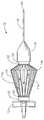
도 1은 본원발명의 바람직한 실시예에 따른 미세 외과 수술용 기구의 사시도이다;1 is a perspective view of a microsurgical instrument in accordance with a preferred embodiment of the present invention;
도 2는 도 1의 미세 외과 수술용 기구의 평면도이다;2 is a top view of the microsurgical instrument of FIG. 1;
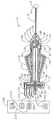
도 3은 미세 외과 수술용 시스템에 작동적으로 결합되어 도시된, 도 1의 미세 외과 수술용 기구의 측단면도이다;3 is a side cross-sectional view of the microsurgical instrument of FIG. 1, shown operatively coupled to the microsurgical system;
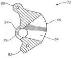
도 4는 도 1의 미세 외과 수술용 기구의 캠 부재의 확대된 사시도이다;4 is an enlarged perspective view of the cam member of the microsurgical instrument of FIG. 1;
도 5는 도 4의 캠 부재의 횡단면도이다;5 is a cross-sectional view of the cam member of FIG. 4;
도 6은 도 2의 원 내에 도시된 도 1의 미세 외과 수술용 기구의 일부에 대한 확대된 부분 측단면도이다;FIG. 6 is an enlarged partial cross-sectional side view of a portion of the microsurgical instrument of FIG. 1 shown in the circle of FIG. 2;
도 7은 도 1의 미세 외과 수술용 기구의 작동 메커니즘의 일부의 확대된 부분 측단면도이다.7 is an enlarged partial cross-sectional side view of a portion of the actuation mechanism of the microsurgical instrument of FIG. 1.
본원발명의 바람직한 실시예 및 그 장점이 도 1 내지 도 7을 참조하여 가장 잘 이해될 수 있으며, 여기서는 다양한 도면의 유사하고 상응하는 부분들에 대해서 는 유사한 도면부호가 사용되고 있다.Preferred embodiments of the present invention and their advantages can be best understood with reference to Figs. 1 to 7, wherein like reference numerals are used for similar and corresponding parts of the various figures.
미세 외과 수술용 기구(10)는 바람직하게, 기부(12), 작동용 핸들(14), 선단 부재(16), 말단 팁(distal tip)(20)을 갖는 절단 부재(18)를 포함한다. 도면에 도시된 바와 같이, 미세 외과 수술용 기구(10)는 유리체 절제술 탐침(vitrectomy probe)이다. 그러나 미세 외과 수술용 기구(10)는 어떠한 미세 외과 수술용 절단기, 흡입기, 또는 주입 탐침도 될 수 있다.The
기부(12)는 왕복운동 방식으로 절단 부재(18)의 관형 내부 절단 부재(110)를 작동시키기 위하여 작동 메커니즘(13)을 포함한다. 작동 메커니즘(13)은 바람직하게 제1 압축 공기 포트(22), 제2 압축 공기 포트(24), 격막 챔버(26), 가요성 격막(28), 및 강성의 중심 지지부(30)를 포함한다. 가요성 격막(28)은 기부(12) 및 중심 지지부(30)에 결합된다. 도면에 도시된 바와 같이, 가요성 격막(28)은 기부(12) 및 중심 지지부(30) 모두에 마찰에 의해 결합된다. 대안적으로, 가요성 격막(28)은 기부(28)에 마찰에 의해 결합되고 중심 지지부(30) 상에 오버몰드(over-mold) 될 수 있다. 중심 지지부(30)는 격막 챔버(26)의 벽 부분(33a) 및 (33b) 각각과 인터페이스를 이루기 위한 제한 표면(31a) 및 (31b)을 갖는다. 기부(12)는 또한 말단 팁(12c) 및 개구(12b)를 갖는 말단부(12a) 및 흡기 포트(34)를 포함한다. 칼라(36)는 말단부(12a)를 핸들(14)과 결합시킨다. 내부 절단 부재(110)는 중심 지지부(30)에 결합되며, O-링(38)을 통하여 슬라이딩 방식 및 유체 소통 방식으로(slidably and fluidly) 기부(12)에 결합된다.The
작동용 핸들(14)은 바람직하게 선단 기부(proximal base)(50), 말단 기 부(distal base)(52), 및 양 기부(50) 및 (52)에 결합되는 다수의 가요성 부속물(appendages)(14a)을 포함한다. 가요성 부속물(14a)은 티타늄, 스테인리스 스틸, 또는 적절한 열 가소성 물질과 같이, 임의의, 복원력을 갖는 적절한 탄성 물질로 제조될 수 있다. 핸들(14)은 기부(12)의 말단 부분(12a)을 둘러싼다. 선단 기부(50)는 칼라(36)에 결합된다. 말단 기부(52)는 슬라이딩 가능한 칼라(54) 내에 수용된다. 사용자는 핸들(14)을 통해 미세 외과 수술용 기구(10)를 움켜쥔다. 사용자가 가요성 부속물(14a) 상에 내부로 향하는 압력을 가하면, 가요성 부속물(14a)은 (14b)에서 또는 (14b) 부근에서 구부러져, 가요성 부속물(14a)이 펴지고 신장되며, 칼라(54)를 말단 기부(52) 쪽으로 이동시키게 된다. 이러한 압력이 제거되면, 스프링(55)이 가요성 부속물(14a)을 도 2에 도시된 위치로 복귀시킨다.The operating
선단 부재(16)는 바람직하게 캠 부재(72)를 수용하기 위한 캠 챔버(70), 기부(12)의 말단 팁(12c)을 수용하기 위한 기부 챔버(74), 절단 부재(18)의 내부 절단 부재(110)를 수용하기 위한 부싱(bushing)(76), 및 절단 부재(18)의 관형 외부 절단 부재(100)를 수용하기 위한 출구부(78)를 포함한다. 캠 부재(72)는 구멍(79)의 각 단부에 삽입되는 맞춤 핀(dowel pin)(도시되지 않음)을 통하여 기부(12)의 개구(12b) 내에서 선단 부재(16)에 회전식으로 결합된다. 캠 부재(72)는 칼라(54)와 접속하기 위한 제1 정지 표면(80), 기부(12)와 접속하기 위한 제2 정지 표면(82), 절단 부재(18)의 내부 절단 부재(110)를 수용하기 위한 슬롯(clearance slot)(84), 그리고 부싱(76)과 접속하기 위한 캠 표면(86)을 바람직하게 구비한다. O-링(88)은 선단 부재(16)를 내부 절단 부재(110)에 대해 슬라이딩 방식 및 유체 소통 방식으로 밀봉한다.The
앞서 기술된 바와 같이, 절단 부재(18)는 바람직하게 관형 외부 절단 부재(100) 및 관형 내부 절단 부재(110)를 포함한다. 외부 절단 부재(100)는 내부 구멍(102), 폐쇄 단부(104), 조직을 수용하기 위한 포트(106), 및 절단 표면(108)을 갖는다. 내부 절단 부재(110)는 내부 구멍(112), 개방 단부(114), 및 절단 표면(116)을 갖는다.As described above, the cutting
작동에 있어서, 유리체 절제술 탐침(10)은 미세 외과 수술용 시스템(198)에 작동적으로 결합된다. 더욱 구체적으로, 압축 공기 포트(22)는 유체 라인(202)을 통해 압축 공기 압력원(200)에 유체 소통 방식으로 결합되며, 압축 공기 포트(24)는 유체 라인(206)을 통해 압축 공기 압력원(204)에 유체 소통 방식으로 결합되며, 흡기 포트(34)는 유체 라인(209)을 통해 진공원(208)에 유체 소통 방식으로 결합된다. 내부 구멍(112) 및 유체 라인(209)에는 외과 수술상의 유체(surgical fluid)가 주입된다. 미세 외과 수술용 시스템(198)은 또한 마이크로 프로세서 또는 컴퓨터(210)도 구비하는데, 이는 각각 인터페이스(212) 및 (214)를 통하여 압축 공기 압력원(200) 및 (204)에 전기적으로 결합된다.In operation, the
외과의사는 평면 부분 삽입물(pars plana insertion)을 사용하여 눈의 후방 부분(posterior segment)으로 말단 팁(20)을 삽입한다. 외과의사는 진공원(208)에 대해 요구되는 진공도(vacuum level)를 선택한다. 포트(106)를 통해 내부 구멍(112)으로 조직이 흡입된다. 외과 의사는 마이크로 프로세서(210)를 사용하여, 그리고 선택적으로, 풋 제어기(foot controller)와 같은, 비례 제어 장치(도시되지 않음)를 사용하여 탐침(10)에 대하여 요구되는 절단 속도를 선택한다. 더욱 구체적으로, 마이크로 프로세서(210)는 격막(28)을 가로질러 주기적인 압력차를 형성하도록 가압된 가스 공급원(200) 및 (204)를 사용하여, 원하는 절단 속도로 왕복 이동하는 방식으로, 중심 지지부(30)를 이동시키고, 이에 따라 내부 절단 부재(110)를 이동시킨다. 압축 공기 포트(22)에 제공되는 압력이 압축 공기 포트(24)에 제공되는 압력보다 더 큰 경우에, 내부 절단 부재(110)는 개방 단부(114)가 도 6에 도시된 바와 같이 절단 표면(108)을 지나치게 될 때까지 말단 팁(20)을 향해 이동된다. 이러한 작동은 포트(106)를 폐쇄하여, 절단 표면(108) 및 (116)이 내부 구멍(112) 안쪽으로 조직을 잘라내도록 한다. 절단된 조직은 내부 구멍(112), 흡기 포트(34), 유체 라인(209)을 통하여 수집 챔버(도시되지 않음)로 흡입된다. 압축 공기 포트(24)에 제공되는 압력이 압축 공기 포트(22)에 제공되는 압력보다 크게 되면, 내부 절단 부재(110)는 말단 팁(20)으로부터 멀어지게 이동하여, 포트(106)를 개방하여 조직의 추가 흡입이 가능하게 한다.The surgeon inserts the
내부 절단 부재(110)의 작동 동안에, 절단 행정을 정확하게 종료시키기 위하여 중심 지지부(30)의 제한 표면(31a)이 격막 챔버(26)의 벽 부분(33a)과 접촉한다. 복귀 행정을 정확하게 종료시키기 위하여 중심 지지부(30)의 제한 표면(31b)이 격막 챔버(26)의 벽 부분(33b)과 접촉한다. 제한 표면(31a)이 벽 부분(33a)과 접촉하면, 내부 절단 부재(110)의 개방 단부(114)의 절단 표면(116)이 바람직하게 외부 절단 부재(100)의 말단 절단 표면(108)에 또는 이를 바로 지나쳐서 배치된다. 제한 표면(31b)이 벽 부분(33b)과 접촉하면, 개방 단부(114)가 바람직하게 외부 절 단 부재(100)의 선단 절단 표면(108)에 또는 그 부근에 배치된다. 내부 절단 부재(110) 작동의 이러한 정확한 제어는 탐침(10)의 절단 효율을 크게 향상시킨다.During operation of the
이상으로부터, 본원발명이 종래의 유리체 절제술 탐침에 비하여 상당한 이점을 제공한다는 것을 알 수 있다. 본 명세서에서 본원발명은 실시예를 통해 설명되었으나, 본원발명이 속하는 기술분야에서 통상의 지식을 가진 사람에 의해 다양한 수정이 이루어질 수 있다. 예를 들면, 이상에서는 본원발명이 유리체 절제술 탐침과 관련하여 설명되었으나, 흡기용 탐침(aspiration probe), 주입용 탐침(infusion probe), 및 기타의 절단용 탐침에도 동일하게 적용될 수 있다.From the above, it can be seen that the present invention provides a significant advantage over the conventional vitrectomy probe. Although the present invention has been described herein through examples, various modifications may be made by a person having ordinary skill in the art to which the present invention belongs. For example, while the present invention has been described in connection with a vitrectomy probe, the same may be applied to an inspiration probe, an infusion probe, and other cutting probes.
본원발명의 작동 및 구성은 이상의 설명으로부터 명백할 것이다. 이상에서 설명되거나 도시된 장치 및 방법이 바람직한 것으로 기술되었으나, 이하의 청구범위에서 한정되는 바와 같이 본원발명의 범위나 사상 내에서 다양한 변경이나 수정이 이루어질 수 있다.The operation and construction of the present invention will be apparent from the above description. Although the apparatus and method described or illustrated above have been described as being preferred, various changes or modifications may be made within the scope or spirit of the invention as defined in the following claims.
Claims (4)
Translated fromKoreanApplications Claiming Priority (3)
| Application Number | Priority Date | Filing Date | Title |
|---|---|---|---|
| US11/348,118US8187293B2 (en) | 2006-02-06 | 2006-02-06 | Microsurgical instrument |
| US11/348,118 | 2006-02-06 | ||
| PCT/US2007/061476WO2007092739A2 (en) | 2006-02-06 | 2007-02-01 | Microsurgical instrument |
Publications (2)
| Publication Number | Publication Date |
|---|---|
| KR20080091516Atrue KR20080091516A (en) | 2008-10-13 |
| KR101324145B1 KR101324145B1 (en) | 2013-11-01 |
Family
ID=38335009
Family Applications (1)
| Application Number | Title | Priority Date | Filing Date |
|---|---|---|---|
| KR1020087021825AActiveKR101324145B1 (en) | 2006-02-06 | 2007-02-01 | Microsurgical instrument |
Country Status (18)
| Country | Link |
|---|---|
| US (1) | US8187293B2 (en) |
| EP (1) | EP1981416B1 (en) |
| JP (1) | JP5296556B2 (en) |
| KR (1) | KR101324145B1 (en) |
| CN (1) | CN101378703B (en) |
| AT (1) | ATE492225T1 (en) |
| AU (1) | AU2007212114B2 (en) |
| BR (1) | BRPI0707392B8 (en) |
| CA (1) | CA2637816C (en) |
| CY (1) | CY1111329T1 (en) |
| DE (1) | DE602007011395D1 (en) |
| DK (1) | DK1981416T3 (en) |
| ES (1) | ES2356785T3 (en) |
| PL (1) | PL1981416T3 (en) |
| PT (1) | PT1981416E (en) |
| RU (1) | RU2432929C2 (en) |
| SI (1) | SI1981416T1 (en) |
| WO (1) | WO2007092739A2 (en) |
Families Citing this family (53)
| Publication number | Priority date | Publication date | Assignee | Title |
|---|---|---|---|---|
| PL2094173T3 (en) | 2006-12-21 | 2016-09-30 | Disposable vitrectomy handpiece | |
| US8568391B2 (en) | 2007-04-20 | 2013-10-29 | Doheny Eye Institute | Sterile surgical tray |
| CN101765414B (en) | 2007-04-20 | 2013-09-25 | 多汉尼眼科研究所 | Independent surgical center |
| US8080029B2 (en)* | 2007-09-21 | 2011-12-20 | Novartis Ag | System for actuation of a vitreous cutter |
| EP3272298A1 (en)* | 2007-09-27 | 2018-01-24 | Doheny Eye Institute | Selectable stroke cutter |
| JP5770731B2 (en) | 2009-08-31 | 2015-08-26 | アルコン リサーチ, リミテッド | Control of pneumatic output by drive valve duty |
| ES2442368T3 (en)* | 2009-12-10 | 2014-02-11 | Alcon Research, Ltd. | Systems and procedures for dynamic pneumatic valve actuator |
| US8666556B2 (en)* | 2009-12-10 | 2014-03-04 | Alcon Research, Ltd. | Systems and methods for dynamic feedforward |
| US8821524B2 (en) | 2010-05-27 | 2014-09-02 | Alcon Research, Ltd. | Feedback control of on/off pneumatic actuators |
| US8579887B2 (en) | 2010-11-09 | 2013-11-12 | Synergetics Usa, Inc. | Axially reciprocating microsurgical instrument with radially compressed actuator handle |
| US8888802B2 (en) | 2010-12-21 | 2014-11-18 | Alcon Research, Ltd. | Vitrectomy probe with adjustable cutter port size |
| US9101441B2 (en) | 2010-12-21 | 2015-08-11 | Alcon Research, Ltd. | Vitrectomy probe with adjustable cutter port size |
| US8540743B2 (en)* | 2010-12-22 | 2013-09-24 | Alcon Research, Ltd. | Hydraulic vitrectomy probe |
| US10874552B2 (en) | 2011-07-08 | 2020-12-29 | Doheny Eye Institute | Ocular lens cutting device |
| CN102327159B (en)* | 2011-08-18 | 2013-05-15 | 杨勋 | Dual purpose vitreous body cutting head |
| US9060841B2 (en) | 2011-08-31 | 2015-06-23 | Alcon Research, Ltd. | Enhanced flow vitrectomy probe |
| US10070990B2 (en) | 2011-12-08 | 2018-09-11 | Alcon Research, Ltd. | Optimized pneumatic drive lines |
| US9517161B2 (en) | 2011-12-20 | 2016-12-13 | Alcon Research, Ltd. | Vitrectomy probe with adjustable cutter port size |
| US9629748B2 (en)* | 2012-05-31 | 2017-04-25 | Medical Instrument Development Laboratories, Inc. | Multi-stage tubing for high-speed pneumatic surgical cutter |
| US9924963B2 (en) | 2012-12-13 | 2018-03-27 | Novartis Ag | Vitrectomy probe with integral valve |
| US9615969B2 (en) | 2012-12-18 | 2017-04-11 | Novartis Ag | Multi-port vitrectomy probe with dual cutting edges |
| EP2913035A1 (en)* | 2014-02-27 | 2015-09-02 | EOS GmbH | Ophthalmic surgery device with a surgical handpiece and controls for controlling the stroke of the hollow needle |
| RU2554230C1 (en)* | 2014-06-09 | 2015-06-27 | федеральное государственное бюджетное учреждение "Межотраслевой научно-технический комплекс "Микрохирургия глаза" имени академика С.Н. Федорова" Министерства здравоохранения Российской Федерации | Method of carrying out vitrectomy in surgical treatment of retinal detachment, complicated with proliferative vitreoretinopathy |
| EP3185803B1 (en)* | 2014-08-25 | 2020-06-03 | Peregrine Surgical, Ltd. | Microsurgical instrument |
| US9693898B2 (en) | 2014-11-19 | 2017-07-04 | Novartis Ag | Double-acting vitreous probe with contoured port |
| DE102014118575B4 (en) | 2014-12-12 | 2016-10-06 | Carl Zeiss Meditec Ag | Surgical instrument |
| JP6760961B2 (en) | 2015-04-13 | 2020-09-23 | アルコン インコーポレイティド | High speed pneumatic valve |
| CN105310821A (en)* | 2015-05-15 | 2016-02-10 | 以诺康医疗科技(苏州)有限公司 | Ultrasonic vitrectomy needle and device thereof |
| CN105476744B (en)* | 2016-02-23 | 2017-10-31 | 首都医科大学附属北京朝阳医院 | A kind of anterior vitreous cutter device |
| US10729582B2 (en) | 2016-05-17 | 2020-08-04 | Alcon Inc. | Vitrectomy probe with end tissue cutter and associated devices, systems, and methods |
| CA3048961A1 (en) | 2017-02-27 | 2018-08-30 | Novartis Ag | Reciprocating surgical tool with inertial damper |
| US11278450B2 (en) | 2017-05-04 | 2022-03-22 | Carl Zeiss Meditec Cataract Technology Inc. | Devices and methods for ocular surgery |
| US10639197B2 (en)* | 2017-06-19 | 2020-05-05 | Alcon Inc. | Vitrectomy probe |
| US10893978B2 (en) | 2017-12-14 | 2021-01-19 | Alcon Inc. | Vitreous cutter pneumatic driver |
| KR102782862B1 (en) | 2018-06-05 | 2025-03-19 | 칼 짜이스 메디텍 캐터랙트 테크놀로지 인크. | Ophthalmic Microsurgical Instruments, Systems and Methods of Use |
| EP3790518B1 (en) | 2018-07-13 | 2023-08-16 | Alcon Inc. | Vitrectomy instrument with precision cutter stop |
| EP3860535B1 (en) | 2018-12-12 | 2024-08-14 | Alcon Inc. | Actuation handle |
| JP7434340B2 (en) | 2019-02-01 | 2024-02-20 | カール・ツァイス・メディテック・キャタラクト・テクノロジー・インコーポレイテッド | Ophthalmic cutting instrument with integrated suction pump |
| WO2020157617A1 (en) | 2019-02-01 | 2020-08-06 | Alcon Inc. | Actuation mechanism with arcuate levers |
| KR20220010739A (en) | 2019-05-17 | 2022-01-26 | 칼 짜이스 메디텍 캐터랙트 테크놀로지 인크. | Ophthalmic Cutting Instrument with Integral Suction Pump |
| CA3142864A1 (en) | 2019-06-07 | 2020-12-10 | Carl Zeiss Meditec Cataract Technology Inc. | Multi-stage trigger for ophthalmology cutting tool |
| USD934424S1 (en) | 2019-08-29 | 2021-10-26 | Alcon Inc. | 360 degree actuation handle |
| WO2021038428A1 (en) | 2019-08-29 | 2021-03-04 | Alcon Inc. | Actuation mechanism with grooved actuation levers |
| WO2021053467A1 (en) | 2019-09-16 | 2021-03-25 | Alcon Inc. | Reduced vibration vitrectomy probe |
| BR112022011125A2 (en) | 2019-12-11 | 2022-08-23 | Alcon Inc | ADJUSTABLE REINFORCEMENT FOR SURGICAL INSTRUMENTS |
| US11540941B2 (en) | 2019-12-11 | 2023-01-03 | Alcon Inc. | Adjustable support sleeve for surgical instruments |
| JP7725578B2 (en) | 2020-10-07 | 2025-08-19 | アルコン インコーポレイティド | Multi-Diaphragm Vitreous Surgery Probe |
| US12059373B2 (en)* | 2020-11-20 | 2024-08-13 | Alcon Inc. | Fluid driven vitrectomy probe |
| WO2022150837A1 (en)* | 2021-01-08 | 2022-07-14 | Sonex Health, Inc. | Surgical cutting device for ultrasonic guided soft tissue surgery |
| CN114748241A (en)* | 2021-01-09 | 2022-07-15 | 深圳市眼科医院 | Intraocular forceps with membrane separation mechanism |
| US20220347015A1 (en)* | 2021-05-03 | 2022-11-03 | VisionCare Devices LLC. | Vitrector Cutting Device with Distal Illumination Module |
| US12186236B2 (en) | 2021-08-26 | 2025-01-07 | Alcon Inc. | Adjustable stiffener for surgical instruments |
| DE102022107857A1 (en)* | 2022-04-01 | 2023-10-05 | Tuebingen Scientific Medical Gmbh | Pneumatic drive device for translational and/or rotational movement |
Family Cites Families (51)
| Publication number | Priority date | Publication date | Assignee | Title |
|---|---|---|---|---|
| US3884238A (en)* | 1972-06-19 | 1975-05-20 | Malley Conor C O | Apparatus for intraocular surgery |
| US4493698A (en)* | 1980-11-03 | 1985-01-15 | Cooper Medical Devices | Method of performing opthalmic surgery utilizing a linear intra-ocular suction device |
| US4449550A (en)* | 1981-11-02 | 1984-05-22 | Optikon Oftalmologia, S.P.A. | Control system for intraocular surgical device |
| US4577629A (en)* | 1983-10-28 | 1986-03-25 | Coopervision, Inc. | Surgical cutting instrument for ophthalmic surgery |
| US4757814A (en)* | 1985-02-28 | 1988-07-19 | Alcon Laboratories, Inc. | Proportional control for pneumatic cutting device |
| US4841984A (en)* | 1985-09-16 | 1989-06-27 | Armoor Ophthalmics, Inc. | Fluid-carrying components of apparatus for automatic control of intraocular pressure |
| US4768506A (en)* | 1985-09-26 | 1988-09-06 | Alcon Laboratories, Inc. | Handpiece drive apparatus for powered surgical scissors |
| US5020535A (en)* | 1985-09-26 | 1991-06-04 | Alcon Laboratories, Inc. | Handpiece drive apparatus for powered surgical scissors |
| US4696298A (en)* | 1985-11-19 | 1987-09-29 | Storz Instrument Company | Vitrectomy cutting mechanism |
| JPS63279843A (en)* | 1987-05-13 | 1988-11-16 | Tokyo Optical Co Ltd | Operating cutter |
| JPH0350894Y2 (en)* | 1987-05-13 | 1991-10-30 | ||
| US4819635A (en)* | 1987-09-18 | 1989-04-11 | Henry Shapiro | Tubular microsurgery cutting apparatus |
| US4986827A (en)* | 1987-11-05 | 1991-01-22 | Nestle S.A. | Surgical cutting instrument with reciprocating inner cutter |
| US4909249A (en)* | 1987-11-05 | 1990-03-20 | The Cooper Companies, Inc. | Surgical cutting instrument |
| US4940468A (en)* | 1988-01-13 | 1990-07-10 | Petillo Phillip J | Apparatus for microsurgery |
| US5024652A (en)* | 1988-09-23 | 1991-06-18 | Dumenek Vladimir A | Ophthalmological device |
| US5061238A (en)* | 1989-02-23 | 1991-10-29 | Linvatec Corporation | Surgical cutting instrument with titanium nitride coating on an inner tubular member |
| US5019035A (en)* | 1989-06-07 | 1991-05-28 | Alcon Surgical, Inc. | Cutting assembly for surgical cutting instrument |
| US5226910A (en)* | 1989-07-05 | 1993-07-13 | Kabushiki Kaisha Topcon | Surgical cutter |
| JPH0337059A (en)* | 1989-07-05 | 1991-02-18 | Topcon Corp | surgical cutter |
| US5106364A (en)* | 1989-07-07 | 1992-04-21 | Kabushiki Kaisha Topcon | Surgical cutter |
| JPH0339158A (en)* | 1989-07-07 | 1991-02-20 | Topcon Corp | surgical cutter |
| US5059204A (en)* | 1989-10-26 | 1991-10-22 | Site Microsurgical Systems, Inc. | Ocular cutter with enhanced cutting action |
| US5176628A (en)* | 1989-10-27 | 1993-01-05 | Alcon Surgical, Inc. | Vitreous cutter |
| US5047008A (en)* | 1989-10-27 | 1991-09-10 | Storz Instrument Company | Vitrectomy probe |
| JP3218064B2 (en)* | 1991-12-04 | 2001-10-15 | 株式会社トプコン | Surgical equipment |
| US5284472A (en)* | 1992-10-30 | 1994-02-08 | Allergan, Inc. | Vitreous cutter |
| US5354268A (en)* | 1992-11-04 | 1994-10-11 | Medical Instrument Development Laboratories, Inc. | Methods and apparatus for control of vacuum and pressure for surgical procedures |
| AU6667494A (en)* | 1993-05-07 | 1994-12-12 | Danek Medical, Inc. | Surgical cutting instrument |
| US5423844A (en)* | 1993-10-22 | 1995-06-13 | Promex, Inc. | Rotary surgical cutting instrument |
| US5380280A (en)* | 1993-11-12 | 1995-01-10 | Peterson; Erik W. | Aspiration system having pressure-controlled and flow-controlled modes |
| US6188869B1 (en)* | 1994-04-07 | 2001-02-13 | Hark C. Chan | Information distribution and processing system |
| US5520852A (en)* | 1994-06-08 | 1996-05-28 | Neste Oy | Processible electrically conducting polyaniline compositions |
| US5474532A (en)* | 1994-11-22 | 1995-12-12 | Alcon Laboratories, Inc. | Cutting blade for a vitreous cutter |
| US5630827A (en)* | 1995-06-19 | 1997-05-20 | Dutch Ophthalmic Research Center International Bv | Vitreous removing apparatus |
| US5674194A (en)* | 1995-10-25 | 1997-10-07 | Alcon Laboratories Inc. | Process control system |
| US5669923A (en)* | 1996-01-24 | 1997-09-23 | Gordon; Mark G. | Anterior capsulotomy device and procedure |
| US5833643A (en)* | 1996-06-07 | 1998-11-10 | Scieran Technologies, Inc. | Apparatus for performing ophthalmic procedures |
| US6010496A (en)* | 1996-08-29 | 2000-01-04 | Bausch & Lomb Surgical, Inc. | Vitrectomy timing device with microcontroller with programmable timers |
| US5733297A (en)* | 1996-09-10 | 1998-03-31 | Medical Instrument Development Laboratories, Inc. | Cutter for surgical probe |
| DE19719549C2 (en)* | 1997-05-09 | 1999-10-14 | Joachim Schoen | Ophthalmic surgical instrument for opening the front lens capsule |
| US6592541B1 (en)* | 1998-07-21 | 2003-07-15 | Badrudin Kurwa | Ophthalmological surgical instrument, device and method of use |
| CN1260161A (en)* | 1999-01-10 | 2000-07-19 | 姜宪委 | Surgical instrument for tissue excision and system for using said instrument |
| US6704929B1 (en)* | 1999-08-18 | 2004-03-09 | Webtv Networks, Inc. | Tracking viewing behavior of a home entertainment system |
| US6514268B2 (en)* | 1999-08-30 | 2003-02-04 | Alcon Universal Ltd. | Method of operating microsurgical instruments |
| JP2001087303A (en)* | 1999-09-27 | 2001-04-03 | Nidek Co Ltd | Ophthalmic surgery apparatus |
| US7051352B1 (en)* | 2000-02-04 | 2006-05-23 | Koninklijke Philips Electronics N.V. | Adaptive TV program recommender |
| US6488695B1 (en)* | 2000-08-17 | 2002-12-03 | Alcon, Inc. | Ophthalmologic surgical probe |
| RU2240091C1 (en)* | 2003-07-15 | 2004-11-20 | Московский научно-исследовательский институт глазных болезней им. Гельмгольца | Ophthalmosurgical instrument |
| RU2262332C2 (en)* | 2003-12-17 | 2005-10-20 | Государственное учреждение Межотраслевой научно-технический комплекс "Микрохирургия глаза" им. акад. С.Н. Федорова | Device for perforating sclera in performing vitrectomy |
| CN2706133Y (en)* | 2004-05-13 | 2005-06-29 | 张宏文 | Antidromic naso lacrymal duct drill cutter |
- 2006
- 2006-02-06USUS11/348,118patent/US8187293B2/enactiveActive
- 2007
- 2007-02-01WOPCT/US2007/061476patent/WO2007092739A2/enactiveApplication Filing
- 2007-02-01DEDE602007011395Tpatent/DE602007011395D1/enactiveActive
- 2007-02-01PTPT07763558Tpatent/PT1981416E/enunknown
- 2007-02-01CNCN2007800046728Apatent/CN101378703B/enactiveActive
- 2007-02-01RURU2008135997/14Apatent/RU2432929C2/enactive
- 2007-02-01BRBRPI0707392Apatent/BRPI0707392B8/enactiveIP Right Grant
- 2007-02-01AUAU2007212114Apatent/AU2007212114B2/enactiveActive
- 2007-02-01EPEP07763558Apatent/EP1981416B1/enactiveActive
- 2007-02-01JPJP2008553507Apatent/JP5296556B2/enactiveActive
- 2007-02-01KRKR1020087021825Apatent/KR101324145B1/enactiveActive
- 2007-02-01DKDK07763558.9Tpatent/DK1981416T3/enactive
- 2007-02-01PLPL07763558Tpatent/PL1981416T3/enunknown
- 2007-02-01CACA2637816Apatent/CA2637816C/enactiveActive
- 2007-02-01ATAT07763558Tpatent/ATE492225T1/enactive
- 2007-02-01SISI200730521Tpatent/SI1981416T1/enunknown
- 2007-02-01ESES07763558Tpatent/ES2356785T3/enactiveActive
- 2011
- 2011-03-11CYCY20111100276Tpatent/CY1111329T1/enunknown
Also Published As
| Publication number | Publication date |
|---|---|
| RU2432929C2 (en) | 2011-11-10 |
| CA2637816C (en) | 2014-03-18 |
| RU2008135997A (en) | 2010-03-20 |
| DE602007011395D1 (en) | 2011-02-03 |
| ATE492225T1 (en) | 2011-01-15 |
| CN101378703A (en) | 2009-03-04 |
| AU2007212114B2 (en) | 2012-12-20 |
| BRPI0707392A2 (en) | 2011-05-03 |
| CA2637816A1 (en) | 2007-08-16 |
| BRPI0707392B8 (en) | 2021-06-22 |
| PL1981416T3 (en) | 2011-08-31 |
| ES2356785T3 (en) | 2011-04-13 |
| AU2007212114A1 (en) | 2007-08-16 |
| EP1981416B1 (en) | 2010-12-22 |
| CN101378703B (en) | 2011-03-23 |
| US8187293B2 (en) | 2012-05-29 |
| PT1981416E (en) | 2011-02-23 |
| JP5296556B2 (en) | 2013-09-25 |
| DK1981416T3 (en) | 2011-02-14 |
| BRPI0707392B1 (en) | 2018-05-02 |
| JP2009525783A (en) | 2009-07-16 |
| KR101324145B1 (en) | 2013-11-01 |
| EP1981416A4 (en) | 2009-05-27 |
| US20070185512A1 (en) | 2007-08-09 |
| WO2007092739A2 (en) | 2007-08-16 |
| EP1981416A2 (en) | 2008-10-22 |
| WO2007092739A3 (en) | 2007-12-06 |
| CY1111329T1 (en) | 2015-08-05 |
| SI1981416T1 (en) | 2011-04-29 |
Similar Documents
| Publication | Publication Date | Title |
|---|---|---|
| KR101324145B1 (en) | Microsurgical instrument | |
| KR101192506B1 (en) | Modular design for ophthalmic surgical probe | |
| US20070185514A1 (en) | Microsurgical instrument | |
| US7285107B1 (en) | Vitreoretinal instrument | |
| US20100312169A1 (en) | Method of operating a vitrectomy probe | |
| US20080172078A1 (en) | Reduced traction vitrectomy probe | |
| JP2010508073A5 (en) | ||
| JP2021529624A (en) | Vitreous excision instrument with precision cutter stop | |
| WO2018138592A1 (en) | Vacuum control for a vitrectomy probe |
Legal Events
| Date | Code | Title | Description |
|---|---|---|---|
| PA0105 | International application | Patent event date:20080905 Patent event code:PA01051R01D Comment text:International Patent Application | |
| PG1501 | Laying open of application | ||
| A201 | Request for examination | ||
| PA0201 | Request for examination | Patent event code:PA02012R01D Patent event date:20120201 Comment text:Request for Examination of Application | |
| E902 | Notification of reason for refusal | ||
| PE0902 | Notice of grounds for rejection | Comment text:Notification of reason for refusal Patent event date:20130418 Patent event code:PE09021S01D | |
| E701 | Decision to grant or registration of patent right | ||
| PE0701 | Decision of registration | Patent event code:PE07011S01D Comment text:Decision to Grant Registration Patent event date:20130923 | |
| GRNT | Written decision to grant | ||
| PR0701 | Registration of establishment | Comment text:Registration of Establishment Patent event date:20131025 Patent event code:PR07011E01D | |
| PR1002 | Payment of registration fee | Payment date:20131028 End annual number:3 Start annual number:1 | |
| PG1601 | Publication of registration | ||
| FPAY | Annual fee payment | Payment date:20160929 Year of fee payment:4 | |
| PR1001 | Payment of annual fee | Payment date:20160929 Start annual number:4 End annual number:4 | |
| PR1001 | Payment of annual fee | Payment date:20220929 Start annual number:10 End annual number:10 | |
| PR1001 | Payment of annual fee | Payment date:20231004 Start annual number:11 End annual number:11 | |
| PR1001 | Payment of annual fee | Payment date:20240927 Start annual number:12 End annual number:12 |