KR20080091186A - Fitting for tube or pipe - Google Patents
Fitting for tube or pipeDownload PDFInfo
- Publication number
- KR20080091186A KR20080091186AKR1020087018915AKR20087018915AKR20080091186AKR 20080091186 AKR20080091186 AKR 20080091186AKR 1020087018915 AKR1020087018915 AKR 1020087018915AKR 20087018915 AKR20087018915 AKR 20087018915AKR 20080091186 AKR20080091186 AKR 20080091186A
- Authority
- KR
- South Korea
- Prior art keywords
- tube
- fitting
- tapered
- wall
- component
- Prior art date
- Legal status (The legal status is an assumption and is not a legal conclusion. Google has not performed a legal analysis and makes no representation as to the accuracy of the status listed.)
- Withdrawn
Links
- 238000006243chemical reactionMethods0.000claimsdescription60
- 238000000926separation methodMethods0.000claimsdescription18
- 230000006835compressionEffects0.000claimsdescription13
- 238000007906compressionMethods0.000claimsdescription13
- 238000009434installationMethods0.000claimsdescription8
- 241000699666Mus <mouse, genus>Species0.000description17
- 238000005452bendingMethods0.000description12
- 238000006073displacement reactionMethods0.000description6
- 239000012530fluidSubstances0.000description6
- 238000000034methodMethods0.000description4
- 230000009471actionEffects0.000description2
- 230000000712assemblyEffects0.000description2
- 238000000429assemblyMethods0.000description2
- 230000008878couplingEffects0.000description2
- 238000010168coupling processMethods0.000description2
- 238000005859coupling reactionMethods0.000description2
- 239000000463materialSubstances0.000description2
- 230000009467reductionEffects0.000description2
- 238000007789sealingMethods0.000description2
- 229910001220stainless steelInorganic materials0.000description2
- 239000010935stainless steelSubstances0.000description2
- 230000007704transitionEffects0.000description2
- 241000699670Mus sp.Species0.000description1
- 230000004323axial lengthEffects0.000description1
- 230000008030eliminationEffects0.000description1
- 238000003379elimination reactionMethods0.000description1
- 239000004615ingredientSubstances0.000description1
- 230000004048modificationEffects0.000description1
- 238000012986modificationMethods0.000description1
- 230000008569processEffects0.000description1
Images


Classifications
- F—MECHANICAL ENGINEERING; LIGHTING; HEATING; WEAPONS; BLASTING
- F16—ENGINEERING ELEMENTS AND UNITS; GENERAL MEASURES FOR PRODUCING AND MAINTAINING EFFECTIVE FUNCTIONING OF MACHINES OR INSTALLATIONS; THERMAL INSULATION IN GENERAL
- F16L—PIPES; JOINTS OR FITTINGS FOR PIPES; SUPPORTS FOR PIPES, CABLES OR PROTECTIVE TUBING; MEANS FOR THERMAL INSULATION IN GENERAL
- F16L47/00—Connecting arrangements or other fittings specially adapted to be made of plastics or to be used with pipes made of plastics
- F16L47/06—Connecting arrangements or other fittings specially adapted to be made of plastics or to be used with pipes made of plastics with sleeve or socket formed by or in the pipe end
- F16L47/08—Connecting arrangements or other fittings specially adapted to be made of plastics or to be used with pipes made of plastics with sleeve or socket formed by or in the pipe end with sealing rings arranged between the outer surface of one pipe end and the inner surface of the sleeve or socket, the sealing rings being placed previously in the sleeve or socket
- F—MECHANICAL ENGINEERING; LIGHTING; HEATING; WEAPONS; BLASTING
- F16—ENGINEERING ELEMENTS AND UNITS; GENERAL MEASURES FOR PRODUCING AND MAINTAINING EFFECTIVE FUNCTIONING OF MACHINES OR INSTALLATIONS; THERMAL INSULATION IN GENERAL
- F16L—PIPES; JOINTS OR FITTINGS FOR PIPES; SUPPORTS FOR PIPES, CABLES OR PROTECTIVE TUBING; MEANS FOR THERMAL INSULATION IN GENERAL
- F16L15/00—Screw-threaded joints; Forms of screw-threads for such joints
- F16L15/08—Screw-threaded joints; Forms of screw-threads for such joints with supplementary elements
- F—MECHANICAL ENGINEERING; LIGHTING; HEATING; WEAPONS; BLASTING
- F16—ENGINEERING ELEMENTS AND UNITS; GENERAL MEASURES FOR PRODUCING AND MAINTAINING EFFECTIVE FUNCTIONING OF MACHINES OR INSTALLATIONS; THERMAL INSULATION IN GENERAL
- F16L—PIPES; JOINTS OR FITTINGS FOR PIPES; SUPPORTS FOR PIPES, CABLES OR PROTECTIVE TUBING; MEANS FOR THERMAL INSULATION IN GENERAL
- F16L19/00—Joints in which sealing surfaces are pressed together by means of a member, e.g. a swivel nut, screwed on, or into, one of the joint parts
- F16L19/06—Joints in which sealing surfaces are pressed together by means of a member, e.g. a swivel nut, screwed on, or into, one of the joint parts in which radial clamping is obtained by wedging action on non-deformed pipe ends
- F16L19/061—Joints in which sealing surfaces are pressed together by means of a member, e.g. a swivel nut, screwed on, or into, one of the joint parts in which radial clamping is obtained by wedging action on non-deformed pipe ends a pressure ring being arranged between the clamping ring and the threaded member or the connecting member
- F—MECHANICAL ENGINEERING; LIGHTING; HEATING; WEAPONS; BLASTING
- F16—ENGINEERING ELEMENTS AND UNITS; GENERAL MEASURES FOR PRODUCING AND MAINTAINING EFFECTIVE FUNCTIONING OF MACHINES OR INSTALLATIONS; THERMAL INSULATION IN GENERAL
- F16L—PIPES; JOINTS OR FITTINGS FOR PIPES; SUPPORTS FOR PIPES, CABLES OR PROTECTIVE TUBING; MEANS FOR THERMAL INSULATION IN GENERAL
- F16L15/00—Screw-threaded joints; Forms of screw-threads for such joints
- F—MECHANICAL ENGINEERING; LIGHTING; HEATING; WEAPONS; BLASTING
- F16—ENGINEERING ELEMENTS AND UNITS; GENERAL MEASURES FOR PRODUCING AND MAINTAINING EFFECTIVE FUNCTIONING OF MACHINES OR INSTALLATIONS; THERMAL INSULATION IN GENERAL
- F16L—PIPES; JOINTS OR FITTINGS FOR PIPES; SUPPORTS FOR PIPES, CABLES OR PROTECTIVE TUBING; MEANS FOR THERMAL INSULATION IN GENERAL
- F16L19/00—Joints in which sealing surfaces are pressed together by means of a member, e.g. a swivel nut, screwed on, or into, one of the joint parts
- F16L19/08—Joints in which sealing surfaces are pressed together by means of a member, e.g. a swivel nut, screwed on, or into, one of the joint parts with metal rings which bite into the wall of the pipe
- F16L19/10—Joints in which sealing surfaces are pressed together by means of a member, e.g. a swivel nut, screwed on, or into, one of the joint parts with metal rings which bite into the wall of the pipe the profile of the ring being altered
- F16L19/103—Joints in which sealing surfaces are pressed together by means of a member, e.g. a swivel nut, screwed on, or into, one of the joint parts with metal rings which bite into the wall of the pipe the profile of the ring being altered with more than one ring per pipe end being used
- F—MECHANICAL ENGINEERING; LIGHTING; HEATING; WEAPONS; BLASTING
- F16—ENGINEERING ELEMENTS AND UNITS; GENERAL MEASURES FOR PRODUCING AND MAINTAINING EFFECTIVE FUNCTIONING OF MACHINES OR INSTALLATIONS; THERMAL INSULATION IN GENERAL
- F16L—PIPES; JOINTS OR FITTINGS FOR PIPES; SUPPORTS FOR PIPES, CABLES OR PROTECTIVE TUBING; MEANS FOR THERMAL INSULATION IN GENERAL
- F16L47/00—Connecting arrangements or other fittings specially adapted to be made of plastics or to be used with pipes made of plastics
Landscapes
- Engineering & Computer Science (AREA)
- General Engineering & Computer Science (AREA)
- Mechanical Engineering (AREA)
- Joints With Pressure Members (AREA)
- Quick-Acting Or Multi-Walled Pipe Joints (AREA)
- Joints With Sleeves (AREA)
- Insertion Pins And Rivets (AREA)
Abstract
Translated fromKoreanDescription
Translated fromKorean본 발명은 튜브 또는 파이프용 이음쇠에 관한 것이다.The present invention relates to fittings for tubes or pipes.
이음쇠는 튜브 또는 그 밖의 도관의 단부를 다른 부재에 결합 또는 연결시키는 데 사용될 수 있으며, 상기 다른 부재는, 예컨대 다른 T자형 관통 이음쇠 및 엘보우 이음쇠와 같은 다른 튜브나 도관 단부이거나, 또는 튜브 단부와 유체 소통할 것을 필요로 하는, 예컨대 밸브와 같은 장치이다. 한가지 타입의 이음쇠는 암나사형 구동 너트의 영향을 받아 튜브와 본체 사이에서의 시일 및 파지 작용을 제공하는 2개의 페룰(ferrule)을 포함하는 파지 구성을 이용한다. 다른 타입의 파지 장치를 사용하고 수나사형 구동 너트를 사용하는, 예컨대 단일 페룰 이음쇠와 같은 다른 타입의 이음쇠도 알려져 있다.The fittings can be used to join or connect the end of a tube or other conduit to another member, said other member being another tube or conduit end, such as other T-shaped through fittings and elbow fittings, or in fluid with the tube end. A device such as a valve, for example, that needs to communicate. One type of fitting utilizes a gripping configuration that includes two ferrules that provide a seal and gripping action between the tube and the body under the influence of a female threaded drive nut. Other types of fittings, such as single ferrule fittings, for example, using other types of gripping devices and using male threaded drive nuts are also known.
풀업(pull-up)시에 반경 방향으로 변위되거나 확대되는 튜브 이음쇠의 구성 요소는 풀업 변형 에너지의 일부를 흡수하고, 확대 또는 변위의 결과로서 반경 방향으로 인접 및/또는 반경 방향으로 근접한 이음쇠 구성 요소의 표면에 접촉할 수 있다. 예컨대, 2개 페룰 이음쇠의 전방 페룰 또는 단일 페룰을 포함하는 이음쇠의 페룰과 같은 튜브 파지 부재의 튜브 인보드는 이음쇠의 풀업시에 반경 방향 외측으로 확대될 수 있고, 풀업 변형 에너지의 일부를 흡수한다.Components of tube fittings that are radially displaced or enlarged upon pull-up absorb part of the pullup strain energy and are radially adjacent and / or radially close fitting components as a result of the enlargement or displacement. Can be in contact with the surface. For example, a tube inboard of a tube gripping member, such as a front ferrule of two ferrule fittings or a ferrule of a fitting comprising a single ferrule, may expand radially outwards upon pullup of the fitting and absorb some of the pullup strain energy.
본 출원은 일반적으로, 예컨대 이음쇠를 설치하는 동안의 이음쇠 구성 요소의 축방향 압박의 결과로서 이음쇠 구성 요소의 반경 방향 외측 이동으로 인해 결합 구성 요소들이 풀업 동안에 서로 접촉하는 경우, 그리고 이러한 때, 이음쇠의 해체중에 2개 이상의 이음쇠 구성 요소를 분리하는 것에 기여하도록 구성되는 이음쇠 조립체에 관한 것이다. 여기에서 사용되는 이음쇠 조립체의 이음쇠 구성 요소는, 예컨대 커플링 본체 및 밸브체와 같은 본체와, 구동 너트와, 예컨대 페룰과 같은 튜브 파지 부재와, 관 또는 다른 도관, 그리고 예컨대 튜브 파지 부재 설치 공구 또는 예비 스웨이징 공구와 같은 이음쇠 설치 공구를 포함할 수 있으며, 이들로 제한되지는 않는다.The present application generally relates to the case where the coupling components come into contact with one another during pull-up, for example due to the radially outward movement of the fitting component as a result of axial compression of the fitting component during installation of the fitting, and at this time, A fitting assembly configured to contribute to separating two or more fitting components during disassembly. The fitting components of the fitting assembly used here include, for example, a body such as a coupling body and a valve body, a drive nut and a tube gripping member such as a ferrule, a tube or other conduit, and a tube gripping member installation tool or Fitting installation tools, such as preliminary swaging tools, may be included, but are not limited to these.
본 발명의 일양태에 따르면, 표면과 맞물리는 하나 이상의 이음쇠 구성 요소는 풀업 이음쇠의 접촉하는 2개의 이음쇠 구성 요소 간의 반경 방향 반력을 감소시키도록 구성될 수 있다. 예컨대, 이음쇠 조립중에 제2 이음쇠 구성 요소와 축방향으로 정렬되는 제1 이음쇠 구성 요소의 표면은 반경 방향으로 오목하게 형성되어 해체중에 오목면과 제2 이음쇠 구성 요소 간의 반경 방향 반력을 감소시킬 수 있다. 여기에서 사용되는 2개의 구성 요소는 제1 이음쇠 구성 요소의 일부분이 제2 이음쇠 구성 요소의 일부분과 동일한 축방향 위치(예컨대, 이음쇠를 따른 소정 위치)에 배치되는 경우에 "축방향으로 정렬"된다. 풀업 이음쇠의 이음쇠 구성 요소들 간의 접촉으로 인한 반경 방향 반력을 감소시키도록 구성된 이음쇠 구성 요소의 다른 예로서, 이음쇠 조립중에 제2 이음쇠 구성 요소와 접촉하는 제1 이음쇠 구성 요소의 표면이 축방향으로 단축되어, 제1 이음쇠 구성 요소와 제2 이음쇠 구성 요소 간의 접촉 길이를 감소시키고, 그 결과 해체중에 제1 이음쇠 구성 요소와 제2 이음쇠 구성 요소 간의 반경 방향 반력을 감소시킬 수 있다.According to one aspect of the invention, the one or more fitting components that engage the surface may be configured to reduce radial reaction forces between the two fitting components in contact of the pullup fitting. For example, the surface of the first fitting component that is axially aligned with the second fitting component during fitting assembly may be formed to be concave in the radial direction to reduce the radial reaction force between the recess and the second fitting component during disassembly. . Two components as used herein are “axially aligned” when a portion of the first fitting component is disposed in the same axial position (eg, a predetermined position along the fitting) as the portion of the second fitting component. . As another example of a fitting component configured to reduce radial reaction forces due to contact between the fitting components of the pull-up fitting, the surface of the first fitting component in contact with the second fitting component during fitting assembly is axially shortened. Thus, the contact length between the first fitting component and the second fitting component can be reduced, and as a result, the radial reaction force between the first fitting component and the second fitting component during disassembly can be reduced.
따라서, 예시적인 일실시예에서 이음쇠 구성 요소는 테이퍼진 튜브 포획면으로부터 반경 방향으로 이격되어 있는 오목한 벽면을 포함하는 튜브 소켓을 구비하는 본체를 포함한다. 그러한 이음쇠 구성 요소는 이음쇠 풀업 이전에 튜브 포획면과 맞물리는 단부를 구비하는 튜브를 포함하는 이음쇠 조립체에 사용될 수 있다. 이음쇠 조립체가 풀업될 때, 예컨대 튜브 단부의 축방향 압박에 기인하는 튜브 단부의 반경 방향 외측 변형 또는 굴곡으로 인해 튜브 소켓과 튜브 단부가 추가로 맞물림으로써 튜브 소켓과 튜브 단부 간의 축방향 및 반경 방향 반력 성분이 생성된다. 튜브 소켓에 길이 방향 오목면을 마련하는 것에 의해, 제1 이음쇠 구성 요소와 제2 이음쇠 구성 요소 간의 반경 방향 반력 성분이 감소될 수 있고, 이에 의해 이음쇠 조립체의 해체중에 제1 이음쇠 구성 요소와 제2 이음쇠 구성 요소의 분리에 기여할 수 있다.Thus, in one exemplary embodiment the fitting component includes a body having a tube socket comprising a concave wall surface radially spaced from the tapered tube capture surface. Such fitting components can be used in a fitting assembly that includes a tube having an end that engages the tube catching surface prior to fitting pullup. When the fitting assembly is pulled up, the axial and radial reaction forces between the tube socket and the tube end are further engaged by the further engagement of the tube socket and the tube end, for example due to the radially outward deformation or bending of the tube end due to the axial compression of the tube end. Ingredients are produced. By providing a longitudinal recess in the tube socket, the radial reaction component between the first fitting component and the second fitting component can be reduced, thereby disengaging the first fitting component and the second during disassembly of the fitting assembly. Can contribute to the separation of fitting components.
본 발명의 다른 양태에 따르면, 하나 이상의 이음쇠 구성 요소 결합면은 추가적으로 또는 대안으로서 풀업 이음쇠의 접촉하는 2개의 이음쇠 구성 요소 간의 축방향 반력 성분을 생성하도록 구성될 수 있다. 이러한 축방향 탄성 반력 성분은 풀업 이음쇠의 해체중에 2개의 이음쇠 구성 요소를 분리하는 데 기여할 수 있다. 예컨대, 제1 이음쇠 구성 요소는 단차형 벽면을 포함할 수 있는데, 이 단차형 벽면은, 예컨대 이음쇠 풀업 중에 제2 이음쇠 구성 요소와 접촉하여, 이음쇠를 해체할 때 제1 이음쇠 구성 요소와 제2 이음쇠 구성 요소의 분리에 기여할 수 있는 반력의 축방향 성분을 생성하는 테이퍼진 면을 포함할 수 있다.According to another aspect of the invention, the one or more fitting component engagement surfaces may additionally or alternatively be configured to generate an axial reaction force component between the two fitting components of the pull-up fitting in contact. This axial elastic reaction force component can contribute to separating the two fitting components during disassembly of the pullup fitting. For example, the first fitting component may comprise a stepped wall surface, the stepped wall surface contacting the second fitting component, eg, during fitting pullup, to disengage the fitting when the first fitting component and the second fitting are dismantled. It may include a tapered face that produces an axial component of reaction force that may contribute to the separation of the component.
따라서, 예시적인 일실시예에서 이음쇠 조립체는 단차형 벽면을 지닌 제1 이음쇠 구성 요소와, 이음쇠 조립체가 풀업 이전에 핑거 타이트(finger-tight) 상태일 때 테이퍼진 길이 방향 면으로부터 반경 방향으로 이격되어 있는 제2 이음쇠 구성 요소를 구비한다. 제2 이음쇠 구성 요소가 이음쇠 풀업 중에 반경 방향으로 변위되어 단차형 벽면과 접촉하는 경우, 단차형 벽면은 이음쇠의 해체시에 제2 이음쇠 구성 요소로부터 제1 이음쇠 구성 요소를 분리하는 데 기여한다. 예컨대, 제2 이음쇠 구성 요소와 단차형 벽면이 맞물림으로써 제2 이음쇠 구성 요소를 제1 이음쇠 구성 요소와 멀어지게 축방향으로 이동시키는 데 기여하는 반력의 축방향 성분이 생성될 수 있다. 다른 예로서, 단차형 벽면은 이음쇠 해체중에 제2 이음쇠 구성 요소의 초기 축방향 이동시에 제1 이음쇠 구성 요소와 제2 이음쇠 구성 요소 간의 감소된 반경 방향 반력을 제공할 수 있다.Thus, in one exemplary embodiment, the fitting assembly is radially spaced from the tapered longitudinal surface when the fitting assembly is in a finger-tight state prior to pull-up with the first fitting component having a stepped wall surface. A second fitting component. If the second fitting component is radially displaced during contact fitting and is in contact with the stepped wall, the stepped wall contributes to separating the first fitting component from the second fitting component upon disassembly of the fitting. For example, engagement of the second fitting component with the stepped wall surface can produce an axial component of reaction force that contributes to axially moving the second fitting component away from the first fitting component. As another example, the stepped wall may provide a reduced radial reaction between the first fitting component and the second fitting component upon initial axial movement of the second fitting component during fitting disassembly.
그러한 일실시예에서, 이음쇠 본체에는 단차형 벽면을 갖는 튜브 소켓이 마련되기 때문에, 이음쇠 본체와 조립된 튜브가 반경 방향으로 확대되어 단차형 벽면과 접촉하는 경우, 이러한 접촉에 기인하는 반력의 축방향 성분이 이음쇠의 해체시에 이음쇠 본체로부터 튜브를 분리하는 데 기여할 수 있다. 추가적으로, 튜브 소켓의 단차형 상태는 이음쇠로부터 튜브를 인출하는 동안에 이음쇠 본체와 튜브 간의 반경 방향 반력을 감소시킬 수 있다.In one such embodiment, the fitting body is provided with a tube socket having a stepped wall so that when the tube assembled with the fitting body expands in radial direction and contacts the stepped wall, the axial direction of the reaction force resulting from such contact The component may contribute to separating the tube from the fitting body upon disassembly of the fitting. In addition, the stepped state of the tube socket can reduce the radial reaction force between the fitting body and the tube while withdrawing the tube from the fitting.
예시적인 실시예에서, 튜브 단부용 튜브 이음쇠의 구성 요소는 축 상에 중심이 맞춰진, 튜브 단부를 수용하기 위한 튜브 단부 소켓을 구비하는 본체를 포함한다. 튜브 단부 소켓은 이 소켓의 축방향 내측 단부를 형성하는 견부(肩部)와, 이 견부에 인접하고 튜브 단부와 맞물리는 테이퍼진 튜브 포획면과, 튜브 단부 소켓의 축방향 외측 단부에 근접하고 페룰과 맞물리는 캐밍 마우스(camming mouth), 그리고 튜브 포획면과 캐밍 마우스 사이에 배치되는 단차형 벽면을 갖는다. 이음쇠의 풀업중에 튜브가 확대되어 단차형 벽면과 접촉하는 경우, 단차형 벽면과 튜브의 이러한 접촉은 튜브에 대한 탄성 반력의 축방향 성분을 생성하는데, 이 축방향 성분은 이음쇠의 해체시에 소켓으로부터 튜브를 분리하는 데 기여할 수 있다. 추가적으로, 단차형 상태의 벽면은, 예컨대 튜브 소켓으로부터 튜브를 인출하는 동안에 테이퍼진 면의 적어도 일부분과 튜브를 반경 방향으로 분리시키는 것에 의해 튜브 소켓과 튜브 단부 간의 반경 방향 반력을 감소시킬 수 있다.In an exemplary embodiment, the component of the tube fitting for the tube end comprises a body having a tube end socket for receiving the tube end, centered on an axis. The tube end socket comprises a shoulder forming an axially inner end of the socket, a tapered tube capture surface adjacent the shoulder and engaging with the tube end, and a ferrule proximate to the axial outer end of the tube end socket. It has a camming mouth that engages with and a stepped wall disposed between the tube trapping surface and the caming mouse. When the tube expands and contacts the stepped wall during pull-up of the fitting, this contact of the stepped wall with the tube produces an axial component of elastic reaction force against the tube, which is released from the socket upon disassembly of the fitting. May contribute to separating the tube. Additionally, the wall surface in the stepped state can reduce the radial reaction between the tube socket and the tube end by radially separating the tube and at least a portion of the tapered surface, for example, while withdrawing the tube from the tube socket.
다른 실시예에서, 이음쇠 본체에는, 이음쇠의 해체시에 이음쇠 본체로부터 튜브를 분리하는 데 기여하도록 연장되는 테이퍼진 튜브 포획면이 마련될 수 있다. 예컨대, 이음쇠 본체의 튜브 소켓에 있는 테이퍼진 튜브 포획면은 튜브 소켓의 캐밍 마우스까지 연장될 수 있고, 이에 의해 튜브 포획면과 캐밍 마우스 사이의 임의의 중간 벽면 또는 전이 벽면을 제거할 수 있다. 그러한 예시적인 일실시예에서, 튜브 단브용 튜브 이음쇠는 축 상에 중심이 맞춰진, 튜브 단부를 수용하기 위한 튜브 단부 소켓을 구비하는 이음쇠 본체를 포함한다. 튜브 단부 소켓은 이 소켓의 축방향 내측 단부를 형성하는 견부와, 이 견부의 외측에 있고 튜브 단부와 맞물리는 테이퍼진 튜브 포획면, 그리고 이 튜브 포획면의 외부에 직접 인접하고 페룰의 적어도 일부분을 수용하는 캐밍 마우스를 포함한다.In another embodiment, the fitting body may be provided with a tapered tube catching surface that extends to contribute to separating the tube from the fitting body upon release of the fitting. For example, the tapered tube capture surface in the tube socket of the fitting body may extend to the camming mouse of the tube socket, thereby removing any intermediate wall or transition wall between the tube capture surface and the camming mouse. In one such exemplary embodiment, the tube fitting for the tube danb comprises a fitting body having a tube end socket for receiving the tube end, centered on the shaft. The tube end socket comprises a shoulder forming an axially inner end of the socket, a tapered tube capture surface that is external to and engages the tube end, and at least a portion of the ferrule that is directly adjacent to the outside of the tube capture surface. Receptive camming mice.
다른 실시예에서, 구동 너트에는 테이퍼진 길이 방향 면을 갖는 내벽이 마련되기 때문에, 구동 너트 및 이음쇠 본체와 조립되는 튜브 파지 부재가 변위되어 테이퍼진 길이 방향 면과 접촉되는 경우, 이러한 접촉에 기인하는 탄성 반력의 축방향 성분이 이음쇠의 해체시에 구동 너트로부터 튜브 파지 부재를 분리하는 데 기여할 수 있다. 추가적으로, 테이퍼진 상태의 길이 방향 벽은, 예컨대 이음쇠 해체중에 테이퍼진 면의 적어도 일부분과 튜브 파지 부재를 반경 방향으로 분리시키는 것에 의해 구동 너트로부터 튜브 파지 부재를 분리하는 동안에 구동 너트와 튜브 파지 부재 간의 반경 방향 반력을 감소시킬 수 있다.In another embodiment, since the drive nut is provided with an inner wall having a tapered longitudinal face, when the tube gripping member assembled with the drive nut and the fitting body is displaced and in contact with the tapered longitudinal face, this contact is caused by the contact. The axial component of the elastic reaction force can contribute to separating the tube gripping member from the drive nut upon disassembly of the fitting. Additionally, the tapered longitudinal wall is provided between the drive nut and the tube gripping member during separation of the tube gripping member from the drive nut, for example by radially separating the tube gripping member and at least a portion of the tapered face during fitting disassembly. Radial reaction force can be reduced.
다른 실시예에서, 복수 개의 이음쇠 구성 요소는 풀업 이음쇠의 접촉하는 이음쇠 구성 요소의 표면들 간의 반경 방향 반력을 감소 및/또는 축방향 반력을 증가시키도록 구성될 수 있고, 이에 의해 이음쇠의 해체에 기여할 수 있다. 예컨대, 이음쇠 조립체는 이음쇠의 해체중에 이음쇠 본체로부터 튜브 단부를 분리하는 데 기여하는 테이퍼진 벽을 지닌 튜브 소켓을 구비하는 이음쇠 본체와, 이음쇠의 해체중에 구동 너트로부터 튜브 파지 부재를 분리하는 데 기여하는 테이퍼진 길이 방향 면을 지닌 내벽을 구비하는 구동 너트를 포함할 수 있다.In another embodiment, the plurality of fitting components may be configured to reduce radial reactions and / or increase axial reaction forces between the surfaces of the contacting fitting components of the pullup fitting, thereby contributing to the disassembly of the fittings. Can be. For example, the fitting assembly may include a fitting body having a tube socket with a tapered wall that contributes to separating the tube end from the fitting body during disassembly of the fitting, and a tube gripping member that contributes to separating the tube gripping member from the drive nut during disassembly of the fitting. A drive nut having an inner wall with a tapered longitudinal face.
본 발명의 또 다른 양태에 따르면, 튜브 단부를 수용하도록 구성된 튜브 소켓을 포함하는 이음쇠 구성 요소에는, 예컨대 튜브 단부의 축방향 압박에 기인하여 튜브 단부가 굴곡되거나 볼록해지는 것을 포함하는 튜브 단부의 반경 방향 외측 확대 또는 변형을 감소시키는 굴곡 상쇄 특징부가 마련된다. 감소된 튜브 단부의 굴곡으로 인해 튜브 단부와 소켓 간의 반경 방향 반력이 감소될 수 있으며, 이것은 이음쇠의 해체중에 제1 이음쇠 구성 요소와 튜브 단부의 분리에 기여할 수 있다.According to another aspect of the invention, a fitting component comprising a tube socket configured to receive a tube end includes a radial direction of the tube end that includes bending or convex the tube end, for example due to axial compression of the tube end. Flexural offset features are provided that reduce lateral enlargement or deformation. The reduced bending of the tube end can reduce the radial reaction between the tube end and the socket, which can contribute to the separation of the first fitting component and the tube end during disassembly of the fitting.
그러한 일실시예에서, 이음쇠 구성 요소는 튜브 단부를 수용하기 위한 소켓을 포함하며, 이 소켓은 축방향 길이 방향 벽면과, 이 축방향 길이 방향 벽면의 축방향 내측 단부로부터 축방향으로 그리고 반경 방향 내측으로 연장되는 면을 포함하는 견부에 의해 형성된다. 견부면은 튜브 단부가 소켓에 삽입되어 견부에 대해 축방향으로 압박될 때 튜브 단부에 굴곡 상쇄력을 인가하도록 구성되어, 축방향 압박 중에 튜브 단부의 굴곡을 감소시킨다.In one such embodiment, the fitting component comprises a socket for receiving a tube end, the socket being axially and radially inwardly from an axially longitudinal wall and an axially inner end of the axially longitudinal wall. It is formed by a shoulder including a surface extending to. The shoulder surface is configured to apply a bending offset force to the tube end when the tube end is inserted into the socket and axially pressed against the shoulder, thereby reducing the bending of the tube end during axial compression.
첨부 도면과 함께 이하의 설명 및 첨부된 청구 범위를 고려하면, 다른 장점 및 이점이 당업자에게 명백해질 것이다.Other advantages and advantages will become apparent to those skilled in the art upon consideration of the following description and the appended claims in conjunction with the accompanying drawings.
도 1은 이음쇠의 풀업 이전의 핑거 타이트 상태를 도시한, 오목한 중간 벽면을 지닌 튜브 소켓을 구비하는 튜브 이음쇠의 부분적인 단면도이다.1 is a partial cross-sectional view of a tube fitting with a tube socket with a concave intermediate wall showing the finger tight state prior to the pull-up of the fitting.
도 1a는 도 1의 튜브 소켓의 일부분의 확대 단면도이다.1A is an enlarged cross-sectional view of a portion of the tube socket of FIG. 1.
도 1b는 또한 이음쇠의 풀업 이전의 핑거 타이트 상태를 도시한, 도 1의 튜브 이음쇠를 위한 다른 튜브 소켓의 일부분의 확대 단면도이다.FIG. 1B is also an enlarged cross-sectional view of a portion of another tube socket for the tube fitting of FIG. 1, showing the finger tight state prior to pull-up of the fitting. FIG.
도 2는 풀업 상태인 도 1의 튜브 이음쇠의 부분적인 단면도이다.2 is a partial cross-sectional view of the tube fitting of FIG. 1 in a pulled up state.
도 2a는 도 2의 튜브 소켓의 일부분의 확대 단면도이다.2A is an enlarged cross-sectional view of a portion of the tube socket of FIG. 2.
도 2b는 풀업 상태를 도시한, 도 1b의 튜브 소켓의 일부분의 확대 단면도이다.FIG. 2B is an enlarged cross-sectional view of a portion of the tube socket of FIG. 1B showing the pull up state. FIG.
도 3은 이음쇠의 풀업 이전의 핑거 타이트 상태를 도시한, 테이퍼진 중간 벽면을 지닌 튜브 소켓을 구비하는 튜브 이음쇠의 부분적인 단면도이다.3 is a partial cross-sectional view of a tube fitting with a tube socket with a tapered intermediate wall showing the finger tight condition prior to the pull-up of the fitting.
도 3a는 도 3의 튜브 소켓의 일부분의 확대 단면도이다.3A is an enlarged cross-sectional view of a portion of the tube socket of FIG. 3.
도 4는 풀업 상태인 도 3의 튜브 이음쇠의 부분적인 단면도이다.4 is a partial cross-sectional view of the tube fitting of FIG. 3 in a pulled up state.
도 5는 이음쇠의 풀업 이전의 핑거 타이트 상태를 도시한, 중간 벽면이 없는 튜브 소켓을 구비하는 튜브 이음쇠의 부분적인 단면도이다.FIG. 5 is a partial cross-sectional view of a tube fitting with an intermediate wallless tube socket showing the finger tight state prior to the pull up of the fitting. FIG.
도 5a는 도 5의 튜브 소켓의 일부분의 확대 단면도이다.5A is an enlarged cross-sectional view of a portion of the tube socket of FIG. 5.
도 6은 풀업 상태인 도 5의 튜브 이음쇠의 부분적인 단면도이다.6 is a partial cross-sectional view of the tube fitting of FIG. 5 in a pulled up state.
도 6a는 도 6의 튜브 소켓의 일부분의 확대 단면도이다.6A is an enlarged cross-sectional view of a portion of the tube socket of FIG. 6.
도 7은 이음쇠의 풀업 이전의 핑거 타이트 상태를 도시한, 테이퍼진 내벽면을 지닌 구동 너트를 구비하는 튜브 이음쇠의 부분적인 단면도이다.FIG. 7 is a partial cross-sectional view of a tube fitting with a drive nut with a tapered inner wall showing the finger tight condition prior to the pull up of the fitting. FIG.
도 7a는 도 7의 이음쇠의 구동 너트와 페룰의 일부분의 확대 단면도이다.FIG. 7A is an enlarged cross sectional view of a portion of the drive nut and ferrule of the fitting of FIG. 7; FIG.
도 8은 풀업 상태인 도 7의 튜브 이음쇠의 부분적인 단면도이다.8 is a partial cross-sectional view of the tube fitting of FIG. 7 in a pulled up state.
도 9는 이음쇠의 풀업 이전의 핑거 타이트 상태를 도시한, 테이퍼진 내벽면을 지닌 구동 너트를 구비하는 단일 페룰 타입 튜브 이음쇠의 부분적인 단면도이다.9 is a partial cross-sectional view of a single ferrule type tube fitting with a drive nut with a tapered inner wall showing the finger tight condition prior to the pull-up of the fitting.
도 10은 풀업 상태인 도 9의 튜브 이음쇠의 부분적인 확대 단면도이다.10 is a partially enlarged cross-sectional view of the tube fitting of FIG. 9 in a pulled up state.
도 11은 이음쇠의 풀업 이전의 핑거 타이트 상태를 도시한, 테이퍼진 내벽면을 지닌 수나사형 구동 너트와 암나사형 본체를 구비하는 튜브 이음쇠의 부분적인 단면도이다.FIG. 11 is a partial cross-sectional view of a tube fitting with a male threaded drive nut and a female threaded body with tapered inner wall surfaces showing the finger tight state prior to the pull-up of the fitting. FIG.
도 12는 풀업 상태인 도 11의 튜브 이음쇠의 부분적인 확대 단면도이다.12 is a partially enlarged cross-sectional view of the tube fitting of FIG. 11 in a pulled up state.
도 13은 튜브 단부가 튜브 소켓 내에 축방향으로 압박된 상태로 설치되어 있는 상태인, 축방향으로 테이퍼진 견부면을 지닌 튜브 소켓을 구비하는 이음쇠 구성 요소의 개략적인 부분 단면도이다.FIG. 13 is a schematic partial cross-sectional view of a fitting component having a tube socket with an axially tapered shoulder surface with the tube end mounted in an axially pressed state within the tube socket. FIG.
도 14는 축방향으로 테이퍼진 견부면을 구비하는 튜브 소켓을 포함하는, 튜브 단부에 튜브 파지 부재를 조이기 위한 이음쇠 설치 공구의 부분적인 단면도이다.14 is a partial cross-sectional view of a fitting installation tool for fastening a tube gripping member to a tube end, the tube socket having a axially tapered shoulder surface.
도 15는 이음쇠의 풀업 이전의 핑거 타이트 상태를 도시한, 축방향으로 테이퍼진 견부면을 지닌 튜브 소켓을 구비하는 튜브 이음쇠의 부분적인 단면도이다.FIG. 15 is a partial cross-sectional view of a tube fitting with a tube socket with an axially tapered shoulder surface showing a finger tight state prior to pull-up of the fitting. FIG.
도 16은 풀업 상태인 도 15의 튜브 이음쇠의 부분적인 확대 단면도이다.16 is a partially enlarged cross-sectional view of the tube fitting of FIG. 15 in a pulled up state.
본 개시물은 튜브 또는 파이프를 포함하는 임의의 타입의 유체 도관과 함께 사용되는 이음쇠 구성 요소에 관한 것이다. 본 명세서에서 설명하는 실시예는 "튜브" 및 "관"이라는 요소와 함께 사용되지만, 파이프 및 다른 도관과 함께 사용될 수도 있다. 본 개시물은, 예컨대 본 명세서에서 "튜브 이음쇠"라는 용어로 설명되는 구조, 재료, 크기 및 치수(예를 들어, 직경)가 다양한 이음쇠 구성 요소에 적용 가능하다. 본 명세서에서 이음쇠의 연결부를 조이거나 준비하는 것은 이음쇠 "풀업" 또는 "조립"으로 칭할 수 있으며, 이들 용어 모두는 서로 교환 가능하게 사용된다. 이음쇠의 풀업 또는 조립은 특정 풀업 상태로 제한되지 않는다.The present disclosure relates to fitting components for use with any type of fluid conduit, including tubes or pipes. The embodiments described herein are used with elements such as "tubes" and "pipes", but may be used with pipes and other conduits. The present disclosure is applicable to fitting components that vary in structure, material, size, and dimensions (eg, diameter), for example, described herein by the term “tube fittings”. Tightening or preparing the connection of a fitting herein may be referred to as a fitting "pull up" or "assembly", all of which are used interchangeably. Pullup or assembly of the fitting is not limited to a particular pullup state.
이음쇠 풀업시에 반경 방향으로 변위 또는 확대되는 튜브 이음쇠 구성 요소 는 확대 또는 변위의 결과로서 반경 방향으로 인접한 및/또는 반경 방향으로 이격되어 있는 이음쇠 구성 요소면과 접촉할 수 있다. 이러한 반경 방향 외측 이동의 예는 이음쇠의 풀업중에 튜브 단부의 축방향 압박에 기인하여 튜브 단부가 휘거나 불룩해지는 것 또는 페룰(들)과 같은 튜브 파지 부재의 외측 방향 변형을 포함한다. 본 출원은, 예컨대 구성 요소들 간의 반경 방향 반력(분리에 저항하는 경향이 있음)을 감소시키는 것에 의해, 또는 구성 요소들 간의 축방향 반력(분리를 증진하는 경향이 있음)을 증가시키는 것에 의해 이음쇠의 해체중에 접촉하는 이들 이음쇠 구성 요소의 분리에 기여하도록 구성된다. 본 발명의 일양태에 따르면, 이음쇠 구성 요소의 분리에 대한 이러한 기여는 제1 이음쇠 구성 요소에, 이음쇠 풀업중에 제2 이음쇠 구성 요소의 변위부와 맞물리는 면으로부터 반경 방향으로 이격되어 있는 오목면을 마련하는 것에 의해 이루어질 수 있다. 제2 이음쇠 구성 요소가 이음쇠 해체중에 제1 이음쇠 구성 요소로부터 분리될 때, 변위부는 오목면과 축방향으로 정렬되어, 제1 이음쇠 구성 요소와 제2 이음쇠 구성 요소 간의 반경 방향 반력이 감소되게 되고, 이에 따라 제1 이음쇠 구성 요소와 제2 이음쇠 구성 요소의 분리가 더욱 용이해진다.Tube fitting components that are radially displaced or enlarged upon fitting pull up may contact radially adjacent and / or radially spaced fitting component surfaces as a result of the enlargement or displacement. Examples of such radial outward movement include bending or bulging of the tube end due to axial compression of the tube end during pull-up of the fitting or outward deformation of the tube gripping member, such as the ferrule (s). The present application, for example, by reducing radial reaction forces (which tend to resist separation) between components, or by increasing axial reaction forces (which tend to promote separation) between components It is configured to contribute to the separation of these fitting components in contact during disassembly. According to one aspect of the invention, this contribution to the separation of the fitting component is such that the first fitting component has a concave surface that is radially spaced apart from the surface engaging the displacement of the second fitting component during the fitting pullup. By providing. When the second fitting component is separated from the first fitting component during disassembly of the fitting, the displacement portion is axially aligned with the concave surface such that the radial reaction force between the first fitting component and the second fitting component is reduced, This makes it easier to separate the first fitting component and the second fitting component.
본 발명의 다른 양태에 따르면, 접촉하는 제1 이음쇠 구성 요소와 제2 이음쇠 구성 요소를 분리하는 데 대한 기여는 제1 이음쇠 구성 요소에 제2 이음쇠 구성 요소의 변위부와 맞물리는 테이퍼진 길이 방향 면을 마련하는 것에 의해 이루어질 수 있다. 예컨대, 튜브 단부 소켓은 튜브 단부의 분리에 기여하는 테이퍼진 길이 방향 벽을 포함할 수 있다. 다른 예로서, 구동 너트는 내벽 상에, 예컨대 페룰 (들)과 같은 튜브 파지 장치로부터 구동 너트를 분리하는 데 기여하는 테이퍼진 길이 방향 면을 포함할 수 있다. 또 다른 예시적인 실시예에서, 튜브 단부 소켓과 구동 너트 양자는 튜브 단부와 튜브 파지 장치로부터의 분리에 각각 기여하는 테이퍼진 길이 방향 면을 각각 포함할 수 있다.According to another aspect of the invention, the contribution to separating the first fitting component and the second fitting component in contact is a tapered longitudinal face that engages the displacement of the second fitting component in the first fitting component. By providing a. For example, the tube end socket can include a tapered longitudinal wall that contributes to the separation of the tube end. As another example, the drive nut may comprise a tapered longitudinal face on the inner wall that contributes to separating the drive nut from, for example, a tube gripping device such as ferrule (s). In yet another exemplary embodiment, both the tube end socket and the drive nut can each include a tapered longitudinal face that each contributes to separation from the tube end and the tube gripping apparatus.
본 발명과 함께 사용되는 예시적인 타입의 이음쇠는 암나사형 구동 너트의 영향을 받아 튜브와 본체 간의 시일 작용과 파지 작용을 제공하는 2개의 페룰을 포함한다. 본 명세서에서 예시하고 설명하는 예시적인 실시예는 이러한 2개의 페룰 타입 이음쇠와 함께 사용되는 본 발명의 다양한 양태를 보여주지만, 본 발명의 이들 양태는 예컨대 단일 페룰 이음쇠, 다른 타입의 튜브 파지 장치를 사용하는 이음쇠 및, 수나사형 구동 너트를 사용하는 이음쇠와 같은 다른 타입의 이음쇠에도 적용 가능하다. 또한, 예시적인 실시예는 직경이 1/4 인치, 3/8 인치 및 1/2 인치인 스테인리스 강관과 함께 사용되는 이음쇠를 포함하지만, 본 출원의 발명의 양태에는 다양한 크기 및 타입의 관과 함께 사용되는 이음쇠가 제공된다.Exemplary types of fittings used with the present invention include two ferrules that provide the sealing and gripping action between the tube and the body under the influence of a female threaded drive nut. While the illustrative embodiments illustrated and described herein show various aspects of the invention for use with these two ferrule type fittings, these aspects of the invention use, for example, single ferrule fittings, other types of tube gripping devices. The present invention is also applicable to other types of fittings, such as fittings that are used for fittings and fittings that use male threaded driving nuts. In addition, exemplary embodiments include fittings for use with stainless steel pipes of 1/4 inch, 3/8 inch, and 1/2 inch in diameter, although aspects of the invention of the present application may include tubes of various sizes and types. The fittings used are provided.
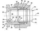
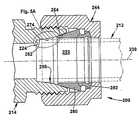
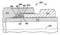
도 1 및 도 2에는 본 명세서에서 설명한 본 발명의 몇몇 양태에 관한 예시적인 실시예인 튜브 이음쇠(10)가 도시되어 있다. 튜브 이음쇠(10)는 튜브(12)와 연결하기 위해 사용되고, 이음쇠 본체(14)를 포함한다. 이음쇠 본체(14)는 단지 본 발명과 함께 사용 가능한 다양한 다른 타입의 조립체와 이음쇠를 나타내는 것이다. 예컨대, 이음쇠 본체는 독립형 장치, 또는 밸브의 일부분, 또는 접합관, 또는 임의의 다른 타입의 유체 제어 장치나 유체 흐름 장치일 수 있다.1 and 2 show a tube fitting 10, which is an exemplary embodiment of some aspects of the invention described herein. The tube fitting 10 is used to connect with the
도시되어 있는 특정 이음쇠 본체(14)는 주본체부(16)와 돌출 소켓벽(20)을 갖는다. 돌출 소켓벽(20)은 이음쇠 본체(14)에 있는 튜브 단부 소켓(22)의 반경 방향 외주부를 형성한다.The particular
이음쇠 본체(14)는 소켓(22)의 축방향 내측 단부(26)에 형성되거나 이 내측 단부에 배치되는 반경 방향 연장 견부(24)를 갖는다. 소켓벽(20)은 이음쇠 본체(14)의 축(30)에 대해 거의 반경 방향으로 연장되는 외측 말단면(28)을 갖는다. 말단면(28)은 소켓(22)의 축방향 외측 단부(32)에 형성되거나 배치된다.The
소켓벽(20)의 외면에 수나사부(40)가 형성된다. 수나사부(40)는 구동 너트(44) 상의 암나사부(42)와 협동한다. 구동 너트(44)는 이음쇠 본체(14)에 대해 회전 가능하고 축방향으로 이동 가능하다.A
소켓벽(20)은 부분적으로 튜브 단부 소켓(22)을 형성하는 내벽면(50)을 갖는다. 내벽면(50)은 튜브 단부 소켓(22)의 축방향 내측 단부(26)와 튜브 단부 소켓의 축방향 외측 단부(32) 사이에서 연장된다. 도시한 실시예에서, 내벽면(50)은 견부(24)와 말단면(28) 사이에서 연장된다. 내벽면(50)은 본 명세서에서 설명하는 본 발명의 양태에 따라 다양한 구성을 가질 수 있다. 본 명세서에서는 복수의 실시예를 예시하지만, 당업자에게는 다른 실시예도 수월하게 명백할 것이다.The
도 1 및 도 2에 도시한 실시예에서, 튜브 단부 소켓(22)의 내벽면(50)은 튜브 포획면(52), 캐밍 마우스부(54), 및 이들 튜브 포획면(52)과 캐밍 마우스부(54) 사이의 중간 벽면부(60)(명확성을 기하기 위해, 도면에서는 세부 사항을 과장하였음)를 포함한다. 예시적인 튜브 포획면(52)은 견부(24)에서부터 축방향 외측으로 연장되지만, 다른 실시예에서 튜브 포획면(52)은 견부(24)로부터 축방향으로 이격 될 수도 있다. 튜브 포획부는 많은 상이한 형상, 각도, 외형 또는 기하학적 형상을 취할 수 있지만, 내벽면(50)의 예시적인 튜브 포획면(52)은 견부(24) 반대측으로 축방향으로 연장됨에 따라 반경 방향 외측으로 테이퍼진 절두 원추형의 테이퍼진 면이다. 도시한 실시예에서는 도 1a에 나타낸 바와 같이, 튜브 포획면(52)이 테이퍼 각도(53)를 갖는다. 예시적인 실시예에서, 테이퍼 각도(53)는 축(30)에 대해 대략 4°이다. 튜브 포획면(52)의 테이퍼 각도(53)와, 그 전체 직경은 이음쇠(10)의 풀업 동안에 튜브(12)가 소켓(22) 내에서 회전하는 것을 방지하기 위해, 이음쇠의 풀업 이전에 튜브(12)의 단부를 가볍게 유지하거나 포획하도록 선택될 수 있다.In the embodiment shown in FIGS. 1 and 2, the
예시적인 캐밍 마우스(54)는 튜브 이음쇠(10)의 부분을 형성하는 페룰(이하에서 설명함)과 맞물리고, 페룰을 반경 방향 내측으로 캐밍시키며, 이에 의해 공지의 방식으로 튜브(12), 페룰 및 이음쇠 본체(14) 간의 파지 및 시일 연결을 제공하도록 되어 있다. 도 1에 나타낸 바와 같은 캐밍 마우스(54)의 각도(57)는 소망하는 파지 및 시일 연결을 제공하도록 선택될 수 있다. 예시적인 실시예에서, 캐밍 마우스의 각도(57)는 축(30)에 대해 대략 20°이다.
도시한 튜브(12)는 단지 본 발명과 함께 사용 가능한 다양한 상이한 타입 및 크기의 도관을 대표하는 것이다. 도시한 특정 튜브(12)는 축(30) 상에 중심이 맞춰진 평행한 원통형 내측면(70) 및 외측면(72)을 포함하는 거의 원통형 구성을 갖는다. 튜브(12)는 내측 튜브 단부(74)와76에서 파단 도시된 외측부를 구비한다. 튜브 이음쇠(10)가 조립될 때, 튜브(12)의 말단부(74)는 이음쇠 본체(14)의 소 켓(22) 내에 배치되고, 튜브는 소켓에서부터 축방향 외측으로, 이음쇠 본체(14) 외부를 향하여 연장된다.The illustrated
도 1 및 도 2에 도시한 특정 튜브 이음쇠(10)는 이음쇠 본체(14) 뿐만 아니라, 전방 페룰(80), 후방 페룰(82) 및 구동 너트(44)를 포함한다. 본 발명은, 예컨대 2개의 페룰보다는 단지 하나의 페룰을 포함하는 튜브 이음쇠와 같은 다른 타입의 튜브 파지 장치를 포함하는 이음쇠에도 적용 가능하다. 본 발명은 상이한 구성들- 이 구성들 중 많은 구성의 디자인이 당업계에 공지되어 있음 -로 이루어진 전방 페룰 및/또는 후방 페룰과 구동 너트를 포함하는 튜브 이음쇠에도 적용 가능하다.The particular tube fitting 10 shown in FIGS. 1 and 2 includes a
도 1에는 풀업 이전에 핑거 타이트 상태의 이음쇠(10)가 도시되어 있다. 튜브(12)는 소켓(22) 내로 삽입된다. 튜브(12)의 말단부(74)는 이음쇠 본체(14)에 있는 내벽면(50)의 튜브 포획면(52)과 접촉하게 연장된다.1 shows the fitting 10 in a finger tight state prior to pull up. The
튜브(12)의 외측면(72)의 직경은 이음쇠 본체(14)의 중간 벽면(60)의 직경보다 작고, 이에 따라 중간 벽면(60)으로부터 반경 방향 내측으로 이격되어 있다. 페룰(80, 82)은 튜브(12) 상에 있으며, 구동 너트(44)는 이음쇠 본체(14)와 나사식으로 맞물린다.The diameter of the
도 2에는 풀업 이후의 이음쇠(10)가 도시되어 있다. 구동 너트(44)는 이음쇠 본체(14) 상으로 더욱 나사 결합되어 있다. 구동 너트(44)의 이동으로 인해, 페룰(80, 82)이 튜브(12)와 이음쇠 본체(14) 간의 파지 및 시일 맞물림을 제공하게 된다.2 shows the fitting 10 after the pull up. The
전방 페룰(80)의 노우즈의 축방향 및 반경 방향 내측 이동으로 인해 튜브(12)가 축방향 내측으로 압박되어 견부(24)와 맞물리게 된다. 튜브(12) 상의 축방향 힘으로 인해, 전방 페룰(80)의 축방향 내측에 배치된 튜브 단부(74) 부분이 반경 방향 외측으로 불룩해진다. 이러한 튜브 부분(74)은, 예컨대 도 2에 도시한 바와 같이 이음쇠 본체(14)의 중간 벽면부(60)와 접촉할 수 있어, 간섭 하중 또는 마찰 하중으로도 칭할 수 있는, 반력의 반경 방향 성분을 생성한다.The axial and radially inward movement of the nose of the
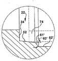
예시적인 내벽면(50)의 중간 벽면부(60)는 튜브 포획면(52)과 캐밍 마우스부(54) 사이에서 연장된다. 중간 벽면부(60)는 축(30) 상에 중심이 맞춰진다. 예시적인 중간 벽면부(60)는 튜브 포획면(52)의 축방향 외측에 있는 단차부(61)(도 1a 참고)와, 이 단차부(61)의 축방향 외측에 있는 오목부(62)를 포함하기 때문에, 이 오목부(62)가 튜브 포획면(52)으로부터 반경 방향으로 이격되어 있다. 이에 따라, 소켓(22)의 직경은 포획면(52)을 따른 임의의 지점에서보다 오목부(62)에서 크다. 더욱이, 소켓(22)의 내벽면(50)의 평균 직경은 그러한 오목부가 없는 이음쇠의 튜브 소켓에 비해 증가된다. 또한, 도시한 단차부(61)는 튜브 포획면(52)에 직접 인접하지만, 다른 실시예에서 단차부(61)는 튜브 포획면(52)의 외측 에지로부터 축방향으로 이격될 수 있다.The
도 1, 도 1a, 도 2 및 도 2a에 도시한 실시예에서, 예시적인 단차부(61)는 거의 원통형인 예시적인 오목부(62)와 거의 수직이다. 그 결과, 도 2a에 도시한 바와 같이 튜브 단부(74)가 이음쇠의 풀업 중에 확대되어 오목부(62)와 접촉할 때, 원통형 오목부(62)와 튜브 단부(74) 간의 반력은 거의 반경 방향(즉, 비축방향)의 것이다. 또한, 확대된 튜브 단부(74)와 예시적인 단차부(61)의 접촉은 최소이기 때문에, 그러한 접촉으로 인한 축방향 반력은 거의 없거나 전혀 없게 된다. 예시적인 이음쇠(10)의 해체중에, 테이퍼진 튜브 포획면(52)과 튜브 단부(74) 간의 맞물림은 이음쇠 본체로부터 튜브 단부를 분리하는 데 기여하는 축방향 반력을 제공할 것이다. 분리중에, 보다 적은 확대 또는 변위를 겪은 튜브 단부(74)가 튜브 소켓의 오목부(62) 내로 축방향으로 이동하기 때문에, 오목부(62)와 튜브(12) 사이의 반경 방향 반력은 감소되거나 제거되고, 이에 따라 이음쇠 본체(14)로부터 튜브 단부(74)를 분리하는 데 기여한다. 더욱이, 튜브 소켓(22)에 있는 내벽면(50)의 평균 직경을 증가시킴으로써, 튜브(12)와 튜브 소켓(22)의 접촉 길이를 따른 총 반경 방향 반력이 감소된다.In the embodiment shown in FIGS. 1, 1A, 2 and 2A, the
다른 실시예에서는 도 1b 및 도 2b의 부분도에 도시한 바와 같이, 단차부(61')가 테이퍼져, 이음쇠의 풀업시에 도 2b에 도시한 바와 같이 튜브와 단차부(61')의 접촉이 증가할 가능성을 허용할 수 있다. 튜브(12)와 테이퍼진 단차부(61') 간의 가능한 접촉은 이음쇠의 해체중에, 이음쇠 본체(14)로부터 튜브(12)를 분리하는 데 기여하는, 튜브와 단차부(61') 간의 반력의 축방향 성분을 제공한다. 단차부(61')는 많은 상이한 각도로, 그리고 많은 상이한 표면 외형을 갖게 마련될 수 있지만, 예시적인 실시예는 축(30)에 대한 테이퍼 각도(63')가 대략 20°인 절두 원추형 단차부(61')를 포함한다.In another embodiment, as shown in the partial views of FIGS. 1B and 2B, the stepped portion 61 'is tapered so that the tube and the stepped portion 61' contact as shown in FIG. 2B when the fitting is pulled up. This could allow the possibility of increasing. The possible contact between the
다른 실시예에서, 단차부(61')는 보다 가팔라, 즉 보다 큰 테이퍼 각도(63')를 지녀, 축방향으로 보다 짧은 단차부(61')와 보다 긴 오목부(62')가 형성될 수도 있고, 단차부(61')는 보다 얕아, 즉 보다 작은 테이퍼 각도(63')를 지녀, 축방향으로 보다 긴 단차부(61')와 보다 짧은 오목부(62')가 형성될 수도 있다. 튜브 상에 축방향 탄성 반력을 제공할 수 있는 시스템을 얻기 위해서, 특정 이음쇠에 관한 유한 요소 해석과 시험이, 해체시에 튜브 분리에 기여하기 위해 얼마나 큰 테이퍼가 필요한지를 결정할 수 있다.In another embodiment, the stepped portion 61 'has a steeper, i.e., a greater taper angle 63', formed with a shorter stepped portion 61 'and a longer recess 62' in the axial direction. The stepped portion 61 'may be shallower, i.e. have a smaller taper angle 63', so that a longer stepped portion 61 'and a shorter recess 62'in the axial direction may be formed. have. In order to obtain a system capable of providing axial elastic reaction forces on the tube, finite element analysis and testing on a particular fitting can determine how large a taper is needed to contribute to tube separation at disassembly.
다양한 예시적인 실시예에서, 이음쇠 본체의 단차형 또는 테이퍼진 중간 벽부는 튜브 소켓의 튜브 포획부와 캐밍 마우스부와 불연속적일 수 있는데, 즉 단차형 또는 테이퍼진 중간 벽부는 튜브 포획부(152) 및 캐밍 마우스부(154)와 상이한 각도로 마련될 수 있고, 튜브 포획부(152) 및 캐밍 마우스부(154)로부터 반경 방향으로 이격되어 있을 수 있으며, 및/또는 튜브 포획부(152)와 캐밍 마우스부(154)로부터 축방향으로 이격되어 있을 수 있다.In various exemplary embodiments, the stepped or tapered intermediate wall portion of the fitting body may be discontinuous with the tube catch and camming mouth portion of the tube socket, ie the stepped or tapered intermediate wall portion may be
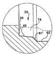
일실시예에서는 도 3 및 도 4에 도시한 바와 같이, 이음쇠 본체(114)에 캐밍 마우스부(154)의 내측 에지까지 연장되는 테이퍼진 길이 방향 면을 지닌 단차부(160)를 포함하는 튜브 소켓이 마련되고, 이에 따라 튜브 소켓(122)의 별도의 오목부를 배제할 수 있다. 이음쇠의 풀업후에 단차부 또는 테이퍼진 내벽(160)과 확대된 튜브 단부(174) 간의 맞물림 또는 접촉은, 그러한 접촉이 일어날 때 튜브(112)와 테이퍼진 내벽(160) 간의 접촉 길이를 따른 반력의 축방향 성분을 생성하고, 이에 따라 이음쇠 본체(114)로부터 튜브 단부를 분리하는 데 기여한다. 또한, 도시한 단차부 또는 테이퍼진 벽부(160)는 튜브 포획부(152)에 직접 인접하지만, 단차부는 튜브 포획부(152)의 외측 에지로부터 축방향으로 이격될 수도 있다.In one embodiment, as shown in FIGS. 3 and 4, a tube socket including a stepped
(원통면과 대립되는) 벽면(160)의 테이퍼진 상태는 해체시에 소켓(122)으로부터 튜브(112)를 분리하는 데 기여할 수 있다. 튜브 단부(174)가 초기에 테이퍼진 벽면(160)에서 빠져나오고 나면, 튜브(112)는 튜브 단부(174)와 테이퍼진 벽면(160) 간의 반경 방향 반력의 감소 또는 제거로 인해 어떠한 실질적인 힘 없이도 분리될 수 있다.The tapered state of the wall surface 160 (as opposed to the cylindrical surface) may contribute to separating the
테이퍼진 벽면은 다양한 테이퍼 각도로, 그리고 다양한 표면 외형을 갖게 마련될 수 있다. 일실시예에서, 테이퍼진 벽면은 절두 원추형으로 테이퍼져 튜브 포획부의 외측 에지와 캐밍 마우스부의 내측 에지를 연결한다. 도 3 및 도 4에 도시한 실시예에서, 테이퍼진 벽면(160)은 소정 테이퍼 각도(163)를 갖는 절두 원추형이다. 일실시예에서, 테이퍼 각도(163)는 축(130)에 대해 대략 50', 즉 1°의 5/6이다. 그러한 실시예에서, 예시적인 테이퍼진 벽면(160)의 테이퍼 각도(163)는 튜브 포획부(152)의 테이퍼 각도(153)보다 훨씬 작다. 이하에서 설명하겠지만, 테이퍼진 벽면(160)의 테이퍼 각도(163)는, 튜브 단부가 이음쇠의 풀업중에 반경 방향 외측으로 확대되어 소켓벽과 접촉하는 경우에 튜브 단부의 분리에 기여하도록 선택된다. 한가지 바람직한 테이퍼 각도 범위는 50' 내지 1°50'으로, 공차가 ± 15'이다.Tapered wall surfaces may be provided at various taper angles and with various surface appearances. In one embodiment, the tapered wall is tapered conically to connect the outer edge of the tube catch and the inner edge of the camming mouth. In the embodiment shown in FIGS. 3 and 4, the tapered
본 출원의 발명의 다른 양태에 따르면, 이음쇠 본체로부터의 튜브 단부의 분리는 추가적으로 또는 대안으로서 이음쇠의 풀업시에 튜브 소켓과 접촉하는 튜브 부분의 길이를 감소시키는 것에 의해 용이해질 수 있다. 이것은 이러한 접촉면들 간의 총 반경 방향 반력을 감소시키고, 이에 따라 해체시에 이음쇠 본체로부터 튜 브 단부를 분리하는 데 기여할 수 있다. 일실시예에서, 확대된 튜브 단부와 튜브 단부 소켓 간의 접촉 길이는 도 1 내지 도 4의 실시예에 관하여 전술한 바와 같이 튜브 단부 소켓 내에 오목면 또는 테이퍼진 길이 방향 면을 제공하는 것에 의해 감소될 수 있다. 다른 실시예에서, 확대된 튜브 단부와 튜브 단부 소켓 간의 접촉 길이는 추가적으로 또는 대안으로서 튜브 소켓의 길이를 감소시키는 것에 의해 감소될 수 있다. 도 5 및 도 6에는 그러한 예시적인 일실시예인 이음쇠(200)가 도시되어 있다. 이음쇠(200)에서, 이음쇠 본체(214)는 얕은 또는 단축된 소켓(222)을 구비한다. 소켓(222)의 외주부는 이음쇠 본체(214)의 내벽면(250)에 의해 형성된다. 내벽면(250)은 튜브 포획부(252)와 캐밍 마우스(254)를 포함하며, 이들의 각도는 명확성을 기하기 위해 도면에서 과장될 수 있다.According to another aspect of the invention of the present application, detachment of the tube end from the fitting body can additionally or alternatively be facilitated by reducing the length of the tube portion in contact with the tube socket upon pull up of the fitting. This reduces the total radial reaction force between these contact surfaces, thus contributing to separating the tube end from the fitting body upon disassembly. In one embodiment, the contact length between the enlarged tube end and the tube end socket is reduced by providing a concave or tapered longitudinal face in the tube end socket as described above with respect to the embodiment of FIGS. Can be. In another embodiment, the contact length between the enlarged tube end and the tube end socket may be reduced by additionally or alternatively reducing the length of the tube socket. 5 and 6 illustrate one such exemplary embodiment, fitting 200. In fitting 200,
도 5 및 도 6의 예시적인 내벽면(250)은 도 1 내지 도 4의 실시예의 중간 벽면(60, 160)과 같은 중간 벽면을 포함하지 않는다. 그보다는, 튜브 포획부(252)가 캐밍 마우스(254)에 접한다. 즉, 캐밍 마우스(254)는 중간 길이부 또는 천이 길이부가 없는 튜브 소켓(222)을 제공하도록 튜브 포획면(252)에 직접 인접한다. 따라서, 예시적인 이음쇠 본체(214)의 튜브 포획부(252)와 캐밍 마우스(254) 사이에는, 테이퍼진 벽면, 단차형 벽면, 원통형 벽면 중 그 어느 것도 존재하지 않는다. 튜브 포획부(252)와 캐밍 마우스(254)의 테이퍼 각도(253, 257)는 시험 및 유한 요소 해석에 의해 결정된 바와 같은 임의의 개수의 상이한 각도일 수 있지만, 예시적인 실시예에서 튜브 포획부(252)는 테이퍼 각도(253)가 대략 4°이고, 캐밍 마우스는 테이퍼 각도가 대략 20°이다.The exemplary
다른 실시예에서, 튜브 소켓의 길이는 이음쇠의 풀업시 그리고 후속하는 이음쇠의 해체 모두에서 튜브 소켓과 튜브 단부 간의 소망하는 반경 방향 힘을 제공하도록 선택될 수 있다. 얕은 튜브 소켓에는, 대안으로서 튜브 포획면과 캐밍 마우스 사이에 원통형 중간 튜브벽 또는 단차형 중간 튜브벽이 마련될 수 있다. 적절한 소켓의 길이 및/또는 중간 튜브벽의 기하학적 형상은 유한 요소 해석 및 시험에 의해 결정될 수 있다.In another embodiment, the length of the tube socket can be selected to provide the desired radial force between the tube socket and the tube end both in pull up of the fitting and in subsequent disassembly of the fitting. The shallow tube socket may alternatively be provided with a cylindrical intermediate tube wall or a stepped intermediate tube wall between the tube trapping surface and the caming mouse. The length of the appropriate socket and / or the geometry of the intermediate tube wall can be determined by finite element analysis and testing.
본 발명의 다른 양태에 따르면, 하나 이상의 테이퍼진 길이 방향 면이 하나 이상의 다른 이음쇠 조립체 구성 요소 상에 마련될 수 있다. 일실시예에서, 테이퍼진 길이 방향 면은 이음쇠 조립체의 구동 너트의 내벽 상에 마련되어, 튜브 파지 장치의 일부분이 풀업중에 외측 방향으로 변위되어 구동 너트의 내벽과 접촉할 때 이음쇠와 조립된 튜브 파지 장치의 일부분과 맞물릴 수 있다. 테이퍼진 길이 방향 면과 튜브 파지 요소 간의 이러한 접촉은 이음쇠 해체시에 튜브 파지 장치로부터 구동 너트를 분리하는 데 기여할 수 있는, 튜브 파지 장치에 대한 탄성 반력의 축방향 성분을 생성한다. 도 7 내지 도 12에는 그러한 테이퍼진 길이 방향 면 중 하나 이상을 갖는 구동 너트를 포함하는 이음쇠의 예시적인 실시예가 도시되어 있다.According to another aspect of the invention, one or more tapered longitudinal faces may be provided on one or more other fitting assembly components. In one embodiment, the tapered longitudinal face is provided on the inner wall of the drive nut of the fitting assembly such that a portion of the tube gripping device is assembled with the fitting when the portion of the tube gripping device is displaced outward during contact with the inner wall of the drive nut. Can be engaged with part of the. This contact between the tapered longitudinal face and the tube gripping element creates an axial component of elastic reaction force against the tube gripping device that may contribute to separating the drive nut from the tube gripping device upon fitting disassembly. 7-12 an exemplary embodiment of a fitting including a drive nut having one or more of such tapered longitudinal faces is shown.
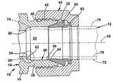
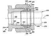
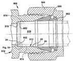
일실시예에 따르면, 도 7 및 도 8에는 2개 페룰 튜브 이음쇠(300)가 도시되어 있다. 튜브 이음쇠(300)는 튜브(312)와의 연결을 위해 사용될 수 있으며, 이음쇠 본체(314)를 포함한다. 이음쇠 본체(314)는 단지 본 발명과 함께 사용 가능한 다양한 상이한 타입의 조립체 및 이음쇠를 대표하는 것이다. 예컨대, 이음쇠 본체는 독립형 장치, 또는 밸브의 일부분, 또는 접합관, 또는 임의의 다른 타입의 유체 제어 장치 또는 유체 흐름 장치일 수 있다. 더욱이, 이음쇠 본체(314)에는, 필수적인 것은 아니지만, 예컨대 도 1 내지 도 6에 도시하고 전술한 테이퍼진 튜브 포획부 및 튜브 단부 소켓 벽면과 같이 오목면 또는 테이퍼진 길이 방향 면이 마련될 수 있다. 도 7 및 도 8에 도시한 특정 튜브 이음쇠(300)는 이음쇠 본체(314) 뿐만 아니라, 전방 페룰(380), 후방 페룰(382) 및 구동 너트(344)를 포함한다.According to one embodiment, two
도 7 및 도 7a에는 풀업 이전에 핑거 타이트 상태의 이음쇠(300)가 도시되어 있다. 튜브(312)는 구동 너트(344)를 통해 소켓(322) 내로 삽입된다. 전방 페룰(380)은 구동 너트(344)에 있는 오목부(345)의 제1 부분에 배치되고, 후방 페룰(382)은 오목부(345)의 제2 부분에 배치된다. 오목부에는 풀업중에 페룰(380, 382)을 튜브와 맞물리게 구동하기 위한 절두 원추형 구동면(349)이 포함된다.7 and 7a show fitting 300 in a finger tight state prior to pull up. The
도 8에는 풀업 이후의 이음쇠(300)가 도시되어 있다. 구동 너트(344)는 이음쇠 본체(314) 상에 더욱 나사 결합된다. 구동 너트(344)의 이동으로 인해 페룰(380, 382)이 튜브(312)와 이음쇠 본체(314) 간의 파지 및 시일 맞물림을 제공한다.8 shows the fitting 300 after pull up. Drive
전방 페룰(380)의 노우즈의 축방향 및 반경 방향 내측 이동으로 인해 전방 페룰(380)의 외측부(380r)가 외측 방향으로 확대되거나 편향되게 될 수 있다. 이와 마찬가지로, 후방 페룰(382)의 내측 파지부의 축방향 및 반경 방향 내측 이동으로 인해, 후방 페룰(382)의 외측부(382r)가 외측 방향으로 확대되거나 편향되게 될 수 있다. 어떠한 상황 하에서, 페룰(380, 382)의 이들 외측부 중 어느 하나 또는 양자가 풀업중에 구동 너트(344)의 내벽(346)과 접촉할 수 있다. 도 7 및 도 8의 예시적인 실시예에서, 테이퍼진 길이 방향 면(347, 348)이 내벽(346) 상에서 전방 페룰(380) 및 후방 페룰(382)과 축방향으로 정렬된 부위에 마련된다. 다른 실시예에서는 테이퍼진 길이 방향 면이 2개의 페룰 중 단지 하나와 축방향으로 정렬되게 마련될 수도 있고, 내벽 상의 하나의 연속적인 테이퍼진 길이 방향 면이 2개의 페룰과 축방향으로 정렬되게 연장될 수도 있다는 점에 주목해야 한다(도시하지 않음). 도 7 및 도 8에 도시한 실시예에서, 전방 페룰(380)과 후방 페룰(382)의 외측부(380r, 382r)가 풀업중에 편향될 때, 도 8에 도시한 바와 같이 외측부(380r, 382r) 중 어느 하나 또는 이들 양자는 테이퍼진 길이 방향 면 중 대응하는 어느 하나 또는 이들 양자와 접촉하여, 반력의 반경 방향 성분 및 축방향 성분 모두를 생성할 수 있다.The axial and radial inward movement of the nose of the
이들 내벽면(347, 348)의 테이퍼진 상태는 해체시에 하나의 페룰 또는 2개의 페룰(380, 382)로부터 구동 너트(344)를 분리하는 데 기여할 수 있다. 테이퍼진 면(347, 348)과 페룰(들)(380, 382)의 접촉에 의해 생성되는 반력의 축방향 성분은 페룰(380, 382) 중 어느 하나 또는 이들 양자로부터 구동 너트(344)를 분리하는 데 기여할 수 있다. 페룰(들)(380, 382)이 초기에 테이퍼진 벽면(347, 348)으로부터 빠져나오고 나면, 구동 너트(344)는 페룰(들)(380, 382)과 테이퍼진 벽면(347, 348) 간의 반경 방향 반력에 있어서의 감소 또는 결과적인 반경 방향 분리로 인해 어떠한 실질적인 힘 없이도 분리될 수 있다.The tapered state of these inner wall surfaces 347, 348 may contribute to separating the
페룰의 충분한 반경 방향 구속과, 해체중에 접촉하는 구동 너트와 페룰면들 간의 충분한 축방향 반력을 제공하기 위해서, 구동 너트(344)에 있는 내벽면(347, 348)의 테이퍼 각도(341, 343)는 각각 구동 너트의 축(330)에서 측정하였을 때, 예컨대 0°보다 크고 대략 최대 45°의 범위일 수 있다. 이들 2개의 각도(341, 343)는 동일할 수 있지만, 이것이 필수적인 것은 아니다. 예시적인 실시예에서, 테이퍼 각도(341, 343)는 각각 약 5°에서 최대 약 30°의 범위일 수 있으며, 보다 바람직한 실시예에서 테이퍼 각도(341, 343)는 각각 약 10°내지 약 20°의 범위일 수 있지만, 이것이 필수적인 것은 아니다. 도 7 및 도 8에 도시한 실시예에서, 테이퍼진 벽면(347, 348)은 각각 축(330)에 대해 약 10°인 테이퍼 각도(341, 343)를 갖는다.Taper angles 341 and 343 of the inner wall surfaces 347 and 348 in the
전술한 바와 같이, 구동 너트에 있는 테이퍼진 벽면의 테이퍼 각도는 튜브 파지 장치의 임의의 부분이 풀업중에 반경 방향 외측으로 확대되거나 편향되어 구동 너트의 내벽과 맞물리는 경우, 예컨대 페룰(들)과 같은 튜브 파지 장치로부터 구동 너트를 분리하는 데 기여하도록 선택될 수 있다. 추가적으로, 이음쇠가 미리 조여진, 즉 핑거 타이트 상태일 때, 튜브 파지 장치의 외측부(들)와 구동 너트의 테이퍼진 길이 방향 면(들) 간의 간극은 독립적으로 또는 테이퍼 각도와 함께 페룰(들)의 외측부들과 구동 너트의 내벽 사이에, 튜브 단부에 튜브 파지 장치를 조이는 데 기여하는 소망하는 반경 방향 반응 하중을 제공하도록 선택될 수 있다. 예시적인 실시예에서는 도 7 및 도 7a에 도시한 바와 같이, 전방 페룰의 외측부(380r)와 테이퍼진 길이 방향 면(347) 사이에 간극(g1)이 마련되고, 후방 페룰의 외측부(382r)와 테이퍼진 길이 방향 면(348) 사이에 간극(g2)이 마련된다. 이들 간극의 치수와 테이퍼진 길이 방향 면의 테이퍼 각도는, 예컨대 도 1 내지 도 6에 도시한 구동 너트(44, 144, 244)와 같은 원통형 내벽면을 지닌 너트와 함께 이음쇠(300)를 풀업하는 동안에 겪는 것과 일치하는 반경 방향 반력을 생성하는 것과 같이 이음쇠를 풀업하는 동안에 소망하는 반경 방향 반력을 생성하도록 변할 수 있다. 이와 같이, 테이퍼진 길이 방향 면을 지닌 구동 너트(344)는 원통형 내벽면을 지닌 너트와 호환 가능하고, 이에 따라 동일한 이음쇠 본체와 튜브 파지 장치의 사용을 허용할 수 있다. 그러한 예시적인 일실시예에서, 1/2 인치 관을 위한 튜브 이음쇠(300)는 전방 페룰(380)과 테이퍼진 길이 방향 면(347) 사이에 대략 0.010 인치의 간극(g1)을 포함하고, 후방 페룰(382)과 테이퍼진 길이 방향 면(348) 사이에 대략 0.009 인치의 간극(g2)을 포함한다.As noted above, the taper angle of the tapered wall on the drive nut is such that, for example, when any portion of the tube gripping device is radially outwardly or deflected during pull up to engage the inner wall of the drive nut, such as for example ferrule (s). It may be selected to contribute to separating the drive nut from the tube gripping device. Additionally, when the fitting is pre-tightened, i.e. in a finger tight state, the gap between the outer portion (s) of the tube gripping device and the tapered longitudinal face (s) of the drive nut is independently or with the taper angle the outer portion of the ferrule (s). It can be chosen between the fields and the inner wall of the drive nut to provide the desired radial reaction load which contributes to tightening the tube gripping device at the tube end. In the exemplary embodiment, as shown in FIGS. 7 and 7A, a gap g1 is provided between the
본 발명의 다른 양태에 따르면, 테이퍼진 길이 방향 면이 이음쇠의 복수의 구성 요소 상에 마련되어 이음쇠의 조립중에 접촉하는 복수 세트의 이음쇠의 구성 요소를 분리하는 데 기여할 수 있다. 일실시예에서, 테이퍼진 길이 방향 면은 이음쇠의 해체중에 튜브 단부와 튜브 파지 장치 각각으로부터의 분리를 위해 본체 튜브 소켓의 내벽 상과 구동 너트의 내벽 상 모두에 마련된다. 도 7 및 도 8에 도시한 예시적인 실시예에는, 전술한 바와 같은 구동 너트(344) 상의 테이퍼진 길이 방향 면(347, 348) 뿐만 아니라, 테이퍼진 중간 소켓 벽면(360)이 튜브 포획부(352)와 캐밍 마우스(354) 사이에 마련되는데, 상기 테이퍼진 중간 소켓 벽면은 풀업된 이음쇠(300)의 해체 동안에 튜브(312)로부터 이음쇠 본체(314)를 분리하는 데 기여하는 도 3 및 도 4의 테이퍼진 내벽면(160)과 일치한다.According to another aspect of the present invention, a tapered longitudinal face may be provided on a plurality of components of the fitting to contribute to separating the components of the plurality of sets of fittings that contact during the assembly of the fitting. In one embodiment, the tapered longitudinal face is provided both on the inner wall of the body tube socket and on the inner wall of the drive nut for removal from each of the tube end and the tube gripping device during disassembly of the fitting. In the exemplary embodiment shown in FIGS. 7 and 8, tapered intermediate socket wall surfaces 360, as well as tapered
도 9 및 도 10에는 테이퍼진 길이 방향 면(447)이 구동 너트(444)의 내벽 상 에 마련되는 다른 예시적인 실시예인 이음쇠(400)가 도시되어 있다. 도 9 및 도 10의 예시적인 이음쇠는, 공개 번호 제US 2006/0049632호로 공개되어 있고, 발명의 명칭이 스테인리스 강관용 튜브 이음쇠인, 공동 계류중인 출원 번호 제10/467,241호- 전체 내용이 참고에 의해 본 명세서에 완전히 통합됨 -에 설명되는 있는 단일 페룰 튜브 이음쇠와 유사한 단일 페룰 구성이다.9 and 10 show another exemplary embodiment of a fitting 400 where a tapered
도시한 튜브 이음쇠의 풀업중에, 전방 페룰(480)의 노우즈의 축방향 및 반경 방향 내측 이동으로 인해 전방 페룰(480)의 외측부(480r)가 외측 방향으로 확대되거나 편향되게 될 수 있다. 어떠한 환경 하에서, 이러한 페룰(480)의 외측부(480r)는 풀업중에 구동 너트(444)의 내벽(446)과 접촉하여, 페룰(480)의 외측부(480r)와 구동 너트(444)의 내벽(446) 간의 반경 방향 반응 하중을 유발할 수 있다. 도 9 및 도 10의 예시적인 실시예에서, 테이퍼진 길이 방향 면(447)은 내벽(446) 상에서 페룰(480)과 축방향으로 정렬되고 반경 방향으로 이격되어 있는 부위에 마련된다. 풀업중에 페룰(480)의 외측부(480r)가 편향될 때, 도 9에 도시한 바와 같이 외측부(480r)는 테이퍼진 길이 방향 면(447)과 접촉하여, 반력의 반경 방향 성분과 축방향 성분 모두가 생성될 수 있다. (예컨대 원통면과 대립되는) 내벽면의 테이퍼진 상태는, 반력의 축방향 성분이 페룰(480)로부터 구동 너트(444)를 분리하는 데 기여할 수 있기 때문에, 해체시에 페룰(480)로부터 구동 너트(444)를 분리하는 데 기여할 수 있다. 페룰(480)이 초기에 테이퍼진 벽면(447)으로부터 빠져나오고 나면, 구동 너트(444)는 테이퍼진 길이 방향 면(447)의 테이퍼 각도로 인해 어떠한 실질적인 힘 없이도 분리될 수 있다.During pull-up of the illustrated tube fittings, the axial and radial inward movement of the nose of the
도 11 및 도 12에는 테이퍼진 길이 방향 면(548)이 구동 너트(544)의 내벽 상에 마련되는 또 다른 예시적인 실시예인 이음쇠(500)가 도시되어 있다. 도 11 및 도 12의 예시적인 이음쇠는 공개 번호 제US 2005/0242582호로 공개되고, 발명의 명칭이 튜브 및 파이프용 이음쇠인, 공동 계류중인 출원 번호 제11/112,800호- 전체 내용이 참고에 의해 본 명세서에 완전히 통합됨 -에 설명되는 있는 수나사형 구동 너트를 구비하는 튜브 이음쇠와 유사한, 수나사형 구동 너트(544)와 암나사형 이음쇠 본체(514)를 이용하는 타입의 2개 페룰 이음쇠이다.11 and 12 show another exemplary embodiment of a fitting 500 in which a tapered longitudinal surface 548 is provided on the inner wall of the
도시한 튜브 이음쇠의 풀업중에, 전방 페룰(580)의 노우즈의 축방향 및 반경 방향 내측 이동으로 인해 전방 페룰(580)의 외측부(580r)가 외측 방향으로 확대되거나 편향되게 될 수 있다. 이와 마찬가지로, 후방 페룰(582)의 내부 파지부의 축방향 및 반경 방향 내측 이동으로 인해 후방 페룰의 외측부(582r)가 외측 방향으로 확대되거나 편향되게 될 수 있다. 어떠한 환경 하에서, 페룰(580, 582)의 이들 외측부(580r, 582r) 중 어느 하나 또는 모두는 풀업중에 구동 너트(544)의 내벽(546)에 접촉하여, 페룰(들)(580, 582)의 외측부(580r, 582r)와 구동 너트(544)의 내벽(546) 사이에 반경 방향 반응 하중을 유발할 수 있다. 도 11 및 도 12의 예시적인 실시예에서, 테이퍼진 길이 방향 면(547)은 내벽(546) 상에서 페룰(580, 582)과 축방향으로 정렬되고 반경 방향으로 이격되어 있는 부위에 마련된다. 페룰(580, 582)의 외측부(580r, 582r)가 풀업중에 편향될 때, 도 12에 도시한 바와 같이 외측부(580r, 582r) 중 어느 하나 또는 모두는 테이퍼진 길이 방향 면(547)과 접촉하여, 접촉하는 면들 간의 반력의 반경 방향 성분 및 축방향 성분 모두를 생성할 수 있다. (예컨대 원통면과 대립되는) 내벽면(547)의 테이퍼진 상태는, 반력의 축방향 성분이 페룰(580, 582)로부터 구동 너트(544)를 분리하는 데 기여할 수 있기 때문에, 해체시에 페룰(580, 582)로부터 구동 너트(544)를 분리하는 데 기여할 수 있다. 페룰(들)(580, 582)이 초기에 테이퍼진 벽면(547)으로부터 빠져나오고 나면, 구동 너트(544)는 테이퍼진 길이 방향 면의 테이퍼 각도로 인해 어떠한 실질적인 힘 없이도 분리될 수 있다.During pull-up of the tube fittings shown, the axial and radial inward movement of the nose of the
본 발명의 또 다른 양태에 따르면, 제1 이음쇠 구성 요소와 제2 이음쇠 구성 요소를 분리하는 데 대한 기여는 제2 이음쇠 구성 요소를 축방향으로 압박하는 동안 제2 이음쇠 구성 요소의 반경 방향 외측 편향을 감소시켜 제1 이음쇠 구성 요소와 제2 이음쇠 구성 요소 간의 반경 방향 반력을 감소시키는 것에 의해 얻어질 수 있다. 예컨대, 굴곡 상쇄 특징부가 이음쇠 본체에 마련되어, 이음쇠 조립중에 튜브 단부의 외측 방향 편향 또는 굴곡을 감소시킬 수 있다. 굴곡 상쇄 특징부를 구비하는 일실시예에서, 튜브 단부를 수용하는 소켓을 구비하는 이음쇠 구성 요소에는 축방향으로 쑥 들어간 견부면 또는 축방향으로 그리고 소켓의 길이 방향 벽면의 축방향 내측 단부로부터 반경 방향 내측으로 연장되는 면을 지닌 견부가 마련될 수 있다.According to another aspect of the invention, the contribution to separating the first fitting component and the second fitting component is such that the radially outward deflection of the second fitting component while axially compressing the second fitting component. By reducing the radial reaction force between the first fitting component and the second fitting component. For example, flexural offset features may be provided in the fitting body to reduce outward deflection or flexion of the tube ends during fitting assembly. In one embodiment with a flex offset feature, a fitting component with a socket for receiving a tube end may have a radially inward shoulder or an axially radially inward end from an axially inner end of the longitudinal wall of the socket. Shoulders with sides extending to the side may be provided.
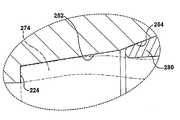
도 13에는 환형 길이 방향 벽면(612)과, 축방향으로 그리고 상기 환형 길이 방향 벽면(612)의 축방향 내측 단부의 반경 방향 내측으로 연장되는 축방향으로 쑥 들어간 견부면(615)을 지닌 소켓(610)을 구비하는 이음쇠 구성 요소(600)가 도시되어 있다. 튜브 단부(674)가 튜브 소켓(610) 내에서 견부면(615)의 외측부(616)에 대하여 축방향으로 압박될 때, 화살표A로 나타낸 외측 방향 굴곡력은 튜브 단부(674)가 외측 방향으로 굴곡되게 하거나 불룩해지게 하여 길이 방향 벽면(612)과 맞물리게 하는 경향이 있다. 견부면(615)을 튜브 단부(674)와 맞물리는 외측부(616)의 내측으로 축방향으로 쑥 들어가게 하는 것에 의해, 튜브 단부(674)의 내측부(676)와 견부(615) 사이의 간극(G)이 굴곡력(A)을 적어도 부분적으로 상쇄시키는 화살표 B로 나타낸 내측 방향 선회력을 부여하고, 이에 따라 굴곡 또는 불룩해짐으로 인한 튜브 단부(674)의 확대를 감소시킨다. 이렇게 감소된 튜브 단부(674)의 반경 방향 확대는 해체중에 이음쇠 구성 요소(600)에서 튜브 단부(674)를 분리하는 것을 용이하게 할 수 있다.13 shows a socket having an annular
많은 상이한 타입의 축방향으로 쑥 들어간 견부면은, 환형 길이 방향 벽면에서부터 (직접 또는 반경 방향으로 이격되어) 연장되는, 예컨대 절두 원추형 면, 요면(凹面), 철면(凸面)이나 단차면, 또는 상이한 외형 또는 기하학적 형상의 조합을 포함하고, 이음쇠 구성 요소에 마련될 수 있다. 도시한 실시예에서, 축방향으로 쑥 들어간 견부면(615)은 이 견부면(615)의 거의 평평한 외측부(616)에서부터 연장되는 절두 원추형면을 포함하며, 상기 외측부는 길이 방향 벽면(612)까지 연장된다. 이러한 평평한 외측부는, 예컨대 튜브 단부(674)가 축방향 압박 이전 또는 축방향 압박 동안에 맞닿는 튜브 단부 맞물림면을 제공할 수 있다.Many different types of axially protruding shoulder surfaces extend from the annular longitudinal wall surface (directly or radially spaced apart), such as truncated conical surfaces, concave surfaces, convex or stepped surfaces, or different It may include a combination of contours or geometries and may be provided in the fitting component. In the illustrated embodiment, the axially recessed
이러한 굴곡 상쇄 특징부는, 소켓에 삽입되는 동안에 축방향 압박을 경험하는 튜브 단부와 같은 다른 이음쇠 구성 요소를 수용하는, 예컨대 이음쇠 조립 이전에 튜브 단부에 페룰(들)과 같은 튜브 파지 부재를 사전 조립 또는 스웨이징하는 이음쇠 설치 공구를 포함하는, 소켓을 구비하는 임의의 이음쇠 구성 요소를 포함하는 많은 상이한 타입의 이음쇠 구성 요소에 마련될 수 있다. 본 발명의 양태를 적용할 수 있는 그러한 이음쇠 설치 공구의 일례는 발명의 명칭이 "페룰 스웨이징용 장치"인 미국 특허 제6,463,778호(이하, "'778 특허"라고 함)- 전체 내용이 참고에 의해 본 명세서에 통합됨 -에 설명되어 있는 유압식 수동 조작 스웨이징 유닛이다.This bend canceling feature pre-assembles or holds a tube gripping member, such as a ferrule (s), at the tube end prior to fitting assembly, for example receiving other fitting components such as the tube end experiencing axial compression while being inserted into the socket. It can be provided in many different types of fitting components, including any fitting component with a socket, including a fitting for swaging fittings. One example of such a fitting installation tool, to which aspects of the present invention can be applied, is U.S. Patent No. 6,463,778 (hereinafter referred to as "'778 patent"), entitled "Device for Ferrule Swaging," the entire contents of which are incorporated by reference. It is a hydraulic manually operated swaging unit as described in Incorporated herein.
도 14에는, 예컨대 '778 특허의 예시적인 유압식 스웨이징 유닛과 같은 스웨이징 공구와 함께 사용하는 예시적인 조임 또는 스웨이징 다이(700)가 도시되어 있다. 스웨이징 다이(700)는 축방향 외측 캐밍면(711), 환형 길이 방향 벽면(712) 및 축방향으로 쑥 들어간 견부면(715)을 지닌 소켓(710)을 포함하며, 견부면(715)은 축방향으로 그리고 길이 방향 벽면(712)의 내측 단부에서부터 반경 방향 내측으로 연장된다. 예컨대, 다이(700)의 축방향 전진으로 인해 튜브 단부(774)가 소켓(710) 내에서 축방향으로 압박되면, 축방향으로 쑥 들어간 견부면(715)과 튜브 단부(774)의 내측부(776) 사이의 간극(G)이 축방향으로 압박된 튜브 단부(774) 상의 내측 방향 선회력을 부여하여 굴곡력을 적어도 부분적으로 상쇄시키고, 이에 따라 굴곡 또는 불룩해짐으로 인한 튜브 단부(774)의 반경 방향 확대를 감소시킨다.14 shows an example tightening or swaging die 700 for use with a swaging tool, such as the exemplary hydraulic swaging unit of the '778 patent. Swaging die 700 includes a
견부면(715)과 튜브 단부(774)의 내측부(776) 사이의 간극(G)은 튜브 단부(774)의 내측부(776)의 적어도 일부가 튜브 단부(774)의 축방향 압박시에 견부면게 맞물리게 함으로써 축방향 압박 동안 튜브 단부(774)의 내측 방향 선회를 제한하도록 및/또는 축방향으로 압박된 튜브 단부(774)를 추가로 축방향으로 지지하도록 크기가 정해질 수 있다. 예컨대, 일실시예에서 견부면(715)은 외측부(716)에서 부터 다이(700)의 중심 축선에 대해 대략 75°의 각도로 연장되는 테이퍼진 부분(717)을 포함한다.The gap G between the
추가적으로, 소켓(710)의 표면은, 필수적인 것은 아니지만, 예컨대 튜브 단부(774)와 다이(700) 간의 반경 방향 반력을 감소시키는 및/또는 축방향 반력을 증가시키는 단차형 또는 테이퍼진 환형 길이 방향 면과 같은, 본 명세서에서 설명한 하나 이상의 다른 특징부를 사용하여 공구, 즉 스웨이징 다이(700)로부터 튜브 단부를 분리하는 것을 용이하게 하도록 더욱 구성될 수 있다. 예컨대 도시한 스웨이징 다이(700)에서, 환형 길이 방향 벽면(712)에는 테이퍼진 중간부(713)가 마련되어, 튜브 단부(774)와 다이(700) 간의 반경 반향 반력을 감소시키거나 및/또는 축방향 반력을 증가시킬 수 있다. 테이퍼진 중간부(713)의 각도는 필수적인 것은 아니지만, 비교적 작을 수도 있고, 비교적 짧은 축방향 거리에 대한 것일 수도 있다. 예컨대, 일실시예에서 외경이 대략 1.1 인치(28 mm)인 튜브의 경우에 중간부(713)는 대략 0.088 인치(2.2 mm)의 축방향 길이에 대해 대략 0.67°의 각도로 테이퍼진다.In addition, the surface of the
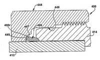
굴곡 상쇄 특징부는 이음쇠 본체에도 마련되어, 튜브 단부와 이음쇠 본체 간의 반경 방향 반력을 감소시키고, 이에 따라 이음쇠 해체중에 이음쇠 본체로부터 튜브 단부를 분리하는 데 기여할 수 있다. 도 15 및 도 16에는 굴곡 상쇄 특징부를 포함하는 예시적인 이음쇠 조립체(800)가 도시되어 있다. 이음쇠 조립체(800)는 튜브 단부(874)를 수용하는 소켓(810)을 지닌 이음쇠 본체(814)를 포함한다. 소켓은 환형 길이 방향 벽면(812)과, 이 환형 길이 방향 벽면(812)의 축방향 내측 단부로부터 축방향으로 그리고 반경 방향 내측으로 연장되는 축방향으로 쑥 들어간 견부면(815)을 포함한다. 이음쇠 조립체(800)는 도 1의 이음쇠(10)의 구동 너트(44) 및 페룰(80, 82)과 일치- 필수적인 것은 아님 -할 수 있는 구동 너트(844)와 페룰(880, 882)을 더 포함할 수 있다.Flexural offset features may also be provided in the fitting body to reduce the radial reaction between the tube end and the fitting body, thereby contributing to separating the tube end from the fitting body during fitting disassembly. 15 and 16 illustrate an example
이음쇠 본체(814)는 이음쇠의 핑거 타이트 상태에서 또는 튜브 단부(874)의 축방향 압박 이전에 튜브 단부(874)가 견부면(815)의 외측부와 맞물리거나 맞닿게 튜브 단부(874)를 수용하도록 구성될 수 있다. 다른 실시예에서, 튜브 단부(874)는 이음쇠의 핑거 타이트 상태에서 테이퍼진 튜브 포획면(852)과 맞물려, 도 15에 도시한 바와 같이 견부면(815)과 튜브 단부(874)에 공간이 형성될 수 있다. 이음쇠 조립체(800)를 풀업할 때, 도 16에 도시한 바와 같이 튜브 단부(874)는 축방향으로 압박되어 견부면(815)과 맞물리고, 이 때 축방향으로 쑥 들어간 견부면(815)과 튜브 단부(874)의 내측부(876) 사이의 간극(G)이 튜브 단부(874)의 추가의 축방향 압박을 허용하여 내측 방향 선회력(B)이 생성되며, 이 선회력은 외측 방향 굴곡력(A)을 적어도 부분적으로 상쇄시켜 이음쇠 본체(814)와 튜브 단부(874) 사이의 반경 반향 반력을 감소시키고, 이에 의해 이음쇠의 해체중에 이음쇠 본체(814)로부터 튜브 단부(874)를 분리하는 데 기여한다. 도 14의 이음쇠 설치 공구 다이(700)의 경우와 마찬가지로, 간극(G)은 튜브 단부(874)의 축방향 압박이 튜브 단부(874)의 내측부(876)를 추가로 축방향으로 지지하게 되도록 제한될 수 있다.The
전술한 공구 다이(700)의 경우와 마찬가지로, 이음쇠 본체(814)의 소켓(810)은 필수적인 것은 아니지만, 예컨대 도 1 내지 도 6의 예시적인 실시예에 도시한 바와 같이, 예컨대 튜브 단부(874)와 이음쇠 본체(814) 간의 반경 방향 반력을 감소시키는 및/또는 축방향 반력을 증가시키는 단차면, 테이퍼진 면 또는 오목한 환형 길이 방향 면과 같은, 본 명세서에서 설명한 하나 이상의 다른 특징부를 사용하여 이음쇠 본체(814)로부터 튜브 단부(874)를 분리하는 것을 용이하게 하도록 더욱 구성될 수 있다.As in the case of the tool die 700 described above, the
본 명세서에서는 예시적인 실시예에서 조합하여 구현되는 바와 같은 본 발명의 다양한 양태, 개념 및 특징부를 설명하고 예시할 수 있지만, 이들 다양한 양태, 개념 및 특징부는 많은 변형예에서 개별적으로 또는 이들의 다양한 조합 및 하위 조합으로 사용될 수 있다. 본원에서 일부러 배제하지 않는다면, 그러한 모든 조합 및 하위 조합은 본 발명의 범위 내에 속하는 것으로 의도된다. 또한, 본 명세서에서는 다른 재료와, 구조와, 구성과, 방법과, 회로와, 장치 및 구성 요소와, 소프트웨어와, 하드웨어와, 제어 로직, 그리고 형태, 피트 및 기능에 관한 대안 등과 같은 본 발명의 다양한 양태, 개념 및 특징에 관한 다양한 변형예를 설명할 수 있지만, 그러한 설명은 현재 알려져 있거나 차후에 개발될 이용 가능한 변형예 전부 또는 이러한 변형예를 총망라하는 것으로 의도되지 않는다. 당업자라면 본 발명의 양태, 개념 또는 특징 중 하나 이상을 추가의 실시예에 용이하게 채택할 수 있고, 그러한 변형예가 본 명세서에 개시되어 있지 않은 경우에도 본 발명의 범위 내에서 사용할 수 있다. 추가로, 본 명세서에서는 본 발명의 몇몇 특징, 개념 또는 양태를 바람직한 구성 또는 방법으로서 설명할 수 있지만, 그러한 설명은 별도의 언급이 없다면 그러한 특징이 규정된 것이거나 필수적이라는 것을 시사하도록 의도되는 것은 아니다. 또한, 예시적인 또는 대표적인 수치 및 범위가 본 개시물의 이해를 돕기 위해 포함될 수 있다. 그러나, 그러한 수치 및 범위는 제한적인 의미로 해석되는 것이 아니라, 별도의 언급이 있는 경우에만 중요한 수치 또는 범위로 의도되는 것이다. 더욱이, 다양한 양태, 특징 및 개념은 본 명세서에서 본 발명의 것으로 또는 본 발명의 일부를 형성하는 것으로 명확히 식별될 수 있지만, 그러한 식별은 배타적인 것으로 의도되는 것이 아니라, 오히려 그러한 특정 발명 또는 특정 발명의 부분으로서 명확히 식별되는 일 없이 본 명세서에서 충분히 설명된 본 발명의 양태, 개념 및 특징일 수 있으며, 그 대신에 본 발명은 첨부된 청구 범위에 설명되어 있다. 예시적인 방법 또는 과정에 관한 설명은 모든 경우에 요구되는 모든 단계를 포함하는 것으로 의도되지 않을뿐더러, 제시된 단계들의 순서는 별도의 언급이 없다면 규정된 것으로 혹은 필수적인 것으로 해석되어서는 안된다.While various aspects, concepts, and features of the present invention may be described and illustrated herein as implemented in combination in exemplary embodiments, these various aspects, concepts, and features may be individually or in various combinations thereof in many variations. And sub-combinations. Unless expressly excluded herein, all such combinations and subcombinations are intended to fall within the scope of the present invention. In addition, the specification also includes other materials, structures, configurations, methods, circuits, devices, and components, software, hardware, control logic, and alternatives to forms, fits, and functions, and the like. While various modifications may be made in terms of various aspects, concepts, and features, such descriptions are not intended to be exhaustive of all or all of the available variations currently known or later developed. One skilled in the art can readily adopt one or more of the aspects, concepts, or features of the present invention in further embodiments, and can be used within the scope of the present invention even if such variations are not disclosed herein. In addition, although some features, concepts, or aspects of the invention may be described herein as a preferred configuration or method, such descriptions are not intended to suggest that such features are defined or essential unless otherwise indicated. . In addition, example or representative values and ranges may be included to aid in the understanding of this disclosure. However, such numbers and ranges are not to be interpreted in a limiting sense, but are intended to be important values or ranges only when otherwise noted. Moreover, although various aspects, features, and concepts may be expressly identified herein as being part of, or forming part of, the present invention, such identification is not intended to be exhaustive, but rather, of the particular or particular invention. It may be aspects, concepts, and features of the invention, as fully described herein, without being clearly identified as part thereof, instead the invention is described in the appended claims. The descriptions of exemplary methods or processes are not intended to include all steps required in all cases, and the order of steps presented should not be construed as defined or essential unless otherwise indicated.
Claims (30)
Translated fromKoreanApplications Claiming Priority (4)
| Application Number | Priority Date | Filing Date | Title |
|---|---|---|---|
| US75868806P | 2006-01-13 | 2006-01-13 | |
| US60/758,688 | 2006-01-13 | ||
| US83454806P | 2006-07-31 | 2006-07-31 | |
| US60/834,548 | 2006-07-31 |
Publications (1)
| Publication Number | Publication Date |
|---|---|
| KR20080091186Atrue KR20080091186A (en) | 2008-10-09 |
Family
ID=38222412
Family Applications (1)
| Application Number | Title | Priority Date | Filing Date |
|---|---|---|---|
| KR1020087018915AWithdrawnKR20080091186A (en) | 2006-01-13 | 2006-12-15 | Fitting for tube or pipe |
Country Status (8)
| Country | Link |
|---|---|
| US (4) | US8007013B2 (en) |
| EP (3) | EP2489913B1 (en) |
| JP (4) | JP5342880B2 (en) |
| KR (1) | KR20080091186A (en) |
| AU (1) | AU2006336580A1 (en) |
| CA (1) | CA2636738C (en) |
| IL (1) | IL192680A0 (en) |
| WO (1) | WO2007087043A2 (en) |
Cited By (3)
| Publication number | Priority date | Publication date | Assignee | Title |
|---|---|---|---|---|
| KR20130119930A (en)* | 2010-10-15 | 2013-11-01 | 스와겔로크 컴패니 | Push to connect conduit fitting with ferrule |
| KR20170043670A (en)* | 2008-12-10 | 2017-04-21 | 스와겔로크 컴패니 | Ferrule assembly for conduit fitting |
| KR20180056808A (en)* | 2010-01-21 | 2018-05-29 | 스와겔로크 컴패니 | Conduit gripping device having retaining structure for conduit fitting |
Families Citing this family (42)
| Publication number | Priority date | Publication date | Assignee | Title |
|---|---|---|---|---|
| KR20080091186A (en) | 2006-01-13 | 2008-10-09 | 스와겔로크 컴패니 | Fitting for tube or pipe |
| WO2009018079A1 (en)* | 2007-07-27 | 2009-02-05 | Swagelok Company | Tapered nut for tube or pipe fitting |
| US20100194107A1 (en)* | 2007-08-09 | 2010-08-05 | Swagelok Company | Tube fitting |
| US8608210B2 (en)* | 2007-09-06 | 2013-12-17 | Insight Engineering Services, Inc. | Coupling device for tubular members |
| KR101845189B1 (en)* | 2009-02-20 | 2018-04-03 | 스와겔로크 컴패니 | Conduit fitting with torque collar |
| WO2010096675A1 (en) | 2009-02-20 | 2010-08-26 | Swagelok Company | Conduit fitting with split torque collar |
| WO2010129261A1 (en) | 2009-04-27 | 2010-11-11 | Swagelok Company | Tapered drive nut for conduit fitting |
| US20120227850A1 (en)* | 2009-09-16 | 2012-09-13 | Arktis Radiation Detectors Ltd. | Tube coupling for connecting an object to one end of a tube in a uhv tight manner and vessel with such a tube coupling |
| GB2481195B (en)* | 2010-06-14 | 2016-01-06 | Agilent Technologies Inc | Fitting element with grip force distributor |
| WO2012006405A2 (en)* | 2010-07-09 | 2012-01-12 | Swagelok Company | Conduit fitting with flexible torque collar |
| US8459700B2 (en)* | 2010-12-21 | 2013-06-11 | Baker Hughes Incorporated | Wet disconnect system with post disconnection pressure integrity |
| US9383049B2 (en)* | 2011-05-02 | 2016-07-05 | Cambridge Brass, Inc. | Universal coupling and parts therefor |
| US9470347B1 (en) | 2011-06-08 | 2016-10-18 | AGS I-Prop., LLC | Fluid line connector |
| JP6202794B2 (en)* | 2011-10-05 | 2017-09-27 | 川澄化学工業株式会社 | Connecting member |
| US20140027074A1 (en) | 2012-07-30 | 2014-01-30 | Brian Houlihan | Safety screen frame |
| EP2870469B1 (en)* | 2012-07-05 | 2020-09-09 | Agilent Technologies, Inc. | Single-piece ferrule joint with undercut tapering part |
| JP5231671B1 (en) | 2012-07-31 | 2013-07-10 | イハラサイエンス株式会社 | Fitting and ferrule manufacturing method thereof |
| US9086176B2 (en)* | 2013-03-18 | 2015-07-21 | Wen Sheng Fu Co. Ltd. | Valve structure |
| EP3011214B1 (en)* | 2013-06-19 | 2019-05-22 | Parker-Hannificn Corporation | High strength flexible ferrule |
| JP6651453B2 (en) | 2013-10-24 | 2020-02-19 | スウエイジロク・カンパニー | Single acting push type connection pipe joint |
| JP6243246B2 (en)* | 2014-02-17 | 2017-12-06 | イハラサイエンス株式会社 | Fittings and ferrules |
| EP3140580B1 (en) | 2014-05-09 | 2020-03-25 | Swagelok Company | Conduit fitting with components adapted for facilitating assembly |
| US9604046B2 (en)* | 2014-11-03 | 2017-03-28 | Nordson Corporation | Protective caps for use with medical fluid fittings, and related methods |
| US10458582B2 (en) | 2015-04-23 | 2019-10-29 | Swagelok Company | Single action push to connect conduit fitting with colleting |
| EP3597979B1 (en) | 2015-04-23 | 2021-09-29 | Swagelok Company | Single action push to connect conduit fitting with colleting |
| WO2017035439A1 (en) | 2015-08-26 | 2017-03-02 | Swagelok Company | Conduit retaining structure for conduit fitting |
| US11067467B2 (en)* | 2015-09-08 | 2021-07-20 | Mécanique Analytique Inc. | Fitting assembly with leak detection for analytical systems |
| WO2017136210A1 (en) | 2016-02-04 | 2017-08-10 | Swagelok Company | Component retaining structure for conduit fitting |
| US10808871B2 (en) | 2016-12-13 | 2020-10-20 | Cantex International, Inc. | High pressure flowline union |
| US10508762B2 (en)* | 2017-03-20 | 2019-12-17 | Brian B. Kim | Assembly of a flexible tube and a fitting body and a method thereof |
| US10520118B2 (en) | 2017-05-11 | 2019-12-31 | Circor International | Tube fitting assembly |
| IT201700078227A1 (en)* | 2017-07-11 | 2019-01-11 | Dromos S R L | Brake control transmission device |
| US10400929B2 (en)* | 2017-09-27 | 2019-09-03 | Quick Fitting, Inc. | Fitting device, arrangement and method |
| CN112166279B (en) | 2018-04-27 | 2022-09-27 | 斯瓦戈洛克公司 | Ferrule assembly for a catheter fitting |
| JP2020139541A (en)* | 2019-02-27 | 2020-09-03 | イハラサイエンス株式会社 | Joint structure |
| CN113518879B (en) | 2019-04-01 | 2023-12-15 | 斯瓦戈洛克公司 | Push-to-connect catheter adapter assembly and apparatus |
| JP7126213B2 (en)* | 2020-05-29 | 2022-08-26 | 東尾メック株式会社 | pipe joint |
| EP3992514B1 (en) | 2019-06-28 | 2024-05-15 | Higashio Mech Co., Ltd. | Pipe joint |
| JP7185885B2 (en)* | 2020-05-29 | 2022-12-08 | 東尾メック株式会社 | pipe joint |
| US10969047B1 (en) | 2020-01-29 | 2021-04-06 | Quick Fitting Holding Company, Llc | Electrical conduit fitting and assembly |
| US11035510B1 (en) | 2020-01-31 | 2021-06-15 | Quick Fitting Holding Company, Llc | Electrical conduit fitting and assembly |
| CN114738567B (en)* | 2022-04-19 | 2024-05-07 | 东莞欧耐思科技有限公司 | Quick plug for airtight test |
Family Cites Families (66)
| Publication number | Priority date | Publication date | Assignee | Title |
|---|---|---|---|---|
| US1595310A (en)* | 1920-01-09 | 1926-08-10 | Adolph Mueller | Compression coupling |
| US2100796A (en)* | 1936-04-02 | 1937-11-30 | Thomas & Betts Corp | Pipe coupler |
| US2351636A (en)* | 1936-05-04 | 1944-06-20 | Teletype Corp | Printing telegraph apparatus |
| US2255673A (en)* | 1940-02-05 | 1941-09-09 | Wagner Malleable Products Comp | Nut |
| US2351363A (en)* | 1942-08-20 | 1944-06-13 | Parker Appliance Co | Coupling for tubes |
| US2554585A (en)* | 1949-01-27 | 1951-05-29 | Albert W Miller | Coupling |
| US2579529A (en)* | 1949-03-01 | 1951-12-25 | George V Woodling | Flareless tube connection |
| US2693374A (en)* | 1950-05-05 | 1954-11-02 | Paul D Wurzburger | Pipe coupling with deformable ring for flareless pipe |
| US2695796A (en)* | 1952-10-29 | 1954-11-30 | George V Woodling | Coupling sleeve connection |
| US2823935A (en)* | 1953-01-23 | 1958-02-18 | Paul D Wurzburger | Pipe coupling with deformable ring for flareless pipe |
| US3075793A (en)* | 1959-06-03 | 1963-01-29 | Crawford Fitting Co | Packed wedge type coupling having positioning means |
| US3139293A (en)* | 1959-10-16 | 1964-06-30 | Imp Eastman Corp | Tube fitting having means to indicate complete assembly positions |
| US3103373A (en)* | 1961-06-29 | 1963-09-10 | Crawford Fitting Co | Controlled phase sequential gripping device |
| US3336058A (en)* | 1964-08-27 | 1967-08-15 | Imp Eastman Corp | Thermal shock resistant fitting |
| US3321947A (en) | 1965-09-13 | 1967-05-30 | Hoke Mfg Company Inc | Pipe coupling and method of making |
| US3402949A (en)* | 1966-06-06 | 1968-09-24 | Hoke Mfg Company Inc | Stepped connector body |
| US3445128A (en)* | 1967-04-10 | 1969-05-20 | Hoke Inc | Tube coupling having dual ferrule gripping elements with stop means |
| US3695647A (en)* | 1970-07-16 | 1972-10-03 | Hoke Inc | Pipe coupling |
| CA961888A (en)* | 1971-04-15 | 1975-01-28 | Leonard P. Spontelli | Tube fitting |
| US3794362A (en)* | 1972-10-16 | 1974-02-26 | Electrical Fittings Corp | Raintight connector for electrical conduit |
| GB1499215A (en) | 1974-06-05 | 1978-01-25 | Firestone Tire & Rubber Co | Catalysis of amine curable polymers by high dielectric constant compounds |
| US4063760A (en)* | 1976-10-27 | 1977-12-20 | The Weatherhead Company | Quick connect coupling |
| US4304422A (en)* | 1980-02-19 | 1981-12-08 | Gould Inc. | Tube coupling with frangible sleeve |
| DE3203857C2 (en)* | 1982-02-03 | 1984-08-02 | Mannesmann AG, 4000 Düsseldorf | Oil field pipe connection and method of connecting oil field pipes |
| US4489963A (en)* | 1982-04-13 | 1984-12-25 | Otis Engineering Corporation | Pipe joint |
| US4433862A (en)* | 1982-04-13 | 1984-02-28 | Otis Engineering Corporation | Pipe joint |
| JPS61112886A (en)* | 1984-11-08 | 1986-05-30 | 東洋バルヴ株式会社 | Method of bonding pipe |
| US4878698A (en)* | 1987-01-12 | 1989-11-07 | Gilchrist R Fowler | Restraining pipe joint |
| US4915427A (en)* | 1987-12-10 | 1990-04-10 | Crawford Fitting Co. | Coupling device for heavy-walled tubular members |
| US4826218A (en)* | 1987-12-10 | 1989-05-02 | Crawford Fitting Co. | Coupling device for heavy-walled tubular members |
| US5217261A (en)* | 1990-04-23 | 1993-06-08 | Aeroquip Corporation | Flareless compression fitting |
| US5074599A (en) | 1990-10-30 | 1991-12-24 | Crawford Fitting Co. | Tube fitting |
| FR2683609B1 (en)* | 1991-11-07 | 1995-01-20 | Pont A Mousson | LOCKED GASKET FOR PIPES. |
| DE19736765A1 (en) | 1996-06-27 | 1999-02-25 | Friatec Ag | Plug-in connection for pipes |
| US5725259A (en)* | 1996-12-19 | 1998-03-10 | Dials; Carroll P. | Conduit coupling |
| US5882050A (en)* | 1997-04-15 | 1999-03-16 | Williams; Peter C. | Ferrule with relief to reduce galling |
| JP4096392B2 (en) | 1998-02-17 | 2008-06-04 | ダイキン工業株式会社 | Pipe structure including strainer and electric valve unit |
| EP1216377B1 (en) | 1999-09-13 | 2007-04-18 | Swagelok Company | Tube fitting with indicating means |
| US6279242B1 (en) | 1999-09-13 | 2001-08-28 | Swagelok Company | Intrinsic gauging for tube fittings |
| IL148639A0 (en) | 1999-09-22 | 2002-09-12 | Swagelok Co | Apparatus for swaging ferrules |
| US20020079702A1 (en)* | 2000-01-19 | 2002-06-27 | Witzenmann Gmbh Metallschlauch-Fabrik Pforzheim | Flexible conduit element with a connection device attached to at least one end |
| US7108289B1 (en)* | 2000-06-08 | 2006-09-19 | United States Pipe And Foundry Company, Llc | Restraining gasket for mechanical joints of pipes |
| US7104573B2 (en)* | 2000-06-08 | 2006-09-12 | United States Pipe And Foundy Company, Llc | Energized restraining gasket for mechanical joints of pipes |
| DE10034461A1 (en)* | 2000-07-15 | 2002-01-31 | Bosch Gmbh Robert | Procedure for determining visibility |
| ATE398256T1 (en)* | 2001-02-06 | 2008-07-15 | Swagelok Co | PIPE JOINT FOR STAINLESS STEEL PIPES |
| US7407196B2 (en) | 2003-08-06 | 2008-08-05 | Swagelok Company | Tube fitting with separable tube gripping device |
| ES2248536T3 (en)* | 2001-03-09 | 2006-03-16 | The Gates Corporation | QUICK CONNECTION PLUG. |
| US6851729B2 (en)* | 2001-12-07 | 2005-02-08 | Parker-Hannifin Corporation | Tube fitting for medium pressure applications |
| JP2003232474A (en)* | 2002-02-08 | 2003-08-22 | Nasco Fitting Kk | Pipe joint |
| DE10206684B4 (en)* | 2002-02-18 | 2007-06-28 | Peter Pisinger | Compression fittings |
| US7431351B2 (en)* | 2002-04-26 | 2008-10-07 | Russell Larry R | Pressure-containing tubular connections for remote operation |
| JP4145183B2 (en)* | 2003-04-02 | 2008-09-03 | ナスコフィッティング株式会社 | Pipe fitting |
| US7032935B1 (en)* | 2003-04-08 | 2006-04-25 | David Levy | Self energizing connector |
| US6945570B2 (en)* | 2003-05-19 | 2005-09-20 | S & B Technical Products, Inc. | Self restraining gasket and pipe joint |
| US7125054B2 (en)* | 2003-05-19 | 2006-10-24 | S & B Technical Products, Inc. | Self restraining gasket and pipe joint |
| US20050035593A1 (en)* | 2003-08-13 | 2005-02-17 | Delbert Auray | Electrical connection assembly with unitary sealing and compression ring |
| EP1682804A1 (en) | 2003-11-03 | 2006-07-26 | Swagelok Company | Fitting for metal pipe and tubing |
| CN1878979A (en)* | 2003-11-03 | 2006-12-13 | 斯瓦戈洛克公司 | Fitting for metal pipe and tubing |
| US7207606B2 (en)* | 2004-04-19 | 2007-04-24 | United States Pipe And Foundry Company, Llc | Mechanical pipe joint, gasket, and method for restraining pipe spigots in mechanical pipe joint bell sockets |
| US7497483B2 (en) | 2004-04-22 | 2009-03-03 | Swagelok Company | Fitting for tube and pipe with cartridge |
| TW200602577A (en)* | 2004-04-22 | 2006-01-16 | Swagelok Co | Fitting for tube and pipe |
| US7484775B2 (en)* | 2004-07-13 | 2009-02-03 | Harold Kennedy, Jr. | Pipe joint restraint |
| CA2585076C (en)* | 2004-10-29 | 2009-12-29 | The Gates Corporation | Quick connect coupling |
| KR20080091186A (en) | 2006-01-13 | 2008-10-09 | 스와겔로크 컴패니 | Fitting for tube or pipe |
| US8439404B2 (en) | 2007-06-26 | 2013-05-14 | Swagelok Company | Conduit connection with sensing function |
| WO2009018079A1 (en) | 2007-07-27 | 2009-02-05 | Swagelok Company | Tapered nut for tube or pipe fitting |
- 2006
- 2006-12-15KRKR1020087018915Apatent/KR20080091186A/ennot_activeWithdrawn
- 2006-12-15EPEP12164314.2Apatent/EP2489913B1/enactiveActive
- 2006-12-15WOPCT/US2006/048072patent/WO2007087043A2/enactiveApplication Filing
- 2006-12-15CACA2636738Apatent/CA2636738C/ennot_activeExpired - Fee Related
- 2006-12-15AUAU2006336580Apatent/AU2006336580A1/ennot_activeAbandoned
- 2006-12-15JPJP2008550316Apatent/JP5342880B2/enactiveActive
- 2006-12-15USUS11/639,529patent/US8007013B2/enactiveActive
- 2006-12-15EPEP12164312.6Apatent/EP2489912B1/enactiveActive
- 2006-12-15EPEP06845637.5Apatent/EP1971799B1/enactiveActive
- 2008
- 2008-07-08ILIL192680Apatent/IL192680A0/enunknown
- 2011
- 2011-08-25USUS13/217,551patent/US20110309615A1/ennot_activeAbandoned
- 2012
- 2012-10-23USUS13/658,147patent/US9033372B2/enactiveActive
- 2013
- 2013-01-22JPJP2013008942Apatent/JP5702810B2/enactiveActive
- 2013-06-13JPJP2013124543Apatent/JP2013224741A/ennot_activeWithdrawn
- 2015
- 2015-04-22USUS14/692,865patent/US20160018030A1/ennot_activeAbandoned
- 2015-04-24JPJP2015088991Apatent/JP5993487B2/enactiveActive
Cited By (5)
| Publication number | Priority date | Publication date | Assignee | Title |
|---|---|---|---|---|
| KR20170043670A (en)* | 2008-12-10 | 2017-04-21 | 스와겔로크 컴패니 | Ferrule assembly for conduit fitting |
| KR20180059572A (en)* | 2008-12-10 | 2018-06-04 | 스와겔로크 컴패니 | Ferrule assembly for conduit fitting |
| KR20180056808A (en)* | 2010-01-21 | 2018-05-29 | 스와겔로크 컴패니 | Conduit gripping device having retaining structure for conduit fitting |
| KR20130119930A (en)* | 2010-10-15 | 2013-11-01 | 스와겔로크 컴패니 | Push to connect conduit fitting with ferrule |
| KR20190104641A (en)* | 2010-10-15 | 2019-09-10 | 스와겔로크 컴패니 | Push to connect conduit fitting with ferrule |
Also Published As
| Publication number | Publication date |
|---|---|
| EP2489912A3 (en) | 2013-08-28 |
| AU2006336580A1 (en) | 2007-08-02 |
| JP5342880B2 (en) | 2013-11-13 |
| JP2009523967A (en) | 2009-06-25 |
| JP2013224741A (en) | 2013-10-31 |
| US20160018030A1 (en) | 2016-01-21 |
| CA2636738C (en) | 2016-11-08 |
| AU2006336580A2 (en) | 2008-10-30 |
| US20110309615A1 (en) | 2011-12-22 |
| JP5702810B2 (en) | 2015-04-15 |
| WO2007087043A3 (en) | 2007-10-04 |
| EP1971799B1 (en) | 2015-02-18 |
| US8007013B2 (en) | 2011-08-30 |
| WO2007087043A2 (en) | 2007-08-02 |
| IL192680A0 (en) | 2009-08-03 |
| EP2489913B1 (en) | 2016-03-30 |
| EP2489912A2 (en) | 2012-08-22 |
| EP2489912B1 (en) | 2016-03-09 |
| EP1971799A2 (en) | 2008-09-24 |
| US20130140815A1 (en) | 2013-06-06 |
| EP2489913A3 (en) | 2013-08-28 |
| JP2013100908A (en) | 2013-05-23 |
| EP2489913A2 (en) | 2012-08-22 |
| CA2636738A1 (en) | 2007-08-02 |
| US20070164563A1 (en) | 2007-07-19 |
| JP5993487B2 (en) | 2016-09-14 |
| JP2015158275A (en) | 2015-09-03 |
| US9033372B2 (en) | 2015-05-19 |
Similar Documents
| Publication | Publication Date | Title |
|---|---|---|
| KR20080091186A (en) | Fitting for tube or pipe | |
| JP5457348B2 (en) | Tapered nut for pipe or pipe fitting with centering | |
| KR102398921B1 (en) | Conduit fitting with components adapted for facilitating assembly | |
| CN102308137B (en) | Ferrule Assemblies for Conduit Fittings | |
| JP2004526911A5 (en) | ||
| JP2009523967A5 (en) | ||
| JP2018514715A (en) | Swage fitting | |
| US10113678B2 (en) | Quick-coupling sliding joints | |
| US7699357B2 (en) | Coupling for tubes | |
| KR20180112824A (en) | Ferrule for conduit fitting | |
| US11703165B2 (en) | Ferrule assembly for conduit fitting | |
| CN106763049A (en) | Push away swollen drawing type flexible fastening connector | |
| US20210148495A1 (en) | Ferrule arrangements for a conduit fitting | |
| MX2008008828A (en) | Fitting for tube or pipe |
Legal Events
| Date | Code | Title | Description |
|---|---|---|---|
| PA0105 | International application | Patent event date:20080731 Patent event code:PA01051R01D Comment text:International Patent Application | |
| PG1501 | Laying open of application | ||
| PC1203 | Withdrawal of no request for examination | ||
| WITN | Application deemed withdrawn, e.g. because no request for examination was filed or no examination fee was paid |