KR20080090667A - Centrifugal force based microfluidic system and bio cartridge for the microfluidic system - Google Patents
Centrifugal force based microfluidic system and bio cartridge for the microfluidic systemDownload PDFInfo
- Publication number
- KR20080090667A KR20080090667AKR1020070033769AKR20070033769AKR20080090667AKR 20080090667 AKR20080090667 AKR 20080090667AKR 1020070033769 AKR1020070033769 AKR 1020070033769AKR 20070033769 AKR20070033769 AKR 20070033769AKR 20080090667 AKR20080090667 AKR 20080090667A
- Authority
- KR
- South Korea
- Prior art keywords
- microfluidic system
- bio cartridge
- centrifugal force
- cartridge
- valve
- Prior art date
- Legal status (The legal status is an assumption and is not a legal conclusion. Google has not performed a legal analysis and makes no representation as to the accuracy of the status listed.)
- Granted
Links
Images


Classifications
- G—PHYSICS
- G01—MEASURING; TESTING
- G01N—INVESTIGATING OR ANALYSING MATERIALS BY DETERMINING THEIR CHEMICAL OR PHYSICAL PROPERTIES
- G01N35/00—Automatic analysis not limited to methods or materials provided for in any single one of groups G01N1/00 - G01N33/00; Handling materials therefor
- G01N35/00029—Automatic analysis not limited to methods or materials provided for in any single one of groups G01N1/00 - G01N33/00; Handling materials therefor provided with flat sample substrates, e.g. slides
- G01N35/00069—Automatic analysis not limited to methods or materials provided for in any single one of groups G01N1/00 - G01N33/00; Handling materials therefor provided with flat sample substrates, e.g. slides whereby the sample substrate is of the bio-disk type, i.e. having the format of an optical disk
- G—PHYSICS
- G01—MEASURING; TESTING
- G01N—INVESTIGATING OR ANALYSING MATERIALS BY DETERMINING THEIR CHEMICAL OR PHYSICAL PROPERTIES
- G01N35/00—Automatic analysis not limited to methods or materials provided for in any single one of groups G01N1/00 - G01N33/00; Handling materials therefor
- G01N35/10—Devices for transferring samples or any liquids to, in, or from, the analysis apparatus, e.g. suction devices, injection devices
- B—PERFORMING OPERATIONS; TRANSPORTING
- B01—PHYSICAL OR CHEMICAL PROCESSES OR APPARATUS IN GENERAL
- B01L—CHEMICAL OR PHYSICAL LABORATORY APPARATUS FOR GENERAL USE
- B01L2300/00—Additional constructional details
- B01L2300/08—Geometry, shape and general structure
- B01L2300/0803—Disc shape
- B—PERFORMING OPERATIONS; TRANSPORTING
- B01—PHYSICAL OR CHEMICAL PROCESSES OR APPARATUS IN GENERAL
- B01L—CHEMICAL OR PHYSICAL LABORATORY APPARATUS FOR GENERAL USE
- B01L2400/00—Moving or stopping fluids
- B01L2400/04—Moving fluids with specific forces or mechanical means
- B01L2400/0403—Moving fluids with specific forces or mechanical means specific forces
- B01L2400/0409—Moving fluids with specific forces or mechanical means specific forces centrifugal forces
- B—PERFORMING OPERATIONS; TRANSPORTING
- B01—PHYSICAL OR CHEMICAL PROCESSES OR APPARATUS IN GENERAL
- B01L—CHEMICAL OR PHYSICAL LABORATORY APPARATUS FOR GENERAL USE
- B01L2400/00—Moving or stopping fluids
- B01L2400/06—Valves, specific forms thereof
Landscapes
- Physics & Mathematics (AREA)
- Health & Medical Sciences (AREA)
- Life Sciences & Earth Sciences (AREA)
- Chemical & Material Sciences (AREA)
- Analytical Chemistry (AREA)
- Biochemistry (AREA)
- General Health & Medical Sciences (AREA)
- General Physics & Mathematics (AREA)
- Immunology (AREA)
- Pathology (AREA)
- Automatic Analysis And Handling Materials Therefor (AREA)
Abstract
Translated fromKoreanDescription
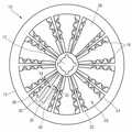
Translated fromKorean도 1은 본 발명의 바람직한 제1 실시예에 따른 미세유동 시스템을 도시한 분해 사시도이다.1 is an exploded perspective view showing a microfluidic system according to a first preferred embodiment of the present invention.
도 2는 도 1의 미세유동 시스템의 용례(用例)를 설명하기 위한 도면이다.2 is a view for explaining the application (use) of the microfluidic system of FIG.
도 3은 본 발명의 바람직한 제2 실시예에 따른 미세유동 시스템을 도시한 분해 사시도이다.3 is an exploded perspective view showing a microfluidic system according to a second preferred embodiment of the present invention.
도 4는 본 발명의 바람직한 제3 실시예에 따른 미세유동 시스템을 도시한 분해 사시도이다.4 is an exploded perspective view showing a microfluidic system according to a third preferred embodiment of the present invention.
<도면의 주요부분에 대한 부호의 설명> <Description of the symbols for the main parts of the drawings>
10 ...미세유동 시스템12 ...스핀들 모터10 ...
14 ...외부 에너지원15 ...프레임14 ...
18 ...격벽20 ...셀(cell)18
22 ...후크(hook)24 ...브라켓22
30 ...바이오 카트리지33 ...밸브30 ...
36 ...채널38 ...더미 카트리지36 ... Channel 38 ... Dummy Cartridge
본 발명은 미세유체공학(microfluidics) 분야에서 사용되는 원심력 기반의 미세유동 시스템에 관한 것이다.The present invention relates to centrifugal force-based microfluidic systems used in the field of microfluidics.
일반적으로 미세유체공학 분야에서 소량의 유체를 이용한 작업에 사용되는 미세유동 구조물에는 소량의 유체를 가두어 둘 수 있는 챔버와, 유체가 흐를 수 있는 채널, 유체의 흐름을 조절할 수 있는 밸브, 및 유체를 받아 소정의 기능을 수행할 수 있는 여러 가지 기능성 유닛 등이 포함될 수 있다. 소형의 칩(chip) 상에서 생화학적 반응을 포함한 시험을 수행할 수 있도록 제작된 장치를 바이오칩(bio-chip)이라 하고, 특히 여러 단계의 처리 및 조작을 하나의 칩에서 수행할 수 있도록 제작된 장치를 랩온어칩(lab-on-a-chip)이라 한다.In general, microfluidic structures used for working with a small amount of fluid in the field of microfluidics include a chamber capable of confining a small amount of fluid, a channel through which the fluid flows, a valve for regulating the flow of fluid, and a fluid. And various functional units capable of receiving a predetermined function. A device designed to perform a test including a biochemical reaction on a small chip is called a bio-chip, and a device designed to perform several steps of processing and manipulation on a single chip. This is called a lab-on-a-chip.
미세유동 구조물 내에서 유체를 이송하기 위해서는 구동 압력이 필요한데, 구동 압력으로서 모세관압이 이용되기도 하고, 별도의 펌프에 의한 압력이 이용되기도 한다. 최근에는 디스크 형상의 플랫폼에 미세유동 구조물을 배치하여 원심력을 이용하는 원심력 기반의 미세유동 장치들이 제안되고 있다. 이를 일컬어 랩씨디(Lab CD) 또는 랩온어씨디(Lab-on-a-CD)라 하기도 한다.The driving pressure is required to transfer the fluid in the microfluidic structure. Capillary pressure may be used as the driving pressure, or a pressure by a separate pump may be used. Recently, microfluidic devices based on centrifugal force using a centrifugal force by disposing a microfluidic structure on a disk-shaped platform have been proposed. This is also known as a Lab CD or a Lab-on-a-CD.
이러한 원심력 기반의 미세유동 장치는 챔버에서 예컨대, 면역 혈청 검사, 유전자 검사 등과 같은 고유한 용도에 따른 시료의 반응이 수행된다. 통상적으로, 원심력 기반의 미세유동 장치는 같은 종류의 검사를 복수 회 수행하거나, 서로 다 른 종류의 검사를 복수 회 수행할 수 있도록 복수 개의 검사 유닛을 포함한다. 그런데, 복수 개의 검사 유닛 가운데 일부만 사용되는 경우, 사용되지 않은 검사 유닛을 포함하고 있는 미세유동 장치를 폐기하는 것은 자원 낭비의 문제를 초래한다. 한편, 상기 미세유동 장치를 폐기하지 않고 나머지 검사 유닛을 사용하기 위해 보관하는 경우 이미 사용된 검사 유닛으로 인해 오염이 유발될 수 있으며, 오염이 유발되지는 않았다 하더라도 이미 사용된 검사 유닛에 잔존하는 시료로 인해 시료 제공자나 시험 수행자가 불쾌감 내지 거부감을 느낄 수 있다는 문제점이 있다.This centrifugal force-based microfluidic device is subjected to reaction of a sample according to a unique use in a chamber, for example, an immunoserum test, a genetic test, or the like. Typically, the centrifugal force-based microfluidic device includes a plurality of inspection units to perform the same kind of inspection a plurality of times or to perform a different kind of inspection a plurality of times. By the way, when only a part of the plurality of inspection units are used, discarding the microfluidic device including the unused inspection unit causes a problem of resource waste. On the other hand, when the microfluidic device is stored without using the remaining test unit, contamination may be caused by the test unit that is already used, and the sample remaining in the test unit that is already used even if the contamination is not caused. There is a problem that the sample provider or test performer may feel unpleasant or rejection.
또한, 디스크 형태의 미세유동 장치를 제조함에 있어 복수 장의 기판이 초음파 융착 등의 방법에 의해 접착되는데 접착 면적이 클수록 접착이 어렵고 불량도 많아진다는 문제점이 있다.In addition, in the manufacture of a disk-type microfluidic device, a plurality of substrates are bonded by a method such as ultrasonic fusion, but there is a problem that the larger the adhesion area, the more difficult the adhesion and the more defects.
본 발명은 상기한 문제점을 해결하기 위한 것으로, 하나의 검사 유닛을 포함한 바이오 카트리지(bio cartridge)와 이를 포함하는 원심력 기반의 미세유동 시스템을 제공하는 것을 기술적 과제로 한다.The present invention is to solve the above problems, to provide a bio cartridge (bio cartridge) including a test unit and a centrifugal force-based microfluidic system comprising the same as a technical problem.
상기한 기술적 과제를 달성하기 위하여 본 발명은, 스핀들 모터; 격벽에 의해 구분된 복수의 셀(cell)을 구비하고, 상기 스핀들 모터에 착탈 가능하게 장착되어 회전하는 프레임; 및, 상기 복수의 셀 중에서 적어도 하나에 착탈 가능하게 탑재되는 바이오 카트리지(bio cartridge);를 구비하고, 상기 바이오 카트리지는 유체를 수용하기 위한 챔버(chamber), 유체를 이송하기 위한 채널(channel), 및 유체 의 흐름을 제어하기 위한 밸브(valve)를 구비한 것을 특징으로 하는 원심력 기반의 미세유동 시스템과, 상기 미세유동 시스템용 바이오 카트리지를 제공한다.The present invention to achieve the above technical problem, the spindle motor; A frame having a plurality of cells separated by a partition wall, the frame being detachably mounted to the spindle motor and rotating; And a bio cartridge detachably mounted in at least one of the plurality of cells, wherein the bio cartridge comprises a chamber for receiving a fluid, a channel for transporting the fluid, And it provides a centrifugal force-based microfluidic system, characterized in that it has a valve for controlling the flow of the fluid, and a bio cartridge for the microfluidic system.
바람직하게는, 상기 밸브는 상전이 물질(phase transition material) 및, 상기 상전이 물질에 분산된, 외부로부터 공급된 에너지에 의해 발열하는 다수의 미세 발열입자를 포함하며, 상기 미세유동 시스템은 상기 미세 발열입자가 발열하여 그 열에 의해 상기 상전이 물질이 유동 가능하게 상전이 될 수 있게 상기 밸브에 에너지를 공급하는 외부 에너지원을 더 구비할 수 있다.Preferably, the valve includes a phase transition material and a plurality of micro heating particles that generate heat by energy supplied from the outside dispersed in the phase transition material, and the microfluidic system includes the micro heating particles. The apparatus may further include an external energy source for supplying energy to the valve so that the phase change material is flowable so that the phase change material may flow.
바람직하게는, 상기 미세 발열입자는 미세 금속 산화물일 수 있다.Preferably, the fine heating particles may be a fine metal oxide.
바람직하게는, 상기 상전이 물질은 왁스, 겔, 또는 열가소성 수지일 수 있다.Preferably, the phase change material may be a wax, a gel, or a thermoplastic resin.
바람직하게는, 상기 외부 에너지원은 상기 밸브에 전자기파를 조사하도록 구성될 수 있다.Advantageously, said external energy source can be configured to irradiate said valve with electromagnetic waves.
바람직하게는, 상기 미세유동 시스템은 상기 프레임의 회전 밸런스를 조정하기 위하여, 상기 바이오 카트리지가 탑재되는 않은 셀 중에서 적어도 하나에 착탈 가능하게 탑재되는 더미 카트리지(dummy cartridge)를 더 구비할 수 있다.Preferably, the microfluidic system may further include a dummy cartridge detachably mounted in at least one of the cells in which the bio cartridge is not mounted in order to adjust the rotational balance of the frame.
바람직하게는, 상기 셀은 상기 프레임의 회전 중심의 주변에 부채꼴 형상으로 형성되며, 상기 바이오 카트리지는 셀의 형상에 대응되게 부채꼴 형상으로 형성될 수 있다.Preferably, the cell is formed in a fan shape around the center of rotation of the frame, the bio cartridge may be formed in a fan shape corresponding to the shape of the cell.
바람직하게는, 상기 바이오 카트리지를 상기 셀에 착탈 가능하게 고정하는 수단은, 상기 셀의 내측에 마련된 후크(hook)일 수 있다.Preferably, the means for detachably fixing the bio cartridge to the cell may be a hook provided inside the cell.
바람직하게는, 상기 바이오 카트리지를 상기 셀에 착탈 가능하게 고정하는 수단은, 상기 프레임과 체결되어 상기 셀을 폐쇄하는 커버(cover)일 수 있다.Preferably, the means for detachably fixing the bio cartridge to the cell may be a cover that is engaged with the frame to close the cell.
바람직하게는, 상기 바이오 카트리지는 상기 바이오 카트리지에 착탈 가능하게 탑재되는, 특정 물질의 존재 여부를 판독하기 위한 테스트 스트립(test strip)을 포함하는 테스트 키트(test kit)를 더 구비할 수 있다.Preferably, the bio cartridge may further include a test kit including a test strip for reading the presence or absence of a specific substance, which is detachably mounted on the bio cartridge.
이하, 첨부된 도면을 참조하여 본 발명의 바람직한 실시예에 따른 원심력 기반의 미세유동 시스템 및 상기 미세유동 시스템용 바이오 카트리지를 상세하게 설명한다.Hereinafter, with reference to the accompanying drawings will be described in detail the centrifugal force-based microfluidic system and the bio cartridge for the microfluidic system according to a preferred embodiment of the present invention.
도 1은 본 발명의 바람직한 제1 실시예에 따른 미세유동 시스템을 도시한 분해 사시도이고, 도 2는 도 1의 미세유동 시스템의 용례(用例)를 설명하기 위한 도면이다.1 is an exploded perspective view illustrating a microfluidic system according to a first exemplary embodiment of the present invention, and FIG. 2 is a view for explaining an application of the microfluidic system of FIG. 1.
도 1을 참조하면, 본 발명의 바람직한 실시예에 따른 미세유동 시스템(10)은 스핀들 모터(12)와 상기 스핀들 모터(12)에 착탈 가능하게 장착되어 회전하는 프레임(15)과, 상기 프레임(15)에 착탈 가능하게 탑재되는 적어도 하나의 바이오 카트리지(bio cartridge, 30)를 구비한다.Referring to FIG. 1, the
상기 프레임(15)은 중심부에 상기 스핀들 모터(12)가 삽입 장착되는 스핀들 모터 장착공(16)을 구비하고, 상기 중심부에서 방사 방향으로 연장된 복수의 격벽(18)을 구비한다. 또한, 상기 격벽들(18)에 의해 동일한 크기로 구분된 복수의 셀(cell, 20)을 포함한다. 상기 셀(20)은 부채꼴 형상을 가지며, 내측에 바이오 카트리지(30)를 착탈 가능하게 고정하기 위한 후크(hook, 22)와, 바이오 카트리 지(30)를 지지하는 브라켓(24)을 구비한다.The
상기 바이오 카트리지(30)는 상기 프레임(15)에 마련된 복수의 셀(20) 가운데 적어도 하나에 탑재된다. 상기 바이오 카트리지(30)는 셀(20)의 형상에 대응되게 부채꼴 형상이다. 상기 바이오 카트리지(30)를 셀(20)에 삽입하면 상기 브라켓(24)에 의해 바이오 카트리지(30)가 지지되며, 후크(22)에 의해 셀(20) 내에서 이탈되지 않게 고정된다. 상기 후크(22)를 벌리고 상기 바이오 카트리지(30)를 들어올리면 바이오 카트리지(30)를 프레임(15)으로부터 분리할 수 있다.The
상기 바이오 카트리지(30)는 소량의 유체를 수용하기 위한 챔버(chamber)와, 유체를 이송하기 위한 채널(channel)과, 유체의 흐름을 제어하기 위한 밸브(valve)를 구비한다. 구체적으로, 도 1 및 도 2에 도시된 바이오 카트리지(30)는 혈당 측정 검사에 이용되는 것으로, 전혈(WB; whole blood)과 같은 시료를 원심 분리하는 원심 분리 유닛(32)과, 상기 원심 분리 유닛(32)에서 추출된 혈청에 포함된 글루코스(glucose)와 같은 특정 물질과 반응하여 상기 특정 물질의 존재와 그 양을 식별케 하는 반응액(reagent)을 수용하는 반응 챔버(35)를 구비한다. 또한, 상기 원심 분리 유닛(32)과 반응 챔버(35)를 연결하는 채널(36)과 상기 채널(36)을 통한 유체의 흐름을 통제하는 밸브(33)를 구비한다.The
상기 밸브(33)는 상기 채널(36)을 폐쇄하고 있다가 일정한 조건 하에서 개방하는 밸브이다. 상기 밸브는 상온에서 고체 상태인 상전이 물질(phase transition material)과 상기 상전이 물질에 분산된 다수의 미세 발열입자를 포함하여 이루어진다. 상기 상전이 물질은 왁스(wax)일 수 있다. 상기 왁스는 가열되면 용융하여 액체 상태로 변하며, 부피 팽창한다. 상기 왁스로는, 예컨대 파라핀 왁스(paraffin wax), 마이크로크리스탈린 왁스(microcrystalline wax), 합성 왁스(synthetic wax), 또는 천연 왁스(natural wax) 등이 채용될 수 있다.The
한편, 상기 상전이 물질은 겔(gel) 또는 열가소성 수지일 수도 있다. 상기 겔로는 예컨대, 폴리아크릴아미드(polyacrylamide), 폴리아크릴레이트(polyacrylates), 폴리메타크릴레이트(polymethacrylates), 또는 폴리비닐아미드(polyvinylamides) 등이 채용될 수 있으며, 열가소성 수지로는 예컨대, COC(cyclic olefin copolymer), PMMA(polymethylmethacrylate), PC(polycarbonate), PS(polystyrene), POM(polyoxymethylene), PFA(perfluoralkoxy), PVC(polyvinylchloride), PP(polypropylene), PET(polyethylene terephthalate), PEEK(polyetheretherketone), PA(polyamide), PSU(polysulfone), 또는 PVDF(polyvinylidene fluoride) 등이 채용될 수 있다.The phase change material may be a gel or a thermoplastic resin. As the gel, for example, polyacrylamide, polyacrylates, polymethacrylates, polyvinylamides, and the like may be employed. As the thermoplastic resin, for example, COC (cyclic olefin copolymer, polymethylmethacrylate (PMMA), polycarbonate (PC), polystyrene (PS), polyoxymethylene (POM), perfluoralkoxy (PFA), polyvinylchloride (PVC), polypropylene (PP), polyethylene terephthalate (PET), polyetheretherketone (PEEK), Polyamide (PA), polysulfone (PSU), polyvinylidene fluoride (PVDF), or the like may be employed.
상기 미세 발열입자는 대략 0.1 mm 정도의 깊이(D)를 갖는 채널(36)을 자유롭게 통과할 수 있도록 수십 내지 수백 나노미터(nm)의 직경을 갖는다. 상기 미세 발열입자는 예컨대, 레이저빔 조사 등과 같은 방법으로 에너지가 공급되면 그 에너지에 의해 온도가 급격히 상승하여 발열하는 성질을 갖는다. 상기 미세 발열입자는 예컨대, 산화철과 같은 강자성(强磁性)의 미세한 금속 산화물 입자일 수 있다.The micro heating particles have a diameter of tens to hundreds of nanometers (nm) to freely pass through the
상기 미세 발열입자는 캐리어 오일(carrier oil)에 고르게 분산된 상태로 보관될 수 있다. 이 경우 상기 미세 발열입자는 캐리어 오일에 분산될 수 있도록 금속 성분의 코어(core)와, 상기 금속 성분을 감싸는 계면활성성분(surfactant)을 포 함하는 분자 구조를 가질 수 있다. 용융된 상전이 물질에 상기 미세 발열입자가 분산된 캐리어 오일을 부어 혼합하여 밸브용 충전물을 제조할 수 있다. 상기 용융된 밸브용 충전물을 채널(36)에 주입하고 경화시켜 채널(36)을 폐쇄하는 밸브(33)를 형성할 수 있다.The micro heating particles may be stored in a state dispersed evenly in a carrier oil (carrier oil). In this case, the micro heating particle may have a molecular structure including a core of a metal component and a surfactant surrounding the metal component so as to be dispersed in a carrier oil. The filling material for the valve may be prepared by pouring and mixing the carrier oil in which the micro heating particles are dispersed in a molten phase-transfer material. The molten valve filler may be injected into the
상기 밸브(33)에 레이저 조사 등의 방법으로 에너지가 공급되면 미세 발열입자가 급속히 발열하고, 그 열에 의해 상전이 물질이 급속히 용융된다. 이렇게 용융된 밸브(33)는 채널(36) 상에 마련된 드레인(drain, 34)으로 배출되어 채널(36)은 유체의 이송이 가능하게 개방된다. 상기 미세유동 시스템(10)은 상기 밸브(33)에 에너지를 공급하기 위한 외부 에너지원(14)을 구비한다. 상기 외부 에너지원(14)은 상기 밸브(33)에 전자기파를 조사하도록 구성될 수 있다. 구체적으로, 상기 외부 에너지원(14)은 레이저 다이오드(LD: laser diode)와 같은 레이저 광원을 포함하여, 상기 밸브(33)에 레이저를 조사할 수 있게 구성될 수 있다.When energy is supplied to the
상기 바이오 카트리지(30)는 부채꼴 형상의 상측 기판(미도시)과 하측 기판(미도시)을 준비하고, 상측 기판의 저면이나 하측 기판의 상면에 채널, 챔버 등을 형성한 후, 상기 상측 기판과 하측 기판을 접착하여 제조할 수 있다. 상기 바이오 카트리지(30)는 혈당 측정 검사용 유닛을 한 개만 구비하므로, 통상적인 디스크 형태의 미세유동 장치보다 작은 사이즈로 제조될 수 있다. 따라서, 복수 장의 기판간 접착 면적이 통상적인 디스크 형태의 미세유동 장치보다 작아지므로 초음파 융착 등의 방법에 의한 접착 시에 접착 불량이 감소될 수 있다. 상기 바이오 카트리지(30)는 일회용으로 혈당 측정 검사 등과 같은 특정 용도에 한 번 사용된 후에 폐 기된다.The
상기 미세유동 시스템(10)을 이용하여 특정 검사를 수행할 때 도 1에 도시된 바와 같이 프레임(15)에 마련된 셀(20) 전부에 바이오 카트리지(30)를 탑재하고 검사를 수행할 수도 있으나, 도 2에 도시된 바와 같이 일부의 셀(20)에만 바이오 카트리지(30)를 탑재하고 검사를 수행할 수도 있다. 도 2에서는 프레임(15)에 하나의 바이오 카트리지(30)만 탑재된다. 이때 다른 셀(20)들을 비워둔 채로 프레임(15)을 회전시키면 언밸런스(unbalance)로 인하여 신뢰성이 결여된 검사 결과를 얻을 수 있고, 스핀들 모터(12)나 프레임(15)의 고장을 초래할 수도 있다. 따라서, 바이오 카트리지(30)가 탑재된 셀(20)의 반대편에 있는 셀(20)에는 회전 밸런스를 조정하기 위하여 동일한 외형과 중량을 갖는 더미 카트리지(dummy cartridge, 38)를 탑재된다.When performing a specific inspection using the
도 3은 본 발명의 바람직한 제2 실시예에 따른 미세유동 시스템을 도시한 분해 사시도이다.3 is an exploded perspective view showing a microfluidic system according to a second preferred embodiment of the present invention.
도 3을 참조하면, 본 발명의 제2 실시예에 따른 미세유동 시스템(50)은 스핀들 모터(52)와, 상기 스핀들 모터(52)에 착탈 가능하게 장착되어 회전하는 프레임(55)과, 상기 프레임(55)에 착탈 가능하게 탑재되는 적어도 하나의 바이오 카트리지(bio cartridge, 63)와, 상기 프레임(55)에 결합되는 커버(69)를 구비한다.Referring to FIG. 3, the
상기 프레임(55)은 중심부에 상기 스핀들 모터(52)가 삽입 장착되는 스핀들 모터 장착공(56)과, 상기 중심부에서 방사 방향으로 연장된 복수의 격벽(58)과, 상기 격벽들(58)에 의해 동일한 크기로 구분된 복수의 셀(cell, 60)을 포함한다. 상 기 셀(60)은 부채꼴 형상을 가지며, 내측에 바이오 카트리지(63)를 지지하는 브라켓(61)을 구비한다.The
상기 바이오 카트리지(63)는 상기 복수의 셀(60) 가운데 적어도 하나에 탑재된다. 상기 바이오 카트리지(63)는 셀(60)의 형상에 대응되게 부채꼴 형상이다. 상기 바이오 카트리지(63)를 셀(60)에 삽입하면 상기 브라켓(61)에 의해 바이오 카트리지(63)가 지지된다. 상기 프레임(55)의 외주부에는 커버(69)를 프레임(55)에 착탈 가능하게 고정하기 위한 후크(62)가 마련된다. 상기 바이오 카트리지(63)를 셀(60)에 탑재하고 프레임(55)의 상측부에 커버(69)를 밀착시키면 상기 후크(62)에 의해 커버(69)가 프레임(55)의 상측부에 고정되고 셀(60)이 폐쇄되어 바이오 카트리지(63)가 셀(60)에 고정된다. 상기 후크(62)를 벌리고 상기 커버(69)를 프레임(55)에서 분리하면 상기 셀(60)이 개방되므로 바이오 카트리지(55)를 프레임(55)으로부터 분리할 수 있다.The
상기 바이오 카트리지(63)는 소량의 유체를 수용하기 위한 챔버(chamber)와, 유체를 이송하기 위한 채널(channel)과, 유체의 흐름을 제어하기 위한 밸브(valve)를 구비한다. 구체적으로, 도 3에 도시된 바이오 카트리지(60)는 간염 바이러스 검사와 같은 특정 단백질 검사에 이용되는 것이며, 일회용으로 특정 용도에 한 번 사용된 후에 폐기된다. 상기 바이오 카트리지(63)는 전혈(WB; whole blood)과 같은 시료로부터 간염 바이러스와 같은 특정 단백질을 분리해내는 단백질 분리 유닛(64)과, 상기 특정 단백질의 존부(存否)와 그 양을 식별케 하는 기질(substrate)이 수용된 반응 챔버(65)와, 반응과 무관한 잔류물들을 배출하기 위한 웨이스트 챔 버(66)를 구비한다. 또한, 상기 단백질 분리 유닛(64)과 웨이스트 챔버(66)를 연결하는 채널(67)과, 상기 채널(67)을 통한 유체의 흐름을 통제하는 밸브(68)을 구비한다.The
상기 밸브(68)는 개방되어 있는 상기 채널(67)을 일정한 조건 하에서 폐쇄하는 밸브이다. 상기 밸브는 상온에서 고체 상태인 상전이 물질(phase transition material)과 상기 상전이 물질에 분산된 다수의 미세 발열입자를 포함하여 이루어진다. 상기 밸브(68)를 형성하기 위한 밸브용 충전물의 구성은 도 1의 밸브(33)를 형성하기 위한 밸브용 충전물의 구성과 동일하므로, 중복된 설명은 생략한다. 용융된 밸브용 충전물을 채널(67)에 인접한 수용부에 주입하고 경화시켜 밸브(68)를 형성할 수 있다.The
상기 밸브(68)에 레이저 조사 등의 방법으로 에너지가 공급되면 미세 발열입자가 급속히 발열하고, 그 열에 의해 상전이 물질이 급속히 용융된다. 이렇게 용융된 밸브(68)는 채널(67)로 유입되어 경화되므로 상기 채널(67)은 유체의 이송이 불가능하게 폐쇄된다. 상기 미세유동 시스템(50)은 상기 밸브(68)에 에너지를 공급하기 위한 외부 에너지원(54)을 구비한다. 상기 외부 에너지원(54)은 상기 밸브(68)에 전자기파를 조사하도록 구성될 수 있다. 구체적으로, 상기 외부 에너지원(54)은 레이저 다이오드(LD: laser diode)와 같은 레이저 광원을 포함하여, 상기 밸브(68)에 레이저를 조사할 수 있게 구성될 수 있다.When energy is supplied to the
도 4는 본 발명의 바람직한 제3 실시예에 따른 미세유동 시스템을 도시한 분해 사시도이다.4 is an exploded perspective view showing a microfluidic system according to a third preferred embodiment of the present invention.
도 4를 참조하면, 본 발명의 제3 실시예에 따른 미세유동 시스템(70)은 스핀들 모터(72)와, 상기 스핀들 모터(72)에 착탈 가능하게 장착되어 회전하는 프레임(75)과, 상기 프레임(75)에 착탈 가능하게 탑재되는 적어도 하나의 바이오 카트리지(bio cartridge, 90)을 구비한다.Referring to FIG. 4, the
상기 프레임(75)은 중심부에 상기 스핀들 모터(72)가 삽입 장착되는 스핀들 모터 장착공(76)과, 상기 중심부에서 방사 방향으로 연장된 복수의 격벽(78)과, 상기 격벽들(78)에 의해 동일한 크기로 구분된 복수의 셀(cell, 80)을 포함한다. 상기 셀(80)은 부채꼴 형상을 가지며, 내측에 바이오 카트리지(90)를 착탈 가능하게 고정하기 위한 후크(hook, 82)와, 바이오 카트리지(90)를 지지하는 브라켓(84)을 구비한다.The
상기 바이오 카트리지(90)는 상기 프레임(75)에 마련된 복수의 셀(80) 가운데 적어도 하나에 탑재된다. 상기 바이오 카트리지(90)는 셀(80)의 형상에 대응되게 부채꼴 형상이다. 상기 바이오 카트리지(90)를 셀(80)에 삽입하면 상기 브라켓(84)에 의해 바이오 카트리지(90)가 지지되며, 후크(82)에 의해 셀(80) 내에서 이탈되지 않게 고정된다. 상기 후크(82)를 벌리고 상기 바이오 카트리지(90)를 들어올리면 바이오 카트리지(90)를 프레임(75)으로부터 분리할 수 있다.The
상기 바이오 카트리지(63)는 소량의 유체를 수용하기 위한 챔버(chamber)와, 유체를 이송하기 위한 채널(channel)과, 유체의 흐름을 제어하기 위한 밸브(valve)를 구비하며, 상기 바이오 카트리지(90)에 착탈 가능하게 탑재되는 테스트 키트(test kit, 96)를 더 구비한다. 구체적으로, 도 4에 도시된 바이오 카트리지(90) 는 전혈(WB; whole blood)과 같은 시료를 원심 분리하는 원심 분리 유닛(92)과, 상기 테스트 키트(96)가 삽입되는 테스트 키트 탑재 홈(98)과, 상기 원심 분리 유닛(92)과 테스트 키트 탑재 홈(98)을 연결하는 채널(95)을 구비한다.The
상기 테스트 키트(96)는 상기 원심 분리 유닛(92)을 통해 추출된 유체에 포함된 특정 물질과 반응하여 상기 특정 물질의 존부와 그 양을 식별케 하는 테스트 스트립(test strip, 97)을 내부에 포함한다. 상기 원심 분리 유닛(92)을 통해 추출된 유체가 채널(95)을 따라 흘러 테스트 키트 탑재 홈(98)에 형성된 아웃렛(99)을 통하여 테스트 키트(96) 내부로 유입되며, 검출을 원하는 특정 물질이 있다면 테스트 스트립(97)이 그 특정 물질과 반응하여 식별 가능하게 변화한다.The
상기 바이오 카트리지(90)는 상기 채널(95)을 통한 유체의 흐름을 통제하는 밸브(93)를 구비한다.The
상기 밸브(93)는 폐쇄되어 있는 상기 채널(95)을 일정한 조건 하에서 개방하는 밸브이다. 상기 밸브는 상온에서 고체 상태인 상전이 물질(phase transition material)과 상기 상전이 물질에 분산된 다수의 미세 발열입자를 포함하여 이루어진다. 상기 밸브(93)를 형성하기 위한 밸브용 충전물의 구성은 도 1의 밸브(33)를 형성하기 위한 밸브용 충전물의 구성과 동일하므로, 중복된 설명은 생략한다. 용융된 밸브용 충전물을 채널(95)에 주입하고 경화시켜 밸브(93)를 형성할 수 있다.The
상기 밸브(93)에 레이저 조사 등의 방법으로 에너지가 공급되면 미세 발열입자가 급속히 발열하고, 그 열에 의해 상전이 물질이 급속히 용융된다. 이렇게 용융된 밸브(93)는 채널(95) 상에 마련된 드레인(drain, 94)으로 배출되어 채널(95)은 유체의 이송이 가능하게 개방된다. 상기 미세유동 시스템(70)은 상기 밸브(93)에 에너지를 공급하기 위한 외부 에너지원(74)을 구비한다. 상기 외부 에너지원(74)은 상기 밸브(93)에 전자기파를 조사하도록 구성될 수 있다. 구체적으로, 상기 외부 에너지원(74)은 레이저 다이오드(LD: laser diode)와 같은 레이저 광원을 포함하여, 상기 밸브(93)에 레이저를 조사할 수 있게 구성될 수 있다.When energy is supplied to the
본 발명은 도면에 도시된 실시예를 참고로 설명되었으나 이는 예시적인 것에 불과하며, 당해 분야에서 통상의 지식을 가진 자라면 이로부터 다양한 변형 및 균등한 타 실시예가 가능함을 이해할 수 있을 것이다. 따라서 본 발명의 진정한 보호범위는 첨부된 특허청구범위에 의해서만 정해져야 할 것이다.Although the present invention has been described with reference to the embodiments shown in the drawings, this is merely exemplary, and it will be understood by those skilled in the art that various modifications and equivalent other embodiments are possible. Therefore, the true scope of protection of the present invention should be defined only by the appended claims.
본 발명에 의하면, 종래의 디스크형 미세유동 장치의 경우와 달리 생화학 검사를 수행함에 있어서 검사에 사용된 바이오 카트리지만을 개별적으로 폐기할 수 있으므로, 자원 낭비를 막을 수 있다. 또한, 위생적인 생화학 검사가 가능하여 시료 제공자가 검사 수행자가 불쾌감 내지 거부감을 느끼지 않게 된다.According to the present invention, unlike in the case of the conventional disk-type microfluidic device, only bio cartridges used in the test can be individually disposed in performing the biochemical test, thereby preventing waste of resources. In addition, hygienic biochemical testing is possible so that the sample provider does not feel uncomfortable or rejected by the test taker.
또한, 본 발명의 바이오 카트리지는 통상적인 디스크 형태의 미세유동 장치보다 작은 사이즈로 제조될 수 있으므로, 복수 장의 기판을 접착하여 바이오 카트리지를 제조할 때 접착 면적이 작아서 접착 불량이 감소될 수 있다.In addition, since the bio cartridge of the present invention may be manufactured in a smaller size than a conventional disk-type microfluidic device, when the bio cartridge is manufactured by adhering a plurality of substrates, the adhesion area may be reduced due to a small adhesion area.
Claims (16)
Translated fromKoreanPriority Applications (1)
| Application Number | Priority Date | Filing Date | Title |
|---|---|---|---|
| KR1020070033769AKR101239764B1 (en) | 2007-04-05 | 2007-04-05 | Centrifugal force based microfluidic system and bio cartridge for the microfluidic system |
Applications Claiming Priority (1)
| Application Number | Priority Date | Filing Date | Title |
|---|---|---|---|
| KR1020070033769AKR101239764B1 (en) | 2007-04-05 | 2007-04-05 | Centrifugal force based microfluidic system and bio cartridge for the microfluidic system |
Publications (2)
| Publication Number | Publication Date |
|---|---|
| KR20080090667Atrue KR20080090667A (en) | 2008-10-09 |
| KR101239764B1 KR101239764B1 (en) | 2013-03-06 |
Family
ID=40151729
Family Applications (1)
| Application Number | Title | Priority Date | Filing Date |
|---|---|---|---|
| KR1020070033769AActiveKR101239764B1 (en) | 2007-04-05 | 2007-04-05 | Centrifugal force based microfluidic system and bio cartridge for the microfluidic system |
Country Status (1)
| Country | Link |
|---|---|
| KR (1) | KR101239764B1 (en) |
Cited By (8)
| Publication number | Priority date | Publication date | Assignee | Title |
|---|---|---|---|---|
| CN101893525A (en)* | 2010-07-19 | 2010-11-24 | 中国科学院长春光学精密机械与物理研究所 | A centrifugal double-channel trace liquid quantitative sampling device and its manufacturing method |
| KR101157177B1 (en)* | 2008-11-27 | 2012-06-20 | 삼성전자주식회사 | System and method for processing target material |
| WO2020010913A1 (en)* | 2018-07-12 | 2020-01-16 | 上海速创诊断产品有限公司 | Microfluidic detection chip and manufacturing method therefor, fixing device, and centrifugal detection device |
| WO2021172792A1 (en)* | 2020-02-26 | 2021-09-02 | 주식회사 클리노믹스 | Fluid control device using centrifugal force |
| CN113769800A (en)* | 2021-09-13 | 2021-12-10 | 大连理工大学 | Reagent isolation structure for centrifugal micro-fluidic chip and manufacturing method |
| CN114509575A (en)* | 2022-04-19 | 2022-05-17 | 天津德祥生物技术有限公司 | Microfluidic detection device |
| US20220314238A1 (en)* | 2019-10-02 | 2022-10-06 | Clinomics Inc. | Chamber for centrifuge and centrifuge comprising same |
| CN117531554A (en)* | 2023-11-10 | 2024-02-09 | 成都斯马特科技有限公司 | Microfluidic fan-shaped biochemical reagent disk assembly and application method thereof |
Families Citing this family (4)
| Publication number | Priority date | Publication date | Assignee | Title |
|---|---|---|---|---|
| KR101642434B1 (en) | 2016-01-21 | 2016-07-25 | 주식회사 랩 지노믹스 | Apparatus including cartridge for in-vitro diagnostic bio-material |
| KR102274523B1 (en)* | 2019-12-16 | 2021-07-08 | 전남대학교산학협력단 | Cartridge Type Microfluidic Device |
| KR102731455B1 (en)* | 2021-03-31 | 2024-11-18 | 주식회사 씨티셀즈 | Split disk apparatus |
| WO2024039071A1 (en)* | 2022-08-16 | 2024-02-22 | 경희대학교 산학협력단 | Rotary microfluidic device, rotary microfluidic assembly, nanoparticle synthesis system, metal nanoparticle preparation method, metal nanoparticles prepared therefrom, and surface-enhanced raman scattering substrate |
Family Cites Families (3)
| Publication number | Priority date | Publication date | Assignee | Title |
|---|---|---|---|---|
| CA2239613A1 (en) | 1995-12-05 | 1997-06-12 | Alec Mian | Devices and methods for using centripetal acceleration to drive fluid movement in a microfluidics system with on-board informatics |
| US6632399B1 (en)* | 1998-05-22 | 2003-10-14 | Tecan Trading Ag | Devices and methods for using centripetal acceleration to drive fluid movement in a microfluidics system for performing biological fluid assays |
| KR100618121B1 (en)* | 2004-08-24 | 2006-08-30 | 한국과학기술연구원 | Microparticle Separation Method and Apparatus Using Centrifugal Force and Microfluidic Channel |
- 2007
- 2007-04-05KRKR1020070033769Apatent/KR101239764B1/enactiveActive
Cited By (16)
| Publication number | Priority date | Publication date | Assignee | Title |
|---|---|---|---|---|
| KR101157177B1 (en)* | 2008-11-27 | 2012-06-20 | 삼성전자주식회사 | System and method for processing target material |
| US8796029B2 (en) | 2008-11-27 | 2014-08-05 | Samsung Electronics Co., Ltd. | System and method for processing target material |
| CN101893525B (en)* | 2010-07-19 | 2012-04-11 | 中国科学院长春光学精密机械与物理研究所 | Centrifugal double-channel trace liquid quantitative sampling device and manufacturing method thereof |
| CN101893525A (en)* | 2010-07-19 | 2010-11-24 | 中国科学院长春光学精密机械与物理研究所 | A centrifugal double-channel trace liquid quantitative sampling device and its manufacturing method |
| US11123731B2 (en) | 2018-07-12 | 2021-09-21 | Shanghai Igenetec Diagnostics Co., Ltd. | Microfluidic detection chip, preparation method thereof, fixing device and centrifugal detection device |
| WO2020010913A1 (en)* | 2018-07-12 | 2020-01-16 | 上海速创诊断产品有限公司 | Microfluidic detection chip and manufacturing method therefor, fixing device, and centrifugal detection device |
| US20220314238A1 (en)* | 2019-10-02 | 2022-10-06 | Clinomics Inc. | Chamber for centrifuge and centrifuge comprising same |
| KR20210108802A (en)* | 2020-02-26 | 2021-09-03 | 주식회사 클리노믹스 | Centrifugal fluid control device |
| WO2021172792A1 (en)* | 2020-02-26 | 2021-09-02 | 주식회사 클리노믹스 | Fluid control device using centrifugal force |
| US20230090579A1 (en)* | 2020-02-26 | 2023-03-23 | Clinomics Inc. | Fluid control device using centrifugal force |
| EP4112181A4 (en)* | 2020-02-26 | 2023-10-11 | Clinomics Inc. | CENTRIFUGAL FLUID CONTROL DEVICE |
| CN113769800A (en)* | 2021-09-13 | 2021-12-10 | 大连理工大学 | Reagent isolation structure for centrifugal micro-fluidic chip and manufacturing method |
| CN113769800B (en)* | 2021-09-13 | 2022-05-27 | 大连理工大学 | A kind of reagent isolation structure for centrifugal microfluidic chip and manufacturing method |
| CN114509575A (en)* | 2022-04-19 | 2022-05-17 | 天津德祥生物技术有限公司 | Microfluidic detection device |
| CN114509575B (en)* | 2022-04-19 | 2022-06-14 | 天津德祥生物技术有限公司 | Microfluidic detection device |
| CN117531554A (en)* | 2023-11-10 | 2024-02-09 | 成都斯马特科技有限公司 | Microfluidic fan-shaped biochemical reagent disk assembly and application method thereof |
Also Published As
| Publication number | Publication date |
|---|---|
| KR101239764B1 (en) | 2013-03-06 |
Similar Documents
| Publication | Publication Date | Title |
|---|---|---|
| KR101239764B1 (en) | Centrifugal force based microfluidic system and bio cartridge for the microfluidic system | |
| US20110085950A1 (en) | Centrifugal force based microfluidic system and bio cartridge for the microfluidic system | |
| US8333935B2 (en) | Microfluidic device using microfluidic chip and microfluidic device using biomolecule microarray chip | |
| EP2028496B1 (en) | Centrifugal force-based microfluidic device for blood chemistry analysis | |
| JP5908917B2 (en) | A microfluidic test carrier for allocating a certain volume of liquid to partial volumes | |
| US9616424B2 (en) | Centrifugal-based microfluidic apparatus, method of fabricating the same, and method of testing samples using the microfluidic apparatus | |
| US8539823B2 (en) | Microfluidic device and method of loading sample into the microfluidic device | |
| JP6245931B2 (en) | Microfluidic device and target cell concentration method using the same | |
| KR101335726B1 (en) | Disk type microfluidic device for conducting immunoassey and biochemistry analysis simultaneously | |
| CN102472739B (en) | Centrifugal microfluidic devices and the method for detecting the analysis thing from liquid sample | |
| EP2295142B1 (en) | Microfluidic apparatus having fluid container | |
| KR101930610B1 (en) | Rotatable cartridge for analyzing a biological sample | |
| KR101930611B1 (en) | Rotatable cartridge for processing and analyzing a biological sample | |
| US20130196360A1 (en) | Microfluidic device and control method thereof | |
| JP2003270252A (en) | Device and method for using centripetal acceleration for driving flowing movement in micro-hydraulic engineering system | |
| KR20150101307A (en) | Microfluidic device | |
| US20090209752A1 (en) | Device and method for treating or cleaning sample material, in particular nucleic acids | |
| CN106489072A (en) | The rotating cylinder for analyzing biological sample with measuring room | |
| JP7163558B2 (en) | Separation Apparatus and Separation Method, Separation Device, Inspection Apparatus and Inspection Method | |
| EP2781263A2 (en) | Microfluidic Device and Control Method Thereof | |
| KR20140115912A (en) | Microfluidic Device and Control Method thereof | |
| KR101528154B1 (en) | Apparatus for Measuring Cholesterol and Method thereof | |
| KR102424845B1 (en) | Microfluidic apparatus |
Legal Events
| Date | Code | Title | Description |
|---|---|---|---|
| PA0109 | Patent application | Patent event code:PA01091R01D Comment text:Patent Application Patent event date:20070405 | |
| PG1501 | Laying open of application | ||
| A201 | Request for examination | ||
| PA0201 | Request for examination | Patent event code:PA02012R01D Patent event date:20111104 Comment text:Request for Examination of Application Patent event code:PA02011R01I Patent event date:20070405 Comment text:Patent Application | |
| E701 | Decision to grant or registration of patent right | ||
| PE0701 | Decision of registration | Patent event code:PE07011S01D Comment text:Decision to Grant Registration Patent event date:20130102 | |
| GRNT | Written decision to grant | ||
| PR0701 | Registration of establishment | Comment text:Registration of Establishment Patent event date:20130227 Patent event code:PR07011E01D | |
| PR1002 | Payment of registration fee | Payment date:20130228 End annual number:3 Start annual number:1 | |
| PG1601 | Publication of registration | ||
| FPAY | Annual fee payment | Payment date:20160128 Year of fee payment:4 | |
| PR1001 | Payment of annual fee | Payment date:20160128 Start annual number:4 End annual number:4 | |
| FPAY | Annual fee payment | Payment date:20170125 Year of fee payment:5 | |
| PR1001 | Payment of annual fee | Payment date:20170125 Start annual number:5 End annual number:5 | |
| FPAY | Annual fee payment | Payment date:20180130 Year of fee payment:6 | |
| PR1001 | Payment of annual fee | Payment date:20180130 Start annual number:6 End annual number:6 | |
| FPAY | Annual fee payment | Payment date:20190130 Year of fee payment:7 | |
| PR1001 | Payment of annual fee | Payment date:20190130 Start annual number:7 End annual number:7 | |
| FPAY | Annual fee payment | Payment date:20200130 Year of fee payment:8 | |
| PR1001 | Payment of annual fee | Payment date:20200130 Start annual number:8 End annual number:8 | |
| PR1001 | Payment of annual fee | Payment date:20210128 Start annual number:9 End annual number:9 | |
| PR1001 | Payment of annual fee | Payment date:20220127 Start annual number:10 End annual number:10 | |
| PR1001 | Payment of annual fee | Payment date:20230125 Start annual number:11 End annual number:11 | |
| PR1001 | Payment of annual fee | Payment date:20240131 Start annual number:12 End annual number:12 | |
| PR1001 | Payment of annual fee | Payment date:20250121 Start annual number:13 End annual number:13 |