KR20080088637A - Systems and Methods for Applying Reduced Pressure to Cell Culture - Google Patents
Systems and Methods for Applying Reduced Pressure to Cell CultureDownload PDFInfo
- Publication number
- KR20080088637A KR20080088637AKR1020087020110AKR20087020110AKR20080088637AKR 20080088637 AKR20080088637 AKR 20080088637AKR 1020087020110 AKR1020087020110 AKR 1020087020110AKR 20087020110 AKR20087020110 AKR 20087020110AKR 20080088637 AKR20080088637 AKR 20080088637A
- Authority
- KR
- South Korea
- Prior art keywords
- insert
- cell culture
- conduit
- sealing member
- cell
- Prior art date
- Legal status (The legal status is an assumption and is not a legal conclusion. Google has not performed a legal analysis and makes no representation as to the accuracy of the status listed.)
- Granted
Links
Images


Classifications
- C—CHEMISTRY; METALLURGY
- C12—BIOCHEMISTRY; BEER; SPIRITS; WINE; VINEGAR; MICROBIOLOGY; ENZYMOLOGY; MUTATION OR GENETIC ENGINEERING
- C12M—APPARATUS FOR ENZYMOLOGY OR MICROBIOLOGY; APPARATUS FOR CULTURING MICROORGANISMS FOR PRODUCING BIOMASS, FOR GROWING CELLS OR FOR OBTAINING FERMENTATION OR METABOLIC PRODUCTS, i.e. BIOREACTORS OR FERMENTERS
- C12M41/00—Means for regulation, monitoring, measurement or control, e.g. flow regulation
- C12M41/40—Means for regulation, monitoring, measurement or control, e.g. flow regulation of pressure
- C—CHEMISTRY; METALLURGY
- C12—BIOCHEMISTRY; BEER; SPIRITS; WINE; VINEGAR; MICROBIOLOGY; ENZYMOLOGY; MUTATION OR GENETIC ENGINEERING
- C12M—APPARATUS FOR ENZYMOLOGY OR MICROBIOLOGY; APPARATUS FOR CULTURING MICROORGANISMS FOR PRODUCING BIOMASS, FOR GROWING CELLS OR FOR OBTAINING FERMENTATION OR METABOLIC PRODUCTS, i.e. BIOREACTORS OR FERMENTERS
- C12M25/00—Means for supporting, enclosing or fixing the microorganisms, e.g. immunocoatings
- C12M25/02—Membranes; Filters
- C12M25/04—Membranes; Filters in combination with well or multiwell plates, i.e. culture inserts
- C—CHEMISTRY; METALLURGY
- C12—BIOCHEMISTRY; BEER; SPIRITS; WINE; VINEGAR; MICROBIOLOGY; ENZYMOLOGY; MUTATION OR GENETIC ENGINEERING
- C12M—APPARATUS FOR ENZYMOLOGY OR MICROBIOLOGY; APPARATUS FOR CULTURING MICROORGANISMS FOR PRODUCING BIOMASS, FOR GROWING CELLS OR FOR OBTAINING FERMENTATION OR METABOLIC PRODUCTS, i.e. BIOREACTORS OR FERMENTERS
- C12M35/00—Means for application of stress for stimulating the growth of microorganisms or the generation of fermentation or metabolic products; Means for electroporation or cell fusion
- C12M35/04—Mechanical means, e.g. sonic waves, stretching forces, pressure or shear stimuli
Landscapes
- Engineering & Computer Science (AREA)
- Health & Medical Sciences (AREA)
- Chemical & Material Sciences (AREA)
- Life Sciences & Earth Sciences (AREA)
- Wood Science & Technology (AREA)
- Zoology (AREA)
- Organic Chemistry (AREA)
- Bioinformatics & Cheminformatics (AREA)
- Biotechnology (AREA)
- Genetics & Genomics (AREA)
- General Engineering & Computer Science (AREA)
- Biochemistry (AREA)
- Sustainable Development (AREA)
- General Health & Medical Sciences (AREA)
- Microbiology (AREA)
- Biomedical Technology (AREA)
- Analytical Chemistry (AREA)
- Immunology (AREA)
- Mechanical Engineering (AREA)
- Cell Biology (AREA)
- Apparatus Associated With Microorganisms And Enzymes (AREA)
- Micro-Organisms Or Cultivation Processes Thereof (AREA)
Abstract
Description
Translated fromKorean본 발명은 일반적으로 세포 배양물들에 감소된 압력을 가하기 위한 장치 및 방법들에 관한 것이다. 더욱 상세하게는, 본 발명은 배양 배지 흐름(culture media flow)이 제어된 상태의 실제적으로 기밀이 유지되는 인클로져(enclosure) 내의 세포 배양물들에 감소된 압력을 가하는데 사용되는 장치 및 방법들에 관한 것이다.The present invention generally relates to apparatus and methods for applying reduced pressure to cell cultures. More specifically, the present invention relates to apparatus and methods used to apply reduced pressure to cell cultures in an enclosure that is substantially airtight in a controlled state with culture media flow. will be.
국소 음압(topical negative pressure(TNP))의 적용들은, 육아 조직(granulation tissue) 형성을 증진하고, 간질액(interstitial fluid)을 제거하며, 상처를 폐쇄하고, 상처 표면에 마이크로 변형들(microdeformations)을 유도함으로써 상처들을 치료하는데 유익하다. 일반적인 TNP의 적용들에 있어서, 압력차 또는 유체의 유량들과 같은 임의의 파라미터들은 다양할 수도 있다. 그러나, 인 비보(in vivo) 적용들에서의 상처 치료 반응과 특정한 파라미터의 변수들을 상호 관련 짓는 것이, 부족한 제어 환경으로 인해 항상 가능한 것은 아니다. 따라서, 세포 배양물들에 감소된 압력을 가하고 제어된 인 비트로(in vitro) 환경에서의 TNP 적용들에 대한 다른 파라미터들의 효과들을 측정하기 위한 방법 및 장치를 제공하는 것이 바람직하다.Application of topical negative pressure (TNP) promotes granulation tissue formation, removes interstitial fluid, closes the wound, and introduces microdeformations to the wound surface. It is beneficial for treating wounds by induction. In typical TNP applications, any parameters such as pressure differential or flow rates of the fluid may vary. However, it is not always possible to correlate the wound healing response in certain in vivo applications with the parameters of certain parameters due to the poor control environment. Accordingly, it is desirable to provide a method and apparatus for applying reduced pressure to cell cultures and measuring the effects of other parameters on TNP applications in a controlled in vitro environment.
또한 제어된 배양 배지 유량들을 제공하는 것이 가능하고 공기가 세포 배양물에 유입될 가능성을 줄이는 TNP 적용을 위한 방법 및 장치를 제공하는 것은 바람직하다. 이러한 공기 유입은 기질(matrix)을 건조 시킬 수 있고, 그 때문에 의미 있는 데이터를 얻을 수 없게 된다.It would also be desirable to provide a method and apparatus for TNP application that is capable of providing controlled culture medium flow rates and reduces the likelihood of air entering the cell culture. This air inlet can dry the matrix, and thus no meaningful data can be obtained.
임의의 실시예들에 있어서, 세포 배양 시스템은 세포들을 배양하도록 구성되는 실제적으로 기밀이 유지되는 실제적인 기밀 인클로져; 실제적인 기밀 인클로져에 감소된 압력을 제공하도록 구성되고 실제적인 기밀 인클로져와 유체 연통하는 제1도관; 및 실제적인 기밀 인클로져에 배양 배지를 제공하도록 구성되고 실제적인 기밀 인클로져와 유체 연통하는 제2도관을 포함한다. 다른 실시예들에 있어서, 사용 중에 세포 기질(cell matrix)은 실제적인 기밀 인클로져 내에 위치하고, 사용 중에 감소된 압력은 세포 기질의 제1표면에 가해지고 사용 중에 배양 배지는 세포 기질의 제2표면에 가해진다. 다른 실시예들은 실제적인 기밀 인클로져 내에 위치하는 투과성 표면 및/또는 드레싱을 포함한다. 또 다른 실시예들은 실제적인 기밀 인클로져 내에 위치하는 투과성 표면; 실제적인 기밀 인클로져 내에 위치하는 세포 기질; 및 실제적인 기밀 인클로져 내에 위치하는 드레싱(또는 다른 다양한 물질)을 포함하고, 배양 배지는 제2도관에서부터 투과성 표면을 통과하고, 세포 기질을 통과하여, 드레싱을 통과하고, 제1도관으로 흐른다. 임의의 실시예들에 있어서, 투과성 표면은 세포 기질을 지지하고 세포 기질은 투과성 표면과 드레싱 또는 다른 다양한 물질 사이에 위치할 수도 있다.In some embodiments, the cell culture system comprises a substantially hermetic enclosure, which is substantially hermetic, configured to culture the cells; A first conduit configured to provide reduced pressure to the actual hermetic enclosure and in fluid communication with the actual hermetic enclosure; And a second conduit configured to provide the culture medium to the actual hermetic enclosure and in fluid communication with the actual hermetic enclosure. In other embodiments, the cell matrix in use is located in a practical airtight enclosure, the reduced pressure in use is applied to the first surface of the cell matrix and the culture medium in use is applied to the second surface of the cell matrix. Is applied. Other embodiments include permeable surfaces and / or dressings that are located within the actual hermetic enclosure. Still other embodiments include a transmissive surface located within an actual airtight enclosure; Cell substrates located within the actual hermetic enclosure; And dressings (or other various materials) located within the actual hermetic enclosure, wherein the culture medium passes from the second conduit through the permeable surface, through the cell substrate, through the dressing, and into the first conduit. In certain embodiments, the permeable surface supports the cell substrate and the cell substrate may be positioned between the permeable surface and the dressing or other various materials.
다른 실시예들은 플레이트 웰(plate well)에 밀착되도록 구성되고 세포 배양 인서트(cell culture insert)에 밀착되도록 구성되는 주변 실링(sealing) 부재를 포함하고, 여기서 제1실(seal)은 주변 실링 부재와 플레이트 웰 사이에 형성되도록 하고 제2실은 주변 실링 부재와 세포 배양 인서트 사이에 형성되도록 한다. 인서트 실링 조립체는 세포 배양 인서트와 밀착되도록 또한 구성될 수도 있고, 제3실은 인서트 실링 조립체와 세포 배양 인서트 사이에서 형성되도록 한다. 임의의 실시예들에 있어서, 주변 실링 부재는 플레이트 웰의 내부벽 및 세포 배양 인서트의 외부벽과 밀착되도록 구성될 수도 있고, 인서트 실링 조립체는 인서트의 내부벽과 밀착되도록 구성될 수도 있다. 임의의 실시예들에 있어서, 제1도관은 주변 실링 부재를 통과해서 연장될 수도 있고, 배양 배지 공급 시스템은 제1도관과 결합할 수도 있다. 다른 실시예들에 있어서, 제2도관은 주변 실링 부재를 통과해서 연장될 수도 있고, 제3도관은 인서트 실링 조립체를 통과해서 연장될 수도 있다. 임의의 실시예들에 있어서, 저압 소스(source)는 제3도관과 결합할 수도 있고, 제4도관은 인서트 실링 조립체를 통과해서 연장될 수도 있다. 임의의 실시예들에 있어서, 제1실 및 제2실은 각각 억지 끼움에 의해 생성될 수도 있고 주변 실링 부재는 사출 성형에 의해 형성될 수도 있다. 임의의 실시예들에 있어서, 인서트 실링 조립체는 인서트 실링 부재, 인서트 실 링(insert seal ring), 횡단 실링 부재, 및 인서트 매니폴드(manifold)를 포함할 수도 있다. 임의의 실시예들에 있어서, 인서트 실링 부재 및/또는 인서트 매니폴드는 인서트 안으로 가압될 수도 있다. 다른 실시예들에 있어서, 인서트 매니폴드는 인서트 실링 부재 안으로 나사식으로 삽입될 수도 있다. 임의의 실시예들에 있어서, 인서트 실 링은 인서트 실링 부재와 인서트 매니폴드 사이에서 압축될 수도 있고, 인서트 실링 부재는 사출 성형에 의해 형성될 수도 있다. 임의의 실시예들에 있어서, 주변 실링 부재는 플레이트 웰 안으로 가압될 수도 있다.Other embodiments include a peripheral sealing member configured to be in close contact with a plate well and configured to be in close contact with a cell culture insert, wherein the first seal is in contact with the peripheral sealing member. It is to be formed between the plate wells and the second chamber is to be formed between the peripheral sealing member and the cell culture insert. The insert sealing assembly may also be configured to be in close contact with the cell culture insert, with the third chamber being formed between the insert sealing assembly and the cell culture insert. In some embodiments, the peripheral sealing member may be configured to be in close contact with the inner wall of the plate well and the outer wall of the cell culture insert, and the insert sealing assembly may be configured to be in close contact with the inner wall of the insert. In certain embodiments, the first conduit may extend through the peripheral sealing member and the culture medium supply system may be coupled with the first conduit. In other embodiments, the second conduit may extend through the peripheral sealing member and the third conduit may extend through the insert sealing assembly. In some embodiments, the low pressure source may engage a third conduit and the fourth conduit may extend through the insert sealing assembly. In some embodiments, the first chamber and the second chamber may each be produced by interference fit and the peripheral sealing member may be formed by injection molding. In some embodiments, the insert sealing assembly may include an insert sealing member, an insert seal ring, a transverse sealing member, and an insert manifold. In some embodiments, the insert sealing member and / or insert manifold may be pressed into the insert. In other embodiments, the insert manifold may be threaded into the insert sealing member. In some embodiments, the insert seal ring may be compressed between the insert sealing member and the insert manifold, and the insert sealing member may be formed by injection molding. In some embodiments, the peripheral sealing member may be pressed into the plate well.
다른 실시예들은, 실제적으로 기밀이 유지되는 실제적인 기밀 인클로져를 제공하는 단계; 실제적인 기밀 인클로져 내에 세포 기질을 제공하는 단계; 실제적인 기밀 인클로져에 감소된 압력을 제공하는 단계; 및 실제적인 기밀 인클로져에 배양 배지를 제공하는 단계를 포함하는 세포들을 배양하는 방법을 포함한다. 임의의 실시예들에 있어서, 실제적인 기밀 인클로져는 제1표면 및 제2표면을 포함하고, 감소된 압력은 제1표면에 가해지고 배양 배지는 제2표면에 가해진다. 임의의 실시예들에 있어서, 감소된 압력은 저압 소스와 결합되는 제1도관을 경유하여 제공되고 제1도관은 실제적인 기밀 인클로져와 유체 연통한다. 임의의 실시예들에 있어서, 저압 소스는 진공 펌프이다. 배양 배지는 배양 배지 공급 시스템과 결합되는 제2도관을 경유하여 제공될 수도 있고 제2도관은 실제적인 기밀 인클로져와 유체 연통한다.Other embodiments include providing a practical confidential enclosure that is substantially confidential; Providing a cell substrate in an actual airtight enclosure; Providing reduced pressure to the actual hermetic enclosure; And a method of culturing cells comprising providing a culture medium in a practical airtight enclosure. In some embodiments, the actual airtight enclosure comprises a first surface and a second surface, wherein reduced pressure is applied to the first surface and culture medium is applied to the second surface. In some embodiments, the reduced pressure is provided via a first conduit coupled with a low pressure source and the first conduit is in fluid communication with the actual hermetic enclosure. In some embodiments, the low pressure source is a vacuum pump. The culture medium may be provided via a second conduit coupled with the culture medium supply system and the second conduit is in fluid communication with the actual hermetic enclosure.
다른 실시예들은, 플레이트 웰을 포함하고; 세포 배양 인서트를 포함하고; 플레이트 웰과 밀착되도록 구성되고 세포 배양 인서트와 밀착되도록 구성되는 주변 실링 부재를 포함하고, 여기서 주변 실링 부재는 플레이트 웰과의 제1실을 형성하고 세포 배양 인서트와는 제2실을 형성하도록 하고; 그리고 세포 배양 인서트와 밀착되도록 구성되는 인서트 실링 조립체를 포함하고, 여기서 인서트 실링 조립체는 세포 배양 인서트와의 제3실을 형성하도록 하는 세포들을 배양하기 위한 시스템을 포함한다. 임의의 실시예들은 주변 실링 부재를 통과해서 연장되는 제1도관을 포함하고, 제1도관과 결합하는 저압 소스를 포함한다. 임의의 실시예들에 있어서, 제2도관은 인서트 실링 조립체를 통과해서 연장될 수도 있고, 배양 배지 공급 시스템 은 제2도관과 결합할 수도 있다. 또한, 임의의 실시예들은 세포 배양 인서트 안에 세포 기질 및 세포 기질과 인서트 실링 조립체 사이에 드레싱을 포함한다.Other embodiments include plate wells; A cell culture insert; A peripheral sealing member configured to be in close contact with the plate well and configured to be in close contact with the cell culture insert, wherein the peripheral sealing member forms a first chamber with the plate well and a second chamber with the cell culture insert; And an insert sealing assembly configured to be in close contact with the cell culture insert, wherein the insert sealing assembly comprises a system for culturing cells to form a third chamber with the cell culture insert. Certain embodiments include a first conduit extending through the peripheral sealing member and include a low pressure source that engages with the first conduit. In some embodiments, the second conduit may extend through the insert sealing assembly and the culture medium supply system may be coupled with the second conduit. In addition, certain embodiments include a dressing between the cell substrate and the cell substrate and the insert sealing assembly in the cell culture insert.
도 1은 세포 배양 시스템의 제1실시예를 도시하는 단면도이다.1 is a cross-sectional view showing a first embodiment of a cell culture system.
도 2는 세포 배양 인서트(cell culture insert)를 도시하는 사시도이다.FIG. 2 is a perspective view showing cell culture inserts. FIG.
도 3은 주변 실링(sealing) 부재의 일 실시예를 도시하는 사시도이다.3 is a perspective view illustrating one embodiment of a peripheral sealing member.
도 4는 세포 배양 시스템의 일 실시예를 도시하는 개략도이다.4 is a schematic diagram illustrating one embodiment of a cell culture system.
도 5는 도관의 일 실시예를 도시하는 상세도이다.5 is a detailed diagram illustrating one embodiment of a conduit.
도 6은 도 1의 실시예를 포함하는 세포 배양 시스템의 일 실시예를 도시하는 사시도이다.6 is a perspective view illustrating one embodiment of a cell culture system including the embodiment of FIG. 1.
도 7은 세포 배양 시스템의 일 실시예를 도시하는 분해도이다.7 is an exploded view illustrating one embodiment of a cell culture system.
도 8은 도 7의 실시예를 도시하는 단면도이다.8 is a cross-sectional view illustrating the embodiment of FIG. 7.
도 9는 도 7의 실시예를 도시하는 상세 단면도이다.9 is a detailed cross-sectional view illustrating the embodiment of FIG. 7.
도 10은 도 7의 실시예를 도시하는 상측에서 본 사시도이다.FIG. 10 is a perspective view from above showing the embodiment of FIG. 7. FIG.
도 11은 주변 실링 부재의 일 실시예를 도시하는 상측에서 본 사시도이다.11 is a perspective view from above showing one embodiment of a peripheral sealing member.
도 12는 도 11의 실시예를 도시하는 하측에서 본 사시도이다.FIG. 12 is a perspective view from below showing the embodiment of FIG. 11. FIG.
도 13은 도 11의 실시예를 도시하는 단면도이다.FIG. 13 is a sectional view showing the embodiment of FIG.
도 14는 인서트 실링 부재의 일 실시예를 도시하는 상측에서 본 사시도이다.14 is a perspective view from above showing one embodiment of the insert sealing member.
도 15는 도 14의 실시예를 도시하는 하측에서 본 사시도이다.FIG. 15 is a perspective view from below showing the embodiment of FIG. 14; FIG.
도 16은 도 14의 실시예를 도시하는 단면도이다.16 is a cross-sectional view illustrating the embodiment of FIG. 14.
도 17은 인서트 실 링(insert seal ring)의 일 실시예를 도시하는 평면도이다.FIG. 17 is a plan view illustrating one embodiment of an insert seal ring. FIG.
도 18은 도 17의 실시예를 도시하는 단면도이다.18 is a cross-sectional view illustrating the embodiment of FIG. 17.
도 19는 인서트 매니폴드(insert manifold)의 일 실시예를 도시하는 상측에서 본 사시도이다.FIG. 19 is a perspective view from above showing one embodiment of an insert manifold. FIG.
도 20은 도 19의 실시예를 도시하는 상측에서 본 사시도이다.20 is a perspective view from above showing the embodiment of FIG. 19.
도 21은 도 20의 실시예를 도시하는 단면도이다.21 is a cross-sectional view illustrating the embodiment of FIG. 20.
도 22는 인서트 실 조립체의 일 실시예를 도시하는 분해도이다.22 is an exploded view illustrating one embodiment of an insert seal assembly.
도 23은 세포 배양 시스템의 일 실시예를 도시하는 상측에서 본 사시도이다.Fig. 23 is a perspective view from above showing one embodiment of the cell culture system.
도 24는 도 23의 실시예를 도시하는 단면도이다.24 is a cross-sectional view illustrating the embodiment of FIG. 23.
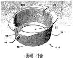
먼저, 도 1 내지 도 4를 참조하면, 세포 배양 시스템(100)은 플레이트 웰(plate well)(10), 여러 세포 배양물들을 성장시키기 위한 세포 배양 용기(20), 및 플레이트 웰(10)과 세포 배양 용기(20) 사이에 위치하는 주변 실링 부재(30)를 포함한다. 이러한 실시예에서, 플레이트 웰(10)은 베이스(12)와 개구 단부(13) 사이에 위치하는 주변 내부벽(11)을 포함한다. 도시된 실시예에서, 세포 배양 용기(20)는 테이퍼(taper)진 몸체(21), 개구 단부(23), 및 내부 경계(29)를 포함하는 데, 테이퍼진 몸체(21)는 한쪽 단부에서 투과성 막(22)에 의해 경계가 지워지는 내부 체적(28) 및 외부벽(19)을 구비하고, 개구 단부(23)는 투과성 막(22)의 반대측에 위치한다. 이러한 실시예에서, 개구 단부(23)는 플랜지(flange)(24) 및 한 쌍의 탭(tab)(26)을 포함하는데, 플랜지(24)는 한 쌍의 노치(25)를 구비하고, 한 쌍의 탭(26)은 상기 노치들(25)과 축방향으로 정렬되어 테이퍼진 몸체(21)로부터 연장된다. 사용 중에, 본 개시된 실시예는 또한 투과성 막(22)과 드레싱(dressing)(45) 사이에 위치하는 세포 기질(cell matrix)(40)을 포함한다. 임의의 실시예들에 있어서, 세포 기질(40)은 다층의 셀들을 둘러싸서 보호한다. 또한, 사용되는 동안, 홀(hole)들(53), (54)을 포함하는 뚜껑(55)이 세포 배양 용기(20)를 플레이트 웰(10)에 견고하게 고정시키기 위해 사용될 수도 있다. 임의의 실시예들에 있어서, 세포 배양 용기(20)는 비디 팔콘 6-웰 인서트(BD Falcon™ 6-well insert)일 수도 있고, 플레이트 웰(10)은 비디 팔콘 6-웰 배양 플레이트(BD Falcon™ 6-well culture plate)일 수도 있으며, 드레싱(45)은 오픈-셀(open-cell) 발포체 또는 거즈일 수도 있다.First, referring to FIGS. 1 to 4, the
도 3의 실시예에서, 주변 실링 부재(30)는 몸체(31)를 포함하는데, 상기 몸체(31)는 실제적으로 실린더 형상을 하고, 내부 표면(32), 외부 표면(33), 노치된 단부(34) 및 채널(channel) 단부(35)를 포함한다. 이러한 실시예에서, 노치 단부(34)는 탭(26)과 정렬되도록 구성된 한 쌍의 노치(36)를 포함한다. 본 개시된 실시예에 있어서, 채널(37)은 외부 표면(33)으로부터 내부 표면(32)까지 채널 단부(35)를 횡단하여 연장된다. 도시된 바와 같이, 외부 표면(33)은 릴리 프(relief)(39)를 포함하고, 내부 표면은 릴리프(38)를 포함한다. 이러한 실시예에서, 릴리프(38)는 유연성 있는 실링 부재(58)를 수용하도록 구성되고, 릴리프(39)는 유연성 있는 실링 부재(59)를 수용하도록 구성된다. 임의의 실시예들에서, 유연성 실링 부재들(58), (59)는 오-링(o-ring)들일 수도 있다. 다른 실시예들에서, 유연성 실링 부재들은 가스켓(gasket)들, 브이-링(v-ring)들, 또는 다른 적당한 장치들일 수도 있다. 이러한 실시예들에서, 주변 실링 부재(30)는 또한 캐비티(56), (57)을 포함하는데, 이러한 캐비티(56)는 몸체(31)를 통해서 노치 단부(34)에서부터 릴리프(39)까지 연장되고, 캐비티(57)는 릴리프(39)에서부터 채널(37)까지 연장된다.In the embodiment of FIG. 3, the peripheral sealing
사용되는 동안, 도 1 내지 도 4의 실시예는 또한 횡단 실링 부재 또는 걸쳐진 형상의 드레이프(drape)(50)(보강 부재(51)를 구비한)를 포함하는데, 이러한 횡단 실링 부재 또는 걸쳐진 형상의 드레이프(drape)(50)는 내부 경계(29)를 횡단하여 연장된다. 이러한 실시예에서, 흡입 도관(60)은 작동 시 홀(53), 보강 부재(51), 드레이프(50)를 통과해서 드레싱(45)으로 연장된다. 따라서, 흡입 도관(60)은 드레이프(50) 각 측의 요소들과 유체 연통한다.While in use, the embodiment of FIGS. 1 to 4 also includes a transverse sealing member or a drape shaped drape 50 (with a reinforcing member 51), which has a transverse sealing member or spanned shape.
또한, 배양 배지 도관(culture media conduit)(70)은 이러한 실시예가 사용되는 동안 세포 기질(40)에 배양 배지를 공급한다. 도시된 본 실시예에서, 배양 배지 도관(70)은 홀(54), 노치(25), 캐비티(56), 릴리프(39), 유연성 실링 부재(59)를 통과하여 캐비티(57)로 연장된다. 따라서, 배양 배지 도관(70)은 주변 실링 부재(30) 각 측의 구성 요소들과 유체 연통한다. 도 4에 개략적으로 도시된 바와 같 이, 흡입 도관(60)은 저압 소스(low pressure source)(65)에 결합될 수도 있고, 배양 배지 도관(70)은 펌프(67)를 포함하는 배지 공급 시스템(66)에 결합될 수도 있다. 임의의 실시예들에서, 펌프(67)는 연동 펌프(peristaltic pump)를 포함할 수도 있고, 저압 소스(65)는 진공 펌프를 포함할 수도 있다. 도 4에 도시된 실시예에서, 흡입 도관(60)을 통해서 유입된 물질(공기 및 유체와 같은 물질)이 저장 용기(68)에 저장될 수도 있다.In addition,
사용되는 동안, 세포 배양 시스템(100)은 국소 음압(topical negative pressure(TNP))을 세포 기질(40)에 공급하고, 배양 배지(71)를 세포 기질(40)에 공급한다. 일 실시예에서, 주변 실링 부재(30)(유연성 실링 부재들(58), (59)과 더불어)는 플레이트 웰(10) 안에 배치되어서, 유연성 실링 부재(59)는 플레이트 웰(10)에 밀착된다. 이러한 실시예에서, 세포 배양 용기(20)(세포 기질(40)을 포함하는)는 주변 실링 부재(30) 안에 안착 되어서, 유연성 실링 부재(58)가 세포 배양 용기(20) 및 노치들(36)과 정렬된 탭들(26)에 밀착된다. 임의의 실시예들에서, 드레싱(45)은 세포 기질(40) 상에 배치되고, 드레이프(50)는 개구 단부(23)를 횡단하여 배치된다. 도 6에 도시된 바와 같이, 그리고 아래에서 보다 충분히 논의되는 바와 같이, 뚜껑(55)은 뚜껑 조립체(75)를 형성하도록 흡입 도관(60) 및 보강 부재(51)와 조립될 수도 있다. 뚜껑 조립체(75)는 드레이프(50), 플레이트 웰(10), 및 개구 단부(23)를 덮도록 위치할 수도 있다. 임의의 실시예들에서, 뚜껑 조립체(75)가 하강하면서, 흡입 도관(60)이 드레이프(50)를 관통하고 보강 부재(51)가 드레이프(50)를 가압한다. 임의의 실시예들에서, 드레이프(50)는 두께가 약 0.002 내지 0.004 인치(inch)인 폴리우레탄 시트(polyurethane sheet)이고 드레싱(45) 측에 근접하여 접착제가 형성된다. 조립되면서, 흡입 도관(60)은 드레싱(45)으로 연장된다. 배양 배지 도관(70)은 홀(54), 노치(25), 캐비티(56), 릴리프(38), 유연성 실링 부재(58)를 통과하여 캐비티(57) 또는 채널(37)(이것은 캐비티(56)와 유체 연통한다)에 삽입될 수도 있다.While in use,
도 1에 도시된 바와 같이, 세포 배양 시스템(100)은 국소 음압(TNP) 및 배양 배지(71)를 세포 기질(40)에 제공하도록 구성된다. 도시된 본 실시예에서, 사용되는 동안 배지 공급 시스템(66)은 배양 배지(71)를 배양 배지 도관(70)에 공급할 수 있다. 배양 배지(71)는 배양 배지 도관(70)을 나와 채널(37)을 통하여 세포 배양 용기(20)를 향해 이동할 수 있다. 다음으로, 이러한 실시예에서, 배양 배지(71)는 투과성 막(22)과 베이스(12) 사이에 있는 갭(72)을 통해 이동한다. 다음으로, 도시된 바와 같이, 배양 배지(71)는 투과성 막(22)을 관통해서 세포 기질(40)로 이동함으로써, 세포 기질(40)을 위한 영양분들을 사용 기간 동안 배양 세포들에 공급한다.As shown in FIG. 1,
더욱이, 세포 배양 시스템(100)은 또한 국소 음압(TNP)를 세포 기질(40)에 제공할 수도 있다. 작동 기간 동안, 저압 소스(65)는 흡입 도관(60)을 통해 드레싱(45) 속에 음압 또는 흡입압을 생성시킬 수 있다. 드레싱(45)은 다공성 물질(오픈-셀 발포체 또는 면 재질의 거즈)이기 때문에, 세포 기질(40)도 역시 흡입압에 노출된다. 따라서, 세포 기질(40)은 세포 기질(40)의 상부가 드레싱(45)의 하부 표면에 들어 맞도록 압력차에 노출되는데, 오목부들과 돌기부들을 포함하는 불균일한 표면을 가질 수도 있다. 평탄하지 않은 표면과의 접촉에 의해 세포 기질(40)을 변형시키는 이러한 과정(마이크로 변형(microdeformation)으로 알려진)은 기계적 인장에 의한 유도를 통해(역학적 전이(mechanotransduction)로 알려진) 세포 기질 내에서의 세포 활동을 자극한다. 또한, 세포 기질(40)에 걸친 압력차는 또한 세포 기질(40)로의 배양 배지(71)의 이동을 증진시키고, 세포 기질(40) 내에서의 세포들의 성장을 또한 증진시킨다. 나아가, 드레이프(50)에 걸쳐 있는 압력차에 의해 드레이프(50)가 세포 배양 용기(20) 및 드레싱(45) 측으로 변형될 수 있다.Moreover,
도 1에 도시된 바와 같이, 세포 배양 시스템(100)은 세포 기질(40)에 TNP가 유효하게 가해지도록 하는 특징들을 포함한다. 예를 들어, 유연성 실링 부재들(58), (59)은 세포 배양 용기(20)와 플레이트 웰(10) 사이에서 흡입 도관(60)으로 유입될 수도 있는 공기의 양을 제한한다. 또한, 드레이프(50)는 세포 배양 용기(20)의 내부벽을 따라 드레싱(45)을 가로질러 실(seal)을 형성하고, 또한 흡입 도관(60)으로의 공기 흐름을 제한한다. 나아가, 배양 배지(71)의 유량은 드레싱(45), 세포 기질(40), 및 투과성 막(22)에 걸쳐서 생성되는 압력차를 조절함으로써 제어될 수도 있다. 세포 기질(40)에 걸친 압력 강하 및 흡입 도관(60)을 통한 공기 흐름량과 같은 파라미터들을 제어함으로써, 세포들이 세포 기질(40)에서 흡입 도관(60)으로 들어가서 세포 배양 용기(20)에서 제거될 가능성은 줄어든다. 이로써, 세포 배양 시스템(100)은 세포들이 없어질 위험을 최소화하면서 세포 기질(40)에 TNP를 가하는 유효한 방법을 제공한다.As shown in FIG. 1, the
도 1 내지 도 4에 개시된 실시예에서, 흡입 도관(60)은 도 5에 도시된 바와 같이 편향 중공형 팁(deflected non-coring tip)(61)을 가진 25-지에이 피하 바늘(25-GA hypodermic needle)을 포함한다. 편향 중공형 팁(61)은 유연성 실링 부재(58) 또는 보강 부재(51)와 같은 표면을 관통하면서 물질이 팁을 막을 가능성을 줄일 수 있다. 임의의 실시예들에서, 배양 배지 도관(70)은 또한 편향 중공형 팁을 가진 25-지에이 피하 바늘을 포함할 수도 있다. 본 개시된 실시예들에서, 보강 부재(51)는 접착 평탄측을 가지는 고무돔 형상의 장치를 포함한다. 임의의 실시예들에서, 보강 부재(51)는 범폰(Bumpon™)이라는 상표로 3M에서 판매하는 제품이다. 개시된 실시예들은 또한 약 경도계 70의 경도를 가지는 유연성 실링 부재(58), (59)를 포함한다. 다른 실시예들에서, 상기 제공된 것들과 다른 상세 사항들을 가지는 개별적인 특징들을 포함할 수도 있는데, 상기 제공된 것들은 단지 예시적인 목적을 가진다.In the embodiment disclosed in FIGS. 1-4, the
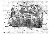
임의의 실시예들에서, 세포 배양 시스템(100)은 더 큰 조립체의 일부일 수도 있다. 도 6에 도시된 바와 같이, 세포 배양 조립체(150)는 여섯 개의 플레이트 웰들(10)이 구비된 여섯 개 들이 웰 플레이트(160)를 포함한다. 각각의 세포 배양 시스템(100)은 배양 배지 도관(70) 및 흡입 도관(60)을 포함하는데, 배양 배지 도관(70)은 플레이트 웰(10)의 경계에 인접하고, 흡입 도관(60)은 플레이트 웰(10)의 중심에 인접한다. 명확성을 위해서, 하나의 세포 배양 시스템(100)만이 도 6에서 식별되어 진다. 도시된 본 실시예에서, 각각의 배양 배지 도관(70)은 유연성 튜브(86)를 경유하여 벌크헤드(bulkhead)(85)에 결합된다. 다음으로, 벌크헤드(85)는 다수의 배지 공급 시스템(66)(도 4에 도시된)에 결합된다. 이러한 실시예에서, 유 량 또는 배지 유형과 같은 제어 파라미터들은 각각의 세포 배양 시스템에 대해서 개별적으로 제어될 수 있다.In certain embodiments,
또한, 각각의 흡입 도관(60)은 유연성 튜브(87)를 경유하여 공통 커넥터(88)에 함께 결합된다. 다음으로 공통 커넥터(88)는 진공 펌프(65)(도 4에 도시된)와 같은 저압 소스에 결합될 수도 있다. 다른 실시예들에서, 각각의 흡입 도관(60)은 개별적으로 결합될 수도 있어서 저압 소스들을 분리하고, 따라서 압력은 각각의 세포 배양 시스템(100)에 대해 개별적으로 제어될 수도 있다. 또한, 여섯 개 들이 웰 플레이트(160)에 뚜껑 조립체(75)를 견고하게 고정하는데 사용되는 패스너들(89)을 도 6에 도시된 실시예에서 볼 수 있다. 임의의 실시예들에서, 세포 배양 조립체(150)의 구성 요소들(뚜껑 조립체(75) 및 웰 플레이트(160)와 같은)은 빛이 투과할 수 있는 물질로 이루어진다. 이러한 실시예들에서, 세포 기질(40)은 평가를 목적으로 하는 세포 배양 과정 동안(예를 들어, 자극에 대한 형광 반응들을 포함하는) 관찰이 가능하다.In addition, each
임의의 실시예들에서, 세포 기질(40)은 배양 배지(71)가 통과해서 흐르기에 충분하고, 세포 증식 없이 TNP에 견디기에 충분히 강한 다공성 물질이다. 이러한 기질의 일 예는 구연산 나트륨(sodium citrate) 속의 돼지의 완전 혈액(whole blood)을 포함하는데, 회전시켜 혈장(plasma)으로부터 세포들을 분리하도록 한다. 이러한 실시예에서, 혈장은 피브리노겐(fibrinogen)에 대해서 분석 시험될 수도 있는데, 9.8 mg/mL에 해당하는 2 mL를 각각의 세포 배양 용기(20) 안에 담는다. 다음으로, 세포들을 세포 배양 용기(20) 당 약 20,000 세포씩 혈장 안으로 심고, 0.5 mL 트롬빈(thrombin)(배양 배지(71) 내 mL 당 1083단위)을 혈장/세포 혼합물에 점적식(drop-wise)으로 첨가할 수도 있다. 세포 기질(140)을 준비한 후, 배양 배지(71)를 세포 배양 용기(20)의 바닥면 및 세포 기질(140)의 상면에 첨가할 수 있다. 이러한 실시예에서, 세포들이 다른 실험에 앞서 약 2주 동안 증식하도록 할 수도 있다. 임의의 실시예들에서, 실험 직전에, 한천(agar) 1 mL(40 g/ L 농도의 트립틱 소이 아가(Tryptic Soy agar)와 같은)를 기질의 상면에 첨가할 수도 있다. 얇은 한천으로 이루어진 층은, 여전히 유체흐름을 허용할 정도의 충분한 다공성 상태 동안 TNP 하에서 세포 기질(140)을 안정화시키기 위해 사용될 수 있다.In certain embodiments, the
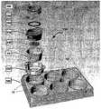
세포 배양 시스템(200)의 다른 실시예가 도 7 내지 도 22에 도시된다. 도 7의 분해도에서, 세포 배양 시스템(200)은 여섯 개 들이 웰 플레이트(160) 안에 플레이트 웰(10)을 포함한다. 도시된 본 실시예에서, 플레이트 웰(10)에는 주변 실링 부재(230), 세포 배양 용기(20), 드레싱(245), 인서트 실링 부재(254), 인서트 실 링(252), 횡단 실링 부재 또는 드레이프(250), 및 인서트 매니폴드(260)가 삽입된다. 이제 도 8의 조립 단면도를 참조하여, 본 실시예에서 주변 실링 부재(230)는 방사상 형상이고 플레이트 웰(10) 안으로 가압되고 세포 배양 용기(20)는 방사상 형상이고 주변 실링 부재(230)에 가압된다. 사용 중에, 세포 기질(240)은 투과성 막(22)의 상면에 배치된다. 다음으로 드레싱(245)은 세포 기질(240)의 상면 상에 배치될 수도 있고, 인서트 실링 부재(254)는 방사상으로 형성되어 세포 배양 용기(20) 안에 가압될 수 있다. 다음으로, 도시된 실시예에서, 드레이프(250)는 인서트 실 링(252) 상에 배치될 수 있고, 다음으로 인서트 실링 부재(254)의 립(lip)(253) 상에 배치된다. 인서트 매니폴드(260)는 인서트 실링 부재(254) 안으로 나사식으로 결합될 수 있다.Another embodiment of
이제 도 9의 상세 단면도를 참조하여, 주변 실링 부재(230)의 몸체(231)는 내부벽(11)에 밀착되어 플레이트 웰(10)과 주변 실링 부재(230) 사이에서 실제적으로 기밀이 유지되는 실(억지 끼움을 통해)을 형성한다. 이러한 실시예에서, 주변 실링 부재(230)가 플레이트 웰(10)에 직접적으로 접촉하는 반면에, 다른 실시예들은 주변 실링 부재(230)와 플레이트 웰(10) 사이에 추가적인 구성 요소들을 포함할 수도 있다. 이러한 실시예에서, 다수의 밀봉이 억지 끼움들을 통해서 형성되고, 다른 실시예들에서, 실제적인 기밀 상태는 오-링, 가스켓, 밀봉제 등과 같은 다른 메커니즘들을 통해서 형성될 수 있다. 추가적으로 실제적인 기밀 실들이 형성되는데, 주변 실링 부재(230)는 영역(232)에서 세포 배양 용기(20)에 밀착되고, 세포 배양 용기(20)는 영역(233)에서 인서트 실링 부재(254)에 접한다. 도시된 실시예에서, 드레이프(250)는 인서트 실 링(252) 상에 배치되는데, 인서트 실 링(252)은 인서트 실링 부재(254)의 립(253) 상에 배치된다. 이러한 실시예에서, 인서트 실 링(252)은 하나 이상의 구멍(255)을 포함하고, 드레이프(250)는 관통되어 구멍(255)과 정렬되는 여러 구멍들(미도시)을 가지는데, 그리하여 구멍들(255) 바로 위에 위치하는 공간이 구멍들(255) 아래에 위치하는 공간과 유체 연통하게 된다. 다음으로 인서트 매니폴드(260)는 인서트 실링 부재(254)에 나사식으로 결합될 수 있는데, 이로써 드레이프(250)를 인서트 실 링(252)에 대해서 견고하게 고정하고 인서트 실 링(252)을 립(253)에 대해서 견고하게 고정하게 된다.Referring now to the detailed cross-sectional view of FIG. 9, the
도 8 및 도 9에 도시된 바와 같이, 도관(270)은 주변 실링 부재(230)를 통과해서 연장되는데, 배양 배지(271)가 투과성 막(22)을 통해서 세포 기질(240)에 도달하기 위한 경로를 제공한다(앞선 실시예에서 설명된 방식과 유사한). 이러한 실시예에서 또한 도시된 바와 같이, 인서트 매니폴드(260)는 인서트 실 링(252)의 구멍들(255) 및 드레이프(250)에 제공되는 임의의 구멍들과 유체 연통하는 도관(262)을 포함한다. 따라서, 저압 소스(도 4에 도시된 저압 소스(65)와 같은)는 도관(262)과 결합하고 저압 또는 흡입력을 드레싱(245)에 제공하여 앞서 언급한 실시예와 유사한 방식으로 세포 기질(240)의 역학적 전이 및 마이크로 변형을 야기한다.As shown in FIGS. 8 and 9, the
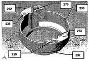
조립된 세포 배양 시스템(200)의 평면도가 도 10에 도시된다. 본 실시예에서 플레이트 웰(10)로부터 연장되게 도시된 바와 같이, 주변 실링 부재(230)는 탭들(232), (234)을 포함하고, 세포 배양 용기(20)는 플랜지들(24)을 포함하며, 인서트 실링 부재(254)는 탭들(256)을 포함한다. 본 실시예에서, 탭들(232), (234), (256)은 포트(port)가 열려 있는 지를 알려주는 표식(아래에 더 상세히 설명될)뿐만 아니라 구성 요소들의 정렬에 관한 표식을 포함한다.A top view of the assembled
이제 도 11 내지 도 13을 참조하여, 주변 실링 부재(230)의 보다 상세한 특징들을 볼 수 있다. 본 실시예에서, 주변 실링 부재(230)는 몸체(231)를 포함하는데, 몸체(231)는 실제적으로 실린더 형상이고, 한 쌍의 노치(236), 탭들(232), (234), 도관(270), 및 실링된 도관(273)을 구비한다. 노치들(236)은 세포 배양 용기(20)로부터 연장되는 탭(26)(도 2에 도시된)과 정렬되도록 구성된다. 실링 도 관(273)은 격막(272)을 포함하는데, 격막(272)은 실링 도관(273)을 열어 놓는 것이 바람직할 경우 관통될 수 있고, 그래서 배양 배지(271)를 위한 제2경로 또는 압력 감지 포트 용도로 사용될 수도 있다. 탭(232) 상의 범프(235)는 탭(232)으로부터 연장되는 도관(270)이 실링되어 있지 않고 열려 있음을 나타내고, 표식(229)은 조립과정 동안의 정렬을 위한 가이드 역할을 한다. 탭들(232), (234)의 반대에 있는 몸체(231)의 단부에는 테이퍼진 테이퍼 부(239)가 배치되는데, 테이퍼 부(239)는 채널들(237)을 구비한 칼라(collar)(238)로 연장된다. 앞서 언급한 실시예의 채널들(37)과 유사하게, 채널들(237)은 배양 배지(271)가 도관(270)으로부터 투과성 막(22) 및 세포 기질(240)로 흘러가기 위한 경로를 제공하고, 이로써 세포 기질(240)을 위한 영양분들을 제공한다.Referring now to FIGS. 11-13, more detailed features of the peripheral sealing
이제 도 14 내지 도 16을 참조하여, 인서트 실링 부재(254)의 더 상세한 특징들을 볼 수 있다. 본 실시예에서, 인서트 실링 부재(254)는 몸체(251)를 포함하는데, 몸체(251)는 실제적으로 실린더 형상이고 내부에 나사산부(259)를 가진다. 본 실시예에서, 탭들(256)은 몸체(251)의 일 단에서 외측으로 연장되는 한편, 립(253)은 몸체(251)의 반대 단에서부터 내측으로 연장된다. 탭들(256)은 정렬 표식(258) 및 한 쌍의 릴리프(257)를 또한 포함하여 세포 배양 용기(20)의 날카로운 모서리(300)(도 2)에 대한 여유 공간(clearance)를 제공한다.Referring now to FIGS. 14-16, more detailed features of the
이제 도 17 내지 도 18을 참조하여, 인서트 실 링(252)의 보다 상세한 특징들을 볼 수 있다. 본 실시예에서, 인서트 실 링(252)은 복수개의 구멍들(255)을 포함한다. 또한, 인서트 실 링(252)의 본 실시예는 융기부(242)를 포함해서 단면이 도 18에 도시된 바와 같이 대략 ‘V’ 형상을 하게 된다.Referring now to FIGS. 17-18, more detailed features of the
이제 도 19 내지 도 21을 참조하여, 인서트 매니폴드(260)의 보다 상세한 특징들을 볼 수 있다. 본 실시예에서, 인서트 매니폴드(260)는 외측으로 형성된 나사산부(269)를 구비한 일반적으로 실린더형 몸체(261)를 포함한다. 본 실시예는 또한 실링된 실링 도관(264)을 포함하는데, 실링 도관(264)은 실링 도관(264)을 열어 놓는 것이 바람직할 경우 관통될 수 있는 격막(268)을 포함한다. 열려 있는 경우, 실링 도관(264)은 추가적인 저압 도관용으로 또는 압력 감지 포트로 사용될 수도 있다. 본 실시예에서, 인서트 매니폴드(260)는 돌기부(263)를 포함하는데, 돌기부(263)는 실링된 상태가 아닌 열려 상태를 나타낸다. 도 20 및 도 21에는 채널(267)(열려 있을 경우 실링 도관(264) 및 도관(262)과 유체 연통하는) 및 둥글게 처리된 라운딩(rounding) 모서리들(265), (266)이 도시된다. 도 9에 도시된 바와 같이, 라운딩 모서리들(265), (266)은 채널(267)이 인서트 실 링(252)의 구멍들(255)과 유체 연통하도록 인서트 실 링(252)에 밀착될 수도 있다.Referring now to FIGS. 19-21, more detailed features of the
이제 도 22를 참조하여, 인서트 매니폴드(260), 드레이프(250), 인서트 실 링(252), 및 인서트 실링 부재(254)가 분해도에서 내부 인서트 조립체(275)의 일 실시예로서 도시된다. 다른 실시예들에서 내부 인서트 조립체(275)의 임의의 별도 구성 요소들이 조합될 수도 있는 것으로 이해된다. 예를 들어, 인서트 실 링(252)은 인서트 실링 부재(254) 또는 인서트 매니폴드(260)에 통합될 수도 있다. 사용중에, 내부 인서트 조립체(275)는 세포 배양 용기(20)의 내부 경계(29)에 걸쳐서 실을 제공하도록 구성된다. 도 22에 도시된 실시예의 조립 중에, 드레이프(250)는 인 서트 실 링(252) 위에 배치되고, 초과분의 물질은 인서트 실 링(252)의 경계 주위에 있는 드레이프(250)에서 제거된다. 다음으로 홀들이 드레이프(250)에 생성될 수도 있는데, 인서트 실 링(252)의 구멍들(255)과 정렬된다. 다음으로, 도시된 실시예에서, 인서트 매니폴드(260)는 인서트 실링 부재(254)에 나사식으로 삽입될 수도 있는데, 이로 인해 도 9에 도시된 바와 같이 라운딩된 모서리들(275), (266)을 드레이프(250)에 밀착시키고 인서트 실 링(252)에 대해 이를 압축하여 실질적으로 인서트 실링 부재(254)의 립(253)과의 실질적인 기밀(air tight seal)을 형성한다. 또한, 인서트 실링 부재(254)의 몸체(251)는 세포 배양 용기(20)의 내부 경계(29)에 밀착되고, 이로써 내부 경계(29)에 걸쳐서 실제적으로 기밀을 유지하는 실을 형성하게 된다. 따라서, 도 9의 실시예에서 도시된 바와 같이, 내부 인서트 조립체(275)는 주변 실링 부재(230)와 조합되어 실링 시스템을 형성할 수도 있는데, 실링 시스템은 세포 배양 용기(20)의 외부벽(19) 및 내부 경계(29)와의 실제적인 기밀 실들을 제공한다. 도시된 실시예에서, 주변 실링 부재(230)의 테이퍼 부(239)는 외부벽(19)과 억지 끼움으로 밀착되고, 몸체(251)(립(253)의 경계면과 인접한)는 세포 배양 용기(20)의 내부 경계(29)와 밀착된다. 따라서, 세포 배양 용기(20)는 외부와 내부 양 측에서 효과적으로 실링되며, 세포 배양 용기(20) 내에 포함된 세포 기질에 유효 TNP가 가해지도록 한다. 또한, 세포 배양 시스템(200)은 도 6에 도시된 세포 배양 시스템(100)과 유사한 방식으로 추가적인 세포 배양 시스템들과 조합될 수도 있다.Referring now to FIG. 22,
다른 실시예들에서, 세포 배양 용기는 세포들을 배양하기에 적합한 임의의 장치일 수도 있고 세포 배양 인서트와는 다른 장치일 수도 있다. 도 23 및 도 24를 참조하여, 세포 배양 용기(410)를 포함하는 세포 배양 시스템(400)의 다른 실시예가 도시되는데, 세포 배양 용기(410)는 주변벽들(419) 및 바닥부(420)를 포함한다. 본 실시예에서, 세포 배양 용기(410)는 투과성 지지부(422)와 드레싱(445) 사이에서 세포 배양 기질(440)를 포함한다. 도시된 실시예에서, 뚜껑(450)은 드레싱(445)을 덮고, 흡입 도관(460)(저압 소스와 결합, 미도시)은 드레싱(445) 및 세포 배양 기질(440)에 음압을 제공할 수도 있다. 본 실시예에서, 배양 배지 도관(470)은 세포 배양 용기(410)에 결합되어 배양 배지(471)를 제공하는데, 투과성 지지부(422)를 통해서 세포 배양 기질(440)로 흐를 수 있다.In other embodiments, the cell culture vessel may be any device suitable for culturing cells or may be a device other than a cell culture insert. Referring to FIGS. 23 and 24, another embodiment of a
사용 중에, 본 실시예는 앞서 언급한 실시예들과 동등한 방식으로 가동되고, 흡입 도관(460)은 세포 기질(440)의 제1표면(441)(여기서는 상면으로 도시된)에 음압을 가한다. 또한, 배양 배지 도관(470)은 배양 배지(470)를 세포 배양 기질(440)의 제2표면(442)(여기서는 하면으로 도시된)에 제공한다. 도시된 바와 같이, 주변벽들(419), 바닥부(420), 및 뚜껑(450)은 실제적으로 기밀을 유지하는 인클로져(421)를 제공하는데, 인클로져(421)는 세포 배양 기질(440)를 효과적으로 실링한다(흡입 도관(460) 및 배양 배지 도관(470)을 제외하고). 본 실시예에서, 흡입 도관(460)은 뚜껑(450)을 통과해서 연장되고 세포 배양 기질(440)에 가해지는 음압의 양을 제어하기 위해 사용될 수 있다(저압 소스와 결합하는 경우에). 유사하게, 배양 배지 도관(470)은 주변벽들(419)을 통과해서 연장되고 세포 배양 기질(440)에 제공되는 배양 배지(471)의 양을 제어하기 위해 사용될 수 있다.In use, this embodiment operates in an equivalent manner to the aforementioned embodiments, and the
도시된 실시예에서, 세포 배양 용기(410)는 세포 배양 용기(410)와 더 큰 조립체(웰 플레이트와 같은) 사이에서 별도의 주변 실링 부재를 요구하지 않는데, 왜냐하면 세포 배양 배지 도관(470)은 세포 배양 용기(410)의 주변벽들(419)을 관통해서 연장되기 때문이다. 세포 배양 시스템(400)은 단일 세포 배양 용기(410) 또는 다수개의 세포 배양 용기들(410)을 구비하여 작동할 수도 있다. 도시된 실시예에서, 투과성 지지부(422)는 다수의 다른 구성들 중 어느 하나를 포함할 수도 있다. 예를 들어, 투과성 지지부(422)는 메시(mesh) 물질, 구멍이 있는 배리어(barrier), 또는 막을 포함할 수도 있다. 이러한 실시예에서, 뚜껑(450)은 앞서 설명한 실시예들의 것들과 유사한 유연성 드레이프일 수도 있고, 또는 뚜껑(450)은 주변벽들(419)에 실링 방식으로 밀착하는 더 단단한 부재일 수도 있다. 본 개시된 실시예는 예시적인 목적으로만 제공되고, 본 발명의 범위 내에서 개시된 실시예의 다양한 수정 및 변형이 존재한다.In the illustrated embodiment,
본 명세서 전체를 통해서, 두 개의 구성 요소들 “사이를 실링”한다는 언급은 두 개의 구성 요소들이 서로 접촉하는 것을 요구하지는 않는다. 추가적인 구성 요소들이 두 개 이상의 구성 요소들 사이에서 위치할 수도 있고, 이들 사이에 실을 가진다. 본 명세서 안에서 언급하는 “저(low)”, “감소된”, “음(negative)”, 또는 “흡입” 압(pressure)은 대기압보다 작은 임의의 압력을 의미한다.Throughout this specification, reference to “seal between” two components does not require the two components to contact each other. Additional components may be located between two or more components, with a seal between them. As used herein, "low", "reduced", "negative", or "suction" pressure means any pressure less than atmospheric pressure.
임의의 실시예들에서, 주변 실링 부재(230), 인서트 실링 부재(254), 및 인서트 매니폴드(260)(및 다른 구성 요소들)은 사출 성형에 의해 제조될 수도 있다. 다른 실시예들은 캐스팅(casting) 부품들, 여러 비규격의 오-링 사이즈, 또는 대체 물질들을 포함할 수도 있다. 임의의 실시예들에서, 인서트(20) 및 플레이트 웰(10)(다른 구성 요소들도 물론)은 즉시 이용 가능한(또는 기성품) 아이템들인 표준 구성 요소들일 수도 있다. 이러한 표준 부품들의 사용은 소독량을 최소화할 수 있는데, 이러한 구성 요소들은 일회용 또는 소모성 구성 요소들로 취급될 수도 있기 때문이다.In some embodiments, peripheral sealing
임의의 실시예들에서, 배지의 흐름은 폐루프 피드백 시스템(closed-loop feedback system)을 이용하여 자동적으로 제어될 수도 있는데, 폐루프 피드백 시스템은 압력, 흐름, 또는 다른 파라미터 센서들을 포함하고, 배지 흐름은 경사, 역전, 순환, 또는 재순환될 수도 있다. 임의의 실시예들에서, 플레이트 웰들은 병렬 또는 직렬로 결합될 수도 있고, 기체 분사 또는 온도 제어 장치가 추가될 수도 있다. 임의의 실시예들에서, 여러 광학적 센서들 또는 여러 화상 장치들 뿐만 아니라 다양한 LED 또는 다른 마이크로 전자 기기를 시스템에 포함시킴으로써 광학적 방사(UV 또는 IR)를 추가시킬 수도 있다. 플레이트 웰들 둘레 또는 안에 전자기, 정전기, 및 자기장 생성기들을 포함시킴으로써 이러한 전자기, 정전기, 및 자기장들이 유도될 수도 있다. 임의의 실시예들은 MEMS, 또는 마이크로 유체기술 장치(microfluidics)와 같은 기계적 인장 유도 장치들을 포함할 수도 있고, 시스템은 선충류(nematodes), 기생충류(parasites), 미생물류(microbes), 또는 작은 곤충들의 연구를 위해 사용될 수도 있다.In some embodiments, the flow of the medium may be automatically controlled using a closed-loop feedback system, where the closed loop feedback system includes pressure, flow, or other parameter sensors, and the medium The flow may be inclined, reversed, circulated, or recycled. In some embodiments, plate wells may be combined in parallel or in series, and a gas injection or temperature control device may be added. In certain embodiments, optical radiation (UV or IR) may be added by including various optical sensors or various imaging devices as well as various LEDs or other microelectronics in the system. Such electromagnetic, electrostatic, and magnetic fields may be induced by including electromagnetic, electrostatic, and magnetic field generators in or around the plate wells. Certain embodiments may include mechanical tension inducing devices, such as MEMS, or microfluidics, wherein the system may be made of nematodes, parasites, microbes, or small insects. It can also be used for research.
임의의 실시예들에서, 불균일한 모양을 가지는 조직 샘플들은 왁스 캐스팅(was casting) 또는 유사한 수단들에 의해 인서트에 실링될 수 있다. 임의의 실 시예들에서, 배양물을 통한 흐름 속도 및 방향을 제어하기 위해 배양물의 정점 표면은 부분적으로 메워진 덮개를 가질 수도 있고, 막(22)의 일부가 메워질 수도 있다. 예를 들어, 막(22)의 외부 가장자리를 제외한 모든 곳을 메우고 정점 덮개 내의 중심 구멍을 제외한 모든 곳을 메움으로써 방사상류(radial flow)를 유도할 수 있다.In some embodiments, tissue samples having a non-uniform shape may be sealed to the insert by was casting or similar means. In some embodiments, the apex surface of the culture may have a partially filled lid and part of the
임의의 실시예들에서, 세포 기질(140)은 혈장 대신에 트롬빈 및 소 피브리노겐(bovine fibrinogen)을 포함할 수도 있다. 또한 세포 기질(140)이 무너지지 않고 TNP에 견딘다는 조건으로, 실시예들은 퓨라매트릭스(Puramatrix ™), 키토산(chitosan), 전분(starch) 또는 콜라겐(collagen)과 같은 세포 외 기질 구성 요소들 및 또는 다양한 다른 생체 적합성 폴리머들을 포함할 수도 있다. 다른 실시예들에서, 세포 기질(140)은 상아질(dentin) 또는 뼈와 같은 조직의 얇은 조각들 또는 부분층 피부 이식 조각들(split thickness skin grafts)과 같은 조직 샘플들, 이식형 믹스들(implantable mixes), 재흡수 가능한 물질들(resorbable materials)을 포함할 수도 있다.In certain embodiments, cell substrate 140 may include thrombin and bovine fibrinogen instead of plasma. Also provided that the cell substrate 140 is resistant to TNP without breaking down, embodiments include extracellular matrix components such as Puramatrix ™, chitosan, starch or collagen, and / or Various other biocompatible polymers may be included. In other embodiments, the cell substrate 140 may be implantable with tissue samples, such as thin slices of skin such as dentin or bone, or split thickness skin grafts. mixes, resorbable materials.
본 발명이 상기와 같이 상세히 도시되고 설명되었지만, 여러 수정 및 변경들이 본 발명의 범위 안에서 이루어질 수도 있음은 해당 기술 분야의 당업자에게는 분명하다. 이와 같이, 앞서의 설명 및 첨부 도면들에서 진술되는 바는, 다만 예시적인 방식으로 제공되는 것이지 한정하기 위한 것은 아니다. 본 발명의 실제적인 범위를 다음의 청구항들을 통해 정의하고자 하며, 이러한 청구항들의 권리에 속하는 동등물들의 전체 영역도 함께 포함된다.While the invention has been shown and described in detail above, it is apparent to those skilled in the art that various modifications and changes may be made within the scope of the invention. As such, what is stated in the foregoing description and the accompanying drawings is provided by way of example only, and not limitation. It is intended that the actual scope of the invention be defined by the following claims, along with the full scope of equivalents falling within the scope of these claims.
또한, 해당 기술 분야의 당업자는 본 명세서에서 설명된 발명에 대한 다른 변형이 본 발명의 범위 안에 포함될 수 있다는 것을 읽고 이해하면서 인식하게 될 것이다. 예를 들어, 임의의 실시예들에서, 주변 실링 부재들(30), (230)은 하나의 구성 요소일 수도 있다. 다른 실시예들에서, 주변 실링 부재들(30), (230)은 다수의 구성 요소들일 수도 있다.In addition, those skilled in the art will recognize and appreciate that other modifications to the invention described herein may be included within the scope of the invention. For example, in some embodiments, peripheral sealing
앞선 개시된 실시예들의 상세 설명에서, 다양한 특징들은 본 명세서를 간소화할 목적으로 몇몇 실시예들로 분류하였다. 본 명세서의 이러한 방법은, 본 발명의 실시예들이 각 청구항에서 명확히 상술되는 것보다 더 많은 특징들을 요구하고자 하는 의도를 반영하는 것으로 해석되지 않는다. 오히려, 다음의 청구항들이 반영하는 바와 같이, 발명의 주제는 하나의 개시된 실시예의 모든 특징들 이내에 존재한다. 따라서, 다음의 청구항들은 이에 개시된 실시예들의 상세한 설명에 통합되는데, 각각의 청구항은 독립적으로 별도의 실시예로서 존재한다.In the foregoing detailed description of embodiments, various features have been grouped into several embodiments for the purpose of streamlining the disclosure. This method of the present specification is not to be interpreted as reflecting the intention of the embodiments of the invention to require more features than are specifically described in each claim. Rather, as the following claims reflect, inventive subject matter lies within all features of one disclosed embodiment. Accordingly, the following claims are incorporated into the detailed description of the embodiments disclosed herein, with each claim standing on its own as a separate embodiment.
Claims (36)
Translated fromKoreanApplications Claiming Priority (5)
| Application Number | Priority Date | Filing Date | Title |
|---|---|---|---|
| US75972306P | 2006-01-18 | 2006-01-18 | |
| US60/759,723 | 2006-01-18 | ||
| US11/624,017 | 2007-01-17 | ||
| US11/624,017US7981668B2 (en) | 2006-01-18 | 2007-01-17 | System and method for applying reduced pressure to cell culture |
| PCT/US2007/001460WO2007084677A2 (en) | 2006-01-18 | 2007-01-18 | System and method for applying reduced pressure to cell culture |
Publications (2)
| Publication Number | Publication Date |
|---|---|
| KR20080088637Atrue KR20080088637A (en) | 2008-10-02 |
| KR101105534B1 KR101105534B1 (en) | 2012-01-13 |
Family
ID=38263674
Family Applications (1)
| Application Number | Title | Priority Date | Filing Date |
|---|---|---|---|
| KR1020087020110AExpired - Fee RelatedKR101105534B1 (en) | 2006-01-18 | 2007-01-18 | System and method for applying reduced pressure to cell culture |
Country Status (10)
| Country | Link |
|---|---|
| US (1) | US7981668B2 (en) |
| EP (1) | EP1974008B1 (en) |
| JP (1) | JP5204667B2 (en) |
| KR (1) | KR101105534B1 (en) |
| AU (1) | AU2007207472B2 (en) |
| BR (1) | BRPI0706850A2 (en) |
| CA (1) | CA2633984C (en) |
| IL (1) | IL192699A0 (en) |
| RU (1) | RU2447142C2 (en) |
| WO (1) | WO2007084677A2 (en) |
Cited By (1)
| Publication number | Priority date | Publication date | Assignee | Title |
|---|---|---|---|---|
| KR20200078296A (en)* | 2018-12-21 | 2020-07-01 | 가톨릭대학교 산학협력단 | Microfluidic chip for promoting airway differentiation by controlling air flow |
Families Citing this family (19)
| Publication number | Priority date | Publication date | Assignee | Title |
|---|---|---|---|---|
| US11298453B2 (en) | 2003-10-28 | 2022-04-12 | Smith & Nephew Plc | Apparatus and method for wound cleansing with actives |
| US8758313B2 (en) | 2003-10-28 | 2014-06-24 | Smith & Nephew Plc | Apparatus and method for wound cleansing with actives |
| DE102007030413A1 (en)* | 2007-06-29 | 2009-01-02 | Fraunhofer-Gesellschaft zur Förderung der angewandten Forschung e.V. | Method for investigating the effect of a gaseous medium on a biological test system using an extracellular metabolization system and device for carrying out the method |
| US20090234306A1 (en) | 2008-03-13 | 2009-09-17 | Tyco Healthcare Group Lp | Vacuum wound therapy wound dressing with variable performance zones |
| JP5909348B2 (en)* | 2011-12-05 | 2016-04-26 | 株式会社日立製作所 | Cultivation container, automatic culture apparatus, and medium supply method |
| US10323221B2 (en)* | 2016-01-06 | 2019-06-18 | Northeastern University | Device for controlled apical flow in cell culture inserts |
| EP3500355B1 (en) | 2016-08-21 | 2024-04-10 | ADVA Biotechnology Ltd. | Bioreactor and methods of use thereof |
| JP6968381B2 (en)* | 2016-09-09 | 2021-11-17 | 国立大学法人 東京大学 | Cell culture device |
| WO2020001733A1 (en)* | 2018-06-25 | 2020-01-02 | Universitätsklnikum Hamburg-Eppendorf | A holding device for microscopy applications and microscopy chamber |
| US20210371786A1 (en)* | 2018-10-03 | 2021-12-02 | Oregon Health & Science University | Microfluidic devices for dental applications |
| CN113710792A (en)* | 2019-05-08 | 2021-11-26 | 株式会社岛津制作所 | Cell evaluation device |
| US11767497B2 (en) | 2019-07-28 | 2023-09-26 | Propria LLC | System and method for generating and testing tissue |
| KR20220130743A (en) | 2020-01-20 | 2022-09-27 | 아드바 바이오테크놀로지 리미티드 | Apparatus and method for controlling a bioreactor |
| US20220154120A1 (en)* | 2020-11-16 | 2022-05-19 | Northeastern University | Hanging Cell Culture Millifluidic Device |
| WO2022112364A2 (en)* | 2020-11-24 | 2022-06-02 | Helmholtz Zentrum Muenchen - Deutsches Forschungszentrum Für Gesundheit Und Umwelt (Gmbh) | Biocompatible composite membrane, method for fabricating the membrane, bioreactor and method for investigating cells attached to the biocompatible composite membrane |
| US12359155B2 (en)* | 2021-04-23 | 2025-07-15 | The Charles Stark Draper Laboratory Inc. | Highly deformable porous membrane culture system and actuation methods for studying the effects of biomechanical stretch on cultured tissue |
| GB2624872B (en)* | 2022-11-29 | 2024-11-20 | 3Brain Ag | Improvements in or relating to cellular assays |
| WO2024238592A2 (en)* | 2023-05-15 | 2024-11-21 | Emory University | Systems and devices for high throughput cell and vector co-localizations |
| US12312573B1 (en)* | 2024-10-17 | 2025-05-27 | Amnio Technology Llc | Tissue culture plate material retainer system |
Family Cites Families (129)
| Publication number | Priority date | Publication date | Assignee | Title |
|---|---|---|---|---|
| US1355846A (en) | 1920-02-06 | 1920-10-19 | David A Rannells | Medical appliance |
| US2547758A (en) | 1949-01-05 | 1951-04-03 | Wilmer B Keeling | Instrument for treating the male urethra |
| US2632443A (en) | 1949-04-18 | 1953-03-24 | Eleanor P Lesher | Surgical dressing |
| GB692578A (en) | 1949-09-13 | 1953-06-10 | Minnesota Mining & Mfg | Improvements in or relating to drape sheets for surgical use |
| US2682873A (en) | 1952-07-30 | 1954-07-06 | Johnson & Johnson | General purpose protective dressing |
| NL189176B (en) | 1956-07-13 | 1900-01-01 | Hisamitsu Pharmaceutical Co | PLASTER BASED ON A SYNTHETIC RUBBER. |
| US2969057A (en) | 1957-11-04 | 1961-01-24 | Brady Co W H | Nematodic swab |
| US3066672A (en) | 1960-09-27 | 1962-12-04 | Jr William H Crosby | Method and apparatus for serial sampling of intestinal juice |
| US3367332A (en) | 1965-08-27 | 1968-02-06 | Gen Electric | Product and process for establishing a sterile area of skin |
| US3520300A (en) | 1967-03-15 | 1970-07-14 | Amp Inc | Surgical sponge and suction device |
| US3568675A (en) | 1968-08-30 | 1971-03-09 | Clyde B Harvey | Fistula and penetrating wound dressing |
| US3682180A (en) | 1970-06-08 | 1972-08-08 | Coilform Co Inc | Drain clip for surgical drain |
| BE789293Q (en) | 1970-12-07 | 1973-01-15 | Parke Davis & Co | MEDICO-SURGICAL DRESSING FOR BURNS AND SIMILAR LESIONS |
| US3826254A (en) | 1973-02-26 | 1974-07-30 | Verco Ind | Needle or catheter retaining appliance |
| DE2527706A1 (en) | 1975-06-21 | 1976-12-30 | Hanfried Dr Med Weigand | DEVICE FOR THE INTRODUCTION OF CONTRAST AGENTS INTO AN ARTIFICIAL INTESTINAL OUTLET |
| DE2640413C3 (en) | 1976-09-08 | 1980-03-27 | Richard Wolf Gmbh, 7134 Knittlingen | Catheter monitor |
| NL7710909A (en) | 1976-10-08 | 1978-04-11 | Smith & Nephew | COMPOSITE STRAPS. |
| GB1562244A (en) | 1976-11-11 | 1980-03-05 | Lock P M | Wound dressing materials |
| US4080970A (en) | 1976-11-17 | 1978-03-28 | Miller Thomas J | Post-operative combination dressing and internal drain tube with external shield and tube connector |
| US4139004A (en) | 1977-02-17 | 1979-02-13 | Gonzalez Jr Harry | Bandage apparatus for treating burns |
| US4184510A (en) | 1977-03-15 | 1980-01-22 | Fibra-Sonics, Inc. | Valued device for controlling vacuum in surgery |
| US4165748A (en) | 1977-11-07 | 1979-08-28 | Johnson Melissa C | Catheter tube holder |
| US4245637A (en) | 1978-07-10 | 1981-01-20 | Nichols Robert L | Shutoff valve sleeve |
| SE414994B (en) | 1978-11-28 | 1980-09-01 | Landstingens Inkopscentral | VENKATETERFORBAND |
| GB2047543B (en) | 1978-12-06 | 1983-04-20 | Svedman Paul | Device for treating tissues for example skin |
| US4284079A (en) | 1979-06-28 | 1981-08-18 | Adair Edwin Lloyd | Method for applying a male incontinence device |
| US4261363A (en) | 1979-11-09 | 1981-04-14 | C. R. Bard, Inc. | Retention clips for body fluid drains |
| US4569348A (en) | 1980-02-22 | 1986-02-11 | Velcro Usa Inc. | Catheter tube holder strap |
| WO1981002516A1 (en) | 1980-03-11 | 1981-09-17 | E Schmid | Cushion for holding an element of grafted skin |
| US4297995A (en) | 1980-06-03 | 1981-11-03 | Key Pharmaceuticals, Inc. | Bandage containing attachment post |
| US4333468A (en) | 1980-08-18 | 1982-06-08 | Geist Robert W | Mesentery tube holder apparatus |
| US4465485A (en) | 1981-03-06 | 1984-08-14 | Becton, Dickinson And Company | Suction canister with unitary shut-off valve and filter features |
| US4392853A (en) | 1981-03-16 | 1983-07-12 | Rudolph Muto | Sterile assembly for protecting and fastening an indwelling device |
| US4373519A (en) | 1981-06-26 | 1983-02-15 | Minnesota Mining And Manufacturing Company | Composite wound dressing |
| US4392858A (en) | 1981-07-16 | 1983-07-12 | Sherwood Medical Company | Wound drainage device |
| US4419097A (en) | 1981-07-31 | 1983-12-06 | Rexar Industries, Inc. | Attachment for catheter tube |
| SE429197B (en) | 1981-10-14 | 1983-08-22 | Frese Nielsen | SAR TREATMENT DEVICE |
| DE3146266A1 (en) | 1981-11-21 | 1983-06-01 | B. Braun Melsungen Ag, 3508 Melsungen | COMBINED DEVICE FOR A MEDICAL SUCTION DRAINAGE |
| US4551139A (en) | 1982-02-08 | 1985-11-05 | Marion Laboratories, Inc. | Method and apparatus for burn wound treatment |
| US4475909A (en) | 1982-05-06 | 1984-10-09 | Eisenberg Melvin I | Male urinary device and method for applying the device |
| EP0100148B1 (en) | 1982-07-06 | 1986-01-08 | Dow Corning Limited | Medical-surgical dressing and a process for the production thereof |
| NZ206837A (en) | 1983-01-27 | 1986-08-08 | Johnson & Johnson Prod Inc | Thin film adhesive dressing:backing material in three sections |
| US4548202A (en) | 1983-06-20 | 1985-10-22 | Ethicon, Inc. | Mesh tissue fasteners |
| US4540412A (en) | 1983-07-14 | 1985-09-10 | The Kendall Company | Device for moist heat therapy |
| US4543100A (en) | 1983-11-01 | 1985-09-24 | Brodsky Stuart A | Catheter and drain tube retainer |
| US4525374A (en) | 1984-02-27 | 1985-06-25 | Manresa, Inc. | Treating hydrophobic filters to render them hydrophilic |
| CA1286177C (en) | 1984-05-03 | 1991-07-16 | Smith And Nephew Associated Companies Plc | Adhesive wound dressing |
| US4897081A (en) | 1984-05-25 | 1990-01-30 | Thermedics Inc. | Percutaneous access device |
| US5215522A (en) | 1984-07-23 | 1993-06-01 | Ballard Medical Products | Single use medical aspirating device and method |
| GB8419745D0 (en) | 1984-08-02 | 1984-09-05 | Smith & Nephew Ass | Wound dressing |
| US4872450A (en) | 1984-08-17 | 1989-10-10 | Austad Eric D | Wound dressing and method of forming same |
| US4655754A (en) | 1984-11-09 | 1987-04-07 | Stryker Corporation | Vacuum wound drainage system and lipids baffle therefor |
| US4826494A (en) | 1984-11-09 | 1989-05-02 | Stryker Corporation | Vacuum wound drainage system |
| US4605399A (en) | 1984-12-04 | 1986-08-12 | Complex, Inc. | Transdermal infusion device |
| US5037397A (en) | 1985-05-03 | 1991-08-06 | Medical Distributors, Inc. | Universal clamp |
| US4640688A (en) | 1985-08-23 | 1987-02-03 | Mentor Corporation | Urine collection catheter |
| US4710165A (en) | 1985-09-16 | 1987-12-01 | Mcneil Charles B | Wearable, variable rate suction/collection device |
| US4758220A (en) | 1985-09-26 | 1988-07-19 | Alcon Laboratories, Inc. | Surgical cassette proximity sensing and latching apparatus |
| US4733659A (en) | 1986-01-17 | 1988-03-29 | Seton Company | Foam bandage |
| US4838883A (en) | 1986-03-07 | 1989-06-13 | Nissho Corporation | Urine-collecting device |
| JPS62281965A (en) | 1986-05-29 | 1987-12-07 | テルモ株式会社 | Catheter and catheter fixing member |
| GB8621884D0 (en) | 1986-09-11 | 1986-10-15 | Bard Ltd | Catheter applicator |
| GB2195255B (en) | 1986-09-30 | 1991-05-01 | Vacutec Uk Limited | Apparatus for vacuum treatment of an epidermal surface |
| US4743232A (en) | 1986-10-06 | 1988-05-10 | The Clinipad Corporation | Package assembly for plastic film bandage |
| DE3634569A1 (en) | 1986-10-10 | 1988-04-21 | Sachse Hans E | CONDOM CATHETER, A URINE TUBE CATHETER FOR PREVENTING RISING INFECTIONS |
| JPS63135179A (en) | 1986-11-26 | 1988-06-07 | 立花 俊郎 | Subcataneous drug administration set |
| GB8628564D0 (en) | 1986-11-28 | 1987-01-07 | Smiths Industries Plc | Anti-foaming agent suction apparatus |
| GB8706116D0 (en) | 1987-03-14 | 1987-04-15 | Smith & Nephew Ass | Adhesive dressings |
| US4787888A (en) | 1987-06-01 | 1988-11-29 | University Of Connecticut | Disposable piezoelectric polymer bandage for percutaneous delivery of drugs and method for such percutaneous delivery (a) |
| US4863449A (en) | 1987-07-06 | 1989-09-05 | Hollister Incorporated | Adhesive-lined elastic condom cathether |
| US5176663A (en) | 1987-12-02 | 1993-01-05 | Pal Svedman | Dressing having pad with compressibility limiting elements |
| US4906240A (en) | 1988-02-01 | 1990-03-06 | Matrix Medica, Inc. | Adhesive-faced porous absorbent sheet and method of making same |
| US4985019A (en) | 1988-03-11 | 1991-01-15 | Michelson Gary K | X-ray marker |
| GB8812803D0 (en) | 1988-05-28 | 1988-06-29 | Smiths Industries Plc | Medico-surgical containers |
| US4919654A (en) | 1988-08-03 | 1990-04-24 | Kalt Medical Corporation | IV clamp with membrane |
| US5000741A (en) | 1988-08-22 | 1991-03-19 | Kalt Medical Corporation | Transparent tracheostomy tube dressing |
| US5059596A (en) | 1989-01-16 | 1991-10-22 | Roussel Uclaf | Azabicyclo compounds |
| US5100396A (en) | 1989-04-03 | 1992-03-31 | Zamierowski David S | Fluidic connection system and method |
| US4969880A (en) | 1989-04-03 | 1990-11-13 | Zamierowski David S | Wound dressing and treatment method |
| US5527293A (en) | 1989-04-03 | 1996-06-18 | Kinetic Concepts, Inc. | Fastening system and method |
| US5261893A (en) | 1989-04-03 | 1993-11-16 | Zamierowski David S | Fastening system and method |
| JP2719671B2 (en) | 1989-07-11 | 1998-02-25 | 日本ゼオン株式会社 | Wound dressing |
| US5358494A (en) | 1989-07-11 | 1994-10-25 | Svedman Paul | Irrigation dressing |
| US5232453A (en) | 1989-07-14 | 1993-08-03 | E. R. Squibb & Sons, Inc. | Catheter holder |
| GB2235877A (en) | 1989-09-18 | 1991-03-20 | Antonio Talluri | Closed wound suction apparatus |
| US5134994A (en) | 1990-02-12 | 1992-08-04 | Say Sam L | Field aspirator in a soft pack with externally mounted container |
| US5092858A (en) | 1990-03-20 | 1992-03-03 | Becton, Dickinson And Company | Liquid gelling agent distributor device |
| US5272083A (en)* | 1990-10-10 | 1993-12-21 | Costar Corporation | Culture device and method of use having a detachable cell or tissue growth surface |
| US5149331A (en) | 1991-05-03 | 1992-09-22 | Ariel Ferdman | Method and device for wound closure |
| US5278100A (en) | 1991-11-08 | 1994-01-11 | Micron Technology, Inc. | Chemical vapor deposition technique for depositing titanium silicide on semiconductor wafers |
| US5645081A (en) | 1991-11-14 | 1997-07-08 | Wake Forest University | Method of treating tissue damage and apparatus for same |
| US5636643A (en) | 1991-11-14 | 1997-06-10 | Wake Forest University | Wound treatment employing reduced pressure |
| US5279550A (en) | 1991-12-19 | 1994-01-18 | Gish Biomedical, Inc. | Orthopedic autotransfusion system |
| US5167613A (en) | 1992-03-23 | 1992-12-01 | The Kendall Company | Composite vented wound dressing |
| FR2690617B1 (en) | 1992-04-29 | 1994-06-24 | Cbh Textile | TRANSPARENT ADHESIVE DRESSING. |
| US5344494A (en)* | 1993-01-21 | 1994-09-06 | Smith & Nephew Richards, Inc. | Method for cleaning porous and roughened surfaces on medical implants |
| DE4306478A1 (en) | 1993-03-02 | 1994-09-08 | Wolfgang Dr Wagner | Drainage device, in particular pleural drainage device, and drainage method |
| US5497771A (en) | 1993-04-02 | 1996-03-12 | Mipm Mammendorfer Institut Fuer Physik Und Medizin Gmbh | Apparatus for measuring the oxygen saturation of fetuses during childbirth |
| US6241747B1 (en) | 1993-05-03 | 2001-06-05 | Quill Medical, Inc. | Barbed Bodily tissue connector |
| US5342376A (en) | 1993-05-03 | 1994-08-30 | Dermagraphics, Inc. | Inserting device for a barbed tissue connector |
| US5344415A (en) | 1993-06-15 | 1994-09-06 | Deroyal Industries, Inc. | Sterile system for dressing vascular access site |
| US5437651A (en) | 1993-09-01 | 1995-08-01 | Research Medical, Inc. | Medical suction apparatus |
| US5549584A (en) | 1994-02-14 | 1996-08-27 | The Kendall Company | Apparatus for removing fluid from a wound |
| US5474065A (en) | 1994-04-04 | 1995-12-12 | Graphic Controls Corporation | Non-invasive fetal probe |
| US5607388A (en) | 1994-06-16 | 1997-03-04 | Hercules Incorporated | Multi-purpose wound dressing |
| US5556375A (en) | 1994-06-16 | 1996-09-17 | Hercules Incorporated | Wound dressing having a fenestrated base layer |
| US5664270A (en) | 1994-07-19 | 1997-09-09 | Kinetic Concepts, Inc. | Patient interface system |
| EP0700205A3 (en)* | 1994-08-31 | 1997-04-02 | Toshiba Kk | Multimedia television receiver and method of booting the same |
| DE29504378U1 (en) | 1995-03-15 | 1995-09-14 | MTG Medizinisch, technische Gerätebau GmbH, 66299 Friedrichsthal | Electronically controlled low-vacuum pump for chest and wound drainage |
| RU2090609C1 (en)* | 1995-07-27 | 1997-09-20 | Культин Алексей Юрьевич | Flow-type biological reactor |
| US5665596A (en)* | 1995-07-31 | 1997-09-09 | Becton, Dickinson And Company | Device for cell co-culture and method for its use in culturing cells |
| US6135116A (en) | 1997-07-28 | 2000-10-24 | Kci Licensing, Inc. | Therapeutic method for treating ulcers |
| AU755496B2 (en) | 1997-09-12 | 2002-12-12 | Kci Licensing, Inc. | Surgical drape and suction head for wound treatment |
| GB9719520D0 (en) | 1997-09-12 | 1997-11-19 | Kci Medical Ltd | Surgical drape and suction heads for wound treatment |
| US6071267A (en) | 1998-02-06 | 2000-06-06 | Kinetic Concepts, Inc. | Medical patient fluid management interface system and method |
| US6207448B1 (en) | 1998-09-02 | 2001-03-27 | Cedars-Sinai Medical Center | Bioreactor and related method |
| US6488643B1 (en) | 1998-10-08 | 2002-12-03 | Kci Licensing, Inc. | Wound healing foot wrap |
| US6287316B1 (en) | 1999-03-26 | 2001-09-11 | Ethicon, Inc. | Knitted surgical mesh |
| US6856821B2 (en) | 2000-05-26 | 2005-02-15 | Kci Licensing, Inc. | System for combined transcutaneous blood gas monitoring and vacuum assisted wound closure |
| US7799004B2 (en) | 2001-03-05 | 2010-09-21 | Kci Licensing, Inc. | Negative pressure wound treatment apparatus and infection identification system and method |
| US6991643B2 (en) | 2000-12-20 | 2006-01-31 | Usgi Medical Inc. | Multi-barbed device for retaining tissue in apposition and methods of use |
| ES2220734T3 (en) | 2000-02-24 | 2004-12-16 | Venetec International, Inc. | UNIVERSAL FIXING SYSTEM FOR CATETER. |
| DE10015380A1 (en)* | 2000-03-28 | 2001-10-11 | Nmi Univ Tuebingen | Microfluidic component and method for surface treatment of such |
| DE10046175A1 (en) | 2000-09-19 | 2002-03-28 | Augustinus Bader | Automatic culturing and treatment of cells, especially for diagnosis, employs cell culture plate with wells supplied with oxygen and nutrients |
| US6540705B2 (en) | 2001-02-22 | 2003-04-01 | Core Products International, Inc. | Ankle brace providing upper and lower ankle adjustment |
| WO2002072423A1 (en)* | 2001-03-09 | 2002-09-19 | Biomicro Systems, Inc. | Microplate lid |
| FR2821853B1 (en)* | 2001-03-09 | 2003-05-16 | Natural Implant Sa | BIOREACTOR FOR THIN FILM CULTIVE TISSUE AND USES |
| CA2479072A1 (en) | 2002-03-12 | 2003-12-18 | Surface Logix, Inc. | Assay device that analyzes the absorption, metabolism, permeability and/or toxicity of a candidate compound |
| FR2881434B1 (en)* | 2005-02-02 | 2007-05-11 | Coletica Sa | DEVICE FOR SUPPORTING CELL CULTURE |
- 2007
- 2007-01-17USUS11/624,017patent/US7981668B2/ennot_activeExpired - Fee Related
- 2007-01-18KRKR1020087020110Apatent/KR101105534B1/ennot_activeExpired - Fee Related
- 2007-01-18BRBRPI0706850-6Apatent/BRPI0706850A2/ennot_activeIP Right Cessation
- 2007-01-18WOPCT/US2007/001460patent/WO2007084677A2/enactiveApplication Filing
- 2007-01-18RURU2008128548/13Apatent/RU2447142C2/ennot_activeIP Right Cessation
- 2007-01-18EPEP07718107.1Apatent/EP1974008B1/enactiveActive
- 2007-01-18CACA2633984Apatent/CA2633984C/ennot_activeExpired - Fee Related
- 2007-01-18JPJP2008551420Apatent/JP5204667B2/ennot_activeExpired - Fee Related
- 2007-01-18AUAU2007207472Apatent/AU2007207472B2/ennot_activeCeased
- 2008
- 2008-07-08ILIL192699Apatent/IL192699A0/enunknown
Cited By (1)
| Publication number | Priority date | Publication date | Assignee | Title |
|---|---|---|---|---|
| KR20200078296A (en)* | 2018-12-21 | 2020-07-01 | 가톨릭대학교 산학협력단 | Microfluidic chip for promoting airway differentiation by controlling air flow |
Also Published As
| Publication number | Publication date |
|---|---|
| IL192699A0 (en) | 2009-02-11 |
| KR101105534B1 (en) | 2012-01-13 |
| RU2008128548A (en) | 2010-02-27 |
| AU2007207472B2 (en) | 2011-10-13 |
| EP1974008A2 (en) | 2008-10-01 |
| US7981668B2 (en) | 2011-07-19 |
| RU2447142C2 (en) | 2012-04-10 |
| CA2633984C (en) | 2012-10-02 |
| AU2007207472A1 (en) | 2007-07-26 |
| JP5204667B2 (en) | 2013-06-05 |
| US20070166817A1 (en) | 2007-07-19 |
| EP1974008B1 (en) | 2018-06-20 |
| CA2633984A1 (en) | 2007-07-26 |
| WO2007084677A2 (en) | 2007-07-26 |
| EP1974008A4 (en) | 2012-11-14 |
| JP2009523448A (en) | 2009-06-25 |
| WO2007084677A3 (en) | 2008-12-31 |
| BRPI0706850A2 (en) | 2011-04-12 |
| HK1132301A1 (en) | 2010-02-19 |
Similar Documents
| Publication | Publication Date | Title |
|---|---|---|
| KR101105534B1 (en) | System and method for applying reduced pressure to cell culture | |
| CN104185677B (en) | For the box of sterility test | |
| AU727629B2 (en) | Device for culturing and/or treating cells | |
| US6844187B1 (en) | Bioreactor | |
| CN101611133A (en) | Efficient device and method for culturing cells | |
| CN1382209A (en) | Device for culturing and/or treating cells | |
| KR102411446B1 (en) | Cell culture device | |
| CN113388516B (en) | Culture device | |
| CN116333881A (en) | Three-channel organ chip and application and use method thereof | |
| CN101563464B (en) | Systems and methods for applying reduced pressure to cell cultures | |
| HK1132301B (en) | System and method for applying reduced pressure to cell culture | |
| US12421484B2 (en) | Bioreactor assembly, bioreactor, and method of operating same | |
| WO2024215199A1 (en) | Method and apparatus for cultivating at least one cell in a cell culture plate | |
| Cui et al. | A microfluidic long-term bacteria culture device with controllable humidity and dissolved oxygen |
Legal Events
| Date | Code | Title | Description |
|---|---|---|---|
| PA0105 | International application | St.27 status event code:A-0-1-A10-A15-nap-PA0105 | |
| PG1501 | Laying open of application | St.27 status event code:A-1-1-Q10-Q12-nap-PG1501 | |
| A201 | Request for examination | ||
| A302 | Request for accelerated examination | ||
| E13-X000 | Pre-grant limitation requested | St.27 status event code:A-2-3-E10-E13-lim-X000 | |
| P11-X000 | Amendment of application requested | St.27 status event code:A-2-2-P10-P11-nap-X000 | |
| P13-X000 | Application amended | St.27 status event code:A-2-2-P10-P13-nap-X000 | |
| PA0201 | Request for examination | St.27 status event code:A-1-2-D10-D11-exm-PA0201 | |
| PA0302 | Request for accelerated examination | St.27 status event code:A-1-2-D10-D17-exm-PA0302 St.27 status event code:A-1-2-D10-D16-exm-PA0302 | |
| PE0902 | Notice of grounds for rejection | St.27 status event code:A-1-2-D10-D21-exm-PE0902 | |
| P11-X000 | Amendment of application requested | St.27 status event code:A-2-2-P10-P11-nap-X000 | |
| P13-X000 | Application amended | St.27 status event code:A-2-2-P10-P13-nap-X000 | |
| E701 | Decision to grant or registration of patent right | ||
| PE0701 | Decision of registration | St.27 status event code:A-1-2-D10-D22-exm-PE0701 | |
| GRNT | Written decision to grant | ||
| PR0701 | Registration of establishment | St.27 status event code:A-2-4-F10-F11-exm-PR0701 | |
| PR1002 | Payment of registration fee | St.27 status event code:A-2-2-U10-U12-oth-PR1002 Fee payment year number:1 | |
| PG1601 | Publication of registration | St.27 status event code:A-4-4-Q10-Q13-nap-PG1601 | |
| R18-X000 | Changes to party contact information recorded | St.27 status event code:A-5-5-R10-R18-oth-X000 | |
| FPAY | Annual fee payment | Payment date:20141231 Year of fee payment:4 | |
| PR1001 | Payment of annual fee | St.27 status event code:A-4-4-U10-U11-oth-PR1001 Fee payment year number:4 | |
| FPAY | Annual fee payment | Payment date:20151217 Year of fee payment:5 | |
| PR1001 | Payment of annual fee | St.27 status event code:A-4-4-U10-U11-oth-PR1001 Fee payment year number:5 | |
| P22-X000 | Classification modified | St.27 status event code:A-4-4-P10-P22-nap-X000 | |
| LAPS | Lapse due to unpaid annual fee | ||
| PC1903 | Unpaid annual fee | St.27 status event code:A-4-4-U10-U13-oth-PC1903 Not in force date:20170106 Payment event data comment text:Termination Category : DEFAULT_OF_REGISTRATION_FEE | |
| PC1903 | Unpaid annual fee | St.27 status event code:N-4-6-H10-H13-oth-PC1903 Ip right cessation event data comment text:Termination Category : DEFAULT_OF_REGISTRATION_FEE Not in force date:20170106 | |
| P22-X000 | Classification modified | St.27 status event code:A-4-4-P10-P22-nap-X000 |