KR20080079005A - Image display device and brightness control method - Google Patents
Image display device and brightness control methodDownload PDFInfo
- Publication number
- KR20080079005A KR20080079005AKR1020070018993AKR20070018993AKR20080079005AKR 20080079005 AKR20080079005 AKR 20080079005AKR 1020070018993 AKR1020070018993 AKR 1020070018993AKR 20070018993 AKR20070018993 AKR 20070018993AKR 20080079005 AKR20080079005 AKR 20080079005A
- Authority
- KR
- South Korea
- Prior art keywords
- panel unit
- image
- display panel
- dmds
- dmd
- Prior art date
- Legal status (The legal status is an assumption and is not a legal conclusion. Google has not performed a legal analysis and makes no representation as to the accuracy of the status listed.)
- Withdrawn
Links
Images


Classifications
- G—PHYSICS
- G02—OPTICS
- G02F—OPTICAL DEVICES OR ARRANGEMENTS FOR THE CONTROL OF LIGHT BY MODIFICATION OF THE OPTICAL PROPERTIES OF THE MEDIA OF THE ELEMENTS INVOLVED THEREIN; NON-LINEAR OPTICS; FREQUENCY-CHANGING OF LIGHT; OPTICAL LOGIC ELEMENTS; OPTICAL ANALOGUE/DIGITAL CONVERTERS
- G02F1/00—Devices or arrangements for the control of the intensity, colour, phase, polarisation or direction of light arriving from an independent light source, e.g. switching, gating or modulating; Non-linear optics
- G02F1/01—Devices or arrangements for the control of the intensity, colour, phase, polarisation or direction of light arriving from an independent light source, e.g. switching, gating or modulating; Non-linear optics for the control of the intensity, phase, polarisation or colour
- G02F1/13—Devices or arrangements for the control of the intensity, colour, phase, polarisation or direction of light arriving from an independent light source, e.g. switching, gating or modulating; Non-linear optics for the control of the intensity, phase, polarisation or colour based on liquid crystals, e.g. single liquid crystal display cells
- G02F1/133—Constructional arrangements; Operation of liquid crystal cells; Circuit arrangements
- G02F1/1333—Constructional arrangements; Manufacturing methods
- G02F1/1335—Structural association of cells with optical devices, e.g. polarisers or reflectors
- G02F1/1336—Illuminating devices
- G02F1/133602—Direct backlight
- G02F1/133605—Direct backlight including specially adapted reflectors
- G—PHYSICS
- G02—OPTICS
- G02F—OPTICAL DEVICES OR ARRANGEMENTS FOR THE CONTROL OF LIGHT BY MODIFICATION OF THE OPTICAL PROPERTIES OF THE MEDIA OF THE ELEMENTS INVOLVED THEREIN; NON-LINEAR OPTICS; FREQUENCY-CHANGING OF LIGHT; OPTICAL LOGIC ELEMENTS; OPTICAL ANALOGUE/DIGITAL CONVERTERS
- G02F1/00—Devices or arrangements for the control of the intensity, colour, phase, polarisation or direction of light arriving from an independent light source, e.g. switching, gating or modulating; Non-linear optics
- G02F1/01—Devices or arrangements for the control of the intensity, colour, phase, polarisation or direction of light arriving from an independent light source, e.g. switching, gating or modulating; Non-linear optics for the control of the intensity, phase, polarisation or colour
- G02F1/13—Devices or arrangements for the control of the intensity, colour, phase, polarisation or direction of light arriving from an independent light source, e.g. switching, gating or modulating; Non-linear optics for the control of the intensity, phase, polarisation or colour based on liquid crystals, e.g. single liquid crystal display cells
- G02F1/133—Constructional arrangements; Operation of liquid crystal cells; Circuit arrangements
- G02F1/1333—Constructional arrangements; Manufacturing methods
- G02F1/1335—Structural association of cells with optical devices, e.g. polarisers or reflectors
- G—PHYSICS
- G09—EDUCATION; CRYPTOGRAPHY; DISPLAY; ADVERTISING; SEALS
- G09G—ARRANGEMENTS OR CIRCUITS FOR CONTROL OF INDICATING DEVICES USING STATIC MEANS TO PRESENT VARIABLE INFORMATION
- G09G3/00—Control arrangements or circuits, of interest only in connection with visual indicators other than cathode-ray tubes
- G09G3/20—Control arrangements or circuits, of interest only in connection with visual indicators other than cathode-ray tubes for presentation of an assembly of a number of characters, e.g. a page, by composing the assembly by combination of individual elements arranged in a matrix no fixed position being assigned to or needed to be assigned to the individual characters or partial characters
- G09G3/34—Control arrangements or circuits, of interest only in connection with visual indicators other than cathode-ray tubes for presentation of an assembly of a number of characters, e.g. a page, by composing the assembly by combination of individual elements arranged in a matrix no fixed position being assigned to or needed to be assigned to the individual characters or partial characters by control of light from an independent source
- G09G3/3406—Control of illumination source
- G—PHYSICS
- G02—OPTICS
- G02B—OPTICAL ELEMENTS, SYSTEMS OR APPARATUS
- G02B26/00—Optical devices or arrangements for the control of light using movable or deformable optical elements
- G02B26/08—Optical devices or arrangements for the control of light using movable or deformable optical elements for controlling the direction of light
- G02B26/0816—Optical devices or arrangements for the control of light using movable or deformable optical elements for controlling the direction of light by means of one or more reflecting elements
- G02B26/0833—Optical devices or arrangements for the control of light using movable or deformable optical elements for controlling the direction of light by means of one or more reflecting elements the reflecting element being a micromechanical device, e.g. a MEMS mirror, DMD
- G—PHYSICS
- G09—EDUCATION; CRYPTOGRAPHY; DISPLAY; ADVERTISING; SEALS
- G09G—ARRANGEMENTS OR CIRCUITS FOR CONTROL OF INDICATING DEVICES USING STATIC MEANS TO PRESENT VARIABLE INFORMATION
- G09G3/00—Control arrangements or circuits, of interest only in connection with visual indicators other than cathode-ray tubes
- G09G3/20—Control arrangements or circuits, of interest only in connection with visual indicators other than cathode-ray tubes for presentation of an assembly of a number of characters, e.g. a page, by composing the assembly by combination of individual elements arranged in a matrix no fixed position being assigned to or needed to be assigned to the individual characters or partial characters
- G09G3/34—Control arrangements or circuits, of interest only in connection with visual indicators other than cathode-ray tubes for presentation of an assembly of a number of characters, e.g. a page, by composing the assembly by combination of individual elements arranged in a matrix no fixed position being assigned to or needed to be assigned to the individual characters or partial characters by control of light from an independent source
- G09G3/3433—Control arrangements or circuits, of interest only in connection with visual indicators other than cathode-ray tubes for presentation of an assembly of a number of characters, e.g. a page, by composing the assembly by combination of individual elements arranged in a matrix no fixed position being assigned to or needed to be assigned to the individual characters or partial characters by control of light from an independent source using light modulating elements actuated by an electric field and being other than liquid crystal devices and electrochromic devices
- G09G3/346—Control arrangements or circuits, of interest only in connection with visual indicators other than cathode-ray tubes for presentation of an assembly of a number of characters, e.g. a page, by composing the assembly by combination of individual elements arranged in a matrix no fixed position being assigned to or needed to be assigned to the individual characters or partial characters by control of light from an independent source using light modulating elements actuated by an electric field and being other than liquid crystal devices and electrochromic devices based on modulation of the reflection angle, e.g. micromirrors
Landscapes
- Physics & Mathematics (AREA)
- Nonlinear Science (AREA)
- General Physics & Mathematics (AREA)
- Engineering & Computer Science (AREA)
- Optics & Photonics (AREA)
- Crystallography & Structural Chemistry (AREA)
- Chemical & Material Sciences (AREA)
- Mathematical Physics (AREA)
- Computer Hardware Design (AREA)
- Theoretical Computer Science (AREA)
- Control Of Indicators Other Than Cathode Ray Tubes (AREA)
- Projection Apparatus (AREA)
- Liquid Crystal Display Device Control (AREA)
- Transforming Electric Information Into Light Information (AREA)
- Devices For Indicating Variable Information By Combining Individual Elements (AREA)
Abstract
Translated fromKoreanDescription
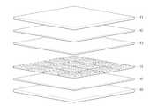
Translated fromKorean도 1은 종래의 백라이트장치를 도시한 도면이다.1 is a view showing a conventional backlight device.
도 2는 본 발명의 실시예에 따른 영상표시장치를 도시한 도면이다.2 is a diagram illustrating an image display device according to an exemplary embodiment of the present invention.
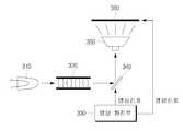
도 3은 본 발명의 실시예에 따른 영상표시장치를 구체적인 구성요소를 이용하여 나타낸 도면이다.3 is a diagram illustrating an image display device according to an embodiment of the present invention using specific components.
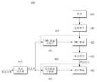
도 4은 도 3의 영상표시장치를 상세히 도시한 블록도이다.4 is a block diagram illustrating in detail the image display apparatus of FIG. 3.
도 5는 본 발명의 실시예에 따른 영상표시장치의 밝기조절과정을 나타낸 흐름도이다.5 is a flowchart illustrating a brightness control process of an image display apparatus according to an exemplary embodiment of the present invention.
*도면 중 주요부분에 대한 부호의 설명** Description of the symbols for the main parts of the drawings *
410: 영상처리부 420: DMD 패널부410: image processing unit 420: DMD panel unit
430: 램프 440: 집광렌즈430: lamp 440: condenser lens
450: 투사렌즈 460: 표시패널부450: projection lens 460: display panel portion
본 발명은 영상표시장치 및 그 밝기조절방법에 관한 것으로, 더욱 상세하게는 DMD를 이용하여 표시패널에 대한 백라이트를 제공하는 영상표시장치 및 그 밝기조절방법에 관한 것이다.The present invention relates to an image display apparatus and a brightness adjusting method thereof, and more particularly, to an image display apparatus providing a backlight for a display panel using a DMD and a brightness control method thereof.
일반적으로 영상표시장치는 TV, 노트북, 데스크 탑 컴퓨터 등의 모니터에 영상을 디스플레이하기 위해 사용되는 것이다. 이 중 액정표시장치는 스스로 빛을 발생시키지 못하기 때문에 별도의 광원으로부터 나오는 빛을 이용하여야 한다. 따라서 액정표시장치는 액정패널 후면에 광원을 형성하는 백라이트장치를 구비하여, 액정의 움직임에 따라 백라이트장치로부터 나오는 빛의 투과율을 조절함으로써 영상을 표현하도록 구성된다.In general, an image display device is used to display an image on a monitor such as a TV, a notebook computer, or a desktop computer. Among them, the liquid crystal display does not generate light by itself, and therefore, light from a separate light source should be used. Therefore, the liquid crystal display includes a backlight device that forms a light source on the back of the liquid crystal panel, and is configured to display an image by adjusting the transmittance of light emitted from the backlight device according to the movement of the liquid crystal.
도 1은 종래의 백라이트장치를 도시한 도면이다. 도 1을 참조하면, 투과되는 빛을 조절하여 화상을 표시하는 액정패널(11)과, 액정패널(11)의 하측에 일정한 간격을 갖고 빛을 집광하여 휘도를 높여주는 광학 시트(12)와, 광학 시트(12)의 하측에 빛을 산란시켜 균일한 빛으로 광학 시트(12) 전면에 조사하는 확산판(13)으로 구성되어 있다. 그리고 확산판(13)의 하측에는 빛을 발산하는 다수개의 분할된 램프(14)들이 구성되어 있고, 분할된 램프(14)들의 하측에 배면으로 향하는 빛을 전면으로 향하도록 하여 빛의 손실을 줄여 광 효율을 높여주는 반사판(15)이 구성되어 있으며, 반사판(15)의 하측에는 상기 구성들을 지지하는 케이스(16)가 구성되어 있다.1 is a view showing a conventional backlight device. Referring to Figure 1, the
도 1에 도시된 백라이트장치는 액정표시장치에서 요구되는 명암비를 높이기 위해 다수개의 블록단위로 분할된 램프를 사용하고 있다. 따라서 이들 다수개의 블록단위로 분할된 램프들을 구동하기 위해서는 구동회로가 블록단위로 구비되어 램프들의 밝기를 블록단위로 조절하도록 구성되어야 한다. 이는 구동회로가 복잡해지며, 블록이 많아질수록 구동회로도 많아지는 문제점을 발생시킨다. 또한, 블록단위로 분할한다 하더라도 그 수가 한정될 수 밖에 없어 블록단위로 구동되는 다수개의 램프에 의해 화면이 분할됨으로써 박진감있고 부드러운 영상을 표현하기에는 한계를 갖는다.The backlight device shown in FIG. 1 uses a lamp divided into a plurality of block units to increase the contrast ratio required in the liquid crystal display. Therefore, in order to drive the lamps divided into a plurality of block units, a driving circuit must be provided in block units to adjust brightness of the lamps in block units. This causes a problem that the driving circuit becomes complicated, and as the number of blocks increases, the driving circuit also increases. In addition, even if divided into block units, the number is limited, and the screen is divided by a plurality of lamps driven by the block unit, and thus there is a limit to expressing a vibrant and smooth image.
따라서 본 발명은 상기한 문제점은 해결하기 위한 것으로, 복수의 DMD를 이용하여 입사광을 표시패널로 반사시켜 표시패널에 대한 백라이트를 제공함으로써 명암비를 현저히 개선할 수 있는 영상표시장치 및 그 밝기조절방법을 제공함을 목적으로 한다.Accordingly, an aspect of the present invention is to solve the above-described problems, and an image display apparatus and a brightness control method of which a contrast ratio can be remarkably improved by providing a backlight for the display panel by reflecting incident light to the display panel using a plurality of DMDs. For the purpose of providing it.
상기한 목적을 달성하기 위한 본 발명에 따른 영상표시장치는 영상을 디스플레이하는 표시패널부; 및 복수의 DMD(Digital Micromirror Device)를 이용하여 입사광을 상기 표시패널부로 반사시켜 상기 표시패널부에 대한 백라이트를 제공하는 DMD 패널부를 포함한다.According to an aspect of the present invention, an image display device includes: a display panel unit configured to display an image; And a DMD panel unit reflecting incident light to the display panel unit by using a plurality of digital micromirror devices (DMDs) to provide a backlight for the display panel unit.
또한 바람직하게, 입력되는 영상신호를 처리하여 상기 표시패널부 및 상기 DMD 패널부로 전달하는 영상처리부를 더 포함한다.The method may further include an image processor which processes an input image signal and transmits the image signal to the display panel unit and the DMD panel unit.
또한 바람직하게, 상기 DMD 패널부는 상기 영상처리부로부터 출력된 영상신호를 기초로 상기 복수의 DMD 각각을 온/오프하여 상기 표시패널부에 대한 백라이트를 제공한다.Also, preferably, the DMD panel unit turns on / off each of the plurality of DMDs based on an image signal output from the image processor to provide a backlight for the display panel unit.
바람직하게, 상기 DMD 패널부로 입사되는 상기 입사광은 백색광이다.Preferably, the incident light incident on the DMD panel portion is white light.
또한 바람직하게, 상기 DMD 패널부의 상기 복수의 DMD 각각은 상기 표시패널부에 형성된 소정 개수의 픽셀에 대응하도록 구비된다.Also, preferably, each of the plurality of DMDs of the DMD panel unit may correspond to a predetermined number of pixels formed in the display panel unit.
바람직하게, 상기 DMD 패널부는 상기 표시패널부에 디스플레이되는 상기 영상에 대응하도록 상기 복수의 DMD 각각을 온/오프하여 상기 표시패널부에 대한 백라이트를 제공한다.Preferably, the DMD panel unit turns on / off each of the plurality of DMDs so as to correspond to the image displayed on the display panel unit to provide a backlight for the display panel unit.
또한 본 발명에 따른 영상표시장치의 밝기조절방법은 (a) 영상을 디스플레이하는 단계; 및 (b) 복수의 DMD(Digital Micromirror Device)를 이용하여 입사광을 표시패널부로 반사시켜 상기 표시패널부에 대한 백라이트를 제공하는 단계를 포함한다.In addition, the brightness control method of the image display device according to the present invention comprises the steps of (a) displaying an image; And (b) reflecting incident light to the display panel unit by using a plurality of digital micromirror devices (DMDs) to provide a backlight for the display panel unit.
이하, 도면을 참조하여 본 발명을 상세히 설명하면 다음과 같다.Hereinafter, the present invention will be described in detail with reference to the accompanying drawings.
도 2는 본 발명에 따른 영상표시장치(200)를 개략적으로 도시한 도면이다. 본 발명에 따른 영상표시장치(200)는 DMD 패널부(210)와 표시패널부(220)를 포함한다.2 is a view schematically showing an
표시패널부(220)는 영상을 디스플레이하며, DMD 패널부(210)는 복수의 DMD(Digital Micromirror Device)를 이용하여 입사광을 표시패널부(220)로 반사시켜 표시패널부(220)에 대한 백라이트를 제공한다.The
여기서, DMD는 주로 DLP(Digital Light Processing) 텔레비전에 이용되는 반도체소자로서 온/오프의 두가지 전기적인 신호에 따라 마이크로-미러가 편향되어 입사광을 반사하도록 구성되며, PWM 방식으로 구동된다.Here, the DMD is a semiconductor device mainly used for digital light processing (DLP) televisions, and is configured to reflect the incident light by deflecting the micro-mirror according to two electrical signals of on / off and driven by a PWM method.
도 3은 본 발명에 따른 영상표시장치를 구체적인 구성요소를 이용하여 나타낸 도면이다. 먼저 램프(310)에서 발광된 빛이 집광렌즈(320)를 거쳐 DMD 패널(340)에 입사된다. 여기서의 집광렌즈(320)는 릴레이렌즈일 수 있으며, 렌즈(320)를 거친 빛은 칼라 휠을 거치지 않고 곧바로 DMD 패널(322)로 입사된다.3 is a view showing the image display device according to the present invention using specific components. First, the light emitted from the
DMD 패널(340)은 영상처리부(330)에서 처리된 영상신호를 받아 DMD 패널(340)에 구비된 복수의 DMD 각각을 온/오프하여 집광렌즈(320)를 거쳐 입사된 광의 반사량을 조절한다. 이때, 영상처리부(330)에서 처리되는 영상신호는 또한 표시패널부(360)로 전달된다. 여기서의 표시패널(360)은 액정패널일 수 있다. 따라서 영상표시장치에 표시되는 칼라영상은 표시패널(360)로 전달되는 영상신호에 의하여 표시패널(360)의 각 화소가 제어됨으로써 표시된다.The
DMD 패널(340)이 복수의 DMD를 이용하여 반사량을 조절하여 입사광을 반사하면, 투사렌즈(350)는 반사된 광을 표시패널(360)에 투사한다. 따라서 표시패널(360)에 표시되는 영상에 대응하는 백라이트가 제공될 수 있다.When the
도 4는 도 3의 영상표시장치를 좀 더 상세히 나타낸 블록도이다. 도 4를 참조하면, 영상표시장치(400)는 영상처리부(410), DMD 패널부(420), 램프(430), 집광 렌즈(440), 투사렌즈(450), 표시패널부(460)를 포함한다.4 is a block diagram illustrating the image display device of FIG. 3 in more detail. Referring to FIG. 4, the
영상처리부(410)는 입력되는 영상신호를 처리하여 DMD 패널부(420) 및 표시패널부(460)로 전달한다. 따라서 DMD 패널부(420) 및 표시패널부(460)는 동일한 영상신호를 입력받아 구동한다.The
DMD 패널부(420)의 DMD 패널구동부(421)는 영상처리부(410)로부터 수신한 영상신호를 DMD 패널(422)을 구동하기에 적합한 신호로 포맷팅하여 DMD 패널(422)을 구동한다.The
즉, 영상처리부(410)로부터 출력되는 R, G, B 신호를 PWM 시퀀스 신호로 포맷팅하여 DMD 패널(422)에 구비된 복수의 DMD 각각을 온/오프함으로써 DMD 패널(422)을 구동한다.That is, the
DMD 패널(422)에는 램프(430)에서 발광된 빛이 집광렌즈(440)를 거쳐 입사된다. 이때, DLP 텔레비전과는 달리 램프로부터 집광렌즈(440)에 집광된 빛은 칼라 휠을 거치지 않고 곧바로 DMD 패널(422)로 입사된다. 따라서 DMD 패널(422)로 입사되는 광은 램프에서 발광한 백색광이다. 칼라 휠은 DMD 패널(422)로부터 반사되는 광을 표시패널(462)에 대한 백라이트로 이용하는데 불필요하기 때문에 구성요소에서 제외된다.Light emitted from the
DMD 패널(422)은 DMD 패널구동부(421)의 구동에 따라 복수의 DMD 각각을 온/오프하여 집광렌즈(440)를 거쳐 입사된 광의 반사량을 조절한다. 따라서 DMD 패널(422)에서 반사되는 광은 256계조의 그레이 스케일 영상으로 표현될 수 있다.The
DMD 패널(422)의 복수의 DMD 각각은 표시패널(462)에 형성된 소정 개수의 픽 셀에 대응하도록 DMD 패널(422)에 구비된다. 예를 들어, 표시패널이 풀HD급인 1920×1080의 해상도를 갖는다면, DMD 패널도 표시패널의 픽셀 수와 동일한 수의 DMD를 갖는 패널이 이용될 수 있다.Each of the plurality of DMDs of the
또한 표시패널의 해상도보다는 낮은 해상도의 DMD 패널을 이용하더라도 명암비 개선효과가 크게 저해되지 않으므로, 표시패널의 해상도보다는 다소 낮은 해상도의 DMD 패널이 이용되더라도 무방하다. 따라서, DMD 패널(422)에 구비되는 복수의 DMD 각각은 표시패널(462)에 형성된 소정 개수의 픽셀에 대응하도록 구비된다.In addition, even if a DMD panel having a lower resolution than that of the display panel is used, a contrast improvement effect is not significantly impaired. Therefore, a DMD panel having a somewhat lower resolution than the display panel resolution may be used. Accordingly, each of the plurality of DMDs provided in the
따라서 복수의 DMD 각각을 DMD 패널구동부(421)의 구동신호에 따라 온/오프 구동하면, 표시패널(462)에 표시되는 영상에 대응한 백라이트를 제공할 수 있게 된다.Accordingly, when each of the plurality of DMDs is driven on / off according to the driving signal of the
즉, 표시패널(462)에 표시되는 영상이 부분적으로 밝은 영상이면, 동일한 영상신호에 기초하여 구동되는 DMD 패널(422)로부터 표시패널에 반사되어 형성되는 영상도 해당 부분이 밝은 흑백의 영상으로 표현된다. 따라서 종래의 백라이트장치가 블럭단위 구동에 의하여 달성하려는 효과를 다수개의 램프와 그에 대한 별도의 구동회로를 구비하지 않고도 달성할 수 있게 된다.That is, when the image displayed on the
DMD 패널(422)이 복수의 DMD를 이용하여 반사량을 조절하여 입사광을 반사하면, 투사렌즈(450)는 반사된 광을 표시패널(462)에 투사한다. 따라서 표시패널(462)에 백라이트가 제공된다.When the
또한 표시패널(462)은 표시패널구동부(461)에 의해 칼라 영상이 디스플레이되도록 제어된다. 표시패널구동부(461)에는 영상처리부(410)에서 처리된 신호가 입 력되어 통상의 액정표시장치가 구동되는 방식에 의하여 표시패널(462)에 영상이 디스플레이된다.In addition, the
도 5는 본 발명의 실시예에 따른 영상표시장치의 밝기조절과정을 나타낸 흐름도이다. 도 5를 참조하면, 먼저 영상을 디스플레이한다(S510). 영상은 종래의 액정표시장치에서와 같이 영상처리부에서 처리된 신호가 표시패널구동부로 전달되어 표시패널이 구동됨으로써 표시패널에 디스플레이된다.5 is a flowchart illustrating a brightness control process of an image display apparatus according to an exemplary embodiment of the present invention. Referring to FIG. 5, an image is first displayed (S510). The image is displayed on the display panel by driving a display panel by transmitting a signal processed by the image processor to the display panel driver as in a conventional liquid crystal display.
다음으로, 복수의 DMD를 이용하여 표시패널에 백라이트를 제공한다(S520). 복수의 DMD는 표시패널에 형성된 소정 개수의 픽셀에 대응하도록 구비된다. 따라서 복수의 DMD 각각을 영상신호에 따라 온/오프하여 반사량을 조절하여 표시패널부로 백라이트를 제공하면, 표시패널에 디스플레이되는 영상에 대응하여 백라이트도 분할 구동되는 효과를 달성할 수 있다. 이는 종래의 백라이트장치가 램프를 블록단위로 분할하여 구동하는 방식에서 분할되는 블록 수에 한계를 갖는 반면 복수의 DMD를 구비하고 있는 DMD 패널을 이용하면 종래의 백라이트장치의 한계를 용이하게 극복할 수 있다.Next, a backlight is provided to the display panel using the plurality of DMDs (S520). The plurality of DMDs are provided to correspond to a predetermined number of pixels formed in the display panel. Accordingly, when each of the plurality of DMDs is turned on / off according to an image signal to adjust the reflection amount to provide a backlight to the display panel unit, the backlight may be dividedly driven in response to the image displayed on the display panel. This is because the conventional backlight device has a limit on the number of blocks to be divided in the manner of driving the lamp by dividing the block in blocks, while using a DMD panel having a plurality of DMD can easily overcome the limitation of the conventional backlight device have.
본 발명에 따르면, 복수의 DMD를 이용하여 입사광을 표시패널로 반사시켜 표시패널에 대한 백라이트를 제공함으로써 명암비를 현저히 개선할 수 있는 영상표시장치 및 그 밝기조절방법이 제공된다.According to the present invention, there is provided an image display apparatus and a method for adjusting brightness thereof, by which a plurality of DMDs are used to reflect incident light onto a display panel to provide a backlight for the display panel.
또한 본 발명에 따르면, 다수개의 램프나 구동회로를 구비하지 않고도 명암 비를 현저히 개선할 수 있으므로, 제조비용이 감소될 수 있다.In addition, according to the present invention, since the contrast ratio can be remarkably improved without having a plurality of lamps or driving circuits, the manufacturing cost can be reduced.
이상에서는 본 발명의 바람직한 실시예에 대하여 도시하고 설명하였으나, 본 발명은 상술한 특정의 실시예에 한정되지 아니하며, 본 발명의 요지를 벗어남이 없이 당해 발명이 속하는 기술분야에서 통상의 지식을 가진 자라면 누구든지 다양한 변형 실시가 가능함은 물론이고, 그와 같은 수정 또는 변형은 첨부하는 청구항의 기재범위 내에 있는 것이다.Although the above has been illustrated and described with respect to preferred embodiments of the present invention, the present invention is not limited to the above-described specific embodiments, and those skilled in the art without departing from the gist of the present invention. Anyone can make various modifications, as well as such modifications or variations are within the scope of the appended claims.
Claims (12)
Translated fromKoreanPriority Applications (4)
| Application Number | Priority Date | Filing Date | Title |
|---|---|---|---|
| KR1020070018993AKR20080079005A (en) | 2007-02-26 | 2007-02-26 | Image display device and brightness control method |
| US11/866,064US20080204394A1 (en) | 2007-02-26 | 2007-10-02 | Image display apparatus and method of adjusting brightness thereof |
| EP07123670AEP1962130A3 (en) | 2007-02-26 | 2007-12-19 | Image Display Apparatus and Method of Adjusting Brightness Thereof |
| CNA200710159934XACN101256741A (en) | 2007-02-26 | 2007-12-20 | Image display device and method for adjusting brightness thereof |
Applications Claiming Priority (1)
| Application Number | Priority Date | Filing Date | Title |
|---|---|---|---|
| KR1020070018993AKR20080079005A (en) | 2007-02-26 | 2007-02-26 | Image display device and brightness control method |
Publications (1)
| Publication Number | Publication Date |
|---|---|
| KR20080079005Atrue KR20080079005A (en) | 2008-08-29 |
Family
ID=39363932
Family Applications (1)
| Application Number | Title | Priority Date | Filing Date |
|---|---|---|---|
| KR1020070018993AWithdrawnKR20080079005A (en) | 2007-02-26 | 2007-02-26 | Image display device and brightness control method |
Country Status (4)
| Country | Link |
|---|---|
| US (1) | US20080204394A1 (en) |
| EP (1) | EP1962130A3 (en) |
| KR (1) | KR20080079005A (en) |
| CN (1) | CN101256741A (en) |
Cited By (5)
| Publication number | Priority date | Publication date | Assignee | Title |
|---|---|---|---|---|
| KR101050648B1 (en)* | 2008-12-02 | 2011-07-19 | 삼성전자주식회사 | Light-emitting device for portable communication device with DLP projection |
| KR20170015375A (en)* | 2014-05-30 | 2017-02-08 | 매직 립, 인코포레이티드 | Methods and system for creating focal planes in virtual and augmented reality |
| US11150489B2 (en) | 2014-01-31 | 2021-10-19 | Magic Leap, Inc. | Multi-focal display system and method |
| US11209651B2 (en) | 2014-01-31 | 2021-12-28 | Magic Leap, Inc. | Multi-focal display system and method |
| US11474355B2 (en) | 2014-05-30 | 2022-10-18 | Magic Leap, Inc. | Methods and systems for displaying stereoscopy with a freeform optical system with addressable focus for virtual and augmented reality |
Families Citing this family (2)
| Publication number | Priority date | Publication date | Assignee | Title |
|---|---|---|---|---|
| CN105282528B (en)* | 2014-07-17 | 2018-08-31 | 深圳市光峰光电技术有限公司 | digital micromirror device control device and projection display system |
| CN105182661B (en)* | 2015-08-26 | 2017-04-19 | 南京中科神光科技有限公司 | Single DMD projection device with white light source |
Family Cites Families (7)
| Publication number | Priority date | Publication date | Assignee | Title |
|---|---|---|---|---|
| EP1390806B1 (en)* | 2001-02-27 | 2010-08-25 | Dolby Laboratories Licensing Corporation | High dynamic range display devices |
| JP2002268014A (en)* | 2001-03-13 | 2002-09-18 | Olympus Optical Co Ltd | Image display device |
| JP4060162B2 (en)* | 2002-10-16 | 2008-03-12 | アストロデザイン株式会社 | Video projection device |
| US7218364B2 (en)* | 2003-10-31 | 2007-05-15 | Sony Ericsson Mobile Communications Ab | Dual mode liquid crystal displays (LCDs) with electromechanical reflective array |
| JP4168147B2 (en)* | 2004-03-11 | 2008-10-22 | 独立行政法人産業技術総合研究所 | Backlight device and method of manufacturing micromirror |
| KR100612011B1 (en)* | 2004-05-27 | 2006-08-11 | 삼성전자주식회사 | Method and apparatus for improving contrast of projection system |
| KR100698126B1 (en)* | 2005-07-01 | 2007-03-26 | 엘지전자 주식회사 | Power control device and method of display module |
- 2007
- 2007-02-26KRKR1020070018993Apatent/KR20080079005A/ennot_activeWithdrawn
- 2007-10-02USUS11/866,064patent/US20080204394A1/ennot_activeAbandoned
- 2007-12-19EPEP07123670Apatent/EP1962130A3/ennot_activeWithdrawn
- 2007-12-20CNCNA200710159934XApatent/CN101256741A/enactivePending
Cited By (9)
| Publication number | Priority date | Publication date | Assignee | Title |
|---|---|---|---|---|
| KR101050648B1 (en)* | 2008-12-02 | 2011-07-19 | 삼성전자주식회사 | Light-emitting device for portable communication device with DLP projection |
| US8197072B2 (en) | 2008-12-02 | 2012-06-12 | Samsung Electronics Co., Ltd | Light emitting device for portable communication device having digital light processing projector and liquid crystal display |
| US11150489B2 (en) | 2014-01-31 | 2021-10-19 | Magic Leap, Inc. | Multi-focal display system and method |
| US11209651B2 (en) | 2014-01-31 | 2021-12-28 | Magic Leap, Inc. | Multi-focal display system and method |
| US11520164B2 (en) | 2014-01-31 | 2022-12-06 | Magic Leap, Inc. | Multi-focal display system and method |
| KR20170015375A (en)* | 2014-05-30 | 2017-02-08 | 매직 립, 인코포레이티드 | Methods and system for creating focal planes in virtual and augmented reality |
| US11422374B2 (en) | 2014-05-30 | 2022-08-23 | Magic Leap, Inc. | Methods and system for creating focal planes in virtual and augmented reality |
| US11474355B2 (en) | 2014-05-30 | 2022-10-18 | Magic Leap, Inc. | Methods and systems for displaying stereoscopy with a freeform optical system with addressable focus for virtual and augmented reality |
| US12372794B2 (en) | 2014-05-30 | 2025-07-29 | Magic Leap, Inc. | Methods and systems for displaying stereoscopy with a freeform optical system with addressable focus for virtual and augmented reality |
Also Published As
| Publication number | Publication date |
|---|---|
| EP1962130A2 (en) | 2008-08-27 |
| US20080204394A1 (en) | 2008-08-28 |
| CN101256741A (en) | 2008-09-03 |
| EP1962130A3 (en) | 2008-10-22 |
Similar Documents
| Publication | Publication Date | Title |
|---|---|---|
| JP4552986B2 (en) | Image display device | |
| JP4901869B2 (en) | Image display device | |
| KR20080079005A (en) | Image display device and brightness control method | |
| JP5088665B2 (en) | Image display device | |
| JP2020107984A (en) | Image projection apparatus and control method thereof | |
| US20090109248A1 (en) | Display Apparatus Having a Multiplicity of Pixels and Method for Displaying Images | |
| US8152309B2 (en) | Image display apparatus, image display system, and image display method | |
| JP4552985B2 (en) | Image display device | |
| KR100612011B1 (en) | Method and apparatus for improving contrast of projection system | |
| CN112399157A (en) | Projector and projection method | |
| CN110956910A (en) | Projection device and projection method thereof | |
| TWI688808B (en) | Display device and backlight driving method | |
| KR20080109409A (en) | Projection type display device and display method applied thereto | |
| CN210465982U (en) | DLP projection system for enhancing dynamic contrast | |
| US9894334B2 (en) | Signal processing circuit, circuit substrate, and projector | |
| US9641819B2 (en) | Display device including a plurality of sub-signal processing circuits corresponding to a plurality of video signal colors, and method of controlling display device | |
| KR100725954B1 (en) | Portable projector using F. Elcos | |
| JP2020052380A (en) | Projection device and control method thereof | |
| KR100686147B1 (en) | Apparatus and method for controlling screen brightness of a projection display device | |
| KR100747230B1 (en) | Contour noise reduction device and plasma display device including same | |
| KR200423151Y1 (en) | Portable projector using F. Elcos | |
| JP2008058627A (en) | Projector and projection system | |
| JP2021189287A (en) | Image projection device | |
| JP2006293124A (en) | projector | |
| CN114257796A (en) | Projection device |
Legal Events
| Date | Code | Title | Description |
|---|---|---|---|
| PA0109 | Patent application | Patent event code:PA01091R01D Comment text:Patent Application Patent event date:20070226 | |
| PG1501 | Laying open of application | ||
| PC1203 | Withdrawal of no request for examination | ||
| WITN | Application deemed withdrawn, e.g. because no request for examination was filed or no examination fee was paid |