KR20080076628A - 3D image display device and method for improving stereoscopic image - Google Patents
3D image display device and method for improving stereoscopic imageDownload PDFInfo
- Publication number
- KR20080076628A KR20080076628AKR1020070016818AKR20070016818AKR20080076628AKR 20080076628 AKR20080076628 AKR 20080076628AKR 1020070016818 AKR1020070016818 AKR 1020070016818AKR 20070016818 AKR20070016818 AKR 20070016818AKR 20080076628 AKR20080076628 AKR 20080076628A
- Authority
- KR
- South Korea
- Prior art keywords
- parallax
- images
- adjustment
- point
- adjusted
- Prior art date
- Legal status (The legal status is an assumption and is not a legal conclusion. Google has not performed a legal analysis and makes no representation as to the accuracy of the status listed.)
- Ceased
Links
Images


Classifications
- E—FIXED CONSTRUCTIONS
- E05—LOCKS; KEYS; WINDOW OR DOOR FITTINGS; SAFES
- E05B—LOCKS; ACCESSORIES THEREFOR; HANDCUFFS
- E05B47/00—Operating or controlling locks or other fastening devices by electric or magnetic means
- E05B47/0001—Operating or controlling locks or other fastening devices by electric or magnetic means with electric actuators; Constructional features thereof
- E05B47/0012—Operating or controlling locks or other fastening devices by electric or magnetic means with electric actuators; Constructional features thereof with rotary electromotors
- H—ELECTRICITY
- H04—ELECTRIC COMMUNICATION TECHNIQUE
- H04N—PICTORIAL COMMUNICATION, e.g. TELEVISION
- H04N13/00—Stereoscopic video systems; Multi-view video systems; Details thereof
- H04N13/30—Image reproducers
- H04N13/398—Synchronisation thereof; Control thereof
- H—ELECTRICITY
- H04—ELECTRIC COMMUNICATION TECHNIQUE
- H04N—PICTORIAL COMMUNICATION, e.g. TELEVISION
- H04N13/00—Stereoscopic video systems; Multi-view video systems; Details thereof
- H04N13/10—Processing, recording or transmission of stereoscopic or multi-view image signals
- H04N13/106—Processing image signals
- H04N13/128—Adjusting depth or disparity
- E—FIXED CONSTRUCTIONS
- E05—LOCKS; KEYS; WINDOW OR DOOR FITTINGS; SAFES
- E05B—LOCKS; ACCESSORIES THEREFOR; HANDCUFFS
- E05B47/00—Operating or controlling locks or other fastening devices by electric or magnetic means
- E05B47/0001—Operating or controlling locks or other fastening devices by electric or magnetic means with electric actuators; Constructional features thereof
- E05B2047/0014—Constructional features of actuators or power transmissions therefor
- E05B2047/0018—Details of actuator transmissions
- E05B2047/002—Geared transmissions
- E—FIXED CONSTRUCTIONS
- E05—LOCKS; KEYS; WINDOW OR DOOR FITTINGS; SAFES
- E05B—LOCKS; ACCESSORIES THEREFOR; HANDCUFFS
- E05B63/00—Locks or fastenings with special structural characteristics
- E05B63/08—Mortise locks
- E—FIXED CONSTRUCTIONS
- E05—LOCKS; KEYS; WINDOW OR DOOR FITTINGS; SAFES
- E05B—LOCKS; ACCESSORIES THEREFOR; HANDCUFFS
- E05B9/00—Lock casings or latch-mechanism casings ; Fastening locks or fasteners or parts thereof to the wing
- E05B9/02—Casings of latch-bolt or deadbolt locks
Landscapes
- Engineering & Computer Science (AREA)
- Multimedia (AREA)
- Signal Processing (AREA)
- Testing, Inspecting, Measuring Of Stereoscopic Televisions And Televisions (AREA)
Abstract
Description
Translated fromKorean도 1은 본 발명의 일 실시예에 따른 입체영상 표시장치의 구성을 나타내는 블럭도,1 is a block diagram showing the configuration of a stereoscopic image display device according to an embodiment of the present invention;
도 2는 도 1의 입체영상 표시장치의 구성의 일 예를 나타내는 블럭도,2 is a block diagram illustrating an example of a configuration of a stereoscopic image display device of FIG. 1;
도 3a는 본 발명의 일 실시예에 따른 시차-발생 빈도의 히스토그램을 나타내는 모식도,3A is a schematic diagram showing a histogram of parallax-occurrence frequency according to an embodiment of the present invention;
도 3b는 본 발명의 일 실시예에 따른 시차-발생 빈도의 누적밀도 히스토그램을 나타내는 모식도,3B is a schematic diagram showing a cumulative density histogram of parallax-occurrence frequency according to an embodiment of the present invention;
도 4는 본 발명의 일 실시예에 따른 시차 조정 그래프를 나타내는 모식도,4 is a schematic diagram showing a parallax adjustment graph according to an embodiment of the present invention;
도 5는 본 발명의 일 실시예에 따른 입체영상 표시방법을 설명하기 위한 흐름도, 그리고,5 is a flowchart illustrating a stereoscopic image display method according to an embodiment of the present invention;
도 6은 본 발명의 다른 실시예에 따른 입체영상 표시방법을 설명하기 위한 흐름도이다.6 is a flowchart illustrating a stereoscopic image display method according to another embodiment of the present invention.
* 도면의 주요 부분에 대한 설명 *Description of the main parts of the drawing
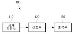
100 : 입체영상 표시장치 110 : 시차 추정부100: stereoscopic image display device 110: parallax estimation unit
120 : 산출부 121 : 제1생성부120: calculation unit 121: first generation unit
122 : 제2생성부 123 : 조정 시차 산출부122: second generation unit 123: adjusted parallax calculation unit
130 : 출력부 140 : 입력부130: output unit 140: input unit
본 발명은 입체영상 표시장치 및 그 방법에 관한 것으로, 보다 상세하게는 영상의 입체감을 향상시키기 위한 입체영상 표시장치 및 그 방법에 관한 것이다.The present invention relates to a stereoscopic image display device and a method thereof, and more particularly to a stereoscopic image display device and a method for improving the stereoscopic sense of the image.
일반적으로, 사람이 두 눈을 이용하여 하나의 피사체를 볼 때, 왼쪽 눈으로 보는 영상과 오른쪽 눈으로 보는 영상에는 두 눈의 간격에 해당하는 만큼 수평으로 위치 차이가 존재하게 되는데 이를 양안시차라고 한다. 이 경우, 사람의 두 눈에 보이는 실제 영상과 동일한 영상을 두 눈에 입력할 수 있다면 영상을 입체적으로 느낄 수 있게 된다. 이에 따라, 영상 제작시, 특성이 같은 동일한 두 대의 카메라를 양안 간격만큼(예를 들어, 65mm) 띄어 놓고 촬영한 후, 왼쪽 카메라로 찍은 영상은 왼쪽 눈에만 보이게 하고, 오른쪽 카메라로 찍은 영상은 오른쪽 눈에만 보이게 하여 입체적인 영상을 제작할 수 있게 된다. 이 경우, 시차보정을 위해 왼쪽 카메라로 찍은 영상을 오른쪽으로 이동시켜 해당 영상이 앞으로 돌출되어 있는 것처럼 보이도록 할 수 있다. 또한, 오른쪽 카메라로 찍은 영상을 왼쪽으로 이동시켜 해당 영상이 뒤로 들어가 있는 것처럼 보이도록 할 수 있게 된다. 이에 따라, 시차 보정을 통해 보다 입체적인 영상을 제작할 수 있게 된다.In general, when a person looks at a subject using both eyes, the positional difference exists horizontally as much as the distance between the two eyes in the image viewed by the left eye and the image viewed by the right eye, which is called binocular disparity. . In this case, if the same image as the actual image visible to the human eyes can be input to both eyes, the image can be three-dimensionally felt. Accordingly, when making an image, two cameras having the same characteristics are spaced apart (for example, 65 mm) by both eyes, and the image taken by the left camera is visible only to the left eye, and the image taken by the right camera is You can make a three-dimensional image by making it visible only to the eyes. In this case, the image taken by the left camera may be moved to the right for parallax correction so that the image may appear to protrude forward. In addition, the image taken with the right camera can be moved to the left so that the image looks as if it is back. Accordingly, it is possible to produce more three-dimensional images through parallax correction.
한편, 이와 같이 양안식 카메라 또는 컴퓨터 그래픽을 통해 입체 영상을 제작한다 하더라도, 상기 입체 영상을 표시하는 장치의 특성에 따라 영상의 입체감이 제대로 표현되지 않을 수 있게 된다. 즉, 입체 영상의 제작 환경과 디스플레이 환경을 차이로 인해 사용자는 영상의 입체감을 제대로 느낄 수가 없게 된다는 문제점이 있다.Meanwhile, even when a stereoscopic image is produced through a binocular camera or computer graphic, the stereoscopic sense of the image may not be properly expressed according to the characteristics of the device displaying the stereoscopic image. That is, due to the difference between the production environment of the stereoscopic image and the display environment, there is a problem that the user cannot properly sense the stereoscopic sense of the image.
본 발명은 상술한 바와 같은 문제점을 해결하기 위한 것으로, 본 발명의 목적은, 제1 및 제2영상의 시차를 추정하여 생성된 히스토그램을 이용함으로써, 제1 및 제2영상의 시차를 조정하여 영상의 입체감을 향상시킬 수 있는 입체영상 표시장치 및 그 방법을 제공함에 있다.The present invention is to solve the above problems, an object of the present invention, by using the histogram generated by estimating the parallax of the first and second image, by adjusting the parallax of the first and second image The present invention provides a three-dimensional image display device and a method for improving the stereoscopic sense of the.
이상과 같은 기술적 과제를 달성하기 위한 본 발명의 일 실시예에 따른 입체영상 표시장치는, 동일 피사체를 서로 다른 방향에서 촬상한 제1 및 제2영상 간의 시차를 추정하는 시차 추정부, 상기 추정된 시차의 발생 빈도를 산출하여 얻어지는 히스토그램을 이용하여, 상기 제1 및 제2영상에 대한 조정 시차를 산출하는 산출부, 및, 상기 산출된 조정 시차를 상기 제1 및 제2영상에 적용하여 출력하는 출력부를 포함한다.According to an aspect of the present invention, a stereoscopic image display apparatus includes a parallax estimator estimating a parallax between a first image and a second image of a same subject photographed in different directions, and the estimated A calculation unit for calculating an adjusted parallax for the first and second images using a histogram obtained by calculating a frequency of occurrence of parallax, and applying the calculated parallax to the first and second images and outputting the adjusted parallax. It includes an output unit.
이 경우, 상기 산출부는, 상기 제1 및 제2영상을 구성하는 각 픽셀들 중 동일 시차를 가지는 픽셀의 개수를 확인하여, 시차 별 발생 빈도를 나타내는 상기 히스토그램을 생성하는 제1 생성부, 상기 생성된 히스토그램을 누적시켜 누적 밀도 히스토그램을 생성하는 제2 생성부, 및, 상기 누적 밀도 히스토그램의 평균값, 상기 시차의 최소값 및 최대값을 이용하여 입력 시차 및 조정 시차 관계를 설정하고, 설정된 관계에 따라 상기 조정 시차를 산출하는 조정 시차 산출부를 포함할 수 있다.In this case, the calculation unit may include: a first generation unit generating the histogram indicating the frequency of occurrence of each parallax by checking the number of pixels having the same parallax among the pixels constituting the first and second images; A second generation unit which accumulates the histograms to generate a cumulative density histogram, and sets an input parallax and an adjusted parallax relationship by using the average value of the cumulative density histogram, the minimum value and the maximum value of the parallax, An adjustment parallax calculation unit for calculating the adjustment parallax may be included.
한편, 상기 조정 시차 산출부는, 상기 누적 밀도 히스토그램의 평균값을 기준으로 상기 최소값과의 사이에서 설정된 제1지점과 최소 입력 시차를 연결하는 제1 직선 그래프, 상기 누적 밀도 히스토그램의 평균값을 기준으로 상기 최대값과의 사이에서 설정된 제2지점과 최대 조정 시차를 연결하는 제2 직선 그래프, 및, 상기 제1지점 및 제2지점을 연결하며 기울기 1을 가지는 제3 직선 그래프로 표현되는 입력 시차 및 조정 시차 관계를 설정할 수 있다.The adjusted parallax calculating unit may further include: a first linear graph connecting the first point set between the minimum value and the minimum input parallax between the minimum value based on the average value of the cumulative density histogram and the maximum value based on the average value of the cumulative density histogram; An input parallax and an adjusted parallax represented by a second linear graph connecting the second adjusted point and the maximum adjusted parallax between values, and a third linear graph connecting the first and second points and having a slope of 1; You can establish a relationship.
사용자 선택 신호를 입력받는 입력부를 더 포함할 수 있으며, 상기 조정 시차 산출부는 상기 제1지점 및 상기 제2지점을 상기 사용자 선택 신호에 따라 변경하는 것이 바람직하다.The apparatus may further include an input unit configured to receive a user selection signal, and the adjustment time difference calculator may change the first point and the second point according to the user selection signal.
한편, 상기 시차 추정부는, 상기 제1 및 제2영상 중 매칭되는 지점을 탐색하여, 탐색된 지점 간의 시차를 추정할 수 있다.The disparity estimator may estimate a disparity between the searched points by searching for matching points among the first and second images.
본 발명의 일 실시예에 따른 입체영상 표시방법은, 동일 피사체를 서로 다른 방향에서 촬상한 제1 및 제2영상 간의 시차를 추정하는 단계, 상기 추정된 시차의 발생 빈도를 산출하여 얻어지는 히스토그램을 이용하여, 상기 제1 및 제2영상에 대한 조정 시차를 산출하는 단계, 및, 상기 산출된 조정 시차를 상기 제1 및 제2영상에 적용하여 출력하는 단계를 포함한다.In the stereoscopic image display method according to an embodiment of the present invention, estimating a parallax between a first image and a second image capturing the same subject in different directions, and using a histogram obtained by calculating the occurrence frequency of the estimated parallax And calculating the adjusted parallax with respect to the first and second images, and applying the calculated adjusted parallax to the first and second images and outputting the adjusted parallax.
이 경우, 상기 산출 단계는, 상기 제1 및 제2영상을 구성하는 각 픽셀들 중 동일 시차를 가지는 픽셀의 개수를 확인하여, 시차 별 발생 빈도를 나타내는 상기 히스토그램을 생성하는 제1 생성 단계, 상기 생성된 히스토그램을 누적시켜 누적 밀도 히스토그램을 생성하는 제2 생성 단계, 및, 상기 누적 밀도 히스토그램의 평균값, 상기 시차의 최소값 및 최대값을 이용하여 입력 시차 및 조정 시차 관계를 설정하고, 설정된 관계에 따라 상기 조정 시차를 산출하는 단계를 포함할 수 있다.In this case, the calculating step may include a first generation step of generating the histogram indicating the frequency of occurrence of each parallax by checking the number of pixels having the same parallax among the pixels constituting the first and second images; A second generation step of accumulating the generated histogram to generate a cumulative density histogram; and setting an input parallax and an adjusted parallax relationship using the average value of the cumulative density histogram, the minimum value and the maximum value of the parallax, and according to the set relationship. Calculating the adjustment parallax.
한편, 상기 산출 단계는, 상기 누적 밀도 히스토그램의 평균값을 기준으로 상기 최소값과의 사이에서 설정된 제1지점과 최소 입력 시차를 연결하는 제1 직선 그래프, 상기 누적 밀도 히스토그램의 평균값을 기준으로 상기 최대값과의 사이에서 설정된 제2지점과 최대 조정 시차를 연결하는 제2 직선 그래프, 및, 상기 제1지점 및 제2지점을 연결하며 기울기 1을 가지는 제3 직선 그래프로 표현되는 입력 시차 및 조정 시차 관계를 설정할 수 있다.The calculating step may include: a first linear graph connecting a first point set between the minimum value and the minimum input parallax between the minimum value based on the average value of the cumulative density histogram and the maximum value based on the average value of the cumulative density histogram; An input parallax and an adjusted parallax relationship represented by a second linear graph connecting the second adjusted point and the maximum adjusted parallax between and a third linear graph connecting the first and second points and having a slope of 1; Can be set.
사용자 선택 신호를 입력받는 단계를 더 포함할 수 있으며, 상기 산출 단계는, 상기 제1지점 및 상기 제2지점을 상기 사용자 선택 신호에 따라 변경하는 것이 바람직하다.The method may further include receiving a user selection signal, and the calculating step may include changing the first point and the second point according to the user selection signal.
한편, 상기 시차 추정 단계는, 상기 제1 및 제2영상 중 매칭되는 지점을 탐색하여, 탐색된 지점 간의 시차를 추정할 수 있다.In the disparity estimating step, the disparity between the searched points may be estimated by searching for a matching point among the first and second images.
본 발명의 다른 실시예에 따른 입체영상 표시장치는, 동일 피사체를 촬상한 제1 및 제2 영상의 시차를 확인하는 시차 추정부, 및, 상기 시차 추정부에 의해 확인된 시차를 이용하여 제1 및 제2 영상의 입체감을 조정하는 시차 조정부를 포함한 다.According to another embodiment of the present invention, a stereoscopic image display apparatus includes a parallax estimator that checks parallaxes of first and second images photographing the same subject, and a first image using a parallax identified by the parallax estimator. And a parallax adjustment unit that adjusts a three-dimensional effect of the second image.
상기 시차 조정부는, 각 구간 기울기가 상이하게 설정된 시차 및 조정 시차 간 매칭 그래프로부터, 상기 확인된 시차에 대응되는 조정 시차를 확인하고, 상기 확인된 조정 시차를 상기 제1 및 제2 영상에 적용하여 상기 입체감을 조정할 수 있게 된다.The disparity adjusting unit may determine an adjusting disparity corresponding to the identified disparity from the matching disparity between the disparity and the adjusting disparity matching graph, and applying the identified adjusting disparity to the first and second images. The three-dimensional effect can be adjusted.
이 경우, 상기 시차 조정부는, 상기 매칭 그래프의 각 구간의 범위 및 기울기를 사용자 선택 신호에 따라 변경하는 것이 바람직하다.In this case, the disparity adjusting unit may change the range and the slope of each section of the matching graph according to a user selection signal.
한편, 본 발명의 다른 실시예에 따른 입체영상 표시방법은, 동일 피사체를 촬상한 제1 및 제2 영상의 시차를 확인하는 단계, 및, 상기 확인된 시차를 이용하여 제1 및 제2 영상의 입체감을 조정하는 단계를 포함한다.On the other hand, the stereoscopic image display method according to another embodiment of the present invention, the step of confirming the parallax of the first and second images photographing the same subject, and using the identified parallax of the first and second image Adjusting the three-dimensional effect.
상기 입체감 조정 단계는, 각 구간 기울기가 상이하게 설정된 시차 및 조정 시차 간 매칭 그래프로부터, 상기 확인된 시차에 대응되는 조정 시차를 확인하고, 상기 확인된 조정 시차를 상기 제1 및 제2 영상에 적용하여 상기 입체감을 조정할 수 있다.The three-dimensional adjustment step may include determining a parallax corresponding to the identified parallax from a matching graph between parallaxes and adjustment parallaxes in which each section slope is different, and applying the identified parallax to the first and second images. To adjust the three-dimensional effect.
이 경우, 상기 입체감 조정 단계는, 상기 매칭 그래프의 각 구간의 범위 및 기울기를 사용자 선택 신호에 따라 변경하는 것이 바람직하다.In this case, the three-dimensional adjustment step, it is preferable to change the range and the slope of each section of the matching graph in accordance with the user selection signal.
이하에서는 첨부된 도면을 참조하여 본 발명을 보다 자세하게 설명한다.Hereinafter, with reference to the accompanying drawings will be described in detail the present invention.
도 1은 본 발명의 일 실시예에 따른 입체영상 표시장치의 구성을 나타내는 블럭도이다. 도 1을 참조하면, 본 입체영상 표시장치(100)는, 시차 추정부(110), 산출부(120) 및 출력부(130)를 포함한다.1 is a block diagram illustrating a configuration of a stereoscopic image display device according to an embodiment of the present invention. Referring to FIG. 1, the stereoscopic
시차 추정부(110)는 동일 피사체를 서로 다른 방향에서 촬상한 제1 및 제2영상 간의 시차(disparity)를 추정한다. 이 경우, 제1영상 및 제2영상은 촬상 장치의 두 렌즈를 사람의 양안시차(예를 들어, 65mm)만큼 띄워놓고 동일 피사체를 촬상한 영상으로, 제1 및 제2영상 중 어느 하나는 좌측에서 촬상한 좌(左)영상이 될 수 있으며, 다른 하나는 우측에서 촬상한 우(右)영상이 될 수 있다. 시차 추정부(110)는 좌영상과 우영상을 비교하여 매칭되는 지점 간의 시차를 추정한다.The
산출부(120)는 시차 추정부(110)를 통해 추정된 시차의 발생 빈도를 산출하여 얻어지는 히스토그램을 이용하여, 제1 및 제2영상에 대한 조정 시차를 산출한다. 이 경우, 추정된 시차의 발생 빈도란, 제1영상과 제2영상 간에 동일 시차가 몇 번이나 발생하였는지를 나타낸다. 산출부(120)는 시차 발생 빈도에 따른 히스토그램을 이용하여, 제1 및 제2영상에 대한 (-) 및 (+) 조정 시차를 산출하게 된다.The
출력부(130)는 산출부(120)를 통해 산출된 조정 시차를 제1 및 제2영상에 적용하여 출력한다. 즉, 산출된 조정 시차로 제1 및 제2영상의 시차를 조정함으로써, 제1 및 제2영상의 입체감을 조정하여 출력한다. 이 경우, 출력부(130)는 제1 및 제2영상의 시차 조정이 완료되면, 제1 및 제2영상을 합성하여 하나의 영상으로 생성하여 화면상에 출력한다.The
한편, 산출부(120) 및 출력부(130)는 시차를 조정하는 시차 조정부로 기능한다. 이 경우, 시차 조정부로 기능하는 산출부(120) 및 출력부(130)는 각 구간 기울기가 상이하게 설정된 시차 및 조정 시차 간 매칭 그래프로부터, 확인된 시차에 대응되는 조정 시차를 제1 및 제2영상에 적용하여 입체감을 조정한다. 이에 따라, 제 1 및 제2영상의 시차 조정으로, 보다 입체감이 향상된 영상을 화면상에 출력할 수 있다.On the other hand, the
도 2는 도 1의 입체영상 표시장치의 구성의 일 예를 구체적으로 나타내는 블럭도이다. 도 2를 참조하면, 본 입체영상 표시장치(100)는 시차 추정부(110), 산출부(120), 출력부(130) 및 입력부(140)를 포함한다.FIG. 2 is a block diagram illustrating in detail an example of a configuration of the 3D image display device of FIG. 1. 2, the stereoscopic
시차 추정부(110)는 동일 피사체를 서로 다른 방향에서 촬상한 제1 및 제2영상 간의 시차(disparity, 視差)를 추정한다. 이 경우, 시차 추정부(110)는 제1 및 제2영상 중 매칭되는 지점을 탐색하여, 탐색된 지점 간의 시차를 추정한다. 시차 추정 방법으로는, 제1 및 제2영상 중 좌영상을 m×n의 블록으로 분할하여 각 블록의 영상과 매칭되는 지점을, 제1 및 제2영상 중 우영상에서 탐색하여, 해당 지점 간의 시차를 추정하는 블록 기반에 따른 시차 추정 방법이 있을 수 있다. 또한, 블록이 아닌 픽셀 단위로 좌영상 및 우영상의 매칭 지점을 탐색하여, 해당 지점 간의 시차를 추정하는 픽셀 기반에 따른 시차 추정 방법이 있을 수 있다.The
입력부(140)는 사용자 선택 신호를 입력받는다.The
산출부(120)는 제1 및 제2영상의 시차 조정을 위한 조정 시차를 산출한다. 구체적으로, 산출부(120)는 제1생성부(121), 제2생성부(122), 조정 시차 산출부(123)를 포함한다.The
제1생성부(121)는 제1 및 제2영상을 구성하는 각 픽셀들 중 동일 시차를 가지는 픽셀의 개수를 확인하여, 시차 별 발생 빈도를 나타내는 히스토그램을 생성한다. 예를 들어, 제1 및 제2영상 중 소정 지점의 픽셀 간의 시차가 -20인 경우, -20 의 시차가 1번 발생하였음을 히스토그램 상에 표시한다. 이와 같은 방식으로 제1 및 제2영상의 시차 별 발생 빈도를 나타내는 히스토그램을 생성할 수 있다.The
제2생성부(122)는 제1생성부(121)를 통해 생성된 히스토그램을 누적시켜 누적 밀도 히스토그램을 생성한다.The
조정 시차 산출부(123)는 시차를 조정하기 위한 조정 시차를 산출하기 위한 것으로, 제2생성부(122)를 통해 생성된 누적 밀도 히스토그램의 평균값, 시차의 최소값 및 최대값을 이용하여 입력 시차 및 조정 시차 관계를 설정한다. 또한, 조정 시차 산출부(123)는 설정된 조정 시차 관계에 따라 조정 시차를 산출한다. 구체적으로, 조정 시차 산출부(123)는 누적 밀도 히스토그램의 평균값을 기준으로 최소값과의 사이에서 설정된 제1지점과 최소 입력 시차를 연결하는 제1 직선 그래프를 표현한다. 또한, 누적 밀도 히스토그램의 평균값을 기준으로 최대값과의 사이에서 설정된 제2지점과 최대 조정 시차를 연결하는 제2 직선 그래프를 표현하며, 제1지점 및 제2지점을 연결하며 기울기 1을 가지는 제3 직선 그래프를 표현하여 입력 시차 및 조정 시차 관계를 설정한다. 이 경우, 누적 밀도 히스토그램의 평균값을 기준으로 최소값 및 최대값 사이에서 설정된 제1지점 및 제2지점을 입력부(140)를 통해 사용자 선택 신호에 따라 변경될 수 있다.The adjusted
한편, 제1 내지 제3 직선 그래프는 입력 시차에 따른 출력 시차, 즉, 조정 시차를 산출하기 위한 것이다. 조정 시차 산출부(123)는 제1 내지 제3 직선 그래프 상에서 (-) 및 (+) 조정 시차를 산출할 수 있다. 제1 내지 제3직선 그래프를 이용하여 (-) 및 (+) 조정 시차를 산출할 경우, 조정 시차 산출부(123)는 시차 추정 부(110)를 통해 추정된 제1 및 제2영상의 (-) 시차보다 큰 (-)시차를 산출하며, 시차 추정부(110)를 통해 추정된 제1 및 제2영상의 (+) 시차보다 큰 (+) 시차를 산출할 수 있게 된다.On the other hand, the first to third linear graphs are for calculating the output parallax according to the input parallax, that is, the adjustment parallax. The adjustment
출력부(130)는 조정 시차 산출부(123)를 통해 산출된 (-) 및 (+) 조정 시차로 제1 및 제2영상 간의 시차를 새로이 조정한 후, 제1 및 제2영상을 합성하여 화면상에 출력한다. 이에 따라, 제1 및 제2영상의 시차 조정으로 보다 입체감이 향상된 영상을 화면상에 출력할 수 있게 된다.The
도 3a는 본 발명의 일 실시예에 따른 시차-발생 빈도의 히스토그램을 나타내는 모식도이다. 도 3a를 참조하면, 히스토그램(200)은 제1 및 제2영상, 즉, 좌영상 및 우영상을 구성하는 각 픽셀들 중 동일 시차를 가지는 픽셀의 개수에 따른 시차 별 발생 빈도를 나타낸다. 히스토그램(200)을 참조하면, 제1및 제2영상의 각 픽셀들 중 -40의 시차는 10번 정도 발생하며, 0의 시차는 85번 정도 발생하며, 80의 시차는 12번 정도 발생하는 것을 알 수 있다.3A is a schematic diagram showing a histogram of parallax-occurrence frequency according to an embodiment of the present invention. Referring to FIG. 3A, the
도 3b는 본 발명의 일 실시예에 따른 시차-발생 빈도의 누적밀도 히스토그램을 나타내는 모식도이다. 도 3b를 참조하면, 누적 밀도 히스토그램(300)은 도 3a에 도시된 히스토그램(200)을 차례로 누적시킨 시차 별 발생 빈도를 나타낸다. 이 경우, 누적 밀도 히스토그램(300)을 참조하면, 제1 및 제2영상 간의 시차 최소값은 -40이며, 최대값은 80인 것을 알 수 있다. 이와 같이, 히스토그램(200) 및 누적 밀도 히스토그램(300)을 이용하여 제1 및 제2영상 간의 시차에 대한 최소값 및 최대값을 알 수 있다.3B is a schematic diagram showing a cumulative density histogram of parallax-occurrence frequency according to an embodiment of the present invention. Referring to FIG. 3B, the
도 4는 본 발명의 일 실시예에 따른 시차 조정 그래프를 나타내는 모식도이다. 도 4를 참조하면, 시차 조정 그래프는 입력 시차 및 조정 시차 관계를 나타낸 것으로, 각 구간 기울기가 상이하게 설정된 시차 및 조정 시차 간 매칭 그래프이다. 구체적으로, 시차 조정 그래프의 y축은 제1 및 제2영상의 입력 시차를 나타내며, 시차 조정 그래프의 x축은 제1 및 제2영상의 출력 시차, 즉, 조정 시차를 나타낸다.4 is a schematic diagram illustrating a parallax adjustment graph according to an embodiment of the present invention. Referring to FIG. 4, the parallax adjustment graph illustrates a relationship between input parallax and adjustment parallax, and is a matching graph between parallax and adjustment parallax in which each section slope is set differently. Specifically, the y axis of the parallax adjustment graph represents input parallax of the first and second images, and the x axis of the parallax adjustment graph represents output parallax of the first and second images, that is, the adjustment parallax.
시차 조정 그래프는, 입력 시차의 최소값 내지 최대값에 대응되는 출력 시차를 출력하기 위해 a지점 및 b지점을 직선 그래프로 표현한다. 이 경우, 도 3b에 도시된 누적 밀도 히스토그램의 평균값을 기준으로 최소값과의 사이에 제1지점을 설정할 수 있으며, 평균값을 기준으로 최대값과의 사이에 제2지점을 설정할 수 있다. 이에 따라, 최소 조정 시차를 연결한 제1직선 그래프를 표현할 수 있으며, 제2지점과 최대 조정 시차를 연결한 제2직선 그래프를 표현할 수 있게 된다. 이에 따라, 제1직선 그래프 및 제2직선 그래프는 a지점 및 b지점을 연결한 직선 그래프에 비해 큰 기울기를 가지므로 조정 시차를 산출할 수 있다.The parallax adjustment graph expresses point a and point b in a straight line graph to output an output parallax corresponding to the minimum value or the maximum value of the input parallax. In this case, the first point may be set between the minimum value based on the average value of the cumulative density histogram illustrated in FIG. 3B, and the second point may be set between the maximum value based on the average value. Accordingly, the first linear graph connecting the minimum adjustment parallax may be expressed, and the second linear graph connecting the second point and the maximum adjusting parallax may be expressed. Accordingly, since the first linear graph and the second linear graph have larger inclinations than the linear graph connecting the points a and b, the adjustment parallax can be calculated.
제1직선 그래프를 이용하여 조정 시차를 산출할 경우, 제1지점에 해당하는 입력 시차와 최소값 사이의 제1 및 제2영상의 입력 시차는 제1직선 그래프에 따른 출력 시차, 즉, 조정 시차를 산출할 수 있다. 또한, 제2직선 그래프를 이용하여 조정 시차를 산출할 경우, 제2지점에 해당하는 입력 시차와 최대값 사이의 제1 및 제2영상의 시차는 제2직선 그래프에 따른 조정 시차를 산출할 수 있게 된다.When calculating the adjusted parallax using the first linear graph, the input parallax of the first and second images between the input parallax corresponding to the first point and the minimum value is determined by the output parallax according to the first linear graph, that is, the adjusted parallax. Can be calculated. In addition, when the adjusted parallax is calculated using the second linear graph, the parallax of the first and second images between the input parallax corresponding to the second point and the maximum value may calculate the adjusted parallax according to the second linear graph. Will be.
한편, 제1지점 및 제2지점을 연결하여 예를 들어, 1의 기울기를 가지는 제3 직선 그래프를 표현할 수 있다. 제3직선 그래프에 해당하는 구간에서는 입력 시차는 그대로 출력 시차로 산출되게 된다. 제3직선 그래프는 반드시 1의 기울기는 가질 필요는 없으며, 제1 및 제2 직선 그래프의 기울기와 비교했을 때, 보다 작은 기울기를 가지는 것이 바람직하다.On the other hand, by connecting the first point and the second point, for example, a third linear graph having a slope of 1 can be represented. In the section corresponding to the third linear graph, the input parallax is calculated as the output parallax as it is. The third linear graph does not necessarily have to have a slope of 1, and it is preferable to have a smaller slope as compared with the slope of the first and second straight graphs.
상기 제1지점 및 제2지점 및 기울기는 사용자 선택 신호에 따라 변경될 수 있는 것으로, 제1 및 제2영상의 시차를 전반적으로 조정하고자 할 경우에는, 평균값에 가깝게 제1지점 및 제2지점을 변경할 수 있다. 한편, 제1지점 및 제2지점은 입체영상 표시장치(100)의 제작 당시, 소정 프로그램에 의해 적정 수준에서 설정될 수 있도록 설계할 수도 있다.The first point, the second point, and the slope may be changed according to a user selection signal. When the parallax of the first and second images is to be adjusted as a whole, the first and second points may be closer to the average value. You can change it. Meanwhile, the first point and the second point may be designed to be set at an appropriate level by a predetermined program at the time of manufacturing the stereoscopic
도 5는 본 발명의 일 실시예에 따른 입체영상 표시방법을 설명하기 위한 흐름도이다. 도 5를 참조하면, 입체영상 표시장치(100)는 제1 및 제2영상 간의 시차를 추정한다(S510). 이 경우, 제1 및 제2영상은, 촬상 장치의 두 렌즈를 이용하여 동일 피사체를 서로 다른 방향에서 촬상한 것으로, 좌영상 및 우영상이 될 수 있다. 입체영상 표시장치(100)는 제1 및 제2영상 중 매칭되는 시점을 탐색하여, 탐색된 지점 간의 시차를 추정할 수 있다. 시차 추정 방법의 예로는, 블록 기반에 따른 시차 추정 방법 및 픽셀 기반에 따른 시차 추정 방법이 있을 수 있다.5 is a flowchart illustrating a stereoscopic image display method according to an embodiment of the present invention. Referring to FIG. 5, the 3D
다음, 입체영상 표시장치(100)는 추정된 시차의 발생 빈도를 산출하여 얻어지는 히스토그램을 이용하여, 제1 및 제2영상에 대한 조정 시차를 산출한다(S520). 이 경우, 입체영상 표시장치(100)는 시차 발생 빈도에 따른 히스토그램을 이용하여, 제1 및 제2영상의 조정 시차를 산출하게 된다.Next, the 3D
이 후, 입체영상 표시장치(100)는 산출된 조정 시차를 제1 및 제2영상에 적용하여 출력한다(S530). 이 경우, 제1 및 제2영상의 시차 조정이 완료되면, 제1 및 제2영상을 합성하여 하나의 영상으로 생성하여 화면상에 출력한다. 이에 따라, 제1 및 제2영상의 시차 조정으로, 보다 입체적인 영상을 화면상에 출력할 수 있다.Thereafter, the 3D
도 6은 본 발명의 다른 실시예에 따른 입체영상 표시방법을 설명하기 위한 흐름도이다. 도 6을 참조하면, 입체영상 표시장치(100)는 제1 및 제2영상 간의 시차를 추정한다(S610).6 is a flowchart illustrating a stereoscopic image display method according to another embodiment of the present invention. Referring to FIG. 6, the 3D
다음, 입체영상 표시장치(100)는 제1 및 제2영상의 시차 별 발생 빈도를 나타내는 히스토그램을 생성한다(S620). 구체적으로, 제1 및 제2영상을 구성하는 각 픽셀들 중 동일 시차를 가지는 픽셀의 개수를 확인하여, 시차 별 발생 빈도를 나타내는 히스토그램을 생성할 수 있다. 이 후, 입체영상 표시장치(100)는 히스토그램을 누적시켜 누적 밀도 히스토그램을 생성한다(S630).Next, the 3D
한편, 입체영상 표시장치(100)는 입력 시차 및 조정 시차 관계를 설정한다(S640). 구체적으로, 누적 밀도 히스토그램의 평균값, 시차의 최소값 및 최대값을 이용하여 입력 시차 및 조정 시차 관계를 설정할 수 있다. 이 경우, 조정 시차 관계는, 제1 및 제2영상의 입력 시차에 매칭된 조정 시차를 직선 그래프로 표현할 수 있다.On the other hand, the stereoscopic
입체영상 표시장치(100)는 입력 시차 및 조정 시차 관계에 따라 조정 시차를 산출한다(S650).The stereoscopic
입체영상 표시장치(100)는 제1 및 제2영상에 산출된 조정 시차를 적용하여 화면상에 출력한다(S660). 이 경우, 입체영상 표시장치(100)는 조정 시차가 적용된 제1 및 제2영상을 합성하여 하나의 영상으로 형성하여 화면상에 출력할 수 있게 된다.The stereoscopic
이와 같이, 입력 시차 및 조정 시차 관계에 따라 제1 및 제2영상의 출력 시차를 조정하는 방식에 따라, 제1 및 제2영상 중 (+) 시차 및 (-) 시차를 조정함으로써, 보다 입체감 있는 영상을 화면상에 출력할 수 있게 된다.As described above, the positive and negative parallaxes of the first and second images are adjusted according to a method of adjusting the output parallax of the first and second images according to the input parallax and the adjustment parallax relationship. The image can be output on the screen.
이상 설명한 바와 같이, 본 발명에 따르면, 입체영상 표시장치가 입력되는 제1 및 제2영상에 대한 조정 시차에 따라 시차를 조정함으로써, 입력되는 영상을 보다 입체적으로 화면상에 출력할 수 있게 된다. 이에 따라, 사용자는 영상 시청에 있어서, 보다 입체감이 향상된 영상을 시청할 수 있게 된다.As described above, according to the present invention, by adjusting the parallax according to the adjustment parallax with respect to the first and second images input, the stereoscopic image display device can be output to the screen more three-dimensionally. Accordingly, the user can watch a video with improved stereoscopic feeling in viewing a video.
이상에서는 본 발명의 바람직한 실시예에 대하여 도시하고 설명하였지만, 본 발명은 상술한 특정의 실시예에 한정되지 아니하며, 청구범위에서 청구하는 본 발명의 요지를 벗어남이 없이 당해 발명이 속하는 기술분야에서 통상의 지식을 가진자에 의해 다양한 변형실시가 가능한 것은 물론이고, 이러한 변형실시들은 본 발명 의 기술적 사상이나 전망으로부터 개별적으로 이해되어져서는 안될 것이다.While the above has been shown and described with respect to preferred embodiments of the present invention, the present invention is not limited to the specific embodiments described above, it is usually in the technical field to which the invention belongs without departing from the spirit of the invention claimed in the claims. Various modifications can be made by those skilled in the art, and these modifications should not be individually understood from the technical spirit or the prospect of the present invention.
Claims (16)
Translated fromKoreanPriority Applications (4)
| Application Number | Priority Date | Filing Date | Title |
|---|---|---|---|
| KR1020070016818AKR20080076628A (en) | 2007-02-16 | 2007-02-16 | 3D image display device and method for improving stereoscopic image |
| US11/857,027US20080199070A1 (en) | 2007-02-16 | 2007-09-18 | Three-dimensional image display apparatus and method for enhancing stereoscopic effect of image |
| CNA2007101524220ACN101247530A (en) | 2007-02-16 | 2007-10-11 | Three-dimensional image display device and method for enhancing image stereoscopic effect |
| EP07122602AEP1968329A3 (en) | 2007-02-16 | 2007-12-07 | Three-dimensional image display apparatus and method for enhancing stereoscopic effect of image |
Applications Claiming Priority (1)
| Application Number | Priority Date | Filing Date | Title |
|---|---|---|---|
| KR1020070016818AKR20080076628A (en) | 2007-02-16 | 2007-02-16 | 3D image display device and method for improving stereoscopic image |
Publications (1)
| Publication Number | Publication Date |
|---|---|
| KR20080076628Atrue KR20080076628A (en) | 2008-08-20 |
Family
ID=39020775
Family Applications (1)
| Application Number | Title | Priority Date | Filing Date |
|---|---|---|---|
| KR1020070016818ACeasedKR20080076628A (en) | 2007-02-16 | 2007-02-16 | 3D image display device and method for improving stereoscopic image |
Country Status (4)
| Country | Link |
|---|---|
| US (1) | US20080199070A1 (en) |
| EP (1) | EP1968329A3 (en) |
| KR (1) | KR20080076628A (en) |
| CN (1) | CN101247530A (en) |
Cited By (1)
| Publication number | Priority date | Publication date | Assignee | Title |
|---|---|---|---|---|
| KR101241654B1 (en)* | 2011-07-18 | 2013-03-11 | 한국과학기술원 | Apparatus and method for editing disparity graph of stereoscopic image, image processing apparatus, and recording medium |
Families Citing this family (51)
| Publication number | Priority date | Publication date | Assignee | Title |
|---|---|---|---|---|
| KR101345303B1 (en)* | 2007-03-29 | 2013-12-27 | 삼성전자주식회사 | Dynamic depth control method or apparatus in stereo-view or multiview sequence images |
| JP4737573B2 (en)* | 2009-02-05 | 2011-08-03 | 富士フイルム株式会社 | 3D image output apparatus and method |
| JP5327524B2 (en)* | 2009-02-27 | 2013-10-30 | ソニー株式会社 | Image processing apparatus, image processing method, and program |
| KR20110005205A (en)* | 2009-07-09 | 2011-01-17 | 삼성전자주식회사 | Signal processing method and apparatus using screen size of display device |
| JP5249149B2 (en)* | 2009-07-17 | 2013-07-31 | 富士フイルム株式会社 | Stereoscopic image recording apparatus and method, stereoscopic image output apparatus and method, and stereoscopic image recording and output system |
| US8509519B2 (en)* | 2009-07-29 | 2013-08-13 | Intellectual Ventures Fund 83 Llc | Adjusting perspective and disparity in stereoscopic image pairs |
| KR20110018261A (en)* | 2009-08-17 | 2011-02-23 | 삼성전자주식회사 | Text subtitle data processing method and playback device |
| JPWO2011024373A1 (en)* | 2009-08-31 | 2013-01-24 | パナソニック株式会社 | Stereoscopic control device, integrated circuit, and stereoscopic control method |
| JP5444955B2 (en)* | 2009-08-31 | 2014-03-19 | ソニー株式会社 | Stereoscopic image display system, parallax conversion device, parallax conversion method, and program |
| JP5404263B2 (en)* | 2009-09-07 | 2014-01-29 | パナソニック株式会社 | Parallax calculation method and parallax calculation device |
| JP5299214B2 (en) | 2009-10-20 | 2013-09-25 | ソニー株式会社 | Image processing apparatus, image processing method, and program |
| US9128367B2 (en) | 2010-03-05 | 2015-09-08 | Panasonic Intellectual Property Management Co., Ltd. | 3D imaging device and 3D imaging method |
| JP5432365B2 (en)* | 2010-03-05 | 2014-03-05 | パナソニック株式会社 | Stereo imaging device and stereo imaging method |
| JP5444452B2 (en) | 2010-03-05 | 2014-03-19 | パナソニック株式会社 | Stereo imaging device and stereo imaging method |
| JP6073214B2 (en) | 2010-03-31 | 2017-02-01 | トムソン ライセンシングThomson Licensing | Method, apparatus and processor readable medium for processing parallax |
| US9030536B2 (en) | 2010-06-04 | 2015-05-12 | At&T Intellectual Property I, Lp | Apparatus and method for presenting media content |
| JP5556394B2 (en)* | 2010-06-07 | 2014-07-23 | ソニー株式会社 | Stereoscopic image display system, parallax conversion device, parallax conversion method, and program |
| KR101291071B1 (en)* | 2010-06-08 | 2013-08-01 | 주식회사 에스칩스 | Method And Apparatus for Impoving Stereoscopic Image Error |
| JP5494283B2 (en)* | 2010-06-24 | 2014-05-14 | ソニー株式会社 | 3D display device and 3D display device control method |
| EP2587812A4 (en)* | 2010-06-24 | 2014-02-26 | Korea Electronics Technology | METHOD FOR CONFIGURING A STEREOSCOPIC MOVIE IMAGE FILE |
| US8640182B2 (en) | 2010-06-30 | 2014-01-28 | At&T Intellectual Property I, L.P. | Method for detecting a viewing apparatus |
| US8593574B2 (en) | 2010-06-30 | 2013-11-26 | At&T Intellectual Property I, L.P. | Apparatus and method for providing dimensional media content based on detected display capability |
| US9787974B2 (en) | 2010-06-30 | 2017-10-10 | At&T Intellectual Property I, L.P. | Method and apparatus for delivering media content |
| US8918831B2 (en) | 2010-07-06 | 2014-12-23 | At&T Intellectual Property I, Lp | Method and apparatus for managing a presentation of media content |
| US9049426B2 (en) | 2010-07-07 | 2015-06-02 | At&T Intellectual Property I, Lp | Apparatus and method for distributing three dimensional media content |
| US9560406B2 (en) | 2010-07-20 | 2017-01-31 | At&T Intellectual Property I, L.P. | Method and apparatus for adapting a presentation of media content |
| US9232274B2 (en) | 2010-07-20 | 2016-01-05 | At&T Intellectual Property I, L.P. | Apparatus for adapting a presentation of media content to a requesting device |
| US9032470B2 (en) | 2010-07-20 | 2015-05-12 | At&T Intellectual Property I, Lp | Apparatus for adapting a presentation of media content according to a position of a viewing apparatus |
| US8994716B2 (en) | 2010-08-02 | 2015-03-31 | At&T Intellectual Property I, Lp | Apparatus and method for providing media content |
| US8438502B2 (en) | 2010-08-25 | 2013-05-07 | At&T Intellectual Property I, L.P. | Apparatus for controlling three-dimensional images |
| CN102404583A (en)* | 2010-09-09 | 2012-04-04 | 承景科技股份有限公司 | System and method for depth enhancement of 3D image |
| US8947511B2 (en)* | 2010-10-01 | 2015-02-03 | At&T Intellectual Property I, L.P. | Apparatus and method for presenting three-dimensional media content |
| US9035939B2 (en)* | 2010-10-04 | 2015-05-19 | Qualcomm Incorporated | 3D video control system to adjust 3D video rendering based on user preferences |
| JP4917664B1 (en)* | 2010-10-27 | 2012-04-18 | 株式会社コナミデジタルエンタテインメント | Image display device, game program, and game control method |
| KR20120051308A (en)* | 2010-11-12 | 2012-05-22 | 삼성전자주식회사 | Method for improving 3 dimensional effect and reducing visual fatigue and apparatus of enabling the method |
| CN102480622A (en)* | 2010-11-30 | 2012-05-30 | 比亚迪股份有限公司 | Three-dimensional image acquisition method and system as well as mobile terminal |
| CN103404155A (en)* | 2010-12-08 | 2013-11-20 | 汤姆逊许可公司 | Method and system for 3d display with adaptive disparity |
| WO2012161734A1 (en) | 2011-05-26 | 2012-11-29 | Thomson Licensing | Scale-independent maps |
| US9602766B2 (en) | 2011-06-24 | 2017-03-21 | At&T Intellectual Property I, L.P. | Apparatus and method for presenting three dimensional objects with telepresence |
| US9030522B2 (en) | 2011-06-24 | 2015-05-12 | At&T Intellectual Property I, Lp | Apparatus and method for providing media content |
| US9445046B2 (en) | 2011-06-24 | 2016-09-13 | At&T Intellectual Property I, L.P. | Apparatus and method for presenting media content with telepresence |
| US8947497B2 (en) | 2011-06-24 | 2015-02-03 | At&T Intellectual Property I, Lp | Apparatus and method for managing telepresence sessions |
| US8587635B2 (en) | 2011-07-15 | 2013-11-19 | At&T Intellectual Property I, L.P. | Apparatus and method for providing media services with telepresence |
| ES2488638T3 (en)* | 2011-08-08 | 2014-08-28 | Vestel Elektronik Sanayi Ve Ticaret A.S. | Image processing method and device for disparity processing |
| KR101843450B1 (en)* | 2011-08-23 | 2018-03-29 | 엘지전자 주식회사 | Mobile terminal and method for controlling of the same |
| CN103765881B (en)* | 2011-09-29 | 2015-07-22 | 富士胶片株式会社 | Image processing apparatus, image capturing apparatus and visual disparity amount adjusting method |
| US9478037B2 (en)* | 2011-12-08 | 2016-10-25 | Intel Corporation | Techniques for efficient stereo block matching for gesture recognition |
| TWI514849B (en)* | 2012-01-11 | 2015-12-21 | Himax Tech Ltd | Calibration device used in stereoscopic display system and calibration method of the same |
| US9628770B2 (en)* | 2012-06-14 | 2017-04-18 | Blackberry Limited | System and method for stereoscopic 3-D rendering |
| KR102130123B1 (en)* | 2013-10-31 | 2020-07-03 | 삼성전자주식회사 | Multi view image display apparatus and control method thereof |
| CN107396082B (en)* | 2017-07-14 | 2020-04-21 | 歌尔股份有限公司 | Image data processing method and device |
Family Cites Families (9)
| Publication number | Priority date | Publication date | Assignee | Title |
|---|---|---|---|---|
| JP2525859B2 (en)* | 1988-03-31 | 1996-08-21 | 大日本スクリーン製造株式会社 | Highlight / Shadow-How to set the density value |
| JP3242529B2 (en)* | 1994-06-07 | 2001-12-25 | 松下通信工業株式会社 | Stereo image matching method and stereo image parallax measurement method |
| JP3539788B2 (en)* | 1995-04-21 | 2004-07-07 | パナソニック モバイルコミュニケーションズ株式会社 | Image matching method |
| DE19636028C1 (en)* | 1996-09-05 | 1997-11-20 | Daimler Benz Ag | Stereo image object detection, esp. for road vehicles |
| JP2003018619A (en)* | 2001-07-03 | 2003-01-17 | Olympus Optical Co Ltd | Three-dimensional image evaluation apparatus and display using the same |
| CA2365893A1 (en)* | 2001-12-21 | 2003-06-21 | Jaldi Semiconductor Corp. | System and method for dynamically enhanced colour space |
| US8369607B2 (en)* | 2002-03-27 | 2013-02-05 | Sanyo Electric Co., Ltd. | Method and apparatus for processing three-dimensional images |
| US7570803B2 (en)* | 2003-10-08 | 2009-08-04 | Microsoft Corporation | Virtual camera translation |
| US8094927B2 (en)* | 2004-02-27 | 2012-01-10 | Eastman Kodak Company | Stereoscopic display system with flexible rendering of disparity map according to the stereoscopic fusing capability of the observer |
- 2007
- 2007-02-16KRKR1020070016818Apatent/KR20080076628A/ennot_activeCeased
- 2007-09-18USUS11/857,027patent/US20080199070A1/ennot_activeAbandoned
- 2007-10-11CNCNA2007101524220Apatent/CN101247530A/enactivePending
- 2007-12-07EPEP07122602Apatent/EP1968329A3/ennot_activeWithdrawn
Cited By (1)
| Publication number | Priority date | Publication date | Assignee | Title |
|---|---|---|---|---|
| KR101241654B1 (en)* | 2011-07-18 | 2013-03-11 | 한국과학기술원 | Apparatus and method for editing disparity graph of stereoscopic image, image processing apparatus, and recording medium |
Also Published As
| Publication number | Publication date |
|---|---|
| US20080199070A1 (en) | 2008-08-21 |
| EP1968329A3 (en) | 2012-03-21 |
| CN101247530A (en) | 2008-08-20 |
| EP1968329A2 (en) | 2008-09-10 |
Similar Documents
| Publication | Publication Date | Title |
|---|---|---|
| KR20080076628A (en) | 3D image display device and method for improving stereoscopic image | |
| US8116557B2 (en) | 3D image processing apparatus and method | |
| US8817073B2 (en) | System and method of processing 3D stereoscopic image | |
| US20130038606A1 (en) | Image processing apparatus, image processing method, and program | |
| EP2618584A1 (en) | Stereoscopic video creation device and stereoscopic video creation method | |
| JP5755571B2 (en) | Virtual viewpoint image generation device, virtual viewpoint image generation method, control program, recording medium, and stereoscopic display device | |
| JP6393254B2 (en) | Method and apparatus for correcting distortion error due to adjustment effect in stereoscopic display | |
| JP2013005259A (en) | Image processing apparatus, image processing method, and program | |
| JP5178876B2 (en) | 3D image display apparatus and 3D image display method | |
| US20130088573A1 (en) | Methods for controlling scene, camera and viewing parameters for altering perception of 3d imagery | |
| KR20140100289A (en) | Stereoscopic image display device and displaying method thereof | |
| JP6033625B2 (en) | Multi-viewpoint image generation device, image generation method, display device, program, and recording medium | |
| JP2013089981A (en) | Image processing apparatus, image processing method and program | |
| US9082210B2 (en) | Method and apparatus for adjusting image depth | |
| US9210396B2 (en) | Stereoscopic image generation apparatus and stereoscopic image generation method | |
| TWI491244B (en) | Method and apparatus for adjusting 3d depth of an object, and method and apparatus for detecting 3d depth of an object | |
| WO2012050089A1 (en) | Depth signal generating device, pseudo-stereoscopic image signal generating device, depth signal generating method, pseudo-stereoscopic image signal generating method, depth signal generating program, pseudo stereoscopic image signal generating program | |
| JP2013135357A (en) | Depth estimate data generation device, generation method and generation program, and artificial stereoscopic image generation device, generation method and generation program | |
| JP2013090129A (en) | Image processing apparatus, image processing method and program | |
| BR112021007522A2 (en) | image generator apparatus, image generation method and computer program product | |
| JP2012109788A (en) | Image processing device and parallax information generation device | |
| US20140118344A1 (en) | Method for processing image and apparatus for processing image | |
| KR101046580B1 (en) | Image processing apparatus and control method | |
| JP5627798B2 (en) | Image processing apparatus, image processing method, image processing program, image display apparatus, and image display method | |
| CN106231281B (en) | A kind of display converting method and device |
Legal Events
| Date | Code | Title | Description |
|---|---|---|---|
| PA0109 | Patent application | Patent event code:PA01091R01D Comment text:Patent Application Patent event date:20070216 | |
| PG1501 | Laying open of application | ||
| A201 | Request for examination | ||
| PA0201 | Request for examination | Patent event code:PA02012R01D Patent event date:20120216 Comment text:Request for Examination of Application Patent event code:PA02011R01I Patent event date:20070216 Comment text:Patent Application | |
| PE0902 | Notice of grounds for rejection | Comment text:Notification of reason for refusal Patent event date:20130422 Patent event code:PE09021S01D | |
| E601 | Decision to refuse application | ||
| PE0601 | Decision on rejection of patent | Patent event date:20130709 Comment text:Decision to Refuse Application Patent event code:PE06012S01D Patent event date:20130422 Comment text:Notification of reason for refusal Patent event code:PE06011S01I |