KR20080072848A - Adjustable bone anchor assembly - Google Patents
Adjustable bone anchor assemblyDownload PDFInfo
- Publication number
- KR20080072848A KR20080072848AKR1020087011763AKR20087011763AKR20080072848AKR 20080072848 AKR20080072848 AKR 20080072848AKR 1020087011763 AKR1020087011763 AKR 1020087011763AKR 20087011763 AKR20087011763 AKR 20087011763AKR 20080072848 AKR20080072848 AKR 20080072848A
- Authority
- KR
- South Korea
- Prior art keywords
- receiver
- plane
- anchor
- receiver member
- crown
- Prior art date
- Legal status (The legal status is an assumption and is not a legal conclusion. Google has not performed a legal analysis and makes no representation as to the accuracy of the status listed.)
- Withdrawn
Links
- 210000000988bone and boneAnatomy0.000titleclaimsdescription51
- 239000007943implantSubstances0.000claimsabstractdescription7
- 238000000034methodMethods0.000claimsdescription25
- 230000006835compressionEffects0.000claimsdescription19
- 238000007906compressionMethods0.000claimsdescription19
- 230000000399orthopedic effectEffects0.000claimsdescription9
- 238000003825pressingMethods0.000claims1
- 238000004873anchoringMethods0.000abstractdescription8
- 238000000429assemblyMethods0.000description14
- 230000000712assemblyEffects0.000description14
- 238000001356surgical procedureMethods0.000description10
- 210000001519tissueAnatomy0.000description10
- 238000012937correctionMethods0.000description5
- 239000000463materialSubstances0.000description5
- 238000007373indentationMethods0.000description4
- 208000014674injuryDiseases0.000description4
- 238000003780insertionMethods0.000description4
- 230000037431insertionEffects0.000description4
- 230000008733traumaEffects0.000description3
- 230000006378damageEffects0.000description2
- 230000007850degenerationEffects0.000description2
- 230000003412degenerative effectEffects0.000description2
- 230000036244malformationEffects0.000description2
- 238000012986modificationMethods0.000description2
- 230000004048modificationEffects0.000description2
- 238000010926purgeMethods0.000description2
- 230000000717retained effectEffects0.000description2
- 206010027476MetastasesDiseases0.000description1
- RTAQQCXQSZGOHL-UHFFFAOYSA-NTitaniumChemical compound[Ti]RTAQQCXQSZGOHL-UHFFFAOYSA-N0.000description1
- 208000027418Wounds and injuryDiseases0.000description1
- WAIPAZQMEIHHTJ-UHFFFAOYSA-N[Cr].[Co]Chemical class[Cr].[Co]WAIPAZQMEIHHTJ-UHFFFAOYSA-N0.000description1
- 238000005452bendingMethods0.000description1
- 239000000560biocompatible materialSubstances0.000description1
- 239000002131composite materialSubstances0.000description1
- 230000008602contractionEffects0.000description1
- 230000005284excitationEffects0.000description1
- 230000001045lordotic effectEffects0.000description1
- 210000004705lumbosacral regionAnatomy0.000description1
- 230000009401metastasisEffects0.000description1
- 230000035515penetrationEffects0.000description1
- 230000001737promoting effectEffects0.000description1
- 238000010079rubber tappingMethods0.000description1
- 239000010935stainless steelSubstances0.000description1
- 229910001220stainless steelInorganic materials0.000description1
- 229910052719titaniumInorganic materials0.000description1
- 239000010936titaniumSubstances0.000description1
- 238000012546transferMethods0.000description1
- 230000000472traumatic effectEffects0.000description1
Images


Classifications
- A—HUMAN NECESSITIES
- A61—MEDICAL OR VETERINARY SCIENCE; HYGIENE
- A61B—DIAGNOSIS; SURGERY; IDENTIFICATION
- A61B17/00—Surgical instruments, devices or methods
- A61B17/56—Surgical instruments or methods for treatment of bones or joints; Devices specially adapted therefor
- A61B17/58—Surgical instruments or methods for treatment of bones or joints; Devices specially adapted therefor for osteosynthesis, e.g. bone plates, screws or setting implements
- A61B17/68—Internal fixation devices, including fasteners and spinal fixators, even if a part thereof projects from the skin
- A61B17/70—Spinal positioners or stabilisers, e.g. stabilisers comprising fluid filler in an implant
- A61B17/7001—Screws or hooks combined with longitudinal elements which do not contact vertebrae
- A61B17/7032—Screws or hooks with U-shaped head or back through which longitudinal rods pass
- A—HUMAN NECESSITIES
- A61—MEDICAL OR VETERINARY SCIENCE; HYGIENE
- A61B—DIAGNOSIS; SURGERY; IDENTIFICATION
- A61B17/00—Surgical instruments, devices or methods
- A61B17/56—Surgical instruments or methods for treatment of bones or joints; Devices specially adapted therefor
- A61B17/58—Surgical instruments or methods for treatment of bones or joints; Devices specially adapted therefor for osteosynthesis, e.g. bone plates, screws or setting implements
- A61B17/68—Internal fixation devices, including fasteners and spinal fixators, even if a part thereof projects from the skin
- A61B17/70—Spinal positioners or stabilisers, e.g. stabilisers comprising fluid filler in an implant
- A61B17/7001—Screws or hooks combined with longitudinal elements which do not contact vertebrae
- A61B17/7035—Screws or hooks, wherein a rod-clamping part and a bone-anchoring part can pivot relative to each other
- A61B17/7037—Screws or hooks, wherein a rod-clamping part and a bone-anchoring part can pivot relative to each other wherein pivoting is blocked when the rod is clamped
- A—HUMAN NECESSITIES
- A61—MEDICAL OR VETERINARY SCIENCE; HYGIENE
- A61B—DIAGNOSIS; SURGERY; IDENTIFICATION
- A61B90/00—Instruments, implements or accessories specially adapted for surgery or diagnosis and not covered by any of the groups A61B1/00 - A61B50/00, e.g. for luxation treatment or for protecting wound edges
- A61B90/03—Automatic limiting or abutting means, e.g. for safety
- A61B2090/037—Automatic limiting or abutting means, e.g. for safety with a frangible part, e.g. by reduced diameter
Landscapes
- Health & Medical Sciences (AREA)
- Orthopedic Medicine & Surgery (AREA)
- Life Sciences & Earth Sciences (AREA)
- Neurology (AREA)
- Surgery (AREA)
- Heart & Thoracic Surgery (AREA)
- Engineering & Computer Science (AREA)
- Biomedical Technology (AREA)
- Nuclear Medicine, Radiotherapy & Molecular Imaging (AREA)
- Medical Informatics (AREA)
- Molecular Biology (AREA)
- Animal Behavior & Ethology (AREA)
- General Health & Medical Sciences (AREA)
- Public Health (AREA)
- Veterinary Medicine (AREA)
- Surgical Instruments (AREA)
- Prostheses (AREA)
Abstract
Translated fromKoreanDescription
Translated fromKorean본 발명은 정형외과 수술과 같은 수술에 유용한 장치 및 방법에 관한 것이다. 더욱 상세하게는 본 발명은 정형외과 수술 중에 조직에 사용되는 앵커들 및 다른 임플란트들에 관계한다.The present invention relates to devices and methods useful for surgery, such as orthopedic surgery. More specifically, the present invention relates to anchors and other implants used in tissues during orthopedic surgery.
정형외과 수술, 기술들 및 시스템 분야는 척추의 추골(vertebrae)과 같은 뼈의 기형 또는 손상을 안정화시키고 교정화하기 위해 발전되어 왔다. 시스템의 하나의 형태에서, 접이식 로드(bendable rod)와 같은 긴 부재(elongated member)가 추골 또는 하나 이상의 추골 분절을 따라 종방향으로 배치된다. 상기 로드는 장착된 특정 부위에서 정상적인 척추 굽이(curvature)에 일치하거나 또는 인접하도록 구부러질 수 있다. 예를 들어, 상기 로드는 가슴 부위의 정상적인 척추 후만(kyphotic curvature) 또는 허리부위의 척추 전만(lordotic curvature)에 근접하도록 형성되거나 구부러질 수 있다.Orthopedic surgery, techniques and systems have been developed to stabilize and correct malformations or damage to bones such as the vertebrae of the spine. In one form of the system, an elongated member, such as a bendable rod, is disposed longitudinally along the vertebra or one or more vertebral segments. The rod may be bent to coincide with or adjoin a normal spine curvature at the particular site in which it is mounted. For example, the rod may be formed or bent to approximate a normal kyphotic curvature of the chest region or a lordotic curvature of the lumbar region.
이러한 시스템에서, 긴 부재는 다수의 고정 요소(fixation element)들에 의해서 척주의 길이를 따라 추골에 체결될 수 있다. 다양한 고정 요소들이 추골 또는 다른 뼈들의 특정 부분과 같은 골 조직 또는 뼈들을 체결하도록 형상화되어 제공될 수 있다.In such a system, the elongate member may be fastened to the vertebrae along the length of the spinal column by a number of fixation elements. Various fixation elements may be provided that are shaped to engage bone tissue or bones, such as certain portions of the vertebrae or other bones.
예들 들어, 이러한 하나의 고정 요소는 추골판이 체결되도록 형상화된 후크이다. 다른 고정 요소는 추골의 다양한 부분들 또는 다른 뼈들에 나사산 형태로 끼워질 수 있는 스크류(screw)이다.For example, one such fastening element is a hook shaped to fasten the vertebral plate. Another fastening element is a screw that can be threaded into various parts of the vertebra or other bones.
이러한 수술법은 추골 또는 다른 조직과 같은 골구조의 각종 기형, 손상 또는 다른 문제점들을 교정하거나 또는 치료하는데 사용될 수 있다. 접이식 로드를 이용하는 척추 수술법의 하나의 예에서, 하나 이상의 로드는 척추 또는 가시돌기 (spinous process)의 한 면 또는 양면에 위치한다. 뼈 스크류는 몇몇의 추골체, 예컨대, 척추경 내에 나사산 형태로 끼워진다. 상기 로드들은 상기 뼈스크류에 부착되어 척추에 교정화 및/또는 안정화하는 힘을 가한다.Such surgery can be used to correct or treat various malformations, injuries or other problems with bone structures such as the vertebrae or other tissues. In one example of spinal surgery using a folding rod, one or more rods are located on one or both sides of the spine or spinous process. Bone screws are threaded into some vertebral bodies, such as the pedicle. The rods are attached to the bone screw to exert a force to correct and / or stabilize the spine.
본 발명의 원리에 대한 이해를 증진시키기 위한 목적으로, 본 명세서의 도면에 도시된 구현예가 참고로서 설명될 것이고, 그러한 구현예를 설명하기 위해 특정 용어를 사용할 것이다. 그럼에도 불구하고, 이들에 의해 본 발명의 보호 범위를 제한하기 위한 의도가 아님을 이해해야할 것이다. 또한, 기술된 구현예의 어떠한 변경 및 변형, 본 발명의 원리의 응용은 본 발명과 관련된 기술 분야에서 당업자에게 통상적으로 일어날 수 있음을 의도한다.For the purpose of promoting an understanding of the principles of the present invention, embodiments shown in the drawings of this specification will be described by reference, and specific terms will be used to describe such embodiments. Nevertheless, it will be understood that they are not intended to limit the protection scope of the present invention. Moreover, it is intended that any change and modification of the described embodiments, application of the principles of the invention, can occur conventionally to one skilled in the art related to the invention.
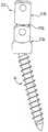
먼저 도 1 및 도 2를 참고하면, 뼈 앵커 어셈블리(10)의 하나의 구현예가 도시되어 있다. 본 구현예에서, 어셈블리(10)는 수용기 부재(12), 뼈 앵커(14), 크라운 부재(16) 및 유지 부재(18)를 포함한다. 어셈블리(10)는 하기에서 보다 상세히 설명된 바와 같이 척추 로드, 핀, 바 또는 다른 임플란트 구조체와 같은 긴 부재(도 7, 20)와 연결 가능하다.Referring first to FIGS. 1 and 2, one embodiment of a
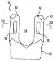
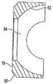
도 3a 내지 3e, 도 7 및 도 8을 참고하고, 본 발명의 하나의 구현예에 의한 수용기 부재 (12)가 도시되어 있다. 수용기 부재(12)는 도시된 구현예에서, 상부 개구부(upper opening portion, 24) 및 하부 개구부 (lower opening portion, 26)를 포함하고 그것을 관통하는 축상 개구부 (axial opening, 22)를 가진다. 개구부 (22)는, 하나의 구현예에서 수용기 부재 (12)의 종축(longitudinalaxis)일 수 있는 종축을 갖는다. 개구부 (22)의 일부분은 챔버 (28)이다. 도시된 구현예에서, 챔버 (28)는 실질적으로 실린더형인 벽들(cylindrically-shaped walls) 또는 면들 (32a, 32b) 및 수용기 부재 (12)의 종축 및 서로에 대해 평행한 거의 평평한 벽들 (34a, 34b)을 구비한다. 벽들(34a, 34b)은 각각 실질적으로 실린더형의 벽부 (36a, 36b)를 가진다. Referring to Figures 3A-3E, 7 and 8, a
개구부 (22)는 수용기 부재 (12)의 선단부 (top portion, 43)에서 모서리가 각지거나 둥근 에지 (rounded edge, 42)에 의해서 일부분으로 둘러싸이고, 수용기 부재 (12)의 저면부(bottom portion, 45)에서 모서리가 깍이거나 또는 둥근 에지 (44)에 의해서 부분적으로 둘러싸인다. 수용기 부재 (12)의 저면부 (45) 내부 또는 그에 인접하여, 그루브 (groove, 46) 및 하부 개구부 (lower opening, 24) 둘레에 결합된 레지 (associated ledge, 48)가 제공될 수 있다. 도시된 구현예에서, 그루브 (46)는 실질적으로 타원형 또는 오발(oval)형이고, 그루브 (46)는 개구부 (22) 주변 둘레에 부분적으로 연장되는 것으로 보여 질 수 있으나, 개구부 (22)의 전체 주면 둘레로 연장된다. 그루브 (46)는 깊이 A (도 7) 및 최대 직경 B(도 3c)를 가진다. 도시된 구현예에서, 그루브(46)의 최대 직경은 수용기 부재(12)의 평평한 면들 (34a, 34b)에 거의 평행하다. 상부 및 하부 개구부 (24, 26)는, 하나 이상의 다른 직경을 갖는 것과 같은, 다양한 변형 또는 추가의 구성을 가질 수 있다.The opening 22 is partly surrounded by a corner edged or
도시된 구현예에서, 수용기 부재 (12)는 사이로 개구부 (22)가 연장하는 한 쌍의 직립형 브랜치 (upright branch, 50, 52)를 포함한다. 또한, 브랜치들 (50, 52)은 개구부 (22)로 통하고, 긴 부재 (20)를 수용하는 크기인 개구부 (22)에 대해 횡으로 실질적으로 U -자형 채널 (54)을 형성한다(도 7). 특정 구현예에서, 암나사산(internal threads, 56)이 채널 (54) 바닥 위 말단벽에 위치할 수 있다. 채널 (54)의 너비와 동일한 직경을 갖는 실린더형의 로드(20)가 가능한 깊숙하게 채널 (56)내에 위치하는 경우, 예컨데, 채널 (54)의 바닥에 접촉하는 경우, 로드 (20)의 상한(upper limit)은 나사산 (56) 아래가 될 것이다. 나사산 (56)의 최대 직경 보다 약간 더 긴 그루브 (57)가 로드 (20)의 상한으로부터 나사산 (56)을 분리한다. 또한, 브랜치들 (50, 52)은 외과의사가 적절한 집게(forceps), 렌치(wrench) 또는 다른 그리핑(gripping) 또는 터닝(turning)도구 (미도시)에 의해 수용기 부재 (12)를 잡을 수 있도록 오목부(indentations) 또는 홀 (58)과 함께 제공될 수 있다. 특정한 하나의 구현예에서 암나사산 (56)은 역경사 나사, 즉 본 명세서에 참조로서 전체적으로 편입되는 미국 특허 제6,296,642호에 개시된 바와 같이, 개구부 (22)로 약간 떨어져서 아래에 로드 플랭크 페이스(load flank faces)를 갖는 암나사산이다. 도시된 구현예에서, 수용기 부재 (12)의 선단부(43) (브랜치들 50, 52 모두 또는 일부를 포함)는 수용기 부재 (12)의 프로파일(profile) 또는 용적을 감소시켜 수용기 부재 (12)의 저면부 (bottom portion, 45) 보다 채널 (54)을 따라 너비가 좁아진다.In the embodiment shown, the
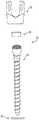
도 4a-4c를 참고하면, 뼈 앵커 (14)의 하나의 구현예가 도시되어 있다. 도시된 구현예에서, 뼈 앵커 (14)는 뼈 스크류인데, 이는 본 명세서에 참조로서 전체적으로 편입되는 미국 특허 제5,885,286호에 개시된 뼈 스크류와 실질적으로 유사하다. 앵커 (14)는 앵커링부 (64) 및 넥(neck) 또는 생크부 (shank portion, 67)에 결합된 헤드부 (66)를 포함한다. 하나의 구현예에서, 앵커 (14)가 스크류일 수 있는데, 앵커링부 (anchorage portion, 64)는 해면 태핑 나사산(cancellous self-tapping thread )일 수 있는 적어도 하나 이상의 나사산(68)을 포함한다. 도시된 구현예에서, 변형된 굽이형(curvate) 및 다른 구조들을 하나 이상 도시된 구현예에서는 두 개를 채용할 수 있으나, 부분적으로 평평한 면 (70)은 헤드부 (66)의 대향면에 제공될 수 있다. 헤드 (66)는 크라운 부재 (16)의 내부에 의한 끌어올림(purchasee)을 개선하기 위해서 일련의 리지들 (ridges, 72)을 포함한다. 헤드 (66)는 러프닝(roughenin), 쇼트피닝 또는 널링(knurling)과 같은, 변형된 또는 추가의 마찰-증가 면구조물(surface configurations)을 가질 수 있다. 또한, 헤드 (66)는 뼈 내부로 앵커링부 (64)를 작동하게 하는 도구(미도시)와 함께 도구-체결 프린트 (tool-engaging print, 74)를 포함할 수 있다. 도구-체결 프린트 (74)는 외부 프린트가 사용될 수 있으나, 도시된 구현예에서는 내부 프린트를 사용하였고, 육각형, 헥사로 베이트 (hexalobate) 또는 다른 토크-전달 형태와 같은 임의의 형태가 사용될 수 있다. 앵커 (14)에 대한 다른 구현예들도 상정할 수 있다. 예들 들어, 앵커 (14)는 스크류보다는 뼈-체결 후크일 수 있다. 상기 구현예에서, 앵커링부 (64)는 나사산 형태의 긴 부재(elongated portion) 보다는, 뼈부분과 같은 체결 조직용(engaging tissue) 후크로 구성될 수 있다.4A-4C, one embodiment of
특정한 하나의 구현예, 헤드 (66)는 수용기 부재 (12) 내의 면들(34a, 34b) 사이의 거리 보다 약간 작은 면들 (70) 사이의 너비를 가진다. 헤드 (66)의 실질적인 구형부의 직경은 적어도 수용기 부재 (12) 내의 면들 (32a, 32b) 사이의 거리 보다 약간 작다. 앵커 (14)의 헤드 (66)의 구현예들은 적어도 수용기 부재 (12)의 하부 개구부 (lower opening, 26) 및 챔버 (28) 내에 끼워지는 크기일 수 있다. 하기에서 보다 상세히 설명한 바와 같이, 앵커 (14)는, 하부 개구부 (26)를 통한 헤드 (66)의 삽입에 하나의 구현예에서 수용기 부재 (12) 내로 삽입되고, 수용기 부재 (12)의 바닥끝 (bottom end, 45)을 통하여 챔버 (28) 내부로 삽입된다.In one particular embodiment, the
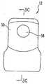
도 5a~5c를 참고하면, 크라운 부재 (16)의 하나의 구현예가 도시되어 있다.본 구현예에서, 크라운 부재(crown member, 16)는 하부면 (lower surface, 82) 및 경사진 에지(beveled edge, 80)와 함께 상단면 (upper surface, 78)을 구비한 약간 직사각형 디스크(oblong disc)이다. 크라운 부재 (16)는 보어 (bore, 84)를 관통하여 연장하는 종방향의 중심축 L을 갖는다. 보어 (bore, 84)는 앵커 (14)의 헤드, 및 특히 도구-체결 프린트 (74)가 그것을 통해서 접근될 수 있는 형태 및 크기가 된다. 평평한 면들 (flat surface, 86, 88)이 크라운 (16)의 대향하는 측면에 제공될 수 있다. 각각의 평평한 면 (86, 88)은, 도시된 구현예에서, 종축 L에 대해 횡방향으로 평평한 면들 (86, 88)로부터 바깥쪽으로 연장하는 작고 둥근 돌출부 (rounded protrusion) 또는 탭(90, 92)을 가진다. 일 구현예에서, 면들 (86, 88)사이에 있는 면들 (93, 94)은 실질적으로 원형(circular)이다. 하부면 (82)은 앵커 (14)의 헤드 (66)를 수용하도록 형성되고, 도시된 구현예에서, 하부면 (82)은 구형의 부분적 형태이다. 다른 구현예에서 크라운 부재 (16)의 하부면 (82)은 하나 이상의 다른 모양을 가질 수 있다. 하부면 (82)은 뼈 앵커 (14)의 헤드 (66)의 결합을 위해 마찰 또는 끌어올림이 강화된 (purchase-enhancing)(예컨데, 러프닝 또는 널링)면구조체와 함께 제공될 수 있다.5A-5C, one embodiment of
크라운 부재 (16)는 수용기 부재 (12)의 챔부 (28) 내로 끼울 수 있는 크기 및 형태로 된다. 크라운 부재(16)가 챔버 (28) 내부에서 종방향으로 활주식으로 이동할 수 있도록 크라운 부재 (16)의 외경은 챔버 (28)의 내경 보다 약간 작다. 특정한 구현예에서, 크라운 부재 (16)는 측면들 86, 88이 벽들 34a, 34b에 인접하고, 벽들 93, 94이 벽들 32a, 32b에 인접하며, 수용기 부재 (12)의 만곡된 벽 부분 (curved wall, 36a, 36b)의 적어도 일부분에 돌출부 (projection, 90, 92)를 끼울 수 있는 크기 및 형태가 된다. 크라운 부재 (16) 및/또는 수용기 부재(12)의 하부 개구부(26)는 크라운 부재 (16)가 하부 개구부(26)를 통해서 챔버 (28)내부로 크라운 부재 (16)가 삽입될 수 있는 크기일 수 있다. 또한, 도시된 구현예에서, 크라운 부재 (16)의 외경은 상부 개구부 (24)의 내경 보다 더 길어서 크라운 부재 (16)는 수용기 부재 (12)의 상부 개구부 (24)로 이동할 수 없다. 도시된 구현예에서, 크라운 부재 (16)의 측면들 (86, 88) 및 벽들 (34a, 34b)의 상한 사이의 간섭 및/또는 돌출부들 (90, 92) 및 벽들(36a, 36b)의 상한 사이의 간섭으로 인해 채널 (56) 내부로 완전하게 이동할 수 없다.The
도 6a-6b를 참고하면, 본 발명의 하나의 구현예인 유지부재 또는 스냅 링(snap ring, 18)이 도시되어 있다. 도시된 구현예에서, 유지 부재 (18)는 갭 (gap, 97)에 의해 분리된 암(arms, 95, 96)을 구비한 클립 또는 실질적으로 C-자형 스프링이다. 유지 부재 (18)는 상단면 (98) 및 바닥면 (100)을 포함한다. 도시된 구현예에서, 유지 부재 (18)는 실질적으로 타원형(elliptical)이거나 또는 오발(oval)형의 외형을 갖고, 또한 실질적으로 원형 애퍼쳐(circular aperture, 108)를 둘러싸는 내부면들 (102, 104, 106)을 포함한다. 다른 구현예에서, 애퍼쳐 (108) 주위를 둘러싸는 단일 또는 다수(multiple)의 내부면이 있을 수 있으며, 이러한 면은 실린더형(cylindrical), 원뿔형(conical), 구형(spherical) 또는 다른 적절한 형태 또는 유지 부재 (18)의 다른 내부형태 및/또는 외부형태일 수 있다. 특정한 구현예에서, 내부면 102은 뼈 앵커 (14)의 헤드 (66)의 반경과 실질적으로 동일한 반경을 가진 구형의 일부분을 형성하고, 내부면 104은 실질적으로 실린더형이고, 내부면 106은 앵커(14)의 경사 위치 결정의 범위를 보다 크게 할 수 있도록 바깥쪽으로 경사지어지면서 실질적으로 원뿔형(conical)일 수 있다. 유지 부재 (18)는 부하 되지 않거나 또는 원래의 외부 L (예를 들어, 타원형 구현예에서 최소 너비 W1 즉, 유지 부재 (18)가 수축 (닫힌 갭) 압력 또는 확장(열린 갭)압력 아닌 상태에서 측정된 너비를 가진다. 또한 도시된 구현예에서 유지 부재의 암들 (95, 96)은 그루브 (46)의 깊이 A 보다는 큰 몸체 너비 W2를 가진다. 또한 유지 부재 (18)의 도시된 구현예는 유지 부재 (18)의 다른 부분 또는 W2 보다 약간 더 좁을 수 있는 회전 가능하거나 또는 힌지 영역 (hinge area, 120)을 추가로 구비한다. 유지 부재 (18)의 너비는, 하나의 구현예에서, 그루브 (46)보다 좁으며 예들 들어, 타원형 유지 부재 (18)의 최대 및 최소 너비는 타원형 그루브 (46)의 최대 및 최소 직경 보다 짧다.6A-6B, a retaining member or
애퍼쳐 (108)의 직경은 유지 부재 (18)가 무부하 상태에 있을 때 뼈 앵커 (14) 의 헤드 (66)의 직경보다 작다. 특정 구현예에서, 유지 부재 (18)는 평평한, 약간 물결 모양(wavy) 또는 파상형(undulating)일 수 있으며, 또는 다른 면에서 특정 구현예에서 실질적으로 평면일 수 있다.The diameter of the
일반적으로 도 1, 2 및 7을 참고하면, 하나의 구현예에서 어셈블리 (10)는 다음과 같이 조립된다. 뼈 앵커 (14), 크라운 부재 (16) 및 유지 부재 (18)는 개별적이거나 또는 실질적으로 한 단계로 하부 개구부 (26)를 통해서 수용기 부재 (12)로 삽입된다. 예로 들면, 크라운 부재 (16)가 먼저 삽입되고, 이어서 유지 부재 (18)와 함께 뼈 앵커 (14)가 삽입될 수 있다. 도시된 구현예에서, 크라운 부재 (16)는 그것의 측면들 (side, 86, 88)이 벽들 34a, 34b에 인접되고, 벽들 93, 94은 벽 32a, 32b에 인접하며, 돌출부들(90,92)은 만곡된 벽 부분들 (36a, 36b)의 적어도 일부분에 끼워지고, 그것의 하부면 (underside, 82)은 수용기 부재 (12)의 하부 개구부 (26)에 닿을 수 있도록 수용기 부재 (12)에 대해 배향되고 삽입될 수 있다. 크라운 부재 (16)는 잠가지기 전에 수용기 부재 (12)의 종축을 따라 활주가능할 수 있다. 앵커 부재 (14)의 헤드 (66)는 앵커 부재(14)의 일부분이 하부 개구부 (26)를 관통하여 연장하도록 크라운 부재 (16)의 인접 위치로 하부 개구부 (26)를 관통하여 삽입될 수 있다. 헤드 (66)의 일부분은 챔버 (28) 내부에 위치될 수 있다.Referring generally to FIGS. 1, 2 and 7, in one embodiment the
유지 부재 (18)는 앵커 부재(14)의 일부분이 유지 부재 (18)의 애퍼쳐 (108)를 통과하도록 그루브 (46) 내부의 적어도 일부분에 위치된다. 유지 부재 (18)는 수용기 부재 (12) 내부로 앵커 (14)를 삽입하기 전에나 삽입하는 중에 또 삽입 한 후에 헤드 (66) 바로 아래에서 앵커 (14) 둘레로 끼워질 수 있다. 특정 구현예에서, 유지 부재 (18)는 앵커 (14) 둘레에 위치되어 애퍼쳐 (108)를 관통하여 앵커 (14)의 앵커링부 (64)를 삽입하고 앵커링부 (64)를 지나 헤드 (66)를 향해 유지 부재 (18)를 이동시킬 수 있다. 다른 구현예에서, 유지 부재 (18)의 갭 (97)은 헤드 (66) 아래의 앵커 (14)의 생크 또는 넥 (67)에 대해 압력을 받을 수 있고, 그에 따라 갭 (97)은 확장되고, 생크 (67)는 갭 (97)을 통과하여 애퍼쳐 (108) 내부로 이동하게 되며, 그 결과 유지 부재 (18)는 원래의 크기 및 형태로 돌아갈 수 있다.The retaining
이와 같은 유지 부재 (18)의 확장은 근본적으로 힌지부 (120) 둘레에 대칭을 이룰 수 있다. 크라운 부재 (16)의 하부면 (82)이 헤드 (66)에 연결되도록 크라운 부재 (16)를 앵커 (14)의 헤드 (66)에 인접하게 위치시키고, 앵커 (14) 및 유지 부재 (18)를 함께, 실질적으로 뼈 앵커 (14)의 삽입과 동시에 끼움으로써, 수용기 부재 (12) 내로 크라운 부재 (16) 및 유지 부재 (18)가 삽입 될 수 있다. 유지 부재 (18)의 삽입으로, 하부 개구부 (lower opening portion, 26) 내부로 향해 위쪽으로 힘이 가해질 것이다.Such expansion of the retaining
외과전문의는, 유지 부재 (18)의 외측 너비가 하부 개구부 (26)를 관통하여 수용기 부재 (12) 내부로 진입할 때까지 수용기 부재 (12)의 면 44 및/또는 면 48에 대하여 유지 부재 (18)에 힘을 가하거나 또는 그의 또는 그녀의 손가락 또는 다른 도구에 의해 갭 (97)을 작게 함으로써 유지 부재를 수축시킬 수 있다. 유지 부재 (18)는 유지 부재 (18)가 적어도 일부분의 그루브 (46)내부로 연장되도록 개구부 (22)를 따라 그루브 (46)내부로 전진한다. 유지 부재 (18)가 타원형인 구현예에서, 그루브 (46)는 타원형이 되고, 수용기 부재 (12)의 종축 둘레에 유지 부재 (18)의 회전은, 그루브 (46)의 벽과 함께 유지 부재 (18)의 일부분의 방해로 인해 제한되거나 방지된다. 유지 부재 (18)의 노치 영역(Notched area, 120)은 암들 (95, 96)을 휘게하여 갭(97)을 폐쇠하는 데 필요한 힘을 감소시킴으로써 유지 부재 (18)의 암들 (95, 96)의 휨을 용이하게 한다. The surgeon may hold the retaining member relative to face 44 and / or face 48 of the
상술한 바와 같이, 하나의 특정 구현예에서, 그루브 (46)의 직경 B는 원래의 또는 부하되지 않은 상태에서의 유지 부재 (18)의 암들 (95, 96)의 외측 너비 W1 보다 작다. 따라서, 유지 부재 (18)가 그루브 (46) 내에 위치하는 경우, 유지 부재 (18)는 그루브 (46)의 벽들에 압력을 가한다. 다른 구현예들에서, 그루브 (46)의 직경 B는 유지 부재 (18)의 원래의 외측 너비 W1와 동일한 크기이거나 또는 그보다 약간 길다. 이러한 경우에 있어서, 유지 부재 (18)의 하부면 (100)은 그루브 (46)의 레지 (48) 위에 위치하고, 그에 의해 그루브 (46) 내에 유지 부재 (18)를 고정시킨다. 유지 부재 (18)는 어셈블리 (10)가 조립되고/거나 잠가지는 경우, 암들 (95, 96)이 그루브 (46)의 측면들과 접촉하도록 확장될 수 있다. 특정한 구현예들에서, 유지 부재 (18)가 그루브 (46) 내에 위치하는 경우, 유지 부재 (18)의 일부분이 개구부 (22) 내로 돌출되도록 그루브 (46)의 깊이 A는 유지 부재 (18)의 너비 W2 보다 작다.As mentioned above, in one particular embodiment, the diameter B of the
유지 부재 (18)가 그루브 (46) 내에 위치하는 경우, 앵커(14) 및 크라운 부재(16)는 수용기 부재 (12)의 개구부 (24) 내에서 유지된다. 크라운 부재(16)는 앵커(14)의 헤드(66)에 의해 지지받고, 헤드(66)는 유지 부재 (18)(예컨대, 본 구현예의 경우 내부면 (102)에 의해)에 의해 지지받는다. 유지 부재 (18)는 수용기 부재 (12)의 그루브 (46) 및/또는 레지 (48)에 의해 고정된다. 따라서, 이러한 구현예에서, 앵커(14) 및 크라운 부재(16)는 유지 부재 (18)가 그루브 (46) 내에 위치하는 경우, 수용기 부재 (12)의 외부에서 유지 부재 (18)를 관통하지 않는다. 크라운 부재(16) 및 앵커(14)의 헤드(66)는 수용기 부재 (12)의 개구부 (22) 및/또는 챔버 (28) 내에 위치되고, 잠그기 이전에 수용기 부재 (12)의 종축을 따라 실질적으로 활주 가능하다. 앵커(14)는 잠그기 이전에 크라운 부재(16) 및 수용기 부재 (12)에 대해 하나의 평면 내에서 선회 가능하지만, 도시된 구현예에서, 앵커(14) 및 크라운 부재(16) 및/또는 수용기 부재 (12)의 대응하는 면들 사이의 관계로 인해 실질적으로는 수용기 부재 (12)의 종축 둘레로 선회나 회전이 제한된다.When the retaining
도시된 구현예에서, 어셈블리 (10)의 사용이 척추 수술과 관련하여 설명되었으나, 어셈블리 (10)가 다른 수술 부위 또는 조직과 관련하여서도 사용될 수 있음을 이해해야 할 것이다.In the illustrated embodiment, the use of
어셈블리 (10)는 척추 또는 다른 조직의 기형 (예컨대, 추골의 전이 및 회전 중 하나 또는 둘 다이거나 또는 다른 관상 및 시상 평면들 중 하나 또는 둘 다의 이동이 요구될 수 있는 척추측만 굽이(scoliotic curvature)), 변성 또는 외상의 교정과 같은 다양한 수술 분야에서 사용될 수 있다.
어셈블리 (10)는 외과 수술에 사용되기 이전에 조립될 수 있으나, 이러한 조립은 외과 의사, 보조자 또는 어떠한 경우에는 다른 사람에 의해 수행될 수 있다. 앵커 (14)는 수술 부위에 제공되고 추골에 연결된다(미도시). 구현예에서, 앵커 (14)는 스크류이고, 추골 내로, 예들 들어, 준비된(예컨대, 천공(drilled) 및 태핑된(tapped))홀 내부로 나사산 형태로 끼워진다. 다른 구현예에서, 예들 들어 앵커 (14)가 뼈 후크(hook)인 경우는, 뼈 내로 나사산 형태로 끼움 및/또는 뼈 내에 홀의 천공이 필요하지 않을 것이다.
앵커링부 (64)는 추골, 및 적절한 터닝 도구(turning tool), 예컨대 크라운 부재(16)의 홀 (84)을 관통하여 앵커(14)의 도구-체결 프린트 (74)와 함께 사용가능한 도구에 연결되고, 뼈 내로 앵커(14)를 나사산 형태로 끼우는데 사용될 수 있다. 앵커(14)가 추골에 원하는 깊이로 삽입되거나 위치되는 경우, 수용기 부재 (12)는 개구부 (22)가 앵커(14)에 의해 원하는 각을 형성하도록 위치될 수 있다.The anchoring
도시된 구현예에서, 앵커(14) 및 개구부 (22) 사이의 각 θ는 각 방향에서 30도까지 가질 수 있다. 개구부 (22)에 대한 앵커 (14)의 최대 각은 여러 방법으로 변화될 수 있으며, 예를 들어, 앵커(14)의 헤드(66) 아래의 생크 또는 다른 부분을 박형화하거나 수용기 부재 (12)의 종축에 대한 면 (44)의 스티퍼 각(steeper angle)의 제공 및/또는 수용기 부재 (12)의 바닥 말단 (24)에 가능한 인접하게 그루브 (46)를 배치하는 방법이 있다.In the illustrated embodiment, the angle θ between the
외과 의사는 채널 (54) 및 긴 부재 (20)를 평행하게 배열할 수 있고/거나, 추골(들)에 원하는 지지력을 제공하고 수용기 부재 (12) 내에서 용이하게 감소가 가능하도록 긴 부재를 구부릴 수 있다. 긴 부재 (20) 및 채널 (54)이 정렬될 때 또는 그 이전에 어셈블리 (10)는 실질적으로 하나의 평면, 예를 들어 시상 평면(sagittal plane) 내에서, 앵커 (14)에 대해 수용기 부재 (12)를 이동시킨다. 상술한 바와 같이, 챔버 (28) 내부의 면들 (34a, 34b), 크라운 부재 (16)의 외부 측면들 (86, 88) 및 앵커 (14)의 헤드 (66) 상의 면들 (70)은, 앵커 (14)의 면들 (70)에 평행하고 앵커 (14)의 종축을 포함하는 평면 이외에 수용기 부재 (12)에 대해 앵커 (14)의 회전을 실질적으로 방해하고 제한할 것이다.The surgeon may arrange the
상술한 바와 같이, 수용기 부재 (12)는 앵커(14)에 대해 각을 가질 수 있다. 긴 부재 (20)는 실린더형, 평평하거나 또는 다른 형태의 정형외과용 로드, 핀, 바(bar), 커넥터 또는 다른 임플란트 형태일 수 있으며, 어셈블리 (10)와 결합된다.As mentioned above, the
긴 부재 (20)는 수용기 부재 (12)의 채널 (54) 내에 크라운 부재 (16)의 상단면 (78)에 인접하게 위치된다. 압축 부재(compression member, 110)는 압축 부재 (110)가 나사산 (56) 내로 끼워지고 긴 부재 (20)에 체결됨으로써 수용기 부재 (12)에 연결된다. 하나의 구현예에서, 토크를 가하기 위한 프린트 (114) 및 수나사산(112)을 갖는 세트 스크류 또는 플러그이고, 특정 구현예에서는, 본 명세서에 참조로서 전체적으로 편입되는 셔먼 외, 미국 특허 제5,885,286호 또는 고르네이 외, 미국 특허 제6,193,719호에 기재된 바와 같이, 브레이크-오프셋 스크류(break-offset screw)일 수 있다.The
다른 구현예에서, 나사산(112)은 본 명세서에 참조로서 전체적으로 편입되는 모리슨 외, 미국 특허 제 6,296,642호에 기재된 바와 같이, 역각 나사산일 수 있는데, 이는 상술한 바와 같이, 수용기 부재 (12)의 나사산 (56)의 역각 구현예ddkh 호환 가능하다. 수용기 부재 (12)가 수나사산 형태로 끼워지는 구현예에서, 압축 부재 (110)는 암나사산 너트가 될 수 있다.In another embodiment, the
압축 부재 (110)가 조여짐에 따라, 긴 부재 (20)는 크라운 부재 (16)에 대해 아래 방향으로 힘을 받고 앵커 (14)의 헤드 (66)에 대해 크라운 부재(16)를 밀게 된다. 그러므로 헤드 (66)는 크라운 부재 (16) 및 유지 부재 (18) 사이로 클램핑된다. 구현예에서, 헤드 (66)는 리지들 (72)을 포함하고, 리지들 (72)은 크라운 부재 (16)의 하부면 (82)으로 압력을 받는다. 헤드 (66)는 유지 부재 (18)에 대해 그루브 (46)내로 압력을 받는다. 이러한 방식으로, 앵커 (14)는 원하는 각도 위치에서 나머지 어셈블리 (10) 및 긴 부재 (20)에 대해 잠기게 된다.As the
상술한 구현예 및 다른 구현예에서 구성요소의 재료는 스테인레스 스틸, 코발트-크롬 합금, 티타늄 또는 그 외 단단한 생체적합성 재료일 수 있다.In the above and other embodiments, the material of the component may be stainless steel, cobalt-chromium alloy, titanium or other hard biocompatible material.
특정 구현예에서, 크라운 부재 (16)는 앵커 (14)의 헤드 (66)의 리지들 (72)에 사용하는 재료보다 더 부드러운 재료로 만들어질 수 있다. 이러한 구성은 리지들 (72) 및 크라운 부재(16) 사이로 보다 분명하게 끌어올림(purchase)을 제공하에 따라, 어셈블리 (10)를 잠그는 동안 크라운 부재 (16)의 내부면 (82)으로 리지들 (72)의 관통을 더 용이하게 한다. 다른 구현예에서, 크라운 부재 (16)는 긴 부재 (20)에 사용하는 재료보다 더 부드러운 재료로 만들어질 수 있다. 이러한 구성은 어셈블리 (10)를 잠그는 동안 크라운 부재 (16)의 상단면 (78)이 긴 부재 (20)의 것과 유사하거나 비슷한 형태로 변형되도록 한다. 다른 구현예에서, 긴 부재 (20)는 크라운 부재 (16)의 상단면 (78)이 긴 부재 (20)에 맞물리고, 그것을 관통하거나 또는 변형시키도록 긴 부재 (20)는 크라운 부재 (16)보다 더 부드러울 수 있다.In certain embodiments, the
일반적으로 도 9 내지 13을 참고하면, 수용기 부재 12의 구현예와 많은 부분이 유사하거나 동일한 수용기 부재 212의 또 다른 구현예들이 도시되어 있다. 수용기 부재 212의 특징들은 접두사 200이 부가되어 동일한 부호를 갖는 수용기 부재 12의 것들과 유사하거나 동일하다.Referring generally to FIGS. 9-13, further embodiments of
도시된 구현예에서, 수용기 부재 (212)는, 박형부 (thinned section, 212c)에 의해서 분리된 하부 (212a) 및 상부 (212b)를 가진다. 하부 (212a)는 종축, 일 구현예에서는 수용기 부재 212의 종축과 함께 그것을 관통하는 개구부 (222)를 갖는 수용기 부재 12와 실질적으로 동일하다. 도시된 구현예에서, 개구부 (222)의 일부분은 실질적으로 실린더형 벽들 또는 면들(면 232a 및 대향면) 및 수용기 부재 (212)의 종축에 대해 그리고 서로 평행한 일반적으로 평평한 벽들 또는 면들 234a 및 234b을 갖는 챔버 (228)이다. 벽들 (234a, 234b)은 각각 실질적으로 실린더형 벽부 (236a, 236b)를 구비한다. 모서리가 깎이거나 또는 둥근 에지 242는 하부 (212a)의 꼭대기 및/또는 상부 (212b)의 꼭대기에 또는 이에 인접하게 제공되고, 모서리가 깍이거나 또는 둥근 에지 244는 하부 (212a)의 저면부 (245)에 제공될 수 있다. 또한, 그루브 (246) 및 결합된 레지 (248)도 제공될 수 있다. 그루브 246은 상술한 바와 같이, 형태 및 부피(dimension)가 그루브(46)와 동일하게 구성된다.In the illustrated embodiment, the
도시된 구현예에서, 수용기 부재 (212)는 개구부 (222)가 연장하는 사이로 한 쌍의 직립형(upright) 브랜치들(branch, 250, 252)을 포함한다. 또한, 브랜치들 (250, 252)은 개구부 (222)와 연결되고, 긴 부재를 수용하기 위한 크기이고, 개구부 (222)에 횡방향으로 실질적으로 U-형 채널 (245)로 정의된다. 각 브랜치들 (250,252)의 일부분은 수용기 부재 (212)의 하부 (212a)에 적어도 일부분을 형성하고, 각 브랜치들(250, 252)의 일부분은 수용기 부재 (212)의 상부 (212b) 적어도 일부분을 형성한다. 또한, 브랜치들 (250, 252)은 개구부 (222)로 통하고, 긴 부재를 수용하는 크기인 개구부 (222)에 대해 횡으로 실질적으로 U -자형 채널 (254)을 형성한다. 각 브랜치들 (250,252)의 일부분은 수용기 부재 (212)의 하부 (212a)의 적어도 일부분을 형성하고, 각 브랜치들(250, 252)의 일부분은 수용기 부재 (212)의 상부 (212b)의 적어도 일부분을 형성한다. 특정 구현예에서, 암나사산 (256)은 브랜치들 (250, 252) 내에 실질적으로 상부 (212b)의 전체 길이를 관통하여 하부 (212a) 내부로 형성된다. 나사산 (256)은 채널 (254)의 바닥 위의 말단 벽에 제공될 수도 있다. 채널 (254)의 너비와 동일한 직경의 실린더형 로드 (cylindrical rod, 220)가 가능한 한 깊게 채널 (254)에 위치되는 경우, 즉, 채널 (254)의 바닥과 접촉한다면, 로드 (220)의 상한(upper limit)은 나사산 (256) 아래가 될 것이다. 나사산 (256)의 최대 직경 보다 약간 더 긴 그루브 (257)가 로드 (220)의 상한으로부터 나사산 (256)을 분리한다. 또한, 브랜치들 (250, 252)은 외과의사가 적절한 집게(forceps), 렌치(wrench) 또는 다른 그리핑(gripping) 또는 터닝(turning)도구 (미도시)에 의해 수용기 부재 (212)(212a, 212b부의 둘 또는 하나)를 잡을 수 있도록 오목부(indentations) 또는 홀 (258)과 함께 제공될 수 있다. 특정한 하나의 구현예에서, 나사산 (256)은 역경사 나사, 즉 본 명세서에 참조로서 전체적으로 편입되는 미국 특허 제6,296,642호에 개시된 바와 같이, 개구부 (222)로 약간 떨어져서 아래에 로드 플랭크 페이스(load flank faces)를 갖는 나사산이다.In the illustrated embodiment, the
도시된 구현예에서, 수용기 부재 (212)의 상부 (212b)는 상술한 바와 같이, 암나사산 (256) 및 오목부(indentations, 258)를 구비한 브랜치들(250, 252)의 일부분을 포함한다. 나사산 (256)은 섹션 (212c) 주위 또는 섹션부 (212c)를 가능한 제외한 채로 상부 (212b)에서 하부 (212a)까지 근본적으로 연속되게 구성될 수 있다. 이러한 구현예에서, 압축 부재(예컨대, 상기에서 압축 부재 (110)로 도시된)는 상부 (212b) 내로 삽입되어, 하부 (212a)의 아래로 이동될 수 있다. 예를 들어, 상부 (212b) 내에 끼워진 세트 스크류는 개구부 (222)를 따라 하부 (212a) 내로 나사산 형태로 끼워질 수 있다. 다른 구현예에서 부분 212a 및 212b가 분리되어 형성되어 서로 결합하거나 또는 다른 형태를 형성될 수 있지만, 도시된 구현예에서, 상부 (212b)는 하부 (212a)와 함께 일체로 형성된다.In the illustrated embodiment, the
또한, 도시된 구현예는 하부 (212a) 보다 약간 짧거나 거의 동일한 높이일 수 있는 상부 (212b)를 도시한다. 수용기 부재 (212)의 다른 구현예는 하부 (212a) 보다 짧거나 절반 정도의 높이를 갖는 상부 (212b)를 포함하거나 또는 하부 (212a) 보다 실질적으로 긴 높이를 갖는 상부(212b)를 포함할 수 있다.In addition, the illustrated embodiment shows the top 212b, which may be slightly shorter or about the same height as the bottom 212a. Another embodiment of the
상술한 바와 같이, 도시된 구현예에서는 박형섹션 (212c)이 상부 (212b) 및 하부 (212a)를 분리한다. 섹션 (212c)의 이러한 구현예는, 스코어링 라인(scoring lines) 또는 다른 프랙쳐(fracture)를 포함하거나 또는 프랙쳐 가능한 형태를 포함하는, 외부 오목부 또는 그루브 (260)를 포함한다. 또한 도시된 구현예에서, 내부 오목부(indentation, 261)는, 나사산 (256)을 가로막고 나사산 (256)의 최대 직경 보다 약간 더 깊게 제공될 수 있다. 섹션 (212c)은 브랜치들 (250, 252)의 총 두께 보다는 적어도 조금 더 작은 두께를 가지며, 특정한 구현예에서 두께는 브랜치에 나사산 트라프(trough)에서 외부 브랜치까지 측정된 브랜치들(250, 252)의 두께 보다 적어도 조금 더 작다.As described above, in the illustrated embodiment, the
수용기 부재(212)는 상기 도시된 구현예에 유사하거나 또는 동일한 것처럼 뼈 앵커 어셈블리를 만들기 위해, 앵커 부재(14), 크라운 부재 (16) 및 유지 부재 (18)의 상기 도시된 구현예처럼 실질적으로 조립될 수 있다. 추가로, 수용기 부재 (212)로 만든 어셈블리는 상기에 도시된 바와 같이 수술 시에 사용이 가능하다. 외과전문의가 수용기 부재(212) 내로 긴 부재(220)를 삽입할 경우에, 외과전문의는 그것을 구부릴 필요가 없고 수용기 채널의 하부 말단으로 그것을 삽입하기 위해 특정 수축 도구를 사용할 필요도 없다. 좀 더 정확히 말하면, 외과전문의는 수용기 부재(212)의 상부(212b)에서 채널(254) 내로 긴 부재(220)의 일부분을 배치한다. 세트 스크류 또는 다른 압축 부재(예를 들어, 상기 설명된 압축 부재(110))는 긴 부재(220) 위에서 개구부(222) 내로 삽입된다.The
압축 부재가 세트 스크류인 구현예에서, 상기 세트 스크류는 나사산(256) 내에 나사산 형태로 끼워져 추가로 채널(254)의 아래로 긴 부재(220)를 누른다. 이러한 방법으로, 실질적으로 어셈블리(10)에 대해 상기에서 기술한 바와 같이, 긴 부재(220)는 상부(212)를 통하는 모든 통로, 하부 부재(212a) 내부로, 챔버(228) 내에 크라운 부재 및/또는 앵커 부재에 대항하도록 힘을 가하게 된다.In embodiments where the compression member is a set screw, the set screw is threaded into
압축 부재가 외과전문의가 만족하도록 긴 부재(220)를 조여서 어셈블리를 잠글 경우, 상부(212b)는 절단되거나 잘릴 수 있으며 또는 이와 달리 하부(212a)로부터 착탈될 수 있다. 본 발명의 하나의 양상에서, 그리핑(gripping) 또는 터닝(turning)용 도구는 상부(212b) 및 하부(212b) 중 하나 또는 모두를 연결할 수 있고, 토크는 개별적으로 부분을 자르거나 또는 휘어감도록 적용될 수 있다. 본 발명의 다른 양상에서, 각각 날카로운 자(sharp jaws)를 가진 도구는 상부(212b)를 절단하기 위해 외부 그루브(260)에 적용될 수 있다. 하부(212b)로부터 상부(212a)를 물리적으로 분리하기 위해 다른 방법이 사용될 수 있다. 분리되면, 상부(212b)는 수술 부위로부터 떨어지고 버려진다.When the compression member locks the assembly by tightening the
상기 설명에서 확인할 수 있는 바와 같이, 특정 구현예들은 하나의 평면, 예를 들어, 시상평면, 횡단평면(transverse plane), 시상평면 및 횡단평면 사이의 평면 또는 다른 평면에서 실질적으로 서로에 대해 회전가능한 헤드부 및 앵커부를 구비하는 뼈 앵커를 제공한다. 이러한 구현예들은 다양한 내부 구성에 의해서 다른 평면에서 서로에 대한 선회에 대하여 필수적으로 잠가질 수 있다.As can be seen from the description above, certain embodiments are rotatable with respect to one another substantially in one plane, for example, a sagittal plane, a transverse plane, a plane between a sagittal plane and a transverse plane or another plane. A bone anchor having a head portion and an anchor portion is provided. These embodiments can be essentially locked against turning against each other in different planes by various internal configurations.
상기에서 설명한 바와 같이, 도시된 구현예들(및 그 밖의 경우)은 다양한 외과적 시술에 사용될 수 있다. 그러한 시술의 또 다른 예로는 척추 외상(spinal trauma) 또는 퇴행성(degenerative condition)이 존재할 경우에의 적용이 고려되며, 하나 이상의 어셈블리들(10)은 상기 수용기 부재(12, 212) 및 상기 앵커(14)가 실질적으로 하나의 평면에서 서로에 대해 선회가능한 상태에서 사용된다. 이러한 경우, 어셈블리(10)는 기술된 외과적 부위 또는 외과전문의가 의도하는 다른 부위에 도입될 수 있고 추골 조직에 삽입될 수 있다. 많은 외과 시술에서, 외과전문의는 수용기 부재(12, 212) 및 앵커(14)가 서로에 대해 선회할 수 있는 평면이 척주의 적어도 일부분에 실질적으로 시상, 실질적으로 수직, 및/또는 실질적으로 평행하도록 어셈블리(10)를 설치하는 것을 선호할 수 있다. 물론, 외과전문의는 그가 의도하는 대로 어셈블리(10)를 장착할 수 있는 것으로 이해되어야 한다. 예를 들어, 수용기 부재(12, 212) 및 앵커(14)가 서로에 대해 선회할 수 있는 평면이 비-시상적으로 장착된다.As described above, the illustrated embodiments (and elsewhere) can be used for various surgical procedures. Another example of such a procedure contemplates application in the presence of spinal trauma or degenerative conditions, in which one or
어셈블리(10)가 추골 내로 삽입되면, 어셈블리(10)는 추골에 대해 최종위치의 1/4 턴(90도)에 못미치는 위치로 나사산 형태로 끼워질 수 있다. 예를 들어, 추골에 대해 어셈블리(10)의 최종 위치는 채널(54, 254)이 실질적으로 시상으로 면하도록 되거나, 또는 수용기 부재(12, 212)가 실질적으로 시상평면에서 회전하고, 어셈블리(10)가 상기 최종 위치(예를 들어, 실질적으로 측면)의 등(dorsal)의 1/4 턴 되도록 추골 내로 나사산 형태로 끼워지는 상태일 수 있다. 이러한 최종-이전(pre-final) 상태에서, 앵커(14)에 대한 수용기 부재(12, 212)의 시상평면에서의 이동은 실질적으로 제한되거나 또는 방해된다.When
초점이 되는 외상 및/또는 퇴행성에 유용한 교정 기술, 즉, 추골 또는 추골 분절들의 압축, 신연(distraction), 회전 및/또는 다른 조정과 같은 교정 기술은 그러한 최종-이전 상태에서 추골 내의 어셈블리(10)(또는 복합 어셈블리들(10), 사용될 경우) 또는 뼈들에 적용될 수 있다. 예를 들어, 압축이 필요할 경우, 외과전문의는 그의 손가락 또는 도구(미도시)를 사용하여 어셈블리들(10)을 압착할 수 있다. 본 발명의 또 다른 양상에서, 신연이 필요할 경우, 외과전문의는 그의 손가락 또는 도구(미도시)로 어셈블리(10)를 당기거나 밀어서 분해할 수 있다. 두 가지 경우에 있어, 어셈블리(10)의 측면에 가해진 힘은 어셈블리들(10) 간의 상대적 위치의 변화를 야기할 것이고, 어셈블리(10')의 수용기 부재(12, 212)가 그들 각각의 앵커들(14)에 대해 실질적으로 선회하지 않게 할 것이다. 인체 내의 장치는 추골 사이의 목적하는 공간을 유지하기 위해 인접한 추골 사이로 이식될 수 있다. 그러한 추골에 대한 작동들, 하나 이상의 어셈블리(10), 또는 다른 정형 외과용 요소들은 특정 환자의 상태에 의해 결정되는 대로 및/또는 외과전문의가 의도하는 대로 제조될 수 있다.Correction techniques useful for traumatic and / or degenerative focus, i.e., correction techniques such as compression, distraction, rotation and / or other adjustment of the vertebral or vertebral segments, may cause the
일단 추골의 임의의 조정이 수행되고, 척추 또는 그의 일부분이 외과전문의가 의도한 상태라면, 어셈블리(들)(10)는 그들 각각의 추골 내로 최종 1/4 턴 회전된 상태가 될 수 있다. 그런 뒤, 어셈블리(들)(10)는 외과전문의에 의하여 의도된 추골에 대한 최종 위치에서 정지된다. 척추 로드, 바 또는 다른 종류와 같은 긴 부재는 각각의 어셈블리(10)의 수용기 부재(12, 212)의 채널(54, 254) 내로 삽입되어 실질적으로 상기 설명한 바와 같이 고정될 수 있다. 상기 방법들 및 어셈블리들의 구현예들을 사용하면, 외과전문의는 필요할 경우 압축 및 신연의 방향으로 본질적으로 고정된 나사를 장치 내에 구비하고, 로드 또는 다른 긴 부재가 장치 내부에 설치될 경우에 선회식, 각지게 조절가능한 스크류를 최종 위치에 구비한다. 본 발명에서 두 개 이상의 뼈 앵커 어셈블리들을 사용하는 것으로 설명된 방법들의 구현예들은, 예를 들어, 상기 뼈 앵커 어셈블리 각각에 대한 어셈블리(10)를 사용할 수 있거나, 또는 하나 이상의 어셈블리(10)에 따른 다른 종류의 앵커들을 사용할 수 있다.Once any adjustment of the vertebrae is performed and the spine or a portion thereof is intended by the surgeon, the assembly (s) 10 may be in the final quarter turn of rotation into their respective vertebrae. The assembly (s) 10 then stops at the final position relative to the spine intended by the surgeon. Elongated members, such as spinal rods, bars or other types, may be inserted into
비록 상기 구현예들을 도면 및 상기의 설명에서 상세하게 기술하고 설명하였으나, 이는 단지 예시적인 것으로 고려되어야 하며, 발명의 특성을 제한하는 것으로 해석되지 않아야 하며, 단지 특정 구현예들이 도시되고 기술되었으며, 본 발명의 본질 내에서 발생하는 모든 변화 및 변경은 보호되는 것으로 의도되는 것임이 이해되어야 한다.Although the embodiments have been described and described in detail in the drawings and above description, they should be considered as illustrative only and should not be construed as limiting the nature of the invention, only specific embodiments have been shown and described, and It is to be understood that all changes and modifications occurring within the spirit of the invention are intended to be protected.
예를 들어, 어셈블리(10)에 대해 기술된 구현예는 채널(54)을 관통하는 축을 포함하는 평면에서 앵커 부재(14)의 선회를 가능하게 하는 수용기 부재(12)의 면들(34a, 34b)의 배열을 보여준다. 즉, 어셈블리(10)에 대해 기술된 구현예는 채널(54) 아래의 실질적으로 실린더-형상의 면들(32a, 32b) 및 브랜치들(50, 52) 아래의 일반적으로 평평한 면들(34a, 34b)을 도시하였다. 면들(34a, 34b)은 앵커 부재(14)가 선회하는 평면이 채널(54) 및 그로부터 연장된 부재(20)에 경사지거나 수직이 되도록 수용기 부재(12) 내에서 다른 곳에 배치될 수 있다. 도 14-16에 도시된 구현예에서, 앵커 부재(14)는 수용기 부재(12') 내에서 수용기 부재(12')의 종축에 대해 각 θ를 이루면서 채널(54')에 실질적으로 수직으로, 즉, 횡단평면으로, 선회한다. 상기 구현예에서, 수용기 부재(12')의 내부 구조는 도 1-3e 및 8-13에 도시된 바와 같이 수용기 부재(12, 212)의 내부 구조로부터 약 90 도 정도 회전한다. 예를 들어, 실질적으로 실린더-형상의 면들은 채널(54') 아래에 있고 일반적으로 평평한 면들은 브랜치들(50', 52') 아래에 있다. 본 발명의 다른 양상에서, 이러한 어셈블리(10')의 구현예는 앞서 설명하고 도시한 어셈블리(10) 및 일부분과 유사하거나 동일하다. 만일 타원형 그루브(그루브(46)에 유사한) 및 유지 부재 (부재(18)과 유사)가 어셈블리(10')에서 사용될 경우, 상기 그루브의 최대 지름은 수용기 부재(12') 내에서 일반적으로 평평한 면들 중 상기 평면에 실질적으로 평행하도록 재배치될 수 있으며, 이는 수용기 부재(12)의 면들(34a, 34b)에 비교될 수 있다.For example, the implementation described with respect to
어셈블리(10')는 어셈블리(10)에 대하여 상기 설명한 바와 같이 실질적으로 조립되고 사용된다. 어셈블리(10')는 어셈블리(10)를 "최종-이전" 위치로 삽입하는 것에 대해 상기에서 설명한 바와 같이, 특정 정형외과적 교정 기술용으로 제공할 수 있다. 일단 어셈블리(10')가 원하는 대로 추골에 삽입되면, 실질적으로 앵커(14)에 대한 수용기 부재(12')의 로드(예를 들어, 시상평면)를 따른 평면 내에서의 이동은 실질적으로 제한되거나 또는 방해된다. 초점이 되는 외상 및/또는 퇴행성에 유용한 교정 기술, 즉, 추골 또는 추골 분절들의 압축, 신연, 회전 및/또는 다른 조정과 같은 교정 기술은 어셈블리(10')(또한, 만일 사용된다면, 복합 어셈블리들(10')) 또는 뼈들에 적용될 수 있다. 예를 들어, 압축이 필요할 경우, 외과전문의는 그의 손가락 또는 도구(미도시)를 사용하여 어셈블리들(10')을 압착할 수 있다. 본 발명의 또 다른 양상에서, 신연이 필요할 경우, 외과전문의는 그의 손가락 또는 도구(미도시)로 어셈블리(10')를 당기거나 밀어서 분해할 수 있다. 두 가지 경우에 있어, 어셈블리(10')의 측면에 가해진 힘은 어셈블리들(10') 간의 상대적 위치의 변화를 야기할 것이고, 어셈블리(10')의 수용기 부재(12')가 그들 각각의 앵커들(14)에 대해 실질적으로 선회하지 않게 할 것이다. 인체 내의 장치는 추골 사이의 목적하는 공간을 유지하기 위해 인접한 추골 사이로 이식될 수 있다. 상기에서 기재한 바와 같이, 추골에 대한 작동들, 하나 이상의 어셈블리(10'), 또는 다른 정형 외과용 요소들은 특정 환자의 상태에 의해 결정되는 대로 및/또는 외과전문의가 의도하는 대로 제조될 수 있다.
본 발명의 또 다른 양상에서, 어셈블리(10)의 구현예들은 크라운 부재(16) 없이 만들어질 수 있다. 이러한 구현예들에서는, 앵커(14)의 헤드(66)의 면들(70)이 수용기 부재(12)의 면들(34a, 34b)에 인접할 것이고, 면들(34a, 34b)과 면들(70) 사이의 관계는 실질적으로 하나의 평면에 대해 수용기 부재(12)에 대한 앵커(14)의 선회를 제한할 것이다. 또한, 긴 부재(20)는 이러한 구현예들에서 헤드(66)에 대해 직접적으로 압력을 가할 수도 있다.In another aspect of the invention, embodiments of
상기에서 기재한 바와 같이, 상기 어셈블리의 몇몇의 구현예들은 실질적으로 한 평면에서 조직 또는 그러한 조직 내의 앵커에 대해 일반적으로 선회 가능한 수용기 부재를 구비한다. 이러한 평면은 상기 어셈블리의 구성 및/또는 조직(예를 들어, 추골 또는 다른 뼈 조직)에 관한 상기 어셈블리의 배치에 의해서 결정될 수 있다. 상기 어셈블리의 수용기 부재 내의 면들, 크라운 부재 상의 면들, 및/또는 다른 형태들은 앵커 및 수용기 부재가 상기 수용기 부재의 채널에 실질적으로 평행하거나, 상기 채널에 실질적으로 수직이거나, 또는 상기 채널에 일정 경사각을 가진 평면 내에서 서로에 대해 선회 가능하도록 정렬될 수 있다. 상기 어셈블리는 상기 수용기 부재가 무한한 평면들 중 하나에서 실질적으로 선회하도록, 예를 들어, 원하는 평면에서 실질적으로 선회를 유발하는 각으로 뼈 내로 상기 어셈블리의 스크류형 앵커를 회전함으로써, 조직에 연결될 수 있다. 인체에 대하여, 이와 같은 평면은 실질적으로 시상, 실질적으로 횡단, 또는 시상 및 횡단 사이의 평면일 수 있으며, 또는 장착되는 인체에 의해 가능하며 외과전문의에 의해서 의도된 임의의 다른 평면일 수 있다. 시상 및 횡단평면 사이의 평면에서, 조직에 연결된 앵커에 대하여 선회 가능한 상기 수용기 부재를 구비한 어셈블리는 다른 수술 상황 또는 시술들 중 하부 추골, 엉치(sacral) 및/또는 엉덩이 부위(iliac area)에서의 임플란트 구조체에 유용하게 이용될 수 있다.As described above, some embodiments of the assembly include a receiver member that is generally pivotable about a tissue or anchor within such tissue in substantially one plane. This plane may be determined by the configuration of the assembly and / or the placement of the assembly relative to the tissue (eg, the vertebral or other bone tissue). The faces in the receiver member of the assembly, the faces on the crown member, and / or other shapes may be such that the anchor and receiver member are substantially parallel to the channel of the receiver member, substantially perpendicular to the channel, or have a certain tilt angle to the channel. It can be arranged to be pivotable with respect to each other in the plane of the excitation. The assembly can be connected to tissue such that the receiver member pivots substantially in one of the infinite planes, for example, by rotating the screwed anchor of the assembly into the bone at an angle that causes substantially pivoting in the desired plane. . With respect to the human body, such a plane can be substantially sagittal, substantially transverse, or a plane between sagittal and transverse, or any other plane possible by the human body to be mounted and intended by the surgeon. In the plane between the sagittal and transverse planes, the assembly with the receiver member pivotable about an anchor connected to the tissue may be used in the lower vertebrae, sacral and / or hip areas of other surgical situations or procedures. It can be usefully used in the implant structure.
도 1은 조절식 뼈 앵커 어셈블리의 하나의 구현예의 측면도이다.1 is a side view of one embodiment of an adjustable bone anchor assembly.
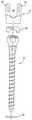
도 2는 도 1에 도시한 구현예의 분해 조립도이다.2 is an exploded view of the embodiment shown in FIG. 1.
도 3a는 도 2에 도시한 수용기 부재의 하나의 구현예의 측면도이다.3A is a side view of one embodiment of the receiver member shown in FIG. 2.
도 3b는 도 3a에 도시한 수용기 부재의 구현예에 대한 정면도이다.3B is a front view of an embodiment of the receiver member shown in FIG. 3A.
도 3c는 도 3a의 선 3c-3c를 따라 자르고, 화살표 방향으로 도시한, 도 3a에 도시된 수용기 부재의 구현예의 단면도이다.FIG. 3C is a cross-sectional view of the embodiment of the receiver member shown in FIG. 3A, cut along
도 3d는 도 3b의 선 3d-3d를 따라 자르고, 화살표 방향으로 도시한, 도 3b에 도시된 수용기 부재의 구현예의 단면도이다.3D is a cross-sectional view of the embodiment of the receiver member shown in FIG. 3B, cut along the lines 3d-3d of FIG. 3B and shown in the direction of the arrow.
도 3e는 도 3c의 선 3e-3e를 따라 자르고, 화살표 방향으로 도시한, 도 3c에 도시된 수용기 부재의 구현예의 단면도이다.3E is a cross-sectional view of the embodiment of the receiver member shown in FIG. 3C, cut along the
도 4a는 도 2에 도시한 구현예에서 뼈 앵커의 하나의 구현예의 측면도이다.4A is a side view of one embodiment of a bone anchor in the embodiment shown in FIG. 2.
도 4b는 도 4a의 선 4b-4b를 따라 자르고, 화살표 방향으로 도시한, 도 4a에 도시된 뼈 앵커의 구현예의 단면도이다.4B is a cross-sectional view of the embodiment of the bone anchor shown in FIG. 4A, cut along the lines 4b-4b of FIG. 4A and shown in the direction of the arrow.
도 4c는 도 4a에 도시한 뼈 앵커의 헤드의 하나의 구현예의 확대도이다.4C is an enlarged view of one embodiment of the head of the bone anchor shown in FIG. 4A.
도 5a는 도 2에 도시한 구현예에서 사용한 크라운 부재의 하나의 구현예의 평면도이다.FIG. 5A is a plan view of one embodiment of a crown member used in the embodiment shown in FIG. 2. FIG.
도 5b는 도 5a의 선 5b-5b를 따라 자르고, 화살표 방향으로 도시한, 도 5a에 도시된 크라운 부재의 구현예의 단면도이다.FIG. 5B is a cross-sectional view of the embodiment of the crown member shown in FIG. 5A, cut along the line 5b-5b of FIG. 5A and shown in the direction of the arrow.
도 5c는 5a에 도시한 구현예의 측면도이다.5C is a side view of the embodiment shown in 5A.
도 6a는 도 2에 도시한 구현예에서 사용한 유지 부재의 하나의 구현예의 평면도이다.FIG. 6A is a plan view of one embodiment of a retaining member used in the embodiment shown in FIG. 2. FIG.
도 6b는 도 6a의 선 6b-6b를 따라 자르고, 화살표 방향으로 도시한, 도 6a에 도시된 유지 부재의 하나의 구현예의 단면도이다.6B is a cross-sectional view of one embodiment of the retaining member shown in FIG. 6A, cut along the line 6b-6b of FIG. 6A and shown in the direction of the arrow.
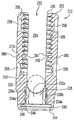
도 7은 도 1에 도시된 구현예의 확대 단면도이다.7 is an enlarged cross-sectional view of the embodiment shown in FIG. 1.
도 8은 도 7에 도시된 구현예의 분해 조립 사시도이다.8 is an exploded perspective view of the embodiment shown in FIG. 7.
도 9는 조절식 뼈 앵커 어셈블리의 하나의 구현예의 측면도이다.9 is a side view of one embodiment of an adjustable bone anchor assembly.
도 10은 도 9에 도시된 구현예의 분해 조립도이다.10 is an exploded view of the embodiment shown in FIG. 9.
도 11은 도 9에 도시된 수용기 부재의 하나의 구현예의 측면도이다.FIG. 11 is a side view of one embodiment of the receiver member shown in FIG. 9. FIG.
도 12는 도 11의 선 12-12를 따라 자르고, 화살표 방향으로 도시한, 도 11에 도시된 수용기 부재의 하나의 구현예의 단면도이다.FIG. 12 is a cross-sectional view of one embodiment of the receiver member shown in FIG. 11, taken along line 12-12 of FIG. 11 and shown in the direction of the arrow.
도 13은 도 9에 도시된 수용기 부재의 구현예의 정면도이다.FIG. 13 is a front view of an embodiment of the receiver member shown in FIG. 9. FIG.
도 14는 조절식 뼈 앵커 어셈블리의 하나의 구현예의 정면도이다.14 is a front view of one embodiment of an adjustable bone anchor assembly.
도 15는 도 14에 도시된 구현예의 분해 조립도이다.15 is an exploded view of the embodiment shown in FIG. 14.
도 16은 도 14의 위치에서 90도 회전한, 도 14에 도시한 구현예의 정면도이다.FIG. 16 is a front view of the embodiment shown in FIG. 14, rotated 90 degrees in the position of FIG. 14.
Claims (45)
Translated fromKoreanApplications Claiming Priority (2)
| Application Number | Priority Date | Filing Date | Title |
|---|---|---|---|
| US11/253,046US8075599B2 (en) | 2005-10-18 | 2005-10-18 | Adjustable bone anchor assembly |
| US11/253,046 | 2005-10-18 |
Publications (1)
| Publication Number | Publication Date |
|---|---|
| KR20080072848Atrue KR20080072848A (en) | 2008-08-07 |
Family
ID=37836697
Family Applications (1)
| Application Number | Title | Priority Date | Filing Date |
|---|---|---|---|
| KR1020087011763AWithdrawnKR20080072848A (en) | 2005-10-18 | 2006-10-03 | Adjustable bone anchor assembly |
Country Status (7)
| Country | Link |
|---|---|
| US (2) | US8075599B2 (en) |
| EP (1) | EP1945118A2 (en) |
| JP (1) | JP2009511227A (en) |
| KR (1) | KR20080072848A (en) |
| AU (1) | AU2006303883A1 (en) |
| CA (1) | CA2625230A1 (en) |
| WO (1) | WO2007047074A2 (en) |
Cited By (19)
| Publication number | Priority date | Publication date | Assignee | Title |
|---|---|---|---|---|
| WO2010065729A3 (en)* | 2008-12-03 | 2010-09-16 | Spartek Medical, Inc. | Low profile spinal prosthesis incorporating a bone anchor having a deflectable post and a compound spinal rod |
| US8007518B2 (en) | 2008-02-26 | 2011-08-30 | Spartek Medical, Inc. | Load-sharing component having a deflectable post and method for dynamic stabilization of the spine |
| US8012181B2 (en) | 2008-02-26 | 2011-09-06 | Spartek Medical, Inc. | Modular in-line deflection rod and bone anchor system and method for dynamic stabilization of the spine |
| US8016861B2 (en) | 2008-02-26 | 2011-09-13 | Spartek Medical, Inc. | Versatile polyaxial connector assembly and method for dynamic stabilization of the spine |
| US8021396B2 (en) | 2007-06-05 | 2011-09-20 | Spartek Medical, Inc. | Configurable dynamic spinal rod and method for dynamic stabilization of the spine |
| US8048115B2 (en) | 2007-06-05 | 2011-11-01 | Spartek Medical, Inc. | Surgical tool and method for implantation of a dynamic bone anchor |
| US8057515B2 (en) | 2008-02-26 | 2011-11-15 | Spartek Medical, Inc. | Load-sharing anchor having a deflectable post and centering spring and method for dynamic stabilization of the spine |
| US8083772B2 (en) | 2007-06-05 | 2011-12-27 | Spartek Medical, Inc. | Dynamic spinal rod assembly and method for dynamic stabilization of the spine |
| US8092501B2 (en) | 2007-06-05 | 2012-01-10 | Spartek Medical, Inc. | Dynamic spinal rod and method for dynamic stabilization of the spine |
| US8097024B2 (en) | 2008-02-26 | 2012-01-17 | Spartek Medical, Inc. | Load-sharing bone anchor having a deflectable post and method for stabilization of the spine |
| US8114134B2 (en) | 2007-06-05 | 2012-02-14 | Spartek Medical, Inc. | Spinal prosthesis having a three bar linkage for motion preservation and dynamic stabilization of the spine |
| US8211155B2 (en) | 2008-02-26 | 2012-07-03 | Spartek Medical, Inc. | Load-sharing bone anchor having a durable compliant member and method for dynamic stabilization of the spine |
| US8257397B2 (en) | 2009-12-02 | 2012-09-04 | Spartek Medical, Inc. | Low profile spinal prosthesis incorporating a bone anchor having a deflectable post and a compound spinal rod |
| US8267979B2 (en) | 2008-02-26 | 2012-09-18 | Spartek Medical, Inc. | Load-sharing bone anchor having a deflectable post and axial spring and method for dynamic stabilization of the spine |
| US8317836B2 (en) | 2007-06-05 | 2012-11-27 | Spartek Medical, Inc. | Bone anchor for receiving a rod for stabilization and motion preservation spinal implantation system and method |
| US8333792B2 (en) | 2008-02-26 | 2012-12-18 | Spartek Medical, Inc. | Load-sharing bone anchor having a deflectable post and method for dynamic stabilization of the spine |
| US8337536B2 (en) | 2008-02-26 | 2012-12-25 | Spartek Medical, Inc. | Load-sharing bone anchor having a deflectable post with a compliant ring and method for stabilization of the spine |
| US8430916B1 (en) | 2012-02-07 | 2013-04-30 | Spartek Medical, Inc. | Spinal rod connectors, methods of use, and spinal prosthesis incorporating spinal rod connectors |
| US8518085B2 (en) | 2010-06-10 | 2013-08-27 | Spartek Medical, Inc. | Adaptive spinal rod and methods for stabilization of the spine |
Families Citing this family (170)
| Publication number | Priority date | Publication date | Assignee | Title |
|---|---|---|---|---|
| US7833250B2 (en) | 2004-11-10 | 2010-11-16 | Jackson Roger P | Polyaxial bone screw with helically wound capture connection |
| US7862587B2 (en) | 2004-02-27 | 2011-01-04 | Jackson Roger P | Dynamic stabilization assemblies, tool set and method |
| US10729469B2 (en) | 2006-01-09 | 2020-08-04 | Roger P. Jackson | Flexible spinal stabilization assembly with spacer having off-axis core member |
| US8292926B2 (en) | 2005-09-30 | 2012-10-23 | Jackson Roger P | Dynamic stabilization connecting member with elastic core and outer sleeve |
| US8353932B2 (en) | 2005-09-30 | 2013-01-15 | Jackson Roger P | Polyaxial bone anchor assembly with one-piece closure, pressure insert and plastic elongate member |
| US10258382B2 (en) | 2007-01-18 | 2019-04-16 | Roger P. Jackson | Rod-cord dynamic connection assemblies with slidable bone anchor attachment members along the cord |
| US7842073B2 (en)* | 2002-04-18 | 2010-11-30 | Aesculap Ii, Inc. | Screw and rod fixation assembly and device |
| US6740086B2 (en) | 2002-04-18 | 2004-05-25 | Spinal Innovations, Llc | Screw and rod fixation assembly and device |
| US8876868B2 (en) | 2002-09-06 | 2014-11-04 | Roger P. Jackson | Helical guide and advancement flange with radially loaded lip |
| WO2006052796A2 (en) | 2004-11-10 | 2006-05-18 | Jackson Roger P | Helical guide and advancement flange with break-off extensions |
| US7621918B2 (en) | 2004-11-23 | 2009-11-24 | Jackson Roger P | Spinal fixation tool set and method |
| US6716214B1 (en) | 2003-06-18 | 2004-04-06 | Roger P. Jackson | Polyaxial bone screw with spline capture connection |
| US7377923B2 (en) | 2003-05-22 | 2008-05-27 | Alphatec Spine, Inc. | Variable angle spinal screw assembly |
| US7766915B2 (en) | 2004-02-27 | 2010-08-03 | Jackson Roger P | Dynamic fixation assemblies with inner core and outer coil-like member |
| US8137386B2 (en) | 2003-08-28 | 2012-03-20 | Jackson Roger P | Polyaxial bone screw apparatus |
| US7776067B2 (en) | 2005-05-27 | 2010-08-17 | Jackson Roger P | Polyaxial bone screw with shank articulation pressure insert and method |
| US8257398B2 (en) | 2003-06-18 | 2012-09-04 | Jackson Roger P | Polyaxial bone screw with cam capture |
| US8377102B2 (en) | 2003-06-18 | 2013-02-19 | Roger P. Jackson | Polyaxial bone anchor with spline capture connection and lower pressure insert |
| US8926670B2 (en) | 2003-06-18 | 2015-01-06 | Roger P. Jackson | Polyaxial bone screw assembly |
| US8398682B2 (en) | 2003-06-18 | 2013-03-19 | Roger P. Jackson | Polyaxial bone screw assembly |
| US7967850B2 (en) | 2003-06-18 | 2011-06-28 | Jackson Roger P | Polyaxial bone anchor with helical capture connection, insert and dual locking assembly |
| US7588575B2 (en) | 2003-10-21 | 2009-09-15 | Innovative Spinal Technologies | Extension for use with stabilization systems for internal structures |
| US9055934B2 (en)* | 2004-08-26 | 2015-06-16 | Zimmer Spine, Inc. | Methods and apparatus for access to and/or treatment of the spine |
| US11419642B2 (en) | 2003-12-16 | 2022-08-23 | Medos International Sarl | Percutaneous access devices and bone anchor assemblies |
| US7179261B2 (en) | 2003-12-16 | 2007-02-20 | Depuy Spine, Inc. | Percutaneous access devices and bone anchor assemblies |
| US7527638B2 (en) | 2003-12-16 | 2009-05-05 | Depuy Spine, Inc. | Methods and devices for minimally invasive spinal fixation element placement |
| US8152810B2 (en) | 2004-11-23 | 2012-04-10 | Jackson Roger P | Spinal fixation tool set and method |
| JP2007525274A (en) | 2004-02-27 | 2007-09-06 | ロジャー・ピー・ジャクソン | Orthopedic implant rod reduction instrument set and method |
| US11241261B2 (en) | 2005-09-30 | 2022-02-08 | Roger P Jackson | Apparatus and method for soft spinal stabilization using a tensionable cord and releasable end structure |
| US7160300B2 (en) | 2004-02-27 | 2007-01-09 | Jackson Roger P | Orthopedic implant rod reduction tool set and method |
| US7651502B2 (en) | 2004-09-24 | 2010-01-26 | Jackson Roger P | Spinal fixation tool set and method for rod reduction and fastener insertion |
| US8926672B2 (en) | 2004-11-10 | 2015-01-06 | Roger P. Jackson | Splay control closure for open bone anchor |
| US9216041B2 (en) | 2009-06-15 | 2015-12-22 | Roger P. Jackson | Spinal connecting members with tensioned cords and rigid sleeves for engaging compression inserts |
| WO2006057837A1 (en) | 2004-11-23 | 2006-06-01 | Jackson Roger P | Spinal fixation tool attachment structure |
| US9980753B2 (en) | 2009-06-15 | 2018-05-29 | Roger P Jackson | pivotal anchor with snap-in-place insert having rotation blocking extensions |
| US8444681B2 (en) | 2009-06-15 | 2013-05-21 | Roger P. Jackson | Polyaxial bone anchor with pop-on shank, friction fit retainer and winged insert |
| US9168069B2 (en) | 2009-06-15 | 2015-10-27 | Roger P. Jackson | Polyaxial bone anchor with pop-on shank and winged insert with lower skirt for engaging a friction fit retainer |
| US7875065B2 (en) | 2004-11-23 | 2011-01-25 | Jackson Roger P | Polyaxial bone screw with multi-part shank retainer and pressure insert |
| US8308782B2 (en) | 2004-11-23 | 2012-11-13 | Jackson Roger P | Bone anchors with longitudinal connecting member engaging inserts and closures for fixation and optional angulation |
| US8403962B2 (en) | 2005-02-22 | 2013-03-26 | Roger P. Jackson | Polyaxial bone screw assembly |
| US10076361B2 (en) | 2005-02-22 | 2018-09-18 | Roger P. Jackson | Polyaxial bone screw with spherical capture, compression and alignment and retention structures |
| US12102357B2 (en) | 2005-02-22 | 2024-10-01 | Roger P. Jackson | Pivotal bone anchor assembly with cannulated shank having a planar top surface and method of assembly |
| US7901437B2 (en) | 2007-01-26 | 2011-03-08 | Jackson Roger P | Dynamic stabilization member with molded connection |
| US8105368B2 (en) | 2005-09-30 | 2012-01-31 | Jackson Roger P | Dynamic stabilization connecting member with slitted core and outer sleeve |
| US8002806B2 (en)* | 2005-10-20 | 2011-08-23 | Warsaw Orthopedic, Inc. | Bottom loading multi-axial screw assembly |
| US8100946B2 (en) | 2005-11-21 | 2012-01-24 | Synthes Usa, Llc | Polyaxial bone anchors with increased angulation |
| US7927360B2 (en)* | 2006-01-26 | 2011-04-19 | Warsaw Orthopedic, Inc. | Spinal anchor assemblies having extended receivers |
| US8057519B2 (en)* | 2006-01-27 | 2011-11-15 | Warsaw Orthopedic, Inc. | Multi-axial screw assembly |
| US7722652B2 (en) | 2006-01-27 | 2010-05-25 | Warsaw Orthopedic, Inc. | Pivoting joints for spinal implants including designed resistance to motion and methods of use |
| US7833252B2 (en) | 2006-01-27 | 2010-11-16 | Warsaw Orthopedic, Inc. | Pivoting joints for spinal implants including designed resistance to motion and methods of use |
| USD589147S1 (en)* | 2006-02-02 | 2009-03-24 | Innovative Spinal Technologies | Bone anchor head |
| JP5210305B2 (en)* | 2006-06-16 | 2013-06-12 | アルファテック スパイン, インコーポレイテッド | Spinal screw assembly system, system for implanting spinal screw assembly |
| ES2334811T3 (en)* | 2006-11-17 | 2010-03-16 | Biedermann Motech Gmbh | OSEO ANCHORAGE DEVICE. |
| CA2670988C (en) | 2006-12-08 | 2014-03-25 | Roger P. Jackson | Tool system for dynamic spinal implants |
| US8475498B2 (en) | 2007-01-18 | 2013-07-02 | Roger P. Jackson | Dynamic stabilization connecting member with cord connection |
| US8366745B2 (en) | 2007-05-01 | 2013-02-05 | Jackson Roger P | Dynamic stabilization assembly having pre-compressed spacers with differential displacements |
| US10792074B2 (en) | 2007-01-22 | 2020-10-06 | Roger P. Jackson | Pivotal bone anchor assemly with twist-in-place friction fit insert |
| US8979904B2 (en) | 2007-05-01 | 2015-03-17 | Roger P Jackson | Connecting member with tensioned cord, low profile rigid sleeve and spacer with torsion control |
| US10383660B2 (en) | 2007-05-01 | 2019-08-20 | Roger P. Jackson | Soft stabilization assemblies with pretensioned cords |
| US9439681B2 (en) | 2007-07-20 | 2016-09-13 | DePuy Synthes Products, Inc. | Polyaxial bone fixation element |
| PL2170192T3 (en)* | 2007-07-20 | 2011-07-29 | Synthes Gmbh | Polyaxial bone fixation element |
| US20090182384A1 (en)* | 2008-01-14 | 2009-07-16 | Warsaw Orthopedic, Inc. | Material combinations for medical device implants |
| US8007522B2 (en) | 2008-02-04 | 2011-08-30 | Depuy Spine, Inc. | Methods for correction of spinal deformities |
| US8747407B2 (en)* | 2008-02-28 | 2014-06-10 | K2M, Inc. | Minimally invasive retractor and methods of use |
| US20090222044A1 (en)* | 2008-02-28 | 2009-09-03 | K2M, Inc. | Minimally Invasive Retractor Screw and Methods of Use |
| US9060813B1 (en) | 2008-02-29 | 2015-06-23 | Nuvasive, Inc. | Surgical fixation system and related methods |
| EP2265202B1 (en)* | 2008-04-22 | 2012-08-29 | Synthes GmbH | Bone fixation element with reduction tabs |
| AU2010260521C1 (en) | 2008-08-01 | 2013-08-01 | Roger P. Jackson | Longitudinal connecting member with sleeved tensioned cords |
| US20100036432A1 (en)* | 2008-08-05 | 2010-02-11 | Abbott Spine Inc. | Twist off reduction screw |
| EP2355725B1 (en) | 2008-09-05 | 2017-03-08 | Synthes GmbH | Bone fixation assembly |
| JP5815407B2 (en) | 2008-09-12 | 2015-11-17 | ジンテス ゲゼルシャフト ミット ベシュレンクテル ハフツング | Spinal stabilization and guided fixation system |
| KR20110081208A (en) | 2008-09-29 | 2011-07-13 | 신세스 게엠바하 | Multi-Axis Bottom-Loading Screw and Rod Assemblies |
| US20100087873A1 (en)* | 2008-10-06 | 2010-04-08 | Warsaw Orthopedics, Inc. | Surgical Connectors for Attaching an Elongated Member to a Bone |
| CA2742399A1 (en)* | 2008-11-03 | 2010-06-03 | Dustin M. Harvey | Uni-planar bone fixation assembly |
| US9247967B2 (en)* | 2008-12-03 | 2016-02-02 | Warsaw Orthopedic, Inc. | Rod and anchor system and method for using |
| US20100160978A1 (en)* | 2008-12-23 | 2010-06-24 | John Carbone | Bone screw assembly with non-uniform material |
| KR20120013312A (en) | 2009-04-15 | 2012-02-14 | 신세스 게엠바하 | Orthodontic Connectors for Spinal Structures |
| US11464549B2 (en) | 2009-06-15 | 2022-10-11 | Roger P. Jackson | Pivotal bone anchor assembly with horizontal tool engagement grooves and insert with upright arms having flared outer portions |
| US11229457B2 (en) | 2009-06-15 | 2022-01-25 | Roger P. Jackson | Pivotal bone anchor assembly with insert tool deployment |
| US8998959B2 (en) | 2009-06-15 | 2015-04-07 | Roger P Jackson | Polyaxial bone anchors with pop-on shank, fully constrained friction fit retainer and lock and release insert |
| CN103826560A (en)* | 2009-06-15 | 2014-05-28 | 罗杰.P.杰克逊 | Polyaxial Bone Anchor with Socket Stem and Winged Inserts with Friction Fit Compression Collars |
| US9668771B2 (en) | 2009-06-15 | 2017-06-06 | Roger P Jackson | Soft stabilization assemblies with off-set connector |
| CA2764841A1 (en) | 2009-06-17 | 2010-12-23 | Synthes Usa, Llc | Revision connector for spinal constructs |
| US8876869B1 (en) | 2009-06-19 | 2014-11-04 | Nuvasive, Inc. | Polyaxial bone screw assembly |
| EP2485654B1 (en) | 2009-10-05 | 2021-05-05 | Jackson P. Roger | Polyaxial bone anchor with non-pivotable retainer and pop-on shank, some with friction fit |
| US20110106173A1 (en)* | 2009-10-30 | 2011-05-05 | Warsaw Orthopedic, Inc. | Anchor Assembly With Directionally Controlled Saddle Adjustment And Transversely Adjustable Receiver |
| US20110106180A1 (en)* | 2009-10-30 | 2011-05-05 | Warsaw Orthopedic, Inc. | Implants With Adjustable Saddles |
| US8298275B2 (en)* | 2009-10-30 | 2012-10-30 | Warsaw Orthopedic, Inc. | Direct control spinal implant |
| US8430917B2 (en) | 2009-10-30 | 2013-04-30 | Warsaw Orthopedic, Inc. | Bone engaging implant with adjustment saddle |
| DE112010004338B4 (en) | 2009-11-10 | 2019-06-27 | Nuvasive, Inc. | DEVICE FOR IMPLEMENTING SPINE SURGERY |
| US8986349B1 (en) | 2009-11-11 | 2015-03-24 | Nuvasive, Inc. | Systems and methods for correcting spinal deformities |
| US8419778B2 (en)* | 2010-01-15 | 2013-04-16 | Ebi, Llc | Uniplanar bone anchor system |
| US8647370B2 (en)* | 2010-01-15 | 2014-02-11 | Ebi, Llc | Uniplanar bone anchor system |
| US8636655B1 (en) | 2010-01-19 | 2014-01-28 | Ronald Childs | Tissue retraction system and related methods |
| EP2606842B1 (en)* | 2010-03-29 | 2018-08-29 | Biedermann Technologies GmbH & Co. KG | Bone anchoring device |
| US12383311B2 (en) | 2010-05-14 | 2025-08-12 | Roger P. Jackson | Pivotal bone anchor assembly and method for use thereof |
| AU2011299558A1 (en) | 2010-09-08 | 2013-05-02 | Roger P. Jackson | Dynamic stabilization members with elastic and inelastic sections |
| US20120109208A1 (en)* | 2010-10-27 | 2012-05-03 | Warsaw Orthopedic, Inc. | Low Profile Extension Attachments for Bone Anchors |
| AU2011324058A1 (en) | 2010-11-02 | 2013-06-20 | Roger P. Jackson | Polyaxial bone anchor with pop-on shank and pivotable retainer |
| CN102525635B (en)* | 2010-12-10 | 2014-12-31 | 上海微创骨科医疗科技有限公司 | Universal pedicle screw |
| CN102068303B (en)* | 2011-01-13 | 2013-04-03 | 邱勇 | Pedicle screw |
| US9198692B1 (en) | 2011-02-10 | 2015-12-01 | Nuvasive, Inc. | Spinal fixation anchor |
| US9387013B1 (en) | 2011-03-01 | 2016-07-12 | Nuvasive, Inc. | Posterior cervical fixation system |
| JP5865479B2 (en) | 2011-03-24 | 2016-02-17 | ロジャー・ピー・ジャクソン | Multiaxial bone anchor with compound joint and pop-mounted shank |
| US9307972B2 (en) | 2011-05-10 | 2016-04-12 | Nuvasive, Inc. | Method and apparatus for performing spinal fusion surgery |
| US11076887B2 (en)* | 2011-07-15 | 2021-08-03 | Globus Medical, Inc. | Orthopedic fixation devices and methods of installation thereof |
| US9060818B2 (en) | 2011-09-01 | 2015-06-23 | DePuy Synthes Products, Inc. | Bone implants |
| US8663291B2 (en)* | 2011-10-28 | 2014-03-04 | Ortho Innovations, Llc | Top loading polyaxial ball and socket fastener |
| US9622788B2 (en) | 2011-11-02 | 2017-04-18 | Warsaw Orthopedic, Inc. | Implant assembly with a rigid interface |
| EP2604204B1 (en)* | 2011-12-13 | 2014-10-01 | Biedermann Technologies GmbH & Co. KG | Monoplanar bone anchoring device with selectable pivot plane |
| US8911479B2 (en) | 2012-01-10 | 2014-12-16 | Roger P. Jackson | Multi-start closures for open implants |
| US9271759B2 (en) | 2012-03-09 | 2016-03-01 | Institute Of Musculoskeletal Science And Education, Ltd. | Pedicle screw assembly with locking cap |
| US9782204B2 (en) | 2012-09-28 | 2017-10-10 | Medos International Sarl | Bone anchor assemblies |
| US9101426B2 (en) | 2012-10-11 | 2015-08-11 | Stryker Trauma Sa | Cable plug |
| US8911478B2 (en) | 2012-11-21 | 2014-12-16 | Roger P. Jackson | Splay control closure for open bone anchor |
| DE102013100574A1 (en)* | 2013-01-21 | 2014-07-24 | Aesculap Ag | Implant system and fastener for an implant system |
| US10058354B2 (en) | 2013-01-28 | 2018-08-28 | Roger P. Jackson | Pivotal bone anchor assembly with frictional shank head seating surfaces |
| US8852239B2 (en) | 2013-02-15 | 2014-10-07 | Roger P Jackson | Sagittal angle screw with integral shank and receiver |
| US20140257411A1 (en)* | 2013-03-08 | 2014-09-11 | Warsaw Orthopedic, Inc. | Bone fastener and methods of use |
| US9775660B2 (en) | 2013-03-14 | 2017-10-03 | DePuy Synthes Products, Inc. | Bottom-loading bone anchor assemblies and methods |
| US9259247B2 (en) | 2013-03-14 | 2016-02-16 | Medos International Sarl | Locking compression members for use with bone anchor assemblies and methods |
| US10342582B2 (en) | 2013-03-14 | 2019-07-09 | DePuy Synthes Products, Inc. | Bone anchor assemblies and methods with improved locking |
| US9724145B2 (en) | 2013-03-14 | 2017-08-08 | Medos International Sarl | Bone anchor assemblies with multiple component bottom loading bone anchors |
| US20140277153A1 (en) | 2013-03-14 | 2014-09-18 | DePuy Synthes Products, LLC | Bone Anchor Assemblies and Methods With Improved Locking |
| WO2014169189A1 (en)* | 2013-04-12 | 2014-10-16 | Alphatec Spine, Inc. | Uniplanar screw assembly and methods of use |
| US9566092B2 (en) | 2013-10-29 | 2017-02-14 | Roger P. Jackson | Cervical bone anchor with collet retainer and outer locking sleeve |
| US12016595B2 (en)* | 2013-11-22 | 2024-06-25 | Spinal Balance, Inc. | Poly-axial pedicle screw assembly and packaging therefor |
| US9744050B1 (en) | 2013-12-06 | 2017-08-29 | Stryker European Holdings I, Llc | Compression and distraction system for percutaneous posterior spinal fusion |
| US9408716B1 (en) | 2013-12-06 | 2016-08-09 | Stryker European Holdings I, Llc | Percutaneous posterior spinal fusion implant construction and method |
| US10159579B1 (en) | 2013-12-06 | 2018-12-25 | Stryker European Holdings I, Llc | Tubular instruments for percutaneous posterior spinal fusion systems and methods |
| US9717533B2 (en) | 2013-12-12 | 2017-08-01 | Roger P. Jackson | Bone anchor closure pivot-splay control flange form guide and advancement structure |
| US9451993B2 (en) | 2014-01-09 | 2016-09-27 | Roger P. Jackson | Bi-radial pop-on cervical bone anchor |
| US9597119B2 (en) | 2014-06-04 | 2017-03-21 | Roger P. Jackson | Polyaxial bone anchor with polymer sleeve |
| US10064658B2 (en) | 2014-06-04 | 2018-09-04 | Roger P. Jackson | Polyaxial bone anchor with insert guides |
| US10499968B2 (en) | 2014-08-08 | 2019-12-10 | Stryker European Holdings I, Llc | Cable plugs for bone plates |
| US9795370B2 (en) | 2014-08-13 | 2017-10-24 | Nuvasive, Inc. | Minimally disruptive retractor and associated methods for spinal surgery |
| EP3209220B1 (en)* | 2014-10-21 | 2019-09-25 | Roger P. Jackson | Snap-on multi-planar and mono-planar receiver assemblies having integral and multi-part multipurpose positioners for pivoting and non-pivoting retainers |
| US10543021B2 (en)* | 2014-10-21 | 2020-01-28 | Roger P. Jackson | Pivotal bone anchor assembly having an open ring positioner for a retainer |
| US9924975B2 (en)* | 2014-10-21 | 2018-03-27 | Roger P. Jackson | Bone anchor having a snap-fit assembly |
| US20160220277A1 (en)* | 2015-02-04 | 2016-08-04 | Warsaw Orthopedic, Inc. | Spinal implant system and methods of use |
| US9707013B2 (en)* | 2015-04-30 | 2017-07-18 | Warsaw Orthopedic, Inc. | Spinal implant system and methods of use |
| JP6643364B2 (en) | 2015-06-25 | 2020-02-12 | インスティテュート フォー マスキュロスケレタル サイエンス アンド エジュケイション,リミテッド | Interbody fusion device and system for implantation |
| US20170020573A1 (en)* | 2015-07-20 | 2017-01-26 | Amendia, Inc. | Pedicle screw tulip assembly with multi-segmented member |
| US20170035462A1 (en)* | 2015-08-06 | 2017-02-09 | GS Medical Inc. | Uniplanar pedicle fastener |
| EP3334355B1 (en) | 2015-08-13 | 2024-04-10 | K2M, Inc. | Extended tab systems for reducing spinal rods |
| US9956003B2 (en)* | 2015-09-18 | 2018-05-01 | Warsaw Orthopedic, Inc | Spinal implant system and methods of use |
| US20170290608A1 (en)* | 2016-01-22 | 2017-10-12 | Spinal Usa, Inc. | Spinal fixation systems and methods |
| US10307265B2 (en) | 2016-10-18 | 2019-06-04 | Institute for Musculoskeletal Science and Education, Ltd. | Implant with deployable blades |
| US10405992B2 (en) | 2016-10-25 | 2019-09-10 | Institute for Musculoskeletal Science and Education, Ltd. | Spinal fusion implant |
| CN108606859B (en)* | 2016-12-12 | 2024-04-02 | 创生医疗器械(中国)有限公司 | Locked lumbar fusion device |
| US10610265B1 (en) | 2017-07-31 | 2020-04-07 | K2M, Inc. | Polyaxial bone screw with increased angulation |
| US10653455B2 (en)* | 2017-09-12 | 2020-05-19 | Warsaw Orthopedic, Inc. | Spinal implant system and methods of use |
| US10695102B2 (en)* | 2017-12-15 | 2020-06-30 | Warsaw Orthopedic, Inc. | Spinal implant system and methods of use |
| US11241259B2 (en) | 2018-08-30 | 2022-02-08 | Zimmer Biomet Spine, Inc. | Bone anchor |
| US11596449B2 (en) | 2018-09-13 | 2023-03-07 | Roger P. Jackson | Pivotal bone anchor assembly with modular receiver and universal shank head |
| WO2020097691A1 (en)* | 2018-11-16 | 2020-05-22 | Southern Cross Patents Pty Ltd | Pedicle screws |
| US11559333B2 (en) | 2019-01-21 | 2023-01-24 | Zimmer Biomet Spine, Inc. | Bone anchor |
| WO2021263088A1 (en)* | 2020-06-26 | 2021-12-30 | K2M, Inc. | Modular head assembly |
| US11311316B2 (en)* | 2020-09-04 | 2022-04-26 | Warsaw Orthopedic, Inc. | Spinal implant system and methods of use |
| WO2022108875A1 (en) | 2020-11-19 | 2022-05-27 | K2M, Inc. | Modular head assembly for spinal fixation |
| WO2022184797A1 (en) | 2021-03-05 | 2022-09-09 | Medos International Sarl | Selectively locking polyaxial screw |
| US11291477B1 (en) | 2021-05-04 | 2022-04-05 | Warsaw Orthopedic, Inc. | Dorsal adjusting implant and methods of use |
| US11432848B1 (en) | 2021-05-12 | 2022-09-06 | Warsaw Orthopedic, Inc. | Top loading quick lock construct |
| US11712270B2 (en) | 2021-05-17 | 2023-08-01 | Warsaw Orthopedic, Inc. | Quick lock clamp constructs and associated methods |
| US11751915B2 (en) | 2021-07-09 | 2023-09-12 | Roger P. Jackson | Modular spinal fixation system with bottom-loaded universal shank heads |
| US11944357B2 (en)* | 2021-08-20 | 2024-04-02 | Snj Patents, Llc | Minimally invasive surgery add on screw system |
| US11957391B2 (en) | 2021-11-01 | 2024-04-16 | Warsaw Orthopedic, Inc. | Bone screw having an overmold of a shank |
| US12053209B2 (en) | 2022-01-18 | 2024-08-06 | Roger P. Jackson | Spinal fixation systems with modular receiver and ring retainer sub-assemblies for connecting with universal shank heads |
| US11857222B1 (en)* | 2022-06-17 | 2024-01-02 | Globus Medical Inc. | Modular screw head assemblies |
| US12414801B2 (en) | 2022-11-03 | 2025-09-16 | Roger P. Jackson | Spinal fixation system with modular receiver sub-assemblies for connecting with bi-spherical universal shank heads |
Family Cites Families (48)
| Publication number | Priority date | Publication date | Assignee | Title |
|---|---|---|---|---|
| DE3614101C1 (en) | 1986-04-25 | 1987-10-22 | Juergen Prof Dr Med Harms | Pedicle screw |
| CH685850A5 (en) | 1990-11-26 | 1995-10-31 | Synthes Ag | anchoring device |
| DE4107480C2 (en) | 1991-03-08 | 1994-09-22 | Heinrich Ulrich | Pedicle screw for implants to correct and stabilize the spine |
| DE9202745U1 (en) | 1992-03-02 | 1992-04-30 | Howmedica Gmbh, 2314 Schoenkirchen | Device for bracing vertebrae of the human spine |
| DE59301618D1 (en) | 1992-06-04 | 1996-03-28 | Synthes Ag | Osteosynthetic fastener |
| DE4243951C2 (en) | 1992-12-23 | 1997-07-03 | Plus Endoprothetik Ag | Device for stiffening a spinal column section consisting of at least two vertebrae |
| US5499983A (en) | 1994-02-23 | 1996-03-19 | Smith & Nephew Richards, Inc. | Variable angle spinal screw |
| DE4425357C2 (en) | 1994-07-18 | 1996-07-04 | Harms Juergen | Anchoring element |
| DE4436262C1 (en) | 1994-10-11 | 1996-07-25 | Schaefer Micomed Gmbh | Resetting screw, especially for vertebrae, with shank and grooved fork head |
| DE19509332C1 (en) | 1995-03-15 | 1996-08-14 | Harms Juergen | Anchoring element |
| US5562661A (en) | 1995-03-16 | 1996-10-08 | Alphatec Manufacturing Incorporated | Top tightening bone fixation apparatus |
| DE19605640C2 (en) | 1996-02-15 | 2002-08-14 | Peter Griss | Osteosynthetic fastener |
| US5885286A (en) | 1996-09-24 | 1999-03-23 | Sdgi Holdings, Inc. | Multi-axial bone screw assembly |
| IL124529A (en) | 1997-05-20 | 2001-08-08 | Akiva Raphael Katz | Pedicle screw assembly |
| DE19829699A1 (en) | 1998-07-02 | 2000-01-20 | Med Medical Engineering Dev Lt | Osteosynthetic fixing device, comprising of anchor segment and two fork-shaped upper ends with predetermined break points, operated with adjustment rod, tightening bolt, and knurled nut |
| JP2000046135A (en) | 1998-07-28 | 2000-02-18 | Nissan Motor Co Ltd | Transmission control device for toroidal type continuously variable transmission |
| US6296642B1 (en) | 1998-11-09 | 2001-10-02 | Sdgi Holdings, Inc. | Reverse angle thread for preventing splaying in medical devices |
| US6280442B1 (en) | 1999-09-01 | 2001-08-28 | Sdgi Holdings, Inc. | Multi-axial bone screw assembly |
| US6485491B1 (en)* | 2000-09-15 | 2002-11-26 | Sdgi Holdings, Inc. | Posterior fixation system |
| DE10055888C1 (en) | 2000-11-10 | 2002-04-25 | Biedermann Motech Gmbh | Bone screw, has connector rod receiving part with unsymmetrically arranged end bores |
| US6770075B2 (en) | 2001-05-17 | 2004-08-03 | Robert S. Howland | Spinal fixation apparatus with enhanced axial support and methods for use |
| JP4180506B2 (en)* | 2001-06-27 | 2008-11-12 | デピュイ・プロダクツ・インコーポレイテッド | Minimally invasive orthopedic device and method |
| US6800079B2 (en)* | 2002-03-15 | 2004-10-05 | Lock-N-Stitch, Inc. | Orthopedic stabilization device and method |
| US6800078B2 (en) | 2001-11-07 | 2004-10-05 | Lock-N-Stitch, Inc. | Orthopedic stabilization device and method |
| US6692500B2 (en) | 2001-10-15 | 2004-02-17 | Gary Jack Reed | Orthopedic stabilization device and method |
| US6837889B2 (en) | 2002-03-01 | 2005-01-04 | Endius Incorporated | Apparatus for connecting a longitudinal member to a bone portion |
| US6740086B2 (en) | 2002-04-18 | 2004-05-25 | Spinal Innovations, Llc | Screw and rod fixation assembly and device |
| WO2003096916A1 (en) | 2002-05-21 | 2003-11-27 | Peter Metz-Stavenhagen | Anchoring element for securing a rod on a vertebra |
| DE20207851U1 (en) | 2002-05-21 | 2002-10-10 | Metz-Stavenhagen, Peter, Dr.med., 34537 Bad Wildungen | Anchoring element for fastening a rod of a device for setting up a human or animal spine to a vertebral bone |
| DE20207847U1 (en) | 2002-05-21 | 2002-10-10 | Metz-Stavenhagen, Peter, Dr.med., 34537 Bad Wildungen | Device for setting up a human or animal spine and fastening element therefor |
| AU2003287273C1 (en) | 2002-10-30 | 2010-01-07 | Zimmer Spine, Inc. | Spinal stabilization system insertion and methods |
| DE10319781B3 (en) | 2003-04-30 | 2004-08-26 | Biedermann Motech Gmbh | Bone anchor, to attach a component to the bone, has a head to hold the component and a shaft with screw thread sections and thread-free sections along the shaft length |
| US7377923B2 (en) | 2003-05-22 | 2008-05-27 | Alphatec Spine, Inc. | Variable angle spinal screw assembly |
| FR2855392B1 (en) | 2003-05-28 | 2005-08-05 | Spinevision | CONNECTION DEVICE FOR SPINAL OSTESYNTHESIS |
| WO2005065397A2 (en) | 2003-12-30 | 2005-07-21 | Depuy Spine Sarl | Bone anchor assemblies |
| JP2007516811A (en) | 2003-12-30 | 2007-06-28 | デピュイ・スパイン・エスエイアールエル | Bone anchor assembly and method for manufacturing bone anchor assembly |
| US7678137B2 (en) | 2004-01-13 | 2010-03-16 | Life Spine, Inc. | Pedicle screw constructs for spine fixation systems |
| US7678139B2 (en) | 2004-04-20 | 2010-03-16 | Allez Spine, Llc | Pedicle screw assembly |
| US7559943B2 (en)* | 2004-06-09 | 2009-07-14 | Zimmer Spine, Inc. | Spinal fixation device with internal drive structure |
| US20060084978A1 (en)* | 2004-09-30 | 2006-04-20 | Mokhtar Mourad B | Spinal fixation system and method |
| US7794477B2 (en)* | 2004-10-05 | 2010-09-14 | Warsaw Orthopedic, Inc. | Spinal implants and methods with extended multi-axial anchor assemblies |
| WO2006047555A2 (en)* | 2004-10-25 | 2006-05-04 | Alphaspine, Inc. | Bone fixation systems and methods |
| DE102005005647A1 (en) | 2005-02-08 | 2006-08-17 | Henning Kloss | Pedicle screw for spinal column stabilizing device, has screw head with two opposed oblong hole shaped recesses, and ball unit including recess for accommodating connecting unit and movably mounted in head |
| US7951172B2 (en)* | 2005-03-04 | 2011-05-31 | Depuy Spine Sarl | Constrained motion bone screw assembly |
| US8002806B2 (en) | 2005-10-20 | 2011-08-23 | Warsaw Orthopedic, Inc. | Bottom loading multi-axial screw assembly |
| US7722652B2 (en)* | 2006-01-27 | 2010-05-25 | Warsaw Orthopedic, Inc. | Pivoting joints for spinal implants including designed resistance to motion and methods of use |
| US8048128B2 (en) | 2007-06-05 | 2011-11-01 | Spartek Medical, Inc. | Revision system and method for a dynamic stabilization and motion preservation spinal implantation system and method |
| FR2925288B1 (en) | 2007-12-21 | 2010-01-15 | Michel Timoteo | SWIVEL CONNECTING DEVICE FOR SPINAL OSTEOSYNTHESIS SCREW |
- 2005
- 2005-10-18USUS11/253,046patent/US8075599B2/enactiveActive
- 2006
- 2006-10-03EPEP06815945Apatent/EP1945118A2/ennot_activeWithdrawn
- 2006-10-03CACA002625230Apatent/CA2625230A1/ennot_activeAbandoned
- 2006-10-03JPJP2008536596Apatent/JP2009511227A/enactivePending
- 2006-10-03AUAU2006303883Apatent/AU2006303883A1/ennot_activeAbandoned
- 2006-10-03KRKR1020087011763Apatent/KR20080072848A/ennot_activeWithdrawn
- 2006-10-03WOPCT/US2006/038312patent/WO2007047074A2/enactiveApplication Filing
- 2011
- 2011-08-17USUS13/211,993patent/US9155566B2/enactiveActive
Cited By (26)
| Publication number | Priority date | Publication date | Assignee | Title |
|---|---|---|---|---|
| US8317836B2 (en) | 2007-06-05 | 2012-11-27 | Spartek Medical, Inc. | Bone anchor for receiving a rod for stabilization and motion preservation spinal implantation system and method |
| US8083772B2 (en) | 2007-06-05 | 2011-12-27 | Spartek Medical, Inc. | Dynamic spinal rod assembly and method for dynamic stabilization of the spine |
| US8568451B2 (en) | 2007-06-05 | 2013-10-29 | Spartek Medical, Inc. | Bone anchor for receiving a rod for stabilization and motion preservation spinal implantation system and method |
| US8114134B2 (en) | 2007-06-05 | 2012-02-14 | Spartek Medical, Inc. | Spinal prosthesis having a three bar linkage for motion preservation and dynamic stabilization of the spine |
| US8021396B2 (en) | 2007-06-05 | 2011-09-20 | Spartek Medical, Inc. | Configurable dynamic spinal rod and method for dynamic stabilization of the spine |
| US8092501B2 (en) | 2007-06-05 | 2012-01-10 | Spartek Medical, Inc. | Dynamic spinal rod and method for dynamic stabilization of the spine |
| US8048115B2 (en) | 2007-06-05 | 2011-11-01 | Spartek Medical, Inc. | Surgical tool and method for implantation of a dynamic bone anchor |
| US8333792B2 (en) | 2008-02-26 | 2012-12-18 | Spartek Medical, Inc. | Load-sharing bone anchor having a deflectable post and method for dynamic stabilization of the spine |
| US8337536B2 (en) | 2008-02-26 | 2012-12-25 | Spartek Medical, Inc. | Load-sharing bone anchor having a deflectable post with a compliant ring and method for stabilization of the spine |
| US8083775B2 (en) | 2008-02-26 | 2011-12-27 | Spartek Medical, Inc. | Load-sharing bone anchor having a natural center of rotation and method for dynamic stabilization of the spine |
| US8057515B2 (en) | 2008-02-26 | 2011-11-15 | Spartek Medical, Inc. | Load-sharing anchor having a deflectable post and centering spring and method for dynamic stabilization of the spine |
| US8048125B2 (en) | 2008-02-26 | 2011-11-01 | Spartek Medical, Inc. | Versatile offset polyaxial connector and method for dynamic stabilization of the spine |
| US8007518B2 (en) | 2008-02-26 | 2011-08-30 | Spartek Medical, Inc. | Load-sharing component having a deflectable post and method for dynamic stabilization of the spine |
| US8012181B2 (en) | 2008-02-26 | 2011-09-06 | Spartek Medical, Inc. | Modular in-line deflection rod and bone anchor system and method for dynamic stabilization of the spine |
| US8016861B2 (en) | 2008-02-26 | 2011-09-13 | Spartek Medical, Inc. | Versatile polyaxial connector assembly and method for dynamic stabilization of the spine |
| US8057517B2 (en) | 2008-02-26 | 2011-11-15 | Spartek Medical, Inc. | Load-sharing component having a deflectable post and centering spring and method for dynamic stabilization of the spine |
| US8097024B2 (en) | 2008-02-26 | 2012-01-17 | Spartek Medical, Inc. | Load-sharing bone anchor having a deflectable post and method for stabilization of the spine |
| US8267979B2 (en) | 2008-02-26 | 2012-09-18 | Spartek Medical, Inc. | Load-sharing bone anchor having a deflectable post and axial spring and method for dynamic stabilization of the spine |
| US8211155B2 (en) | 2008-02-26 | 2012-07-03 | Spartek Medical, Inc. | Load-sharing bone anchor having a durable compliant member and method for dynamic stabilization of the spine |
| US8216281B2 (en) | 2008-12-03 | 2012-07-10 | Spartek Medical, Inc. | Low profile spinal prosthesis incorporating a bone anchor having a deflectable post and a compound spinal rod |
| WO2010065729A3 (en)* | 2008-12-03 | 2010-09-16 | Spartek Medical, Inc. | Low profile spinal prosthesis incorporating a bone anchor having a deflectable post and a compound spinal rod |
| US8257397B2 (en) | 2009-12-02 | 2012-09-04 | Spartek Medical, Inc. | Low profile spinal prosthesis incorporating a bone anchor having a deflectable post and a compound spinal rod |
| US8372122B2 (en) | 2009-12-02 | 2013-02-12 | Spartek Medical, Inc. | Low profile spinal prosthesis incorporating a bone anchor having a deflectable post and a compound spinal rod |
| US8394127B2 (en) | 2009-12-02 | 2013-03-12 | Spartek Medical, Inc. | Low profile spinal prosthesis incorporating a bone anchor having a deflectable post and a compound spinal rod |
| US8518085B2 (en) | 2010-06-10 | 2013-08-27 | Spartek Medical, Inc. | Adaptive spinal rod and methods for stabilization of the spine |
| US8430916B1 (en) | 2012-02-07 | 2013-04-30 | Spartek Medical, Inc. | Spinal rod connectors, methods of use, and spinal prosthesis incorporating spinal rod connectors |
Also Published As
| Publication number | Publication date |
|---|---|
| AU2006303883A1 (en) | 2007-04-26 |
| JP2009511227A (en) | 2009-03-19 |
| CA2625230A1 (en) | 2007-04-26 |
| US9155566B2 (en) | 2015-10-13 |
| US20110301650A1 (en) | 2011-12-08 |
| US8075599B2 (en) | 2011-12-13 |
| WO2007047074A2 (en) | 2007-04-26 |
| EP1945118A2 (en) | 2008-07-23 |
| WO2007047074A3 (en) | 2007-10-25 |
| US20070088357A1 (en) | 2007-04-19 |
Similar Documents
| Publication | Publication Date | Title |
|---|---|---|
| KR20080072848A (en) | Adjustable bone anchor assembly | |
| JP4767261B2 (en) | Lateral loading bone anchor | |
| JP4390709B2 (en) | Variable angle adaptive plate | |
| JP5599316B2 (en) | Surgical fixation system and related methods | |
| CN100430029C (en) | Multi-axial orthopedic device and system for spinal surgery | |
| AU773530B2 (en) | Multi-axial bone screw assembly | |
| US7144396B2 (en) | Apparatus for connecting a longitudinal member to a bone portion | |
| US20090093843A1 (en) | Dynamic spine stabilization system | |
| US7909855B2 (en) | Orthopedic implant assembly | |
| US8740947B2 (en) | Multiple lead bone fixation apparatus | |
| JP2007516811A (en) | Bone anchor assembly and method for manufacturing bone anchor assembly | |
| JP2009514652A (en) | Rear adjustment multiple rod connector | |
| JP2009517174A (en) | Side mounted adjustable bone anchor | |
| US11944357B2 (en) | Minimally invasive surgery add on screw system | |
| US20240206918A1 (en) | Minimally invasive surgery add on screw system | |
| KR20080084997A (en) | Side mounted adjustable bone anchor |
Legal Events
| Date | Code | Title | Description |
|---|---|---|---|
| PA0105 | International application | Patent event date:20080516 Patent event code:PA01051R01D Comment text:International Patent Application | |
| PG1501 | Laying open of application | ||
| PC1203 | Withdrawal of no request for examination | ||
| WITN | Application deemed withdrawn, e.g. because no request for examination was filed or no examination fee was paid |