KR20080064568A - Display device that displays video input through various connectors - Google Patents
Display device that displays video input through various connectorsDownload PDFInfo
- Publication number
- KR20080064568A KR20080064568AKR1020070001614AKR20070001614AKR20080064568AKR 20080064568 AKR20080064568 AKR 20080064568AKR 1020070001614 AKR1020070001614 AKR 1020070001614AKR 20070001614 AKR20070001614 AKR 20070001614AKR 20080064568 AKR20080064568 AKR 20080064568A
- Authority
- KR
- South Korea
- Prior art keywords
- connector
- signal
- video signal
- image
- video
- Prior art date
- Legal status (The legal status is an assumption and is not a legal conclusion. Google has not performed a legal analysis and makes no representation as to the accuracy of the status listed.)
- Ceased
Links
Images


Classifications
- H—ELECTRICITY
- H04—ELECTRIC COMMUNICATION TECHNIQUE
- H04N—PICTORIAL COMMUNICATION, e.g. TELEVISION
- H04N5/00—Details of television systems
- H04N5/44—Receiver circuitry for the reception of television signals according to analogue transmission standards
- G—PHYSICS
- G09—EDUCATION; CRYPTOGRAPHY; DISPLAY; ADVERTISING; SEALS
- G09G—ARRANGEMENTS OR CIRCUITS FOR CONTROL OF INDICATING DEVICES USING STATIC MEANS TO PRESENT VARIABLE INFORMATION
- G09G5/00—Control arrangements or circuits for visual indicators common to cathode-ray tube indicators and other visual indicators
- G09G5/003—Details of a display terminal, the details relating to the control arrangement of the display terminal and to the interfaces thereto
- G09G5/006—Details of the interface to the display terminal
- G—PHYSICS
- G09—EDUCATION; CRYPTOGRAPHY; DISPLAY; ADVERTISING; SEALS
- G09G—ARRANGEMENTS OR CIRCUITS FOR CONTROL OF INDICATING DEVICES USING STATIC MEANS TO PRESENT VARIABLE INFORMATION
- G09G2370/00—Aspects of data communication
- G09G2370/04—Exchange of auxiliary data, i.e. other than image data, between monitor and graphics controller
- G09G2370/045—Exchange of auxiliary data, i.e. other than image data, between monitor and graphics controller using multiple communication channels, e.g. parallel and serial
- G09G2370/047—Exchange of auxiliary data, i.e. other than image data, between monitor and graphics controller using multiple communication channels, e.g. parallel and serial using display data channel standard [DDC] communication
Landscapes
- Engineering & Computer Science (AREA)
- Physics & Mathematics (AREA)
- Computer Hardware Design (AREA)
- General Physics & Mathematics (AREA)
- Theoretical Computer Science (AREA)
- Multimedia (AREA)
- Signal Processing (AREA)
- Controls And Circuits For Display Device (AREA)
- Control Of Indicators Other Than Cathode Ray Tubes (AREA)
- Two-Way Televisions, Distribution Of Moving Picture Or The Like (AREA)
Abstract
Translated fromKoreanDescription
Translated fromKorean도 1은 본 발명의 일 실시예에 따른 모니터의 블럭도,1 is a block diagram of a monitor according to an embodiment of the present invention;
도 2는 DVI-I 커넥터를 도시한 도면,2 shows a DVI-I connector,
도 3은 USB 커넥터를 도시한 도면,3 shows a USB connector,
도 4는 본 발명의 다른 실시예에 따른 모니터의 블럭도,4 is a block diagram of a monitor according to another embodiment of the present invention;
도 5는 D-sub 커넥터를 도시한 도면,5 shows a D-sub connector;
도 6은 본 발명의 또 다른 실시예에 따른 모니터의 블럭도, 그리고,6 is a block diagram of a monitor according to another embodiment of the present invention, and
도 7은 도 6에 도시된 모니터가 입력되는 영상을 선택적으로 디스플레이하는 과정의 설명에 제공되는 흐름도이다.FIG. 7 is a flowchart provided to explain a process of selectively displaying an input image of the monitor illustrated in FIG. 6.
* 도면의 주요 부분에 대한 부호의 설명 *Explanation of symbols on the main parts of the drawings
110 : DVI 커넥터120 : D-sub 커넥터110: DVI connector 120: D-sub connector
130 : USB 커넥터140 : 스위칭부130: USB connector 140: switching unit
150 : 영상신호 처리부160 : 디스플레이 패널150: image signal processor 160: display panel
170 : 제어부170: control unit
본 발명은 디스플레이 장치에 관한 것으로, 더욱 상세하게는 외부기기로부터 입력되는 영상을 디스플레이하여 사용자에게 제공하는 디스플레이 장치에 관한 것이다.The present invention relates to a display device, and more particularly, to a display device for displaying an image input from an external device and providing the same to a user.
디스플레이 장치로서 가장 대표적인 것이라 할 수 있는 모니터는 PC로부터 전달되는 영상을 화면에 표시하는데 주로 이용된다.The most representative monitor as a display device is mainly used to display an image transmitted from a PC on a screen.
모니터에는 PC로부터 영상을 전달받기 위한 커넥터로 DVI 커넥터 및/또는 D-sub 커넥터를 구비하고 있다. 따라서, PC에서 모니터로 영상이 전달되려면, PC에도 DVI 커넥터 또는 D-sub 커넥터가 구비되어 있어야 한다.The monitor is equipped with a DVI connector and / or a D-sub connector as a connector for receiving images from a PC. Therefore, in order to transfer images from the PC to the monitor, the PC must also be equipped with a DVI connector or a D-sub connector.
PC에 마련되는 DVI 커넥터와 D-sub 커넥터의 개수는 한정되어 있다. 이는 PC에 연결될 수 있는 모니터의 개수를 한정하는 요인으로 작용한다. 따라서, PC에 마련되어 있는 DVI 커넥터와 D-sub 커넥터의 개수 보다 더 많은 개수의 모니터를 PC에 연결하려면, DVI 커넥터 또는 D-sub 커넥터가 구비되어 있는 별도의 하드웨어(비디오 카드)를 추가하여야 하는 문제를 유발하게 된다.The number of DVI and D-sub connectors on a PC is limited. This limits the number of monitors that can be connected to a PC. Therefore, if you want to connect more monitors to your PC than the number of DVI and D-sub connectors on your PC, you will need to add additional hardware (video cards) equipped with DVI or D-sub connectors. Will cause.
또한, DVI 커넥터/D-sub 커넥터에 연결되는 DVI 케이블/D-sub 케이블은 많은 라인들로 이루어지기 때문에 가격이 비싼 편이다.Also, the DVI cable / D-sub cable connected to the DVI connector / D-sub connector is expensive because it consists of many lines.
본 발명은 상기와 같은 문제점을 해결하기 위하여 안출된 것으로서, 본 발명의 목적은, PC에 별도의 하드웨어 추가 없이 여러 개의 모니터를 연결하기 위한 방안으로, 다양한 커넥터를 통해 입력되는 영상을 디스플레이하는 디스플레이 장치를 제공함에 있다.The present invention has been made to solve the above problems, an object of the present invention, a method for connecting a plurality of monitors without additional hardware to the PC, a display device for displaying an image input through a variety of connectors In providing.
상기 목적을 달성하기 위한 본 발명에 따른, 디스플레이 장치는, 제1 영상신호를 입력받는 제1 커넥터; 제2 영상신호를 입력받는 제2 커넥터; 및 상기 제1 영상신호 및 상기 제2 영상신호 중 어느 하나에 대응하는 영상이 표시되는 디스플레이 패널;을 포함하며, 상기 제1 영상신호는 상기 제1 커넥터에 마련된 2개 이하의 핀을 통해 외부로부터 입력되고, 상기 제2 영상신호는 상기 제2 커넥터에 마련된 3개 이상의 핀을 통해 외부로부터 입력된다.According to an aspect of the present invention, a display apparatus includes: a first connector configured to receive a first image signal; A second connector configured to receive a second video signal; And a display panel configured to display an image corresponding to any one of the first image signal and the second image signal, wherein the first image signal is input from the outside through two or less pins provided on the first connector. The second video signal is input from the outside through three or more pins provided in the second connector.
그리고, 상기 제1 커넥터는, USB(Universal Serial Bus) 커넥터이고, 상기 제2 커넥터는, DVI(Digital Visual Interface) 커넥터 및 D-sub 커넥터 중 어느 하나인 것이 바람직하다.The first connector may be a universal serial bus (USB) connector, and the second connector may be one of a DVI (Digital Visual Interface) connector and a D-sub connector.
또한, 제3 영상신호를 입력받는 제3 커넥터;를 더 포함하고, 상기 디스플레이 패널에는, 상기 제1 영상신호, 상기 제2 영상신호 및 상기 제3 영상신호 중 어느 하나에 대응하는 영상이 표시되며, 상기 제3 영상신호는, 상기 제3 커넥터에 마련된 3개 이상의 핀을 통해 외부로부터 입력될 수 있다.The display apparatus may further include a third connector configured to receive a third video signal. The display panel may display an image corresponding to any one of the first video signal, the second video signal, and the third video signal. The third video signal may be input from the outside through three or more pins provided in the third connector.
그리고, 상기 제1 커넥터는 USB(Universal Serial Bus) 커넥터이고, 상기 제2 커넥터는 DVI(Digital Visual Interface) 커넥터이며, 상기 제3 커넥터는 D-sub 커넥터인 것이 바람직하다.The first connector is a universal serial bus (USB) connector, the second connector is a digital visual interface (DVI) connector, and the third connector is a D-sub connector.
또한, 본 디스플레이 장치는, 상기 제1 커넥터를 통해 입력된 제1 영상신호 및 상기 제2 커넥터를 통해 입력된 제2 영상신호 중 어느 하나가 선택적으로 출력 되도록 스위칭 동작하는 스위칭부; 및 상기 스위칭부에서 출력되는 영상신호에 대해 신호처리를 수행하는 신호처리부;를 더 포함하며, 상기 디스플레이 패널은, 상기 신호처리부에서 신호처리된 영상신호에 대응하는 영상이 표시될 수 있다.The display apparatus may further include a switching unit configured to perform a switching operation so that any one of a first video signal input through the first connector and a second video signal input through the second connector is selectively output; And a signal processor configured to perform signal processing on the image signal output from the switching unit, wherein the display panel may display an image corresponding to the image signal processed by the signal processor.
한편, 본 발명에 따른 디스플레이 장치는, 제1 영상신호를 입력받는 제1 커넥터; 제2 영상신호를 입력받는 제2 커넥터; 및 상기 제1 영상신호 및 상기 제2 영상신호 중 어느 하나에 대응하는 영상이 표시되는 디스플레이 패널;을 포함하며, 상기 제1 커넥터는 제1 영상신호 이외의 신호도 입력받을 수 있는 커넥터이다.On the other hand, the display device according to the invention, the first connector for receiving a first video signal; A second connector configured to receive a second video signal; And a display panel for displaying an image corresponding to any one of the first video signal and the second video signal, wherein the first connector is a connector that can receive signals other than the first video signal.
그리고, 상기 제1 커넥터는 음성신호, 텍스트 신호 및 제어신호 중 적어도 하나와 상기 제1 영상신호를 입력받을 수 있는 커넥터일 수 있다.The first connector may be a connector for receiving at least one of a voice signal, a text signal, and a control signal and the first video signal.
또한, 상기 제1 커넥터는 사용자 명령이 수록된 신호를 상기 제1 커넥터에 연결된 외부기기로 전송하는데 이용될 수 있는 커넥터인 것이 바람직하다.In addition, the first connector is preferably a connector that can be used to transmit a signal containing a user command to an external device connected to the first connector.
그리고, 제3 영상신호를 입력받는 제3 커넥터;를 더 포함하고, 상기 디스플레이 패널에는, 상기 제1 영상신호, 상기 제2 영상신호 및 상기 제3 영상신호 중 어느 하나에 대응하는 영상이 표시될 수 있다.And a third connector configured to receive a third image signal, wherein the display panel displays an image corresponding to any one of the first image signal, the second image signal, and the third image signal. Can be.
또한, 상기 제1 커넥터를 통해 입력된 제1 영상신호 및 상기 제2 커넥터를 통해 입력된 제2 영상신호 중 어느 하나가 선택적으로 출력되도록 스위칭 동작하는 스위칭부; 및 상기 스위칭부에서 출력되는 영상신호에 대해 신호처리를 수행하는 신호처리부;를 더 포함하며, 상기 디스플레이 패널은, 상기 신호처리부에서 신호처리된 영상신호에 대응하는 영상이 표시될 수 있다.In addition, the switching unit for switching to selectively output any one of the first video signal input through the first connector and the second video signal input through the second connector; And a signal processor configured to perform signal processing on the image signal output from the switching unit, wherein the display panel may display an image corresponding to the image signal processed by the signal processor.
한편, 본 발명에 따른 디스플레이 장치는, USB(Universal Serial Bus) 케이 블을 통해 PC로부터 제1 영상신호를 입력받는 USB 커넥터; DVI(Digital Visual Interface) 케이블 및 D-sub 케이블 중 어느 하나를 통해 PC로부터 제2 영상신호를 입력받는 커넥터; 및 상기 제1 영상신호 및 상기 제2 영상신호 중 어느 하나에 대응하는 영상이 표시되는 디스플레이 패널;을 포함한다.On the other hand, the display device according to the present invention, a USB connector for receiving a first video signal from a PC via a USB (Universal Serial Bus) cable; A connector for receiving a second video signal from a PC through one of a DVI (Digital Visual Interface) cable and a D-sub cable; And a display panel displaying an image corresponding to any one of the first image signal and the second image signal.
이하에서는 도면을 참조하여 본 발명을 보다 상세하게 설명한다.Hereinafter, with reference to the drawings will be described the present invention in more detail.
도 1은 본 발명의 일 실시예에 따른 모니터의 블럭도이다. 본 실시예에 따른 모니터는 다양한 커넥터들을 통해 PC로부터 영상을 입력받아 디스플레이할 수 있다.1 is a block diagram of a monitor according to an embodiment of the present invention. The monitor according to the present embodiment may receive and display an image from a PC through various connectors.
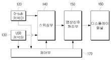
도 1에 도시된 바와 같이, 본 실시예에 따른 모니터는 DVI(Digital Visual Interface) 커넥터(110), USB(Universal Serial Bus) 커넥터(130), 스위칭부(140), 영상신호 처리부(150), 디스플레이 패널(160) 및 제어부(170)를 구비한다.As shown in FIG. 1, the monitor according to the present embodiment includes a DVI (Digital Visual Interface)
DVI 커넥터(110)는 DVI 케이블을 통해 PC(미도시)와 연결되며, PC로부터 DVI 규격의 영상신호를 입력받는다. DVI 커넥터(110)에는 여러 개의 핀들이 마련되어 있는데, 이 핀들 중 i) 일부는 PC에서 모니터로 클럭을 전달하는데 이용되고, ii) 다른 일부는 PC에서 모니터로 영상신호와 동기정보를 전달하는데 이용되며, iii) 나머지는 다른 용도로 이용된다.The
DVI 커넥터(110)는 디지털 영상신호를 입력받기 위한 'DVI-D 커넥터'와 디지털 영상신호 외에 아날로그 영상신호도 입력받을 수 있는 'DVI-I 커넥터'로 분류된다.The
도 2에는 DVI-I 커넥터를 도시하였다. 도시된 DVI-I 커넥터에 마련된 핀들 의 기능은 아래의 표와 같다.2 shows a DVI-I connector. The functions of the pins provided in the DVI-I connector shown are shown in the table below.
DVI-I 커넥터를 통해 디지털 영상신호를 입력받는데 이용될 수 있는 핀들은 1~5, 9~13, 17~21번 핀이며, 아날로그 영상신호를 입력받는데 이용되는 핀은 C1~C3번 핀이다. 한편, DVI-D 커넥터는 DVI-I 커넥터에서 C1~C5 핀을 제외한 핀들로 구성된다.Pins that can be used to receive digital video signals through the DVI-I connector are
USB 커넥터(130)는 USB 케이블을 통해 PC와 연결되며, PC로부터 USB 규격의 신호를 입력받는다. USB 커넥터(130)는 PC로부터 영상신호 외에 다른 신호도 입력받을 수도 있는 커넥터라는 점에서, PC로부터 영상신호를 입력받는데 이용되는 DVI 커넥터(110)와 차이가 있다. 즉, USB 커넥터(130)는 PC로부터 영상신호 이외에 음성신호, 텍스트신호 및 제어신호 등을 입력받는 경우에도 이용될 수 있다.The
또한, USB 커넥터(130)는 사용자 명령이 수록된 신호를 PC로 전송하는데 이용될 수도 있는 커넥터라는 점에서도, 사용자 명령이 수록된 신호를 PC로 전송하는데 이용될 수 없는 DVI 커넥터(110)와 차이가 있다. 여기서, 사용자 명령은 모니터에 연결된 키보드나 마우스와 같은 사용자 인터페이스 수단이나, 모니터 전면부 에 마련된 조작수단 등을 통해 모니터로 입력되며, USB 커넥터(130)를 통해 PC로 전달되게 된다.In addition, the
도 3에 도시된 바와 같이 USB 커넥터(130)는 4개의 핀(VBUS, D+, D-, GND 핀)들로 구성되는데, D+ 핀과 D- 핀은 PC와 모니터 간에 신호(영상신호와 동기정보, 음성신호, 텍스트신호, 제어신호 및 사용자 명령이 수록된 신호)를 전달하는데 이용된다.As shown in FIG. 3, the
이에 따르면, USB 커넥터(130)는 2개의 핀을 통해 PC로부터 영상신호와 동기정보를 입력받는 반면, DVI 커넥터(110)는 적어도 3개의 핀을 통해 PC로부터 영상신호와 동기정보를 입력받는다는 점에서도, 양자는 차이가 있다.According to this, the
스위칭부(140)는 DVI 커넥터(110)에 입력되는 영상신호와 USB 커넥터(130)에 입력되는 영상신호 중 하나가 후술할 영상신호 처리부(150)에 선택적으로 전달되도록 스위칭동작한다. 스위칭부(140)의 스위칭동작은 후술할 제어부(170)의 제어에 따른다.The
영상신호 처리부(150)는 스위칭부(140)에서 출력되는 영상신호에 대해 스케일링, 기타 필요한 신호처리를 수행한다.The
디스플레이 패널(160)은 영상신호 처리부(150)에서 신호처리된 영상신호에 대응하는 영상을 LCD(Liquid Crystal Display), CDT(Color Display Tube)와 같은 디스플레이에 표시하여, 사용자에게 제공한다.The
제어부(170)는 모니터의 전반적인 동작을 제어한다. 특히, 제어부(170)는 1) DVI 커넥터(110)에 PC가 연결되었는지 여부, 2) 연결되었다면 DVI 커넥터(110)에 영상신호가 입력되는지 여부, 3) USB 커넥터(130)에 PC가 연결되었는지 여부, 4) 연결되었다면 USB 커넥터(130)에 영상신호가 입력되는지 여부 등을 판단한다.The
그리고, 제어부(170)는 판단결과와 기설정된 '커넥터 우선순위'에 따라 스위칭부(140)의 스위칭동작을 제어하여. DVI 커넥터(110)에 입력되는 영상과 USB 커넥터(130)에 입력되는 영상 중 하나가 디스플레이되도록 한다.Then, the
여기서, '커넥터 우선순위'란, DVI 커넥터(110)와 USB 커넥터(130) 모두에 영상이 입력되는 경우, 어느 커넥터에 입력되는 영상을 우선적으로 디스플레이할지에 대한 지표이다. 부연하면, USB 커넥터(130)가 DVI 커넥터(110) 보다 우선순위가 높고 DVI 커넥터(110)와 USB 커넥터(130) 모두에 영상이 입력되는 경우에는, USB 커넥터(130)에 입력되는 영상이 디스플레이된다.Here, 'connector priority' is an indicator of which connector is preferentially displayed when an image is input to both the
한편, 모니터에 마련된 조작수단 중 선택버튼(미도시)을 통해, 사용자는 DVI 커넥터(110)에 입력되는 영상과 USB 커넥터(130)에 입력되는 영상 중 하나를 선택할 수 있다. 이 경우, 제어부(170)는 선택버튼을 통한 사용자의 선택에 부합하는 영상이 디스플레이되도록 스위칭부(140)의 스위칭동작을 제어한다.Meanwhile, the user may select one of an image input to the
도 4는 본 발명의 다른 실시예에 따른 모니터의 블럭도이다. 본 실시예에 따른 모니터 역시 다양한 커넥터들을 통해 PC로부터 영상을 입력받아 디스플레이할 수 있다.4 is a block diagram of a monitor according to another embodiment of the present invention. The monitor according to the present embodiment may also receive and display an image from a PC through various connectors.
도 4에 도시된 모니터는 DVI 커넥터(110) 대신 D-sub 커넥터(120)를 이용하여 구현하였다는 점에서, 도 1에 도시된 모니터와 차이가 있다.The monitor illustrated in FIG. 4 is different from the monitor illustrated in FIG. 1 in that the monitor illustrated in FIG. 4 is implemented using the D-
D-sub 커넥터(120)는 D-sub 케이블을 통해 PC(미도시)와 연결되며, PC로부터 D-sub 규격의 영상신호를 입력받는다. D-sub 커넥터(120)에는 여러 개의 핀들이 마련되어 있는데, 이 핀들 중 i) 일부는 PC에서 모니터로 동기신호를 전달하는데 이용되고, ii) 다른 일부는 PC에서 모니터로 영상신호를 전달하는데 이용되며, iii) 나머지는 다른 용도로 이용된다.The D-
도 5에는 D-sub 커넥터(120)를 도시하였다. 도시된 D-sub 커넥터(120)에 마련된 핀들의 기능은 아래의 표와 같다.5 shows the D-
D-sub 커넥터(120)를 통해 영상신호를 입력받는데 이용되는 핀들은 1~3, 6~8번 핀이다.Pins used to receive an image signal through the D-
USB 커넥터(130)는 USB 케이블을 통해 PC와 연결되며, PC로부터 USB 규격의 신호를 입력받는다. USB 커넥터(130)는 PC로부터 영상신호 외에 다른 신호도 입력받을 수도 있는 커넥터라는 점에서, PC로부터 영상신호를 입력받는데 이용되는 D-sub 커넥터(120)와 차이가 있다. 즉, USB 커넥터(130)는 PC로부터 영상신호 이외에 음성신호, 텍스트신호 및 제어신호 등을 입력받는 경우에도 이용될 수 있다.The
또한, USB 커넥터(130)는 사용자 명령이 수록된 신호를 PC로 전송하는데 이용될 수도 있는 커넥터라는 점에서도, 사용자 명령이 수록된 신호를 PC로 전송하는데 이용될 수 없는 D-sub 커넥터(120)와 차이가 있다.In addition, the
그리고, USB 커넥터(130)는 2개의 핀을 통해 PC로부터 영상신호와 동기정보를 입력받는 반면, DVI 커넥터(110)는 적어도 3개의 핀을 통해 PC로부터 영상신호를 입력받는다는 점에서도, 양자는 차이가 있다.The
스위칭부(140)는 D-sub 커넥터(120)에 입력되는 영상신호와 USB 커넥터(130)에 입력되는 영상신호 중 하나가 후술할 영상신호 처리부(150)에 선택적으로 전달되도록 스위칭동작한다. 스위칭부(140)의 스위칭동작은 후술할 제어부(170)의 제어에 따른다.The
영상신호 처리부(150)와 디스플레이 패널(160)은 도 1에 도시된 것과 동일하기에 상세한 설명은 생략한다.Since the
제어부(170)는 모니터의 전반적인 동작을 제어한다. 특히, 제어부(170)는 1) D-sub 커넥터(120)에 PC가 연결되었는지 여부, 2) 연결되었다면 D-sub 커넥터(120)에 영상신호가 입력되는지 여부, 3) USB 커넥터(130)에 PC가 연결되었는지 여부, 4) 연결되었다면 USB 커넥터(130)에 영상신호가 입력되는지 여부 등을 판단한다.The
그리고, 제어부(170)는 판단결과와 기설정된 '커넥터 우선순위'에 따라 스위칭부(140)의 스위칭동작을 제어하여. D-sub 커넥터(120)에 입력되는 영상과 USB 커넥터(130)에 입력되는 영상 중 하나가 디스플레이되도록 한다.Then, the
제어부(170)의 제어동작에 관한 구체적인 설명은 도 1에 도시된 제어부(170)의 설명으로 유추가능하기에, 이에 대한 상세한 설명은 생략한다.Since a detailed description of the control operation of the
도 6은 본 발명의 또 다른 실시예에 따른 모니터의 블럭도이다. 본 실시예 에 따른 모니터 역시 다양한 커넥터들을 통해 PC로부터 영상을 입력받아 디스플레이할 수 있다.6 is a block diagram of a monitor according to another embodiment of the present invention. The monitor according to the present embodiment may also receive and display an image from a PC through various connectors.
도 6에 도시된 모니터는 3가지 종류의 커넥터(DVI 커넥터(110), D-sub 커넥터(120), USB 커넥터(130))를 구비하였다는 점에서, 2가지 종류의 커넥터를 구비하고 있는 도 1과 도 4에 도시된 모니터들과 차이가 있다.The monitor shown in FIG. 6 is equipped with two types of connectors in that it is provided with three types of connectors (
도 6에 도시된 DVI 커넥터(110), D-sub 커넥터(120), USB 커넥터(130), 영상신호 처리부(150) 및 디스플레이 패널(160)에 대한 상세한 설명은, 도 1과 도 4에 도시된 DVI 커넥터(110), D-sub 커넥터(120), USB 커넥터(130), 영상신호 처리부(150) 및 디스플레이 패널(160)에 대한 상세한 설명과 일치하기에 생략하기로 한다.A detailed description of the
스위칭부(140)는 DVI 커넥터(110)에 입력되는 영상신호, D-sub 커넥터(120)에 입력되는 영상신호 및 USB 커넥터(130)에 입력되는 영상신호 중 하나가 영상신호 처리부(150)에 선택적으로 전달되도록 스위칭동작한다.The
제어부(170)는 모니터의 전반적인 동작을 제어한다. 특히, 제어부(170)는 스위칭부(140)의 스위칭동작을 제어하여. DVI 커넥터(110)에 입력되는 영상, D-sub 커넥터(120)에 입력되는 영상 및 USB 커넥터(130)에 입력되는 영상 중 하나가 디스플레이되도록 한다. 이하에서, 도 7을 참조하여 상세히 설명한다.The
도 7은 도 6에 도시된 모니터가 커넥터들에 입력되는 영상을 선택적으로 디스플레이하는 과정의 설명에 제공되는 흐름도이다. 도 7에서는 커넥터 우선순위가 USB 커넥터(130), DVI 커넥터(110) 및 D-sub 커넥터(120) 순으로 상정하였다.FIG. 7 is a flowchart provided to explain a process in which the monitor illustrated in FIG. 6 selectively displays an image input to connectors. In FIG. 7, the connector priority is assumed in order of the
도 7에 도시된 바와 같이, USB 케이블을 통해 USB 커넥터(130)에 PC가 연결되고(S210-Y), PC로부터 USB 커넥터(130)에 영상신호가 입력되는 것으로 판단되면(S215-Y), 제어부(170)는 USB 커넥터(130)에 입력되는 영상신호가 영상신호 처리부(150)로 전달되도록 스위칭부(140)의 스위칭동작을 제어한다(S220).As shown in FIG. 7, when the PC is connected to the
그러면, 영상신호 처리부(150)는 스위칭부(140)에서 출력되는 영상신호에 대해 스케일링 등의 신호처리를 수행하고(S225), 디스플레이 패널(160)은 영상신호 처리부(150)에서 신호처리된 영상신호에 대응하는 영상을 디스플레이한다(S230).Then, the
한편, USB 커넥터(130)에 PC가 연결되지 않았거나(S210-N), 연결되었더라도 PC로부터 USB 커넥터(130)에 영상신호가 입력되지 않으면(S215-N), 제어부(170)는 DVI 케이블을 통해 DVI 커넥터(110)에 PC가 연결되었는지 여부를 판단한다(S235).On the other hand, if the PC is not connected to the USB connector 130 (S210-N), or if the video signal is not input from the PC to the
DVI 케이블을 통해 DVI 커넥터(110)에 PC가 연결되고(S235-Y), PC로부터 DVI 커넥터(110)에 영상신호가 입력되는 것으로 판단되면(S240-Y), 제어부(170)는 DVI 커넥터(110)에 입력되는 영상신호가 영상신호 처리부(150)로 전달되도록 스위칭부(140)의 스위칭동작을 제어한다(S245). 이후, S225단계와 S230단계가 수행된다.When the PC is connected to the
한편, DVI 커넥터(110)에 PC가 연결되지 않았거나(S235-N), 연결되었더라도 PC로부터 DVI 커넥터(110)에 영상신호가 입력되지 않으면(S240-N), 제어부(170)는 D-sub 케이블을 통해 D-sub 커넥터(120)에 PC가 연결되었는지 여부를 판단한다(S250).On the other hand, if the PC is not connected to the DVI connector 110 (S235-N), or even if the video signal is not input from the PC to the DVI connector 110 (S240-N), the
D-sub 케이블을 통해 D-sub 커넥터(120)에 PC가 연결되고(S250-Y), PC로부터 D-sub 커넥터(120)에 영상신호가 입력되는 것으로 판단되면(S255-Y), 제어부(170) 는 D-sub 커넥터(120)에 입력되는 영상신호가 영상신호 처리부(150)로 전달되도록 스위칭부(140)의 스위칭동작을 제어한다(S260). 이후, S225단계와 S230단계가 수행된다.When the PC is connected to the D-
지금까지, DVI 커넥터, D-sub 커넥터 및 USB 커넥터를 선택적으로 구비하고, 이 커넥터들을 통해 입력되는 영상들 중 어느 하나를 디스플레이하는 모니터에 대해 바람직한 실시예들을 들어 상세히 설명하였다.Up to now, the present invention has been described in detail with reference to a preferred embodiment of a monitor that is optionally equipped with a DVI connector, a D-sub connector, and a USB connector and displays any one of images inputted through the connectors.
전술한 실시예들에서는 모니터에 DVI 커넥터, D-sub 커넥터 및 USB 커넥터가 선택적으로 구비되되, 구비되는 경우에는 하나만 구비되는 것으로 상정하였으나, 본 발명을 구현함에 있어서 반드시 이에 한정되는 것은 아니다. 따라서, DVI 커넥터, D-sub 커넥터 및 USB 커넥터가 각각 2개 이상씩 구비되는 경우에도 본 발명이 적용될 수 있음은 물론이다.In the above embodiments, a DVI connector, a D-sub connector, and a USB connector are selectively provided in the monitor, but it is assumed that only one is provided, but the present invention is not necessarily limited thereto. Therefore, the present invention can be applied to the case where two or more DVI connectors, D-sub connectors, and USB connectors are provided.
뿐만 아니라, 모니터에 전술한 DVI 커넥터, D-sub 커넥터 및 USB 커넥터 외에 다른 종류의 커넥터가 마련되는 경우에도, 본 발명의 기술적 사상이 적용될 수 있다. 다른 종류의 커넥터로서, 기존의 내부 인터페이스 표준인 LVDS(Low Voltage Differential Signaling)와 외부 연결 표준인 DVI를 통합하여 하나로 연결할 수 있는 방식의 커넥터인 '디스플레이 포트(Display Port) 커넥터'와, DVI, HDMI 등과 호환가능하며 HD 영상을 지원할 수 있는 방식의 커넥터인 'UDI(Unified Display Interface) 커넥터'를 들 수 있다.In addition, even if the monitor is provided with a connector other than the above-described DVI connector, D-sub connector and USB connector, the technical idea of the present invention can be applied. Another type of connector is the display port connector, which integrates the existing internal interface standard, Low Voltage Differential Signaling (LVDS) and external connection standard, DVI, and DVI, HDMI. The Unified Display Interface (UDI) connector is a connector that is compatible with and supports HD video.
또한, 전술한 실시예들에서는 PC로부터 입력되는 영상을 디스플레이하는 경우를 예로 들었으나, 이는 설명의 편의를 위해 든 예에 불과한 것으로서 PC가 아닌 다른 외부기기로부터 입력되는 영상을 디스플레이하는 경우에도 본 발명이 적용될 수 있음은 물론이다.In addition, in the above-described embodiments, a case of displaying an image input from a PC is taken as an example, but this is only an example for convenience of description and the case of displaying an image input from an external device other than a PC is provided. Of course this can be applied.
그리고, 전술한 실시예에서는 영상신호 처리부(150)와 제어부(170)가 별개의 블럭으로 구현되는 것으로 상정하였으나, 이들을 하나의 블럭으로 통합하여 구현하는 것도 가능함은 물론이다.In the above-described embodiment, it is assumed that the image
또한, 전술한 실시예들에서는 스위칭부(140)의 스위칭동작을 제어하여 다양한 커넥터들을 통해 입력되는 영상들 중 하나가 선택적으로 디스플레이되도록 구현하였으나, 이 역시 이해의 편의를 위해 든 예에 불과한 것이다. 따라서, 스위칭부(140)를 이용하지 않고, 영상신호 처리부(150)가 다양한 커넥터들을 통해 입력되는 영상신호들 중 하나를 선택적으로 신호처리하도록 구현하는 것도 가능함은 물론이다.In addition, in the above-described embodiments, the switching operation of the
그리고, 모니터는 디스플레이 장치의 일종이며, 본 발명은 모니터가 아닌 다른 종류의 디스플레이 장치에도 적용될 수 있다.The monitor is a type of display device, and the present invention can be applied to other types of display devices other than the monitor.
한편, 도 7에서는 커넥터 우선순위를 USB 커넥터(130), DVI 커넥터(110) 및 D-sub 커넥터(120) 순으로 상정하였으나, 커넥터 우선순위는 이와 다르게 정해질 수도 있음은 물론이다.Meanwhile, in FIG. 7, the connector priority is assumed in order of the
이상 설명한 바와 같이, 본 발명에 따르면, DVI 커넥터와 D-sub 커넥터 외에 USB 커넥터를 통해 PC와 같은 외부기기로부터 영상을 수신받아 디스플레이할 수 있게 된다. 이에 따라, 별도의 하드웨어 추가 없이도, DVI 커넥터와 D-sub 커넥터의 개수 보다 더 많은 개수의 디스플레이 장치를 PC에 연결할 수 있게 된다. 뿐만 아니라, DVI 케이블이나 D-sub 케이블 보다 라인 수가 적어 가격이 저렴한 USB 케이블을 이용하여 PC와 디스플레이 장치를 연결할 수 있게 되는 효과도 이룰 수 있게 된다.As described above, according to the present invention, it is possible to receive and display an image from an external device such as a PC through the USB connector in addition to the DVI connector and the D-sub connector. Accordingly, a larger number of display devices can be connected to the PC than the number of DVI connectors and D-sub connectors without additional hardware. In addition, the number of lines is lower than that of a DVI cable or a D-sub cable, which makes it possible to connect a PC to a display device using an inexpensive USB cable.
또한, 이상에서는 본 발명의 바람직한 실시예에 대하여 도시하고 설명하였지만, 본 발명은 상술한 특정의 실시예에 한정되지 아니하며, 청구범위에서 청구하는 본 발명의 요지를 벗어남이 없이 당해 발명이 속하는 기술분야에서 통상의 지식을 가진자에 의해 다양한 변형실시가 가능한 것은 물론이고, 이러한 변형실시들은 본 발명의 기술적 사상이나 전망으로부터 개별적으로 이해되어져서는 안될 것이다.In addition, although the preferred embodiment of the present invention has been shown and described above, the present invention is not limited to the specific embodiments described above, but the technical field to which the invention belongs without departing from the spirit of the invention claimed in the claims. Of course, various modifications can be made by those skilled in the art, and these modifications should not be individually understood from the technical spirit or the prospect of the present invention.
Claims (11)
Translated fromKoreanPriority Applications (4)
| Application Number | Priority Date | Filing Date | Title |
|---|---|---|---|
| KR1020070001614AKR20080064568A (en) | 2007-01-05 | 2007-01-05 | Display device that displays video input through various connectors |
| US11/960,846US20080165291A1 (en) | 2007-01-05 | 2007-12-20 | Display apparatus for displaying video input through various connectors |
| EP07124118AEP1942486A3 (en) | 2007-01-05 | 2007-12-28 | Display apparatus for displaying video input through various connectors |
| CN2008100951482ACN101261824B (en) | 2007-01-05 | 2008-01-04 | Display device for displaying video inputted through various connectors |
Applications Claiming Priority (1)
| Application Number | Priority Date | Filing Date | Title |
|---|---|---|---|
| KR1020070001614AKR20080064568A (en) | 2007-01-05 | 2007-01-05 | Display device that displays video input through various connectors |
Publications (1)
| Publication Number | Publication Date |
|---|---|
| KR20080064568Atrue KR20080064568A (en) | 2008-07-09 |
Family
ID=39156302
Family Applications (1)
| Application Number | Title | Priority Date | Filing Date |
|---|---|---|---|
| KR1020070001614ACeasedKR20080064568A (en) | 2007-01-05 | 2007-01-05 | Display device that displays video input through various connectors |
Country Status (4)
| Country | Link |
|---|---|
| US (1) | US20080165291A1 (en) |
| EP (1) | EP1942486A3 (en) |
| KR (1) | KR20080064568A (en) |
| CN (1) | CN101261824B (en) |
Cited By (2)
| Publication number | Priority date | Publication date | Assignee | Title |
|---|---|---|---|---|
| KR101232057B1 (en)* | 2011-02-28 | 2013-03-11 | 스마트파이 주식회사 | Dual Mode Receiver |
| US8539258B2 (en) | 2009-04-24 | 2013-09-17 | Samsung Electronics Co., Ltd. | Mobile electronic device having content transmission interface |
Families Citing this family (10)
| Publication number | Priority date | Publication date | Assignee | Title |
|---|---|---|---|---|
| BR0315624A (en) | 2002-10-22 | 2005-08-23 | Jason A Sullivan | Rugged Customizable Computer Processing System |
| AU2003285949A1 (en)* | 2002-10-22 | 2004-05-13 | Isys Technologies | Non-peripherals processing control module having improved heat dissipating properties |
| BR0315613A (en) | 2002-10-22 | 2005-08-23 | Jason A Sullivan | Systems and methods for providing a dynamically modular processing unit |
| US7990724B2 (en) | 2006-12-19 | 2011-08-02 | Juhasz Paul R | Mobile motherboard |
| JP5608980B2 (en)* | 2009-01-27 | 2014-10-22 | セイコーエプソン株式会社 | Document camera and image display system |
| CN102264190A (en)* | 2010-05-31 | 2011-11-30 | 鸿富锦精密工业(深圳)有限公司 | A printed circuit board |
| US20110302357A1 (en)* | 2010-06-07 | 2011-12-08 | Sullivan Jason A | Systems and methods for dynamic multi-link compilation partitioning |
| KR20130076132A (en)* | 2011-12-28 | 2013-07-08 | 삼성전자주식회사 | Display apparatus and method for displaying of image |
| KR20150010872A (en)* | 2013-07-19 | 2015-01-29 | 삼성전자주식회사 | Display apparatus and Method for providing user interface thereof |
| JP6801003B2 (en) | 2016-01-18 | 2020-12-16 | ウェーヴシフト・エルエルシー | Evaluation and reduction of myopia generation effect of electronic display |
Family Cites Families (8)
| Publication number | Priority date | Publication date | Assignee | Title |
|---|---|---|---|---|
| JP2002171449A (en)* | 2000-11-30 | 2002-06-14 | Sony Corp | Display device and method, and recording medium |
| US6904341B2 (en)* | 2002-06-12 | 2005-06-07 | Sea-Watch Technologies, Inc. | Integrated vessel monitoring and control system |
| KR100449739B1 (en)* | 2002-09-19 | 2004-09-22 | 삼성전자주식회사 | Display device and method for checking input signal |
| US20070097020A1 (en)* | 2003-08-27 | 2007-05-03 | Yoshifumi Sato | Display device |
| US20050134746A1 (en)* | 2003-12-18 | 2005-06-23 | Brandt Nicholas C. | Controllable video switching method and apparatus |
| CN1851797A (en)* | 2005-04-22 | 2006-10-25 | 鸿富锦精密工业(深圳)有限公司 | Signal adapting device |
| TWI384870B (en)* | 2006-01-03 | 2013-02-01 | Mstar Semiconductor Inc | Method of auto-switching audio-video signals and associated apparatus |
| US20070298656A1 (en)* | 2006-06-22 | 2007-12-27 | Good Mind Industries Co., Ltd. | Switch apparatus for multiple high definition multimedia interface sources |
- 2007
- 2007-01-05KRKR1020070001614Apatent/KR20080064568A/ennot_activeCeased
- 2007-12-20USUS11/960,846patent/US20080165291A1/ennot_activeAbandoned
- 2007-12-28EPEP07124118Apatent/EP1942486A3/ennot_activeCeased
- 2008
- 2008-01-04CNCN2008100951482Apatent/CN101261824B/ennot_activeExpired - Fee Related
Cited By (3)
| Publication number | Priority date | Publication date | Assignee | Title |
|---|---|---|---|---|
| US8539258B2 (en) | 2009-04-24 | 2013-09-17 | Samsung Electronics Co., Ltd. | Mobile electronic device having content transmission interface |
| USRE45995E1 (en) | 2009-04-24 | 2016-05-03 | Samsung Electronics Co., Ltd. | Mobile electronic device having content transmission interface |
| KR101232057B1 (en)* | 2011-02-28 | 2013-03-11 | 스마트파이 주식회사 | Dual Mode Receiver |
Also Published As
| Publication number | Publication date |
|---|---|
| US20080165291A1 (en) | 2008-07-10 |
| EP1942486A2 (en) | 2008-07-09 |
| CN101261824A (en) | 2008-09-10 |
| CN101261824B (en) | 2012-04-18 |
| EP1942486A3 (en) | 2009-05-06 |
Similar Documents
| Publication | Publication Date | Title |
|---|---|---|
| KR20080064568A (en) | Display device that displays video input through various connectors | |
| US7536483B2 (en) | Computer system having analog and digital video signal output functionality, and computer device and video signal transmitting device thereof | |
| US7123248B1 (en) | Analog multi-display using digital visual interface | |
| KR100667748B1 (en) | Display recognition information output device and method according to connector type | |
| CN102054469A (en) | Display and display method thereof | |
| US8176228B2 (en) | Quick port-switching method and associated apparatus | |
| KR20030054654A (en) | Lcd module with an integrated connector and lcd device having the same | |
| US10866915B2 (en) | Method for increasing the compatibility of displayport | |
| CN107665105A (en) | Display device interfaces conversion equipment, Multi-screen display system and multi-display method | |
| KR20100033199A (en) | Liquid crystal display and display system comprising the same | |
| KR100749811B1 (en) | Display device and control method | |
| KR20090057789A (en) | Liquid crystal display and display system including same | |
| KR20090081662A (en) | Connector and Display with It | |
| KR20090058359A (en) | Liquid crystal panel display device and method | |
| KR102212208B1 (en) | Data Driving Circuit Device for Display Device and Display Device having the same | |
| US20110310070A1 (en) | Image splitting in a multi-monitor system | |
| CN107529025A (en) | A kind of display with picture segmentation display function | |
| US10659727B2 (en) | Device and method for transmitting video signals, and system for playing video signals | |
| EP1845589B1 (en) | Computer system having analog and digital video signal output functionality, and computer device and video signal transmitting device thereof | |
| KR100471057B1 (en) | portable computer and method for reproducing video signal on screen thereof | |
| KR20150085723A (en) | A method for synchronizing auxiliary signal | |
| CN102695023A (en) | Video signal processing system and method | |
| CN103428443A (en) | Video channel control system and video channel control method | |
| CN1897671A (en) | Synchronous-outputting interface module of video-signal multi-display equipment | |
| CN208224904U (en) | A kind of medical display of automatic fault detection |
Legal Events
| Date | Code | Title | Description |
|---|---|---|---|
| PA0109 | Patent application | Patent event code:PA01091R01D Comment text:Patent Application Patent event date:20070105 | |
| PG1501 | Laying open of application | ||
| A201 | Request for examination | ||
| PA0201 | Request for examination | Patent event code:PA02012R01D Patent event date:20120105 Comment text:Request for Examination of Application Patent event code:PA02011R01I Patent event date:20070105 Comment text:Patent Application | |
| PE0902 | Notice of grounds for rejection | Comment text:Notification of reason for refusal Patent event date:20130328 Patent event code:PE09021S01D | |
| E601 | Decision to refuse application | ||
| PE0601 | Decision on rejection of patent | Patent event date:20130716 Comment text:Decision to Refuse Application Patent event code:PE06012S01D Patent event date:20130328 Comment text:Notification of reason for refusal Patent event code:PE06011S01I |