KR20080056754A - Axial Flow Pumps with Multiple Groove Rotors - Google Patents
Axial Flow Pumps with Multiple Groove RotorsDownload PDFInfo
- Publication number
- KR20080056754A KR20080056754AKR1020087010400AKR20087010400AKR20080056754AKR 20080056754 AKR20080056754 AKR 20080056754AKR 1020087010400 AKR1020087010400 AKR 1020087010400AKR 20087010400 AKR20087010400 AKR 20087010400AKR 20080056754 AKR20080056754 AKR 20080056754A
- Authority
- KR
- South Korea
- Prior art keywords
- rotor
- blood
- pump
- blood pump
- housing
- Prior art date
- Legal status (The legal status is an assumption and is not a legal conclusion. Google has not performed a legal analysis and makes no representation as to the accuracy of the status listed.)
- Granted
Links
Images


Classifications
- A—HUMAN NECESSITIES
- A61—MEDICAL OR VETERINARY SCIENCE; HYGIENE
- A61M—DEVICES FOR INTRODUCING MEDIA INTO, OR ONTO, THE BODY; DEVICES FOR TRANSDUCING BODY MEDIA OR FOR TAKING MEDIA FROM THE BODY; DEVICES FOR PRODUCING OR ENDING SLEEP OR STUPOR
- A61M60/00—Blood pumps; Devices for mechanical circulatory actuation; Balloon pumps for circulatory assistance
- A61M60/10—Location thereof with respect to the patient's body
- A61M60/122—Implantable pumps or pumping devices, i.e. the blood being pumped inside the patient's body
- A—HUMAN NECESSITIES
- A61—MEDICAL OR VETERINARY SCIENCE; HYGIENE
- A61M—DEVICES FOR INTRODUCING MEDIA INTO, OR ONTO, THE BODY; DEVICES FOR TRANSDUCING BODY MEDIA OR FOR TAKING MEDIA FROM THE BODY; DEVICES FOR PRODUCING OR ENDING SLEEP OR STUPOR
- A61M60/00—Blood pumps; Devices for mechanical circulatory actuation; Balloon pumps for circulatory assistance
- A61M60/40—Details relating to driving
- A61M60/403—Details relating to driving for non-positive displacement blood pumps
- A61M60/419—Details relating to driving for non-positive displacement blood pumps the force acting on the blood contacting member being permanent magnetic, e.g. from a rotating magnetic coupling between driving and driven magnets
- A—HUMAN NECESSITIES
- A61—MEDICAL OR VETERINARY SCIENCE; HYGIENE
- A61M—DEVICES FOR INTRODUCING MEDIA INTO, OR ONTO, THE BODY; DEVICES FOR TRANSDUCING BODY MEDIA OR FOR TAKING MEDIA FROM THE BODY; DEVICES FOR PRODUCING OR ENDING SLEEP OR STUPOR
- A61M60/00—Blood pumps; Devices for mechanical circulatory actuation; Balloon pumps for circulatory assistance
- A61M60/10—Location thereof with respect to the patient's body
- A61M60/122—Implantable pumps or pumping devices, i.e. the blood being pumped inside the patient's body
- A61M60/126—Implantable pumps or pumping devices, i.e. the blood being pumped inside the patient's body implantable via, into, inside, in line, branching on, or around a blood vessel
- A61M60/148—Implantable pumps or pumping devices, i.e. the blood being pumped inside the patient's body implantable via, into, inside, in line, branching on, or around a blood vessel in line with a blood vessel using resection or like techniques, e.g. permanent endovascular heart assist devices
- A—HUMAN NECESSITIES
- A61—MEDICAL OR VETERINARY SCIENCE; HYGIENE
- A61M—DEVICES FOR INTRODUCING MEDIA INTO, OR ONTO, THE BODY; DEVICES FOR TRANSDUCING BODY MEDIA OR FOR TAKING MEDIA FROM THE BODY; DEVICES FOR PRODUCING OR ENDING SLEEP OR STUPOR
- A61M60/00—Blood pumps; Devices for mechanical circulatory actuation; Balloon pumps for circulatory assistance
- A61M60/10—Location thereof with respect to the patient's body
- A61M60/122—Implantable pumps or pumping devices, i.e. the blood being pumped inside the patient's body
- A61M60/165—Implantable pumps or pumping devices, i.e. the blood being pumped inside the patient's body implantable in, on, or around the heart
- A61M60/178—Implantable pumps or pumping devices, i.e. the blood being pumped inside the patient's body implantable in, on, or around the heart drawing blood from a ventricle and returning the blood to the arterial system via a cannula external to the ventricle, e.g. left or right ventricular assist devices
- A—HUMAN NECESSITIES
- A61—MEDICAL OR VETERINARY SCIENCE; HYGIENE
- A61M—DEVICES FOR INTRODUCING MEDIA INTO, OR ONTO, THE BODY; DEVICES FOR TRANSDUCING BODY MEDIA OR FOR TAKING MEDIA FROM THE BODY; DEVICES FOR PRODUCING OR ENDING SLEEP OR STUPOR
- A61M60/00—Blood pumps; Devices for mechanical circulatory actuation; Balloon pumps for circulatory assistance
- A61M60/10—Location thereof with respect to the patient's body
- A61M60/122—Implantable pumps or pumping devices, i.e. the blood being pumped inside the patient's body
- A61M60/196—Implantable pumps or pumping devices, i.e. the blood being pumped inside the patient's body replacing the entire heart, e.g. total artificial hearts [TAH]
- A—HUMAN NECESSITIES
- A61—MEDICAL OR VETERINARY SCIENCE; HYGIENE
- A61M—DEVICES FOR INTRODUCING MEDIA INTO, OR ONTO, THE BODY; DEVICES FOR TRANSDUCING BODY MEDIA OR FOR TAKING MEDIA FROM THE BODY; DEVICES FOR PRODUCING OR ENDING SLEEP OR STUPOR
- A61M60/00—Blood pumps; Devices for mechanical circulatory actuation; Balloon pumps for circulatory assistance
- A61M60/20—Type thereof
- A61M60/205—Non-positive displacement blood pumps
- A61M60/216—Non-positive displacement blood pumps including a rotating member acting on the blood, e.g. impeller
- A61M60/221—Non-positive displacement blood pumps including a rotating member acting on the blood, e.g. impeller the blood flow through the rotating member having both radial and axial components, e.g. mixed flow pumps
- A—HUMAN NECESSITIES
- A61—MEDICAL OR VETERINARY SCIENCE; HYGIENE
- A61M—DEVICES FOR INTRODUCING MEDIA INTO, OR ONTO, THE BODY; DEVICES FOR TRANSDUCING BODY MEDIA OR FOR TAKING MEDIA FROM THE BODY; DEVICES FOR PRODUCING OR ENDING SLEEP OR STUPOR
- A61M60/00—Blood pumps; Devices for mechanical circulatory actuation; Balloon pumps for circulatory assistance
- A61M60/20—Type thereof
- A61M60/205—Non-positive displacement blood pumps
- A61M60/216—Non-positive displacement blood pumps including a rotating member acting on the blood, e.g. impeller
- A61M60/226—Non-positive displacement blood pumps including a rotating member acting on the blood, e.g. impeller the blood flow through the rotating member having mainly radial components
- A61M60/232—Centrifugal pumps
- A—HUMAN NECESSITIES
- A61—MEDICAL OR VETERINARY SCIENCE; HYGIENE
- A61M—DEVICES FOR INTRODUCING MEDIA INTO, OR ONTO, THE BODY; DEVICES FOR TRANSDUCING BODY MEDIA OR FOR TAKING MEDIA FROM THE BODY; DEVICES FOR PRODUCING OR ENDING SLEEP OR STUPOR
- A61M60/00—Blood pumps; Devices for mechanical circulatory actuation; Balloon pumps for circulatory assistance
- A61M60/20—Type thereof
- A61M60/205—Non-positive displacement blood pumps
- A61M60/216—Non-positive displacement blood pumps including a rotating member acting on the blood, e.g. impeller
- A61M60/237—Non-positive displacement blood pumps including a rotating member acting on the blood, e.g. impeller the blood flow through the rotating member having mainly axial components, e.g. axial flow pumps
- A—HUMAN NECESSITIES
- A61—MEDICAL OR VETERINARY SCIENCE; HYGIENE
- A61M—DEVICES FOR INTRODUCING MEDIA INTO, OR ONTO, THE BODY; DEVICES FOR TRANSDUCING BODY MEDIA OR FOR TAKING MEDIA FROM THE BODY; DEVICES FOR PRODUCING OR ENDING SLEEP OR STUPOR
- A61M60/00—Blood pumps; Devices for mechanical circulatory actuation; Balloon pumps for circulatory assistance
- A61M60/40—Details relating to driving
- A61M60/403—Details relating to driving for non-positive displacement blood pumps
- A61M60/422—Details relating to driving for non-positive displacement blood pumps the force acting on the blood contacting member being electromagnetic, e.g. using canned motor pumps
- A—HUMAN NECESSITIES
- A61—MEDICAL OR VETERINARY SCIENCE; HYGIENE
- A61M—DEVICES FOR INTRODUCING MEDIA INTO, OR ONTO, THE BODY; DEVICES FOR TRANSDUCING BODY MEDIA OR FOR TAKING MEDIA FROM THE BODY; DEVICES FOR PRODUCING OR ENDING SLEEP OR STUPOR
- A61M60/00—Blood pumps; Devices for mechanical circulatory actuation; Balloon pumps for circulatory assistance
- A61M60/50—Details relating to control
- A61M60/508—Electronic control means, e.g. for feedback regulation
- A—HUMAN NECESSITIES
- A61—MEDICAL OR VETERINARY SCIENCE; HYGIENE
- A61M—DEVICES FOR INTRODUCING MEDIA INTO, OR ONTO, THE BODY; DEVICES FOR TRANSDUCING BODY MEDIA OR FOR TAKING MEDIA FROM THE BODY; DEVICES FOR PRODUCING OR ENDING SLEEP OR STUPOR
- A61M60/00—Blood pumps; Devices for mechanical circulatory actuation; Balloon pumps for circulatory assistance
- A61M60/80—Constructional details other than related to driving
- A61M60/802—Constructional details other than related to driving of non-positive displacement blood pumps
- A61M60/804—Impellers
- A61M60/806—Vanes or blades
- A—HUMAN NECESSITIES
- A61—MEDICAL OR VETERINARY SCIENCE; HYGIENE
- A61M—DEVICES FOR INTRODUCING MEDIA INTO, OR ONTO, THE BODY; DEVICES FOR TRANSDUCING BODY MEDIA OR FOR TAKING MEDIA FROM THE BODY; DEVICES FOR PRODUCING OR ENDING SLEEP OR STUPOR
- A61M60/00—Blood pumps; Devices for mechanical circulatory actuation; Balloon pumps for circulatory assistance
- A61M60/80—Constructional details other than related to driving
- A61M60/802—Constructional details other than related to driving of non-positive displacement blood pumps
- A61M60/81—Pump housings
- A—HUMAN NECESSITIES
- A61—MEDICAL OR VETERINARY SCIENCE; HYGIENE
- A61M—DEVICES FOR INTRODUCING MEDIA INTO, OR ONTO, THE BODY; DEVICES FOR TRANSDUCING BODY MEDIA OR FOR TAKING MEDIA FROM THE BODY; DEVICES FOR PRODUCING OR ENDING SLEEP OR STUPOR
- A61M60/00—Blood pumps; Devices for mechanical circulatory actuation; Balloon pumps for circulatory assistance
- A61M60/80—Constructional details other than related to driving
- A61M60/802—Constructional details other than related to driving of non-positive displacement blood pumps
- A61M60/818—Bearings
- A61M60/82—Magnetic bearings
- A—HUMAN NECESSITIES
- A61—MEDICAL OR VETERINARY SCIENCE; HYGIENE
- A61M—DEVICES FOR INTRODUCING MEDIA INTO, OR ONTO, THE BODY; DEVICES FOR TRANSDUCING BODY MEDIA OR FOR TAKING MEDIA FROM THE BODY; DEVICES FOR PRODUCING OR ENDING SLEEP OR STUPOR
- A61M60/00—Blood pumps; Devices for mechanical circulatory actuation; Balloon pumps for circulatory assistance
- A61M60/80—Constructional details other than related to driving
- A61M60/802—Constructional details other than related to driving of non-positive displacement blood pumps
- A61M60/818—Bearings
- A61M60/824—Hydrodynamic or fluid film bearings
- F—MECHANICAL ENGINEERING; LIGHTING; HEATING; WEAPONS; BLASTING
- F04—POSITIVE - DISPLACEMENT MACHINES FOR LIQUIDS; PUMPS FOR LIQUIDS OR ELASTIC FLUIDS
- F04D—NON-POSITIVE-DISPLACEMENT PUMPS
- F04D29/00—Details, component parts, or accessories
- F04D29/04—Shafts or bearings, or assemblies thereof
- F04D29/046—Bearings
- F04D29/047—Bearings hydrostatic; hydrodynamic
- F04D29/0476—Bearings hydrostatic; hydrodynamic for axial pumps
- F—MECHANICAL ENGINEERING; LIGHTING; HEATING; WEAPONS; BLASTING
- F04—POSITIVE - DISPLACEMENT MACHINES FOR LIQUIDS; PUMPS FOR LIQUIDS OR ELASTIC FLUIDS
- F04D—NON-POSITIVE-DISPLACEMENT PUMPS
- F04D3/00—Axial-flow pumps
- F04D3/02—Axial-flow pumps of screw type
Landscapes
- Health & Medical Sciences (AREA)
- Engineering & Computer Science (AREA)
- Heart & Thoracic Surgery (AREA)
- Cardiology (AREA)
- Mechanical Engineering (AREA)
- Life Sciences & Earth Sciences (AREA)
- Veterinary Medicine (AREA)
- Hematology (AREA)
- Anesthesiology (AREA)
- Animal Behavior & Ethology (AREA)
- General Health & Medical Sciences (AREA)
- Public Health (AREA)
- Biomedical Technology (AREA)
- Physics & Mathematics (AREA)
- Fluid Mechanics (AREA)
- General Engineering & Computer Science (AREA)
- Vascular Medicine (AREA)
- External Artificial Organs (AREA)
- Structures Of Non-Positive Displacement Pumps (AREA)
Abstract
Translated fromKoreanDescription
Translated fromKorean본 발명은 회전 펌프에 관한 것으로, 특히 일단부에 혈액입구와 타단부에 혈액 출구를 갖는 대응하는 원통형 하우징 내에서 부상(浮上)하는 실질적으로 원통형인 회전자와, 회전 에너지를 제공하여 회전자를 회전시키고 하우징 입구로부터 하우징 출구까지 하우징을 통해서 길이방향으로 혈액 유체를 펌핑하는 모터 부품을 갖는 축류 혈액 펌프에 관한 것이다.TECHNICAL FIELD The present invention relates to a rotary pump, in particular a substantially cylindrical rotor that floats in a corresponding cylindrical housing having a blood inlet at one end and a blood outlet at the other end, and providing a rotational energy to provide the rotor energy. An axial blood pump having a motor part that rotates and pumps blood fluid longitudinally through the housing from the housing inlet to the housing outlet.
공지의 혈액용 축류 펌프는 원심 유동 펌프와 비교하여, 좁은 반경 방향 폭을 갖는 이점이 있다. 따라서, 축류 펌프는 혈관내 또는 심장내 혈액 펌핑 보조용으로 사용할 수 있다. 축류 펌프는 전형적으로 일단부에 입구와 타단부에 출구를 갖는 원통형 하우징과, 하우징 내의 회전자를 갖는다. 회전자는, 해당 회전자에 부착되고 그로부터 반경 방향 외측으로 돌출되는 얇은 임펠러 블레이드 또는 베인을 갖는다. 그러므로, 회전자가 회전함에 따라서, 블레이드는 유체에 일을 가해서 하우징 입구로부터 하우징 출구까지 하우징을 통해서 유체를 추진시킨다.Known blood axial pumps have the advantage of having a narrow radial width compared to centrifugal flow pumps. Thus, the axial pump can be used for intravascular or intracardiac blood pumping assistance. Axial pumps typically have a cylindrical housing having an inlet at one end and an outlet at the other end, and a rotor in the housing. The rotor has a thin impeller blade or vane attached to the rotor and projecting radially outward therefrom. Therefore, as the rotor rotates, the blades apply fluid to the fluid and propel the fluid through the housing from the housing inlet to the housing outlet.
회전자를 하우징 내의 원하는 위치에 유지시키는 부상 시스템(suspension system)이 제공되며, 회전자의 회전을 위해서 전자기 모터가 제공된다. 회전자는 혈액 유동 통로 내에서 기계적, 자기적 또는 유체 역학적으로 부상될 수 있다. 그러한 부상 기술을 조합해서 이용할 수 있다.Suspension systems are provided for maintaining the rotor in a desired position within the housing, and an electromagnetic motor is provided for rotation of the rotor. The rotor may be mechanically, magnetically or hydrodynamically floated in the blood flow passage. Such injury techniques can be used in combination.
전형적으로 종래 기술에 있어서, 회전자는 베어링이나 부싱, 일부는 펌프 하우징을 통해서 모터 구동 기구까지 돌출하는 회전자 축에 의해서 부상한다. 자기 부상은 미국특허 제6,368,083호 및 제5,840,070호에도 공지되어 있다. 펌프로부터 배출된 혈액은 회전자의 회전축과 평행하게 유동한다.Typically in the prior art, the rotor is floated by a bearing or bushing, part of the rotor shaft which projects through the pump housing to the motor drive mechanism. Maglev is also known from US Pat. Nos. 6,368,083 and 5,840,070. Blood discharged from the pump flows parallel to the axis of rotation of the rotor.
지금까지의 축류 혈액 펌프는 자르빅(Jarvik) 및 인코(Incor)에 의한 펌프에서와 같이, 주변 고정자로부터 비교적 멀리 떨어진 회전자 축 내에 놓이는 모터 자석을 갖는 얇은 블레이드 설계를 이용해 왔거나, 또는 마크로메드(MicroMed)사에 의해 제조된 펌프에서와 같이, 이들 펌프는 얇은 블레이드 내에 배치된 작은 자석을 이용한다. 이러한 접근은 모두 모터의 토크 용량과 효율을 감소시키는 경향이 있으며, 이들은 회전시 서로 움직이면서 마모되는 인접면을 갖는 기구적인 회전자 지지부를 필요로 한다.To date, axial flow pumps have used thin blade designs with motor magnets that lie in the rotor shaft relatively far from the peripheral stator, such as those from Jarvik and Incor, or Macromed As with the pumps made by MicroMed, these pumps use small magnets placed in thin blades. All of these approaches tend to reduce the torque capacity and efficiency of the motor, which requires mechanical rotor supports with adjacent surfaces that wear out as they move with each other as they rotate.
혈액 펌프가 내부 또는 외부의 어느 곳에 위치하든지 이전의 얇은 블레이드 설계보다 유동 변동에 대해 보다 내성이 있고, 낮은 혈구파괴, 혈전병에 대한 우수한 저항력, 적절한 시스템 효율 및 디바이스에 대한 예상 사용 기간 동안 매우 높은 신뢰성을 보이는 것이 바람직하다. 또한, 초기에 배치한 혈액 펌프는 해부학적 상용성 설계에 제약을 받으며, 성공적이고 장기간 사용이 가능하며 이식가능한 디바이스를 제공하기 위해서 기계적인 마모 및 관련 실패 모드를 제거할 필요가 있다.Wherever the blood pump is located, internally or externally, it is more resistant to flow fluctuations than previous thin blade designs, and has very high blood counts, good resistance to thrombosis, adequate system efficiency and very high expected lifetimes for the device. It is desirable to show reliability. In addition, initially placed blood pumps are constrained by anatomical compatibility designs and need to eliminate mechanical wear and associated failure modes to provide a successful, long-term, and implantable device.
본 발명의 펌프를 혈액 펌프에 관해서 기술하지만, 화학적으로 취급이 어려운 유체나 비자성 유체를 펌핑하는 데 사용되는 펌프도 생각할 수 있으며, 이 경우 무봉인(sealless) 설계가 매우 바람직하다. 가령, 분해 및 폭발까지도 일으키는 기계적인 응력의 불안정 때문에, 또는 이것이 임계 안정성 파라미터를 갖는 혈액 이외에 다른 합성 체액이기 때문에, 유체는 여러 가지 이유에서 적절히 취급해야 한다.Although the pump of the present invention is described with reference to a blood pump, a pump used for pumping a fluid or a nonmagnetic fluid which is difficult to handle chemically can also be considered, in which case a sealless design is highly desirable. Fluids must be handled appropriately for a variety of reasons, for example because of the unstable mechanical stress that causes decomposition and explosion, or because it is a synthetic fluid other than blood having a critical stability parameter.
본 발명에 따르면, 개방된 일단부에 혈액입구 및 개방된 타단부에 혈액출구를 갖는 관상(管狀)의 펌프 하우징을 포함하는 축류 무봉인 및 무마모(wearless) 혈액 펌프가 제공된다. 원통형 회전자는 하우징 튜브 내에서 부상한다. 회전자는 압력을 유도 및 생성하여 입구 단부로부터 출구 단부까지 하우징을 통한 혈액의 운동을 돕는 다수의 원주면 및 반경면을 포함한다. 모터는 하우징 내에서 회전자를 회전시키기 위해 제공된다. 일 실시예에 있어서, 모터 고정자는 하우징 튜브의 외측이나 내부에 배치된 전도성 코일을 구비한다. 회전자 상에는 그의 외주면에 대해 이격된 다수의 모터 구동용 자극이 배치된다. 고정자 코일은 자속을 제공하여 회전자를 회전시킨다.According to the present invention, there is provided an axially sealed and wearless blood pump comprising a tubular pump housing having a blood inlet at an open end and a blood outlet at the other open end. The cylindrical rotor floats in the housing tube. The rotor includes a plurality of circumferential and radial surfaces that induce and generate pressure to assist the movement of blood through the housing from the inlet end to the outlet end. A motor is provided to rotate the rotor in the housing. In one embodiment, the motor stator has a conductive coil disposed outside or inside the housing tube. On the rotor are arranged a plurality of motor drive poles spaced apart from their outer circumferential surface. The stator coils provide magnetic flux to rotate the rotor.
회전자는 입구에서 하우징으로 유입되는 혈액을 수용하기 위한 전단부와 하우징의 출구에서 혈액의 배출을 증진시키기 위한 후단부를 갖는 원통체를 포함한다. 회전자는, 이 회전자 전단부의 유입채널부터 후단부의 배출채널까지 각기 연장되어 회전자의 표면 상에서 그들 사이에 다수의 활형상의 외주 랜드 영역을 제공하는 하나 이상의 홈을 포함한다. 각 홈을 제공하는 측벽면은 회전자 표면까지 반경 방향으로 연장되지만, 서로 평행할 필요는 없다. 일부 실시예에 있어서, 각 홈은 회전자의 회전축 둘레에서 적어도 부분적으로 만곡된 유동채널을 제공하고 회전자의 후단부에서 실질적으로 축방향을 향하는 채널과 유체가 흐르도록 연통되는 중앙부를 갖는다. 홈의 측벽은 회전자의 회전시에 혈액에 축방향 추력을 가하며 회전자의 하류에서 유동하는 혈액에 회전 모멘트를 부여한다. 일부 실시예에 있어서, 각 홈의 중앙부는 그의 유입 및 배출채널에 제공되는 것보다 좁은 유동채널을 제공한다. 일부 실시예에 있어서, 혈액의 배출 유동특성을 향상시키기 위해 각 홈은 그의 유입채널에서보다 그의 배출채널에서 더 넓다. 일 실시예에 있어서, 홈 유동채널 중앙부의 전체 결합 폭은 홈 유동채널 사이에 형성된 외주 랜드 영역의 집합적인 총 원호폭과 실질적으로 같거나 그보다 작다. 회전자를 따르는 유동채널은 회전자의 일부를 따라서 나선형일 수 있으며, 회전자의 다른 부분을 따라서 대략 축방향을 향하고 있다.The rotor includes a cylindrical body having a front end for receiving blood entering the housing at the inlet and a rear end for promoting the discharge of blood at the outlet of the housing. The rotor includes one or more grooves, each extending from an inflow channel at the front end of the rotor to an outlet channel at the rear end, providing a plurality of arcuate outer land regions therebetween on the surface of the rotor. The side wall surface providing each groove extends radially to the rotor surface, but need not be parallel to each other. In some embodiments, each groove has a central portion that provides a flow channel that is at least partially curved around the axis of rotation of the rotor and is in fluid communication with the substantially axially oriented channel at the rear end of the rotor. The side wall of the groove exerts an axial thrust on the blood upon rotation of the rotor and imparts a rotation moment to the blood flowing downstream of the rotor. In some embodiments, the central portion of each groove provides a narrower flow channel than that provided for its inlet and outlet channels. In some embodiments, each groove is wider in its discharge channel than in its inlet channel to improve the discharge flow characteristics of the blood. In one embodiment, the total combined width of the center of the grooved flow channel is substantially equal to or less than the collective total arc width of the outer land region formed between the grooved flow channels. The flow channel along the rotor may be helical along a portion of the rotor and is oriented approximately axially along the other portion of the rotor.
회전자의 랜드 영역의 각 외주면 상에는 다수의 유체 트러스트 베어링면(hydrodynamic thrust bearing surface)이 제공된다. 베어링면은 회전자의 외주에 유압을 생성함으로써, 회전자에 반경 방향으로 대칭인 힘을 부여한다. 이것은 회전자의 회전시 하우징 내에서 회전자의 반경 방향 위치를 유지하고, 혈전증에 대한 증가된 저항력 제공을 위해서 주변 하우징 근처에 우수한 세정(washing)을 제공한다.On each outer circumferential surface of the land area of the rotor, a plurality of hydrodynamic thrust bearing surfaces are provided. The bearing surface creates hydraulic pressure on the outer periphery of the rotor, thereby imparting radially symmetrical forces on the rotor. This maintains the radial position of the rotor within the housing upon rotation of the rotor and provides good washing near the peripheral housing to provide increased resistance to thrombosis.
홈의 유동채널 사이에 있는 회전자의 각 랜드면 영역은 그들의 외주부에서 종래의 축류 혈액 펌프의 얇은 블레이드보다도 넓고 길다. 이것은 회전자의 외주부나 그 근처에서 비교적 큰 모터 구동자석의 설치 및 형성을 가능케 한다. 회전자 내의 큰 구동자석은 자력을 증가시키며, 이들 자석은 회전자의 외주부에 배치되므로 회전자의 자극과 모터 고정자의 자속 생성 코일 간의 갭을 감소시킨다. 이 배열은 모터의 토크 용량 및 펌프의 전자기 효율을 향상시킨다. 반경 방향 자속 갭 설계의 모터에 의해 제공된 축방향 자기 강도는 하우징 내에서 그의 축방향 위치에 회전자를 유지하는데 도움을 주도록 이용할 수 있다.Each land surface area of the rotor between the flow channels of the grooves is wider and longer at their outer periphery than the thin blades of a conventional axial blood pump. This allows the installation and formation of a relatively large motor drive magnet at or near the outer periphery of the rotor. Large drive magnets in the rotor increase the magnetic force, and these magnets are disposed on the outer periphery of the rotor, thus reducing the gap between the magnetic poles of the rotor and the magnetic flux generating coils of the motor stator. This arrangement improves the torque capacity of the motor and the electromagnetic efficiency of the pump. The axial magnetic strength provided by the motor of radial flux gap design can be used to help maintain the rotor in its axial position within the housing.
유체 트러스트 베어링뿐만 아니라, 관상의 하우징 내에서 반경 방향 또는 축방향으로 회전자의 위치를 유지하는데 도움을 주기 위해, 자기 베어링 시스템을 제공할 수 있다. 하우징 내에서 회전자의 부상을 도와주는 자극은 주변 펌프 하우징 내에서 또는 그 근처에서 대응하는 자극에 의해 끌어 당겨지거나 배척되는 회전자의 홈들 사이의 외주 랜드면 내에 배치될 수 있다.In addition to fluid thrust bearings, magnetic bearing systems can be provided to help maintain the position of the rotor in the radial or axial direction within the tubular housing. The magnetic poles that assist the injury of the rotor in the housing may be disposed in the outer circumferential land surface between the grooves of the rotor that are attracted or rejected by the corresponding magnetic poles in or near the peripheral pump housing.
일 실시예에 있어서, 모든 자기 부상 시스템을 제공하기 위해, 유체 트러스트 베어링 대신에 자기 베어링을 사용할 수 있다. 그러한 자기 베어링은 모터 구동자석이 있는 전방 또는 후방에서 회전자의 외주 랜드 영역에 배치되거나 형성될 수 있다. 따라서, 본 발명에 따르는 회전자는 그의 상류나 하류에 기구적인 지지 구조를 필요로 하지 않는다. 자기 베어링을 구비하거나 구비하지 않는 유체 트러스트 베어링, 또는 자기 베어링만으로도 작동하는 동안 원하는 위치에서 회전자를 유지하기에 충분할 것이다.In one embodiment, magnetic bearings may be used in place of fluid thrust bearings to provide all magnetically levitated systems. Such magnetic bearings may be arranged or formed in the outer land region of the rotor at the front or rear with the motor drive magnet. Thus, the rotor according to the invention does not require a mechanical support structure upstream or downstream thereof. Fluid thrust bearings with or without magnetic bearings, or magnetic bearings alone, will be sufficient to maintain the rotor in the desired position during operation.
일부 실시예에 있어서, 관상의 펌프 하우징은 회전자의 축운동에 대한 스토퍼를 제공하기 위해 회전자의 전단부나 후단부 근처에 경사진 환형상의 내부면을 구비할 수 있다. 하우징 내의 적절한 위치에서 회전자를 확실히 유지하도록 하기 위해서, 충격하중이 가해지는 경우에 필요로 할 수 있는 것으로, 그러한 형성은 회전자에 대한 부가적인 축방향 지지부를 제공할 수 있다. 또한, 양 축방향으로 반경 방향 지지부 및 축방향 지지부를 제공하기 위해, 회전자의 전단부와 후단부 모두에 경사진 환형상 면을 갖는 분할형 하우징 구성을 제공할 수 있다. 또한, 혈액 펌프는 혈액이 펌프로 유입되거나 그로부터 배출됨에 따라서 혈액의 유동특성을 향상시키기 위해 하나 이상의 상류 및 하류 유동 정류기(straightener)나 확산기(diffuser)를 이용할 수도 있다.In some embodiments, the tubular pump housing may have an inclined annular inner surface near the front or rear end of the rotor to provide a stopper for the axial movement of the rotor. In order to ensure that the rotor is held in the proper position in the housing, it may be necessary when an impact load is applied, such formation may provide additional axial support for the rotor. It is also possible to provide a split housing configuration having inclined annular surfaces at both the front and rear ends of the rotor to provide radial and axial supports in both axial directions. The blood pump may also utilize one or more upstream and downstream flow rectifiers or diffusers to improve the flow characteristics of the blood as it enters or exits the pump.
설정한 회전속도로 모터를 가동하도록 컨트롤러가 제공되며, 이것은 가령 의사의 지시에 의해 설정할 수 있다. 또한, 모터는 생리적 제어 알고리즘에 따라서 가변되는 회전속도로 가동할 수도 있다.A controller is provided to run the motor at the set rotation speed, which can be set, for example, by the physician's instructions. In addition, the motor may be operated at a rotational speed that varies according to the physiological control algorithm.
얇은 축방향 블레이드 임펠러를 사용하는 지금까지의 축류 펌프 설계와는 달리, 유동 정류기나 확산기로서 역할을 수 있는 상류 및 하류 스트럿(strut)이나 고정자 요소가 유용할 수도 있으나, 이를 필요로 하지는 않는다. 이들 상류 및 하류 유동 정류기를 구비하지 않음으로써 그들의 배치와 관련하여 보다 적은 축방향 허용오차를 갖는 보다 간단한 기구적인 설계를 가능케 한다. 또한, 상류 유동 정류기나 확산기를 구비하지 않음으로써 혈전증의 저항력을 향상시키는 역할을 할 수 있는 상류 혈액 유동 패턴에 대한 예비선회(pre-swirl)를 가능케 한다.Unlike conventional axial pump designs that use thin axial blade impellers, upstream and downstream struts or stator elements that may serve as flow rectifiers or diffusers may be useful, but do not require it. The absence of these upstream and downstream flow rectifiers allows for a simpler mechanical design with less axial tolerances with respect to their placement. In addition, the absence of an upstream flow rectifier or diffuser allows pre-swirl of the upstream blood flow pattern, which may serve to improve the resistance of thrombosis.
일부 실시예에 있어서, 혈액의 배출 유동특성을 개선하기 위해 하우징의 출구 단부에서 와류체를 사용할 수 있다. 예를 들면, 와류체를 사용하여 혈액 유동을 펌프의 회전축에 대해 수직인 방향으로 다시 보낼 수 있다. 축류 펌프로부터의 배출유동의 회전 운동에너지를 혈관계 내로 배출하기에 충분한 압력의 낮은 배출속도로 변환함으로써, 축류 펌프의 배출 혈액 유동특성을 향상시킬 수 있다.In some embodiments, a vortex can be used at the outlet end of the housing to improve the discharge flow characteristics of the blood. For example, a vortex can be used to redirect blood flow in a direction perpendicular to the axis of rotation of the pump. By converting the rotational kinetic energy of the discharge flow from the axial pump to a low discharge rate of pressure sufficient to discharge into the vasculature, the discharge blood flow characteristics of the axial pump can be improved.
본 발명의 혈액 펌프는 혈관계 내에 이식하거나, 페이스메이커 이식과 유사한 방식으로, 심막 공간, 복부, 또는 피부 근처 피하부분과 같이, 환자의 흉강(chest cavity) 내에 배치할 수 있다. 마찬가지로, 펌프는 단기간의 혈관 순환 지원을 위해 신체의 외부에 유지할 수도 있다. 또한, 단일 또는 양심실(兩心室) 지원, 또는 완전 인공심장의 방식으로 환자에게 완전순환까지도 제공하기 위해, 다중 회전자(multi-rotor)나 여기에서 설명한 형태의 다수의 축방향 정렬 축류 펌프를 갖는 연동 회전자를 사용할 수 있다. 게다가, 그러한 다중 회전자 펌프는 혈관내 이식을 위해서 작은 직경의 관상의 하우징으로 구성할 수 있다.The blood pump of the present invention can be implanted in the vasculature or placed in the chest cavity of a patient, such as in the pericardial space, abdomen, or subcutaneous area near the skin, in a manner similar to a pacemaker implant. Likewise, the pump may be maintained external to the body for short-term vascular circulation support. In addition, a multi-rotor or multiple axially aligned axial flow pumps of the type described herein may be employed to provide complete circulation to the patient in the form of single or biventricular support, or complete artificial heart. Interlocking rotor can be used. In addition, such multi-rotor pumps can be constructed with small diameter tubular housings for endovascular implantation.
본 발명의 보다 완전한 이해 및 그에 수반되는 이익은 첨부된 도면과 연관해서 고려되는 이하의 상세한 설명을 참조하여 보다 잘 이해할 수 있을 것이다.A more complete understanding of the invention and the accompanying benefits will be better understood with reference to the following detailed description considered in conjunction with the accompanying drawings.
도 1은 본 발명에 따른 이식가능한 무봉인 축방향 회전 혈액 펌프의 종단면도;1 is a longitudinal sectional view of an implantable seamless axial rotating blood pump according to the present invention;
도 2는 도 1에 도시한 회전펌프의 회전자의 측면도;Figure 2 is a side view of the rotor of the rotary pump shown in FIG.
도 3 및 도 4는 도 2에 도시한 회전자의 2개의 상이한 쪽의 측면도;3 and 4 are side views of two different sides of the rotor shown in FIG. 2;
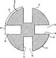
도 5는 내부 부품을 생략한 상태로 도 2의 선 5-5를 따라 취한 단면도;5 is a sectional view taken along line 5-5 of FIG. 2 with the internal components omitted;
도 6은 본 발명의 펌프에서 사용할 수 있는 회전자의 다른 실시예의 사시도;6 is a perspective view of another embodiment of a rotor that can be used in the pump of the present invention;
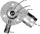
도 7은 도 1에 도시한 실시예의 회전자의 후면 사시도;7 is a rear perspective view of the rotor of the embodiment shown in FIG. 1;
도 8은 도 7에 도시한 회전자의 평면 사시도;8 is a top perspective view of the rotor shown in FIG. 7;
도 8a는 도 7에 도시한 회전자의 부분 절결 확대 사시도;FIG. 8A is a partially cutaway enlarged perspective view of the rotor shown in FIG. 7; FIG.
도 8b는 도 7에 도시한 실시예의 분해 사시도;8B is an exploded perspective view of the embodiment shown in FIG. 7;
도 9는 도 1에 도시한 펌프의 다른 실시예의 종단면도;9 is a longitudinal sectional view of another embodiment of the pump shown in FIG. 1;
도 10은 본 발명의 다중 회전자 혈액 펌프를 보이는 부분 절취 평면 종단면도;10 is a partial cutaway planar longitudinal cross-sectional view showing a multi-rotor blood pump of the present invention.
도 10a는 도 10에 도시한 혈액 펌프의 다른 실시예의 평면도;10A is a plan view of another embodiment of the blood pump shown in FIG. 10;
도 11은 본 발명의 축류 혈액 펌프의 다른 실시예의 분해 사시도;11 is an exploded perspective view of another embodiment of the axial flow pump of the present invention;
도 11a는 도 11에 도시한 실시예의 모터 회전자의 사시도;11A is a perspective view of the motor rotor of the embodiment shown in FIG. 11;
도 12는 본 발명의 실시예에 따르는 와류체를 갖는 혈액 펌프의 개략적인 단면도;12 is a schematic cross-sectional view of a blood pump having a vortex in accordance with an embodiment of the present invention;
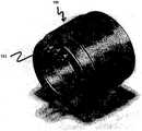
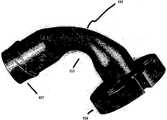
도 13은 도 12에 도시한 와류체를 갖는 혈액 펌프의 사시도;FIG. 13 is a perspective view of a blood pump having a vortex shown in FIG. 12; FIG.
도 14는 도 12에 도시한 와류체를 갖는 혈액 펌프의 분해 사시도;14 is an exploded perspective view of a blood pump having a vortex shown in FIG. 12;
도 15는 본 발명의 일 실시예에 따르는 와류체의 내부를 보이는 사시도;15 is a perspective view showing the inside of a vortex according to an embodiment of the present invention;
도 16은 도 15에 도시한 와류체의 내부를 보이는 평면도;FIG. 16 is a plan view showing the interior of the vortex shown in FIG. 15; FIG.
도 17은 본 발명의 다른 실시예에 따르는 와류체의 내부를 보이는 사시도;17 is a perspective view showing the inside of a vortex according to another embodiment of the present invention;
도 18은 본 발명의 또 다른 실시예에 따르는 와류체의 내부를 보이는 사시도;18 is a perspective view showing the inside of a vortex according to another embodiment of the present invention;
도 19는 본 발명의 또 다른 실시예에 따르는 와류체의 내부를 보이는 사시도;19 is a perspective view showing the inside of a vortex according to another embodiment of the present invention;
도 20은 본 발명의 또 다른 실시예에 따르는 하류 유동 정류기의 사시도;20 is a perspective view of a downstream flow rectifier in accordance with another embodiment of the present invention;
도 20a는 도 20에 도시한 유동 정류기의 저면도;20A is a bottom view of the flow rectifier shown in FIG. 20;
도 21은 본 발명의 또 다른 실시예에 따르는 하류 유동 정류기의 사시도;21 is a perspective view of a downstream flow rectifier in accordance with another embodiment of the present invention;
도 22는 본 발명의 또 다른 실시예에 따르는 하류 유동 정류기의 사시도;22 is a perspective view of a downstream flow rectifier in accordance with another embodiment of the present invention;
도 22a는 도 22에 도시한 유동 정류기의 저면도;FIG. 22A is a bottom view of the flow rectifier shown in FIG. 22; FIG.
도 22b는 도 22에 도시한 유동 정류기의 정면도;FIG. 22B is a front view of the flow rectifier shown in FIG. 22;
도 23은 본 발명의 또 다른 실시예에 따르는 하류 유동 정류기의 사시도;23 is a perspective view of a downstream flow rectifier in accordance with another embodiment of the present invention;
도 23a는 도 21a에 도시한 유동 정류기의 저면도;FIG. 23A is a bottom view of the flow rectifier shown in FIG. 21A;
도 24는 본 명세서에 도시 및 기술한 형태의 축류 회전펌프를 이용하는 인공심장의 사시도.24 is a perspective view of an artificial heart using an axial flow pump of the type shown and described herein.
도면에 도시된 본 발명의 개시에 관한 바람직한 실시예의 설명에 있어서, 특정 용어는 명료화를 위해서 채용하였다. 그러나, 본 발명의 개시는 그렇게 선택한 특정 용어로 한정되도록 의도한 것은 아니며, 각 특정 요소는 유사한 방식으로 작동하는 모든 기술적인 등가물을 포함하는 것으로 이해해야 한다.In describing the preferred embodiment of the present disclosure shown in the drawings, specific terminology has been employed for the sake of clarity. However, the disclosure of the present invention is not intended to be limited to the specific terminology so selected, and it is to be understood that each specific element includes all technical equivalents that operate in a similar manner.
이제, 도면, 특히 도 1 내지 도 5를 참조하면, 중공인 대략 관상의 펌프 하우징(12)을 포함하며, 환자의 혈관계를 통해 혈액을 펌핑하는데 도움을 주도록 적용된 혈액 펌프(10)의 실시예가 개시된다. 펌프 하우징(12)은 비자성이며, 타타늄 이나 항혈전성 강체이고 최소 와전류 손실을 보이는 적절한 세라믹 재료와 같은 적절한 생체적합성 재료로 만들어진다. 혈액이 화살표(18)로 도시한 방향으로 하우징을 통해서 유동하도록 하우징(12)은 혈액 입구 단부(11)와 혈액 출구 단부(11A)를 제공한다. 일 실시예에 있어서, 하우징(12)은 일정한 외경을 갖는 한편, 그의 내경의 입구부는 (13)으로 나타낸 바와 같이 일차로 합류된 다음에, 도 1에 참조번호 (52)로 나타낸 환상의 돌출부나 링을 제공하도록 (13A)와 같이 분기된다.Referring now to the drawings, and in particular to FIGS. 1-5, an embodiment of a
실질적으로 원통형인 회전자(14)는 펌프 하우징(12)의 내강 안에 위치되며, 하우징 내에서 유체를 펌핑하기 위한 임펠러로서 역할을 한다. 일 실시예에 있어서, 회전자(14)는 하우징의 내경의 분기부(13A)를 따르는 형상으로 테이퍼진 전단부(14A)를 구비한다. 합류 및 분기 직경부(13), (13A)는 가령, 외부 충격이 회전자에 충격이 가해져 그의 작업 축위치를 벗어나는 경향이 있는 경우, 회전자(14)가 관상의 하우징 내에서 적절한 축위치에 유지되도록 기구적인 스토퍼로서의 역할을 할 수 있다. 일부 실시예에 있어서, 회전자의 테이퍼진 전단부(14A)는 축방향 충격 하중에 대한 추가적인 보호를 위해서 하우징(12)의 분기 직경부(13A)의 표면과 협동하도록 이하에서 설명하는 형태의 유체 트러스트 베어링면을 구비할 수 있다. 하우징 분기 직경부(13A)와 회전자의 테이퍼진 전단부(14A) 간의 정렬 역시, 회전자의 후단부에 관해 이하에서 설명하는 바와 마찬가지로, 회전자의 전단부에 자기 축방향 예비하중을 제공하여 하우징 내에서 회전자를 부상시키고 무마모 상태로 유지하도록 돕는데 이용할 수 있다.The substantially
회전자(14)는 각각 회전자의 전단부(14A)의 진입부 또는 유입채널(22A)로부 터 후단부(14B)의 방출부 또는 배출채널(22B)까지 연장되는 하나 이상의 홈(22)을 포함한다. 이 홈(22)은 회전자에 걸쳐서 유체 유동채널을 제공한다. 일 실시예에 있어서, 회전자(14)에 형성된 다수의 홈(22)은 서로 떨어져 있으며 그들 사이에 다수의 외주 랜드 영역(35)을 제공한다. 각 홈은 회전자의 회전축에 대해 서로 평행일 필요는 없으나, 실질적으로 축방향으로 연장되는 1쌍의 측벽(16)에 의해서 제공된다.The
도 1 내지 도 4 및 도 6에 도시한 바와 같이, 각각의 홈(22)은 회전자의 회전축 둘레에서 적어도 부분적으로 만곡되고 실질적으로 축방향으로 연장되어 배출채널(22B) 내로 개구되는 중앙 유동채널(30)을 갖는다. 중앙 만곡부(30)는 유입채널(22A)이나 배출채널(22B)보다 좁다. 비교적 넓은 배출채널 및 그의 축방향 배향은 회전자로부터 혈액이 보다 용이하게 방출되도록 함으로써, 펌핑되는 혈액의 방출 유동특성을 향상시킨다. 홈(22) 및 그들의 측벽(16)은 회전자(14)가 (도 1의 실시예에서 시계방향으로) 회전함에 따라서, 화살표(18)로 나타낸 축방향으로 혈액을 압송하는 경향이 있다.As shown in FIGS. 1-4 and 6, each
일 실시예에 있어서, 홈(22)의 수는 2 내지 8개의 범위일 수 있으며, 전형적으로는 4개이다. 홈의 수에 관계없이, 회전자(14)의 외주면(23)(도 5)에서 그들의 전체 폭은 홈들 사이에 제공된 모든 랜드 영역(35)의 동일한 외주면(23)에서 합산한 총 원주 폭과 동일하거나 실질적으로 그보다 작다. 예시를 위해서, 도 5의 실시예에 도시한 바와 같이, 도 2의 선 5-5를 따라 취한 회전자의 단면에서 홈(22)의 외주면 폭은 화살표(26)로 도시되어 있다. 화살표(26)는 원호(28)의 길이로 측정한 바와 같이, 인접한 랜드 영역(35)의 폭보다 짧다. 합계로, 홈(22)을 따르는 중앙부에서, 홈(22)의 전체 폭은 각 랜드 영역(35)의 합산한 총 폭과 같거나 그보다 작다.In one embodiment, the number of
본 실시예에 있어서, 각각의 홈(22)의 깊이는 비교가능한 통상의 얇은 블레이드 축펌프 설계에서 블레이드의 반경 방향 범위보다 크다. 예를 들면, 심장 펌프용도를 위해, 그의 외주면으로부터 홈(22)의 평균 깊이는 1㎜ 내지 5㎜의 범위 내에 들 수 있다. 일부 실시예에 있어서, 홈의 평균 깊이는 회전자 직경의 약 1/3이지만, 회전자의 반경보다는 작다. 다른 실시예에 있어서, 홈은 회전자 전단부의 유입채널(22A)에서 더 깊고, 회전자 후단부의 배출채널(22B)에서 더 얕다.In this embodiment, the depth of each
도 2를 참조하면, 혈액 펌프(10)는 회전자를 추가로 포함한다. 이 펌프는 회전자(14)의 각 넓은 랜드 영역(35) 내에 형성된 다수의 비교적 큰 영구 구동자석(34)(점선으로 표시함)을 구비한다. 본 발명의 일 실시에에 따라서, 회전자의 영구 구동자석(34)은 랜드 영역(35)의 외주부의 선택한 부분을 자화시켜 만들 수 있다. 이것은 가령, 등방성일 수 있는 자기 합금으로 회전자를 구성하고, 원하는 외주부를 자화시켜 다양한 기하학적 배향을 갖는 다수의 자극을 형성함으로써, 달성할 수 있다. 생체 적합성이므로 아무런 추가적인 코팅을 필요로 하지 않는 자기 합금을 사용하는 것이 바람직하다. 그러한 회전자는 다수의 부품으로 형성된 임펠러보다 제조가 용이하고 저렴하다.Referring to FIG. 2, the
도 1을 참조하면, 모터는 전도성 코일(38)을 갖는 모터 고정자(36)도 포함한다. 코일은 관상의 하우징(12)과 회전자(14)를 둘러싸는 밀폐체(40) 내에 배치된 다. 모터 고정자(36)는 코일(38)에 전력을 통상적으로 공급하여 회전자(14)를 회전시켜 자속을 생성하는 기능을 한다. 회전자의 넓은 랜드 영역(35)에 결합된 영구 구동자석은, 모터 고정자에 의해 생성된 자속과 우수한 전자기 결합을 제공하도록 자기 특성, 길이 및 단면적을 선택한다. 랜드 영역의 비교적 큰 표면적으로 인해서, 회전자 자석의 특징 및 배치는 비교적 쉽게 달성된다. 이 배열은 강한 전자기 결합 및 회전자를 제위치에 유지하는데 필요한 축방향 자기 강도를 제공한다. 일 실시예에 있어서, 고정자 자속과 회전자의 구동 자석 간의 자기 결합으로 토크를 생성하여 회전자(14)가 시계방향으로 회전되도록 한다. 당업자라면 알 수 있는 바와 같이, 회전자는 본 발명의 범위를 벗어남이 없이 반시계 방향으로는 회전할 수 없다.Referring to FIG. 1, the motor also includes a
모터는 3상의 무브러시(brushless) DC 모터일 수 있다. 일 실시예에 있어서, 모터는 도넛형 3상 및 Y자 연결 설계로 할 수 있다. 고정자는 전형적인 반경 방향 자속 갭 모터와 일치하는 백 아이언(back iron) 설계를 가질 수 있다. 필요하다면, 모터 고정자는 관상의 하우징(12) 상에서 제위치로 미끄럼 이동하는 별도의 반구 밀봉형 밀폐체(40)를 포함할 수 있다. 모터 고정자 하우징을 제위치에 고정하기 위해서 밀폐체(40) 외부면에 브레이징 용접링을 사용할 수 있다. 레이저 용접은 모터 고정자 밀폐체(40)를 하우징에 고정하여 밀봉 시일(seal)을 얻기 위한 하나의 가능한 기술이다. 이것을 달성하기 위한 특수 기술은 본 기술분야에 공지되어 있다.The motor may be a three phase brushless DC motor. In one embodiment, the motor can be a toroidal three-phase and Y-shaped connection design. The stator may have a back iron design that matches a typical radial flux gap motor. If desired, the motor stator may include a separate hemispherical
도 6을 참조하면, 본 발명의 혈액 펌프에 대한 회전자(14b)의 다른 실시예가 개시되어 있다. 회전자(14b)는 중앙부(30)를 갖는 유동채널(22) 사이에 6개의 외주 랜드 영역(35b)을 구비하는 것으로 도시되어 있다. 그 밖에, 회전자(14b)의 특징 및 구성은 여기에 개시된 다른 실시예의 회전자와 유사하다.Referring to Figure 6, another embodiment of a
도 7, 도 8 및 도 8a를 참조하면, 도 1 내지 도 5에 도시한 회전자와 유사한 회전자(14)가 도시되어 있다. 회전자(14)의 외주 랜드 영역(35)은 각각 하나 이상의 유체 트러스트 베어링면(44), (46)을 구비한다. 각각의 트러스트 베어링면(44), (46)은 소정의 외경을 갖는 관련 랜드 영역의 표면을 따라서 배치된다. 회전자(14)의 (시계방향)회전의 관점에서 각 베어링면의 전단부(47)는 도 8 및 도 8a에 참조번호 (45)로 나타낸 바와 같이, 관련 랜드 영역의 표면 이하에서 소정량만큼 오목하게 들어갔다. 다음에 오목면은 원호를 따라 랜드 영역에 걸쳐서 만곡되는 방식으로 점차 테이퍼지며, 이때 만곡 축은 회전자의 회전축과 동축일 필요는 없다. 테이퍼진 베어링면은 후방 단부(48)에서 종결되는 데, 이 지점에서 각 베어링면(44), (46)은 원만한 천이(transition)를 갖는 랜드 영역의 외주부로 날개처럼 만들어지며, 랜드 영역의 연속되는 하류면에 대해서는 더 이상 오목하지 않다.7, 8 and 8a, a
회전자가 회전함에 따라서, 각 랜드 영역(35) 상의 각 트러스트 베어링(44), (46)은 베어링면 상으로 혈액을 모으게 되며, 그로 인해 혈액은 베어링면과 관상의 펌프 하우징의 내벽 사이로 흐른다. 트러스트 베어링면의 테이퍼진 형상의 효과로는 베어링면과 관상의 펌프 하우징의 내벽 사이에 생성된 감소 또는 수축되는 영역을 통해서 혈액이 강제로 흐르도록 하는 것이 있다. 이것은 수축 영역 내에서 상류 유압이 증가되는 결과를 가져오며, 이 베어링면 영역에 대해 압력을 가해서 회전하는 회전자의 반경 방향 지지부를 위한 정미 대칭 힘을 만든다. 회전자 상에 반경 방향 압력이 야기되도록 하는 이러한 방식의 유체 트러스트 베어링은 미국특허 제5,840,070호에 개시된 바와 같이, 대체로 종래기술에 잘 공지되어 있다. 그러므로 회전자 랜드 영역의 표면에 생성되는 유체의 힘은 부상한 회전자를 유지하고, 도 1에 도시한 방식으로 관상의 하우징(12)의 내강 속에서 중심이 유지되며, 물리적으로 접촉하는 베어링면을 구비하지 않아도 동적인 반경 방향 충격 하중의 힘에 견디게끔 한다. 트러스트 베어링면(44), (46)은 랜드 영역(35)의 외주면에 직접 형성하거나, 랜드 영역의 외주면에 형성된 적절한 공동 내에 배치하거나 적절한 커버에 의해 제위치에 유지할 수 있다.As the rotor rotates, each thrust bearing 44, 46 on each
일부 실시예에 있어서, 유체 트러스트 베어링면은 회전자의 전단 또는 후단부부에 생성된다. 가령, 도 1 내지 도 3을 참조하면, 회전자의 전단부(14A)에서 표면적(20)은 관상의 펌프 하우징의 분기 내부면(13A)과 협동하도록 적절한 트러스트 베어링 형상으로 테이퍼져 있다. 그러한 트러스트 베어링은 도 1에 도시한 바와 같이, 회전자의 좌측으로의 종방향 운동을 견딜 수 있다. 또한, 환형상 링(52)을 부분적으로 제공하는 분기부(13A)는 필요시, 회전자가 시계방향으로 회전하면서 작동함에 따라서 회전자(14)와 링(52) 간의 접촉을 방지하도록 인접한 회전자면과 협동하는 유체 트러스트 베어링을 포함한다.In some embodiments, the fluid thrust bearing surface is created at the front or rear end of the rotor. For example, with reference to FIGS. 1-3, the
유체 트러스트 베어링면은 그의 전단부(14B) 근처의 회전자 상에도 배치될 수 있는데, 하우징의 출구 단부(11A) 근처에서 관상의 펌프 하우징의 내경은 도 1에 점선으로 도시한 바와 같이 수축되어 유입 단부(11) 근처의 링(52)과 유사한 환형상 링(53)을 제공한다. 링(53)의 측면 상에 형성되거나 회전자 상에 있는 그러한 트러스트 베어링은 이하에서 설명하는 자석(56), (57)의 반발 자극을 대체 또는 보충하는 유사한 목적을 수행한다. 그러한 트러스트 베어링은 회전자용 반경 방향 및 축방향 지지부의 하나 또는 모두를 제공하고, 충격 하중에 대한 저항력을 증가시켜 회전자의 안정성을 향상시키는 역할을 한다.The fluid thrust bearing face may also be disposed on the rotor near its
회전자의 외주면 상의 유체 트러스트 베어링은 우수한 표면 세정을 제공한다. 트러스트 베어링에 의해 생성된 원심력은 유체를 하우징의 내주면쪽으로 밀어 증가된 혈액 유동을 제공하는 경향이 있으며, 이는 혈전증에 대한 펌프의 저항을 향상시킬 수 있다. 반대로, 회전축에 근접한 종래의 유체 베어링은 감소된 표면 세정을 가지므로, 혈액 응고에 대한 큰 잠재성을 가져온다. 그러므로, 본 발명에 의해서, 혈액 응고를 감소시키는 상태가 제공되기 때문에, 혈액 펌프와 환자에 대해 보다 적은 양의 항응고제를 사용할 수 있으며, 이는 환자에게 보다 적은 부작용을 가져올 수 있다. 필요하다면, 유체 트러스트 베어링면은 회전자의 표면상에 나선 형태로 정렬하여, 회전자의 회전에 따라 이동하는 혈액에 의한 표면 세정을 향상시킬 수 있다.Fluid thrust bearings on the outer circumferential surface of the rotor provide excellent surface cleaning. The centrifugal force generated by the thrust bearing tends to push the fluid towards the inner circumferential surface of the housing to provide increased blood flow, which can improve the pump's resistance to thrombosis. Conversely, conventional fluid bearings close to the axis of rotation have a reduced surface cleaning, which brings great potential for blood coagulation. Therefore, because the present invention provides a condition for reducing blood coagulation, smaller amounts of anticoagulant can be used for blood pumps and patients, which can result in fewer side effects for patients. If desired, the fluid thrust bearing surface can be aligned in a spiral form on the surface of the rotor to improve surface cleaning by blood moving as the rotor rotates.
회전자 상에서 축방향으로 작용하는 유체 트러스트 베어링에 대한 다른 예로서, 회전자의 전단, 후단 또는 양단 내의 각 랜드 영역(35)에 회전자 영구 유지자석을 배치할 수 있다. 대응하는 하나 이상의 영구자석을 각 회전자 유지자석과 인접한 관상의 펌프 하우징의 내부나 그 위에 배치하여, 반발 자력을 생성시킴으로써 하우징 내에서 회전자의 축방향 정렬을 유지할 수 있다. 단지 예시를 위해서, 도 1 및 도 2에는 회전자(14)의 전방단의 랜드면 영역 상에 영구자석(56)을 점선으로 도 시하였다. 대응하는 고정자 영구자석(57)이 관상의 하우징(12)을 둘러싸는 밀폐체(40) 내에 배치된다. 회전자 자석(56)은 적절한 회전자 재료의 자화에 의해서 형성할 수 있다. 도 1에 도시한 바와 같이, 회전자 자석(56)과 고정자 자석(57)의 북극이 서로 인접하거나 대면하면, 반발 자력은 회전자가 적절한 축위치에 유지되도록 돕게 된다. 따라서, 우측으로의 회전자의 종방향 또는 축방향 운동은 자석(56), (57)의 반발작용에 의해서 제한된다. 물론, 대략 유사한 효과를 얻기 위해서, 자석의 남극을 마찬가지의 방법으로 서로 대면하도록 놓을 수 있다. 자석(57)은 링 자석 또는 전자기 코일을 포함할 수 있음을 이해할 것이다.As another example of a fluid thrust bearing acting axially on the rotor, the rotor permanent retaining magnet may be disposed in each
도 8a를 참조하면, 일 실시예에 있어서, 각각의 트러스트 베어링면은 트러스트 베어링면의 각 측면을 따라서 제공된 덮개(49)를 구비한다. 각 베어링면의 오목부에 의해 생성된 작은 높이의 측벽에 의해 제공된 이들 덮개는 베어링면으로부터의 유체의 누출량을 감소시키고, 보다 높은 수준의 반경 방향 압력의 개발을 허용한다. 그러한 덮개에 의해서 허용가능한 수준까지 누출이 감소되면, 베어링에 대한 부하용량을 거의 2배로 할 수 있다.Referring to FIG. 8A, in one embodiment, each thrust bearing surface has a
용혈을 줄이기 위해서 각 회전자 트러스트 베어링면 하류에는 선택적으로 압력 완화면을 구비할 수 있다. 이 압력 완화면은 트러스트 베어링면의 후방 단부(48)와 인접해 있고 하우징벽으로부터 약간 분기되는 외주 랜드 영역의 일부로 구성된다. 트러스트 베어링면 위를 지나는 혈액은, 따라서 압력 완화면을 가로질러 회전자에 형성된 홈(22) 중 하나와 인접한 곳으로 보내진다. 도 7 및 도 8에서 볼 수 있는 회전자의 후방 단부의 둥근 면(54)은 혈액이 회전자의 유동채널 내로 용이 하게 진입하도록 한다. 그러므로, 공지된 형태의 축류 혈액 펌프에 비해 많은 이점을 갖는, 넓은 외주 랜드 영역을 갖고 반경 방향 또는 축방향 지지용 덮개식 유체 트러스트 베어링을 이용하는 축류 펌프가 제공된다.In order to reduce hemolysis, a pressure relief surface may optionally be provided downstream of each rotor thrust bearing surface. This pressure relief surface consists of a portion of the outer land region adjacent the
일부 실시예에 있어서, 회전자(14)는 압축 결합 네오디뮴 또는 알니코(알루미늄 니켈 합금), 또는 약 70 내지 80 중량%의 백금 및 약 20 내지 30 중량%의 코발트 합금과 같은 강자성 재료의 단일 조각을 기계가공, 몰딩, 또는 주조에 의해서 만들 수 있다. 일부 실시예에 있어서, 합금 내에는 기본적으로 76 내지 79 중량%의 백금이 존재한다. 일부 실시예에 있어서, 합금은 기본적으로 21 내지 24 중량%의 코발트를 함유할 수 있다. 일 실시예에 있어서, 일체형 원피스 회전자는 기본적으로 77.6 중량%의 백금과 22.4 중량%의 코발트로 구성된다. 그러한 회전자는 우수한 자기 특성을 얻기 위해서 통상적으로 열처리되며, 원하는 대로 북극 및 남극의 자극으로 자화시킬 수 있다.In some embodiments, the
그러한 회전자의 이점은 통상적인 금속 작업 및 주조방법을 이용하여 백금 및 코발트 합금으로 제조된 일체형 원피스를 복잡한 형상으로 쉽게 제조할 수 있는 점이다. 또한, 그러한 합금은 자기적으로 등방성이므로, 어떤 기하학적 배향을 갖는 다수의 자극으로 부품들은 쉽게 자화될 수 있다. 이들 특성에 의해 회전자를 고체 합금 조각으로 제조하는 것이 가능하며, 따라서 종래의 심실 보조장치의 경우와 같이, 자석 및 지지 구조의 조립체를 구축할 필요가 없어져, 제조 비용의 감소를 가져온다. 또한, 본 발명에서 사용한 합금은 생체 적합성이며, 부식에 대한 높은 저항성을 가짐과 아울러, 31Rc 정도의 록크웰 경도를 갖는데, 이것으로 외부 하드 코팅을 실시할 필요가 없게 된다. 원하는 대로 회전자 재료는 등방성 또는 이방성일 수 있음을 이해할 것이다.The advantage of such a rotor is that one-piece ones made of platinum and cobalt alloys can be easily manufactured into complex shapes using conventional metal working and casting methods. In addition, since such alloys are magnetically isotropic, parts can be easily magnetized with multiple magnetic poles of any geometric orientation. These properties make it possible to manufacture the rotor from solid alloy pieces, thus eliminating the need to build an assembly of magnets and support structures, as in the case of conventional ventricular assist devices, resulting in a reduction in manufacturing costs. In addition, the alloy used in the present invention is biocompatible, has a high resistance to corrosion, and has a Rockwell hardness of about 31 Rc, thereby eliminating the need for external hard coating. It will be appreciated that the rotor material may be isotropic or anisotropic as desired.
제조 후에, 회전자 둘레에 밀봉 시일을 형성함으로써 산화를 막기 위해서, 파릴렌, 또는 실리콘 같은 유기 고분자의 절연 보호 고분자 코팅으로 회전자를 처리할 수 있다. 이것의 상부에 있어서, 마모와 마멸을 막기 위해서, 절연 고분자 코팅 위에 단단한 윤활 보호 코팅을 도포할 수 있다. 그러한 코팅은 질화 크롬, 질화 티타늄, 또는 그 밖에 상업적으로 이용할 수 있는 ME92, Med Co 2000, 또는 DLC(Diamond like Carbon) 같은 코팅을 포함할 수 있다. 대안적으로는, 상술한 바와 같이, 백금 코발트 합금 같은 생체적합성 자기 등방성 합금의 사용으로 보호 코팅의 사용은 필요 없게 된다. 영구 심장 심실 보조장치에 대한 설계에 있어서, 그러한 회전자는 10㎜의 외경 및 20㎜의 길이를 가져, 생리학적으로 상이한 혈압에 대해 분당 2 내지 10리터의 유량을 제공하는 원통형 디바이스일 수 있다.After manufacture, the rotor can be treated with an insulating protective polymer coating of organic polymers, such as parylene or silicon, to prevent oxidation by forming a sealing seal around the rotor. On top of this, a hard lubricating protective coating can be applied over the insulating polymer coating to prevent wear and abrasion. Such coatings may include coatings such as chromium nitride, titanium nitride, or other commercially available ME92, Med Co 2000, or Diamond like Carbon (DLC). Alternatively, as described above, the use of biocompatible magnetic isotropic alloys such as platinum cobalt alloys eliminates the need for protective coatings. In the design for permanent cardiac ventricular assist, such a rotor may be a cylindrical device having an outer diameter of 10 mm and a length of 20 mm to provide a flow rate of 2-10 liters per minute for physiologically different blood pressures.
도 8b를 참조하면, 회전자(14)의 실시예는 각각의 랜드 영역(35)에 형성된 오목홈(35A)을 구비하며, 홈은 각각 공동(55)을 포함한다. 각 공동(55)은 개별 영구 구동자석(73)을 수용하도록 적용된다. 영구 구동자석(73)은 도 2와 관련하여 상술한 자화영역(34)과 동일한 목적을 수행한다. 본 실시예에 있어서, 랜드 영역 오목홈(35A)은 각각의 공동(55)에 인접한 공동(74)을 구비한다. 공동(74)은 도 1 및 도 2와 관련하여 상술한 회전자 유지자석(56)의 기능을 수행하는 개별 영구 유지자석(75)을 수용하도록 적용된다. 또한, 랜드 영역 오목홈(35A)은 중량 감소의 목적 및 필요시 회전자 내에서 동적 회전 균형을 달성하기 위해 형성한 구멍(76)을 구비 한다. 외곽 커버(77)는 각각의 랜드 영역 오목홈(35A) 내로 삽입되어 개별 구동자석(73)을 유지하고 자석(75)을 회전자 상의 제위치에 유지하기 위해 적용한다. 본 실시예에 있어서, 커버(77)는 도 7, 도 8 및 도 8a와 관련하여 위에서 설명한 회전자용 유체 트러스트 베어링면(44), (46)을 포함한다.Referring to FIG. 8B, the embodiment of the
도 9을 참조하면, 하우징(12)의 출구 내에 삽입된 슬리브(70)를 가지며 감소된 내경 영역(71)을 갖는, 도 1의 펌프의 실시예가 도시되어 있다. 내경이 감소된 영역(71)은 하나의 축방향, 도 9에서는 우측으로의 이동에 대해 회전자(14)를 기구적으로 유지하는 스토퍼로서의 역할을 하므로, 자석(56), (57)이 필요 없게 된다. 또한, 슬리브(70)의 감소된 내경 형상은, 이것이 밀봉되지 않은 형상과 비교하여 감소된 유량을 가져옴에 따라, 상기 배열은 본 발명의 축류 펌프를 소아용으로 사용하기에 적합하도록 한다.Referring to FIG. 9, an embodiment of the pump of FIG. 1 is shown, having a
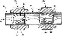
도 10을 참조하면, 일련의 축류 혈액 펌프(60)는 다수의 회전자(14c)가 축방향으로 공간 이격된 관계로 공통축(64) 상에 장착되는 공통 원통형 하우징(62)을 갖는다. 그러한 일 실시예에 있어서, 회전자는 축(64)에 의해서 공통으로 구동되어 일체로 회전한다. 그러한 장치는 동시계속 출원 일련번호 제11/118,551호에 개시되어 있으며, 그 내용은 참고로서 여기에 인용한다. 각각의 회전자(14c)는 이전 실시예의 랜드 영역(35)과 유사한 외주 랜드 영역(35c)을 갖는다. 이 수단에 의해서, 직렬연결의 회전자를 갖는 다단 펌프의 형태로 증가된 펌핑력을 제공할 수 있다. 따라서, 보다 작은 직경의 고용량 펌프를 제공할 수 있다.Referring to FIG. 10, a series of axial flow pumps 60 has a common
각 회전자에 하나씩 전도성 코일을 포함하는 모터 고정자(36c)가 제공됨으로 써, 각각의 회전자는 공통축을 갖는 그들의 연결을 제외하고, 이전 실시예에 관해 기술한 회전자와 유사한 방식으로 기능을 한다. 회전자(14c)와 고정자(36c)는 이전 실시예의 어느 것과 동일한 설계일 수 있으나, 각 회전자는 홈들 사이에 동일한 수의 홈이나 랜드 영역을 가질 필요는 없다.By providing a
일련의 3개의 회전자 중에서 적어도 2개의 하류에 펌프 하우징(62)의 내벽으로부터 반경 방향 내측으로 연장되도록 전통적인 얇은 블레이드 설계의 고정자 블레이드(66)를 장착할 수 있으나, 본 발명의 축류 펌프에서는 보통 그러한 블레이드를 필요로 하지 않는다. 고정자 블레이드(66)는 유동이 다음 회전자와 충돌하기 전에 회전자로부터 축류 출력의 회전 모멘트를 감소시키도록 기능한다. 이 배열은 혈액 또는 다른 유체에 보다 많은 유압 일이 추가되도록 허용한다. 필요시, 임의의 원하는 수의 상기 축방향 연장 블레이드(66)를 제공할 수 있다. 또한, 필요시, 각 고정자 블레이드(66)의 전단 및 후단은 회전자에 추가적인 축방향 지지부를 제공하는데 적절한 유체 트러스트 베어링면을 구비할 수 있다. 또한, 고정자 블레이드(66)는 회전자를 지지하는 자석 베어링을 제공하기 위한 일체형 영구자석도 구비할 수 있다. 각 회전자의 적절한 전단 또는 후단 내에, 또는 그 위에 장착된 영구자석은 반발 자극을 제공하여 회전자의 축방향 안정성에 도움을 줄 수 있다.It is possible to mount the
도 10에 도시한 실시예에 있어서, 각각의 모터 고정자(36c)는 대응하는 회전자와 축방향으로 정렬된다. 그러한 정렬은 자기 결합 또는 반발을 수용하여 여분의 축방향 자기 지지부를 제공하도록 변경할 수 있다.In the embodiment shown in FIG. 10, each
도 10a를 참조하면, 다른 다중 회전자 축방향 펌프는 상술한 회전자(14)의 특성을 갖는 하나의 펌프 회전자(14c)를 각각 구비하는 다수의 혈액 펌프(60)로 구성된다. 회전자(14c)는 공간 이격된 관계로 축방향으로 정렬되어 있으며, 단일 회전자 펌프와 관련하여 상술한 바와 같이, 최소 와전류 손실을 보이는 생체적합성 재료로 만들어진 공통의 원통형 하우징(62)을 통해서 혈액 또는 다른 유체를 연속으로 펌핑하도록 적용된다. 본 실시예에 있어서, 개별 회전자(14c)는 연결축 없이 독립적으로 기능한다. 모터 고정자(36c)는 각각 회전자당 하나씩 전술한 실시예에서와 같은 전도성 코일을 포함함으로써, 각 회전자는 전술한 실시예와 유사한 방식으로 기능한다. 또한, 고정자(36c)는 상술한 바와 같이 설계할 수 있다. 일제히 작용하는 다중 회전자(14c)는 추가된 펌핑력을 제공하며, 따라서 1단 펌프보다 적은 직경의 고용량 펌프가 가능하며, 환자의 혈관계 내에 직접 이식하거나 그렇지 않으면 환자의 외상을 감소시키도록 적용할 수 있다.Referring to FIG. 10A, another multi-rotator axial pump consists of a plurality of blood pumps 60 each having one
일 실시예에 있어서, 독립적으로 회전가능한 회전자(14c)는 동일속도로 회전한다. 다중 회전자의 회전속도는 원하는 대로 서로 달리할 수 있음을 이해할 수 있을 것이다. 일부 실시예에 있어서, 하나의 회전자는 시계방향으로 회전할 수 있으며, 그의 홈이 화살표 방향(63)으로 관상의 하우징(62)을 통해서 혈액 또는 다른 유체를 구동하는데 도움이 되도록 배향될 수 있다. 인접한 회전자는 그의 홈이 반시계 방향 회전시 동일한 방향(63)으로 혈액을 구동하는데 도움이 되도록 배향될 수 있다. 그러므로, 다중 회전자가 반대방향으로 회전하더라고, 그들은 함께 작동하여 화살표 방향(63)으로 유체를 구동한다. 이 배열의 이점은, 시계방향으로 회전하는 회전자의 하류에서 반시계 방향으로 회전하는 회전자가 상류 회전자에 의해 펌핑된 유압에 가해지는 회전 모멘트에 대해 반작용하는 경향이 있는 것이다. 이것은 유체에 보다 많은 유압 일이 추가되도록 허용한다. 개별 고정자(36c)에 가해진 동력에 따라서, 원하는 대로 개별 회전자를 서로 동일, 또는 상이한 회전 속도로 구동시킬 수 있다. 따라서, 오정렬된 모터 구동 파형으로 인한 악영향이 감소된다.In one embodiment, the independently
일부 실시예에 있어서, 다중 회전자 펌프는 하우징 내에서 회전자들 사이에 위치되는 고정형 와류 억제 블레이드를 구비하지 않는다. 그러한 블레이드에 대한 필요성은 각 회전자의 반대방향 회전 특성에 의해서 줄어든다.In some embodiments, the multi-rotor pump does not have a fixed vortex suppression blade positioned between the rotors in the housing. The need for such blades is reduced by the opposite rotational characteristics of each rotor.
일부 실시예에 있어서, 2개 이상의 회전자가 존재한다. 인접한 회전자가 서로 반대방향으로 회전함으로써, 시계방향으로 회전하는 회전자는 펌프 하우징 내에서 축방향으로 정렬되어 반시계 방향으로 회전하는 회전자와 산재된다.In some embodiments, two or more rotors are present. As adjacent rotors rotate in opposite directions, the clockwise rotating rotor is interspersed with the rotor axially aligned and rotating counterclockwise within the pump housing.
상술한 바와 같이, 다단 형상의 영구 심실 보조장치는 6㎜의 외경과 15㎜의 길이를 가져, 상술한 바와 같이, 생리학적으로 상이한 혈압에 대해 분당 2 내지 8리터의 유량을 제공할 수 있다. 그러한 다단 펌프는 신체의 외부에서 작동하는 외주 용기 혈액 주입펌프로서 사용하거나, 양(兩)심실 지원 및 토탈 인공심장 작용까지도 제공할 수 있다. 다중 회전자를 공통축에 그룹화할 필요는 없으며, 각 회전자에 대한 모터 고정자에 에너지가 가해져서 인접한 다른 회전자의 회전과 각기 독립해서 시계방향 또는 반시계 방향 회전을 달성할 수 있음을 이해할 것이다.As described above, the multi-stage permanent ventricular assist device has an outer diameter of 6 mm and a length of 15 mm, as described above, to provide a flow rate of 2 to 8 liters per minute for physiologically different blood pressures. Such multistage pumps may be used as outer vessel blood infusion pumps that operate external to the body, or may provide both ventricular support and total cardiac action. It will be appreciated that there is no need to group multiple rotors on a common axis, and that energy can be applied to the motor stator for each rotor to achieve clockwise or counterclockwise rotation independently of the rotation of other adjacent rotors. .
도 11은 본 발명의 실시예에 따르는 다른 혈액 펌프의 구성을 보이는 분해 사시도이다. 펌프는 조립된 밀폐체 내의 적소에서 관상의 하우징(104)과 주변 모터 고정자(110)를 함께 밀봉하도록 조립되는 제1 외부 캐뉼러(cannula)형 밀폐 체(102a) 및 제2 또는 배출영역(102b)을 포함한다. 내부 관상의 하우징(104)과 밀폐체(102a) 간의 혈액 누출을 막기 위해 O-링(124A)을 사용할 수 있다. 본 실시예에 있어서, 전체 관상의 하우징 및 주변 모터 고정자는 감소된 직경의 유입구(105)를 갖는 캐뉼러형 구조로 밀폐되어 있으며, 이는 총탄 같은 형상을 제공한다.11 is an exploded perspective view showing the configuration of another blood pump according to an embodiment of the present invention. The pump includes a first outer cannula-
모터 고정자(110)는 모터 코일의 3상 동작을 위해 3개의 전기 케이블(103)(도 11a에 도시한 모터 고정자의 확대도에서 가장 잘 보임)를 갖는다. 전기 케이블은 3개의 영역(120k), (120a), (120b)을 포함하는 적절한 케이블 도관 내에 넣을 수 있다. 본 발명의 정신으로부터 벗어남이 없이, 필요한 고속 통신 또는 증가된 효율의 적용을 위해서 다른 모터 설계를 선택할 수 있음을 이해할 것이다.The
도 12 내지 도 16은 축류 펌프에 의해 배출된 혈액의 축방향 유동의 회전 운동에너지가 참조 번호 (106)으로 나타낸 와류체에 의해 펌프의 출구에서 압력 유동으로 변환되는 혈액 펌프의 실시예를 나타낸다. 와류체를 본 발명의 축류 펌프와 결합할 필요는 없지만, 이것은 혈전 형성을 더욱 최소화하고 혈액이 혈관계로 들어감에 따라서 펌핑된 혈액의 압력을 증가시키는 혈액 유동 특성을 개선하기 위한 선택적인 실시예이다.12-16 show an embodiment of a blood pump in which the rotational kinetic energy of the axial flow of blood discharged by the axial flow pump is converted into pressure flow at the outlet of the pump by the vortex indicated by
도 12 및 도 13을 참조하면, 혈액 펌프(100)는 실질적으로 원통형인 외부 밀폐체 또는 캐뉼러(102a)를 포함한다. 캐뉼러(102a)는 약간 둥글거나 총탄 형상, 또는 혈액이 펌핑 챔버로 들어가는 입구(116)를 갖는 감소된 직경의 유입 단부(105)를 가질 수 있다. 펌핑 챔버는 캐뉼러의 내경보다 작은 외경을 갖는 실질적으로 관상인 내부 하우징(104)에 의해 제공된다. 상술한 바와 같이, 애뉼러(102a)와 관상 의 하우징(104)은 티타늄이나 세라믹 같은 생체적합성 비자성 재료로 만들 수 있다.12 and 13, the
하우징(104)의 외측 및 하우징(104)과 캐뉼러(102a) 간에 형성된 환형상 공간의 캐뉼러(102a) 내에 모터 고정자 링(110)을 배치할 수 있다. 위에서 상세히 설명한 바와 같이, 고정자 링(110)의 코일용 3상 제어 와이어는 와류체(106)의 일부로서 제공될 수 있는 포트(118)를 통해 펌프를 빠져나가는 제어 케이블관(120k)을 통해 전원에 연결된다. 위에서 상세히 설명한 형태의 회전자(108)는 작동시에 하우징(104) 내에서 자기적으로 또는 유압적으로 부상할 수 있으며, 고정자 링(110) 내에서 중심이 유지되어 입구(116)로 들어가는 혈액 또는 유체의 축방향 유동을 제공할 수 있다.The
회전자(108)에 의해 펌핑된 혈액이 와류체(106)의 중앙 챔버(114)(도 12) 내로 이동하도록 와류체(106)는 캐뉼러(102a) 및 관상의 하우징(104)에 대해 유체 기밀 연결로 밀봉된다. 도 12 및 도 14를 참조하면, 내부 관상의 하우징(104)에 대한 와류체의 유체 기밀 연결을 확실히 하기 위해서 O-링(124B)을 사용할 수 있다. 밀봉 연결을 확실히 하기 위해서 하나 이상의 나사(126)를 사용할 수 있다.The
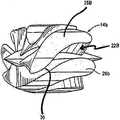
도 15 및 도 16에 도시한 바와 같이, 와류챔버(114)는 펌프 회전자(108)의 회전축을 따르는 와류체의 베이스로부터 펌프축을 따라서 내부로 돌출되는 하류 중앙 기둥(112)에 의해 제공된 바와 같이 단면이 둥글 수 있다. 중앙 기둥(112)은 회전자(108)의 하류단 쪽으로 연장되지만, 그 단과 접촉하지는 않으며, (도 12, 도 14 및 도 15에 도시한 바와 같이) 상부가 돔형인 실린더일 수 있거나, 이하에서 상 세히 설명하는 바와 같이, 펌프 회전자로부터 배출된 혈액의 유동에 영향을 주도록 기능하는 다른 형상일 수 있다.As shown in FIGS. 15 and 16, the
회전자(108)에 의해 구동되어 축류 펌프의 펌핑 챔버로부터 와류챔버로 들어가는 혈액은 회전자의 회전축 둘레에서 회전 또는 나선회전 모멘트를 갖는다. 유동의 회전 모멘트는 회전자의 바로 아래의 혈액 유동 중앙부에 저압 영역을 생성한다. 저압 영역의 어느 정도까지는 회전자의 전단부(14B)에서 테이퍼진 축 연장부(24)(도 1)에 의해서 완화된다. 또한, 중앙 기둥(112)은 혈액이 와류체의 챔버(114) 내로 들어감에 따라서 이 저압 영역을 하류 회전 혈액 유동 특성으로 채우는 경향이 있다. 다음에 혈액은 와류체의 환형상 챔버(114)를 채우며, 시스템의 유압은 도 13 내지 도 16에 도시한 와류체 배출 또는 출구(122)까지 챔버(114)를 통해서 실질적으로 원심 방향으로 혈액 흐름의 유동이 일어나도록 함으로써, 배출압력을 안정화시킨다. 본 실시예에 있어서, 와류체는 블레이드가 없으며, 방출 혈액 유동은 혈관계 내의 혈액 유동의 길이방향 특성과 일치한다. 특히, 본 실시예의 혈액 펌프는 와류부가 심장의 외측에 유지되는 한편, 캐뉼러부는 심실의 정점을 가로지르도록 이식된다. 와류체의 배출 또는 출구를 환자의 혈관계의 동맥에 연결하기 위해 이식조직(도시 생략)을 사용한다.Blood driven by the
이제, 도 17을 참조하면, 관련 축류 펌프의 펌프실 내로 대략 축방향으로 연장되는 유동 정류기에 관한 다른 구성을 갖는 원심 와류체(123)의 실시예가 도시되어 있다. 본 실시예에 있어서, 와류체(123)는 와류챔버의 밖으로, 그리고 상술한 바와 같이 축방향 펌핑 챔버(도시 생략)의 축에 대해서 및 그 축을 따라서 내부로 돌출되는 이중 다리형 고정자 요소(125)가 연장되는 대략 원형 단면의 유동챔버(133)를 갖는다. 고정자 요소는 펌프의 회전축과 실질적으로 동축상에서 연장되는 1쌍의 평행 다리(126), (128)를 갖는다. 각 지지다리(126), (128)의 내측단부가 만곡되어 있으며, 고정자 요소(125)의 종축 및 관련 펌핑 챔버의 축에 대해 약 45°의 각도로 돌출되도록 다리(128)의 단부(端部)(130)는 만곡되어 있다. 지지다리(126)의 내측단부(132) 역시 펌프축에 대해 45°의 각도로 돌출되도록 만곡되어 있다. 단부(130)의 만곡축은 단부(132)의 만곡축에 수직이다. 혈액이 반경 방향 출구(134)를 통해서 방출되기 전에 와류체(123)의 원심 챔버로 들어감에 따라서, 이중 다리형 고정자(125)는 축류 펌프로부터 배출되는 혈액 유동의 회전 운동 모멘트를 압력 유동으로 변환시키는 작용을 한다.Referring now to FIG. 17, there is shown an embodiment of a
도 18을 참조하면, 여기에서 기술한 형태와 관련된 축류 펌프의 펌핑 챔버 내로 대략 축방향으로 연장되도록 적용된 중앙 축류 정류기 또는 고정자 요소(135)를 가지며, 대략 원형 단면의 원심 유동챔버(137)를 갖는 와류체(136)의 또 다른 실시예가 도시되어 있다. 고정자 요소(135)는 대략 직각 형상의 팁 또는 단부(139)를 갖는 축류 펌프(도시 생략)의 축과 정렬되는 중앙 기둥부(138)로 구성된다. 직각 형상인 고정자 팁의 단축(短軸)은 중앙 기둥부(138) 및 축류 펌프의 축과 평행하게 정렬된다. 고정자 요소의 기능은 상술한 바와 같이, 다른 와류체 실시예와 연관된다. 즉, 유체가 와류챔버를 채우고 가압되어 반경 방향 출구(141)에서 배출 배출됨에 따라서, 펌프로부터의 배출 유동의 회전 운동 모멘트를 압력 유동으로 변환시킨다.Referring to FIG. 18, it has a central axial rectifier or
도 19를 참조하면, 원형 단면의 원심 유동챔버(143)를 갖는 원심 와류체(142)의 또 다른 실시예가 도시되어 있다. 유동 정류기 또는 고정자 요소(144)는 와류챔버의 베이스로부터 관련 축류 펌프(도시 생략)의 축을 따라서 그와 실질적으로 정렬되어 축방향 내측으로 연장된다. 고정자 요소(144)는 넓은 이중 가지형 단부(147)를 갖는 중앙 기둥부(146)로 구성된다. 각각의 가지는 그의 각 측면 상에서 하나씩 중앙 기둥(146)의 축과 대략 평행하게 연장된다. 회전 운동 모멘트를 갖고서 축류 펌프를 빠져나오는 혈액은 와류챔버로 들어가서 출구(147)를 통해 배출되도록 원심 가압되기 전에 고정자 요소(144)에 의해 압력 유동으로 변환된다.19, another embodiment of a
본 발명에 따르면, 혈액 배출 특성은 축류 펌프 하류의 기둥이나 돌출되는 블레이드를 필요로 하지 않고도 가변될 수 있다. 유동 특성을 향상시키도록 고안된 형상의 통로를 대신 채용할 수 있다. 도 20 및 도 20a를 참조하면, 본 발명의 일 실시예에 따르는 직선 유동 정류기가 도시되어 있다. 유동 정류기는 혈액 펌프에 견고하게 연결하기 위한 베이스부(148)를 갖는다. 직선 원통관(149)은 베이스부(148)로부터 연장될 수 있다. 원형 개구(151)를 갖는 통로는 도 20a에 도시한 바와 같이, 관(149) 내에 형성된 타원형 출구(152)를 갖는 타원형 단면으로 성형할 수 있다. 성형 통로(151)의 개구는 유동 특성을 향상시키는데 도움을 주는 어떤 형상일 수 있다. 타원형 출구(152)를 제공하는 성형 통로(161)는 타원형상의 제한을 통해서 회전 모멘트를 갖는 혈액을 점진적으로 안내하여 유동을 실질적으로 축방향 유동으로 변환시킨다. 또한, 성형 통로(151)는 동일 목적을 달성하기 위해서 유입 개구의 직경보다 약간 작은 직경의 원형, 타원형 또는 그 밖에 다른 형상의 출구를 가지며, 부분적으로 원추형일 수 있다. 본 실시예에 있어서, 통로(151)는 직선이며 축류 펌프의 축과 동축이다.According to the present invention, the blood draining properties can be varied without the need for pillars or protruding blades downstream of the axial pump. A passage of a shape designed to improve flow characteristics may be employed instead. 20 and 20A, a straight flow rectifier in accordance with one embodiment of the present invention is shown. The flow rectifier has a
도 21을 참조하면, 본 발명의 또 다른 실시예에 따르는 유동 정류기의 실시예가 도시되어 있다. 본 실시예의 유동 정류기는 축류 혈액 펌프에 견고하게 연결하기 위한 베이스부를 갖는다. 만곡관(153)은 펌프로부터 배출되는 축방향 혈액 유동의 회전 모멘트를 감소시키는 작용을 하는 수축부(156)를 포함한다. 만곡관(153)으로부터 축방향 혈액 유동은, 적합한 이식조직이 혈액 유동을 혈관계에 연결하게 되는 출구(157)를 통해서 배출된다.Referring to FIG. 21, there is shown an embodiment of a flow rectifier according to another embodiment of the present invention. The flow rectifier of this embodiment has a base for firmly connecting to the axial flow pump.
도 22, 도 22a 및 도 22b를 참조하면, 본 발명에 따르는 하류 유동 정류기의 또 다른 실시예가 도시되어 있다. 이 유동 정류기는 유동챔버(158A)와 베이스(159)를 갖는 직선 원통관(158)을 구비한다. 중앙 기둥(161)을 지니는 블레이드는 유동 챔버(158A)의 적어도 일부를 통해서 축방향으로 연장되고 관련 축류 펌프의 펌핑 챔버 내로 축방향으로 연장된다. 일 실시예에 있어서, 중앙 기둥(161)은 연결점(162)(도 22a)에서 유동챔버(158A)의 내측벽에 고정된다. 중앙 기둥(162)용 지지부는 유동챔버의 전체 직경을 가로지를 필요는 없는, 축방향으로 연장되는 연결암(161A)일 수 있다. 기둥(161)은 어떤 형상도 가질 수 있으나, 여기에서는 그의 길이의 적어도 일부를 따라서, 그리고 소정 양을 지나서 길이방향으로 연장되며, 직경 방향으로 대향되고 대칭인 1쌍의 성곽 수렴형 블레이드(163)를 갖는 상부 돔형상 실린더로서 도시되어 있다. 블레이드부(163)는 중앙 기둥의 상부를 지나서 토끼의 귀와 같이 돌출될 수 있으며, 도 22b에 도시한 바와 같이, 중앙 기둥(161)의 축으로부터 멀어지는 반대방향으로 구부러질 수 있다. 이러한 형상의 목적 역시, 펌프로부터 배출되는 축방향 유동의 회전 모멘트를 감소시키기 위함이다.Referring to Figures 22, 22A and 22B, another embodiment of a downstream flow rectifier in accordance with the present invention is shown. This flow rectifier has a straight
도 23 및 도 23a를 참조하면, 본 발명의 다른 실시예에 따르는 간단한 직선 유동 블레이드 요소(164)를 갖는 하류 유동 정류기가 도시되어 있다. 본 실시예에 있어서, 직선 원통관부(166)는 베이스(167)에 연결된다. 원통관(166)은 축류 펌프로부터 출구에 부착되며, 내부 유동챔버(168)를 제공한다. 직선 유동 블레이드 요소(164)는 유동챔버(168)의 내측벽으로부터 반경 방향 내측으로 돌출된다. 블레이드 요소(164)는 유동챔버의 측벽에 적절히 용접하거나 원통관(166)의 일부로서 함께 형성할 수도 있다. 블레이드 요소(164)는 유동챔버(168)의 축과 평행하거나 동축으로 정렬되는 횡단축으로 형성된다. 일 실시예에 있어서, 블레이드 요소(164)는 대략 유동챔버(168)(도 23a)의 종방향 중심선에서 종결된다. 그러나, 본 발명의 범위를 벗어남이 없이 직경을 따라서 유동챔버에 걸쳐서 완전히 가로지를 수 있다(도시 생략). 종방향 원통관(166)의 축은 축류 펌프의 축과 동축이다. 블레이드(164)는 대략 쐐기형상일 수 있으며, (도시한 바와 같이) 짧거나 길 수 있다. 예를 들면, 블레이드(164)는 원통관(166)의 전체 길이를 통해서 축방향으로 연장될 수 있고, 원하는 대로 관(166)의 길이를 지나서도 연장될 수 있다. 본 발명의 일 실시예에 따라서, 여기에서 설명한 2개의 회전 펌프를 결합하여 심부전으로 고통받는 환자에게 있어서, 환자 자신의 심장을 완전히 대체하는데 사용할 수 있는 인공심장을 형성할 수 있다.23 and 23A, a downstream flow rectifier with a simple straight
도 24를 참조하면, 여기에서 설명한 형태의 회전 축류 혈액 펌프를 이용하는 인공심장이 도시되어 있다. 일 실시예에 있어서, 인공심장은 혈액을 환자의 대동맥에 펌핑하기 위한 제1부분(181)과 혈액을 환자의 폐동맥에 펌핑하기 위한 제2부분(182)을 포함할 수 있다. 각 부분(181), (182)은 위에서 상세히 설명한 바와 같이 펌프(10)를 포함할 수 있다. 제1부분(181)은 제1유입구(183) 및 제1유출구(185)를 구비할 수 있다. 제2부분(182)은 제2유입구(184) 및 제2유출구(186)를 구비할 수 있다.Referring to FIG. 24, an artificial heart is shown utilizing a rotary axial blood pump of the type described herein. In one embodiment, the artificial heart may include a
유입구(183), (184)는 부드러운 데이크론(Dacron) 텍스처 재료와 같은 다공성 재료로 제조할 수 있으며, 이것은 환자의 순환계에 쉽게 봉합할 수 있다. 유입구(183), (184)는, 펌프(10)와 연결되는 단보다 환자의 순환계에 연결되는 단이 넓은 형상을 가질 수 있다. 유입구(183), (184)는 엘보우로 형성되어, 그 유입구(183), (184)를 유출구(185), (186)에 근접시킬 수 있다.
제1펌핑부(181)와 제2펌핑부(182)는 브라켓 등의 연결 부재(180)에 의해서 함께 부착할 수 있다.The
본 실시예에 있어서, 인공 심장은 인공 판막을 필요로 하지 않기 때문에 장치의 신뢰성을 향상시킨다.In this embodiment, the artificial heart does not require an artificial valve, thus improving the reliability of the device.
균형유지 부재 또는 심방 션트(atrial shunt) 또는 션트를 제1 및 제2유입구(183), (184)에 연결하여 제1 및 제2유입구(183), (184)를 통한 혈액의 유동을 실질적으로 균등하게 하거나 균형을 유지할 수 있다. 따라서, 제1 및 제2유입구 부재가 불균형이면, 유입 부재 사이에서 혈액은 다른 혈관으로 바이패스될 수 있다. 션트는 일단부가 제1유입구(183)에 연결되고 션트의 타단부가 제2유입구(184)에 연 결되는 2개의 단부를 구비할 수 있다. 션트(180)는 각각의 유입구(183), (184)와 일체로 형성할 수 있다. 션트는 각각의 제1 및 제2부분(181), (182)을 통한 유압 혈액 유동을 자동으로 균등하게 하거나 균형을 유지할 수 있다. 그러므로, 션트는 인공 심장의 일측이 심장의 타측으로 오버 펌핑되는 것을 막을 수 있다.A balancing member or atrial shunt or shunt may be connected to the first and
제1부분(181)은 제2부분(182)보다 더 많은 혈액을 펌핑하도록 설계할 수 있다. 일 실시예에 따라, 제1부분(181)은 제2부분(182)보다 15% 많이 펌핑하도록 설계된다.The
각 펌프(10)의 전원공급 및 제어를 위해서 전력 및 제어 케이블(120K)을 사용할 수 있다.Power and
상술한 실시예는 예시적인 것이며, 개시한 정신 또는 첨부한 특허청구의 범위로부터 벗어남이 없이 이들 실시예에 대한 많은 변형을 채용할 수 있다. 예를 들면, 도시한 다른 실시예의 구성요소 및/또는 특징을 본 개시 및 첨부한 특허청구의 범위 내에서 서로 결합할 수 있고/있거나 서로 치환할 수 있다.The above-described embodiments are exemplary and many variations of these embodiments may be employed without departing from the spirit of the disclosure or the appended claims. For example, the components and / or features of the other embodiments shown may be combined with each other and / or may be substituted for one another within the scope of the present disclosure and appended claims.
Claims (46)
Translated fromKoreanApplications Claiming Priority (7)
| Application Number | Priority Date | Filing Date | Title |
|---|---|---|---|
| US11/243,722 | 2005-10-05 | ||
| US11/243,722US8419609B2 (en) | 2005-10-05 | 2005-10-05 | Impeller for a rotary ventricular assist device |
| PCT/US2005/035964WO2006118600A2 (en) | 2005-04-29 | 2005-10-06 | Multiple rotor, wide blade, axial flow pump |
| WOPCT/US2005/035964 | 2005-10-06 | ||
| PCT/US2005/042495WO2006060260A2 (en) | 2004-12-03 | 2005-11-22 | Wide blade axial flow pump |
| WOPCT/US2005/042495 | 2005-11-22 | ||
| PCT/US2006/021544WO2007040663A1 (en) | 2005-10-05 | 2006-06-02 | Axial flow pump with multi-grooved rotor |
Publications (2)
| Publication Number | Publication Date |
|---|---|
| KR20080056754Atrue KR20080056754A (en) | 2008-06-23 |
| KR101277183B1 KR101277183B1 (en) | 2013-06-20 |
Family
ID=37902729
Family Applications (1)
| Application Number | Title | Priority Date | Filing Date |
|---|---|---|---|
| KR1020087010400AExpired - Fee RelatedKR101277183B1 (en) | 2005-10-05 | 2006-06-02 | Axial flow pump with multi-grooved rotor |
Country Status (6)
| Country | Link |
|---|---|
| US (8) | US8419609B2 (en) |
| JP (1) | JP5038316B2 (en) |
| KR (1) | KR101277183B1 (en) |
| CN (3) | CN101282748A (en) |
| CA (2) | CA2624704C (en) |
| IL (1) | IL190337A (en) |
Cited By (8)
| Publication number | Priority date | Publication date | Assignee | Title |
|---|---|---|---|---|
| WO2010074979A1 (en)* | 2008-12-16 | 2010-07-01 | Cleveland Clinic Foundation | Centrifugal pump with offset volute |
| US9186447B2 (en) | 2012-03-05 | 2015-11-17 | Thoratec Corporation | Modular implantable medical pump |
| US9265870B2 (en) | 2010-10-13 | 2016-02-23 | Thoratec Corporation | Pumping blood |
| US10279093B2 (en) | 2011-10-13 | 2019-05-07 | Tc1 Llc | Pump and method for mixed flow blood pumping |
| KR102054888B1 (en)* | 2019-09-17 | 2019-12-11 | 김충호 | Bio-oil feed pump improved function antiwear and it's manufacturing mathod |
| US10660998B2 (en) | 2016-08-12 | 2020-05-26 | Tci Llc | Devices and methods for monitoring bearing and seal performance |
| US10724534B2 (en) | 2014-11-26 | 2020-07-28 | Tc1 Llc | Pump and method for mixed flow blood pumping |
| US10857273B2 (en) | 2016-07-21 | 2020-12-08 | Tc1 Llc | Rotary seal for cantilevered rotor pump and methods for axial flow blood pumping |
Families Citing this family (327)
| Publication number | Priority date | Publication date | Assignee | Title |
|---|---|---|---|---|
| US7393181B2 (en) | 2004-09-17 | 2008-07-01 | The Penn State Research Foundation | Expandable impeller pump |
| US7972122B2 (en) | 2005-04-29 | 2011-07-05 | Heartware, Inc. | Multiple rotor, wide blade, axial flow pump |
| US7699586B2 (en) | 2004-12-03 | 2010-04-20 | Heartware, Inc. | Wide blade, axial flow pump |
| US8419609B2 (en) | 2005-10-05 | 2013-04-16 | Heartware Inc. | Impeller for a rotary ventricular assist device |
| EP1977110B8 (en) | 2006-01-13 | 2018-12-26 | HeartWare, Inc. | Rotary blood pump |
| US8672611B2 (en) | 2006-01-13 | 2014-03-18 | Heartware, Inc. | Stabilizing drive for contactless rotary blood pump impeller |
| CN102380135A (en) | 2006-03-23 | 2012-03-21 | 宾州研究基金会 | Heart assist device with expandable impeller pump |
| US8152493B2 (en)* | 2007-04-30 | 2012-04-10 | Hearthware Inc. | Centrifugal rotary blood pump with impeller having a hydrodynamic thrust bearing surface |
| US20100148515A1 (en)* | 2007-11-02 | 2010-06-17 | Mary Geddry | Direct Current Brushless Machine and Wind Turbine System |
| US8376926B2 (en)* | 2007-11-29 | 2013-02-19 | Micromed Technology, Inc. | Rotary blood pump |
| US10117981B2 (en) | 2008-02-08 | 2018-11-06 | Heartware, Inc. | Platinum-cobalt-boron blood pump element |
| WO2009099644A1 (en) | 2008-02-08 | 2009-08-13 | Heartware, Inc. | Ventricular assist device for intraventricular placement |
| EP2249895B1 (en)* | 2008-02-08 | 2016-05-04 | Heartware, Inc. | Platinum-cobalt-boron blood pump element |
| JP5171953B2 (en) | 2008-06-23 | 2013-03-27 | テルモ株式会社 | Blood pump device |
| HUE055876T2 (en)* | 2008-10-10 | 2021-12-28 | Medicaltree Patent Ltd | Heart help pump |
| US8550974B2 (en) | 2008-11-13 | 2013-10-08 | Robert Jarvik | Sub-miniature electromechanical medical implants with integrated hermetic feedthroughs |
| EP2372160B1 (en) | 2008-12-08 | 2014-07-30 | Thoratec Corporation | Centrifugal pump device |
| JP5378010B2 (en) | 2009-03-05 | 2013-12-25 | ソラテック コーポレーション | Centrifugal pump device |
| CN102341600B (en) | 2009-03-06 | 2014-12-10 | 胸腔科技有限公司 | Centrifugal pump device |
| EP2229965A1 (en)* | 2009-03-18 | 2010-09-22 | ECP Entwicklungsgesellschaft mbH | Fluid pump with particular form of a rotor blade |
| US9347300B2 (en)* | 2009-08-31 | 2016-05-24 | Michael D Anter | Method and thermal-electrical generating apparatus to transport subterranean oil to the surface |
| US8251149B2 (en)* | 2009-08-31 | 2012-08-28 | Michael D Anter | Method and apparatus to transport subterranean oil to the surface |
| US8690749B1 (en) | 2009-11-02 | 2014-04-08 | Anthony Nunez | Wireless compressible heart pump |
| EP2319552B1 (en)* | 2009-11-06 | 2014-01-08 | Berlin Heart GmbH | Blood pump |
| EP2333514A1 (en) | 2009-11-30 | 2011-06-15 | Berlin Heart GmbH | Device and method for measuring material parameters of a fluid which affect flow mechanics |
| JP5443197B2 (en) | 2010-02-16 | 2014-03-19 | ソラテック コーポレーション | Centrifugal pump device |
| JP5572832B2 (en) | 2010-03-26 | 2014-08-20 | ソーラテック コーポレイション | Centrifugal blood pump device |
| CN102247628B (en)* | 2010-05-17 | 2013-05-22 | 北京天高智机技术开发公司 | Implantable magnetic liquid suspension centrifugal blood pump |
| EP2582414B1 (en)* | 2010-06-18 | 2021-08-04 | Heartware, Inc. | Rotor for a blood pump with hydrodynamic chamfer thrust bearings |
| JP5681403B2 (en) | 2010-07-12 | 2015-03-11 | ソーラテック コーポレイション | Centrifugal pump device |
| EP2605809B1 (en)* | 2010-08-20 | 2017-10-11 | Tc1 Llc | Implantable blood pump |
| JP5577506B2 (en) | 2010-09-14 | 2014-08-27 | ソーラテック コーポレイション | Centrifugal pump device |
| WO2012060834A1 (en)* | 2010-11-03 | 2012-05-10 | Dietz Dan L | Devices and methods for treating magnetic poisoning and/or magnetically induced rouleaux |
| WO2012094641A2 (en) | 2011-01-06 | 2012-07-12 | Thoratec Corporation | Percutaneous heart pump |
| US9492601B2 (en) | 2011-01-21 | 2016-11-15 | Heartware, Inc. | Suction detection on an axial blood pump using BEMF data |
| AU2012207146B2 (en) | 2011-01-21 | 2016-10-06 | Heartware, Inc. | Flow estimation in a blood pump |
| EP2693609B1 (en) | 2011-03-28 | 2017-05-03 | Thoratec Corporation | Rotation and drive device and centrifugal pump device using same |
| CN102743801A (en)* | 2011-04-19 | 2012-10-24 | 薛恒春 | Magnetic fluid suspension type axial blood pump without shaft ends |
| CN103635210A (en)* | 2011-05-05 | 2014-03-12 | 柏林心脏有限公司 | Blood pump |
| WO2012158543A1 (en)* | 2011-05-13 | 2012-11-22 | Heartware, Inc. | Intravascular blood pump and method of implantation |
| JP6139550B2 (en) | 2011-11-28 | 2017-05-31 | ミ‐ヴァド インコーポレイテッド | Auxiliary circulation apparatus and method |
| WO2013082621A1 (en) | 2011-12-03 | 2013-06-06 | Indiana University Research And Technology Corporation | Cavopulmonary viscous impeller assist device and method |
| JP6083929B2 (en) | 2012-01-18 | 2017-02-22 | ソーラテック コーポレイション | Centrifugal pump device |
| DE102012202411B4 (en)* | 2012-02-16 | 2018-07-05 | Abiomed Europe Gmbh | INTRAVASAL BLOOD PUMP |
| KR20140147868A (en) | 2012-04-06 | 2014-12-30 | 하트웨어, 인코포레이티드 | Ambulatory lung assist device with implanted blood pump and oxygenator |
| US8968437B2 (en)* | 2012-05-02 | 2015-03-03 | Michael J Kline | Jet engine with deflector |
| US9872947B2 (en) | 2012-05-14 | 2018-01-23 | Tc1 Llc | Sheath system for catheter pump |
| US9446179B2 (en) | 2012-05-14 | 2016-09-20 | Thoratec Corporation | Distal bearing support |
| EP4218887A1 (en) | 2012-05-14 | 2023-08-02 | Tc1 Llc | Mechanical circulatory support device for stabilizing a patient after cardiogenic shock |
| US8721517B2 (en) | 2012-05-14 | 2014-05-13 | Thoratec Corporation | Impeller for catheter pump |
| CN108742951B (en) | 2012-06-06 | 2021-05-25 | 洋红医疗有限公司 | Artificial kidney valve |
| WO2013185073A1 (en)* | 2012-06-08 | 2013-12-12 | Cameron International Corporation | Artificial heart system |
| BR112015004141A2 (en)* | 2012-07-02 | 2019-10-29 | Cleveland Clinic Found | TWO PHASE ROTODYNAMIC BLOOD PUMP |
| EP4186557A1 (en) | 2012-07-03 | 2023-05-31 | Tc1 Llc | Motor assembly for catheter pump |
| US9421311B2 (en) | 2012-07-03 | 2016-08-23 | Thoratec Corporation | Motor assembly for catheter pump |
| US9358329B2 (en) | 2012-07-03 | 2016-06-07 | Thoratec Corporation | Catheter pump |
| WO2014018971A1 (en) | 2012-07-27 | 2014-01-30 | Thoratec Corporation | Resonant power transfer systems with protective algorithm |
| US10383990B2 (en) | 2012-07-27 | 2019-08-20 | Tc1 Llc | Variable capacitor for resonant power transfer systems |
| US10291067B2 (en) | 2012-07-27 | 2019-05-14 | Tc1 Llc | Computer modeling for resonant power transfer systems |
| WO2014018974A1 (en) | 2012-07-27 | 2014-01-30 | Thoratec Corporation | Magnetic power transmission utilizing phased transmitter coil arrays and phased receiver coil arrays |
| WO2014018973A1 (en) | 2012-07-27 | 2014-01-30 | Thoratec Corporation | Resonant power transmission coils and systems |
| WO2014018969A2 (en) | 2012-07-27 | 2014-01-30 | Thoratec Corporation | Resonant power transfer system and method of estimating system state |
| US9287040B2 (en) | 2012-07-27 | 2016-03-15 | Thoratec Corporation | Self-tuning resonant power transfer systems |
| EP4257174A3 (en) | 2012-07-27 | 2023-12-27 | Tc1 Llc | Thermal management for implantable wireless power transfer systems |
| US9427510B2 (en) | 2012-08-31 | 2016-08-30 | Thoratec Corporation | Start-up algorithm for an implantable blood pump |
| US9579436B2 (en) | 2012-08-31 | 2017-02-28 | Thoratec Corporation | Sensor mounting in an implantable blood pump |
| KR20150052215A (en) | 2012-09-05 | 2015-05-13 | 하트웨어, 인코포레이티드 | Vad integrated flow sensor |
| US9217435B2 (en) | 2012-10-23 | 2015-12-22 | Nidec Motor Corporation | Axial flow pump with integrated motor |
| CN102949758A (en)* | 2012-11-15 | 2013-03-06 | 杨爱民 | Tubular axle type centrifugal blood pump |
| US9371826B2 (en) | 2013-01-24 | 2016-06-21 | Thoratec Corporation | Impeller position compensation using field oriented control |
| US9556873B2 (en) | 2013-02-27 | 2017-01-31 | Tc1 Llc | Startup sequence for centrifugal pump with levitated impeller |
| EP4233702A3 (en) | 2013-03-13 | 2023-12-20 | Magenta Medical Ltd. | Manufacture of an impeller |
| US11033728B2 (en) | 2013-03-13 | 2021-06-15 | Tc1 Llc | Fluid handling system |
| WO2014164136A1 (en) | 2013-03-13 | 2014-10-09 | Thoratec Corporation | Fluid handling system |
| US10583231B2 (en)* | 2013-03-13 | 2020-03-10 | Magenta Medical Ltd. | Blood pump |
| US11077294B2 (en) | 2013-03-13 | 2021-08-03 | Tc1 Llc | Sheath assembly for catheter pump |
| US9144638B2 (en) | 2013-03-14 | 2015-09-29 | Thoratec Corporation | Blood pump rotor bearings |
| US9308302B2 (en) | 2013-03-15 | 2016-04-12 | Thoratec Corporation | Catheter pump assembly including a stator |
| EP2984731B8 (en) | 2013-03-15 | 2019-06-26 | Tc1 Llc | Malleable tets coil with improved anatomical fit |
| WO2014145664A1 (en) | 2013-03-15 | 2014-09-18 | Thoratec Corporation | Integrated implantable tets housing including fins and coil loops |
| EP4190376A1 (en) | 2013-03-15 | 2023-06-07 | Tc1 Llc | Catheter pump assembly including a stator |
| US9713663B2 (en) | 2013-04-30 | 2017-07-25 | Tc1 Llc | Cardiac pump with speed adapted for ventricle unloading |
| US10052420B2 (en) | 2013-04-30 | 2018-08-21 | Tc1 Llc | Heart beat identification and pump speed synchronization |
| US10111994B2 (en) | 2013-05-14 | 2018-10-30 | Heartware, Inc. | Blood pump with separate mixed-flow and axial-flow impeller stages and multi-stage stators |
| DE102013211844A1 (en)* | 2013-06-21 | 2014-12-24 | Heraeus Precious Metals Gmbh & Co. Kg | Pump housing made of a magnetic and a non-magnetic material |
| DE102013211848A1 (en) | 2013-06-21 | 2014-12-24 | Heraeus Precious Metals Gmbh & Co. Kg | Pump housing made of at least two different sinterable materials |
| WO2015023850A1 (en)* | 2013-08-14 | 2015-02-19 | Heartware, Inc. | Impeller for axial flow pump |
| US11506190B2 (en)* | 2013-10-15 | 2022-11-22 | Baker Hughes Esp, Inc. | Multi-stage high pressure flanged pump assembly |
| US10695476B2 (en) | 2013-11-11 | 2020-06-30 | Tc1 Llc | Resonant power transfer systems with communications |
| EP3069358B1 (en) | 2013-11-11 | 2019-06-12 | Tc1 Llc | Hinged resonant power transfer coil |
| EP3072210B1 (en) | 2013-11-11 | 2023-12-20 | Tc1 Llc | Resonant power transfer systems with communications |
| EP3077018B1 (en) | 2013-12-04 | 2021-10-27 | Heartware, Inc. | Molded vad |
| JP5663124B1 (en)* | 2013-12-21 | 2015-02-04 | 一穂 松本 | Variable volume axial flow screw pump, fluid engine and heat engine |
| EP3110468B1 (en) | 2014-02-25 | 2021-11-03 | Kushwaha, Sudhir | Ventricular assist device and method |
| WO2015134871A1 (en) | 2014-03-06 | 2015-09-11 | Thoratec Corporation | Electrical connectors for implantable devices |
| DE102014004121A1 (en) | 2014-03-24 | 2015-09-24 | Heraeus Deutschland GmbH & Co. KG | Pump housing made of at least three different sinterable materials |
| US9744280B2 (en) | 2014-04-15 | 2017-08-29 | Tc1 Llc | Methods for LVAD operation during communication losses |
| WO2015160980A1 (en)* | 2014-04-15 | 2015-10-22 | Thoratec Corporation | Heart pump providing adjustable out flow |
| WO2015160943A1 (en) | 2014-04-15 | 2015-10-22 | Thoratec Corporation | Sensors for catheter pumps |
| US10583232B2 (en) | 2014-04-15 | 2020-03-10 | Tc1 Llc | Catheter pump with off-set motor position |
| US9849224B2 (en) | 2014-04-15 | 2017-12-26 | Tc1 Llc | Ventricular assist devices |
| WO2015160994A1 (en) | 2014-04-15 | 2015-10-22 | Thoratec Corporation | Methods and systems for upgrading ventricle assist devices |
| US9694123B2 (en) | 2014-04-15 | 2017-07-04 | Tc1 Llc | Methods and systems for controlling a blood pump |
| US9526818B2 (en) | 2014-04-15 | 2016-12-27 | Thoratec Corporation | Protective cap for driveline cable connector |
| WO2015160993A1 (en) | 2014-04-15 | 2015-10-22 | Thoratec Corporation | Methods and systems for providing battery feedback to patient |
| EP3131599B1 (en) | 2014-04-15 | 2019-02-20 | Tc1 Llc | Catheter pump with access ports |
| EP3131597B1 (en) | 2014-04-15 | 2020-12-02 | Tc1 Llc | Catheter pump introducer systems |
| EP3145559B1 (en)* | 2014-05-19 | 2020-08-05 | Magenta Medical Ltd. | Blood pump |
| US10744255B2 (en) | 2014-07-22 | 2020-08-18 | Heartware, Inc. | Cardiac support system and methods |
| US10029040B2 (en) | 2014-08-08 | 2018-07-24 | Heartware, Inc. | Implantable pump with tapered diffuser region |
| EP3583973A1 (en) | 2014-08-18 | 2019-12-25 | Tc1 Llc | Guide features for percutaneous catheter pump |
| US9623161B2 (en) | 2014-08-26 | 2017-04-18 | Tc1 Llc | Blood pump and method of suction detection |
| JP6228713B1 (en) | 2014-09-03 | 2017-11-08 | ティーシー1 エルエルシー | Triple helical driveline cable and method of assembly and use |
| EP3826104B1 (en) | 2014-09-22 | 2023-05-03 | Tc1 Llc | Antenna designs for communication between a wirelessly powered implant to an external device outside the body |
| WO2016057525A1 (en) | 2014-10-06 | 2016-04-14 | Thoratec Corporation | Multiaxial connector for implantable devices |
| CN104258481B (en)* | 2014-10-17 | 2017-02-15 | 山东科技大学 | Magnetic suspension axial flow type spiral driving device |
| US11376151B2 (en)* | 2014-11-13 | 2022-07-05 | Maurice Marcel Garcia | Gravity independent medical drainage systems |
| WO2016085985A1 (en) | 2014-11-26 | 2016-06-02 | Heartwre, Inc. | Fiducial point optimization |
| US9814815B2 (en) | 2014-12-17 | 2017-11-14 | Heartware, Inc. | Implantable connector |
| US9675738B2 (en) | 2015-01-22 | 2017-06-13 | Tc1 Llc | Attachment mechanisms for motor of catheter pump |
| WO2016118781A2 (en) | 2015-01-22 | 2016-07-28 | Thoratec Corporation | Motor assembly with heat exchanger for catheter pump |
| US9770543B2 (en) | 2015-01-22 | 2017-09-26 | Tc1 Llc | Reduced rotational mass motor assembly for catheter pump |
| EP3256183B1 (en) | 2015-02-11 | 2025-08-13 | Tc1 Llc | Heart beat identification and pump speed synchronization |
| US10371152B2 (en) | 2015-02-12 | 2019-08-06 | Tc1 Llc | Alternating pump gaps |
| EP3256185B1 (en) | 2015-02-12 | 2019-10-30 | Tc1 Llc | System and method for controlling the position of a levitated rotor |
| EP3256184B1 (en) | 2015-02-13 | 2020-04-08 | Tc1 Llc | Impeller suspension mechanism for heart pump |
| CN107530115B (en) | 2015-02-13 | 2020-04-14 | 心脏器械股份有限公司 | Combined tunneling tool |
| CN104707194B (en)* | 2015-03-30 | 2017-11-17 | 武汉理工大学 | A kind of implantable axial flow type blood pump supported based on blood flow dynamic pressure and Pivot |
| US9907890B2 (en) | 2015-04-16 | 2018-03-06 | Tc1 Llc | Catheter pump with positioning brace |
| CN106063955A (en)* | 2015-04-21 | 2016-11-02 | 傅风荣 | A kind of medical apparatus and instruments micro power pump treating cardiovascular disease |
| CN104888294A (en)* | 2015-05-08 | 2015-09-09 | 淮海工业集团有限公司 | Cardiac pump with slotless and brushless permanent magnet direct current motor |
| WO2016187057A1 (en) | 2015-05-15 | 2016-11-24 | Thoratec Corporation | Improved axial flow blood pump |
| WO2016185473A1 (en) | 2015-05-18 | 2016-11-24 | Magenta Medical Ltd. | Blood pump |
| WO2017004175A1 (en)* | 2015-06-29 | 2017-01-05 | Thoratec Corporation | Ventricular assist devices having a hollow rotor and methods of use |
| EP3324840A4 (en) | 2015-07-20 | 2019-03-20 | Tc1 Llc | TENSIOMETER FOR FLOW ESTIMATION |
| US9901666B2 (en) | 2015-07-20 | 2018-02-27 | Tc1 Llc | Flow estimation using hall-effect sensors for measuring impeller eccentricity |
| EP3325036B1 (en) | 2015-07-21 | 2021-02-24 | Tc1 Llc | Cantilevered rotor pump for axial flow blood pumping |
| US10177627B2 (en) | 2015-08-06 | 2019-01-08 | Massachusetts Institute Of Technology | Homopolar, flux-biased hysteresis bearingless motor |
| EP3340925B1 (en) | 2015-08-28 | 2020-09-23 | Tc1 Llc | Blood pump controllers and methods of use for improved energy efficiency |
| US10148126B2 (en) | 2015-08-31 | 2018-12-04 | Tc1 Llc | Wireless energy transfer system and wearables |
| EP3141270A1 (en) | 2015-09-11 | 2017-03-15 | Berlin Heart GmbH | Blood pump, preferably for assisting a heart |
| EP3141271A1 (en) | 2015-09-11 | 2017-03-15 | Berlin Heart GmbH | Blood pump, preferably for assisting a heart |
| WO2017062552A1 (en) | 2015-10-07 | 2017-04-13 | Tc1 Llc | Resonant power transfer systems having efficiency optimization based on receiver impedance |
| EP3374642B1 (en)* | 2015-11-10 | 2022-03-02 | Pierburg Pump Technology GmbH | Electric axial-flow liquid pump for motor vehicle |
| US10117983B2 (en) | 2015-11-16 | 2018-11-06 | Tc1 Llc | Pressure/flow characteristic modification of a centrifugal pump in a ventricular assist device |
| EP3377135B1 (en) | 2015-11-20 | 2020-05-06 | Tc1 Llc | Blood pump controllers having daisy-chained batteries |
| WO2017087728A1 (en) | 2015-11-20 | 2017-05-26 | Tc1 Llc | Improved connectors and cables for use with ventricle assist systems |
| EP3377136B1 (en) | 2015-11-20 | 2020-05-06 | Tc1 Llc | Energy management of blood pump controllers |
| EP3377133B1 (en) | 2015-11-20 | 2021-07-14 | Tc1 Llc | System architecture that allows patient replacement of vad controller/interface module without disconnection of old module |
| EP3389738B1 (en) | 2015-12-14 | 2019-08-14 | Heartware, Inc. | Blood pump with restart lockout |
| CN108472422B (en) | 2015-12-21 | 2020-06-30 | 心脏器械股份有限公司 | Implantable Mechanical Circulatory Support Devices |
| US10391217B2 (en) | 2015-12-21 | 2019-08-27 | Heartware, Inc. | Axial flow implantable mechanical circulatory support devices with outlet volute |
| CN108430532B (en) | 2015-12-28 | 2020-12-11 | 心脏器械股份有限公司 | Pump Motor Control with Adaptive Start |
| US10493190B2 (en) | 2015-12-28 | 2019-12-03 | Heartware, Inc. | VAD controller tester |
| CN105688298B (en)* | 2016-01-13 | 2018-02-27 | 山东大学 | New-type inner impeller axial blood pump |
| US10539147B2 (en) | 2016-01-13 | 2020-01-21 | Wisconsin Alumni Research Foundation | Integrated rotor for an electrical machine and compressor |
| CN105477706B (en)* | 2016-01-14 | 2018-01-26 | 山东大学 | Double Stator Mixed Support Artificial Heart Pump |
| US10159775B2 (en) | 2016-02-04 | 2018-12-25 | Heartware, Inc. | Pump preload index/indicator |
| WO2017172738A1 (en) | 2016-03-30 | 2017-10-05 | Heartware, Inc. | Flanged heart tissue blocker |
| EP3436104B1 (en) | 2016-03-31 | 2021-04-28 | Heartware, Inc. | Crenellated inflow cannula |
| WO2017173217A1 (en) | 2016-04-01 | 2017-10-05 | Heartware, Inc. | Axial flow blood pump with radially offset rotor |
| WO2017192119A1 (en)* | 2016-05-02 | 2017-11-09 | Vadovations, Inc. | Heart assist device |
| US9985374B2 (en) | 2016-05-06 | 2018-05-29 | Tc1 Llc | Compliant implantable connector and methods of use and manufacture |
| US10377097B2 (en)* | 2016-06-20 | 2019-08-13 | Terumo Cardiovascular Systems Corporation | Centrifugal pumps for medical uses |
| EP3808401A1 (en) | 2016-07-21 | 2021-04-21 | Tc1 Llc | Gas-filled chamber for catheter pump motor assembly |
| US11160970B2 (en) | 2016-07-21 | 2021-11-02 | Tc1 Llc | Fluid seals for catheter pump motor assembly |
| WO2018031780A1 (en) | 2016-08-10 | 2018-02-15 | Kickstart International, Inc. | Modular multi stage pump assembly |
| US10589013B2 (en) | 2016-08-26 | 2020-03-17 | Tci Llc | Prosthetic rib with integrated percutaneous connector for ventricular assist devices |
| EP4084271A1 (en) | 2016-09-21 | 2022-11-02 | Tc1 Llc | Systems and methods for locating implanted wireless power transmission devices |
| CN109789258A (en) | 2016-09-23 | 2019-05-21 | 心脏器械股份有限公司 | For controlling the Field orientable control of blood pump motor |
| EP3515524B1 (en) | 2016-09-23 | 2020-12-30 | Heartware, Inc. | Blood pump with sensors on housing surface |
| WO2018057795A1 (en) | 2016-09-26 | 2018-03-29 | Tc1 Llc | Heart pump driveline power modulation |
| EP3519007B1 (en)* | 2016-09-29 | 2020-12-30 | Heartware, Inc. | Implantable pump impeller thermal knockdown |
| US10665080B2 (en) | 2016-10-20 | 2020-05-26 | Tc1 Llc | Methods and systems for bone conduction audible alarms for mechanical circulatory support systems |
| CN109862925B (en) | 2016-10-28 | 2021-09-24 | 心脏器械股份有限公司 | Single piece volute |
| RU2637605C1 (en)* | 2016-11-09 | 2017-12-05 | Алексей Васильевич Коротеев | Microaxial pump for circulation maintenance (versions) |
| JP7094279B2 (en) | 2016-11-23 | 2022-07-01 | マジェンタ・メディカル・リミテッド | Blood pump |
| WO2018102360A1 (en) | 2016-11-30 | 2018-06-07 | Heartware, Inc. | Patient behavior sensitive controller |
| US10851791B2 (en) | 2016-12-19 | 2020-12-01 | Okinawa Institute Of Science And Technology School Corporation | Contactless magnetic couplings for microfluidic devices and nautical propulsion |
| US10364815B2 (en)* | 2016-12-28 | 2019-07-30 | Upwing Energy, LLC | Downhole blower system with integrated construction |
| WO2018132708A1 (en) | 2017-01-12 | 2018-07-19 | Tc1 Llc | Percutaneous driveline anchor devices and methods of use |
| US10894114B2 (en) | 2017-01-12 | 2021-01-19 | Tc1 Llc | Driveline bone anchors and methods of use |
| WO2018136592A2 (en) | 2017-01-18 | 2018-07-26 | Tc1 Llc | Systems and methods for transcutaneous power transfer using microneedles |
| WO2018195301A1 (en) | 2017-04-21 | 2018-10-25 | Tc1 Llc | Aortic connectors and methods of use |
| EP3615103B1 (en) | 2017-04-25 | 2021-03-24 | Heartware, Inc. | Anti-thrombus surface potential ceramic element |
| US10888646B2 (en) | 2017-04-28 | 2021-01-12 | Nuheart As | Ventricular assist device and method |
| US10537670B2 (en) | 2017-04-28 | 2020-01-21 | Nuheart As | Ventricular assist device and method |
| US10737007B2 (en) | 2017-04-28 | 2020-08-11 | Tc1 Llc | Patient adapter for driveline cable and methods |
| WO2018213089A1 (en) | 2017-05-16 | 2018-11-22 | Heartware, Inc. | Intra ventricular ambulatory implantable pv loop system |
| EP3624868B1 (en) | 2017-05-19 | 2022-11-09 | Heartware, Inc. | Center rod magnet |
| CA3066361A1 (en) | 2017-06-07 | 2018-12-13 | Shifamed Holdings, Llc | Intravascular fluid movement devices, systems, and methods of use |
| CN110799224A (en) | 2017-07-13 | 2020-02-14 | 心脏器械股份有限公司 | HVAD circadian rhythm tracker (PHI +) |
| US10561774B2 (en) | 2017-07-13 | 2020-02-18 | Heartware, Inc. | HVAD circadian tracker (PHI+) |
| EP3651824A1 (en) | 2017-07-13 | 2020-05-20 | Heartware, Inc. | Pump homeostasis indicator (phi) |
| US10543302B2 (en) | 2017-08-16 | 2020-01-28 | Heartware, Inc. | Map measurement on VAD patients with low pulsatility |
| WO2019035823A1 (en) | 2017-08-16 | 2019-02-21 | Heartware, Inc. | Map measurement on vad patients with low pulsatility |
| WO2019036206A1 (en) | 2017-08-18 | 2019-02-21 | Heartware, Inc. | Therapeutic uv blood treatment in a blood pump |
| CN110997032A (en) | 2017-08-18 | 2020-04-10 | 心脏器械股份有限公司 | Thrombus detection and removal using flexible electronic sensors and emitters |
| CN109555707A (en)* | 2017-09-27 | 2019-04-02 | 陈海水 | Gathering suction pump |
| WO2019074705A1 (en) | 2017-10-13 | 2019-04-18 | Heartware, Inc. | Dynamic hq for closed loop control |
| US11110265B2 (en) | 2017-11-03 | 2021-09-07 | Heartware, Inc. | Updating a VAD system without stopping the pump |
| WO2019089373A1 (en) | 2017-11-06 | 2019-05-09 | Heartware, Inc. | Vad with intra-housing fluid access ports |
| WO2019094963A1 (en) | 2017-11-13 | 2019-05-16 | Shifamed Holdings, Llc | Intravascular fluid movement devices, systems, and methods of use |
| WO2019112825A1 (en) | 2017-12-05 | 2019-06-13 | Heartware, Inc. | Blood pump with impeller rinse operation |
| US11273299B2 (en) | 2017-12-19 | 2022-03-15 | Heartware, Inc. | Heart rate measurement using blood pump impeller location |
| US10833570B2 (en) | 2017-12-22 | 2020-11-10 | Massachusetts Institute Of Technology | Homopolar bearingless slice motors |
| CN108194374B (en)* | 2017-12-29 | 2020-02-07 | 李少龙 | Magnetic suspension internal flow type rotor pipeline pump |
| WO2019135876A1 (en) | 2018-01-02 | 2019-07-11 | Tc1 Llc | Fluid treatment system for a driveline and methods of assembly and use |
| WO2019135890A1 (en) | 2018-01-04 | 2019-07-11 | Tc1 Llc | Systems and methods for elastic wireless power transmission devices |
| EP3737435B1 (en) | 2018-01-10 | 2023-10-18 | Tc1 Llc | Bearingless implantable blood pump |
| US10701043B2 (en) | 2018-01-17 | 2020-06-30 | Tc1 Llc | Methods for physical authentication of medical devices during wireless pairing |
| DE102018201030B4 (en) | 2018-01-24 | 2025-10-16 | Kardion Gmbh | Magnetic dome element with magnetic bearing function |
| US11154702B2 (en) | 2018-01-26 | 2021-10-26 | Heartware, Inc. | Early warning of LVAD thrombus formation |
| WO2019152363A1 (en) | 2018-01-31 | 2019-08-08 | Heartware, Inc. | Axial blood pump with impeller rinse operation |
| US20190237175A1 (en) | 2018-02-01 | 2019-08-01 | Heartware, Inc. | System for automated analysis of mcs log files |
| CN112004563B (en) | 2018-02-01 | 2024-08-06 | 施菲姆德控股有限责任公司 | Intravascular blood pump and methods of use and manufacture |
| US11529508B2 (en) | 2018-03-02 | 2022-12-20 | Tc1 Llc | Wearable accessory for ventricular assist system |
| CN118320290A (en) | 2018-03-09 | 2024-07-12 | 波士顿科学国际有限公司 | Magnetic coupling for thermostatic rotor seals |
| CN111867673A (en) | 2018-03-14 | 2020-10-30 | 美敦力公司 | RF Power Delivery Coils for Implantable VAD Pumps |
| WO2019183126A1 (en) | 2018-03-20 | 2019-09-26 | Tc1 Llc | Mechanical gauge for estimating inductance changes in resonant power transfer systems with flexible coils for use with implanted medical devices |
| US11389641B2 (en) | 2018-03-21 | 2022-07-19 | Tc1 Llc | Modular flying lead cable and methods for use with heart pump controllers |
| WO2019182691A1 (en) | 2018-03-21 | 2019-09-26 | Tc1 Llc | Improved driveline connectors and methods for use with heart pump controllers |
| US11076944B2 (en) | 2018-03-26 | 2021-08-03 | Tc1 Llc | Methods and systems for irrigating and capturing particulates during heart pump implantation |
| EP3545983A1 (en) | 2018-03-28 | 2019-10-02 | Berlin Heart GmbH | Blood pump |
| JP7566724B2 (en)* | 2018-04-04 | 2024-10-15 | セオドシオス・アレクサンダー | Removable mechanical circulatory support units for short-term use |
| US10376623B1 (en)* | 2018-04-05 | 2019-08-13 | Raif Tawakol | Subclavian diastolic augmentation device |
| CN111989127B (en) | 2018-04-06 | 2024-09-24 | 心脏器械股份有限公司 | Multiple-input velocity response algorithm for blood pumps |
| EP3787707B1 (en) | 2018-04-30 | 2023-12-27 | Tc1 Llc | Improved blood pump connectors |
| CN111757761B (en) | 2018-05-10 | 2024-07-12 | 心脏器械股份有限公司 | Axial flow pump pressure algorithm with field oriented control |
| DE102018207575A1 (en) | 2018-05-16 | 2019-11-21 | Kardion Gmbh | Magnetic face turning coupling for the transmission of torques |
| DE102018207611A1 (en) | 2018-05-16 | 2019-11-21 | Kardion Gmbh | Rotor bearing system |
| EP3793631B1 (en) | 2018-05-17 | 2024-06-26 | HeartWare, Inc. | Current-speed relationship for instantaneous suction detection algorithm in lvads |
| US11177719B2 (en)* | 2018-05-18 | 2021-11-16 | Levitronix Gmbh | Electromagnetic rotary drive and rotational device |
| RU185434U1 (en)* | 2018-05-28 | 2018-12-05 | федеральное государственное автономное образовательное учреждение высшего образования "Российский государственный университет нефти и газа (национальный исследовательский университет) имени И.М. Губкина" | PUMP |
| DE102018208538A1 (en) | 2018-05-30 | 2019-12-05 | Kardion Gmbh | Intravascular blood pump and process for the production of electrical conductors |
| DE102018208550A1 (en) | 2018-05-30 | 2019-12-05 | Kardion Gmbh | A lead device for directing blood flow to a cardiac assist system, cardiac assist system, and method of making a lead device |
| DE102018208541A1 (en) | 2018-05-30 | 2019-12-05 | Kardion Gmbh | Axial pump for a cardiac assist system and method of making an axial pump for a cardiac assist system |
| DE102018208539A1 (en) | 2018-05-30 | 2019-12-05 | Kardion Gmbh | A motor housing module for sealing an engine compartment of a motor of a cardiac assist system and cardiac assistance system and method for mounting a cardiac assist system |
| WO2019232080A1 (en) | 2018-05-31 | 2019-12-05 | Tc1 Llc | Improved blood pump controllers |
| CN108744096B (en)* | 2018-06-04 | 2020-07-31 | 上海市杨浦区市东医院 | Magnetic drive high-flow pulsation type blood pump |
| EP3581216A1 (en)* | 2018-06-11 | 2019-12-18 | Universität Zürich | Blood pump for mechanical circulatory support for fontan patients |
| DE102018210076A1 (en) | 2018-06-21 | 2019-12-24 | Kardion Gmbh | Method and device for detecting a state of wear of a cardiac support system, method and device for operating a cardiac support system and cardiac support system |
| DE102018210058A1 (en) | 2018-06-21 | 2019-12-24 | Kardion Gmbh | Stator blade device for guiding the flow of a fluid flowing out of an outlet opening of a heart support system, heart support system with stator blade device, method for operating a stator blade device and manufacturing method |
| DE102018211327A1 (en) | 2018-07-10 | 2020-01-16 | Kardion Gmbh | Impeller for an implantable vascular support system |
| US11241570B2 (en) | 2018-07-17 | 2022-02-08 | Tc1 Llc | Systems and methods for inertial sensing for VAD diagnostics and closed loop control |
| DE102018212153A1 (en) | 2018-07-20 | 2020-01-23 | Kardion Gmbh | Inlet line for a pump unit of a cardiac support system, cardiac support system and method for producing an inlet line for a pump unit of a cardiac support system |
| JP7212758B2 (en) | 2018-07-24 | 2023-01-25 | カーディアックアシスト・インコーポレイテッド | centrifugal blood pump |
| US11202900B2 (en)* | 2018-07-31 | 2021-12-21 | Cardiovascular Systems, Inc. | Intravascular pump with controls and display screen on handle |
| US12161857B2 (en) | 2018-07-31 | 2024-12-10 | Shifamed Holdings, Llc | Intravascular blood pumps and methods of use |
| CN112654389A (en) | 2018-08-07 | 2021-04-13 | 开迪恩有限公司 | Bearing device for a cardiac support system and method for flushing an intermediate space in a bearing device for a cardiac support system |
| US11632015B2 (en)* | 2018-08-28 | 2023-04-18 | Boston Scientific Scimed, Inc. | Axial flux motor for percutaneous circulatory support device |
| US11255339B2 (en) | 2018-08-28 | 2022-02-22 | Honeywell International Inc. | Fan structure having integrated rotor impeller, and methods of producing the same |
| EP3856274B1 (en) | 2018-09-25 | 2024-04-17 | Tc1 Llc | Adaptive speed control algorithms and controllers for optimizing flow in ventricular assist devices |
| CN109350787B (en)* | 2018-09-25 | 2021-04-23 | 中南大学 | A system and method for particle image velocimetry in the internal flow field of an axial flow artificial heart |
| WO2020073047A1 (en) | 2018-10-05 | 2020-04-09 | Shifamed Holdings, Llc | Intravascular blood pumps and methods of use |
| CN111980957A (en)* | 2018-12-27 | 2020-11-24 | 六安微领时代工业智能科技有限公司 | Plastic pump shaft |
| CN111390548B (en)* | 2018-12-27 | 2021-06-08 | 兴化市天东软件科技有限公司 | Plastic pump shaft assembling machine with protective shell assembling mechanism |
| US11666281B2 (en) | 2019-02-28 | 2023-06-06 | Medtronic, Inc. | Detection of hypertension in LVAD patients using speed change |
| US11318295B2 (en) | 2019-02-28 | 2022-05-03 | Heartware, Inc. | HVAD rinse via a non-uniform thrust bearing gap |
| CN109821084B (en)* | 2019-03-22 | 2019-10-29 | 河海大学 | It is a kind of that shaftless heart pump can plant based on flow passage gradual change |
| EP3972661B1 (en) | 2019-05-23 | 2024-09-11 | Magenta Medical Ltd. | Blood pumps |
| US12059558B2 (en) | 2019-06-07 | 2024-08-13 | Medtronic, Inc. | Shield optimization for maximizing heat dissipation at the device tissue interface and improving fixation |
| WO2021011473A1 (en) | 2019-07-12 | 2021-01-21 | Shifamed Holdings, Llc | Intravascular blood pumps and methods of manufacture and use |
| RU192621U1 (en)* | 2019-07-12 | 2019-09-24 | федеральное государственное автономное образовательное учреждение высшего образования "Российский государственный университет нефти и газа (национальный исследовательский университет) имени И.М. Губкина" | PUMP |
| US11654275B2 (en) | 2019-07-22 | 2023-05-23 | Shifamed Holdings, Llc | Intravascular blood pumps with struts and methods of use and manufacture |
| US12171994B2 (en) | 2019-09-11 | 2024-12-24 | Boston Scientific Scimed, Inc. | Reduced thrombosis blood pump with washout bearing |
| WO2021062265A1 (en) | 2019-09-25 | 2021-04-01 | Shifamed Holdings, Llc | Intravascular blood pump systems and methods of use and control thereof |
| EP4501393A3 (en) | 2019-09-25 | 2025-04-09 | Shifamed Holdings, LLC | Catheter blood pumps and collapsible pump housings |
| US12121713B2 (en) | 2019-09-25 | 2024-10-22 | Shifamed Holdings, Llc | Catheter blood pumps and collapsible blood conduits |
| US12083331B2 (en) | 2019-09-26 | 2024-09-10 | Heartware, Inc. | Blood pump algorithm for preventing and resolving left ventricular suction through dynamic speed response |
| US20210113751A1 (en) | 2019-10-17 | 2021-04-22 | Heartware, Inc. | Pulsatile blood pump with active element and thrombus rinse |
| US11707617B2 (en) | 2019-11-22 | 2023-07-25 | Heartware, Inc. | Method to extract and quantify the cardiac end diastolic point/mitral valve closing point from the HVAD estimated flow waveform |
| US11617877B2 (en) | 2019-12-11 | 2023-04-04 | Medtronic, Inc. | Detecting pump suction, pump thrombus, and other adverse VAD motor events |
| EP4072650A4 (en) | 2019-12-11 | 2024-01-10 | Shifamed Holdings, LLC | Descending aorta and vena cava blood pumps |
| CN111097077B (en)* | 2020-01-08 | 2022-09-23 | 上海市东方医院(同济大学附属东方医院) | External magnetic drive liquid suspension axial-flow type blood pump |
| US11534596B2 (en) | 2020-01-09 | 2022-12-27 | Heartware, Inc. | Pulsatile blood pump via contraction with smart material |
| US11806518B2 (en) | 2020-01-10 | 2023-11-07 | Heartware, Inc. | Passive thrust bearing angle |
| WO2021150354A1 (en) | 2020-01-21 | 2021-07-29 | Boston Scientific Scimed Inc | Magnetic drives having flux enhancers for blood pumps |
| US11617878B2 (en) | 2020-01-21 | 2023-04-04 | Medtronic, Inc. | Diagnostic metric for cumulative presence of suction conditions |
| US12156999B2 (en) | 2020-01-29 | 2024-12-03 | Medtronic, Inc. | Ventricular geometric and hemodynamic control by heart rate modulation in LVAD therapy |
| DE102020102474A1 (en) | 2020-01-31 | 2021-08-05 | Kardion Gmbh | Pump for conveying a fluid and method for manufacturing a pump |
| US12090315B2 (en) | 2020-02-20 | 2024-09-17 | Medtronic, Inc. | Speed change algorithm to resolve suction conditions in LVADS |
| US11504520B2 (en) | 2020-02-20 | 2022-11-22 | Medtronic, Inc. | Cost function for response algorithm |
| US12138441B2 (en) | 2020-03-12 | 2024-11-12 | Medtronic, Inc. | TETS coil alignment conditions algorithm |
| US11547847B2 (en) | 2020-03-12 | 2023-01-10 | Medtronic, Inc. | Method for minimizing misalignment notifications for a transcutaneous energy transfer system |
| US11648393B2 (en) | 2020-03-17 | 2023-05-16 | Heartware, Inc. | Implantable blood pump with thrombus diverter |
| US20210290940A1 (en) | 2020-03-19 | 2021-09-23 | Medtronic, Inc. | Lvad fixation and infection management |
| US20210322758A1 (en) | 2020-04-21 | 2021-10-21 | Medtronic, Inc. | Use of graphite to spread heat inside device |
| US20210330961A1 (en) | 2020-04-27 | 2021-10-28 | Medtronic, Inc. | Implantable lvad pump controller header |
| US12138442B2 (en) | 2020-05-11 | 2024-11-12 | Medtronic, Inc. | External wireless power transfer coil |
| CN111632217A (en)* | 2020-05-15 | 2020-09-08 | 孙英贤 | A ventricular circulatory aid device with an intermediate impeller |
| US11931561B2 (en) | 2020-05-26 | 2024-03-19 | Medtronic, Inc. | Body position and activity based flow control for ventricular assist device (VAD) with fully implantable controller |
| US11694539B2 (en) | 2020-06-16 | 2023-07-04 | Heartware, Inc. | Notification system for low-level preventative LVAD alerts |
| CN111840681B (en)* | 2020-06-30 | 2025-04-15 | 浙江迪远医疗器械有限公司 | Blood pumps and cardiac catheters |
| US12409313B2 (en) | 2020-07-22 | 2025-09-09 | Boston Scientific Scimed, Inc. | Thermal stimulation and subsequent cooling for fully implantable LVAD controller |
| US20220026391A1 (en) | 2020-07-24 | 2022-01-27 | Medtronic, Inc. | Estimating coil implant depth for wireless power transfer |
| US11452860B2 (en) | 2020-07-31 | 2022-09-27 | Medtronic, Inc. | Power source selection for a fully implantable LVAD system |
| US12138440B2 (en) | 2020-07-31 | 2024-11-12 | Medtronic, Inc. | Managing pump speed when power constrained in a fully implanted LVAD system |
| US12296159B2 (en) | 2020-09-01 | 2025-05-13 | Boston Scientific Scimed, Inc. | Method for pump start in a fully implanted LVAD system when multiple power sources may be present |
| US20220062516A1 (en) | 2020-09-01 | 2022-03-03 | Medtronic, Inc. | Method of estimating power dissipated in foreign object |
| US20220133965A1 (en) | 2020-11-02 | 2022-05-05 | Medtronic, Inc. | Interconnect design for joining dissimilar materials |
| WO2022093435A1 (en) | 2020-11-02 | 2022-05-05 | Medtronic, Inc. | Alignment garment for use with a fully implantable system |
| DE112021005772T5 (en) | 2020-11-02 | 2023-09-21 | Medtronic, Inc. | Alignment garment attachment mechanism for use with a fully implantable system |
| US20240017054A1 (en)* | 2020-11-02 | 2024-01-18 | Medtronic, Inc. | Alignment garment for use with a fully implantable system |
| WO2022103490A1 (en) | 2020-11-11 | 2022-05-19 | Medtronic, Inc. | Detecting heating of implanted coil hermetic package when misaligned |
| WO2022108661A1 (en) | 2020-11-17 | 2022-05-27 | Medtronic, Inc. | Locking feature for lvad connector |
| US12326152B2 (en)* | 2020-12-31 | 2025-06-10 | Koc Universitesi | Unibody axial pump |
| US11786721B2 (en) | 2021-01-05 | 2023-10-17 | Medtronic, Inc. | Sleep mode and do-not-disturb mode for a left ventricular assist device |
| US11969586B2 (en) | 2021-03-02 | 2024-04-30 | Heartware, Inc. | Blood pump impeller |
| EP4291287A1 (en) | 2021-04-14 | 2023-12-20 | Boston Scientific Scimed Inc. | Flexible tip for transvalvular circulatory support device |
| US20220331580A1 (en) | 2021-04-15 | 2022-10-20 | Tc1 Llc | Systems and methods for medical device connectors |
| CN113153804B (en)* | 2021-04-27 | 2022-12-06 | 丰凯利医疗器械(上海)有限公司 | Blood pumping impeller and ventricular assist device |
| DE112022002624T5 (en) | 2021-05-18 | 2024-02-29 | Heartware, Inc. | STROKE DETECTION AND STROKE RISK MANAGEMENT IN PATIENTS WITH MECHANICAL CIRCULATORY SUPPORT DEVICE |
| CN115591105B (en)* | 2021-07-07 | 2023-08-15 | 上海焕擎医疗科技有限公司 | Impeller of heart assist device and heart assist device |
| US12311162B2 (en) | 2021-07-16 | 2025-05-27 | Boston Scientific Scimed, Inc. | Header/connector thermal spreader |
| US11813468B2 (en) | 2021-07-16 | 2023-11-14 | Medtronic, Inc. | Connector conditioning/bore plug |
| US12355328B2 (en) | 2021-10-08 | 2025-07-08 | Wisconsin Alumni Research Foundation | Electrical machine cooling with axial and radial inlets and outlets |
| AU2022390146B2 (en) | 2021-11-17 | 2025-04-03 | Boston Scientific Scimed Inc. | Device housing features to facilitate damage free guidewire translations |
| WO2023096892A1 (en) | 2021-11-23 | 2023-06-01 | Boston Scientific Scimed Inc. | Percutaneous circulatory support device facilitating reduced hemolysis |
| CN114432588B (en)* | 2022-01-18 | 2023-11-10 | 江苏大学 | An aortic puncture type axial flow blood pump with folded blade structure |
| EP4479124A1 (en) | 2022-02-16 | 2024-12-25 | Tc1 Llc | Real time heart rate monitoring for close loop control and/or artificial pulse synchronization of implantable ventricular assist devices |
| EP4531982A1 (en) | 2022-05-26 | 2025-04-09 | Tc1 Llc | Tri-axis accelerometers for patient physiologic monitoring and closed loop control of implantable ventricular assist devices |
| EP4531983A1 (en) | 2022-06-02 | 2025-04-09 | Tc1 Llc | Implanted connector booster sealing for implantable medical devices |
| CN115282470B (en)* | 2022-07-08 | 2023-08-18 | 深圳核心医疗科技股份有限公司 | Drives and blood pumps |
| EP4581707A1 (en) | 2022-08-29 | 2025-07-09 | Tc1 Llc | Implantable electrical connector assembly |
| US20240139498A1 (en) | 2022-11-01 | 2024-05-02 | Tc1 Llc | Assessment and Management of Adverse Event Risks in Mechanical Circulatory Support Patients |
| WO2025137296A1 (en) | 2023-12-22 | 2025-06-26 | Tc1 Llc | Utilization of a left-ventricular pressure sensor for measurement of left-atrial and aortic pressure |
Family Cites Families (120)
| Publication number | Priority date | Publication date | Assignee | Title |
|---|---|---|---|---|
| US558812A (en)* | 1896-04-21 | Body-shield | ||
| US244835A (en)* | 1881-07-26 | Eeob w | ||
| US50714A (en)* | 1865-10-31 | Improved propeller | ||
| US2941477A (en)* | 1959-03-16 | 1960-06-21 | Arthur H Thomas Company | Pump |
| GB1067054A (en) | 1965-05-13 | 1967-04-26 | Int Nickel Ltd | Improvements in the heat treatment of platinum-cobalt magnets |
| FR1472099A (en)* | 1965-11-30 | 1967-03-10 | Rotary helical float device intended to equip floating devices of all types | |
| US3608088A (en)* | 1969-04-17 | 1971-09-28 | Univ Minnesota | Implantable blood pump |
| US3685059A (en) | 1970-07-28 | 1972-08-22 | Gulf General Atomic Inc | Prosthetic blood circulation device having a pyrolytic carbon coated blood contacting surface |
| US3695059A (en)* | 1971-01-14 | 1972-10-03 | Wilburn B Laubach | Adjustable torque limiting coupling |
| US4437815A (en)* | 1979-09-27 | 1984-03-20 | Mcmullen John Kenneth | Pump, and an apparatus incorporating the pump for infusing liquid medicine |
| US4688998A (en)* | 1981-03-18 | 1987-08-25 | Olsen Don B | Magnetically suspended and rotated impellor pump apparatus and method |
| US5078741A (en)* | 1986-10-12 | 1992-01-07 | Life Extenders Corporation | Magnetically suspended and rotated rotor |
| US4595390A (en)* | 1983-07-21 | 1986-06-17 | Salomon Hakim | Magnetically-adjustable cerebrospinal fluid shunt valve |
| US4615691A (en)* | 1983-12-08 | 1986-10-07 | Salomon Hakim | Surgically-implantable stepping motor |
| US4625712A (en) | 1983-09-28 | 1986-12-02 | Nimbus, Inc. | High-capacity intravascular blood pump utilizing percutaneous access |
| US4589822A (en)* | 1984-07-09 | 1986-05-20 | Mici Limited Partnership Iv | Centrifugal blood pump with impeller |
| US4642036A (en)* | 1984-09-17 | 1987-02-10 | Young Niels O | Magnet ball pump |
| US4753221A (en)* | 1986-10-22 | 1988-06-28 | Intravascular Surgical Instruments, Inc. | Blood pumping catheter and method of use |
| US4779614A (en) | 1987-04-09 | 1988-10-25 | Nimbus Medical, Inc. | Magnetically suspended rotor axial flow blood pump |
| US4846152A (en)* | 1987-11-24 | 1989-07-11 | Nimbus Medical, Inc. | Single-stage axial flow blood pump |
| US4817586A (en)* | 1987-11-24 | 1989-04-04 | Nimbus Medical, Inc. | Percutaneous bloom pump with mixed-flow output |
| US5061256A (en)* | 1987-12-07 | 1991-10-29 | Johnson & Johnson | Inflow cannula for intravascular blood pumps |
| US4994078A (en)* | 1988-02-17 | 1991-02-19 | Jarvik Robert K | Intraventricular artificial hearts and methods of their surgical implantation and use |
| US5092879A (en)* | 1988-02-17 | 1992-03-03 | Jarvik Robert K | Intraventricular artificial hearts and methods of their surgical implantation and use |
| US4863461A (en) | 1988-03-21 | 1989-09-05 | Symbion, Inc. | Artificial ventricle |
| US4906229A (en)* | 1988-05-03 | 1990-03-06 | Nimbus Medical, Inc. | High-frequency transvalvular axisymmetric blood pump |
| US4908012A (en)* | 1988-08-08 | 1990-03-13 | Nimbus Medical, Inc. | Chronic ventricular assist system |
| US4919647A (en)* | 1988-10-13 | 1990-04-24 | Kensey Nash Corporation | Aortically located blood pumping catheter and method of use |
| US4957504A (en) | 1988-12-02 | 1990-09-18 | Chardack William M | Implantable blood pump |
| US4944722A (en)* | 1989-02-23 | 1990-07-31 | Nimbus Medical, Inc. | Percutaneous axial flow blood pump |
| US4995857A (en)* | 1989-04-07 | 1991-02-26 | Arnold John R | Left ventricular assist device and method for temporary and permanent procedures |
| US4927407A (en)* | 1989-06-19 | 1990-05-22 | Regents Of The University Of Minnesota | Cardiac assist pump with steady rate supply of fluid lubricant |
| US5211546A (en)* | 1990-05-29 | 1993-05-18 | Nu-Tech Industries, Inc. | Axial flow blood pump with hydrodynamically suspended rotor |
| US5112200A (en)* | 1990-05-29 | 1992-05-12 | Nu-Tech Industries, Inc. | Hydrodynamically suspended rotor axial flow blood pump |
| US5209650A (en)* | 1991-02-28 | 1993-05-11 | Lemieux Guy B | Integral motor and pump |
| US5290236A (en)* | 1991-09-25 | 1994-03-01 | Baxter International Inc. | Low priming volume centrifugal blood pump |
| US5290227A (en)* | 1992-08-06 | 1994-03-01 | Pasque Michael K | Method of implanting blood pump in ascending aorta or main pulmonary artery |
| US5344443A (en)* | 1992-09-17 | 1994-09-06 | Rem Technologies, Inc. | Heart pump |
| US5376114A (en)* | 1992-10-30 | 1994-12-27 | Jarvik; Robert | Cannula pumps for temporary cardiac support and methods of their application and use |
| US5368438A (en)* | 1993-06-28 | 1994-11-29 | Baxter International Inc. | Blood pump |
| US5947892A (en)* | 1993-11-10 | 1999-09-07 | Micromed Technology, Inc. | Rotary blood pump |
| US5527159A (en) | 1993-11-10 | 1996-06-18 | The United States Of America As Represented By The Administrator Of The National Aeronautics And Space Administration | Rotary blood pump |
| US5957672A (en)* | 1993-11-10 | 1999-09-28 | The United States Of America As Represented By The Administrator Of The National Aeronautics And Space Administration | Blood pump bearing system |
| US5490768A (en)* | 1993-12-09 | 1996-02-13 | Westinghouse Electric Corporation | Water jet propulsor powered by an integral canned electric motor |
| AU3133395A (en)* | 1994-09-15 | 1996-03-29 | Minnesota Mining And Manufacturing Company | Hand applicator for adhesive sheeting |
| US5613935A (en)* | 1994-12-16 | 1997-03-25 | Jarvik; Robert | High reliability cardiac assist system |
| CA2210762C (en)* | 1995-04-03 | 2008-06-17 | Sulzer Electronics Ag | Rotary machine with an electromagnetic rotary drive |
| US5707218A (en)* | 1995-04-19 | 1998-01-13 | Nimbus, Inc. | Implantable electric axial-flow blood pump with blood cooled bearing |
| US5588812A (en) | 1995-04-19 | 1996-12-31 | Nimbus, Inc. | Implantable electric axial-flow blood pump |
| US5924848A (en)* | 1995-06-01 | 1999-07-20 | Advanced Bionics, Inc. | Blood pump having radial vanes with enclosed magnetic drive components |
| US5824070A (en)* | 1995-10-30 | 1998-10-20 | Jarvik; Robert | Hybrid flow blood pump |
| US5840070A (en)* | 1996-02-20 | 1998-11-24 | Kriton Medical, Inc. | Sealless rotary blood pump |
| US6162233A (en) | 1996-02-23 | 2000-12-19 | Cardiovascular Technologies, Llc | Wire fasteners for use in minimally invasive surgery and means and methods for handling those fasteners |
| US5911685A (en)* | 1996-04-03 | 1999-06-15 | Guidant Corporation | Method and apparatus for cardiac blood flow assistance |
| US5746709A (en)* | 1996-04-25 | 1998-05-05 | Medtronic, Inc. | Intravascular pump and bypass assembly and method for using the same |
| US6254359B1 (en)* | 1996-05-10 | 2001-07-03 | The United States Of America As Represented By The Administrator Of The National Aeronautics And Space Administration | Method for providing a jewel bearing for supporting a pump rotor shaft |
| DE19625300A1 (en)* | 1996-06-25 | 1998-01-02 | Guenter Prof Dr Rau | Blood pump |
| US6015272A (en)* | 1996-06-26 | 2000-01-18 | University Of Pittsburgh | Magnetically suspended miniature fluid pump and method of designing the same |
| US6244835B1 (en)* | 1996-06-26 | 2001-06-12 | James F. Antaki | Blood pump having a magnetically suspended rotor |
| DE19629614A1 (en)* | 1996-07-23 | 1998-01-29 | Cardiotools Herzchirurgietechn | Left-heart assist pump for post-operative period |
| AT404318B (en) | 1996-07-29 | 1998-10-27 | Heinrich Dr Schima | CENTRIFUGAL PUMP CONSTRUCTING A PUMP HEAD AND A DISC DRIVE FOR CONVEYING BLOOD AND OTHER SCISSOR-LIQUID LIQUIDS |
| US6053705A (en) | 1996-09-10 | 2000-04-25 | Sulzer Electronics Ag | Rotary pump and process to operate it |
| US5868763A (en) | 1996-09-16 | 1999-02-09 | Guidant Corporation | Means and methods for performing an anastomosis |
| US6488692B1 (en) | 1996-09-16 | 2002-12-03 | Origin Medsystems, Inc. | Access and cannulation device and method for rapidly placing same and for rapidly closing same in minimally invasive surgery |
| US5851174A (en) | 1996-09-17 | 1998-12-22 | Robert Jarvik | Cardiac support device |
| ES2227718T3 (en)* | 1996-10-04 | 2005-04-01 | United States Surgical Corporation | CIRCULATORY SUPPORT SYSTEM. |
| US5964694A (en)* | 1997-04-02 | 1999-10-12 | Guidant Corporation | Method and apparatus for cardiac blood flow assistance |
| AUPO902797A0 (en)* | 1997-09-05 | 1997-10-02 | Cortronix Pty Ltd | A rotary blood pump with hydrodynamically suspended impeller |
| US6250880B1 (en)* | 1997-09-05 | 2001-06-26 | Ventrassist Pty. Ltd | Rotary pump with exclusively hydrodynamically suspended impeller |
| US6019722A (en) | 1997-09-17 | 2000-02-01 | Guidant Corporation | Device to permit offpump beating heart coronary bypass surgery |
| US6889082B2 (en)* | 1997-10-09 | 2005-05-03 | Orqis Medical Corporation | Implantable heart assist system and method of applying same |
| US6610004B2 (en)* | 1997-10-09 | 2003-08-26 | Orqis Medical Corporation | Implantable heart assist system and method of applying same |
| US6387037B1 (en)* | 1997-10-09 | 2002-05-14 | Orqis Medical Corporation | Implantable heart assist system and method of applying same |
| UA56262C2 (en)* | 1997-10-09 | 2003-05-15 | Орквіс Медікел Корпорейшн | Extracardiac pumping system for supplementing blood circulation |
| US6390969B1 (en)* | 1997-10-09 | 2002-05-21 | Orqis Medical Corporation | Implantable heart assist system and method of applying same |
| US6120537A (en)* | 1997-12-23 | 2000-09-19 | Kriton Medical, Inc. | Sealless blood pump with means for avoiding thrombus formation |
| US6176822B1 (en)* | 1998-03-31 | 2001-01-23 | Impella Cardiotechnik Gmbh | Intracardiac blood pump |
| US6234635B1 (en)* | 1998-07-30 | 2001-05-22 | Michael R. Seitzinger | Method for preventing laparoscope fogging |
| US6068588A (en)* | 1999-01-07 | 2000-05-30 | International Business Machines Corporation | Counterbalanced pump |
| EP1208630B1 (en) | 1999-04-20 | 2003-12-17 | Berlin Heart AG | Device for delivering single-phase or multiphase fluids without altering the properties thereof |
| DE19944863A1 (en)* | 1999-09-18 | 2001-04-19 | Forschungszentrum Juelich Gmbh | Device for careful delivery of single- or multiphase fluids incorporates tubular cavity to guide fluids and electric motor's rotor acting as rotating delivery device with axial alignment mounted inside tubular cavity |
| DE20007581U1 (en)* | 1999-04-20 | 2000-10-19 | Mediport Kardiotechnik GmbH, 12247 Berlin | Device for the axial conveyance of fluid media |
| US6234772B1 (en)* | 1999-04-28 | 2001-05-22 | Kriton Medical, Inc. | Rotary blood pump |
| US6247892B1 (en)* | 1999-07-26 | 2001-06-19 | Impsa International Inc. | Continuous flow rotary pump |
| US6595743B1 (en)* | 1999-07-26 | 2003-07-22 | Impsa International Inc. | Hydraulic seal for rotary pumps |
| US6306116B1 (en)* | 1999-09-30 | 2001-10-23 | Origin Medsystems, Inc. | Method and apparatus for pressurizing the right atrium or right ventricle to assist cardiac function during beating heart surgery |
| US6227820B1 (en)* | 1999-10-05 | 2001-05-08 | Robert Jarvik | Axial force null position magnetic bearing and rotary blood pumps which use them |
| DE29921352U1 (en)* | 1999-12-04 | 2001-04-12 | Impella Cardiotechnik AG, 52074 Aachen | Intravascular blood pump |
| JP2001207988A (en)* | 2000-01-26 | 2001-08-03 | Nipro Corp | Magnetic driving type axial flow pump |
| WO2001054591A1 (en) | 2000-01-28 | 2001-08-02 | Idx Medical, Ltd. | Non-kinking and non-tangling suture package |
| JP3562763B2 (en)* | 2000-01-31 | 2004-09-08 | 東芝テック株式会社 | In-line pump |
| JP4056009B2 (en)* | 2000-01-31 | 2008-03-05 | 東芝テック株式会社 | Inline type pump |
| JP4368483B2 (en) | 2000-02-28 | 2009-11-18 | 富士重工業株式会社 | Bumper beam structure |
| DE20004136U1 (en)* | 2000-03-04 | 2000-12-14 | Krankenhausbetr Sgesellschaft | Blood pump |
| US6439845B1 (en)* | 2000-03-23 | 2002-08-27 | Kidney Replacement Services, P.C. | Blood pump |
| US6530876B1 (en)* | 2000-04-25 | 2003-03-11 | Paul A. Spence | Supplemental heart pump methods and systems for supplementing blood through the heart |
| US6527699B1 (en)* | 2000-06-02 | 2003-03-04 | Michael P. Goldowsky | Magnetic suspension blood pump |
| US6419696B1 (en) | 2000-07-06 | 2002-07-16 | Paul A. Spence | Annuloplasty devices and related heart valve repair methods |
| DE10060825A1 (en)* | 2000-10-06 | 2002-07-04 | Chung Shan Inst Of Science | Single-stator-double-rotor rotating motor for military Gyro equipment, includes upper and lower rotors being rotated in opposite direction by changing current direction in exciting coils |
| DE10058669B4 (en)* | 2000-11-25 | 2004-05-06 | Impella Cardiotechnik Ag | micromotor |
| JP2002221181A (en)* | 2001-01-24 | 2002-08-09 | Toshiba Tec Corp | motor |
| US6619291B2 (en) | 2001-04-24 | 2003-09-16 | Edwin J. Hlavka | Method and apparatus for catheter-based annuloplasty |
| US6717311B2 (en)* | 2001-06-14 | 2004-04-06 | Mohawk Innovative Technology, Inc. | Combination magnetic radial and thrust bearing |
| US6641378B2 (en) | 2001-11-13 | 2003-11-04 | William D. Davis | Pump with electrodynamically supported impeller |
| US6716157B2 (en)* | 2002-02-28 | 2004-04-06 | Michael P. Goldowsky | Magnetic suspension blood pump |
| CA2374989A1 (en) | 2002-03-08 | 2003-09-08 | Andre Garon | Ventricular assist device comprising a dual inlet hybrid flow blood pump |
| US6869567B2 (en)* | 2002-05-15 | 2005-03-22 | Steven Kretchmer | Magnetic platinum alloys |
| JP2004036532A (en)* | 2002-07-04 | 2004-02-05 | Toshiba Tec Corp | Electric pump |
| JP2004278375A (en) | 2003-03-14 | 2004-10-07 | Yasuhiro Fukui | Axial flow pump |
| US20040241019A1 (en) | 2003-05-28 | 2004-12-02 | Michael Goldowsky | Passive non-contacting smart bearing suspension for turbo blood-pumps |
| US7021905B2 (en)* | 2003-06-25 | 2006-04-04 | Advanced Energy Conversion, Llc | Fluid pump/generator with integrated motor and related stator and rotor and method of pumping fluid |
| JP2005063167A (en)* | 2003-08-13 | 2005-03-10 | Canon Inc | Positioning apparatus, control method therefor, and exposure apparatus |
| US7229258B2 (en)* | 2003-09-25 | 2007-06-12 | Medforte Research Foundation | Streamlined unobstructed one-pass axial-flow pump |
| US7070398B2 (en)* | 2003-09-25 | 2006-07-04 | Medforte Research Foundation | Axial-flow blood pump with magnetically suspended, radially and axially stabilized impeller |
| WO2005030296A2 (en) | 2003-09-25 | 2005-04-07 | Medforte Research Foundation | Axial-flow blood pump with magnetically suspended, radially and axially stabilized impeller |
| EP1670524A4 (en) | 2003-10-09 | 2012-12-26 | Thoratec Corp | Impeller |
| EP2151257B1 (en) | 2004-08-13 | 2013-04-17 | Delgado, Reynolds M., III | Apparatus for long-term assisting a left ventricle to pump blood |
| US8419609B2 (en) | 2005-10-05 | 2013-04-16 | Heartware Inc. | Impeller for a rotary ventricular assist device |
| US7972122B2 (en) | 2005-04-29 | 2011-07-05 | Heartware, Inc. | Multiple rotor, wide blade, axial flow pump |
| US7699586B2 (en)* | 2004-12-03 | 2010-04-20 | Heartware, Inc. | Wide blade, axial flow pump |
- 2005
- 2005-10-05USUS11/243,722patent/US8419609B2/ennot_activeExpired - Lifetime
- 2006
- 2006-06-02CACA2624704Apatent/CA2624704C/enactiveActive
- 2006-06-02CNCNA2006800370888Apatent/CN101282748A/enactivePending
- 2006-06-02KRKR1020087010400Apatent/KR101277183B1/ennot_activeExpired - Fee Related
- 2006-06-02CACA2841675Apatent/CA2841675C/enactiveActive
- 2006-06-02JPJP2008534517Apatent/JP5038316B2/ennot_activeExpired - Fee Related
- 2006-06-02CNCN201210244769.9Apatent/CN102935249B/enactiveActive
- 2006-06-02CNCN201210073420.3Apatent/CN102600518B/enactiveActive
- 2006-06-02USUS11/445,963patent/US8007254B2/ennot_activeExpired - Fee Related
- 2006-06-02USUS11/992,997patent/US8790236B2/enactiveActive
- 2008
- 2008-03-20ILIL190337Apatent/IL190337A/enactiveIP Right Grant
- 2011
- 2011-08-17USUS13/212,014patent/US8668473B2/ennot_activeExpired - Lifetime
- 2014
- 2014-02-27USUS14/192,712patent/US9956332B2/enactiveActive
- 2014-07-10USUS14/327,971patent/US9339598B2/ennot_activeExpired - Lifetime
- 2016
- 2016-05-10USUS15/151,058patent/US9737652B2/ennot_activeExpired - Lifetime
- 2017
- 2017-08-04USUS15/669,520patent/US10251985B2/ennot_activeExpired - Lifetime
Cited By (10)
| Publication number | Priority date | Publication date | Assignee | Title |
|---|---|---|---|---|
| WO2010074979A1 (en)* | 2008-12-16 | 2010-07-01 | Cleveland Clinic Foundation | Centrifugal pump with offset volute |
| US9265870B2 (en) | 2010-10-13 | 2016-02-23 | Thoratec Corporation | Pumping blood |
| US10279093B2 (en) | 2011-10-13 | 2019-05-07 | Tc1 Llc | Pump and method for mixed flow blood pumping |
| US9186447B2 (en) | 2012-03-05 | 2015-11-17 | Thoratec Corporation | Modular implantable medical pump |
| US9387285B2 (en) | 2012-03-05 | 2016-07-12 | Thoratec Corporation | Modular implantable medical pump |
| US10724534B2 (en) | 2014-11-26 | 2020-07-28 | Tc1 Llc | Pump and method for mixed flow blood pumping |
| US10857273B2 (en) | 2016-07-21 | 2020-12-08 | Tc1 Llc | Rotary seal for cantilevered rotor pump and methods for axial flow blood pumping |
| US11413443B2 (en) | 2016-07-21 | 2022-08-16 | Tc1 Llc | Rotary seal for cantilevered rotor pump and methods for axial flow blood pumping |
| US10660998B2 (en) | 2016-08-12 | 2020-05-26 | Tci Llc | Devices and methods for monitoring bearing and seal performance |
| KR102054888B1 (en)* | 2019-09-17 | 2019-12-11 | 김충호 | Bio-oil feed pump improved function antiwear and it's manufacturing mathod |
Also Published As
| Publication number | Publication date |
|---|---|
| CA2841675A1 (en) | 2007-04-12 |
| US8668473B2 (en) | 2014-03-11 |
| CN101282748A (en) | 2008-10-08 |
| CN102600518A (en) | 2012-07-25 |
| US10251985B2 (en) | 2019-04-09 |
| US9339598B2 (en) | 2016-05-17 |
| JP2009511802A (en) | 2009-03-19 |
| US20070078293A1 (en) | 2007-04-05 |
| CN102935249A (en) | 2013-02-20 |
| US9956332B2 (en) | 2018-05-01 |
| CA2624704C (en) | 2014-04-22 |
| US20070100196A1 (en) | 2007-05-03 |
| IL190337A (en) | 2012-05-31 |
| US20150038769A1 (en) | 2015-02-05 |
| US8007254B2 (en) | 2011-08-30 |
| CA2841675C (en) | 2015-09-01 |
| CA2624704A1 (en) | 2007-04-12 |
| US20160271308A1 (en) | 2016-09-22 |
| CN102600518B (en) | 2016-01-13 |
| US20150031936A1 (en) | 2015-01-29 |
| US20110301403A1 (en) | 2011-12-08 |
| IL190337A0 (en) | 2009-09-22 |
| US8419609B2 (en) | 2013-04-16 |
| JP5038316B2 (en) | 2012-10-03 |
| US8790236B2 (en) | 2014-07-29 |
| KR101277183B1 (en) | 2013-06-20 |
| US20100069847A1 (en) | 2010-03-18 |
| CN102935249B (en) | 2016-03-30 |
| US9737652B2 (en) | 2017-08-22 |
| US20180028734A1 (en) | 2018-02-01 |
Similar Documents
| Publication | Publication Date | Title |
|---|---|---|
| KR101277183B1 (en) | Axial flow pump with multi-grooved rotor | |
| EP1931403B1 (en) | Axial flow pump with multi-grooved rotor | |
| AU2013205145B2 (en) | Axial flow pump with multi-grooved rotor | |
| US7972122B2 (en) | Multiple rotor, wide blade, axial flow pump | |
| JP6067606B2 (en) | Rotary blood pump | |
| JP2014040833A (en) | Centrifugal rotary blood pump | |
| AU2013257469B2 (en) | Axial flow pump with multi-grooved rotor |
Legal Events
| Date | Code | Title | Description |
|---|---|---|---|
| PA0105 | International application | St.27 status event code:A-0-1-A10-A15-nap-PA0105 | |
| P11-X000 | Amendment of application requested | St.27 status event code:A-2-2-P10-P11-nap-X000 | |
| P13-X000 | Application amended | St.27 status event code:A-2-2-P10-P13-nap-X000 | |
| R15-X000 | Change to inventor requested | St.27 status event code:A-3-3-R10-R15-oth-X000 | |
| R16-X000 | Change to inventor recorded | St.27 status event code:A-3-3-R10-R16-oth-X000 | |
| PG1501 | Laying open of application | St.27 status event code:A-1-1-Q10-Q12-nap-PG1501 | |
| R18-X000 | Changes to party contact information recorded | St.27 status event code:A-3-3-R10-R18-oth-X000 | |
| A201 | Request for examination | ||
| PA0201 | Request for examination | St.27 status event code:A-1-2-D10-D11-exm-PA0201 | |
| PE0902 | Notice of grounds for rejection | St.27 status event code:A-1-2-D10-D21-exm-PE0902 | |
| T11-X000 | Administrative time limit extension requested | St.27 status event code:U-3-3-T10-T11-oth-X000 | |
| P11-X000 | Amendment of application requested | St.27 status event code:A-2-2-P10-P11-nap-X000 | |
| P13-X000 | Application amended | St.27 status event code:A-2-2-P10-P13-nap-X000 | |
| E701 | Decision to grant or registration of patent right | ||
| PE0701 | Decision of registration | St.27 status event code:A-1-2-D10-D22-exm-PE0701 | |
| GRNT | Written decision to grant | ||
| PR0701 | Registration of establishment | St.27 status event code:A-2-4-F10-F11-exm-PR0701 | |
| PR1002 | Payment of registration fee | St.27 status event code:A-2-2-U10-U12-oth-PR1002 Fee payment year number:1 | |
| PG1601 | Publication of registration | St.27 status event code:A-4-4-Q10-Q13-nap-PG1601 | |
| R18-X000 | Changes to party contact information recorded | St.27 status event code:A-5-5-R10-R18-oth-X000 | |
| FPAY | Annual fee payment | Payment date:20160602 Year of fee payment:4 | |
| PR1001 | Payment of annual fee | St.27 status event code:A-4-4-U10-U11-oth-PR1001 Fee payment year number:4 | |
| PR1001 | Payment of annual fee | St.27 status event code:A-4-4-U10-U11-oth-PR1001 Fee payment year number:5 | |
| LAPS | Lapse due to unpaid annual fee | ||
| PC1903 | Unpaid annual fee | St.27 status event code:A-4-4-U10-U13-oth-PC1903 Not in force date:20180615 Payment event data comment text:Termination Category : DEFAULT_OF_REGISTRATION_FEE | |
| PC1903 | Unpaid annual fee | St.27 status event code:N-4-6-H10-H13-oth-PC1903 Ip right cessation event data comment text:Termination Category : DEFAULT_OF_REGISTRATION_FEE Not in force date:20180615 | |
| P22-X000 | Classification modified | St.27 status event code:A-4-4-P10-P22-nap-X000 |