KR20080053196A - Dual linearly polarized horn array antenna - Google Patents
Dual linearly polarized horn array antennaDownload PDFInfo
- Publication number
- KR20080053196A KR20080053196AKR1020070123880AKR20070123880AKR20080053196AKR 20080053196 AKR20080053196 AKR 20080053196AKR 1020070123880 AKR1020070123880 AKR 1020070123880AKR 20070123880 AKR20070123880 AKR 20070123880AKR 20080053196 AKR20080053196 AKR 20080053196A
- Authority
- KR
- South Korea
- Prior art keywords
- polarization
- pipe
- guide
- horn
- distribution pipe
- Prior art date
- Legal status (The legal status is an assumption and is not a legal conclusion. Google has not performed a legal analysis and makes no representation as to the accuracy of the status listed.)
- Withdrawn
Links
- 230000009977dual effectEffects0.000titleclaimsabstractdescription28
- 230000010287polarizationEffects0.000claimsabstractdescription514
- 238000001914filtrationMethods0.000claimsdescription71
- 230000005855radiationEffects0.000claimsdescription3
- 230000005684electric fieldEffects0.000description19
- 230000007423decreaseEffects0.000description4
- 238000004519manufacturing processMethods0.000description3
- 238000000034methodMethods0.000description3
- 238000004891communicationMethods0.000description2
- 238000013461designMethods0.000description2
- 210000000056organAnatomy0.000description2
- 238000011161developmentMethods0.000description1
- 238000005516engineering processMethods0.000description1
- 238000001746injection mouldingMethods0.000description1
- 239000011159matrix materialSubstances0.000description1
- 239000000203mixtureSubstances0.000description1
- 238000012986modificationMethods0.000description1
- 230000004048modificationEffects0.000description1
- 230000003287optical effectEffects0.000description1
- 230000000149penetrating effectEffects0.000description1
- 210000003437tracheaAnatomy0.000description1
Images


Classifications
- H—ELECTRICITY
- H01—ELECTRIC ELEMENTS
- H01P—WAVEGUIDES; RESONATORS, LINES, OR OTHER DEVICES OF THE WAVEGUIDE TYPE
- H01P1/00—Auxiliary devices
- H01P1/16—Auxiliary devices for mode selection, e.g. mode suppression or mode promotion; for mode conversion
- H01P1/161—Auxiliary devices for mode selection, e.g. mode suppression or mode promotion; for mode conversion sustaining two independent orthogonal modes, e.g. orthomode transducer
- H—ELECTRICITY
- H01—ELECTRIC ELEMENTS
- H01Q—ANTENNAS, i.e. RADIO AERIALS
- H01Q13/00—Waveguide horns or mouths; Slot antennas; Leaky-waveguide antennas; Equivalent structures causing radiation along the transmission path of a guided wave
- H01Q13/02—Waveguide horns
- H01Q13/025—Multimode horn antennas; Horns using higher mode of propagation
- H01Q13/0258—Orthomode horns
- H—ELECTRICITY
- H01—ELECTRIC ELEMENTS
- H01Q—ANTENNAS, i.e. RADIO AERIALS
- H01Q15/00—Devices for reflection, refraction, diffraction or polarisation of waves radiated from an antenna, e.g. quasi-optical devices
- H01Q15/24—Polarising devices; Polarisation filters
- H—ELECTRICITY
- H01—ELECTRIC ELEMENTS
- H01Q—ANTENNAS, i.e. RADIO AERIALS
- H01Q21/00—Antenna arrays or systems
- H01Q21/0006—Particular feeding systems
- H—ELECTRICITY
- H01—ELECTRIC ELEMENTS
- H01Q—ANTENNAS, i.e. RADIO AERIALS
- H01Q21/00—Antenna arrays or systems
- H01Q21/0087—Apparatus or processes specially adapted for manufacturing antenna arrays
- H—ELECTRICITY
- H01—ELECTRIC ELEMENTS
- H01Q—ANTENNAS, i.e. RADIO AERIALS
- H01Q21/00—Antenna arrays or systems
- H01Q21/06—Arrays of individually energised antenna units similarly polarised and spaced apart
- H01Q21/061—Two dimensional planar arrays
- H01Q21/064—Two dimensional planar arrays using horn or slot aerials
- H—ELECTRICITY
- H01—ELECTRIC ELEMENTS
- H01Q—ANTENNAS, i.e. RADIO AERIALS
- H01Q21/00—Antenna arrays or systems
- H01Q21/24—Combinations of antenna units polarised in different directions for transmitting or receiving circularly and elliptically polarised waves or waves linearly polarised in any direction
Landscapes
- Engineering & Computer Science (AREA)
- Manufacturing & Machinery (AREA)
- Waveguide Aerials (AREA)
- Variable-Direction Aerials And Aerial Arrays (AREA)
- Aerials With Secondary Devices (AREA)
Abstract
Translated fromKoreanDescription
Translated fromKorean본 발명은 듀얼선형편파 혼어레이 안테나에 관한 것으로서, 보다 상세하게는, 안테나의 성능을 향상시키고, 안테나의 크기를 축소시킬 수 있는 듀얼선형편파 혼어레이 안테나에 관한 것이다.The present invention relates to a dual linearly polarized horn array antenna, and more particularly, to a dual linearly polarized horn array antenna capable of improving the performance of the antenna and reducing the size of the antenna.
극초단파대 이상의 파는 파장이 매우 짧고 그 성질이 빛과 매우 비슷하다. 극초단파대 이상의 파를 효율적으로 수신 및 송신하기 위해, 광학의 원리와, 메가폰이 음파를 집중시키는 원리를 이용하여 지향성을 향상시킨 안테나가 제작되어 사용되고 있다. 이러한 안테나로는, 혼안테나, 포물면경 안테나, 전파렌즈 안테나, 및 도파관에 직접 구멍을 뚫은 슬롯 안테나 등이 있다.Waves above the microwave have very short wavelengths and are very similar in nature to light. In order to efficiently receive and transmit waves beyond the microwave band, an antenna having improved directivity by using the principle of optical and the principle of focusing sound waves by a megaphone has been manufactured and used. Such antennas include a horn antenna, a parabolic antenna, a radio wave lens antenna, and a slot antenna having a hole directly formed in the waveguide.
이 중, 혼안테나는 도파관의 선단을 나팔모양으로 형성하고, 도파관의 양측을 개방한 다음, 도파관의 한쪽을 진동시켜 전파가 도파관을 통해 이동하여 공중으로 방사되도록 한다. 이 때, 도파관과 공중 간의 임피던스 정합이 되어 있지 않기 때문에 전파의 일부가 반사되므로, 모든 에너지가 공중으로 방사되지 않는다. 따라서, 혼안테나의 설계시, 도파관의 개구를 서서히 넓혀서 공중과 도파관과의 임피 던스를 정합시킴으로써, 최대한 많은 에너지가 개구로부터 방사되도록 한다.Of these, the horn antenna forms the tip of the waveguide in the shape of a trumpet, opens both sides of the waveguide, and vibrates one side of the waveguide to allow radio waves to move through the waveguide and radiate into the air. At this time, since part of the radio waves is reflected because impedance matching between the waveguide and the air is not performed, all energy is not emitted to the air. Therefore, in the design of the horn antenna, the opening of the waveguide is gradually widened to match the impedance between the air and the waveguide, so that as much energy as possible is radiated from the opening.
도 1은 일반적인 혼안테나의 혼의 단면도이다.1 is a cross-sectional view of a horn of a general horn antenna.
도시된 바와 같이, 혼안테나는 공중을 향한 외측개구(2)와, 진동이 시작되는 측의 내측개구(3)를 갖는다. 이러한 혼안테나는, 외측개구(3)의 면적이 안테나의 성능을 좌우하며, 외측개구(3)의 면적이 클수록 안테나의 성능이 좋다. 그리고, 외측개구(2)와 내측개구(3)와의 면적 비율(S2/S1)도 안테나의 성능에 영향을 미치며, 외측개구(2)와 내측개구(3)의 면적 비율(S2/S1), 즉, 외측개구(2)와 내측개구(3)의 면적차이와 그 경사도가 중요한 요소이다. 이에 따라, 혼의 길이가 길어지게 되고, 혼의 길이가 길어지면 전체적으로 안테나의 크기가 커진다.As shown, the horn antenna has an
한편, 최근 통신기술의 발달과, 통신기기의 소형화 추세에 따라 안테나의 크기를 소형화하는 것이 안테나 설계의 이슈가 되고 있다.On the other hand, according to the development of communication technology and the trend of miniaturization of communication devices, miniaturizing the size of the antenna has been an issue of antenna design.
이에 따라, 안테나의 성능을 향상시키고, 적어도 안테나의 성능을 유지하면서 안테나의 크기를 소형화할 수 있는 방법이 필요하다.Accordingly, there is a need for a method capable of improving the performance of the antenna and miniaturizing the size of the antenna while maintaining at least the performance of the antenna.
따라서, 본 발명의 목적은, 안테나의 성능을 향상시키고, 안테나의 크기를 소형화할 수 있도록 하는 듀얼선형편파 혼어레이 안테나를 제공하는 것이다.It is therefore an object of the present invention to provide a dual linearly polarized horn array antenna capable of improving the performance of the antenna and minimizing the size of the antenna.
이러한 목적을 달성하기 위한 본 발명의 구성은, 전자파의 진행방향을 따라 테이퍼지도록 형성되어 전자파를 안내하는 적어도 하나의 혼; 상기 혼으로부터 제공된 상기 전자파로부터 분리된 제1편파를 안내하며, 상기 제1편파의 진행방향을 따라 높이보다 좌우 폭이 좁게 형성된 제1편파가이드; 상기 혼으로부터 제공되어 상기 제1편파와 직각방향을 갖는 제2편파를 안내하며, 상기 제2편파의 진행방향을 따라 높이보다 좌우 폭이 좁게 형성된 제2편파가이드;를 포함하는 것을 특징으로 한다.The configuration of the present invention for achieving this object, at least one horn formed to taper along the traveling direction of the electromagnetic wave to guide the electromagnetic wave; A first polarization guide for guiding a first polarized wave separated from the electromagnetic wave provided from the horn, the first polarizing guide being narrower in width than the height in a traveling direction of the first polarized wave; And a second polarization guide provided from the horn to guide the second polarization having a direction perpendicular to the first polarization, the second polarization guide being narrower in width than the height in the advancing direction of the second polarization.
상기 혼은, 상기 전자파를 안내하며 상기 제1편파가이드를 향한 내측개구에 중앙영역을 향해 돌출된 돌출턱이 형성된 경사부; 및, 상기 경사부와 상기 제1편파가이드를 연결하는 편파필터링부;를 더 포함할 수 있다.The horn may include: an inclined portion which guides the electromagnetic wave and has a protruding jaw protruding toward a central region at an inner opening facing the first polarization guide; And a polarization filtering unit connecting the inclined portion and the first polarization guide.
상기 편파필터링부의 일측면에는 복수개의 단차가 형성되어 상기 편파필터링부의 폭이 상기 제1편파가이드 측으로 갈수록 좁아질 수 있다.A plurality of steps may be formed on one side of the polarization filtering part so that the width of the polarization filtering part becomes narrower toward the first polarization guide side.
상기 편파필터링부의 내측에는 상기 단차에 대향되는 면에 돌기가 형성될 수 있다.A protrusion may be formed on a surface of the polarization filtering part that faces the step.
상기 혼의 상부에 결합되며, 상기 혼의 개구를 복수개로 분할하며 가로방향 과 세로방향을 따라 소정 간격을 두고 격자상으로 배치되는 리브를 갖는 분할기를 더 포함하는 것이 바람직하다.It is preferable to further include a divider coupled to an upper portion of the horn, the divider having a plurality of openings of the horn and arranged in a lattice at predetermined intervals along the transverse and longitudinal directions.
상기 제1편파가이드는, 각각 상기 편파필터링부와 연결되는 개구를 갖는 제1 내지 제4안내관; 제1안내관과 제2안내관을 연결하며, 제1편파를 혼합 또는 분리하는 제1중개관; 제3안내관과 제4안내관을 연결하며, 제1편파를 혼합 또는 분리하는 제2중개관; 상기 제1중개관과 상기 제2중개관 사이에 배치되어 상기 제1중개관과 제2중개관을 연결하며, 제1편파를 혼합 또는 분리하는 제1혼합관을 포함할 수 있다.The first polarization guide may include: first to fourth guide tubes each having an opening connected to the polarization filtering part; A first broker connecting the first guide and the second guide and mixing or separating the first polarization; A second intermediary tube connecting the third guide tube and the fourth guide tube to mix or separate the first polarization; It may be disposed between the first intermediate pipe and the second intermediate pipe connecting the first intermediate pipe and the second intermediate pipe, and may include a first mixing pipe for mixing or separating the first polarization.
상기 제1 내지 제4안내관은 길이방향의 일영역이 절곡된 'ㄱ'자 형상의 관으로 형성되며, 절곡된 영역에는 제1편파를 반사하기 위한 제1경사면이 형성될 수 있다.The first to fourth guide tubes may be formed of a '-' shaped tube in which one region in the longitudinal direction is bent, and a first inclined surface for reflecting the first polarization may be formed in the bent region.
상기 제1중개관의 상기 제1안내관과 제2안내관에 연결된 영역에는 상기 제1안내관과 제2안내관의 폭보다 좁아지도록 단차가 형성되며; 상기 제2중개관의 상기 제3안내관과 제4안내관에 연결된 영역에는 상기 제3안내관과 제4안내관의 폭보다 좁아지도록 단차가 형성될 수 있다.A step is formed in an area connected to the first guide tube and the second guide tube of the first broker to be narrower than the width of the first guide tube and the second guide tube; A step may be formed in an area connected to the third guide pipe and the fourth guide pipe of the second intermediate pipe to be narrower than the width of the third guide pipe and the fourth guide pipe.
상기 제1중개관의 상기 제1안내관과 제2안내관을 연결하는 관의 중앙영역에는, 상기 제1중개관의 길이방향의 가로로 내측을 향해 돌출된 사각통상의 제1돌출부가 형성될 수 있다.In the central region of the pipe connecting the first guide pipe and the second guide pipe of the first intermediate pipe, a first cylindrical portion protruding inward in the horizontal direction in the longitudinal direction of the first intermediate pipe is formed Can be.
상기 제2중개관의 상기 제3안내관과 제4안내관을 연결하는 관의 중앙영역에는, 상기 제2중개관의 길이방향의 가로로 내측을 향해 돌출된 사각통상의 제2돌출 부가 형성될 수 있다.In the central region of the pipe connecting the third guide pipe and the fourth guide pipe of the second intermediate pipe, a second cylindrical cylindrical protrusion protruding inward in the horizontal direction of the second intermediate pipe is formed Can be.
상기 제1혼합관의 상기 제1중개관과 제2중개관이 연결된 영역에는 상기 제1중개관과 제2중개관의 폭보다 좁아지도록 단차가 형성될 수 있다.A step may be formed in an area where the first intermediate pipe and the second intermediate pipe of the first mixing pipe are connected to be narrower than the width of the first intermediate pipe and the second intermediate pipe.
상기 제1혼합관의 상기 제1중개관과 제2중개관을 연결하는 관의 중앙영역에는, 상기 제1혼합관의 길이방향의 가로로 내측을 향해 돌출된 사각통상의 제3돌출부가 형성될 수 있다.In the central region of the pipe connecting the first intermediate pipe and the second intermediate pipe of the first mixing pipe, a rectangular cylindrical third protrusion protruding inward in the longitudinal direction of the first mixing pipe is formed. Can be.
상기 제1혼합관의 단부에는 상기 제1혼합관의 단부로부터 일회 이상 절곡된 배출관이 형성될 수 있다.The discharge pipe bent at least once from the end of the first mixing pipe may be formed at the end of the first mixing pipe.
상기 제2편파가이드는, 각각 상기 편파필터링부와 연결되며 제2편파의 진행방향을 변경하는 제1 내지 제4방향전환부; 제1방향전환부와 제3방향전환부를 연결하는 제3중개관; 상기 제3중개관과 대칭되도록 배치되며, 상기 제2방향전환부와 상기 제4방향전환부를 연결하는 제4중개관; 및, 상기 제3중개관과 상기 제4중개관을 연결하며, 제2편파가 입사 또는 출사되도록 안내하는 제2혼합관;을 포함할 수 있다.Each of the second polarization guides may include: first to fourth direction changers connected to the polarization filtering unit and changing a traveling direction of the second polarization; A third intermediate pipe connecting the first turning part and the third turning part; A fourth intermediate pipe disposed to be symmetrical with the third intermediate pipe and connecting the second direction changing part to the fourth direction changing part; And a second mixing tube connecting the third intermediate tube and the fourth intermediate tube and guiding the second polarization to be incident or emitted.
상기 제1 내지 제4방향전환부는 상향 개구되어 상기 편파필터링부와 연결되며, 상기 제1 내지 제4방향전환부의 바닥면에는 제2편파의 진행방향을 변경하는 돌출단과, 상기 제2편파를 상기 제3중개관 및 제4중개관을 향해 반사하는 반사면이 형성된 것이 바람직하다.The first to fourth turning portions are upwardly opened to be connected to the polarization filtering part, and a protruding end for changing a traveling direction of the second polarization is formed on a bottom surface of the first to fourth turning portions, and the second polarization to the second polarization filter. It is preferable that reflective surfaces are formed to reflect toward the third and fourth intermediate pipes.
상기 제3중개관은 상기 제1방향전환부와 제3방향전환부에 연결된 영역이 상기 제1방향전환부와 제3방향전환부의 폭보다 좁아져 단차가 형성되며; 상기 제4중 개관은 상기 제2방향전환부와 제4방향전환부에 연결된 영역이 상기 제2방향전환부와 제4방향전환부의 폭보다 좁아져 단차가 형성될 수 있다.The third intermediate pipe has a step formed by narrowing an area connected to the first turning part and the third turning part to be smaller than the width of the first turning part and the third turning part; An overview of the fourth step may be formed by narrowing an area connected to the second turning part and the fourth turning part to be smaller than the width of the second turning part and the fourth turning part.
상기 제3중개관의 상기 제1방향전환부와 제3방향전환부를 연결하는 관의 중앙영역에는, 상기 제3중개관의 길이방향의 가로로 내측을 향해 돌출된 사각통상의 제4돌출부가 형성되고, 상기 제4중개관의 상기 제2방향전환부와 제4방향전환부를 연결하는 관의 중앙영역에는, 상기 제4중개관의 길이방향의 가로로 내측을 향해 돌출된 사각통상의 제5돌출부가 형성될 수 있다.In the central region of the pipe connecting the first direction switching portion and the third direction switching portion of the third intermediate pipe, a rectangular cylindrical fourth protrusion protruding inward in the horizontal direction of the third intermediate pipe is formed. And a rectangular cylindrical fifth protrusion protruding inwardly in the longitudinal direction of the fourth intermediate pipe in a central region of the tube connecting the second direction changing part and the fourth direction changing part of the fourth intermediate pipe. Can be formed.
상기 제2혼합관의 상기 제3중개관과 제4중개관이 연결된 영역에는 상기 제3중개관과 제4중개관의 폭보다 좁아지도록 단차가 형성될 수 있다.A step may be formed in the region where the third intermediate pipe and the fourth intermediate pipe of the second mixing pipe are connected to be narrower than the width of the third intermediate pipe and the fourth intermediate pipe.
상기 제2혼합관의 상기 제3중개관과 제4중개관을 연결하는 관의 중앙영역에는, 상기 제2혼합관의 길이방향의 가로로 내측을 향해 돌출된 사각통상의 제6돌출부가 형성될 수 있다.In the central region of the pipe connecting the third intermediate pipe and the fourth intermediate pipe of the second mixed pipe, a sixth rectangular cylindrical protrusion protruding inward in the horizontal direction of the second mixed pipe is formed. Can be.
한편, 상기 목적은, 가로방향과 세로방향을 따라 소정 간격을 두고 격자상으로 배치되는 다수의 리브에 의해 형성되는 분할기를 형성하는 제1레이어; 입사 또는 출사되는 전자파를 안내하는 복수의 혼이 형성된 제2레이어; 상기 혼과 연결되며, 제1편파를 안내하는 제1편파가이드가 형성된 제3레이어; 상기 혼과 연결되며, 상기 제1편파가이드와 평행하게 배치되어 상기 제1편파와 직각의 방향을 갖는 제2편파를 안내하는 제2편파가이드가 형성된 제5레이어; 및, 상기 제3레이어와 제5레이어 사이에 배치되며, 상기 제1편파가이드의 하부영역과, 상기 제2편파가이드의 상부영역을 형성하는 제4레이어를 포함하고, 상기 제3레이어에는 상기 제1편파가이 드의 상부영역이 형성되고, 상기 제5레이어에는 상기 제2편파가이드의 하부영역이 형성되는 것을 특징으로 하는 듀얼선형편파 혼어레이 안테나에 의해서도 달성될 수 있다.On the other hand, the object is a first layer for forming a divider formed by a plurality of ribs arranged in a grid at a predetermined interval in the horizontal and longitudinal directions; A second layer having a plurality of horns for guiding electromagnetic waves incident or exiting; A third layer connected to the horn and having a first polarization guide for guiding a first polarization; A fifth layer connected to the horn and having a second polarization guide disposed in parallel with the first polarization guide to guide the second polarization having a direction perpendicular to the first polarization; And a fourth layer disposed between the third layer and the fifth layer, the fourth layer forming a lower region of the first polarization guide and an upper region of the second polarization guide. An upper region of the first polarization guide is formed, and the lower region of the second polarization guide is formed in the fifth layer, and may be achieved by the dual linearly polarized horn array antenna.
상기 제1레이어에 형성되는 혼은, 전자파의 진행방향을 따라 테이퍼지도록 형성되는 경사부와, 상기 경사부의 폭이 좁은 일단에 형성된 내측개구에 상기 내측개구의 중앙영역을 향해 돌출형성된 돌출턱을 가질 수 있다.The horn formed on the first layer has an inclined portion formed to taper along the traveling direction of the electromagnetic wave, and a protruding jaw protruding toward the central region of the inner opening at an inner opening formed at a narrow end of the inclined portion. Can be.
상기 제3레이어와 제4레이어에 의해 형성되는 제1편파가이드는, 각각 상기 편파필터링부와 연결되는 개구를 갖는 제1 내지 제4안내관; 제1안내관과 제2안내관을 연결하며, 제1편파를 혼합 또는 분리하는 제1중개관; 제3안내관과 제4안내관을 연결하며, 제1편파를 혼합 또는 분리하는 제2중개관; 상기 제1중개관과 상기 제2중개관 사이에 배치되어 상기 제1중개관과 제2중개관을 연결하며, 제1편파를 혼합 또는 분리하는 제1혼합관을 포함하는 것이 바람직하다.The first polarization guide formed by the third layer and the fourth layer includes: first to fourth guide tubes each having an opening connected to the polarization filtering part; A first broker connecting the first guide and the second guide and mixing or separating the first polarization; A second intermediary tube connecting the third guide tube and the fourth guide tube to mix or separate the first polarization; It is preferable to include a first mixing pipe disposed between the first intermediate pipe and the second intermediate pipe, connecting the first intermediate pipe and the second intermediate pipe, and mixing or separating the first polarized wave.
상기 제3레이어와 제4레이어에는, 양단부에 상기 제1편파가이드의 배출관이 각각 연결되는 일자형 관과, 이 일자형 관의 중앙영역으로부터 분기되는 분기관을 갖는 적어도 하나의 제1대칭분배관; 양단부에 상기 제1대칭분배관의 분기관이 각각 연결되는 일자형 관과, 이 일자형 관의 중앙영역으로부터 분기되는 분기관을 갖는 적어도 하나의 제4대칭분배관; 및 양단부를 가지며 그 일 단부에는 상기 제1대칭분배관의 분기관이 연결되고 그 타 단부에는 상기 제4대칭분배관의 분기관이 연결되는 일자형 관과, 이 일자형 관의 중앙영역으로부터 분기되는 분기관을 갖는 적어도 하나의 비대칭분배관을 포함하는 것이 바람직하다.The third layer and the fourth layer, at least one first symmetric distribution pipe having a straight pipe connected to each of the discharge pipe of the first polarization guide at both ends and a branch pipe branched from the central region of the straight pipe; At least one fourth symmetric distribution pipe having a straight pipe connected to the branch pipes of the first symmetric distribution pipe at both ends, and a branch pipe branched from a central region of the straight pipe; And a straight pipe having both ends and a branch pipe of the first symmetric distribution pipe connected to one end thereof, and a branch pipe of the fourth symmetric distribution pipe connected to the other end thereof, and a branch branching from the central region of the straight pipe. It is preferred to include at least one asymmetric distribution tube with an organ.
상기 제1대칭분배관의 상기 일자형 관의 양단부는, 연결되는 상기 배출관의 폭보다 좁게 형성될 수 있다.Both ends of the straight tube of the first symmetric distribution pipe, it may be formed narrower than the width of the discharge pipe is connected.
상기 비대칭 분배관의 일자형 관의 일단에는, 상기 비대칭 분배관의 길이방향을 따라 타단으로 갈수록 그 폭이 좁아지도록 적어도 하나의 단차가 형성될 수 있다.At least one step may be formed at one end of the straight tube of the asymmetric distribution tube so that the width thereof becomes narrower toward the other end along the longitudinal direction of the asymmetric distribution tube.
상기 비대칭 분배관의 분기관의 단부에는, 길이방향을 따라 그 단부로 갈수록 폭이 좁아지도록 적어도 하나의 단차가 형성될 수 있다.At least one step may be formed at an end portion of the branch pipe of the asymmetric distribution tube so that the width thereof becomes narrower toward the end portion in the longitudinal direction.
상기 제4레이어와 제5레이어에는 상기 비대칭 분배관의 분기관에 연결되어 상기 제1편파가 입사 또는 출사되는 제1편파 메인개구가 관통형성된 것이 바람직하다.Preferably, the fourth and fifth layers have a first polarized main opening through which the first polarized wave enters or exits, which is connected to the branch pipe of the asymmetric distribution pipe.
상기 제4레이어의 저면과 상기 제5레이어의 평면에 형성된 상기 제2편파가이드는, 각각 상기 편파필터링부와 연결되며 제2편파의 진행방향을 변경하는 제1 내지 제4방향전환부; 제1방향전환부와 제3방향전환부를 연결하는 제3중개관; 상기 제3중개관과 대칭되도록 배치되며, 상기 제2방향전환부와 상기 제4방향전환부를 연결하는 제4중개관; 및, 상기 제3중개관과 상기 제4중개관을 연결하며, 제2편파가 입사 또는 출사되도록 안내하는 제2혼합관;을 포함하는 것이 바람직하다.The second polarization guides formed on the bottom surface of the fourth layer and the plane of the fifth layer may include: first to fourth direction changers connected to the polarization filtering part and changing a traveling direction of the second polarization; A third intermediate pipe connecting the first turning part and the third turning part; A fourth intermediate pipe disposed to be symmetrical with the third intermediate pipe and connecting the second direction changing part to the fourth direction changing part; And a second mixing tube connecting the third intermediate tube and the fourth intermediate tube and guiding the second polarization to be incident or exited.
상기 제4레이어와 제5레이어에는, 양단부에 상기 제2편파가이드의 제2혼합관의 단부가 각각 연결되는 일자형 관과, 이 일자형 관의 중앙영역으로부터 분기되는 분기관을 갖는 적어도 하나의 제1대칭분배관; 양단부에 상기 제1대칭분배관의 분기관이 각각 연결되는 일자형 관과, 이 일자형 관의 중앙영역으로부터 분기되는 분 기관을 갖는 적어도 하나의 제4대칭분배관; 및 양단부를 가지며 그 일 단부에는 상기 제1대칭분배관의 분기관이 연결되고 그 타 단부에는 상기 제4대칭분배관의 분기관이 연결되는 일자형 관과, 이 일자형 관의 중앙영역으로부터 분기되는 분기관을 갖는 적어도 하나의 비대칭분배관;을 포함할 수 있다.The fourth layer and the fifth layer have at least one first tube having both ends connected to end portions of the second mixing pipe of the second polarization guide, and a branch pipe branched from a central region of the straight tube. Symmetrical distribution pipe; At least one fourth symmetric distribution pipe having a straight pipe connected to the branch pipes of the first symmetric distribution pipe at both ends and a branch pipe branched from a central region of the straight pipe; And a straight pipe having both ends and a branch pipe of the first symmetric distribution pipe connected to one end thereof, and a branch pipe of the fourth symmetric distribution pipe connected to the other end thereof, and a branch branching from the central region of the straight pipe. It may include; at least one asymmetric distribution pipe having an organ.
상기 제1대칭분배관의 상기 일자형 관의 양단부는, 상기 연결되는 제2혼합관의 단부의 폭보다 좁게 형성될 수 있다.Both ends of the straight tube of the first symmetric distribution pipe, may be formed narrower than the width of the end of the second mixing pipe to be connected.
상기 비대칭 분배관의 일자형 관의 일단에는, 상기 비대칭 분배관의 길이방향을 따라 타단으로 갈수록 그 폭이 좁아지도록 적어도 하나의 단차가 형성될 수 있다.At least one step may be formed at one end of the straight tube of the asymmetric distribution tube so that the width thereof becomes narrower toward the other end along the longitudinal direction of the asymmetric distribution tube.
상기 비대칭 분배관의 분기관의 단부에는, 길이방향을 따라 그 단부로 갈수록 폭이 좁아지도록 적어도 하나의 단차가 형성될 수 있다.At least one step may be formed at an end portion of the branch pipe of the asymmetric distribution tube so that the width thereof becomes narrower toward the end portion in the longitudinal direction.
*상기 제5레이어에는 상기 비대칭 분배관의 포트3에 연결되어 상기 제2편파가 입사 또는 출사되는 제2편파 메인개구가 관통형성된 것이 바람직하다.In the fifth layer, a second polarization main opening through which the second polarization is incident or exited is connected to
상기 제5레이어에는, 상기 제1 내지 제4방향전환부의 바닥면에는 제2편파의 진행방향을 변경하는 돌출단과, 상기 제2편파를 상기 제3중개관 및 제4중개관을 향해 반사하는 반사면이 형성될 수 있다.The fifth layer includes a protruding end for changing a traveling direction of the second polarization on the bottom surface of the first to fourth turning portions, and a half reflecting the second polarization toward the third and fourth intermediate pipes. A slope may be formed.
본 발명에 따르면, 안테나의 성능을 향상시키고, 안테나의 크기를 축소시킬 수 있다. 또한, 본 발명의 상세한 설명에서는 구체적인 실시형태에 관해 설명하였 으나, 이는 예시적인 것으로 받아들여져야 하며, 본 발명의 기술적 사상에서 벗어나지 않는 한도내에서 여러 가지 변형이 가능함은 물론이다. 그러므로, 본 발명의 범위는 설명된 실시 형태에 국한되어 정해져서는 안되며 후술하는 특허청구범위 뿐만 아니라 이 특허청구범위와 균등한 것들에 의해 정해져야 한다.According to the present invention, the performance of the antenna can be improved and the size of the antenna can be reduced. In addition, the detailed description of the present invention has been described with respect to specific embodiments, which should be taken as exemplary, and various modifications may be made without departing from the technical spirit of the present invention. Therefore, the scope of the present invention should not be limited to the described embodiments, but should be defined not only by the claims below, but also by the equivalents of the claims.
이하에서는 첨부도면을 참조하여 본 발명을 상세히 설명한다.Hereinafter, the present invention will be described in detail with reference to the accompanying drawings.
본 발명에 따른 듀얼선형편파 혼어레이 안테나는, 전자파를 수신하거나 송신하는 역할을 모두 수행하나, 후술할 실시예에서는 설명의 편의성을 도모하기 위하여, 먼저 전자파를 수신하는 역할을 기준으로 듀얼선형편파 혼어레이 안테나의 각 구성요소에 대해 설명하고, 전자파를 송신하는 역할은 그 이후에 설명하기로 한다.The dual linearly polarized horn array antenna according to the present invention performs all the roles of receiving or transmitting electromagnetic waves, but in the following embodiments, for the sake of convenience of description, the dual linearly polarized horn is based on the role of first receiving the electromagnetic waves. Each component of the array antenna will be described, and the role of transmitting electromagnetic waves will be described later.
한편, 본 발명의 일 실시예에 따르면, 제1편파는 지구의 적도와 나란한 편파인 H편파(Horizontal Polarization)이고, 제2편파는 지구의 적도와 수직인 V편파(Vertical Polarization)이다.On the other hand, according to an embodiment of the present invention, the first polarization is H polarization (Horizontal Polarization) that is parallel to the earth's equator, and the second polarization is V polarization (Vertical Polarization) perpendicular to the earth's equator.
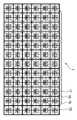
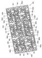
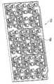
도 2는 본 발명에 따른 듀얼선형편파 혼어레이 안테나의 평면도이고, 도 3 및 도 4는 각각 도 2의 듀얼선형편파 혼어레이 안테나의 배면사시도이다.2 is a plan view of a dual linearly polarized horn array antenna according to the present invention, and FIGS. 3 and 4 are rear perspective views of the dual linearly polarized horn array antenna of FIG. 2, respectively.
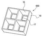
본 듀얼선형편파 혼어레이 안테나(1)는, 전자파가 입사되는 복수의 혼(10)과, 혼(10)의 상부에 결합되어 전자파를 분할하는 격자상의 분할기(70)와, 혼(10)을 통해 입사된 전자파 중 제1편파를 안내하는 제1편파가이드(530)와, 혼(10)을 통해 입사된 전자파 중 제2편파를 안내하는 제2편파가이드(550)를 포함한다.The dual linearly polarized
4개의 혼(10)은 공간을 향해 개방되어 있고, 혼(10)의 하부에는 제1편파가이 드(530)가 형성되고, 제1편파가이드(530)의 하부에는 제2편파가이드(550)가 형성된다. 여기서, 혼(10)과 제1 및 제2편파가이드(530,550)는 전자파가 이동하는 공간이며, 혼(10)과 제1 및 제2편파가이드(530,550)를 형성하기 위한 각 레이어의 형상은 후술하기로 한다.Four
한편, 4개의 혼(10), 제1편파가이드(530) 및 제2편파가이드(550)가 하나의 안테나 단위를 형성하며, 이하에서는 안테나 단위를 기준으로 듀얼선형편파 혼어레이 안테나(1)에 대해 설명하기로 한다. 여기서, 4개의 혼을 각각 제1혼, 제2혼, 제3혼, 제4혼으로 칭한다.Meanwhile, four
도 5는 본 발명의 일 실시예에 따른 듀얼선형편파 혼어레이 안테나의 혼의 정면도, 도 6은 도 5의 혼의 사시도, 도 7은 도 5의 혼의 투시 사시도, 도 8은 도 5의 혼의 투시 측면도, 도 9는 도 5의 혼의 부분 절취사시도이다.5 is a front view of a horn of a dual linearly polarized horn array antenna according to an embodiment of the present invention, FIG. 6 is a perspective view of the horn of FIG. 5, FIG. 7 is a perspective perspective view of the horn of FIG. 5, and FIG. 8 is a perspective side view of the horn of FIG. 5. 9 is a partial cutaway perspective view of the horn of FIG. 5.
상술한 바와 같이, 하나의 안테나 단위는 4개의 혼을 포함하고, 분할기(70)에 의해 각 혼의 외측개구가 4개로 분할되므로, 하나의 안테나 단위에는 16개의 개구가 형성된다.As described above, one antenna unit includes four horns, and since the outer opening of each horn is divided into four by the
혼(10)의 상부에 장착된 분할기(70)는, 격자상으로 배치되는 다수의 리브(75)를 가지며, 하나의 혼(10)의 외측개구에 대해 분할기(70)의 리브(75)가 십자형으로 배치된다. 이에 따라, 혼(10)의 외측개구는 4개의 작은 개구로 분할된다. 이렇게 리브(75)에 의해 혼(10)의 외측개구가 복수개로 분할되면, 안테나의 사이드 로브가 감소되고, 방사 효율이 향상된다.The
혼(10)은 입사면 상에서 상호 직각의 방향을 갖는 제1편파와 제2편파가 입사 되도록 전자파를 안내하며, 사각뿔형상으로 형성된 경사부(15)와, 경사부(15)의 일측 단부에 형성된 편파필터링부(20)를 포함한다.The
경사부(15)는, 전자파의 진행방향을 따라 테이퍼지도록 형성되며, 전자파의 진행방향을 따라 양단이 개방되어 있다. 경사부(15)의 개방된 양단 중 분할기(70)를 향한 개구를 외측개구라 하고, 경사부(15)의 폭이 좁은 내측 일단에 사각형상으로 형성된 개구를 내측개구라 한다. 내측개구에는 그 연부로부터 중앙영역으로 돌출된 돌출턱(17)이 형성되어 있으며, 돌출턱(17)은 내측개구의 둘레를 따라 소정 폭만큼 돌출되어 형성된다. 또한, 편파필터링부(20)의 일측면에도 돌출턱(19)이 형성되어 있으며, 편파필터링부(20)의 돌출턱(19)에 의해 수직편파의 S11 파라미터가 보다 개선되는 효과를 발휘한다.The
도 5 내지 도 9에 도시된 경사부(15)는, 돌출턱(17)이 내측개구를 따라 일정한 폭만큼 돌출되도록 형성함으로써, 내측개구가 사각 형상으로 형성된다.5 to 9, the
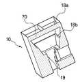
도 10은 본 발명의 다른 실시예에 따른 혼의 부분 절취사시도이다.10 is a partial cutaway perspective view of a horn in accordance with another embodiment of the present invention.
본 실시예에 따른 혼(10)은, 경사부(15)의 경사면을 따라 한 쌍의 돌출턱(18a,18b)이 형성되어 있으며, 이처럼 돌출턱(18a,18b)을 적어도 1개 이상 형성시킴으로써 혼 안테나의 성능이 거의 유지하거나 개선할 수 있으며, 이에 따라, 혼 안테나의 높이를 줄일 수 있다.In the
본 실시예는, 돌출턱(18a,18b)을 2개 가지고 있으나, 이는 어디까지나 예시적인 것이며, 돌출턱(18a,18b)의 개수나, 분할기(70)에 의해 분할되는 개구의 개수는 변경가능함은 물론이다.The present embodiment has two
도 2에 도시된 듀얼선형편파 혼어레이 안테나는, 도 9에 예시된 혼이 채용되어 있으나, 도 10에 예시된 혼 또는 다른 형상이나 사이즈의 혼을 채용할 수도 있음은 물론이다.As the dual linearly polarized horn array antenna illustrated in FIG. 2, the horn illustrated in FIG. 9 is employed, but of course, a horn illustrated in FIG. 10 or a horn of another shape or size may be employed.
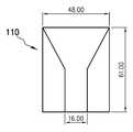
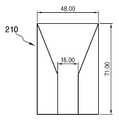
도 11은 본 발명의 일 실시예에 따른 혼의 간략한 측단면도, 도 12는 도 11의 혼과 동일한 크기의 외측개구와 동일한 길이를 갖는 혼의 간략한 측단면도, 도 13은 도 11의 혼과 동일한 성능을 갖는 혼의 간략한 측단면도이다.Figure 11 is a simplified side cross-sectional view of a horn according to an embodiment of the present invention, Figure 12 is a simplified side cross-sectional view of a horn having the same length as the outer opening of the same size as the horn of Figure 11, Figure 13 shows the same performance as the horn of Figure 11 A simple side cross-sectional view of the horn having.
본 발명과 도 12에 도시된 혼(110)의 길이는 61.0mm이고, 도 13에 도시된 혼(210)의 길이는 71.0mm이다. 각 혼(10,110,210)의 외측개구의 폭은 48.0mm로 동일하다. 이러한 세 개의 혼(10,110,210)에 의한 안테나 이득을 위성방송 대역(KU BAND)인 10.7GHz ~ 12.75GHz 중 중심주파수인 11.7GHz, 상측파대의 12.75GHz, 하측파대의 10.7GH에서 비교한 결과가 다음의 표 1에 나타나 있다.The length of the
실험결과에서 볼 수 있는 바와 같이, 본 발명의 혼(10)과, 본 발명의 혼(10)보다 10.0mm가 길게 설계된 도 13의 혼(210)은, 모든 주파수 대역에서 동일한 성능을 나타내고 있다. 그러나, 본 발명의 혼(10)과 동일한 길이와 동일한 외측개구의 크기를 갖는 도 12의 혼(110)은, 본 발명의 혼(10)에 비해, 10.7GHz 대역에서는 0.5dBi, 11.7GHz 대역에서는 0.7dBi, 12.7GHz대역에서는 0.5dBi만큼 안테나 이득이 작음을 알 수 있다. 일반적으로 안테나 이득의 차가 1dBi인 경우 성능이 33%이 향상된다고 볼 수 있으므로, 본 발명의 혼(10)은 동일한 크기의 종래의 혼에 비해 약 18%의 성능이 향상되었음을 알 수 있다. 그리고 동일한 성능을 갖는 도 13의 혼(210)에 비해서, 10mm 정도의 높이를 단축시킬 수 있으므로, 안테나의 크기를 축소시킬 수 있다.As can be seen from the experimental results, the
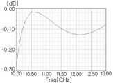
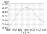
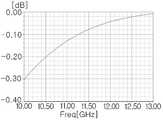
도 14는 도 11의 혼의 S11파라미터를 나타낸 그래프, 도 15는 도 12의 혼의 S11파라미터를 나타낸 그래프, 도 16은 도 13의 혼의 S11파라미터를 나타낸 그래프이다.FIG. 14 is a graph showing S11 parameters of the horn of FIG. 11, FIG. 15 is a graph showing S11 parameters of the horn of FIG. 12, and FIG. 16 is a graph showing S11 parameters of the horn of FIG.
S11파라미터는 안테나로부터 방사된 전자파가 다시 안테나로 되돌아오는 정도를 나타내며, 작을수록 좋고, 일반적으로 -10dB 이하를 만족하면 허용할 수 있는 정도이다.The S11 parameter represents the degree to which the electromagnetic waves radiated from the antenna are returned to the antenna. The smaller the value is, the better it is.
도시된 바와 같이, 본 발명의 혼(10)은 11.6GHz에서 S11파라미터가 -40dB이하이므로, S11파라미터가 양호하다고 볼 수 있다. 이러한 결과는, 12.2GHz에서 S11파라미터가 -50dB로 나타난 도 12의 혼(110)과, 약 11GHz에서 -30dB의 S11파라미터를 나타낸 도 13의 혼(210)에 비해서도 양호한 편임을 알 수 있다.As shown, since the
이와 같이, 경사부(15)의 내측개구에 돌출턱(17)을 형성하면, 내측개구의 폭과 외측개구의 폭을 유지한 상태에서 경사부(15)의 길이를 짧게 형성할 수 있을 뿐만 아니라, 안테나(1)의 이득은 유지시킬 수 있다.As such, when the protruding
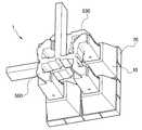
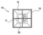
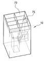
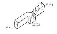
도 17은 편파필터링부의 확대 사시도이다.17 is an enlarged perspective view of the polarization filtering unit.
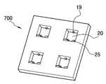
편파필터링부(20)는 경사부(15)의 내측개구에 연결되며, 하나의 안테나 단위에 대해 4개의 편파필터링부(20)가 장착된다. 각 편파필터링부(20)는 혼(10)을 통해 입사된 전자파 중 특정 편파인 제2편파만을 통과시키며, 제1편파는 통과시키지 아니한다. 이에 따라, 제1편파는 편파필터링부(20)를 통과하지 못하여 제1편파가이드(530)로 가이드되며, 제2편파는 편파필터링부(20)의 단차(25)가 있는 영역을 통과하여 제2편파가이드(550)로 가이드된다.The
편파필터링부(20)의 포트1은 혼(10)과 연결되고, 포트2는 제1편파가이드(530)와 연결되며, 포트3은 제2편파가이드(550)와 연결된다.
편파필터링부(20)는 내측개구로부터 제2편파가이드(550)까지 연장되며, 편파필터링부(20)의 일측 면에는 내측개구로부터 일정 구간 동안 복수의 단차(25)가 계단형상으로 형성되어 있다. 이러한 단차(25)에 의해 편파필터링부(20)의 폭이 일측방향으로 좁아지게 되고, 편파필터링부(20)를 통과하는 제1편파와 제2편파가 분리되어 각각 제1편파가이드(530)와 제2편파가이드(550)로 제공된다. 편파필터링부(20)의 넓은 폭과 동일한 전계방향을 갖는 제1편파는 제1편파가이드(530)로 제공되고, 편파필터링부(20)의 좁은 폭과 동일한 전계방향을 갖는 제2편파는 편파필터링부(20)를 따라 이동하여 제2편파가이드(550)로 제공된다. 단차(25)의 갯수와 크기 및 길이는 제2편파가이드(550)로 안내되는 제2편파의 주파수에 따라 변경될 수 있다.The
한편, 단차(25)의 중앙영역에는 제1편파가이드(530)와 연결되는 통로(27)가 형성되어 있다. 통로(27)는 길이방향을 따라 제1편파가이드(530)로 갈수록 단계적으로 넓어지며, 제1편파가이드(530)로 제공되는 제1편파의 주파수에 따라 통로(27)를 형성하는 단계의 폭과 길이 및 높이가 변경될 수 있다.Meanwhile, a
도 18 내지 도 20는 도 17의 편파필터링부의 제1편파의 S파라미터를 나타낸 그래프이다. 여기서, 도 18은 포트1의 S11파라미터이고, 도 19는 포트1과 포트2간의 S21파라미터이고, 도 20은 포트1과 포트3간의 S31파라미터이다.18 to 20 are graphs illustrating S parameters of first polarized waves of the polarization filtering unit of FIG. 17. 18 is an S11 parameter of
도시된 바와 같이, 제1편파에서 S11파라미터는 약 10.7GHz에서 약 -24dB이며, S21파라미터는 S11파라미터와 동일한 주파수대역에서 높게 나타나고 있다. 즉, 제1편파가 포트1에서 입력되어 포트2로 출력되고 있음을 알 수 있다.As shown, the S11 parameter in the first polarization is about -24 dB at about 10.7 GHz, and the S21 parameter is high in the same frequency band as the S11 parameter. That is, it can be seen that the first polarization is input from
도 21 내지 도 23은 도 17의 편파필터링부의 제2편파의 S파라미터를 나타낸 그래프이다. 여기서, 도 21은 포트1의 S11파라미터이고, 도 22는 포트1과 포트2간의 S21파라미터이고, 도 23은 포트1과 포트3간의 S31파라미터이다.21 to 23 are graphs illustrating S parameters of second polarizations of the polarization filtering unit of FIG. 17. Here, FIG. 21 is an S11 parameter of the
도시된 바와 같이, 제2편파에서 S11파라미터는 주파수대역이 높을수록 작아지고 있으며 위성방송의 전영역에 걸쳐 -10dB 이하이다. 그리고, S31파라미터는 주파수대역이 높을수록 커지고 있다. 즉, 제2편파가 포트1에서 입력되어 포트3으로 출력되고 있음을 알 수 있다.As shown, the S11 parameter in the second polarization becomes smaller as the frequency band is higher and is -10 dB or less over the entire area of satellite broadcasting. The S31 parameter is larger as the frequency band is higher. That is, it can be seen that the second polarization is input from
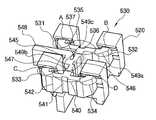
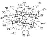
도 24는 도 2의 제1편파가이드와 제2편파가이드가 결합된 사시도, 도 25는 도 24의 제1편파가이드의 사시도, 도 26은 도 24의 제1편파가이드의 평면도, 도 27은 편파필터링부가 제거된 상태의 제1편파가이드의 사시도이다.24 is a perspective view in which the first polarization guide and the second polarization guide of FIG. 2 are coupled, FIG. 25 is a perspective view of the first polarization guide of FIG. 24, FIG. 26 is a plan view of the first polarization guide of FIG. 24, and FIG. 27 is polarization. A perspective view of the first polarization guide in a state where the filtering unit is removed.
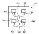
제1편파가이드(530)는, 4개의 혼(10)으로 입사된 제1편파를 안내하여 출사하며, 제1편파가이드(530)의 사방에는 4개의 편파필터링부(20)에 연결되는 4개의 개구(A, B, C, D)가 형성되어 있다. 여기서, 개구A는 제1혼에, 개구B는 제2혼에 연결되며, 개구C는 제3혼에 개구D는 제4혼에 연결된다.The
제1편파가이드(530)는, 각 개구로부터 연장된 제1 내지 제4안내관(531,532,533,534)과, 제1안내관(531)과 제2안내관(532)을 연결하는 제1중개관(535)과, 제3안내관(533)과 제4안내관(534)을 연결하는 제2중개관(540)과, 제1중개관(535)과 제2중개관(540)을 연결하는 제1혼합관(545)과, 제1혼합관(545)으로부터 연장된 배출관(548)을 포함한다.The
제1 내지 제4안내관(531,532,533,534)은, 편파필터링부(20)에 연결되며 각 개구를 통해 제1편파를 제공받는다. 여기서, 개구 A에 연결된 안내관을 제1안내관(531), 개구 B에 연결된 안내관을 제2안내관(532), 개구 C에 연결된 안내관을 제3안내관(533), 개구 D에 연결된 안내관을 제4안내관(534)이라 한다. 각 개구는 동일한 방향을 향해 개방되어 있으며, 제1안내관(531)과 제3안내관(533)이 평행하게 배치되고, 제2안내관(532)과 제4안내관(534)이 평행하게 배치되어 있다.The first to
한편, 제1 내지 제4안내관(531,532,533,534)은 'ㄱ'자 형상으로 형성되며, 제1안내관(531)과 제2안내관(532)은 제1중개관(535)에 대해 대칭으로 형성되고, 제3안내관(533)과 제4안내관(534)은 제2중개관(540)에 대해 대칭으로 형성된다. 이렇게 제1안내관(531)과 제2안내관(532)이 대칭형성되고 제3안내관(533)과 제4안내관(534)이 대칭형성됨에 따라, 제1안내관(531)을 따라 이동하는 제1편파와, 제2안내관(532)을 따라 이동하는 제1편파가 제1중개관(535)에 도달할 때의 위상이 동일해지고, 제3안내관(533)을 따라 이동하는 제1편파와 제4안내관(534)을 따라 이동하는 제1편파가 제2중개관(540)에 도달할 때의 위상이 동일해진다. 이에 따라, 제1안내관(531)과 제2안내관(532)을 따라 안내되어 제1중개관(535)에서 합쳐진 제1편파와, 제3안내관(533)과 제4안내관(534)을 따라 안내되어 제2중개관(540)에서 합쳐진 제1편파가 위상차에 의해 상쇄되거나 변형되는 것을 방지할 수 있다.Meanwhile, the first to
이러한 제1 내지 제4안내관(531,532,533,534)의 절곡영역에는 제1편파의 진행방향을 직각으로 변경시키기 위한 제1경사면(549a)이 비스듬히 형성되어 있다. 개구 A 내지 D로 입사된 제1편파는 각 안내관(531,532,533,534)의 제1경사면(549a)에서 직각으로 반사되어 각각 제1중개관(535) 또는 제2중개관(540)을 향해 진행한다. 다시 말해, 제1안내관(531)과 제2안내관(532)으로 입사된 제1편파는, 각각 제1안내관(531)과 제2안내관(532)을 따라 이동하다가 각각 제1경사면(549a)에 반사되면, 제1중개관(535)을 향해 진행한다. 그리고, 제3안내관(533)과 제4안내관(534)으로 입사된 제1편파는, 각각 제3안내관(533)과 제4안내관(534)을 따라 이동하다가 각각 제1경사면(549a)에 반사되면, 제2중개관(540)을 향해 진행한다.In the bent regions of the first to
도 28은 중개관의 투시 사시도이다.28 is a perspective perspective view of an intermediate tube.
도 27 및 도 28을 참조하면, 제1중개관(535)과 제2중개관(540)은 도 28에 도시된 중개관과 동일한 구조인 'T'자 형상으로 형성되며, 제1중개관(535)은 제1안내관(531), 제2안내관(532), 제1혼합관(545)에 각각 연결되고, 제2중개관(540)은 제3안내관(533), 제4안내관(534), 제1혼합관(545)에 각각 연결된다. 여기서, 제1중개관(535)은 제1안내관(531)과 제2안내관(532)을 따라 이동한 제1편파를 혼합하여 제1혼합관(545)으로 제공하고, 제2중개관(540)은 제3안내관(533)과 제4안내관(534)을 따라 이동한 제1편파를 혼합하여 제1혼합관(545)으로 제공한다. 이러한 제1중개관(535)과 제2중개관(540)은 제1혼합관(545)에 대해 대칭되도록 형성된다.Referring to FIGS. 27 and 28, the first
이러한 제1중개관(535)과 제2중개관(540)은, 제1 내지 제4안내관(531,532,533,534)과 연결되는 영역에서 제1편파의 진행방향을 따라 가로방향 폭이 제1 내지 제4안내관(531,532,533,534)의 폭보다 좁아진다. 이에 따라, 제1중개관(535)과 제1 및 제2안내관(531,532)이 만나는 영역과, 제2중개관(540)과 제3 및 제4안내관(533,534)이 만나는 영역에는 가로방향 폭의 양측에 단차(537,542)가 형성된다. 이러한 단차(537,542)는, 도 28에 도시된 바와 같이, 제1중개관(535)과 제2중개관(540)의 길이방향을 따라 하나만 형성될 수도 있고, 복수개가 형성될 수도 있음은 물론이다.The first
한편, 제1중개관(535)에는 제1안내관(531)과 제2안내관(532)에 의해 안내된 각각의 제1편파가 만나는 영역에, 제1중개관(535)의 내측면에서 제1혼합관(545)을 향해 돌출된 사각기둥형상의 제1돌출부(536)가 형성되어 있다. 마찬가지로, 제2중개관(540)에는 제3안내관(533)과 제4안내관(534)으로부터의 제1편파가 만나는 영역에 제1혼합관(545)을 향해 돌출된 제2돌출부(541)가 형성되어 있다. 제1 및 제2돌출부(536,541)는 제1중개관(535)과 제2중개관(540)의 상부면과 하부면을 연결하도록 상하로 길게 형성된다. 제1돌출부(536)에 의해 제1안내관(531)과 제2안내관(532)으로부터의 제1편파의 전계방향이 90도만큼 변경되고, 전계방향이 변경된 각 제1편파는 상호 합쳐진 다음, 제1혼합관(545)을 향해 이동한다. 마찬가지로, 제2돌출부(541)에 의해 제3안내관(533)과 제4안내관(534)으로부터의 제1편파의 전계방향이 90도만큼 변경되고, 전계방향이 변경된 각 제1편파는 상호 합쳐진 다음, 제1혼합관(545)을 향해 이동한다.On the other hand, in the area where each of the first polarization guided by the
제1혼합관(545)은 'T'자 형상으로 형성되며, 제1중개관(535)과 제2중개관(540)으로부터 제공된 제1편파를 혼합하여 배출관(548)으로 제공한다. 제1혼합관(545)의 제1중개관(535) 및 제2중개관(540)과 연결되는 영역은, 제1편파의 진행방향을 따라 가로방향 폭이 제1중개관(535) 및 제2중개관(540)보다 좁아지며, 이에 따라, 제1혼합관(545)과 제1중개관(535) 및 제2중개관(540)이 연결되는 영역에는 가로방향 폭의 양측에 단차(547)가 형성된다. 또한 제1혼합관(545)의 제1중개관(535)으로부터의 제1편파와 제2중개관(540)으로부터의 제1편파가 합쳐지는 영역에는, 제1혼합관(545)의 내측을 향해 돌출한 제3돌출부(546)가 형성되어 있다. 제3돌출부(546)는 사각기둥형상으로 형성되며, 제1혼합관(545)의 상부면에서 하부면을 연결하도록 상하방향으로 길게 형성된다.The
제1중개관(535)과 제2중개관(540)으로부터의 제1편파는 제3돌출부(546)를 만나면, 전계방향이 90도만큼 변경되고, 전계방향이 변경된 각 제1편파는 상호 합쳐진 다음, 배출관(548)을 향해 진행한다.When the first polarization from the first
배출관(548)은 제1혼합관(545)의 단부로부터 절곡된 다음 다시 외측으로 절곡된 'ㄱ'자 형상으로 형성된다. 제1혼합관(545)과 배출관(548)의 연결영역에는 제1혼합관(545)으로부터의 제1편파를 반사시켜 진행방향을 직각으로 변환하는 제2경사면(549b)이 형성되어 있고, 배출관(548)의 절곡영역에는 제3경사면(549c)이 형성되어 제2경사면(549b)에서 진행방향이 변환된 제1편파의 진행방향을 다시 한번 변환한다. 제1편파는 배출관(548)을 따라 진행하여 안테나 단위로부터 배출된다. 안테나 단위로부터 배출된 제1편파는 타 안테나 단위에서 배출된 제1편파와 혼합되어 외부로 배출되며, 안테나 단위에서 배출된 제1편파의 이동에 대해서는 후술하기로 한다.The
한편, 제1 내지 제3돌출부(536,541,546)의 폭에 따라, 제1 및 제2중개관(535,540)과 제1혼합관(545)에 입사되는 제1편파의 중심 주파수가 결정된다. 즉, 제1 내지 제3돌출부(536,541,546)의 폭을 조절하면, 제1혼합관(545)에 입사되는 제1편파의 중심 주파수를 이동시킬 수 있다.Meanwhile, the center frequencies of the first polarized waves incident on the first and second
한편, 제1혼합관(545)은, 제1중개관(535)과 제2중개관(540)을 통해 입사된 제1편파를 배출관(548) 측으로 모아주거나, 배출관(548)을 통해 입사된 제1편파를 제1중개관(535)과 제2중개관(540)으로 분배하는 역할을 한다. 따라서, 제1혼합관(545)은 입사된 2개의 파를 하나로 모으거나 하나의 파를 두 개로 나누는 기능블럭으로서 임의의 안테나에 장착되어 사용가능하다.Meanwhile, the first
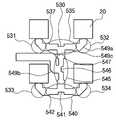
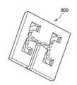
도 29는 도 2의 제2편파가이드의 투시 사시도이고, 도 30은 도 29의 제2편파가이드의 사시도이고, 도 31은 도 29의 제2편파가이드의 평면도이다.29 is a perspective perspective view of the second polarization guide of FIG. 2, FIG. 30 is a perspective view of the second polarization guide of FIG. 29, and FIG. 31 is a plan view of the second polarization guide of FIG. 29.
제2편파가이드(550)는, 제1편파가이드(530)와 평행하게 배치되며, 편파필터링부(20)를 통해 전달된 제2편파를 제공받아 출사한다.The
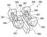
제2편파가이드(550)는, 각 편파필터링부(20)를 통해 전달된 제2편파의 진행방향을 변경하는 제1 내지 제4방향전환부(551,552,553,554)와, 제1방향전환부(551)와 제3방향전환부(553)를 연결하는 제3중개관(555)과, 제2방향전환부(552)와 제4방향전환부(5554)를 연결하는 제4중개관(560)과, 제3중개관(555)과 제4중개관(560)으로부터의 제2편파를 혼합하는 제2혼합관(565)을 포함한다.The
제1 내지 제4방향전환부(551,552,553,554)는, 모서리가 상향 개구된 'ㄱ'자 형상으로 형성되어 각각 편파필터링부(20)와 연결되며, 각 방향전환부(551,552,553,554)에는 돌출단(568)과 반사면(569)이 형성되어 있다. 돌출단(568)은, 각 방향전환부(551,552,553,554)의 편파필터링부(20)를 향한 단부에 각 방향전환부(551,552,553,554)의 바닥면으로부터 상향 돌출형성되며, 제3 및 제4중개관(555,560)의 일자형 관의 길이방향과 평행하게 긴 직육면체 형상으로 형성된다. 편파필터링부(20)의 좁은 폭을 따라 전계방향을 갖는 제2편파는, 돌출단(568)을 만나면 진행방향이 변환된다. 반사면(569)은 돌출단(568)에 대항되는 면에 소정 각도로 비스듬히 형성되며, 돌출단(568)에 의해 진행방향이 변환된 제2편파를 반사하여 제3중개관(555)으로 제공한다.The first to
제1방향전환부(551)와 제2방향전환부(552)는 반사면(569)과 돌출단(568)의 위치가 대응되도록 평행하게 형성되며, 제3방향전환부(553)와 제4방향전환부(554)도 반사면(569)과 돌출단(568)의 위치가 대응되도록 평행하게 형성된다. 그리고, 제1방향전환부(551)와 제3방향전환부(553)의 반사면(569)은 상호 대칭되어 형성되며, 제2방향전환부(552)와 제4방향전환부(554)의 반사면(569)도 상호 대칭되어 형성된다.The
제3중개관(555)과 제4중개관(560)은, 제1중개관(535) 및 제2중개관(540)과 마찬가지로 'T'자 형상으로 형성되며, 제3중개관(555)은 제1방향전환부(551), 제3방향전환부(553), 제2혼합관(565)에 각각 연결되고, 제4중개관(560)은 제2방향전환부(552), 제4방향전환부(554), 제2혼합관(565)에 각각 연결된다. 여기서, 제3중개관(555)은 제1방향전환부(551)와 제3방향전환부(553)에서 진행방향이 변환된 제2편파를 혼합하여 제2혼합관(565)으로 제공하고, 제4중개관(560)은 제2방향전환부(552)와 제4방향전환부(554)에서 진행방향이 변환된 제2편파를 혼합하여 제2혼합관(565)으로 제공한다. 이러한 제3중개관(555)과 제4중개관(560)은 제2혼합관(565)에 대해 대칭되도록 형성된다.The third
한편, 제3중개관(555)과 제4중개관(560)은, 제1 내지 제4방향전환부(551,552,553,554)와 연결되는 영역에서 제2편파의 진행방향을 따라 가로방향 폭이 제1 내지 제4방향전환부(551,552,553,554)의 폭보다 좁다. 이에 따라, 제3중개관(555)과 제1 및 제3방향전환부(551,553)가 만나는 영역과, 제4중개관(560)과 제2 및 제4방향전환부(552,554)가 만나는 영역에는 가로방향 폭의 양측에 단차(557,562)가 형성된다. 이러한 단차(557,562)는, 제3중개관(555)과 제4중개관(560)의 길이방향을 따라 하나만 형성될 수도 있고, 복수개가 형성될 수도 있음은 물론이다.On the other hand, the third
이러한 제3중개관(555)과 제4중개관(560)에는 일자형 관의 중앙영역에 분기관을 향해 돌출된 사각기둥형상의 제4돌출부(556) 및 제5돌출부(561)가 형성되어 있다. 제4 및 제5돌출부(556,561)는 제3중개관(555)과 제4중개관(560)의 상부면과 하부면을 연결하도록 상하방향으로 길게 형성된다. 제4돌출부(556)에 의해 제1방향전환부(551)와 제3방향전환부(553)로부터의 제2편파의 전계방향이 90도만큼 변경되고, 전계방향이 변경된 각 제2편파는 상호 합쳐진 다음, 제2혼합관(565)을 향해 이동한다. 마찬가지로, 제5돌출부(561)에 의해 제2방향전환부(552)와 제4방향전환부(554)로부터의 제2편파의 전계방향이 90도만큼 변경되고, 전계방향이 변경된 각 제2편파는 상호 합쳐진 다음, 제2혼합관(565)을 향해 이동한다.The third
제2혼합관(565)은 'T'자 형상으로 형성되며, 제3중개관(555)과 제4중개관(560)으로부터 제공된 제2편파를 혼합하여 타 안테나 단위로부터의 제2편파와 혼합되도록 배출된다. 이러한 제2혼합관(565)의 제3중개관(555) 및 제4중개관(560)과 연결되는 영역은, 제2편파의 진행방향을 따라 가로방향 폭이 제3중개관(555) 및 제4중개관(560)보다 좁아지며, 이에 따라, 제2혼합관(565)의 제3중개관(555) 및 제4중개관(560)이 연결되는 영역에는 가로방향 폭의 양측에 단차(567)가 형성된다. 또한 제2혼합관(565)의 제3중개관(555)으로부터의 제2편파와 제4중개관(560)으로부터의 제2편파가 합쳐지는 영역에는, 제2혼합관(565)의 내측을 향해 돌출한 제6돌출부(566)가 형성되어 있다. 제6돌출부(566)는 사각기둥형상으로 형성되며, 제2혼합관(565)의 상부면에서 하부면까지 연장되도록 길게 형성된다.The
제3중개관(555)과 제4중개관(560)으로부터의 제2편파는 제6돌출부(566)를 만나면, 전계방향이 90도만큼 변경되고, 전계방향이 변경된 각 제2편파는 상호 합쳐진 다음 배출된다. 여기서, 제4 내지 제6돌출부(566)의 두께와 길이 및 반사면의 폭과 높이에 따라, 제2편파가이드(550)의 입사 및 출사되는 제2편파의 주파수를 조절할 수 있다.When the second polarization from the third
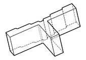
도 32는 본 발명의 다른 실시예에 따른 T형 분배관의 투시 사시도이다.32 is a perspective view of a T-type distribution tube according to another embodiment of the present invention.
제1 내지 제4중개관(535,540,555,560)과, 제1 및 제2혼합관(545,565)은 동일한 형상으로 형성되며, 다만 각 중개관(535,540,555,560)과 각 혼합관(545,565)의 폭이 다소 상이하다. 따라서, 도 32에 도시된 T형 분배관은, 제1 내지 제4중개관(535,540,555,560) 뿐만 아니라, 제1 및 제2혼합관(545,565)으로 사용할 수 있다.The first to fourth
T형 분배관이 일자형 관과, 일자형 관의 중앙영역에서 분기된 분기관으로 형성된다고 볼 때, 본 실시예에 따른 T형 분배관은, 일자형 관에는 길이방향을 따라 중앙영역으로 갈수록 그 폭이 단계적으로 감소하여 단차가 형성되어 있다. 이 때, 단차는 일자형 관의 길이방향을 따라 분기관이 결합되지 아니하는 타측면에만 형성된다.Considering that the T-shaped distribution pipe is formed of a straight pipe and a branch pipe branched from the central area of the straight pipe, the T-shaped distribution pipe according to the present embodiment has a width in the straight pipe as it goes toward the central area along the longitudinal direction. It decreases in steps and a step is formed. At this time, the step is formed only on the other side where the branch pipe is not coupled along the longitudinal direction of the straight pipe.
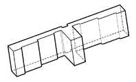
도 33은 본 발명의 또 다른 실시예에 따른 T형 분배관의 투시 사시도이다.33 is a perspective view of a T-type distribution tube according to another embodiment of the present invention.
도 33에 도시된 T형 분배관에는, 일자형 관의 길이방향을 따라 복수의 단차가 형성되며, 이 때, 일자형 관의 분기관이 결합된 일측면에만 단차가 형성되어 있다.In the T-shaped distribution pipe shown in FIG. 33, a plurality of steps are formed along the longitudinal direction of the straight pipe, and at this time, a step is formed only on one side to which the branch pipe of the straight pipe is coupled.
도 32 및 도 33에 도시된 T형 분배관은 각각 복수의 단차가 형성되어 있으나, 하나의 단차가 형성될 수도 있음은 물론이다. 또한, T형 분배관의 분기관에는 단차가 형성되어 있지 아니하나, 도 34에 도시된 바와 같이, 분기관의 길이방향을 따라 자유단부로 갈수록 좁아지도록 단차를 형성할 수도 있음은 물론이다. 이렇게 분기관에 단차를 형성하는 것은, 일자형 관에 비해 늘어난 분기관의 폭을 원래의 크기로 감소시키기 위한 것으로서, 복수의 단차를 형성함으로써 관의 폭 축소에 따른 손실을 최소화할 수 있다.32 and 33 each of the T-type distribution pipe is formed with a plurality of steps, of course, one step may be formed. In addition, although the step is not formed in the branch pipe of the T-type distribution pipe, as shown in FIG. 34, the step may be formed so as to become narrower toward the free end along the longitudinal direction of the branch pipe. Forming a step in the branch pipe is to reduce the width of the branch pipe increased compared to the straight pipe to its original size, it is possible to minimize the loss due to the narrowing of the pipe width by forming a plurality of steps.
상술한 구성에 의한 듀얼선형편파 혼어레이 안테나(1)에서 제1편파와 제2편파가 분리되어 수신되는 과정을 살펴보면 다음과 같다.The process of receiving the first polarized wave and the second polarized wave separately from the dual linearly polarized
먼저, 혼(10)을 통해 전자파가 입사되면, 전자파는 경사부(15)를 따라 안내된 다음, 돌출턱(17)을 거쳐 편파필터링부(20)로 제공된다. 편파필터링부(20)는 복수의 단차(25)에 의해 일측의 폭이 점차 좁아지며, 이에 따라, 편파필터링부(20)의 긴 폭과 동일한 전계방향을 갖는 제1편파는 편파필터링부(20)를 통과하지 못하고 편파필터링부(20)의 제1편파가이드(530)를 향한 개구를 통해 제1편파가이드(530)로 입사된다. 그리고, 편파필터링부(20)의 짧은 폭과 동일한 전계방향을 갖는 제2편파는 편파필터링부(20)를 따라 하향 이동하여 제2편파가이드(550)로 입사된다.First, when an electromagnetic wave is incident through the
4개의 혼(10)을 통해 입사된 전자파 중 제1편파는 제1편파가이드(530)의 제1 내지 제4안내관(531,532,533,534)의 각 개구로 입사된다. 제1중개관(535)에서는 제1안내관(531)과 제2안내관(532)으로부터의 제1편파가 제1돌출부(536)에 의해 전계방향이 90도만큼 변경된 다음, 상호 혼합된다. 제2중개관(540)에서는 제3안내관(533)과 제4안내관(534)으로부터의 제1편파가 제2돌출부(541)에 의해 전계방향이 90도만큼 변경된 다음, 상호 혼합된다. 제1중개관(535) 및 제2중개관(540)으로부터의 제1편파는 제1혼합관(545)으로 안내된다. 제1혼합관(545)에서는 제1중개관(535) 및 제2중개관(540)으로부터의 제1편파가 제3돌출부(546)에 의해 전계방향이 90도만큼 변경된 다음, 상호 혼합되고, 배출관(548)을 통해 이동하여 출사된다.The first polarized wave among the electromagnetic waves incident through the four
한편, 편파필터링부(20)를 통해 제2편파가이드(550)로 안내된 제2편파는, 편파필터링부(20)의 좁은 폭과 동일한 전계방향을 갖는다. 제2편파는 각각 제1 내지 제4방향전환부(551,552,553,554)로 이동하고, 제1 내지 제4방향전환부(551,552,553,554)에 형성된 돌출단(568)을 만나서 진행방향이 변환된다. 제2편파는 제1 내지 제4방향전환부(551,552,553,554)의 반사면(569)에서 반사되어 각각 제3 또는 제4중개관(555,560)으로 이동하며, 제4 및 제5돌출부(556,561)에서 합쳐진 다음, 제2혼합관(565)으로 이동한다. 제2혼합관(565)의 제6돌출부(566)에서는 제3 및 제4중개관(555,560)으로부터의 제2편파가 합쳐지며, 합쳐진 제2편파는 제2혼합관(565)을 따라 이동하여 출사된다.On the other hand, the second polarization guided to the
한편, 듀얼선형편파 혼어레이 안테나(1)에서 제1편파와 제2편파가 송신되는 과정을 살펴보면 다음과 같다.Meanwhile, the process of transmitting the first polarized wave and the second polarized wave in the dual linearly polarized
제2편파가이드(550)의 제2혼합관(565)으로 입사된 제2편파는 제6돌출부(566)에 의해 분리되어 제3 및 제4중개관(560)으로 안내된다. 제3 및 제4중개관(555,560)에서는 각각 제4 및 제5돌출부(561)에 의해 제2편파가 다시 한번 분리되고, 분리된 편파는 각 방향전환부(551,552,553,554)의 반사면(569)에서 반사되어 각각 돌출단(568)으로 제공된다. 제2편파는, 각 돌출단(568)에 의해 진행방향이 편파필터링부(20)쪽으로 변경되고, 편파필터링부(20)를 통해서 상승한다.The second polarization incident on the
한편, 제1편파가이드(530)의 배출관(548)을 통해 제1혼합관(545)으로 입사된 제1편파는, 제3돌출부(546)에서 분리되어 각각 제1 및 제2중개관(535,540)으로 전달된다. 제1 및 제2중개관(535,540)에서는 제1 및 제2돌출부(536,541)에서 제1편파의 진행방향이 각 안내관(531,532,533,534)을 향해 변경되고, 각 제1경사면(549a)에 의해 반사되어 각 개구로 제1편파가 진행된다. 각 개구를 통해 각 편파필터링부(20)로 출사된 제1편파는 제2편파가이드(550)로부터의 제2편파와 합쳐져 경사부(15)를 통해 공중으로 방사된다.On the other hand, the first polarization incident to the
이러한 듀얼선형편파 혼어레이 안테나(1)를 제작하기 위한 구성을 안테나 단위로 살펴보면 다음과 같다.Looking at the configuration for manufacturing the dual linearly polarized horn array antenna (1) as an antenna unit as follows.
도 35는 본 발명에 따른 듀얼선형편파 혼어레이 안테나의 각 레이어 분해사시도이고, 도 36은 도 35의 제1레이어의 평면도, 도 37은 제1레이어의 사시도이다.35 is an exploded perspective view of each layer of the dual linearly polarized horn array antenna according to the present invention, FIG. 36 is a plan view of the first layer of FIG. 35, and FIG. 37 is a perspective view of the first layer.
본 듀얼선형편파 혼어레이 안테나는, 제1레이어(600), 제2레이어(650), 제3레이어(700), 제4레이어(750), 제5레이어(800)로 이루어진다.The dual linearly polarized horn array antenna includes a
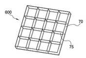
제1레이어(600)는 분할기(70)로 형성되며, 행렬로 배치된 다수의 리브(75)를 갖는 분할기(70)가 제1레이어(600)로 형성된다. 하나의 안테나 단위에 대해, 제1레이어(600)의 분할기(70)는 16개의 구역으로 분할되도록 리브(75)가 배치된다.The
도 38은 도 35의 제2레이어의 사시도, 도 39은 제2레이어의 평면도, 도 40은 제2레이어의 배면도이다.FIG. 38 is a perspective view of the second layer of FIG. 35, FIG. 39 is a plan view of the second layer, and FIG. 40 is a rear view of the second layer.
제2레이어에는 혼(10)의 경사부(15)와 돌출턱(17)이 형성되어 있으며, 제1레이어(600)의 평면 측에는 경사부(15)가 형성되고, 제1레이어(600)의 배면 측에는 내측개구가 형성된다.An
도 41은 도 35의 제3레이어의 사시도, 도 42는 제3레이어의 평면도, 도 43은 제3레이어의 배면도이다.FIG. 41 is a perspective view of the third layer of FIG. 35, FIG. 42 is a plan view of the third layer, and FIG. 43 is a rear view of the third layer.
제3레이어(700)에는 제2레이어(650)에 형성된 내측개구와 연결되는 편파필터링부(20)가 형성되고, 편파필터링부(20)는 제2레이어(650)의 각 모서리에 인접한 영역을 관통하여 형성된다. 편파필터링부(20)의 내측에는 단차(25)와 돌기(19)가 형성되어 있다.The
제3레이어(700)의 배면에는 제1편파가이드(530)의 제1 내지 제4안내관(531,532,533,534), 제1 및 제2중개관(535,540), 제1혼합관(545), 배출관(548)의 상측 부분이 형성된다.The first to
도 44는 도 35의 제4레이어의 사시도, 도 45는 제4레이어의 평면도, 도 46은 제4레이어의 배면도이다.44 is a perspective view of the fourth layer of FIG. 35, FIG. 45 is a plan view of the fourth layer, and FIG. 46 is a rear view of the fourth layer.
제4레이어(750)의 상면에는 제1편파가이드(530)의 하부영역이 형성되고, 제4레이어(750)의 하면에는 제2편파가이드(550)의 상부영역이 형성되며, 제4레이어(750)를 관통하여 편파필터링부(20)가 형성된다.A lower region of the
즉, 제4레이어(750)의 상면에는 제1편파가이드(530)의 제1 내지 제4안내관(531,532,533,534), 제1 및 제2중개관(535,540), 제1혼합관(545), 배출관(548)의 하측 부분이 형성된다. 그리고 제4레이어(750)의 하면에는 제2편파가이드(550)의 제3 및 제4중개관(555,560), 제2혼합관(565)의 상측 부분이 형성된다.That is, on the upper surface of the
도 47은 제5레이어의 사시도, 도 48은 제5레이어의 평면도이다.47 is a perspective view of the fifth layer, and FIG. 48 is a plan view of the fifth layer.
제5레이어(800)에는 제2편파가이드(550)의 하측 영역이 형성된다. 제5레이어(800)는 제4레이어(750)와 함께 제2편파가이드(550)를 형성하며, 제1 내지 제4방향전환부(551,552,553,554), 제3 및 제4중개관(555,560), 제2혼합관(565)이 형성되어 있다. 그리고 제5레이어(800)의 제1 내지 제4방향전환부(551,552,553,554)내에는 각 돌출단(568)과 반사면(569)이 형성되어 있다.The lower region of the
도 49는 본 발명에 따른 혼어레이 안테나의 사용예의 사시도, 도 50는 도 49의 혼어레이 안테나의 평면도, 도 51은 제1레이어의 사시도, 도 52는 제2레이어의 사시도이다.49 is a perspective view of a usage example of the horn array antenna according to the present invention, FIG. 50 is a plan view of the horn array antenna of FIG. 49, FIG. 51 is a perspective view of the first layer, and FIG. 52 is a perspective view of the second layer.
본 사용예의 혼어레이 안테나는, 가로×세로 혼의 갯수가 6×12=72개인 경우, 즉, 3×6=18개의 안테나 단위로 이루어진다. 이에 따라, 도 51의 제1레이어(600)에 형성된 분할기(70)는, 12×24=288개의 개구가 형성되고, 도 52의 제2레이어(650)에는 72개의 혼(10)이 형성된다.The horn array antenna of this use example is composed of 6x12 = 72 horns, that is, 3x6 = 18 antenna units. Accordingly, in the
도 53은 도 49의 혼어레이 안테나의 제3레이어의 평면사시도, 도 54는 도 49의 제3레이어의 배면사시도, 도 55는 도 49의 제4레이어의 평면사시도이다.FIG. 53 is a plan perspective view of the third layer of the horn array antenna of FIG. 49, FIG. 54 is a rear perspective view of the third layer of FIG. 49, and FIG. 55 is a plan perspective view of the fourth layer of FIG. 49.
본 실시예의 혼어레이 안테나는 18개의 안테나 단위로 이루어지며, 제3레이어(700)의 배면과 제4레이어(750)의 평면에는 18개의 제1편파가이드(530)가 형성되어 있다. 여기서, 제1편파가이드(530)는 행방향과 열방향을 따라 개수의 비율이 1:2 또는 2:1이 되도록 배치된다. 즉, 제1편파가이드(530)는 3의 배수로 배치되며, 이에 따라, 제1편파가이드(530)는 행방향을 따라 3의 배수인 3개가 배치되고, 열방향을 따라 3의 배수인 6개가 배치된다. 각 제1편파가이드(530)로부터 출사된 제1편파는 하나의 제1편파로 혼합되어 혼어레이 안테나의 외부로 출사된다. 이를 위해 제3레이어(700)의 저면에는 제1편파가이드 7(530g)과 제1편파가이드 8(530h) 사이에 상하경사면(730)이 형성되어 있으며, 상하경사면(730)에 의해 제1편파는 제4레이어(750)에 형성된 제1편파 메인개구(755)를 통해 이동한다.The horn array antenna according to the present exemplary embodiment includes 18 antenna units, and 18 first polarization guides 530 are formed on the rear surface of the
제1편파가이드 1(530a)과 제1편파가이드 2(530b)는 상호 대칭되도록 형성되며, 제1편파가이드 1(530a)의 배출관(548)과 제1편파가이드 2(530b)의 배출관(548)의 단부에는 'T'자 형상의 제1대칭분배관-1(701)이 형성되어 있다. 제1대칭분배관-1(701)의 단부는 제1편파가이드 2(530b)를 둘러싸도록 연장형성되어 있다. 이에 따라, 제1편파가이드 1(530a)과 제1편파가이드 2(530b)로부터의 제1편파가 상호 혼합되며, 혼합된 제1편파는 제1대칭분배관-1(701)을 따라 이동한다.The first polarization guide 1 (530a) and the first polarization guide 2 (530b) are formed to be symmetrical with each other, the
이러한 제1대칭분배관-1(701)과, 후술할 제2 내지 제14대칭분배관-1(702~714)은, 모두 'T'자 형상으로 형성되며, 일자형 관의 양단부를 포트1과 포트2라 하고, 분기관의 단부를 포트3이라 하면, 포트1과 포트2의 폭이 포트1과 포트2에 결합된 각 배출관(548) 또는 타 대칭분배관-1(701~714)의 분기관의 폭보다 좁아지도록 형성된다. 이에 따라, 각 대칭분배관-1(701~714)의 포트1과 포트2 영역에는 단차가 형성된다.The first symmetric distribution pipe-1 (701) and the second to fourteenth symmetric distribution pipe-1 (702 to 714), which will be described later, are all formed in a 'T' shape, and both ends of the straight pipe are connected to the
제1편파가이드 3(530c)과 제1편파가이드 4(530d)는 상호 대칭되도록 형성되며, 제1편파가이드 3(530c)의 배출관(548)과 제1편파가이드 4(530d)의 배출관(548)의 단부에는 'T'자 형상의 제2대칭분배관-1(702)이 형성되어 있다. 이에 따라, 제1편파가이드 3(530c)과 제1편파가이드 4(530d)로부터의 제1편파가 제2대칭분배관-1(702)에서 상호 혼합된다.The first polarization guide 3 (530c) and the first polarization guide 4 (530d) is formed to be symmetrical with each other, the
제1편파가이드 5(530e)와 제1편파가이드 6(530f)도 상호 대칭되도록 형성되며, 제1편파가이드 3(530c) 및 제1편파가이드 4(530d)와는 상호 평행하도록 형성된다. 제1편파가이드 5(530e)의 배출관(548)과 제1편파가이드 6(530f)의 배출관(548)의 단부는 제3대칭분배관-1(703)에 의해 연결되어 있다. 이에 따라, 제1편파가이드 5(530e)와 제1편파가이드 6(530f)으로부터의 제1편파가 제3대칭분배관-1(703)에서 상호 혼합된다.The first polarization guide 5 (530e) and the first polarization guide 6 (530f) are also formed to be symmetrical with each other, and are formed parallel to the first polarization guide 3 (530c) and the first polarization guide 4 (530d). The end of the
제2대칭분배관-1(702)과 제3대칭분배관-1(703)의 단부는 제4대칭분배관-1(704)에 의해 결합되며, 제4대칭분배관-1(704)의 분기관은 제1편파가이드 4(530d)를 둘러싸도록 연장되어 제1대칭분배관-1(701)을 향한다.Ends of the second symmetric distribution pipe-1 (702) and the third symmetric distribution pipe-1 (703) are coupled by the fourth symmetric distribution pipe-1 (704), and the fourth symmetric distribution pipe-1 (704) The branch pipe extends to surround the first polarization guide 4 (530d) and faces the first symmetric distribution pipe-1 (701).
제1대칭분배관-1(701)과 제4대칭분배관-1(704)의 각 단부에는 제1비대칭 분배관(721)에 의해 상호 연결된다. 제1비대칭 분배관(721)은, 도 56에 도시된 바와 같이, 제1대칭분배관-1(701)에 연결되는 포트1은 복수의 단차가 형성되어 그 폭이 점차 좁아지도록 형성되고, 제4대칭분배관-1(704)에 연결되는 포트2에는 제1편파를 반사시키기 위한 안내면이 형성되어 있다. 이 때, 제1대칭분배관-1(701)으로부터 제공되는 제1편파는 제1편파가이드 1(530a)과 제1편파가이드 2(530b)로부터 이동된 것이고, 제4대칭분배관-1(704)으로부터 제공되는 제1편파는 제1편파가이드 3 내지 6(530c~530f)으로부터 이동된 것이다. 즉, 제1비대칭 분배관(721)에는 제1대칭분배관-1(701)으로부터 2만큼의 제1편파가 포트1로 입사되고 제4대칭분배관-1(704)으로부터 4만큼의 제1편파가 포트2로 입사되므로, 포트1과 포트2로 1:2의 제1편파가 입사되어 혼합된다.Each end of the first symmetric distribution pipe-1 (701) and the fourth symmetric distribution pipe-1 (704) is connected to each other by a first asymmetric distribution pipe (721). As illustrated in FIG. 56, the first
제1편파가이드 7(530g) 내지 12(530l)와, 제1편파가이드 13(530m) 내지 18(530r)은, 제1편파가이드 1(530a) 내지 6(530f)과 거의 유사한 배치를 가지고 상호 평행하게 제3레이어(700)의 배면과 제4레이어(750)의 평면에 배치된다.The first polarization guides 7 (530g) to 12 (530l) and the first polarization guides 13 (530m) to 18 (530r) have substantially similar arrangements to the first polarization guides 1 (530a) to 6 (530f). The rear surface of the
제1편파가이드 7(530g)의 배출관(548)과 제1편파가이드 8(530h)의 배출관(548)은 제5대칭분배관-1(705)에 의해 상호 연결되고, 제5대칭분배관-1(705)은 제1편파가이드 8(530h)의 둘레를 감싸도록 연장된다. 이에 따라, 제1편파가이드 7(530g)과 제1편파가이드 8(530h)로부터의 제1편파는 제5대칭분배관-1(705)에서 상호 혼합된 다음 제5대칭분배관-1(705)을 따라 이동한다.The
제1편파가이드 9(530i)의 배출관(548)과 제1편파가이드 10(530j)의 배출관(548)은 제6대칭분배관-1(706)에 의해 상호 연결되고, 제1편파가이드 11(530k)의 배출관(548)과 제1편파가이드 12(530l)의 배출관(548)은 제7대칭분배관-1(707)에 의해 상호 연결된다. 그리고 제6대칭분배관-1(706)과 제7대칭분배관-1(707)은 제1편파가이드 10(530j)과 제1편파가이드 12(530l) 사이에 배치된 제8대칭분배관-1(708)에 의해 상호 연결된다. 따라서, 제1편파가이드 9(530i)와 제1편파가이드 10(530j)으로부터의 제1편파는 제6대칭분배관-1(706)에서 상호 혼합되고, 제1편파가이드 11(530k)과 제1편파가이드 12(530l)로부터의 제1편파는 제7대칭분배관-1(707)에서 상호 혼합된다. 그런 다음, 제6대칭분배관-1(706)과 제7대칭분배관-1(707)으로부터의 제1편파는 제8대칭분배관-1(708)에 의해 혼합되어 이동한다.The
한편, 제1편파가이드 13(530m)의 배출관(548)과 제1편파가이드 14(530n)의 배출관(548)은 제9대칭분배관-1(709)에 의해 상호 연결되고, 제1편파가이드 13(530m)과 제1편파가이드 14(530n)로부터의 제1편파는 제9대칭분배관-1(709)에서 상호 혼합된다. 이러한 제9대칭분배관-1(709)은 제1편파가이드 13(530m)의 둘레를 감싸도록 연장된다. 제1편파가이드 8(530h)과 제1편파가이드 13(530m) 사이에는 제13대칭분배관-1(713)이 형성되어 제5대칭분배관-1(705)과 제9대칭분배관-1(709)을 연결하고, 제1편파가이드 8(530h)과 제1편파가이드 13(530m)으로부터의 제1편파는 제13대칭분배관-1(713)에서 혼합된다.On the other hand, the
제1편파가이드 15(530o)의 배출관(548)과 제1편파가이드 16(530p)의 배출관(548)은 제10대칭분배관-1(710)에 의해 상호 연결되며, 제1편파가이드 15(530o)와 제1편파가이드 16(530p)으로부터의 제1편파는 제10대칭분배관-1(710)에서 상호 혼합된다. 제1편파가이드 17(530q)의 배출관(548)과 제1편파가이드 18(530r)의 배출관(548)은 제11대칭분배관-1(711)에 의해 상호 연결되며, 제1편파가이드 17(530q)과 제1편파가이드 18(530r)로부터의 제1편파는 제11대칭분배관-1(711)에 의해 상호 혼합된다.The
그리고 제10대칭분배관-1(710)과 제11대칭분배관-1(711)은 제1편파가이드 15(530o) 내지 18의 중앙영역에 배치된 제12대칭분배관-1(712)에 의해 상호 연결되며, 제10대칭분배관-1(710)과 제11대칭분배관-1(711)으로부터의 제1편파는 제12대칭분배관-1(712)에서 혼합된다.The tenth symmetrical distribution pipe-1 (710) and the eleventh symmetrical distribution pipe-1 (711) are arranged in the twelfth symmetrical distribution pipe-1 (712) disposed in the central region of the first polarization guide 15 (530o) to 18. Interconnected by the first symmetric distribution pipe-1 710 and the first polarization from the 11th symmetric distribution pipe-1 711 are mixed in the 12th symmetric distribution pipe-1 712.
제12대칭분배관-1(712)과 제8대칭분배관-1(708)은 상호 상대방 측으로 연장되어 제14대칭분배관-1(714)에 의해 연결되고, 제12대칭분배관-1(712)과 제8대칭분배관-1(708)으로부터 제1편파는 제14대칭분배관-1(714)에서 혼합된다.The 12th symmetrical distribution pipe-1-712 and the 8th symmetrical distribution pipe-1-708 are extended to the other side and connected by the 14th symmetrical distribution pipe-1-714, and the 12th symmetrical distribution pipe-1 ( 712 and the first polarization from the eighth symmetric distribution pipe-1 708 are mixed in the fourteenth symmetric distribution pipe-1 714.
한편, 제13대칭분배관-1(713)과 제14대칭분배관-1(714)은 상대방 측을 향해 연장되고 제2비대칭 분배관(722)에 의해 결합된다. 제2비대칭 분배관(722)은 제1비대칭 분배관(721)과 마찬가지로, 제13대칭분배관-1(713)에 연결되는 포트1은 복수의 단차가 형성되어 그 폭이 점차 좁아지도록 형성되고, 제14대칭분배관-1(714)에 연결되는 포트2에는 제1편파를 반사시키기 위한 경사면이 형성되어 있다. 이 때, 제13대칭분배관-1(713)으로부터 제공되는 제1편파는 제1편파가이드 7(530g) 및 8과 제1편파가이드 13(530m) 및 14(530n)로부터 이동된 것이고, 제14대칭분배관-1(714)으로부터 제공되는 제1편파는 제1편파가이드 9(530i) 내지 12(530l)와 제1편파가이드 15(530o) 내지 18(530r)로부터 이동된 것이다. 즉, 제2비대칭 분배관(722)에는 제13대칭분배관-1(713)으로부터 4만큼의 제1편파가 입사되고 제14대칭분배관-1(714)으로부터 8만큼의 제1편파가 입사되므로, 포트1과 포트2로 1:2의 제1편파가 입사된 다음 혼합되어 배출된다.On the other hand, the thirteenth symmetric distribution pipe-1 713 and the fourteenth symmetric distribution pipe-1 714 extend toward the other side and are coupled by the second
이러한 제1비대칭 분배관(721)과 제2비대칭 분배관(722)은, 그 분기관이 상호 상대방 측을 향해 연장되며, 그 단부는 제3비대칭 분배관(723)에 의해 연결된다. 제3비대칭 분배관(723)은, 제1비대칭 분배관(721)에 연결되는 포트1은 복수의 단차가 형성되어 그 폭이 점차 좁아지도록 형성되고, 제2비대칭 분배관(722)에 연결되는 포트2에는 제1편파를 반사시키기 위한 안내면이 비스듬히 형성되어 있다. 이 때, 제1비대칭 분배관(721)으로부터 제공되는 제1편파는 제1편파가이드 1 내지 6(530a~530f)으로부터 이동된 것이고, 제2비대칭 분배관(722)으로부터 제공되는 제1편파는 제1편파가이드 7 내지 18(530g~530r)로부터 이동된 것이다. 즉, 제3비대칭 분배관(723)에는 제1비대칭 분배관(721)으로부터 6만큼의 제1편파가 입사되고 제2비대칭 분배관(722)으로부터 12만큼의 제1편파가 입사되므로, 포트1과 포트2로 1:2의 제1편파가 입사된 다음 혼합된다. 혼합된 제1편파는 제1편파가이드 7(530g)과 제1편파가이드 8(530h) 사이에 형성된 상하경사면(730)에 의해 반사되어 제4레이어(750)에 형성된 제1편파 메인개구(755)로 안내된다.In such a first
도 57은 도 49의 혼어레이 안테나의 제4레이어의 배면사시도, 도 58은 도 49의 제5레이어의 평면사시도, 도 59는 도 49의 제5레이어의 배면사시도이다.FIG. 57 is a rear perspective view of the fourth layer of the horn array antenna of FIG. 49, FIG. 58 is a top perspective view of the fifth layer of FIG. 49, and FIG. 59 is a rear perspective view of the fifth layer of FIG. 49.
본 실시예의 혼어레이 안테나가 18개의 안테나 단위로 이루어짐에 따라, 제4레이어(750)의 저면과 제5레이어(800)의 상면에는 18개의 제2편파가이드(550)가 형성되어 있다. 각 제2편파가이드(550)로부터 출사된 제2편파는 하나의 제2편파로 혼합되어 혼어레이 안테나의 외부로 출사된다. 이를 위해 제5레이어(800)에는 제2편파가이드 8(550h)과 제2편파가이드 10(550j) 사이에 제5레이어(800)를 관통하는 제2편파 메인개구(855)가 형성되어 있다.As the horn array antenna according to the present exemplary embodiment includes 18 antenna units, 18 second polarization guides 550 are formed on the bottom surface of the
제2편파가이드 1(550a)과 제2편파가이드 2(550b)는 상호 대칭되도록 형성되며, 제2편파가이드 1(550a)의 제2혼합관(565)과 제2편파가이드 2(550b)의 제2혼합관(565)은 그 단부가 각각 상호 상대방을 향해 'ㄱ'자 형상으로 절곡되어 연장되고, 그 단부에는 'T'자 형상의 제1대칭분배관-2(801)이 연결되어 있다.The second polarization guide 1 (550a) and the second polarization guide 2 (550b) are formed to be symmetrical with each other, the
이러한 제1대칭분배관-2(801)과, 후술할 제2 내지 제14대칭분배관-2(802~814)은, 모두 'T'자 형상으로 형성되며, 일자형 관의 양단부를 포트1과 포트2라 하고, 분기관의 단부를 포트3 라 하면, 포트1과 포트2의 폭이 포트1과 포트2에 결합된 각 제2혼합관(565) 또는 타 대칭분배관-2(801~814)의 분기관 폭보다 좁게 형성된다. 이에 따라, 각 대칭분배관-2(801~814)의 포트1과 포트2 영역에는 단차가 형성된다.The first symmetric distribution pipe-2 (801) and the second to fourteenth symmetric distribution pipe-2 (802 to 814) to be described later are all formed in a 'T' shape, both ends of the straight pipe and
제2편파가이드 3(550c)과 제2편파가이드 5(550e)는 상호 대칭되도록 배치되며, 제2편파가이드 3(550c)의 제2혼합관(565)과 제2편파가이드 5(550e)의 제2혼합관(565)은, 그 단부가 제2대칭분배관-2(802)에 의해 상호 연결된다. 이에 따라, 제2편파가이드 3(550c)과 제2편파가이드 5(550e)로부터의 제2편파가 제2대칭분배관-2(802)에서 혼합된다.The second polarization guide 3 (550c) and the second polarization guide 5 (550e) are arranged to be symmetrical with each other, the
제2편파가이드 4(550d)와 제2편파가이드 6(550f)은 상호 대칭되도록 배치되며, 제2편파가이드 4(550d)의 제2혼합관(565)과 제2편파가이드 6(550f)의 제2혼합관(565)은 제3대칭분배관-2(803)에 의해 상호 연결된다. 이에 따라, 제2편파가이드 4(550d)와 제2편파가이드 6(550f)으로부터의 제2편파가 제3대칭분배관-2(803)에서 혼합된다.The second polarization guide 4 (550d) and the second polarization guide 6 (550f) are arranged to be symmetrical with each other, and the
제2대칭분배관-2(802)과 제3대칭분배관-2(803)은 그 단부가 제4대칭분배관-2(804)에 의해 상호 연결되며, 이에 따라, 제2대칭분배관-2(802)과 제3대칭분배관-2(803)으로부터의 제2편파는 제4대칭분배관-2(804)에서 혼합된다.The second symmetric distribution pipe-2 (802) and the third symmetric distribution pipe-2 (803) are connected to each other by their fourth symmetric distribution pipe-2 (804), and thus, the second symmetric distribution pipe- The second polarization from the second 802 and the third symmetric distribution pipe-2 803 is mixed in the fourth symmetric distribution pipe-2 804.
제1대칭분배관-2(801)과 제4대칭분배관-2(804)은 그 단부가 상호 상대방을 향해 연장되고, 제4비대칭 분배관(824)에 의해 상호 연결된다. 제4비대칭 분배관(824)은 제1대칭분배관-2(801)에 연결된 영역이 길이방향을 따라 점차적으로 그 폭이 감소하도록 형성되며, 제4대칭분배관-2(804)에 연결된 영역에는 제2편파를 반사시키기 위한 안내면이 비스듬히 형성되어 있다. 이 때, 제1대칭분배관-2(801)으로부터 제공되는 제2편파는 제2편파가이드 1(550a)과 제2편파가이드 2(550b)로부터 이동된 것이고, 제4대칭분배관-2(804)으로부터 제공되는 제2편파는 제2편파가이드 3 내지 6(550c~550f)으로부터 이동된 것이다. 즉, 제4비대칭 분배관(824)에는 제1대칭분배관-2(801)으로부터 2만큼의 제2편파가 입사되고 제4대칭분배관-2(804)으로부터 4만큼의 제2편파가 입사되므로, 포트1과 포트2로 1:2의 제2편파가 입사되어 혼합된다.The first symmetric distribution pipe-2 (801) and the fourth symmetric distribution pipe-2 (804) have their ends extending toward each other and are interconnected by a fourth asymmetric distribution pipe (824). The fourth
제2편파가이드 7(550g)과 제2편파가이드 8(550h)은, 제2편파가이드 1 및 2(550a,550b)와 평행하게 형성되며, 제2편파가이드 7(550g)의 제2혼합관(565)과 제2편파가이드 8(550h)의 제2혼합관(565)은 상호 상대방을 향해 'ㄱ'자로 절곡된 다음 연장된다. 제2편파가이드 7(550g)의 제2혼합관(565)과 제2편파가이드 8(550h)의 제2혼합관(565)은 그 단부가 제5대칭분배관-2(805)에 의해 상호 연결되고, 제2편파가이드 7(550g)과 제2편파가이드 8(550h)로부터의 제2편파는 제5대칭분배관-2(805)에서 상호 혼합된다.The second polarization guide 7 (550g) and the second polarization guide 8 (550h) are formed in parallel with the second polarization guides 1 and 2 (550a, 550b), and the second mixed pipe of the second polarization guide 7 (550g) 565 and the
제2편파가이드 9(550i)와 제2편파가이드 11(550k)은, 각각의 제2혼합관(565)이 상호 상대방을 향해 연장되어 제6대칭분배관-2(806)에 의해 상호 연결된다. 그리고 제2편파가이드 10(550j)과 제2편파가이드 12(550l)는, 각각의 제2혼합관(565)이 상호 상대방을 향해 연장되어 제7대칭분배관-2(807)에 의해 상호 연결된다. 이에 따라, 제6대칭분배관-2(806)에서는 제2편파가이드 9(550i)와 제2편파가이드 11(550k)로부터의 제2편파가 혼합되고, 제7대칭분배관-2(807)에서는 제2편파가이드 10(550j)과 제2편파가이드 12(550l)로부터의 제2편파가 혼합된다.The second polarization guide 9 (550i) and the second polarization guide 11 (550k) are connected to each other by the sixth symmetric distribution pipe-2 (806) with each
제6대칭분배관-2(806)과 제7대칭분배관-2(807)은 제8대칭분배관-2(808)에 의해 상호 연결되어 제6대칭분배관-2(806)으로부터의 제2편파와 제7대칭분배관-2(807)으로부터의 제2편파는 제8대칭분배관-2(808)에 의해 상호 혼합된다.The sixth symmetrical distribution pipe-2 (806) and the seventh symmetrical distribution pipe-2 (807) are interconnected by the eighth symmetrical distribution pipe-2 (808), and are separated from the sixth symmetrical distribution pipe-2 (806). The second polarization and the second polarization from the seventh symmetric distribution tube-2 807 are mixed with each other by the eighth symmetric distribution tube-2 808.
제8대칭분배관-2(808)과 제5대칭분배관-2(805)은 상호 상대방을 향해 연장되고, 제8대칭분배관-2(808)과 제5대칭분배관-2(805)은 제5비대칭 분배관(825)에 의해 연결된다. 제5비대칭 분배관(825)의 제8대칭분배관-2(808)에 연결된 영역은 길이방향을 따라 점차적으로 그 폭이 감소하도록 형성되며, 제8대칭분배관-2(808)에 연결된 영역에는 제2편파를 반사시키기 위한 안내면이 비스듬히 형성되어 있다. 이때, 제5대칭분배관-2(805)으로부터 제공되는 제2편파는 제2편파가이드 7(550g)과 제2편파가이드 8(550h)로부터 이동된 것이고, 제8대칭분배관-2(808)으로부터 제공되는 제2편파는 제2편파가이드 9(550i) 내지 12(550i~550l)로부터 이동된 것이다. 즉, 제5비대칭 분배관(825)에는 제5대칭분배관-2(805)으로부터 2만큼의 제2편파가 입사되고 제8대칭분배관-2(808)으로부터 4만큼의 제2편파가 입사되므로, 포트1과 포트2로 1:2의 제2편파가 입사되어 혼합된다.The eighth symmetric distribution pipe-2 (808) and the fifth symmetric distribution pipe-2 (805) extend toward each other, and the eighth symmetric distribution pipe-2 (808) and the fifth symmetric distribution pipe-2 (805) Is connected by a fifth
한편, 제4비대칭 분배관(824)과 제5비대칭 분배관(825)은 포트3 영역이 상호 상대방을 향해 연장되어 제9대칭분배관-2(809)에 의해 연결되며, 제4비대칭 분배관(824)과 제5비대칭 분배관(825)은 그 단부로 갈수록 폭이 단계적으로 좁아지도록 복수의 단차가 형성되어 있다.Meanwhile, the fourth
제9대칭분배관-2(809)은 포트3 영역이 제2편파가이드 6(550f)과 제2편파가이드 11(550k)의 사이까지 길게 연장된 다음 절곡되어, 제2편파가이드 11(550k)과 제2편파가이드 12(550l)의 외측 둘레를 따라 길게 형성된다.The 9th symmetrical distribution pipe-2 (809) has a
한편, 제2편파가이드 13(550m)과 제2편파가이드 14(550n)는 각각의 제2혼합관(565)이 상대방을 향해 절곡된 다음, 제10대칭분배관-2(810)에 의해 연결됨으로써, 제10대칭분배관-2(810)에서 제2편파가이드 13(550m)과 제2편파가이드 14(550n)로부터의 제2편파가 혼합된다.Meanwhile, the second polarization guide 13 (550m) and the second polarization guide 14 (550n) are connected to each other by the tenth symmetric distribution pipe-2 (810) after the respective
제2편파가이드 15(550o)와 제2편파가이드 17(550q)은 각각의 제2혼합관(565)이 제11대칭분배관-2(811)에 의해 연결되어 제2편파가이드 15(550o)와 제2편파가이드 17(550q)로부터의 제2편파가 제11대칭분배관-2(811)에서 혼합된다. 그리고 제2편파가이드 16(550p)과 제2편파가이드 18(550r)은 각각의 제2혼합관(565)이 제12대칭분배관-2(812)에 의해 연결되어 제2편파가이드 16(550p)과 제2편파가이드 18(550r)로부터의 제2편파가 제12대칭분배관-2(812)에서 혼합된다.The second polarization guide 15 (550o) and the second polarization guide 17 (550q) are each connected to the
제11대칭분배관-2(811)과 제12대칭분배관-2(812)은 제13대칭분배관-2(813)에 의해 연결되며, 제13대칭분배관-2(813)에서는 제2편파가이드 15 내지 18(550o~550r)로부터의 제2편파가 혼합된다. 제13대칭분배관-2(813)과 제10대칭분배관-2(810)은 상호 상대방을 향해 연장되며, 그 단부가 제6비대칭 분배관(826)에 의해 연결된다.The 11th symmetrical distribution pipe-2 (811) and the 12th symmetrical distribution pipe-2 (812) are connected by the 13th symmetrical distribution pipe-2 (813), the 13th symmetrical distribution pipe-2 (813) Second polarization from polarization guides 15 to 18 (550o to 550r) is mixed. The thirteenth symmetric distribution pipe-2 813 and the tenth symmetric distribution pipe-2 810 extend toward each other and their ends are connected by a sixth
제6비대칭 분배관(826)의 제10대칭분배관-2(810)에 연결된 영역은 길이방향을 따라 점차적으로 그 폭이 감소하도록 형성되며, 제13대칭분배관-2(813)에 연결된 영역에는 제2편파를 반사시키기 위한 안내면이 비스듬히 형성되어 있다. 이 때, 제10대칭분배관-2(810)으로부터 제공되는 제2편파는 제2편파가이드 13(550m)과 제2편파가이드 14(550n)로부터 이동된 것이고, 제13대칭분배관-2(813)으로부터 제공되는 제2편파는 제2편파가이드 15 내지 18(550o~550r)로부터 이동된 것이다. 즉, 제6비대칭 분배관(826)에는 제10대칭분배관-2(810)로부터 2만큼의 제2편파가 입사되고 제13대칭분배관-2(813)으로부터 4만큼의 제2편파가 입사되므로, 포트1과 포트2로 1:2의 제2편파가 입사되어 혼합된다.An area connected to the tenth symmetric distribution pipe-2 810 of the sixth
한편, 제6비대칭 분배관(826)은 그 단부로 갈수록 폭이 단계적으로 좁아지도록 복수의 단차가 형성되어 있다. 폭이 좁아진 제6비대칭 분배관(826)의 단부는 제2편파가이드 14(550n)와 제2편파가이드 16(550p) 사이로 연장된 다음, 제2편파가이드 16(550p)과 제2편파가이드 18(550r)의 둘레를 감싸도록 절곡된 다음, 다시 제2편파가이드 18(550r)의 모서리 영역에서 절곡되어 제2편파가이드 17(550q)의 둘레영역까지 연장된다.On the other hand, the sixth
제6비대칭 분배관(826)과 제9대칭분배관-2(809)은 제2편파가이드 12(550l)와 제2편파가이드 17(550q) 사이에서 제7비대칭 분배관(827)에 의해 연결된다. 제7비대칭 분배관(827)은, 제6비대칭 분배관(826)에 연결된 영역이 길이방향을 따라 점차적으로 그 폭이 감소하도록 형성되며, 제9대칭분배관-2(809)에 연결된 영역에는 제2편파를 반사시키기 위한 안내면이 비스듬히 형성되어 있다. 이 때, 제6비대칭 분배관(826)으로부터 제공되는 제2편파는 제2편파가이드 13 내지 18(550m~550r)로부터 이동된 것이고, 제9대칭분배관-2(809)으로부터 제공되는 제2편파는 제2편파가이드 1 내지 12(550a~550l)로부터 이동된 것이다. 즉, 제7비대칭 분배관(827)에는 제6비대칭 분배관(826)으로부터 6만큼의 제2편파가 입사되고 제9대칭분배관-2(809)으로부터 12만큼의 제2편파가 입사되므로, 포트1과 포트2로 1:2의 제2편파가 입사되어 혼합된다. 혼합된 제2편파는 제7비대칭 분배관(827)의 분기관을 따라 이동하며, 제7비대칭 분배관(827)의 분기관은 제2편파가이드 10(550j)과 제2편파가이드 15(550o) 사이까지 연장된 다음, 제2편파가이드 8(550h)과 제2편파가이드 10(550j) 사이로 절곡된다. 이러한 제7비대칭 분배관(827)의 분기관 단부에는 제1편파 메인개구(755)에 인접한 영역에 제2편파를 입사 또는 출사시키기 위한 제2편파 메인개구(855)가 형성되어 있다. 이에 따라, 제7비대칭 분배관(827)에서 취합된 제2편파는 제2편파 메인개구(855)를 통해 외부로 출사된다.The sixth
이러한 본 듀얼선형편파 혼어레이 안테나(1)는, 표 1에 나타낸 바와 같이, 혼(10)에 돌출턱(17)을 형성함에 따라 안테나(1)의 효율을 유지시킨 상태에서 혼(10)의 높이를 축소할 수 있다.This dual linearly polarized
이상에서 제1편파와 제2편파는 전계를 기준으로 설명하였지만, 자계에도 적용될 수 있다. 또한, 본원의 일 실시예에 따른 혼(10), 제1편파가이드(530), 제2편파가이드(550)를 제작하기 위한 구성으로서, 상술한 실시예는, 어디까지나 예시적인 것이다. 필요에 따라서 사출성형과 같은 방법으로 혼(10), 제1편파가이드(530), 제2편파가이드(550) 중 적어도 2개 이상을 한번에 제작할 수도 있음은 물론이다. 본원의 일 실시예에 따른 혼(10), 제1편파가이드(530), 제2편파가이드(550)를 제작함에 있어서, 도 37 내지 도 59에 도시된 레이어의 개수에 한정되지 아니한다.Although the first polarization and the second polarization have been described based on the electric field, they may be applied to the magnetic field. In addition, as a configuration for manufacturing the
도 1은 일반적인 혼안테나의 혼의 단면도,1 is a cross-sectional view of a horn of a common horn antenna,
도 2는 본 발명에 따른 듀얼선형편파 혼어레이 안테나의 평면도,2 is a plan view of a dual linearly polarized horn array antenna according to the present invention;
도 3 및 도 4는 각각 도 2의 듀얼선형편파 혼어레이 안테나의 배면사시도,3 and 4 are rear perspective views of the dual linearly polarized horn array antenna of FIG. 2, respectively.
도 5는 도 2의 듀얼선형편파 혼어레이 안테나의 혼의 정면도,5 is a front view of a horn of the dual linearly polarized horn array antenna of FIG. 2;
도 6은 도 5의 혼의 사시도,6 is a perspective view of the horn of FIG. 5, FIG.
도 7은 도 5의 혼의 투시 사시도,7 is a perspective perspective view of the horn of FIG. 5, FIG.
도 8은 도 5의 혼의 투시 측면도,8 is a perspective side view of the horn of FIG. 5;
도 9는 도 5의 혼의 부분 절취사시도,9 is a partial cutaway perspective view of the horn of FIG. 5, FIG.
도 10은 본 발명의 또 다른 실시예에 따른 혼의 부분 절취사시도,10 is a partial cutaway perspective view of a horn in accordance with another embodiment of the present invention,
도 11은 본 발명에 따른 혼의 간략한 측단면도,11 is a simplified side cross-sectional view of a horn in accordance with the present invention;
도 12는 도 11의 혼과 동일한 크기의 외측개구와 동일한 길이를 갖는 혼의 간략한 측단면도,12 is a simplified side cross-sectional view of a horn having the same length as the outer opening of the same size as the horn of FIG.
도 13은 도 11의 혼과 동일한 성능을 갖는 혼의 간략한 측단면도,13 is a simplified side cross-sectional view of a horn having the same performance as the horn of FIG.
도 14는 도 11의 혼의 S11파라미터를 나타낸 그래프,14 is a graph showing the S11 parameter of the horn of FIG.
도 15는 도 12의 혼의 S11파라미터를 나타낸 그래프,15 is a graph showing the S11 parameter of the horn of FIG.
도 16은 도 13의 혼의 S11파라미터를 나타낸 그래프,16 is a graph showing the S11 parameter of the horn of FIG.
도 17은 편파필터링부의 확대 사시도,17 is an enlarged perspective view of a polarization filtering unit;
도 18은 도 17의 편파필터링부의 제1편파에 대한 포트1의 S11파라미터의 그래프,18 is a graph of the S11 parameter of the
도 19는 도 17의 편파필터링부의 제1편파에 대한 포트1과 포트2간의 S21파라미터의 그래프,19 is a graph of S21 parameters between
도 20은 도 17의 편파필터링부의 제1편파에 대한 포트1과 포트3간의 S31파라미터의 그래프,20 is a graph of S31 parameters between
도 21은 도 17의 편파필터링부의 제2편파에 대한 포트1의 S11파라미터의 그래프,21 is a graph of the S11 parameter of the
도 22는 도 17의 편파필터링부의 제2편파에 대한 포트1과 포트2간의 S21파라미터의 그래프,22 is a graph of S21 parameter between
도 23은 도 17의 편파필터링부의 제2편파에 대한 포트1과 포트3간의 S31파라미터의 그래프,23 is a graph of S31 parameters between
도 24는 제1편파가이드와 제2편파가이드가 결합된 사시도,24 is a perspective view in which the first polarization guide and the second polarization guide are combined;
도 25는 도 24의 제1편파가이드의 사시도,25 is a perspective view of the first polarization guide of FIG. 24;
도 26은 도 24의 제1편파가이드의 평면도,FIG. 26 is a plan view of the first polarization guide of FIG. 24;
도 27은 편파필터링부가 제거된 상태의 제1편파가이드의 사시도,27 is a perspective view of the first polarization guide with the polarization filtering part removed;
도 28은 중개관의 투시 사시도,28 is a perspective perspective view of the mediation tube,
도 29는 제2편파가이드의 투시 사시도,29 is a perspective perspective view of a second polarization guide;
도 30은 도 29의 제2편파가이드의 사시도,30 is a perspective view of the second polarization guide of FIG. 29;
도 31은 도 29의 제2편파가이드의 평면도,31 is a plan view of the second polarization guide of FIG. 29;
도 32는 본 발명의 다른 실시예에 따른 T형 분배관의 투시 사시도,32 is a perspective view of a T-type distribution tube according to another embodiment of the present invention;
도 33은 본 발명의 또 다른 실시예에 따른 T형 분배관의 투시 사시도,33 is a perspective view of a T-type distribution tube according to another embodiment of the present invention;
도 34는 본 발명의 다른 실시예에 따른 T형 분배관의 분기관의 투시 사시도,34 is a perspective view of a branch pipe of a T-shaped distribution pipe according to another embodiment of the present invention;
도 35는 본 발명에 따른 듀얼선형편파 혼어레이 안테나의 각 레이어 분해사시도,35 is an exploded perspective view of each layer of the dual linearly polarized horn array antenna according to the present invention;
도 36은 도 35의 제1레이어의 평면도,36 is a plan view of the first layer of FIG.
도 37은 도 35의 제1레이어의 사시도,FIG. 37 is a perspective view of the first layer of FIG. 35;
도 38은 도 35의 제2레이어의 사시도,FIG. 38 is a perspective view of the second layer of FIG. 35;
도 39은 도 35의 제2레이어의 평면도,39 is a plan view of the second layer of FIG. 35;
도 40은 도 35의 제2레이어의 배면도,40 is a rear view of the second layer of FIG. 35;
도 41은 도 35의 제3레이어의 사시도,FIG. 41 is a perspective view of the third layer of FIG. 35;
도 42는 도 35의 제3레이어의 평면도,FIG. 42 is a plan view of the third layer of FIG. 35;
도 43은 도 35의 제3레이어의 배면도,FIG. 43 is a rear view of the third layer of FIG. 35;
도 44는 도 35의 제4레이어의 사시도,44 is a perspective view of a fourth layer of FIG. 35;
도 45는 도 35의 제4레이어의 평면도,45 is a plan view of the fourth layer of FIG. 35;
도 46은 도 35의 제4레이어의 배면도,46 is a rear view of the fourth layer of FIG. 35;
도 47은 도 35의 제5레이어의 사시도,47 is a perspective view of a fifth layer of FIG. 35;
도 48은 도 35의 제5레이어의 평면도,48 is a plan view of the fifth layer of FIG. 35;
도 49는 본 발명에 따른 혼어레이 안테나의 사용예의 사시도,49 is a perspective view of a usage example of the horn array antenna according to the present invention;
도 50는 도 49의 혼어레이 안테나의 평면도,50 is a plan view of the horn array antenna of FIG. 49;
도 51은 도 49의 혼어레이 안테나의 제1레이어의 사시도,51 is a perspective view of a first layer of the horn array antenna of FIG. 49;
도 52는 도 49의 제2레이어의 사시도,52 is a perspective view of a second layer of FIG. 49;
도 53은 도 49의 혼어레이 안테나의 제3레이어의 평면사시도,53 is a top perspective view of the third layer of the horn array antenna of FIG. 49;
도 54는 도 49의 제3레이어의 배면사시도,54 is a rear perspective view of the third layer of FIG. 49;
도 55는 도 49의 제4레이어의 평면사시도,55 is a perspective view of the fourth layer of FIG. 49;
도 56은 제1 내지 제6비대칭 분배관의 투시 사시도,56 is a perspective view of the first to sixth asymmetric distribution tubes,
도 57은 도 49의 혼어레이 안테나의 제4레이어의 배면사시도,57 is a rear perspective view of the fourth layer of the horn array antenna of FIG. 49;
도 58은 도 49의 제5레이어의 평면사시도,58 is a perspective view of the fifth layer of FIG. 49;
도 59는 도 49의 제5레이어의 배면사시도이다.FIG. 59 is a rear perspective view of the fifth layer of FIG. 49.
* 도면의 주요 부분에 대한 부호의 설명 *Explanation of symbols on the main parts of the drawings
1 : 안테나 10 : 혼 1
*15 : 경사부 17 : 돌출턱* 15: inclined portion 17: protruding jaw
20 : 편파필터링부 25 : 단차20: polarization filtering unit 25: step
530 : 제1편파가이드 531 : 제1안내관530: first polarization guide 531: first guide
532 : 제2안내관 533 : 제3안내관532: 2nd Information Hall 533: 3rd Information Hall
534 : 제4안내관 535 : 제1중개관534: 4th Information Center 535: 1st Intermediate Hall
540 : 제2중개관 545 : 제1혼합관540: Second Intermediate Building 545: First Mixed Pipe
548 : 배출관 550 : 제2편파가이드548: discharge pipe 550: second polarization guide
555 : 제3중개관 560 : 제4중개관555: third agency 560: fourth agency
565 : 제2혼합관 570 : 분할기565: second mixing pipe 570: divider
600 : 제1레이어 650 : 제2레이어600: first layer 650: second layer
700 : 제3레이어 750 : 제4레이어700: third layer 750: fourth layer
800 : 제5레이어800: fifth layer
Claims (2)
Translated fromKoreanPriority Applications (1)
| Application Number | Priority Date | Filing Date | Title |
|---|---|---|---|
| KR1020070123880AKR20080053196A (en) | 2006-12-08 | 2007-11-30 | Dual linearly polarized horn array antenna |
Applications Claiming Priority (3)
| Application Number | Priority Date | Filing Date | Title |
|---|---|---|---|
| PCT/KR2006/005368WO2008069358A1 (en) | 2006-12-08 | 2006-12-08 | Horn array type antenna for dual linear polarization |
| WOPCT/KR2006/005368 | 2006-12-08 | ||
| KR1020070123880AKR20080053196A (en) | 2006-12-08 | 2007-11-30 | Dual linearly polarized horn array antenna |
Related Parent Applications (1)
| Application Number | Title | Priority Date | Filing Date |
|---|---|---|---|
| KR1020070016083ADivisionKR20080053156A (en) | 2006-12-08 | 2007-02-15 | Dual linearly polarized horn array antenna |
Related Child Applications (3)
| Application Number | Title | Priority Date | Filing Date |
|---|---|---|---|
| KR1020080067733ADivisionKR20080071952A (en) | 2006-12-08 | 2008-07-11 | Dual linearly polarized horn array antenna |
| KR1020080067731ADivisionKR20080072610A (en) | 2006-12-08 | 2008-07-11 | Dual linearly polarized horn array antenna |
| KR1020080110903ADivisionKR100918954B1 (en) | 2006-12-08 | 2008-11-10 | Dual linearly polarized horn array antenna |
Publications (1)
| Publication Number | Publication Date |
|---|---|
| KR20080053196Atrue KR20080053196A (en) | 2008-06-12 |
Family
ID=39362708
Family Applications (16)
| Application Number | Title | Priority Date | Filing Date |
|---|---|---|---|
| KR1020070004806AActiveKR100801030B1 (en) | 2006-12-08 | 2007-01-16 | Horn array type antenna for dual linear polarization |
| KR1020070016083AWithdrawnKR20080053156A (en) | 2006-12-08 | 2007-02-15 | Dual linearly polarized horn array antenna |
| KR1020070016711AWithdrawnKR20080053157A (en) | 2006-12-08 | 2007-02-16 | Manufacturing method of horn array antenna |
| KR1020070021929AActiveKR100865956B1 (en) | 2006-12-08 | 2007-03-06 | Horn array type antenna for dual linear polarization |
| KR1020070021859AWithdrawnKR20080053159A (en) | 2006-12-08 | 2007-03-06 | Manufacturing method of horn array antenna |
| KR1020070123880AWithdrawnKR20080053196A (en) | 2006-12-08 | 2007-11-30 | Dual linearly polarized horn array antenna |
| KR1020080000022AWithdrawnKR20080053249A (en) | 2006-12-08 | 2008-01-02 | Dual linearly polarized horn array antenna |
| KR1020080050501AWithdrawnKR20080056133A (en) | 2006-12-08 | 2008-05-29 | Dual linearly polarized horn array antenna |
| KR1020080050499AWithdrawnKR20080056131A (en) | 2006-12-08 | 2008-05-29 | Manufacturing method of horn array antenna |
| KR1020080050500AWithdrawnKR20080056132A (en) | 2006-12-08 | 2008-05-29 | Manufacturing method of horn array antenna |
| KR1020080067728AWithdrawnKR20080072609A (en) | 2006-12-08 | 2008-07-11 | Dual linearly polarized horn array antenna |
| KR1020080067745AWithdrawnKR20080072611A (en) | 2006-12-08 | 2008-07-11 | Dual linearly polarized horn array antenna |
| KR1020080067733ACeasedKR20080071952A (en) | 2006-12-08 | 2008-07-11 | Dual linearly polarized horn array antenna |
| KR1020080067731ACeasedKR20080072610A (en) | 2006-12-08 | 2008-07-11 | Dual linearly polarized horn array antenna |
| KR1020080067746ACeasedKR20080071953A (en) | 2006-12-08 | 2008-07-11 | Dual linearly polarized horn array antenna |
| KR1020080110903AActiveKR100918954B1 (en) | 2006-12-08 | 2008-11-10 | Dual linearly polarized horn array antenna |
Family Applications Before (5)
| Application Number | Title | Priority Date | Filing Date |
|---|---|---|---|
| KR1020070004806AActiveKR100801030B1 (en) | 2006-12-08 | 2007-01-16 | Horn array type antenna for dual linear polarization |
| KR1020070016083AWithdrawnKR20080053156A (en) | 2006-12-08 | 2007-02-15 | Dual linearly polarized horn array antenna |
| KR1020070016711AWithdrawnKR20080053157A (en) | 2006-12-08 | 2007-02-16 | Manufacturing method of horn array antenna |
| KR1020070021929AActiveKR100865956B1 (en) | 2006-12-08 | 2007-03-06 | Horn array type antenna for dual linear polarization |
| KR1020070021859AWithdrawnKR20080053159A (en) | 2006-12-08 | 2007-03-06 | Manufacturing method of horn array antenna |
Family Applications After (10)
| Application Number | Title | Priority Date | Filing Date |
|---|---|---|---|
| KR1020080000022AWithdrawnKR20080053249A (en) | 2006-12-08 | 2008-01-02 | Dual linearly polarized horn array antenna |
| KR1020080050501AWithdrawnKR20080056133A (en) | 2006-12-08 | 2008-05-29 | Dual linearly polarized horn array antenna |
| KR1020080050499AWithdrawnKR20080056131A (en) | 2006-12-08 | 2008-05-29 | Manufacturing method of horn array antenna |
| KR1020080050500AWithdrawnKR20080056132A (en) | 2006-12-08 | 2008-05-29 | Manufacturing method of horn array antenna |
| KR1020080067728AWithdrawnKR20080072609A (en) | 2006-12-08 | 2008-07-11 | Dual linearly polarized horn array antenna |
| KR1020080067745AWithdrawnKR20080072611A (en) | 2006-12-08 | 2008-07-11 | Dual linearly polarized horn array antenna |
| KR1020080067733ACeasedKR20080071952A (en) | 2006-12-08 | 2008-07-11 | Dual linearly polarized horn array antenna |
| KR1020080067731ACeasedKR20080072610A (en) | 2006-12-08 | 2008-07-11 | Dual linearly polarized horn array antenna |
| KR1020080067746ACeasedKR20080071953A (en) | 2006-12-08 | 2008-07-11 | Dual linearly polarized horn array antenna |
| KR1020080110903AActiveKR100918954B1 (en) | 2006-12-08 | 2008-11-10 | Dual linearly polarized horn array antenna |
Country Status (3)
| Country | Link |
|---|---|
| EP (2) | EP2287969A1 (en) |
| KR (16) | KR100801030B1 (en) |
| WO (1) | WO2008069358A1 (en) |
Cited By (1)
| Publication number | Priority date | Publication date | Assignee | Title |
|---|---|---|---|---|
| KR101536341B1 (en)* | 2008-12-05 | 2015-07-15 | 주식회사 아이두잇 | Adapter for antenna |
Families Citing this family (203)
| Publication number | Priority date | Publication date | Assignee | Title |
|---|---|---|---|---|
| WO2009031794A1 (en)* | 2007-09-03 | 2009-03-12 | Idoit Co., Ltd. | Horn array type antenna for dual linear polarization |
| KR20090024039A (en)* | 2007-09-03 | 2009-03-06 | 주식회사 아이두잇 | Dual linearly polarized horn array antenna |
| WO2009078630A1 (en)* | 2007-12-14 | 2009-06-25 | Idoit Co., Ltd. | Horn array type antenna with skew filter |
| KR101065305B1 (en)* | 2008-12-22 | 2011-09-16 | 한국전자통신연구원 | Antenna with built-in mode switching |
| CH704552A8 (en) | 2011-02-17 | 2012-10-15 | Huber+Suhner Ag | Array antenna. |
| FR2975537B1 (en) | 2011-05-17 | 2013-07-05 | Thales Sa | RADIANT ELEMENT FOR AN ACTIVE NETWORK ANTENNA CONSISTING OF BASIC TILES |
| KR101405294B1 (en)* | 2011-06-09 | 2014-06-11 | 위월드 주식회사 | Ultra wideband dual linear polarization waveguide antenna for communication |
| US9136578B2 (en) | 2011-12-06 | 2015-09-15 | Viasat, Inc. | Recombinant waveguide power combiner / divider |
| KR20130066906A (en)* | 2011-12-13 | 2013-06-21 | 주식회사 마이크로페이스 | Simple waveguide feeding network, and flat waveguide antenna thereof |
| US10211543B2 (en)* | 2012-07-03 | 2019-02-19 | Lisa Draexlmaier Gmbh | Antenna system for broadband satellite communication in the GHz frequency range, comprising dielectrically filled horn antennas |
| FR2995456B1 (en)* | 2012-09-07 | 2016-03-04 | Thales Sa | RADIO FREQUENCY SOURCE BLOCK FOR MULTI BEAM ARCHITECTURE |
| US9113347B2 (en) | 2012-12-05 | 2015-08-18 | At&T Intellectual Property I, Lp | Backhaul link for distributed antenna system |
| US10009065B2 (en) | 2012-12-05 | 2018-06-26 | At&T Intellectual Property I, L.P. | Backhaul link for distributed antenna system |
| KR101457645B1 (en)* | 2012-12-10 | 2014-11-10 | 김태민 | Horn antenna device for motion sensor |
| KR101370819B1 (en)* | 2013-01-21 | 2014-03-10 | 한국항공우주연구원 | Stand for double ridged horn antenna |
| US9525524B2 (en) | 2013-05-31 | 2016-12-20 | At&T Intellectual Property I, L.P. | Remote distributed antenna system |
| US9999038B2 (en) | 2013-05-31 | 2018-06-12 | At&T Intellectual Property I, L.P. | Remote distributed antenna system |
| KR101497678B1 (en)* | 2013-06-24 | 2015-03-09 | 주식회사 마이크로페이스 | Dual Linear Polarization Horn Antenna Element for Flat Array Antenna |
| FR3012917B1 (en)* | 2013-11-04 | 2018-03-02 | Thales | COMPACT POWER DISTRIBUTION BIPOLARIZATION, NETWORK OF SEVERAL DISTRIBUTORS, COMPACT RADIATION ELEMENT AND FLAT ANTENNA HAVING SUCH A DISTRIBUTOR |
| US8897697B1 (en) | 2013-11-06 | 2014-11-25 | At&T Intellectual Property I, Lp | Millimeter-wave surface-wave communications |
| US9209902B2 (en) | 2013-12-10 | 2015-12-08 | At&T Intellectual Property I, L.P. | Quasi-optical coupler |
| KR101461934B1 (en)* | 2014-04-29 | 2014-11-14 | 전진구 | System of iron core-plating process for car headrest |
| CN106575811A (en)* | 2014-08-18 | 2017-04-19 | 日本电气株式会社 | Electric field direction conversion structure and planar antenna |
| US9692101B2 (en) | 2014-08-26 | 2017-06-27 | At&T Intellectual Property I, L.P. | Guided wave couplers for coupling electromagnetic waves between a waveguide surface and a surface of a wire |
| EP3193404A4 (en)* | 2014-09-09 | 2018-04-18 | Mitsubishi Electric Corporation | Waveguide device |
| US9768833B2 (en) | 2014-09-15 | 2017-09-19 | At&T Intellectual Property I, L.P. | Method and apparatus for sensing a condition in a transmission medium of electromagnetic waves |
| US10063280B2 (en) | 2014-09-17 | 2018-08-28 | At&T Intellectual Property I, L.P. | Monitoring and mitigating conditions in a communication network |
| US9628854B2 (en) | 2014-09-29 | 2017-04-18 | At&T Intellectual Property I, L.P. | Method and apparatus for distributing content in a communication network |
| US9615269B2 (en) | 2014-10-02 | 2017-04-04 | At&T Intellectual Property I, L.P. | Method and apparatus that provides fault tolerance in a communication network |
| US9685992B2 (en) | 2014-10-03 | 2017-06-20 | At&T Intellectual Property I, L.P. | Circuit panel network and methods thereof |
| US9503189B2 (en) | 2014-10-10 | 2016-11-22 | At&T Intellectual Property I, L.P. | Method and apparatus for arranging communication sessions in a communication system |
| US9973299B2 (en) | 2014-10-14 | 2018-05-15 | At&T Intellectual Property I, L.P. | Method and apparatus for adjusting a mode of communication in a communication network |
| US9762289B2 (en) | 2014-10-14 | 2017-09-12 | At&T Intellectual Property I, L.P. | Method and apparatus for transmitting or receiving signals in a transportation system |
| US9627768B2 (en) | 2014-10-21 | 2017-04-18 | At&T Intellectual Property I, L.P. | Guided-wave transmission device with non-fundamental mode propagation and methods for use therewith |
| US9769020B2 (en) | 2014-10-21 | 2017-09-19 | At&T Intellectual Property I, L.P. | Method and apparatus for responding to events affecting communications in a communication network |
| US9520945B2 (en) | 2014-10-21 | 2016-12-13 | At&T Intellectual Property I, L.P. | Apparatus for providing communication services and methods thereof |
| US9564947B2 (en) | 2014-10-21 | 2017-02-07 | At&T Intellectual Property I, L.P. | Guided-wave transmission device with diversity and methods for use therewith |
| US9312919B1 (en) | 2014-10-21 | 2016-04-12 | At&T Intellectual Property I, Lp | Transmission device with impairment compensation and methods for use therewith |
| US9653770B2 (en) | 2014-10-21 | 2017-05-16 | At&T Intellectual Property I, L.P. | Guided wave coupler, coupling module and methods for use therewith |
| US9780834B2 (en) | 2014-10-21 | 2017-10-03 | At&T Intellectual Property I, L.P. | Method and apparatus for transmitting electromagnetic waves |
| US9577306B2 (en) | 2014-10-21 | 2017-02-21 | At&T Intellectual Property I, L.P. | Guided-wave transmission device and methods for use therewith |
| US9997819B2 (en) | 2015-06-09 | 2018-06-12 | At&T Intellectual Property I, L.P. | Transmission medium and method for facilitating propagation of electromagnetic waves via a core |
| US10009067B2 (en) | 2014-12-04 | 2018-06-26 | At&T Intellectual Property I, L.P. | Method and apparatus for configuring a communication interface |
| US9742462B2 (en) | 2014-12-04 | 2017-08-22 | At&T Intellectual Property I, L.P. | Transmission medium and communication interfaces and methods for use therewith |
| US10243784B2 (en) | 2014-11-20 | 2019-03-26 | At&T Intellectual Property I, L.P. | System for generating topology information and methods thereof |
| US9680670B2 (en) | 2014-11-20 | 2017-06-13 | At&T Intellectual Property I, L.P. | Transmission device with channel equalization and control and methods for use therewith |
| US9954287B2 (en) | 2014-11-20 | 2018-04-24 | At&T Intellectual Property I, L.P. | Apparatus for converting wireless signals and electromagnetic waves and methods thereof |
| US9544006B2 (en) | 2014-11-20 | 2017-01-10 | At&T Intellectual Property I, L.P. | Transmission device with mode division multiplexing and methods for use therewith |
| US9800327B2 (en) | 2014-11-20 | 2017-10-24 | At&T Intellectual Property I, L.P. | Apparatus for controlling operations of a communication device and methods thereof |
| US10340573B2 (en) | 2016-10-26 | 2019-07-02 | At&T Intellectual Property I, L.P. | Launcher with cylindrical coupling device and methods for use therewith |
| US9461706B1 (en) | 2015-07-31 | 2016-10-04 | At&T Intellectual Property I, Lp | Method and apparatus for exchanging communication signals |
| US9654173B2 (en) | 2014-11-20 | 2017-05-16 | At&T Intellectual Property I, L.P. | Apparatus for powering a communication device and methods thereof |
| US10144036B2 (en) | 2015-01-30 | 2018-12-04 | At&T Intellectual Property I, L.P. | Method and apparatus for mitigating interference affecting a propagation of electromagnetic waves guided by a transmission medium |
| US9876570B2 (en) | 2015-02-20 | 2018-01-23 | At&T Intellectual Property I, Lp | Guided-wave transmission device with non-fundamental mode propagation and methods for use therewith |
| US9749013B2 (en) | 2015-03-17 | 2017-08-29 | At&T Intellectual Property I, L.P. | Method and apparatus for reducing attenuation of electromagnetic waves guided by a transmission medium |
| US9705561B2 (en) | 2015-04-24 | 2017-07-11 | At&T Intellectual Property I, L.P. | Directional coupling device and methods for use therewith |
| US10224981B2 (en) | 2015-04-24 | 2019-03-05 | At&T Intellectual Property I, Lp | Passive electrical coupling device and methods for use therewith |
| US9948354B2 (en) | 2015-04-28 | 2018-04-17 | At&T Intellectual Property I, L.P. | Magnetic coupling device with reflective plate and methods for use therewith |
| US9793954B2 (en) | 2015-04-28 | 2017-10-17 | At&T Intellectual Property I, L.P. | Magnetic coupling device and methods for use therewith |
| US9490869B1 (en) | 2015-05-14 | 2016-11-08 | At&T Intellectual Property I, L.P. | Transmission medium having multiple cores and methods for use therewith |
| US9748626B2 (en) | 2015-05-14 | 2017-08-29 | At&T Intellectual Property I, L.P. | Plurality of cables having different cross-sectional shapes which are bundled together to form a transmission medium |
| US9871282B2 (en) | 2015-05-14 | 2018-01-16 | At&T Intellectual Property I, L.P. | At least one transmission medium having a dielectric surface that is covered at least in part by a second dielectric |
| US10679767B2 (en) | 2015-05-15 | 2020-06-09 | At&T Intellectual Property I, L.P. | Transmission medium having a conductive material and methods for use therewith |
| US10650940B2 (en) | 2015-05-15 | 2020-05-12 | At&T Intellectual Property I, L.P. | Transmission medium having a conductive material and methods for use therewith |
| US9640847B2 (en) | 2015-05-27 | 2017-05-02 | Viasat, Inc. | Partial dielectric loaded septum polarizer |
| US9859597B2 (en) | 2015-05-27 | 2018-01-02 | Viasat, Inc. | Partial dielectric loaded septum polarizer |
| US9917341B2 (en) | 2015-05-27 | 2018-03-13 | At&T Intellectual Property I, L.P. | Apparatus and method for launching electromagnetic waves and for modifying radial dimensions of the propagating electromagnetic waves |
| US9912381B2 (en) | 2015-06-03 | 2018-03-06 | At&T Intellectual Property I, Lp | Network termination and methods for use therewith |
| US9866309B2 (en) | 2015-06-03 | 2018-01-09 | At&T Intellectual Property I, Lp | Host node device and methods for use therewith |
| US10348391B2 (en) | 2015-06-03 | 2019-07-09 | At&T Intellectual Property I, L.P. | Client node device with frequency conversion and methods for use therewith |
| US10103801B2 (en) | 2015-06-03 | 2018-10-16 | At&T Intellectual Property I, L.P. | Host node device and methods for use therewith |
| US10154493B2 (en) | 2015-06-03 | 2018-12-11 | At&T Intellectual Property I, L.P. | Network termination and methods for use therewith |
| US10812174B2 (en) | 2015-06-03 | 2020-10-20 | At&T Intellectual Property I, L.P. | Client node device and methods for use therewith |
| US9913139B2 (en) | 2015-06-09 | 2018-03-06 | At&T Intellectual Property I, L.P. | Signal fingerprinting for authentication of communicating devices |
| US9608692B2 (en) | 2015-06-11 | 2017-03-28 | At&T Intellectual Property I, L.P. | Repeater and methods for use therewith |
| US10142086B2 (en) | 2015-06-11 | 2018-11-27 | At&T Intellectual Property I, L.P. | Repeater and methods for use therewith |
| US9820146B2 (en) | 2015-06-12 | 2017-11-14 | At&T Intellectual Property I, L.P. | Method and apparatus for authentication and identity management of communicating devices |
| US9667317B2 (en) | 2015-06-15 | 2017-05-30 | At&T Intellectual Property I, L.P. | Method and apparatus for providing security using network traffic adjustments |
| US9865911B2 (en) | 2015-06-25 | 2018-01-09 | At&T Intellectual Property I, L.P. | Waveguide system for slot radiating first electromagnetic waves that are combined into a non-fundamental wave mode second electromagnetic wave on a transmission medium |
| US9640850B2 (en) | 2015-06-25 | 2017-05-02 | At&T Intellectual Property I, L.P. | Methods and apparatus for inducing a non-fundamental wave mode on a transmission medium |
| US9509415B1 (en) | 2015-06-25 | 2016-11-29 | At&T Intellectual Property I, L.P. | Methods and apparatus for inducing a fundamental wave mode on a transmission medium |
| US9722318B2 (en) | 2015-07-14 | 2017-08-01 | At&T Intellectual Property I, L.P. | Method and apparatus for coupling an antenna to a device |
| US9853342B2 (en) | 2015-07-14 | 2017-12-26 | At&T Intellectual Property I, L.P. | Dielectric transmission medium connector and methods for use therewith |
| US10341142B2 (en) | 2015-07-14 | 2019-07-02 | At&T Intellectual Property I, L.P. | Apparatus and methods for generating non-interfering electromagnetic waves on an uninsulated conductor |
| US9882257B2 (en) | 2015-07-14 | 2018-01-30 | At&T Intellectual Property I, L.P. | Method and apparatus for launching a wave mode that mitigates interference |
| US9836957B2 (en) | 2015-07-14 | 2017-12-05 | At&T Intellectual Property I, L.P. | Method and apparatus for communicating with premises equipment |
| US10044409B2 (en) | 2015-07-14 | 2018-08-07 | At&T Intellectual Property I, L.P. | Transmission medium and methods for use therewith |
| US10148016B2 (en) | 2015-07-14 | 2018-12-04 | At&T Intellectual Property I, L.P. | Apparatus and methods for communicating utilizing an antenna array |
| US9628116B2 (en) | 2015-07-14 | 2017-04-18 | At&T Intellectual Property I, L.P. | Apparatus and methods for transmitting wireless signals |
| US10205655B2 (en) | 2015-07-14 | 2019-02-12 | At&T Intellectual Property I, L.P. | Apparatus and methods for communicating utilizing an antenna array and multiple communication paths |
| US10033107B2 (en) | 2015-07-14 | 2018-07-24 | At&T Intellectual Property I, L.P. | Method and apparatus for coupling an antenna to a device |
| US10320586B2 (en) | 2015-07-14 | 2019-06-11 | At&T Intellectual Property I, L.P. | Apparatus and methods for generating non-interfering electromagnetic waves on an insulated transmission medium |
| US10033108B2 (en) | 2015-07-14 | 2018-07-24 | At&T Intellectual Property I, L.P. | Apparatus and methods for generating an electromagnetic wave having a wave mode that mitigates interference |
| US10170840B2 (en) | 2015-07-14 | 2019-01-01 | At&T Intellectual Property I, L.P. | Apparatus and methods for sending or receiving electromagnetic signals |
| US9847566B2 (en) | 2015-07-14 | 2017-12-19 | At&T Intellectual Property I, L.P. | Method and apparatus for adjusting a field of a signal to mitigate interference |
| US9608740B2 (en) | 2015-07-15 | 2017-03-28 | At&T Intellectual Property I, L.P. | Method and apparatus for launching a wave mode that mitigates interference |
| US10090606B2 (en) | 2015-07-15 | 2018-10-02 | At&T Intellectual Property I, L.P. | Antenna system with dielectric array and methods for use therewith |
| US9793951B2 (en) | 2015-07-15 | 2017-10-17 | At&T Intellectual Property I, L.P. | Method and apparatus for launching a wave mode that mitigates interference |
| US9871283B2 (en) | 2015-07-23 | 2018-01-16 | At&T Intellectual Property I, Lp | Transmission medium having a dielectric core comprised of plural members connected by a ball and socket configuration |
| US9912027B2 (en) | 2015-07-23 | 2018-03-06 | At&T Intellectual Property I, L.P. | Method and apparatus for exchanging communication signals |
| US10784670B2 (en) | 2015-07-23 | 2020-09-22 | At&T Intellectual Property I, L.P. | Antenna support for aligning an antenna |
| US9948333B2 (en) | 2015-07-23 | 2018-04-17 | At&T Intellectual Property I, L.P. | Method and apparatus for wireless communications to mitigate interference |
| US9749053B2 (en) | 2015-07-23 | 2017-08-29 | At&T Intellectual Property I, L.P. | Node device, repeater and methods for use therewith |
| US10020587B2 (en)* | 2015-07-31 | 2018-07-10 | At&T Intellectual Property I, L.P. | Radial antenna and methods for use therewith |
| US9967173B2 (en) | 2015-07-31 | 2018-05-08 | At&T Intellectual Property I, L.P. | Method and apparatus for authentication and identity management of communicating devices |
| US9735833B2 (en) | 2015-07-31 | 2017-08-15 | At&T Intellectual Property I, L.P. | Method and apparatus for communications management in a neighborhood network |
| US9666949B2 (en) | 2015-09-09 | 2017-05-30 | Viasat, Inc. | Partially dielectric loaded antenna elements for dual-polarized antenna |
| US9904535B2 (en) | 2015-09-14 | 2018-02-27 | At&T Intellectual Property I, L.P. | Method and apparatus for distributing software |
| US10136434B2 (en) | 2015-09-16 | 2018-11-20 | At&T Intellectual Property I, L.P. | Method and apparatus for use with a radio distributed antenna system having an ultra-wideband control channel |
| US10079661B2 (en) | 2015-09-16 | 2018-09-18 | At&T Intellectual Property I, L.P. | Method and apparatus for use with a radio distributed antenna system having a clock reference |
| US10009063B2 (en) | 2015-09-16 | 2018-06-26 | At&T Intellectual Property I, L.P. | Method and apparatus for use with a radio distributed antenna system having an out-of-band reference signal |
| US10009901B2 (en) | 2015-09-16 | 2018-06-26 | At&T Intellectual Property I, L.P. | Method, apparatus, and computer-readable storage medium for managing utilization of wireless resources between base stations |
| US10051629B2 (en) | 2015-09-16 | 2018-08-14 | At&T Intellectual Property I, L.P. | Method and apparatus for use with a radio distributed antenna system having an in-band reference signal |
| US9705571B2 (en) | 2015-09-16 | 2017-07-11 | At&T Intellectual Property I, L.P. | Method and apparatus for use with a radio distributed antenna system |
| US9769128B2 (en) | 2015-09-28 | 2017-09-19 | At&T Intellectual Property I, L.P. | Method and apparatus for encryption of communications over a network |
| US9729197B2 (en) | 2015-10-01 | 2017-08-08 | At&T Intellectual Property I, L.P. | Method and apparatus for communicating network management traffic over a network |
| US10074890B2 (en) | 2015-10-02 | 2018-09-11 | At&T Intellectual Property I, L.P. | Communication device and antenna with integrated light assembly |
| US9882277B2 (en) | 2015-10-02 | 2018-01-30 | At&T Intellectual Property I, Lp | Communication device and antenna assembly with actuated gimbal mount |
| US9876264B2 (en) | 2015-10-02 | 2018-01-23 | At&T Intellectual Property I, Lp | Communication system, guided wave switch and methods for use therewith |
| US10051483B2 (en) | 2015-10-16 | 2018-08-14 | At&T Intellectual Property I, L.P. | Method and apparatus for directing wireless signals |
| US10665942B2 (en) | 2015-10-16 | 2020-05-26 | At&T Intellectual Property I, L.P. | Method and apparatus for adjusting wireless communications |
| US10355367B2 (en) | 2015-10-16 | 2019-07-16 | At&T Intellectual Property I, L.P. | Antenna structure for exchanging wireless signals |
| KR102269233B1 (en) | 2015-11-17 | 2021-06-28 | 위월드 주식회사 | Ultra wideband dual circular polarization module for satellite communication antenna |
| US9912419B1 (en) | 2016-08-24 | 2018-03-06 | At&T Intellectual Property I, L.P. | Method and apparatus for managing a fault in a distributed antenna system |
| US9860075B1 (en) | 2016-08-26 | 2018-01-02 | At&T Intellectual Property I, L.P. | Method and communication node for broadband distribution |
| US10291311B2 (en) | 2016-09-09 | 2019-05-14 | At&T Intellectual Property I, L.P. | Method and apparatus for mitigating a fault in a distributed antenna system |
| US11032819B2 (en) | 2016-09-15 | 2021-06-08 | At&T Intellectual Property I, L.P. | Method and apparatus for use with a radio distributed antenna system having a control channel reference signal |
| US10135147B2 (en) | 2016-10-18 | 2018-11-20 | At&T Intellectual Property I, L.P. | Apparatus and methods for launching guided waves via an antenna |
| US10340600B2 (en) | 2016-10-18 | 2019-07-02 | At&T Intellectual Property I, L.P. | Apparatus and methods for launching guided waves via plural waveguide systems |
| US10135146B2 (en) | 2016-10-18 | 2018-11-20 | At&T Intellectual Property I, L.P. | Apparatus and methods for launching guided waves via circuits |
| US9876605B1 (en) | 2016-10-21 | 2018-01-23 | At&T Intellectual Property I, L.P. | Launcher and coupling system to support desired guided wave mode |
| US9991580B2 (en) | 2016-10-21 | 2018-06-05 | At&T Intellectual Property I, L.P. | Launcher and coupling system for guided wave mode cancellation |
| US10811767B2 (en) | 2016-10-21 | 2020-10-20 | At&T Intellectual Property I, L.P. | System and dielectric antenna with convex dielectric radome |
| US10374316B2 (en) | 2016-10-21 | 2019-08-06 | At&T Intellectual Property I, L.P. | System and dielectric antenna with non-uniform dielectric |
| US10312567B2 (en) | 2016-10-26 | 2019-06-04 | At&T Intellectual Property I, L.P. | Launcher with planar strip antenna and methods for use therewith |
| US10498044B2 (en) | 2016-11-03 | 2019-12-03 | At&T Intellectual Property I, L.P. | Apparatus for configuring a surface of an antenna |
| US10291334B2 (en) | 2016-11-03 | 2019-05-14 | At&T Intellectual Property I, L.P. | System for detecting a fault in a communication system |
| US10224634B2 (en) | 2016-11-03 | 2019-03-05 | At&T Intellectual Property I, L.P. | Methods and apparatus for adjusting an operational characteristic of an antenna |
| US10225025B2 (en) | 2016-11-03 | 2019-03-05 | At&T Intellectual Property I, L.P. | Method and apparatus for detecting a fault in a communication system |
| US10340603B2 (en) | 2016-11-23 | 2019-07-02 | At&T Intellectual Property I, L.P. | Antenna system having shielded structural configurations for assembly |
| US10340601B2 (en) | 2016-11-23 | 2019-07-02 | At&T Intellectual Property I, L.P. | Multi-antenna system and methods for use therewith |
| US10178445B2 (en) | 2016-11-23 | 2019-01-08 | At&T Intellectual Property I, L.P. | Methods, devices, and systems for load balancing between a plurality of waveguides |
| US10090594B2 (en) | 2016-11-23 | 2018-10-02 | At&T Intellectual Property I, L.P. | Antenna system having structural configurations for assembly |
| US10535928B2 (en) | 2016-11-23 | 2020-01-14 | At&T Intellectual Property I, L.P. | Antenna system and methods for use therewith |
| US10361489B2 (en) | 2016-12-01 | 2019-07-23 | At&T Intellectual Property I, L.P. | Dielectric dish antenna system and methods for use therewith |
| US10305190B2 (en) | 2016-12-01 | 2019-05-28 | At&T Intellectual Property I, L.P. | Reflecting dielectric antenna system and methods for use therewith |
| DE102016014385A1 (en) | 2016-12-02 | 2018-06-07 | Kathrein-Werke Kg | Dual polarized horn |
| US10755542B2 (en) | 2016-12-06 | 2020-08-25 | At&T Intellectual Property I, L.P. | Method and apparatus for surveillance via guided wave communication |
| US10637149B2 (en) | 2016-12-06 | 2020-04-28 | At&T Intellectual Property I, L.P. | Injection molded dielectric antenna and methods for use therewith |
| US10727599B2 (en) | 2016-12-06 | 2020-07-28 | At&T Intellectual Property I, L.P. | Launcher with slot antenna and methods for use therewith |
| US10439675B2 (en) | 2016-12-06 | 2019-10-08 | At&T Intellectual Property I, L.P. | Method and apparatus for repeating guided wave communication signals |
| US10135145B2 (en) | 2016-12-06 | 2018-11-20 | At&T Intellectual Property I, L.P. | Apparatus and methods for generating an electromagnetic wave along a transmission medium |
| US10694379B2 (en) | 2016-12-06 | 2020-06-23 | At&T Intellectual Property I, L.P. | Waveguide system with device-based authentication and methods for use therewith |
| US9927517B1 (en) | 2016-12-06 | 2018-03-27 | At&T Intellectual Property I, L.P. | Apparatus and methods for sensing rainfall |
| US10020844B2 (en) | 2016-12-06 | 2018-07-10 | T&T Intellectual Property I, L.P. | Method and apparatus for broadcast communication via guided waves |
| US10819035B2 (en) | 2016-12-06 | 2020-10-27 | At&T Intellectual Property I, L.P. | Launcher with helical antenna and methods for use therewith |
| US10382976B2 (en) | 2016-12-06 | 2019-08-13 | At&T Intellectual Property I, L.P. | Method and apparatus for managing wireless communications based on communication paths and network device positions |
| US10326494B2 (en) | 2016-12-06 | 2019-06-18 | At&T Intellectual Property I, L.P. | Apparatus for measurement de-embedding and methods for use therewith |
| US10547348B2 (en) | 2016-12-07 | 2020-01-28 | At&T Intellectual Property I, L.P. | Method and apparatus for switching transmission mediums in a communication system |
| US9893795B1 (en) | 2016-12-07 | 2018-02-13 | At&T Intellectual Property I, Lp | Method and repeater for broadband distribution |
| US10359749B2 (en) | 2016-12-07 | 2019-07-23 | At&T Intellectual Property I, L.P. | Method and apparatus for utilities management via guided wave communication |
| US10168695B2 (en) | 2016-12-07 | 2019-01-01 | At&T Intellectual Property I, L.P. | Method and apparatus for controlling an unmanned aircraft |
| US10389029B2 (en) | 2016-12-07 | 2019-08-20 | At&T Intellectual Property I, L.P. | Multi-feed dielectric antenna system with core selection and methods for use therewith |
| US10446936B2 (en) | 2016-12-07 | 2019-10-15 | At&T Intellectual Property I, L.P. | Multi-feed dielectric antenna system and methods for use therewith |
| US10139820B2 (en) | 2016-12-07 | 2018-11-27 | At&T Intellectual Property I, L.P. | Method and apparatus for deploying equipment of a communication system |
| US10027397B2 (en) | 2016-12-07 | 2018-07-17 | At&T Intellectual Property I, L.P. | Distributed antenna system and methods for use therewith |
| US10243270B2 (en) | 2016-12-07 | 2019-03-26 | At&T Intellectual Property I, L.P. | Beam adaptive multi-feed dielectric antenna system and methods for use therewith |
| US10069535B2 (en) | 2016-12-08 | 2018-09-04 | At&T Intellectual Property I, L.P. | Apparatus and methods for launching electromagnetic waves having a certain electric field structure |
| US10916969B2 (en) | 2016-12-08 | 2021-02-09 | At&T Intellectual Property I, L.P. | Method and apparatus for providing power using an inductive coupling |
| US9911020B1 (en) | 2016-12-08 | 2018-03-06 | At&T Intellectual Property I, L.P. | Method and apparatus for tracking via a radio frequency identification device |
| US10777873B2 (en) | 2016-12-08 | 2020-09-15 | At&T Intellectual Property I, L.P. | Method and apparatus for mounting network devices |
| US9998870B1 (en) | 2016-12-08 | 2018-06-12 | At&T Intellectual Property I, L.P. | Method and apparatus for proximity sensing |
| US10938108B2 (en) | 2016-12-08 | 2021-03-02 | At&T Intellectual Property I, L.P. | Frequency selective multi-feed dielectric antenna system and methods for use therewith |
| US10103422B2 (en) | 2016-12-08 | 2018-10-16 | At&T Intellectual Property I, L.P. | Method and apparatus for mounting network devices |
| US10326689B2 (en) | 2016-12-08 | 2019-06-18 | At&T Intellectual Property I, L.P. | Method and system for providing alternative communication paths |
| US10411356B2 (en) | 2016-12-08 | 2019-09-10 | At&T Intellectual Property I, L.P. | Apparatus and methods for selectively targeting communication devices with an antenna array |
| US10601494B2 (en) | 2016-12-08 | 2020-03-24 | At&T Intellectual Property I, L.P. | Dual-band communication device and method for use therewith |
| US10389037B2 (en) | 2016-12-08 | 2019-08-20 | At&T Intellectual Property I, L.P. | Apparatus and methods for selecting sections of an antenna array and use therewith |
| US10530505B2 (en) | 2016-12-08 | 2020-01-07 | At&T Intellectual Property I, L.P. | Apparatus and methods for launching electromagnetic waves along a transmission medium |
| US9838896B1 (en) | 2016-12-09 | 2017-12-05 | At&T Intellectual Property I, L.P. | Method and apparatus for assessing network coverage |
| US10264586B2 (en) | 2016-12-09 | 2019-04-16 | At&T Mobility Ii Llc | Cloud-based packet controller and methods for use therewith |
| US10340983B2 (en) | 2016-12-09 | 2019-07-02 | At&T Intellectual Property I, L.P. | Method and apparatus for surveying remote sites via guided wave communications |
| US9973940B1 (en) | 2017-02-27 | 2018-05-15 | At&T Intellectual Property I, L.P. | Apparatus and methods for dynamic impedance matching of a guided wave launcher |
| US10298293B2 (en) | 2017-03-13 | 2019-05-21 | At&T Intellectual Property I, L.P. | Apparatus of communication utilizing wireless network devices |
| JP7103860B2 (en)* | 2017-06-26 | 2022-07-20 | 日本電産エレシス株式会社 | Horn antenna array |
| US10665931B2 (en)* | 2017-08-01 | 2020-05-26 | Lockheed Martin Corporation | Waveguide aperture design for geo satellites |
| FR3071672B1 (en)* | 2017-09-28 | 2019-10-11 | Thales | POWER DISTRIBUTION FOR ANTENNA COMPRISING FOUR IDENTICAL ORTHOMOD TRANSDUCERS |
| EP3480884B1 (en) | 2017-11-06 | 2022-01-05 | SWISSto12 SA | An orthomode transducer |
| FR3089358B1 (en)* | 2018-12-03 | 2022-01-21 | Thales Sa | Radiating element with multiple accesses |
| KR102290019B1 (en) | 2019-05-29 | 2021-08-17 | 주식회사 아모텍 | Radar antenna |
| KR102152187B1 (en)* | 2019-06-25 | 2020-09-04 | 주식회사 센서뷰 | Horn Antenna Device for Transforming into Circular Polarization |
| KR102210109B1 (en)* | 2019-07-15 | 2021-02-01 | 정경환 | Broadband Corrugated Horn Antenna For Flat-Plate Array Antenna |
| KR102146465B1 (en)* | 2019-11-04 | 2020-08-21 | 코모텍 주식회사 | Dual polarized waveguide antenna with adjustment part designed asymmetrically |
| KR102740293B1 (en) | 2020-06-05 | 2024-12-09 | 주식회사 아모센스 | Radar antenna and manufacturing method thereof |
| KR102564798B1 (en) | 2020-10-30 | 2023-08-08 | 주식회사 아모센스 | Radar antenna |
| KR102532947B1 (en) | 2020-10-30 | 2023-05-16 | 주식회사 아모센스 | Radar antenna |
| KR102641673B1 (en) | 2021-04-22 | 2024-02-28 | 주식회사 아모센스 | Radar antenna |
| KR102636236B1 (en) | 2021-04-28 | 2024-02-14 | 주식회사 아모센스 | Radar antenna |
| KR20220169565A (en) | 2021-06-21 | 2022-12-28 | (주)자누셋 | Dual Linear Polarization Horn Antenna for Flat Array Antenna |
| KR20240048708A (en) | 2022-10-07 | 2024-04-16 | 주식회사 아모센스 | Radar antenna |
| KR102773280B1 (en) | 2022-12-15 | 2025-02-27 | 주식회사 아모센스 | Radar antenna |
| KR102647389B1 (en) | 2023-02-24 | 2024-03-14 | 주식회사 엠더블유테크 | Multi-polarized waveguide horn array antenna that can transmit and receive multiple linear and circular polarizations |
| DE102023207588A1 (en)* | 2023-08-08 | 2025-02-13 | Robert Bosch Gesellschaft mit beschränkter Haftung | Radiating element, waveguide antenna and method for producing a radiating element |
Family Cites Families (13)
| Publication number | Priority date | Publication date | Assignee | Title |
|---|---|---|---|---|
| US556816A (en)* | 1896-03-24 | Temporary binder | ||
| US592614A (en)* | 1897-10-26 | porter | ||
| US5086304A (en)* | 1986-08-13 | 1992-02-04 | Integrated Visual, Inc. | Flat phased array antenna |
| JPH02214307A (en)* | 1989-02-15 | 1990-08-27 | Matsushita Electric Works Ltd | Horn array antenna |
| CA2085131A1 (en)* | 1990-06-14 | 1991-12-15 | John L. F. C. Collins | Microwave antennas |
| CA2184080A1 (en)* | 1994-02-26 | 1995-08-31 | John Louis Frederick Charles Collins | Microwave antennas |
| DE4425048C2 (en)* | 1994-07-15 | 1997-04-24 | Siemens Ag | Directional radio antenna feed system |
| FI99221C (en)* | 1995-08-25 | 1997-10-27 | Nokia Telecommunications Oy | Planar antenna construction |
| US5784033A (en)* | 1996-06-07 | 1998-07-21 | Hughes Electronics Corporation | Plural frequency antenna feed |
| US6160520A (en)* | 1998-01-08 | 2000-12-12 | E★Star, Inc. | Distributed bifocal abbe-sine for wide-angle multi-beam and scanning antenna system |
| US6201508B1 (en)* | 1999-12-13 | 2001-03-13 | Space Systems/Loral, Inc. | Injection-molded phased array antenna system |
| US6211838B1 (en)* | 2000-02-02 | 2001-04-03 | Space Systems/Loral, Inc. | High efficiency dual polarized horn antenna |
| US7161550B2 (en)* | 2004-04-20 | 2007-01-09 | Tdk Corporation | Dual- and quad-ridged horn antenna with improved antenna pattern characteristics |
- 2006
- 2006-12-08WOPCT/KR2006/005368patent/WO2008069358A1/enactiveApplication Filing
- 2007
- 2007-01-16KRKR1020070004806Apatent/KR100801030B1/enactiveActive
- 2007-02-02EPEP10188071Apatent/EP2287969A1/ennot_activeWithdrawn
- 2007-02-02EPEP07002351Apatent/EP1930982B1/enactiveActive
- 2007-02-15KRKR1020070016083Apatent/KR20080053156A/ennot_activeWithdrawn
- 2007-02-16KRKR1020070016711Apatent/KR20080053157A/ennot_activeWithdrawn
- 2007-03-06KRKR1020070021929Apatent/KR100865956B1/enactiveActive
- 2007-03-06KRKR1020070021859Apatent/KR20080053159A/ennot_activeWithdrawn
- 2007-11-30KRKR1020070123880Apatent/KR20080053196A/ennot_activeWithdrawn
- 2008
- 2008-01-02KRKR1020080000022Apatent/KR20080053249A/ennot_activeWithdrawn
- 2008-05-29KRKR1020080050501Apatent/KR20080056133A/ennot_activeWithdrawn
- 2008-05-29KRKR1020080050499Apatent/KR20080056131A/ennot_activeWithdrawn
- 2008-05-29KRKR1020080050500Apatent/KR20080056132A/ennot_activeWithdrawn
- 2008-07-11KRKR1020080067728Apatent/KR20080072609A/ennot_activeWithdrawn
- 2008-07-11KRKR1020080067745Apatent/KR20080072611A/ennot_activeWithdrawn
- 2008-07-11KRKR1020080067733Apatent/KR20080071952A/ennot_activeCeased
- 2008-07-11KRKR1020080067731Apatent/KR20080072610A/ennot_activeCeased
- 2008-07-11KRKR1020080067746Apatent/KR20080071953A/ennot_activeCeased
- 2008-11-10KRKR1020080110903Apatent/KR100918954B1/enactiveActive
Cited By (1)
| Publication number | Priority date | Publication date | Assignee | Title |
|---|---|---|---|---|
| KR101536341B1 (en)* | 2008-12-05 | 2015-07-15 | 주식회사 아이두잇 | Adapter for antenna |
Also Published As
| Publication number | Publication date |
|---|---|
| KR20080056133A (en) | 2008-06-20 |
| KR20080053156A (en) | 2008-06-12 |
| KR20080100802A (en) | 2008-11-19 |
| KR20080056132A (en) | 2008-06-20 |
| KR20080056131A (en) | 2008-06-20 |
| KR20080072609A (en) | 2008-08-06 |
| EP1930982A1 (en) | 2008-06-11 |
| KR20080071953A (en) | 2008-08-05 |
| KR20080072610A (en) | 2008-08-06 |
| KR20080053159A (en) | 2008-06-12 |
| KR100801030B1 (en) | 2008-02-12 |
| KR20080072611A (en) | 2008-08-06 |
| KR20080053249A (en) | 2008-06-12 |
| KR20080077885A (en) | 2008-08-26 |
| KR20080053157A (en) | 2008-06-12 |
| EP2287969A1 (en) | 2011-02-23 |
| KR20080071952A (en) | 2008-08-05 |
| WO2008069358A1 (en) | 2008-06-12 |
| KR100918954B1 (en) | 2009-09-25 |
| KR100865956B1 (en) | 2008-10-30 |
| EP1930982B1 (en) | 2010-10-20 |
Similar Documents
| Publication | Publication Date | Title |
|---|---|---|
| KR100918954B1 (en) | Dual linearly polarized horn array antenna | |
| WO2008102987A1 (en) | Horn array type antenna for dual linear polarization | |
| US8558746B2 (en) | Flat panel array antenna | |
| RU2511488C2 (en) | Compact excitation assy for creating circular polarisation in antenna and method of its making | |
| KR20080105856A (en) | Dual linearly polarized horn array antenna | |
| KR102402292B1 (en) | Dual polarization horn antenna | |
| ES2906084T3 (en) | Polarizing screen with broadband radio frequency polarizing cell(s) | |
| WO2008069369A1 (en) | Horn array type antenna for dual linear polarization | |
| KR101547452B1 (en) | Horn array type antenna for dual linear polarization and horn using the same | |
| US10158177B2 (en) | Antenna horn with suspended dielectric tuning vane | |
| KR100918957B1 (en) | Horn array type antenna for dual linear polarization | |
| KR20220169565A (en) | Dual Linear Polarization Horn Antenna for Flat Array Antenna | |
| KR101158790B1 (en) | Flat type waveguide antenna array and method thereof | |
| KR101546777B1 (en) | Dual Linear Polarization Horn Array Antenna with Skew Filter |
Legal Events
| Date | Code | Title | Description |
|---|---|---|---|
| A107 | Divisional application of patent | ||
| PA0107 | Divisional application | Comment text:Divisional Application of Patent Patent event date:20071130 Patent event code:PA01071R01D Filing date:20070215 Application number text:1020070016083 | |
| PG1501 | Laying open of application | ||
| A107 | Divisional application of patent | ||
| PA0107 | Divisional application | Comment text:Divisional Application of Patent Patent event date:20080711 Patent event code:PA01071R01D Filing date:20070215 Application number text:1020070016083 | |
| A107 | Divisional application of patent | ||
| PA0107 | Divisional application | Comment text:Divisional Application of Patent Patent event date:20081110 Patent event code:PA01071R01D Filing date:20070215 Application number text:1020070016083 | |
| A201 | Request for examination | ||
| PA0201 | Request for examination | Patent event code:PA02012R01D Patent event date:20120215 Comment text:Request for Examination of Application Patent event code:PA02011R04I Patent event date:20081110 Comment text:Divisional Application of Patent Patent event code:PA02011R04I Patent event date:20080711 Comment text:Divisional Application of Patent Patent event code:PA02011R04I Patent event date:20071130 Comment text:Divisional Application of Patent | |
| PE0902 | Notice of grounds for rejection | Comment text:Notification of reason for refusal Patent event date:20120330 Patent event code:PE09021S01D | |
| PC1202 | Submission of document of withdrawal before decision of registration | Comment text:[Withdrawal of Procedure relating to Patent, etc.] Withdrawal (Abandonment) Patent event code:PC12021R01D Patent event date:20120530 | |
| WITB | Written withdrawal of application |