KR20080044370A - Stereoscopic screen - Google Patents
Stereoscopic screenDownload PDFInfo
- Publication number
- KR20080044370A KR20080044370AKR1020060113089AKR20060113089AKR20080044370AKR 20080044370 AKR20080044370 AKR 20080044370AKR 1020060113089 AKR1020060113089 AKR 1020060113089AKR 20060113089 AKR20060113089 AKR 20060113089AKR 20080044370 AKR20080044370 AKR 20080044370A
- Authority
- KR
- South Korea
- Prior art keywords
- screen
- transmission
- stereoscopic
- function
- image
- Prior art date
- Legal status (The legal status is an assumption and is not a legal conclusion. Google has not performed a legal analysis and makes no representation as to the accuracy of the status listed.)
- Ceased
Links
Images


Classifications
- G—PHYSICS
- G03—PHOTOGRAPHY; CINEMATOGRAPHY; ANALOGOUS TECHNIQUES USING WAVES OTHER THAN OPTICAL WAVES; ELECTROGRAPHY; HOLOGRAPHY
- G03B—APPARATUS OR ARRANGEMENTS FOR TAKING PHOTOGRAPHS OR FOR PROJECTING OR VIEWING THEM; APPARATUS OR ARRANGEMENTS EMPLOYING ANALOGOUS TECHNIQUES USING WAVES OTHER THAN OPTICAL WAVES; ACCESSORIES THEREFOR
- G03B21/00—Projectors or projection-type viewers; Accessories therefor
- G03B21/54—Accessories
- G03B21/56—Projection screens
- G—PHYSICS
- G02—OPTICS
- G02B—OPTICAL ELEMENTS, SYSTEMS OR APPARATUS
- G02B30/00—Optical systems or apparatus for producing three-dimensional [3D] effects, e.g. stereoscopic images
- G—PHYSICS
- G03—PHOTOGRAPHY; CINEMATOGRAPHY; ANALOGOUS TECHNIQUES USING WAVES OTHER THAN OPTICAL WAVES; ELECTROGRAPHY; HOLOGRAPHY
- G03B—APPARATUS OR ARRANGEMENTS FOR TAKING PHOTOGRAPHS OR FOR PROJECTING OR VIEWING THEM; APPARATUS OR ARRANGEMENTS EMPLOYING ANALOGOUS TECHNIQUES USING WAVES OTHER THAN OPTICAL WAVES; ACCESSORIES THEREFOR
- G03B21/00—Projectors or projection-type viewers; Accessories therefor
- G03B21/54—Accessories
- G03B21/56—Projection screens
- G03B21/60—Projection screens characterised by the nature of the surface
- G03B21/602—Lenticular screens
- G—PHYSICS
- G02—OPTICS
- G02B—OPTICAL ELEMENTS, SYSTEMS OR APPARATUS
- G02B30/00—Optical systems or apparatus for producing three-dimensional [3D] effects, e.g. stereoscopic images
- G02B30/20—Optical systems or apparatus for producing three-dimensional [3D] effects, e.g. stereoscopic images by providing first and second parallax images to an observer's left and right eyes
- G02B30/26—Optical systems or apparatus for producing three-dimensional [3D] effects, e.g. stereoscopic images by providing first and second parallax images to an observer's left and right eyes of the autostereoscopic type
- G02B30/27—Optical systems or apparatus for producing three-dimensional [3D] effects, e.g. stereoscopic images by providing first and second parallax images to an observer's left and right eyes of the autostereoscopic type involving lenticular arrays
- G—PHYSICS
- G02—OPTICS
- G02B—OPTICAL ELEMENTS, SYSTEMS OR APPARATUS
- G02B30/00—Optical systems or apparatus for producing three-dimensional [3D] effects, e.g. stereoscopic images
- G02B30/20—Optical systems or apparatus for producing three-dimensional [3D] effects, e.g. stereoscopic images by providing first and second parallax images to an observer's left and right eyes
- G02B30/26—Optical systems or apparatus for producing three-dimensional [3D] effects, e.g. stereoscopic images by providing first and second parallax images to an observer's left and right eyes of the autostereoscopic type
- G02B30/30—Optical systems or apparatus for producing three-dimensional [3D] effects, e.g. stereoscopic images by providing first and second parallax images to an observer's left and right eyes of the autostereoscopic type involving parallax barriers
- G—PHYSICS
- G03—PHOTOGRAPHY; CINEMATOGRAPHY; ANALOGOUS TECHNIQUES USING WAVES OTHER THAN OPTICAL WAVES; ELECTROGRAPHY; HOLOGRAPHY
- G03B—APPARATUS OR ARRANGEMENTS FOR TAKING PHOTOGRAPHS OR FOR PROJECTING OR VIEWING THEM; APPARATUS OR ARRANGEMENTS EMPLOYING ANALOGOUS TECHNIQUES USING WAVES OTHER THAN OPTICAL WAVES; ACCESSORIES THEREFOR
- G03B21/00—Projectors or projection-type viewers; Accessories therefor
- G03B21/54—Accessories
- G03B21/56—Projection screens
- G03B21/60—Projection screens characterised by the nature of the surface
- G03B21/604—Polarised screens
- G—PHYSICS
- G03—PHOTOGRAPHY; CINEMATOGRAPHY; ANALOGOUS TECHNIQUES USING WAVES OTHER THAN OPTICAL WAVES; ELECTROGRAPHY; HOLOGRAPHY
- G03B—APPARATUS OR ARRANGEMENTS FOR TAKING PHOTOGRAPHS OR FOR PROJECTING OR VIEWING THEM; APPARATUS OR ARRANGEMENTS EMPLOYING ANALOGOUS TECHNIQUES USING WAVES OTHER THAN OPTICAL WAVES; ACCESSORIES THEREFOR
- G03B21/00—Projectors or projection-type viewers; Accessories therefor
- G03B21/54—Accessories
- G03B21/56—Projection screens
- G03B21/60—Projection screens characterised by the nature of the surface
- G03B21/62—Translucent screens
- G03B21/625—Lenticular translucent screens
- G—PHYSICS
- G03—PHOTOGRAPHY; CINEMATOGRAPHY; ANALOGOUS TECHNIQUES USING WAVES OTHER THAN OPTICAL WAVES; ELECTROGRAPHY; HOLOGRAPHY
- G03B—APPARATUS OR ARRANGEMENTS FOR TAKING PHOTOGRAPHS OR FOR PROJECTING OR VIEWING THEM; APPARATUS OR ARRANGEMENTS EMPLOYING ANALOGOUS TECHNIQUES USING WAVES OTHER THAN OPTICAL WAVES; ACCESSORIES THEREFOR
- G03B35/00—Stereoscopic photography
- G03B35/18—Stereoscopic photography by simultaneous viewing
- G03B35/24—Stereoscopic photography by simultaneous viewing using apertured or refractive resolving means on screens or between screen and eye
Landscapes
- Physics & Mathematics (AREA)
- General Physics & Mathematics (AREA)
- Optics & Photonics (AREA)
- Overhead Projectors And Projection Screens (AREA)
Abstract
Translated fromKoreanDescription
Translated fromKorean도 1은 본 발명의 주요 구성 설명도1 is an explanatory view of the main configuration of the present invention
도 2는 본 발명의 사용 시 설명도2 is an explanatory diagram in use of the present invention
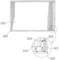
도 3은 본 발명을 프레임 스크린 구조로 사용 시 설명도3 is an explanatory diagram when using the present invention as a frame screen structure
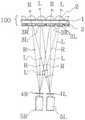
도 4는 본 발명 중 스크린의 작용 설명도4 is an explanatory view of the operation of the screen in the present invention;
도 5는 본 발명 중 스크린의 단면 구성 설명도Figure 5 is a cross-sectional configuration explanatory diagram of the screen of the present invention
도 6은 본 발명 중 반사 스크린의 구성 설명도6 is an explanatory view of the configuration of a reflective screen of the present invention;
도면의 부호에 대한 명칭의 간단한 설명Brief Description of Names to References in the Drawings
100. 스크린 200. 롤 업 장치 300. 프레임100.
1. 투과스크린 1a 반사스크린.1. Transmissive Screen 1a Reflective Screen.
2. 곡면라인 3. 영상 분할 면2.
3R. 좌 편광라인 3L. 우 편광라인3R.
4R. 좌 편광판 4L. 우 편광판4R.
5R. 좌상프로젝터 5L. 우상 프로젝터5R. Top
6. 반사면 201. 스크린 케이스6.
202. 회전 봉 203. 하단 봉202. Rotating Rod 203. Bottom Rod
301. 스크린 고정 봉 302. 스크린 조임선301. Screen retaining rod
303. 스크린 홀더303. Screen Holder
R. 좌 영상 L. 우 영상R. Left image L. Right image
본 발명은 일반 프로젝터영사용 스크린을 입체 영상용 스크린으로 발명 한 것이다The present invention invented a general projector projection screen as a screen for stereoscopic images
특히 편광 안경과 같은 보조 장치 없이 직접 입체 영상을 시청 할 수 있는 입체 영상용 스크린에 관한 것이다.In particular, the present invention relates to a stereoscopic screen for viewing stereoscopic images without an auxiliary device such as polarized glasses.
편광안경 없이 사용 하는 입체 영상으로 PDP나 LCD와 같은 영상 디스플레이를 이용하는 장치들이 있으나 이러한 장치들은 화면을 대형화하기 위해서는 디스플레이 그 자체가 커져야 하므로 영상 대형화에 한계가 있고 영상의 크기에 비례한 무게와 설치 부피가 커지고, 제조경비가 과다 하여 실용화에 한계가 있으며. 특히 입체영상 시청 시 시 좌, 우 시야각이 매우 협소한 단점이 있다.There are devices that use video display such as PDP and LCD as polarized glasses without polarizing glasses. However, these devices have a large display in order to enlarge the screen, so there is a limit to image enlargement and weight and installation volume proportional to the size of the image. Has become too large, and the manufacturing cost is excessive, there is a limit to the practical use. In particular, when viewing stereoscopic images, the left and right viewing angles are very narrow.
프로젝터는 투사거리에 따라 스크린의 화면을 손쉽게 대형으로 확대 할 수 있다.The projector can easily enlarge the screen on the screen according to the projection distance.
종래 입체 영상에 있어서 두 개의 프로젝터의 투사렌즈 앞에 각각의 편광 필터를 결합하고 종래 일반 스크린에 투사하는 방법이 보편적으로 알려져 있다.In conventional stereoscopic images, a method of combining respective polarizing filters in front of the projection lenses of two projectors and projecting them on a conventional general screen is generally known.
그러나 이러한 스크린에 투사하는 입체영상은 별도의 편광 안경을 사용해야 하므로 스크린에서의 영상의 밝기와 해상도가 급격히 저하되고, 눈의 피로를 가중 시키며, 특히 편광 안경을 착용한 사람만이 입체영상을 시청할 수 있으므로 특정된 사람만 시청이 가능하므로 광고 영상 장치 등에 사용이 불가 하였다.However, since stereoscopic images projected on such screens require the use of separate polarized glasses, the brightness and resolution of the image on the screen are sharply degraded, adding to eye fatigue, and only a person wearing polarized glasses can watch stereoscopic images. Therefore, only a specific person can watch, so it is not possible to use such as advertising video device.
상기 문제점을 해결하기 위하여 스크린에서 본 발명의 목적을 달성하려면To achieve the object of the present invention on the screen to solve the above problems
스크린으로 투사되는 영상을 초점 위치에서 영상을 결상 하는 기능, 즉 산란 기능이 있어야 하고.The image projected on the screen should have the function of image forming at the focus position, that is, scattering function.
동시에 영상이 투과하면서 좌. 우 영상을 분리하는 기능이 있어야 하며,At the same time the image is transmitted and left. It should have a function to separate the right image,
입체영상을 시청하기 위해서는 좌측 영상과 우측 영상을 미세하게 분리 하고 스크린 전체로는 좌, 우측 영상을 하나로 합치하는 기능이 있어야 한다.In order to watch a stereoscopic image, the left and right images must be finely divided and the left and right images must be combined into one.
또한 편광 안경 등 별도의 도구 없이 스크린에서 입체 영상을 감상하기 위해서는 좌, 우상이 분리하여 확대 된 후 각각 좌, 우측 눈에 시청되는 기능이 강구 되어야 한다.In addition, in order to enjoy stereoscopic images on the screen without a separate tool such as polarized glasses, the left and right images must be separated and enlarged, and then the left and right eyes must be viewed.
이러한 상기의 목적을 달성하기 위하여 본 발명은The present invention to achieve the above object
스크린에서 편광안경과 같은 보조 장치 없이 선명한 입체영상을 시청할 목적으로 투과기능과 산란기능을 겸용하는 스크린을 구성하고,In order to view clear stereoscopic images without auxiliary devices such as polarized glasses on the screen, the screen combines the transmission function and the scattering function,
동 스크린 전, 후면 중 일방에 프로젝터의 좌, 우 영상을 분리하여 투과하는 편광라인을 상, 하 방향으로 구성하고, 나머지 일방에 상기 편광라인과 같은 방향과 크기로 편광라인 따라 곡면 라인을 구성함으로서,Before and after the same screen, the left and right images of the projector are separated and transmitted through the polarization line in the up and down direction, and the other one is configured by the curved line along the polarization line in the same direction and size as the polarization line. ,
하나의 스크린에서 산란기능과 투과기능 및 좌, 우 영상을 세밀 하게 분리 투과 하게 하고 스크린 전체적으로는 합치하여 시야각이 넓고, 영상선명도가 높은 입체 영상용 스크린의 구성을 제시하고자 한다,The scattering function, the transmission function, and the left and right images are finely separated and transmitted in one screen, and the overall screen is consistent so that the composition of the screen for stereoscopic images with wide viewing angle and high image sharpness is proposed.
이러한 상기 제 조건을 충족하기 위한 입체스크린(100)의 구성이 매우 중요한 바 이를 도 4 및 도 5에 의해 상세히 설명하기로 한다.The configuration of the
도1및 도4와 도 5와 같이 입체스크린(100)의 기본이 되는 기재는 박막의 투명 소재로 하여 .그 소재 내부에 확산 재를 분포하거나 표면을 엠보싱 하여 입사되는 광원을 적당히 산란시키고 적당히 투과시키는 이른바 투과 스크린(1)으로 구성한다.1, 4, and 5, the base material of the three-
이러한 투과스크린(1)의 투과율은 약 10%-90% 사이에서 목적에 따라 조정한다.The transmittance of this
나머지 90%-10%는 산란율이 된다. 산란율과 스크린의 좌, 우 시야각은 반비례 하므로 적정한 투과율은 20%-40%이다.The remaining 90% -10% is the spawning rate. Since the scattering rate and the left and right viewing angles of the screen are inversely proportional, the proper transmittance is 20% -40%.
이러한 투과 스크린(1)의 전면, 즉 프로젝터의 영상이 입사 하는 방향의 표면으로 상, 하 방향으로 좌, 우 편광라인(3R, 3L)을 구성한다.The left and
이와 같은 좌, 우 편광라인(3R, 3L)은 편광필름을 소재로 하여 라인형태로 구성하되 한쪽의 편향 각은 45˚ 나머지 한 쪽은 -45˚각도로 하거나 또는 한쪽은 수평각도로, 한쪽은 수직각도로 하여. 각각의 편향 각을 상호 대칭각으로 구성한다.These left and right polarization lines (3R, 3L) is composed of a polarized film in the form of a line, but one of the deflection angle 45 ° the other side is -45 ° angle or one side is a horizontal angle, one side is vertical At an angle. Each deflection angle is composed of mutual symmetry angles.
이와 같이 구성 된 좌, 우 편광라인(3R, 3L)은 투과스크린(1)의 표면에 순차적으로 좌 편광라인(3R), 우 편광라인(3L)순으로 순차적으로 구성 하여 투과 스크 린(1) 의 좌. 우 방향으로 배열한다.The left and
상기 좌, 우 편광라인(3R, 3L) 크기 a1는 스크린 전체 크기에 따라 다르나 0.2MM에서 대형 스크린 일 경우에는 대형 전광판의 LED 크기와 같은 15MM 까지도 가능하다,The left and right polarization lines (3R, 3L) size a1 varies depending on the overall screen size, but in the case of a large screen from 0.2MM to 15MM, which is the same as the LED size of a large display board,
투과스크린(1) 후면에 상하 방향으로 투명한 소재의 곡면라인(2)을 구성하되 도1과 같이 동 곡면라인(2)의 크기 a 는 투과스크린(1) 전면의 좌, 우 편광라인(3R, 3L)의 크기인 a1과 동일하게 구성한다.A
즉 투과스크린(1)을 기본 기재로 하여 전. 후면으로 상호대칭 구조로 전면에는 좌, 우 편광라인(3R.3L)을 ,후면에는 투명한 소재의 곡면라인(2)을 형성하는 것이다.In other words, the transmission screen (1) as a base substrate before. It is a symmetrical structure to the rear to form left and right polarization lines (3R.3L) on the front, and the curved line (2) of transparent material on the back.
상기와 같은 곡면라인(2)의 형상은 좌우방향으로는 곡률에 의한 곡면으로 하고 상하 방향으로는 라인 형태로 구성하되 곡률은 좌, 우 편광라인(3R, 3L)의 폭과 같은 크기로 할 때 확대 효율은 최대치가 되나 최소 1/5까지도 가능 하다When the shape of the curved line (2) as described above is a curved surface by curvature in the left and right direction and in the form of a line in the vertical direction, the curvature is the same size as the width of the left and right polarization lines (3R, 3L) Magnification efficiency is maximum but can be as small as 1/5
예를 들면 곡면라인(2)의 폭 a가 1mm이면 곡면의 곡률직경은 1-5m/m 로 한다.For example, if the width a of the
즉 곡면라인(2)이 갖는 곡률의 확대 배율이 높을수록 좌, 우상의 분리도가 좋아지므로 입체감도가 높아진다.That is, the higher the magnification of the curvature of the
투과스크린(1)의 좌, 우 편광라인(3R, 3L)과 좌, 우 프로젝터(5R, 5L)에 구성 하는 좌, 우 편광판(4R,4L)의 편향각도는 동일한 각도로 구성한다.The deflection angles of the left and right
따라서 도 4와 같이 좌 프로젝터(5R)에서 좌 편광판(4R)에 의해 편광 되여 투사된 좌상(R)은 투과스크린(1) 전면에 순차적으로 배열한 좌, 우 편광라인(3R.3L)중 우 편광라인(3L)에서는 차단되고 좌 편광라인(3R)으로 만 투과된 후, 투과스크린(1)에서 영상을 결상 한 다,Accordingly, as shown in FIG. 4, the upper left R, which is polarized by the
같은 논리로 우 프로젝터(5L)에서 우 편광판(4L)에 의해 편광 된 우상(L)은 투과스크린(1)표면에 순차적으로 배열한 좌, 우 편광라인(3R.3L)중 좌 편광라인(3R)에서는 차단되고, 우 편광라인(3L)으로만 투과 된 후, 투과스크린(1)에서 영상으로 결상 된 다,Similarly, the right image L polarized by the
상기와 같이 투과스크린(1)에 결상된 좌, 우상(R. L)은 투과스크린(1) 의 후면의 각각의 곡면라인(2)에 의해 직진 확대되므로. 시청자는 상기 좌, 우상(R. L)을 미세한 곡면라인(2)에 의해 화소단위로 확대하면서 좌, 우상(R. L)을 순차적으로 합치하여 시청하게 되므로 편광안경 없이 입체영상을 시청하게 된다.Left and right (R. L) formed on the transmissive screen (1) as described above is enlarged straight by each curved line (2) of the rear of the transmissive screen (1). Viewers are viewing the stereoscopic image without polarized glasses because the left and right images (R. L) are enlarged by the fine curved line (2) in pixel units, and the left and right images (R. L) are sequentially matched. .
이때 투과스크린(1)은 도 5의 ∠A와 같이 입사된 프로젝터의 빛을 결상하여 좌, 우로 산란하는 작용을 하므로 매우 넓은 입체영상의 시야각∠A가 발생된다.In this case, the
약 20%의 투과율을 갖는 투과스크린(1)으로 구성할 경우 산란율은 80%에 이르므로 시야각∠A는 좌, 우 180˚의 80%는 약 144˚가 되므로 종래 평판디스플레이의 표준 시야각 40˚의 3배 이상의 시야각을 갖는다.In the case of the
또한 입체스크린(100) 내부 투과스크린(1)에서 결상한 영상을 표면의 곡면라인(2)으로 확대하고 외광은 곡면라인(2) 표면에서 외부로 확산하므로 종래 입체영상 대비 2배 이상의 밝기와 선명도를 시현 할 수 있는 장점이 있다.In addition, since the image formed in the transmissive screen (1) inside the stereoscopic screen (100) is expanded to the curved line (2) of the surface, and the external light diffuses from the surface of the curved line (2) to the outside, the brightness and clarity more than twice that of the conventional stereoscopic image There is an advantage that can be demonstrated.
[실시의 예1]Example 1
상기 입체스크린(100)의 구성 요소 중 좌, 우측 편광라인(3R, 3L)은 필름 소재로 구성하고, 표면의 곡면라인(2)은 투명한 실리콘 고무 또는 우레탄 소재와 같이 연질로 구성하여 입체스크린(100) 전체가 롤(roll)처럼 말 수 있는 소재로 한 다음Left and right polarization lines (3R, 3L) of the components of the three-
도 1 및 도2와 같이 입체스크린(100)을 수납 할 수 있는 스크린 케이스(201)와 입체스크린(100)을 모터 등으로 감아 회전 시키는 회전 봉(202)과 입체스크린(100) 하단을 지지하는 하단 봉(203)과 결합하여 롤-업 형태의 입체스크린으로 구성 한다.As shown in FIGS. 1 and 2, the
[실시의 예 2]Example 2
도 6은 상기에서 설명한 입체스크린(100) 구조 뒷면에 반사면(6)을 추가 구성 한 것 이다,6 is an additional configuration of the reflective surface 6 on the back of the three-
즉 투과스크린(1)을 전, 후하여 전면으로는 곡면라인(2)을, 후면으로 좌, 우 편광라인(3R, 3L)을 구성 하고 그 이면에 반사면(6)을 추가하여 반사형 스크린으로 구성 한 것 이다That is, before and after the
이와 같은 실시의 예는 도 6과 같이 곡면라인(2)으로 입사한 영상을 투과스크린(1)에서 결상하고 좌. 우 편광판(3R.3L)을 통과 한 후 반사면(6)에서 반사하게 되는 것 이다In this embodiment, as shown in FIG. 6, the image incident on the
[실시의 예 3]Example 3
입체 스크린(100)의 형상을 도 3과 같이 프레임(300)구조와 결합 구성하는 예이다.As shown in FIG. 3, the shape of the
일반적으로 스크린의 평탄성이 나쁘면 입체 영상의 균일도가 저해 된다,In general, poor screen flatness impairs uniformity of stereoscopic images.
따라서 상기 입체 스크린(100)의 주위를 일정한 간격으로 펀칭한 다음 이를 프레임(300)내부의 고정 대(301)에 스프링이나 고무줄과 같은 탄력소재 등으로 구성된 스크린 조임선(302)과 연결하여 투과스크린(1)자체를 탄력있게 사방에서 당기는 구조이다.Therefore, the punching around the three-
이와 같은 구조는 투과스크린(1) 자체의 평탄성이 매우 양호하므로 대각선 2M 이상의 초대형 스크린 에 적합하다,Such a structure is suitable for a very large screen with a diagonal of 2M or more since the flatness of the
상기와 입체스크린(100)의 각 구성 요소 중 투과스크린(1), 반사 면(6), 좌, 우 편광라인(3R.3L)의 구성순서는 필요에 따라 달리 해도 효과는 같다.Among the components of the three-
또한 상기 논리 이내에서 입체스크린(100)의 표면에 좌, 우측 편광 라인(3R,3L) 대신에 패러랙스 배리어 방식의 편광구조로 대체하여 구성 할 수 있다In addition, instead of the left and
이러한 발명은 두 개의 일반 프로젝터에 간단히 편광필터만 결합하여 본 발명에 투사 할 시This invention is simply combined with a polarization filter to two ordinary projectors when projecting to the present invention
별도의 편광안경 없이 입체스크린(100)에서 직접 입체 영상 시청이 가능하고, 입체영상을 시청 할 수 있는 시야각이 종래 대비 3배 이상 넓으며, 선명도 또한 2배 이상 증배 할 수 있으며,It is possible to watch stereoscopic images directly on the
입체스크린(100)의 소재를 필요에 따라 필름과 같은 연질 등의 소재로 구성하여 필요에 따라 롤-업 스크린으로 구성 할 수 있으며,If necessary, the material of the three-
입체스크린(100)을 별도 프레임(300)과 결합한 구조로 구성 할시 평탄성이 양호한 입체 대형스크린구성이 가능 한 것이다.When the three-
따라서 이러한 본 발명은 입체스크린(100)에서 초대형 입체 영상을 선명하게 시청 할 수 있으므로 입체 영상 광고 장치, 입체영상장치 등으로 매우 효율적인 발명이다.Therefore, the present invention is a very efficient invention as a three-dimensional image advertising device, three-dimensional image device, etc., because the
Claims (5)
Translated fromKoreanPriority Applications (5)
| Application Number | Priority Date | Filing Date | Title |
|---|---|---|---|
| KR1020060113089AKR20080044370A (en) | 2006-11-16 | 2006-11-16 | Stereoscopic screen |
| US11/798,660US20080117506A1 (en) | 2006-11-16 | 2007-05-16 | Three-dimensional image forming screen |
| GB0720867AGB2443916B (en) | 2006-11-16 | 2007-10-24 | Three-dimensional image formimg screen |
| JP2007280011AJP2008129592A (en) | 2006-11-16 | 2007-10-29 | Screen for forming three-dimensional image |
| CNA2007101871071ACN101183209A (en) | 2006-11-16 | 2007-11-14 | Three dimensional image forming screen |
Applications Claiming Priority (1)
| Application Number | Priority Date | Filing Date | Title |
|---|---|---|---|
| KR1020060113089AKR20080044370A (en) | 2006-11-16 | 2006-11-16 | Stereoscopic screen |
Publications (1)
| Publication Number | Publication Date |
|---|---|
| KR20080044370Atrue KR20080044370A (en) | 2008-05-21 |
Family
ID=38829865
Family Applications (1)
| Application Number | Title | Priority Date | Filing Date |
|---|---|---|---|
| KR1020060113089ACeasedKR20080044370A (en) | 2006-11-16 | 2006-11-16 | Stereoscopic screen |
Country Status (5)
| Country | Link |
|---|---|
| US (1) | US20080117506A1 (en) |
| JP (1) | JP2008129592A (en) |
| KR (1) | KR20080044370A (en) |
| CN (1) | CN101183209A (en) |
| GB (1) | GB2443916B (en) |
Cited By (2)
| Publication number | Priority date | Publication date | Assignee | Title |
|---|---|---|---|---|
| KR20100034692A (en)* | 2008-09-23 | 2010-04-01 | 최해용 | Transmission screen for stereoscopic images |
| KR20200002642U (en)* | 2019-05-27 | 2020-12-07 | 신우훈 | Roll Screen Device of Elevating and Spreading Type |
Families Citing this family (9)
| Publication number | Priority date | Publication date | Assignee | Title |
|---|---|---|---|---|
| KR20120037454A (en)* | 2009-07-08 | 2012-04-19 | 톰슨 라이센싱 | Method and system for color correction for three-dimensional(3d) projection |
| ES2741815T3 (en) | 2009-10-30 | 2020-02-12 | Koninklijke Philips Nv | Display device |
| KR101205130B1 (en)* | 2010-07-12 | 2012-11-26 | 최해용 | the reflective projection screen with multi incident angle |
| FR2990031B1 (en)* | 2012-04-27 | 2014-05-09 | Robert Miggiano | SCREEN PROJECTION SCREEN DEVICE |
| US8570651B1 (en)* | 2012-06-04 | 2013-10-29 | Hae-Yong Choi | Both side screen for combined use of 2D/3D images |
| CN102707554A (en)* | 2012-06-05 | 2012-10-03 | 宁波Gqy视讯股份有限公司 | Bare three-dimensional splicing display unit and splicing display device thereof |
| WO2015180646A1 (en)* | 2014-05-27 | 2015-12-03 | Mediatek Inc. | Projection display component and electronic device |
| WO2019140162A2 (en)* | 2018-01-11 | 2019-07-18 | Arovia, Inc. | Spontaneous pop-up display device with attached screen |
| IT201900006008A1 (en)* | 2019-04-17 | 2020-10-17 | Raul Maria Orlandi | INTEGRATED SYSTEM FOR THE PRODUCTION OF INTERFERENTIAL SCREENS, INTERFACED WITH VIDEO MODULES OF THE LED WALL TYPE AND SIMILAR FOR THE GENERATION OF STATIC, KINETIC AND ANIMATED THREE-DIMENSIONAL IMAGES, USEABLE WITHOUT THE AID OF CLASSIC STEREOSCOPIC DEVICES. |
Family Cites Families (12)
| Publication number | Priority date | Publication date | Assignee | Title |
|---|---|---|---|---|
| US3510197A (en)* | 1966-12-09 | 1970-05-05 | Hitachi Ltd | Projection screen |
| JPS62266980A (en)* | 1986-05-15 | 1987-11-19 | Kawasaki Heavy Ind Ltd | Picture projecting system |
| JPH0418893A (en)* | 1990-05-14 | 1992-01-23 | Nippon Telegr & Teleph Corp <Ntt> | Stereoscopic display device |
| JPH05273656A (en)* | 1992-03-26 | 1993-10-22 | Toppan Printing Co Ltd | Screen for stereoscopic observation and method of manufacturing |
| US5337179A (en)* | 1992-07-27 | 1994-08-09 | Hodges Marvin P | Flexible controllable optical surface and method of making the same |
| JP2926454B2 (en)* | 1992-10-02 | 1999-07-28 | 大日本印刷株式会社 | Reflective projection screen |
| GB2296151A (en)* | 1994-12-16 | 1996-06-19 | Sharp Kk | Autosteroscopic display device |
| JPH08186849A (en)* | 1995-01-06 | 1996-07-16 | Sony Corp | Stereoscopic visual device |
| US6710920B1 (en)* | 1998-03-27 | 2004-03-23 | Sanyo Electric Co., Ltd | Stereoscopic display |
| KR100753340B1 (en)* | 2002-10-21 | 2007-08-30 | 최해용 | Both-side Image Film Screen |
| TW200718173A (en)* | 2005-07-14 | 2007-05-01 | Koninkl Philips Electronics Nv | Autostereoscopic display apparatus |
| KR101128519B1 (en)* | 2005-08-04 | 2012-03-27 | 삼성전자주식회사 | High resolution autostereoscopic display |
- 2006
- 2006-11-16KRKR1020060113089Apatent/KR20080044370A/ennot_activeCeased
- 2007
- 2007-05-16USUS11/798,660patent/US20080117506A1/ennot_activeAbandoned
- 2007-10-24GBGB0720867Apatent/GB2443916B/ennot_activeExpired - Fee Related
- 2007-10-29JPJP2007280011Apatent/JP2008129592A/enactivePending
- 2007-11-14CNCNA2007101871071Apatent/CN101183209A/enactivePending
Cited By (2)
| Publication number | Priority date | Publication date | Assignee | Title |
|---|---|---|---|---|
| KR20100034692A (en)* | 2008-09-23 | 2010-04-01 | 최해용 | Transmission screen for stereoscopic images |
| KR20200002642U (en)* | 2019-05-27 | 2020-12-07 | 신우훈 | Roll Screen Device of Elevating and Spreading Type |
Also Published As
| Publication number | Publication date |
|---|---|
| US20080117506A1 (en) | 2008-05-22 |
| GB2443916A (en) | 2008-05-21 |
| GB2443916B (en) | 2009-04-01 |
| CN101183209A (en) | 2008-05-21 |
| JP2008129592A (en) | 2008-06-05 |
| GB0720867D0 (en) | 2007-12-05 |
Similar Documents
| Publication | Publication Date | Title |
|---|---|---|
| KR20080044370A (en) | Stereoscopic screen | |
| US7562983B2 (en) | Three-dimensional display device | |
| JP4027898B2 (en) | Polarized transmission screen and stereoscopic image display apparatus using the polarized transmission screen | |
| JP4644594B2 (en) | 3D image display device | |
| US7995166B2 (en) | Display panel, display device, and terminal device | |
| US8836755B2 (en) | Two dimensional media combiner for creating three dimensional displays | |
| JP2005215325A (en) | Stereoscopic image display device | |
| US7230759B2 (en) | Autostereoscopic projection screen | |
| US7699472B2 (en) | Multi-view autostereoscopic projection system using single projection lens unit | |
| KR20060130887A (en) | Screen and Projection System for Projected 3D Images | |
| JP5224236B2 (en) | Display panel, display device, and terminal device | |
| WO2012111496A1 (en) | Display device and display method | |
| US9554124B1 (en) | Image display with full-depth viewing | |
| RU2275754C2 (en) | Device for watching stereoscopic image represented by video display aid (versions) | |
| CN1567026A (en) | Single unit stereoscopic image projection arrangement | |
| CN104570367B (en) | A kind of 3 d display device | |
| KR20040026032A (en) | 3-dimension display system | |
| CN103402111B (en) | Big-sized 2D-3D switching display device | |
| JPH08149520A (en) | Stereoscopic video image display device | |
| KR100293692B1 (en) | Stereoscopic Display | |
| JP3818289B2 (en) | Transmission screen and rear projection display device | |
| KR100499920B1 (en) | Both sides regular picture projection system | |
| KR20020039479A (en) | 3-D image system | |
| JP2011090191A (en) | Stereoscopic image display device | |
| JP2999953B2 (en) | Stereoscopic image display using polarized glasses |
Legal Events
| Date | Code | Title | Description |
|---|---|---|---|
| PA0109 | Patent application | Patent event code:PA01091R01D Comment text:Patent Application Patent event date:20061116 | |
| PG1501 | Laying open of application | ||
| A201 | Request for examination | ||
| PA0201 | Request for examination | Patent event code:PA02012R01D Patent event date:20110922 Comment text:Request for Examination of Application Patent event code:PA02011R01I Patent event date:20061116 Comment text:Patent Application | |
| E902 | Notification of reason for refusal | ||
| PE0902 | Notice of grounds for rejection | Comment text:Notification of reason for refusal Patent event date:20121016 Patent event code:PE09021S01D | |
| E601 | Decision to refuse application | ||
| PE0601 | Decision on rejection of patent | Patent event date:20130124 Comment text:Decision to Refuse Application Patent event code:PE06012S01D Patent event date:20121016 Comment text:Notification of reason for refusal Patent event code:PE06011S01I |